EP4400777A1 - Ceiling-embedded air conditioner - Google Patents
Ceiling-embedded air conditioner Download PDFInfo
- Publication number
- EP4400777A1 EP4400777A1 EP22872605.5A EP22872605A EP4400777A1 EP 4400777 A1 EP4400777 A1 EP 4400777A1 EP 22872605 A EP22872605 A EP 22872605A EP 4400777 A1 EP4400777 A1 EP 4400777A1
- Authority
- EP
- European Patent Office
- Prior art keywords
- shroud
- axis
- ceiling
- turbo fan
- air conditioner
- Prior art date
- Legal status (The legal status is an assumption and is not a legal conclusion. Google has not performed a legal analysis and makes no representation as to the accuracy of the status listed.)
- Pending
Links
- 230000002093 peripheral effect Effects 0.000 claims abstract description 15
- 238000000926 separation method Methods 0.000 claims description 9
- 230000000694 effects Effects 0.000 description 4
- 230000015572 biosynthetic process Effects 0.000 description 3
- 239000003507 refrigerant Substances 0.000 description 3
- 230000004048 modification Effects 0.000 description 2
- 238000012986 modification Methods 0.000 description 2
- 238000004378 air conditioning Methods 0.000 description 1
- 238000004519 manufacturing process Methods 0.000 description 1
Images



Classifications
-
- F—MECHANICAL ENGINEERING; LIGHTING; HEATING; WEAPONS; BLASTING
- F24—HEATING; RANGES; VENTILATING
- F24F—AIR-CONDITIONING; AIR-HUMIDIFICATION; VENTILATION; USE OF AIR CURRENTS FOR SCREENING
- F24F1/00—Room units for air-conditioning, e.g. separate or self-contained units or units receiving primary air from a central station
- F24F1/0007—Indoor units, e.g. fan coil units
- F24F1/0018—Indoor units, e.g. fan coil units characterised by fans
- F24F1/0022—Centrifugal or radial fans
-
- F—MECHANICAL ENGINEERING; LIGHTING; HEATING; WEAPONS; BLASTING
- F04—POSITIVE - DISPLACEMENT MACHINES FOR LIQUIDS; PUMPS FOR LIQUIDS OR ELASTIC FLUIDS
- F04D—NON-POSITIVE-DISPLACEMENT PUMPS
- F04D29/00—Details, component parts, or accessories
- F04D29/26—Rotors specially for elastic fluids
- F04D29/28—Rotors specially for elastic fluids for centrifugal or helico-centrifugal pumps for radial-flow or helico-centrifugal pumps
- F04D29/30—Vanes
-
- F—MECHANICAL ENGINEERING; LIGHTING; HEATING; WEAPONS; BLASTING
- F24—HEATING; RANGES; VENTILATING
- F24F—AIR-CONDITIONING; AIR-HUMIDIFICATION; VENTILATION; USE OF AIR CURRENTS FOR SCREENING
- F24F1/00—Room units for air-conditioning, e.g. separate or self-contained units or units receiving primary air from a central station
- F24F1/0007—Indoor units, e.g. fan coil units
- F24F1/0043—Indoor units, e.g. fan coil units characterised by mounting arrangements
- F24F1/0047—Indoor units, e.g. fan coil units characterised by mounting arrangements mounted in the ceiling or at the ceiling
Definitions
- the present disclosure relates to a ceiling-embedded air conditioner.
- the ceiling-embedded air conditioner mainly includes a casing embedded in a ceiling indoors, a motor having an output shaft that rotates around an axis extending in an up-down direction, a turbo fan, a main plate that fixes the turbo fan to the output shaft, a heat exchanger that surrounds the turbo fan, and a bell mouth.
- the turbo fan has a tubular shroud that surrounds the axis, and a plurality of main blades that are arranged to be spaced apart from each other in a circumferential direction on a surface of the shroud on one side.
- Indoor air is taken into the casing from a central portion of the casing by rotating the turbo fan.
- the air is pumped to an outer peripheral side by the turbo fan and then passes through the heat exchanger to become cold air or warm air to be supplied indoors.
- a flow path cross-sectional area of a turbo fan outlet is determined by a head or flow rate required for a product.
- a projected area (a product of a height in a direction of the axis and a length in the circumferential direction) of the heat exchanger as viewed in a radial direction is determined by a temperature adjustment ability required for a product.
- the projected area of the heat exchanger is set to be larger than the flow path cross-sectional area of the turbo fan outlet. That is, to increase the height of the heat exchanger in the direction of the axis, the flow path cross-sectional area rapidly increases from the turbo fan toward the heat exchanger.
- a part of a flow of the air flowing out of the turbo fan may form a circulation flow in front of the heat exchanger, and a flow speed distribution may be non-uniform.
- a performance of the heat exchanger cannot be sufficiently utilized in a region where a flow speed is low, and an efficiency of the ceiling-embedded air conditioner is deteriorated.
- the present disclosure has been made to solve the above-described problems, and an object of the present disclosure is to provide a ceiling-embedded air conditioner with a further improvement in the efficiency.
- a ceiling-embedded air conditioner includes a motor having an output shaft that is rotatable about an axis, a turbo fan attached to the output shaft, and a heat exchanger that surrounds the turbo fan from an outer peripheral side and has a dimension in a direction of the axis larger than a dimension of an outlet flow path of the turbo fan in the direction of the axis, in which the turbo fan includes a main plate that is attached to the output shaft and has a disk shape centered on the axis, a shroud that is disposed to be spaced apart from the main plate in the direction of the axis, a plurality of main blades that are provided across the shroud and the main plate and are arranged to be spaced apart from each other in a circumferential direction, and a guide member that protrudes in the circumferential direction from a pressure surface, which is a surface of the main blade facing a forward side of the output shaft in a rotational direction, and has
- the ceiling-embedded air conditioner 100 includes a casing 1, a motor 2, a main plate 3, a turbo fan 4, a heat exchanger 5, and a bell mouth 6.
- the casing 1 is embedded in a ceiling wall 90 of a building.
- the casing 1 has a rectangular shape as viewed from below, and is recessed upward to form a space therein.
- the casing 1 includes a panel 1a exposed to a ceiling surface 90a and a box-shaped cabinet 1b provided above the panel 1a.
- the panel 1a includes a panel body 11 that is a rectangular frame body, and a grill 12 as a suction port 11a provided at a lower center.
- the panel body 11 forms a blowout port 11b around the suction port 11a.
- the motor 2 is provided at a central portion of a bottom surface 1s facing downward in the cabinet 1b.
- the motor 2 has a motor body 21 that accommodates a coil, a magnet, and the like, and an output shaft 22 that protrudes vertically downward from the motor body 21.
- the output shaft 22 is rotationally driven about an axis O extending in the vertical direction (up-down direction).
- the disk-shaped main plate 3 that extends radially outward from the output shaft 22 and that is centered on the axis O is fixed to the output shaft 22.
- the main plate 3 has a cross-sectional shape that extends from below to above from an inner side to the outer side in the radial direction in a cross-sectional view including the axis O.
- the turbo fan 4 is attached to a portion of a lower surface of the main plate 3 that includes an outer side end edge in the radial direction.
- the turbo fan 4 has a plurality of main blades 41 arranged to be spaced apart from each other in the circumferential direction, an annular shroud 42 that covers the main blades 41 from below, and a guide member 43 provided on a surface of the main blades 41. A detailed configuration of the turbo fan 4 will be described later.
- the main plate 3 and the turbo fan 4 rotate with the rotation of the output shaft 22, and air sucked from the suction port 11a is sent radially outward.
- the circular heat exchanger 5 that surrounds the turbo fan 4 is provided radially outside the turbo fan 4.
- the heat exchanger 5 is a portion of a refrigerant circuit having a refrigerating cycle.
- a dimension in a direction of the axis O is set to be larger than a dimension of an outlet flow path of the turbo fan 4 in the direction of the axis O.
- a lower end surface of the heat exchanger 5 protrudes downward than the turbo fan 4.
- a cross-sectional area of the heat exchanger 5 as viewed in the radial direction (a product of a height of the heat exchanger 5 in the direction of the axis O and a length of the heat exchanger 5 in the circumferential direction) is larger than a cross-sectional area of an outlet of the turbo fan 4. Therefore, a flow path cross-sectional area rapidly increases from the outlet of the turbo fan 4 toward the heat exchanger 5.
- the air sent to the heat exchanger 5 by the turbo fan 4 is heat-exchanged with a refrigerant in a case of passing through the heat exchanger 5. Accordingly, the air that has flowed out to an outer peripheral side of the heat exchanger 5 becomes cold air or warm air.
- the air flows downward along a side surface of the cabinet 1b and is supplied into a room from the blowout port 11b.
- the bell mouth 6 fixed to an upper portion of the panel body 11 is disposed below the turbo fan 4.
- the bell mouth 6 is provided to guide the air introduced from the suction port 11a and send the air to the turbo fan 4.
- the bell mouth 6 has a conical shape that gradually contracts from below to above.
- An end portion of the bell mouth 6 on one side (upper side) in the direction of the axis O is surrounded by the above-described shroud 42 from an outer peripheral side.
- the shroud 42 is curved radially outward from the other side to one side in the direction of the axis O.
- the shroud 42 is curved radially outward from below to above in the direction of the axis O.
- a surface facing an inner peripheral side is a shroud inner peripheral surface 42s.
- the plurality of main blades 41 arranged to be spaced apart from each other in the circumferential direction with respect to the axis O are provided on the shroud inner peripheral surface 42s.
- the main blade 41 extends from the lower surface of the main plate 3 to the shroud inner peripheral surface 42s.
- a cross-sectional shape of the main blade 41 that is orthogonal to the axis O has a two-dimensional blade shape. More specifically, the cross-sectional shape of the main blade 41 has a rectangular shape as an example.
- a leading edge 41a (that is, an inner side end edge in the radial direction) of the main blade 41 extends in the direction of the axis O.
- a trailing edge 41b (that is, an outer side end edge in the radial direction) of the main blade 41 also extends in the direction of the axis O.
- a surface facing a forward side of the output shaft 22 in a rotational direction is a pressure surface 41p
- a surface facing a rear side in the rotational direction is a negative pressure surface 41n.
- the guide member 43 is provided between a pair of main blades 41 adjacent to each other in the circumferential direction.
- the guide member 43 divides a surface of the main blade 41 into a plurality of (two) regions.
- the guide member 43 is positioned at a central portion of the main blade 41 in the direction of the axis O.
- the guide member 43 extends from the pressure surface 41p of one main blade 41 to the negative pressure surface 41n of the other main blade 41. That is, the guide member 43 continuously extends in the circumferential direction.
- the guide member 43 may be provided on at least the pressure surface 41p and may not be connected to a negative pressure surface 41n side. That is, it is possible to adopt a configuration in which the guide member 43 protrudes from only the pressure surface 41p in the circumferential direction.
- An inner side end edge of the guide member 43 in the radial direction is positioned on the leading edge 41a of the main blade 41.
- an outer side end edge of the guide member 43 in the radial direction is positioned on the trailing edge 41b of the main blade 41.
- a shape of the guide member 43 is not limited to the above, and the inner side end edge of the guide member 43 in the radial direction may not be positioned on the leading edge 41a. In addition, the outer side end edge of the guide member 43 in the radial direction may not be positioned on the trailing edge 41b.
- the guide member 43 is curved along a direction in which the shroud 42 extends. That is, the guide member 43 is curved radially outward from the other side to one side in the direction of the axis O.
- the guide member 43 may not be completely curved along the direction in which the shroud 42 extends, and may extend in substantially the same direction as the shroud 42.
- a surface facing a shroud 42 side is a guide surface 43a.
- a separation distance between the guide surface 43a and the shroud inner peripheral surface 42s is constant from the inner side to the outer side in the radial direction. Note that being “constant” here referred to means being substantially constant, and for example, design tolerances and manufacturing errors are allowed. That is, the separation distance between the guide surface 43a and the shroud inner peripheral surface 42s may not be completely constant.
- the separation distance between the shroud 42 and the guide surface 43a can also be set as follows. That is, a configuration can be adopted in which the guide surface 43a extends to be close to the shroud 42 side as the guide surface 43a is directed radially outward in a range not falling below a reduction ratio of the flow path cross-sectional area from the inner side to the outer side in the radial direction in a flow path between the main plate 3 and the shroud 42.
- the motor 2 is first driven.
- the output shaft 22, the main plate 3, and the turbo fan 4 rotate around the axis O by driving the motor 2.
- the air is sent to the turbo fan 4 via the bell mouth 6 and then is pumped radially outward to form a main flow.
- the main flow flows along the lower surface of the main plate 3. That is, the main flow flows from the inner side to the outer side in the radial direction from below to above.
- Most of the main flow is heat-exchanged with the refrigerant by passing through the heat exchanger 5, and becomes cold air or warm air to be supplied into the room from the blowout port 11b.
- a flow path cross-sectional area of the outlet of the turbo fan 4 is determined by a head or flow rate required for a product.
- the cross-sectional area of the heat exchanger 5 as viewed in the radial direction is determined by a temperature adjustment ability required for a product.
- a cross-sectional area of the heat exchanger 5 is set to be larger than the flow path cross-sectional area of the outlet of the turbo fan 4 as in the present embodiment. That is, the flow path cross-sectional area rapidly increases from the turbo fan 4 toward the heat exchanger 5.
- a part of the flow of the air flowing out of the turbo fan 4 may form a circulation flow in front of a flow path between the heat exchanger 5 and the turbo fan 4, and a flow speed distribution may be non-uniform.
- a performance of the heat exchanger 5 cannot be sufficiently utilized, and an efficiency of the ceiling-embedded air conditioner 100 is deteriorated.
- the guide member 43 is provided in the main blade 41. According to this configuration, the flow of the air radially outward along the main blade 41 of the turbo fan 4 is divided into a plurality of flows in the direction of the axis O by the guide member 43. Thereby, the flow speed distribution in the direction of the axis O can be further made uniform at the outlet of the turbo fan 4. As a result, for example, the formation of the circulation flow in front of the heat exchanger 5 is suppressed. Therefore, the flow of the air is supplied to an entire cross-sectional area of the heat exchanger 5, and the performance as the heat exchanger 5 can be sufficiently utilized. Therefore, it is possible to improve the efficiency of the ceiling-embedded air conditioner 100.
- the guide member 43 continuously extends from the pressure surface 41p to the negative pressure surface 41n in the circumferential direction, the flow speed distribution can be stably made uniform over an entire region in the circumferential direction. As a result, it is possible to further suppress the formation of the above-described circulation flow.
- the guide member 43 extends from the leading edge 41a to the trailing edge 41b, the flow of the air can be more stably guided over an entire region in the radial direction.
- the separation distance between the guide member 43 (guide surface 43a) and the shroud 42 is constant from the inner side to the outer side in the radial direction, it is possible to minimize an occurrence of pressure loss because of a disposition of the guide member 43. In this way, the efficiency of the ceiling-embedded air conditioner 100 can be further improved.
- the example has been described in which only one guide member 43 is provided in the direction of the axis O.
- the number of the guide members 43 is not limited to the above, and as shown in Fig. 3 as a modification example, a plurality of (two or more) guide members 43 can be arranged to be spaced apart from each other in the direction of the axis O. With this configuration, the flow of the air radially outward is further finely divided, and thus it is possible to further make the flow speed distribution in the direction of the axis O uniform.
- a second embodiment of the present disclosure will be described with reference to Fig. 4 .
- the same configurations as those of the first embodiment will be assigned with the same reference numerals, and detailed description thereof will be omitted.
- a plurality of guide members 43 are arranged to be spaced apart from each other in the direction of the axis O. Further, the plurality of guide members 43 are disposed to be biased toward the shroud 42 side with respect to a main plate 3 side in the direction of the axis O. That is, the separation distance between the guide member 43 and the shroud 42 is set to be smaller than a separation distance between the guide member 43 and the main plate 3.
- a curvature of a shape on the shroud 42 side is larger than that on the main plate 3 side. Therefore, as is apparent from arrows in Fig. 1 , a direction of the flow changes rapidly from the direction of the axis O to the radial outer side on the shroud 42 side. Accordingly, a loss tends to increase on the shroud 42 side.
- the guide member 43 since the guide member 43 is disposed to be biased toward the shroud 42 side, a rectifying effect on the shroud 42 side can be further enhanced. As a result, it is possible to reduce the loss. As a result, it is possible to further improve the efficiency of the ceiling-embedded air conditioner 100.
- the second embodiment of the present disclosure has been described above. Various changes or improvements can be made to the configuration without departing from the concept of the present disclosure.
- the example has been described in which the plurality of guide members 43 are provided.
- a third embodiment of the present disclosure will be described with reference to Fig. 5 .
- the same configurations as in each of the embodiments described above are denoted by the same reference numerals, and detailed description thereof is omitted.
- a shape of the trailing edge 41b of the main blade 41 is different from that of each of the above-described embodiments.
- an end portion of the main blade 41 on the shroud 42 side is positioned radially outside an end portion of the main plate 3 side.
- the trailing edge 41b of the main blade 41 extends radially outward from the main plate 3 side toward the shroud 42 side. That is, the trailing edge 41b is inclined with respect to the axis O.
- the trailing edge 41b of the main blade 41 extends radially outward from the main plate 3 side toward the shroud 42 side. That is, the main blade 41 protrudes radially outward on the shroud 42 side. Accordingly, a work of the main blade 41 on the shroud 42 side with respect to the flow of the air is increased, and a head can be increased. As a result, it is possible to reduce the loss on the shroud 42 side. As a result, it is possible to further improve the efficiency of the ceiling-embedded air conditioner 100.
- the ceiling-embedded air conditioner 100 in each embodiment is grasped as follows, for example.
- the trailing edge 41b of the main blade 41 extends radially outward from the main plate 3 side toward the shroud 42 side. That is, the main blade 41 protrudes radially outward on the shroud 42 side. Accordingly, the work of the main blade 41 on the shroud 42 side is increased, and the head can be increased. As a result, it is possible to reduce the loss on the shroud 42 side.
Landscapes
- Engineering & Computer Science (AREA)
- Mechanical Engineering (AREA)
- General Engineering & Computer Science (AREA)
- Chemical & Material Sciences (AREA)
- Combustion & Propulsion (AREA)
- Structures Of Non-Positive Displacement Pumps (AREA)
- Air-Conditioning Room Units, And Self-Contained Units In General (AREA)
Abstract
Description
- The present disclosure relates to a ceiling-embedded air conditioner.
- This application claims priority to
Japanese Patent Application No. 2021-152971, filed in Japan on September 21, 2021 - As an example of an air conditioning device, a ceiling-embedded air conditioner as disclosed in
PTL 1 below is widely used. The ceiling-embedded air conditioner mainly includes a casing embedded in a ceiling indoors, a motor having an output shaft that rotates around an axis extending in an up-down direction, a turbo fan, a main plate that fixes the turbo fan to the output shaft, a heat exchanger that surrounds the turbo fan, and a bell mouth. The turbo fan has a tubular shroud that surrounds the axis, and a plurality of main blades that are arranged to be spaced apart from each other in a circumferential direction on a surface of the shroud on one side. - Indoor air is taken into the casing from a central portion of the casing by rotating the turbo fan. The air is pumped to an outer peripheral side by the turbo fan and then passes through the heat exchanger to become cold air or warm air to be supplied indoors.
- [PTL 1]
Japanese Patent No. 6130137 - Here, a flow path cross-sectional area of a turbo fan outlet is determined by a head or flow rate required for a product. Meanwhile, a projected area (a product of a height in a direction of the axis and a length in the circumferential direction) of the heat exchanger as viewed in a radial direction is determined by a temperature adjustment ability required for a product. In many cases, the projected area of the heat exchanger is set to be larger than the flow path cross-sectional area of the turbo fan outlet. That is, to increase the height of the heat exchanger in the direction of the axis, the flow path cross-sectional area rapidly increases from the turbo fan toward the heat exchanger. Therefore, a part of a flow of the air flowing out of the turbo fan may form a circulation flow in front of the heat exchanger, and a flow speed distribution may be non-uniform. As a result, there is a concern that a performance of the heat exchanger cannot be sufficiently utilized in a region where a flow speed is low, and an efficiency of the ceiling-embedded air conditioner is deteriorated.
- The present disclosure has been made to solve the above-described problems, and an object of the present disclosure is to provide a ceiling-embedded air conditioner with a further improvement in the efficiency.
- To solve the above-described problems, a ceiling-embedded air conditioner according to the present disclosure includes a motor having an output shaft that is rotatable about an axis, a turbo fan attached to the output shaft, and a heat exchanger that surrounds the turbo fan from an outer peripheral side and has a dimension in a direction of the axis larger than a dimension of an outlet flow path of the turbo fan in the direction of the axis, in which the turbo fan includes a main plate that is attached to the output shaft and has a disk shape centered on the axis, a shroud that is disposed to be spaced apart from the main plate in the direction of the axis, a plurality of main blades that are provided across the shroud and the main plate and are arranged to be spaced apart from each other in a circumferential direction, and a guide member that protrudes in the circumferential direction from a pressure surface, which is a surface of the main blade facing a forward side of the output shaft in a rotational direction, and has a guide surface that faces a shroud side.
- According to the present disclosure, even in a ceiling-embedded air conditioner in which the flow path cross-sectional area rapidly increases from the turbo fan to the heat exchanger, it is possible to provide a ceiling-embedded air conditioner with a further improvement in efficiency.
-
-
Fig. 1 is a sectional view showing a configuration of a ceiling-embedded air conditioner according to a first embodiment of the present disclosure. -
Fig. 2 is an enlarged view showing a configuration of a turbo fan according to the first embodiment of the present disclosure. -
Fig. 3 is an enlarged view showing a modification example of the turbo fan according to the first embodiment of the present disclosure. -
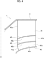
Fig. 4 is an enlarged view showing a configuration of a turbo fan according to a second embodiment of the present disclosure. -
Fig. 5 is an enlarged view showing a configuration of a turbo fan according to a third embodiment of the present disclosure. - Hereinafter, a ceiling-embedded
air conditioner 100 as a centrifugal compressor according to the first embodiment of the present disclosure will be described with reference toFigs. 1 to 4 . As shown inFig. 1 , the ceiling-embeddedair conditioner 100 includes acasing 1, amotor 2, amain plate 3, aturbo fan 4, aheat exchanger 5, and abell mouth 6. - The
casing 1 is embedded in aceiling wall 90 of a building. Thecasing 1 has a rectangular shape as viewed from below, and is recessed upward to form a space therein. Specifically, thecasing 1 includes apanel 1a exposed to aceiling surface 90a and a box-shaped cabinet 1b provided above thepanel 1a. Thepanel 1a includes apanel body 11 that is a rectangular frame body, and agrill 12 as asuction port 11a provided at a lower center. Thepanel body 11 forms ablowout port 11b around thesuction port 11a. - The
motor 2 is provided at a central portion of abottom surface 1s facing downward in thecabinet 1b. Themotor 2 has amotor body 21 that accommodates a coil, a magnet, and the like, and anoutput shaft 22 that protrudes vertically downward from themotor body 21. Theoutput shaft 22 is rotationally driven about an axis O extending in the vertical direction (up-down direction). - The disk-shaped
main plate 3 that extends radially outward from theoutput shaft 22 and that is centered on the axis O is fixed to theoutput shaft 22. Themain plate 3 has a cross-sectional shape that extends from below to above from an inner side to the outer side in the radial direction in a cross-sectional view including the axis O. Theturbo fan 4 is attached to a portion of a lower surface of themain plate 3 that includes an outer side end edge in the radial direction. - The
turbo fan 4 has a plurality ofmain blades 41 arranged to be spaced apart from each other in the circumferential direction, anannular shroud 42 that covers themain blades 41 from below, and aguide member 43 provided on a surface of themain blades 41. A detailed configuration of theturbo fan 4 will be described later. Themain plate 3 and theturbo fan 4 rotate with the rotation of theoutput shaft 22, and air sucked from thesuction port 11a is sent radially outward. - The
circular heat exchanger 5 that surrounds theturbo fan 4 is provided radially outside theturbo fan 4. Theheat exchanger 5 is a portion of a refrigerant circuit having a refrigerating cycle. In theheat exchanger 5, a dimension in a direction of the axis O is set to be larger than a dimension of an outlet flow path of theturbo fan 4 in the direction of the axis O. Specifically, a lower end surface of theheat exchanger 5 protrudes downward than theturbo fan 4. That is, a cross-sectional area of theheat exchanger 5 as viewed in the radial direction (a product of a height of theheat exchanger 5 in the direction of the axis O and a length of theheat exchanger 5 in the circumferential direction) is larger than a cross-sectional area of an outlet of theturbo fan 4. Therefore, a flow path cross-sectional area rapidly increases from the outlet of theturbo fan 4 toward theheat exchanger 5. - The air sent to the
heat exchanger 5 by theturbo fan 4 is heat-exchanged with a refrigerant in a case of passing through theheat exchanger 5. Accordingly, the air that has flowed out to an outer peripheral side of theheat exchanger 5 becomes cold air or warm air. The air flows downward along a side surface of thecabinet 1b and is supplied into a room from theblowout port 11b. - The
bell mouth 6 fixed to an upper portion of thepanel body 11 is disposed below theturbo fan 4. Thebell mouth 6 is provided to guide the air introduced from thesuction port 11a and send the air to theturbo fan 4. Thebell mouth 6 has a conical shape that gradually contracts from below to above. An end portion of thebell mouth 6 on one side (upper side) in the direction of the axis O is surrounded by the above-describedshroud 42 from an outer peripheral side. - Next, the configuration of the
turbo fan 4 will be described in detail. As shown inFig. 2 , theshroud 42 is curved radially outward from the other side to one side in the direction of the axis O. In other words, theshroud 42 is curved radially outward from below to above in the direction of the axis O. Of both surfaces of theshroud 42 in a thickness direction, a surface facing an inner peripheral side is a shroud innerperipheral surface 42s. - The plurality of
main blades 41 arranged to be spaced apart from each other in the circumferential direction with respect to the axis O are provided on the shroud innerperipheral surface 42s. Themain blade 41 extends from the lower surface of themain plate 3 to the shroud innerperipheral surface 42s. A cross-sectional shape of themain blade 41 that is orthogonal to the axis O has a two-dimensional blade shape. More specifically, the cross-sectional shape of themain blade 41 has a rectangular shape as an example. - A
leading edge 41a (that is, an inner side end edge in the radial direction) of themain blade 41 extends in the direction of the axis O. A trailingedge 41b (that is, an outer side end edge in the radial direction) of themain blade 41 also extends in the direction of the axis O. Of both surfaces of themain blade 41 in the circumferential direction, a surface facing a forward side of theoutput shaft 22 in a rotational direction is apressure surface 41p, and a surface facing a rear side in the rotational direction is anegative pressure surface 41n. Theguide member 43 is provided between a pair ofmain blades 41 adjacent to each other in the circumferential direction. - The
guide member 43 divides a surface of themain blade 41 into a plurality of (two) regions. Theguide member 43 is positioned at a central portion of themain blade 41 in the direction of the axis O. Theguide member 43 extends from thepressure surface 41p of onemain blade 41 to thenegative pressure surface 41n of the othermain blade 41. That is, theguide member 43 continuously extends in the circumferential direction. Theguide member 43 may be provided on at least thepressure surface 41p and may not be connected to anegative pressure surface 41n side. That is, it is possible to adopt a configuration in which theguide member 43 protrudes from only thepressure surface 41p in the circumferential direction. - An inner side end edge of the
guide member 43 in the radial direction is positioned on theleading edge 41a of themain blade 41. In addition, an outer side end edge of theguide member 43 in the radial direction is positioned on the trailingedge 41b of themain blade 41. A shape of theguide member 43 is not limited to the above, and the inner side end edge of theguide member 43 in the radial direction may not be positioned on theleading edge 41a. In addition, the outer side end edge of theguide member 43 in the radial direction may not be positioned on the trailingedge 41b. - The
guide member 43 is curved along a direction in which theshroud 42 extends. That is, theguide member 43 is curved radially outward from the other side to one side in the direction of the axis O. Theguide member 43 may not be completely curved along the direction in which theshroud 42 extends, and may extend in substantially the same direction as theshroud 42. Of both surfaces of theguide member 43 facing the direction of the axis O, a surface facing ashroud 42 side is aguide surface 43a. A separation distance between theguide surface 43a and the shroud innerperipheral surface 42s is constant from the inner side to the outer side in the radial direction. Note that being "constant" here referred to means being substantially constant, and for example, design tolerances and manufacturing errors are allowed. That is, the separation distance between theguide surface 43a and the shroud innerperipheral surface 42s may not be completely constant. - The separation distance between the
shroud 42 and theguide surface 43a can also be set as follows. That is, a configuration can be adopted in which theguide surface 43a extends to be close to theshroud 42 side as theguide surface 43a is directed radially outward in a range not falling below a reduction ratio of the flow path cross-sectional area from the inner side to the outer side in the radial direction in a flow path between themain plate 3 and theshroud 42. - Next, an operation of the ceiling-embedded
air conditioner 100 will be described. In a case of operating the ceiling-embeddedair conditioner 100, themotor 2 is first driven. Theoutput shaft 22, themain plate 3, and theturbo fan 4 rotate around the axis O by driving themotor 2. As theturbo fan 4 is rotated, the air in the room is taken into from thesuction port 11a. The air is sent to theturbo fan 4 via thebell mouth 6 and then is pumped radially outward to form a main flow. The main flow flows along the lower surface of themain plate 3. That is, the main flow flows from the inner side to the outer side in the radial direction from below to above. Most of the main flow is heat-exchanged with the refrigerant by passing through theheat exchanger 5, and becomes cold air or warm air to be supplied into the room from theblowout port 11b. - Here, a flow path cross-sectional area of the outlet of the
turbo fan 4 is determined by a head or flow rate required for a product. Meanwhile, the cross-sectional area of theheat exchanger 5 as viewed in the radial direction is determined by a temperature adjustment ability required for a product. In many cases, a cross-sectional area of theheat exchanger 5 is set to be larger than the flow path cross-sectional area of the outlet of theturbo fan 4 as in the present embodiment. That is, the flow path cross-sectional area rapidly increases from theturbo fan 4 toward theheat exchanger 5. For this reason, a part of the flow of the air flowing out of theturbo fan 4 may form a circulation flow in front of a flow path between theheat exchanger 5 and theturbo fan 4, and a flow speed distribution may be non-uniform. As a result, there is a concern that a performance of theheat exchanger 5 cannot be sufficiently utilized, and an efficiency of the ceiling-embeddedair conditioner 100 is deteriorated. - Therefore, in the present embodiment, the
guide member 43 is provided in themain blade 41. According to this configuration, the flow of the air radially outward along themain blade 41 of theturbo fan 4 is divided into a plurality of flows in the direction of the axis O by theguide member 43. Thereby, the flow speed distribution in the direction of the axis O can be further made uniform at the outlet of theturbo fan 4. As a result, for example, the formation of the circulation flow in front of theheat exchanger 5 is suppressed. Therefore, the flow of the air is supplied to an entire cross-sectional area of theheat exchanger 5, and the performance as theheat exchanger 5 can be sufficiently utilized. Therefore, it is possible to improve the efficiency of the ceiling-embeddedair conditioner 100. - Further, according to the above-described configuration, since the
guide member 43 continuously extends from thepressure surface 41p to thenegative pressure surface 41n in the circumferential direction, the flow speed distribution can be stably made uniform over an entire region in the circumferential direction. As a result, it is possible to further suppress the formation of the above-described circulation flow. - In addition, according to the above-described configuration, since the
guide member 43 extends from theleading edge 41a to the trailingedge 41b, the flow of the air can be more stably guided over an entire region in the radial direction. - In addition, according to the above-described configuration, since the separation distance between the guide member 43 (guide
surface 43a) and theshroud 42 is constant from the inner side to the outer side in the radial direction, it is possible to minimize an occurrence of pressure loss because of a disposition of theguide member 43. In this way, the efficiency of the ceiling-embeddedair conditioner 100 can be further improved. - The first embodiment of the present disclosure has been described above. Various changes or improvements can be made to the configuration without departing from the concept of the present disclosure.
- In the first embodiment, the example has been described in which only one
guide member 43 is provided in the direction of the axis O. However, the number of theguide members 43 is not limited to the above, and as shown inFig. 3 as a modification example, a plurality of (two or more)guide members 43 can be arranged to be spaced apart from each other in the direction of the axis O. With this configuration, the flow of the air radially outward is further finely divided, and thus it is possible to further make the flow speed distribution in the direction of the axis O uniform. - Next, a second embodiment of the present disclosure will be described with reference to
Fig. 4 . The same configurations as those of the first embodiment will be assigned with the same reference numerals, and detailed description thereof will be omitted. As shown inFig. 4 , in the present embodiment, a plurality ofguide members 43 are arranged to be spaced apart from each other in the direction of the axis O. Further, the plurality ofguide members 43 are disposed to be biased toward theshroud 42 side with respect to amain plate 3 side in the direction of the axis O. That is, the separation distance between theguide member 43 and theshroud 42 is set to be smaller than a separation distance between theguide member 43 and themain plate 3. - Here, a curvature of a shape on the
shroud 42 side is larger than that on themain plate 3 side. Therefore, as is apparent from arrows inFig. 1 , a direction of the flow changes rapidly from the direction of the axis O to the radial outer side on theshroud 42 side. Accordingly, a loss tends to increase on theshroud 42 side. However, with the above-described configuration, since theguide member 43 is disposed to be biased toward theshroud 42 side, a rectifying effect on theshroud 42 side can be further enhanced. As a result, it is possible to reduce the loss. As a result, it is possible to further improve the efficiency of the ceiling-embeddedair conditioner 100. - The second embodiment of the present disclosure has been described above. Various changes or improvements can be made to the configuration without departing from the concept of the present disclosure. In the second embodiment, the example has been described in which the plurality of
guide members 43 are provided. However, it is also possible to adopt a configuration in which only oneguide member 43 is provided and theguide member 43 is provided at a position biased toward theshroud 42 side. - Next, a third embodiment of the present disclosure will be described with reference to
Fig. 5 . The same configurations as in each of the embodiments described above are denoted by the same reference numerals, and detailed description thereof is omitted. As shown inFig. 5 , in the present embodiment, a shape of the trailingedge 41b of themain blade 41 is different from that of each of the above-described embodiments. - Specifically, an end portion of the
main blade 41 on theshroud 42 side is positioned radially outside an end portion of themain plate 3 side. In addition, the trailingedge 41b of themain blade 41 extends radially outward from themain plate 3 side toward theshroud 42 side. That is, the trailingedge 41b is inclined with respect to the axis O. - Here, on the
shroud 42 side, a curvature of the flow of the air is larger than that on themain plate 3 side. Therefore, the loss tends to increase on theshroud 42 side. However, with the above-described configuration, the trailingedge 41b of themain blade 41 extends radially outward from themain plate 3 side toward theshroud 42 side. That is, themain blade 41 protrudes radially outward on theshroud 42 side. Accordingly, a work of themain blade 41 on theshroud 42 side with respect to the flow of the air is increased, and a head can be increased. As a result, it is possible to reduce the loss on theshroud 42 side. As a result, it is possible to further improve the efficiency of the ceiling-embeddedair conditioner 100. - The third embodiment of the present disclosure has been described above. Various changes or improvements can be made to the configuration without departing from the concept of the present disclosure. In addition, the configurations described in the respective embodiments can also be combined with each other.
- The ceiling-embedded
air conditioner 100 in each embodiment is grasped as follows, for example. -
- (1) A ceiling-embedded
air conditioner 100 according to a first aspect includes amotor 2 having anoutput shaft 22 that is rotatable about an axis O, aturbo fan 4 attached to theoutput shaft 22, and aheat exchanger 5 that surrounds theturbo fan 4 from an outer peripheral side and has a dimension in a direction of the axis O larger than a dimension of an outlet flow path of theturbo fan 4 in the direction of the axis O, in which theturbo fan 4 includes amain plate 3 that is attached to theoutput shaft 22 and has a disk shape centered on the axis O, ashroud 42 that is disposed to be spaced apart from themain plate 3 in the direction of the axis O, a plurality ofmain blades 41 that are provided across theshroud 42 and themain plate 3 and are arranged to be spaced apart from each other in a circumferential direction, and aguide member 43 that protrudes in the circumferential direction from apressure surface 41p, which is a surface of themain blade 41 facing a forward side of theoutput shaft 22 in a rotational direction, and has aguide surface 43a that faces ashroud 42 side.
According to the above-described configuration, the flow of the air radially outward along themain blade 41 of theturbo fan 4 is divided into a plurality of flows in the direction of the axis O by colliding with theguide surface 43a of theguide member 43. Thereby, the flow speed distribution in the direction of the axis O can be made uniform at the outlet of theturbo fan 4. As a result, for example, the formation of the circulation flow in front of theheat exchanger 5 is suppressed. - (2) In the ceiling-embedded
air conditioner 100 according to a second aspect, theguide member 43 may continuously extend in the circumferential direction from thepressure surface 41p to anegative pressure surface 41n, which is a surface of the othermain blade 41 adjacent to thepressure surface 41p facing a rear side in the rotational direction.
According to the above-described configuration, since theguide member 43 continuously extends in the circumferential direction, the flow speed distribution can be stably made uniform over the entire region in the circumferential direction. - (3) In the ceiling-embedded
air conditioner 100 according to a third aspect, theguide member 43 may extend from aleading edge 41a that is an inner side end edge of themain blade 41 in a radial direction to a trailingedge 41b that is an outer side end edge of themain blade 41 in the radial direction.
According to the above-described configuration, since theguide member 43 extends from theleading edge 41a to the trailingedge 41b, the flow of the air can be stably guided over the entire region in the radial direction. - (4) In the ceiling-embedded
air conditioner 100 according to a fourth aspect, a separation distance between theguide member 43 and theshroud 42 may be constant from an inner side to an outer side in a radial direction.
According to the above-described configuration, since the separation distance between theguide member 43 and theshroud 42 is constant from the inner side to the outer side in the radial direction, it is possible to minimize an occurrence of pressure loss because of the disposition of theguide member 43. - (5) In the ceiling-embedded
air conditioner 100 according to a fifth aspect, a plurality of theguide members 43 may be arranged to be spaced apart from each other in the direction of the axis O.
According to the above-described configuration, the flow of the air radially outward is divided by the plurality ofguide members 43. Thereby, the flow speed distribution in the direction of the axis O can be further made uniform. - (6) In the ceiling-embedded
air conditioner 100 according to a sixth aspect, theguide member 43 may be disposed to be biased toward theshroud 42 side with respect to amain plate 3 side in the direction of the axis O.
Here, on theshroud 42 side, a curvature of the flow of the air is larger than that on themain plate 3 side. Therefore, the loss tends to increase on theshroud 42 side. However, with the above-described configuration, since theguide member 43 is disposed to be biased toward theshroud 42 side, a rectifying effect on theshroud 42 side can be further enhanced. As a result, it is possible to reduce the loss. - (7) In the ceiling-embedded
air conditioner 100 according to a seventh aspect, an end portion of themain blade 41 on theshroud 42 side may be positioned radially outside an end portion of amain plate 3 side, and a trailingedge 41b that is an outer side end edge of themain blade 41 in the radial direction may extend radially outward from themain plate 3 side toward theshroud 42 side. - Here, on the
shroud 42 side, a curvature of the flow of the air is larger than that on themain plate 3 side. Therefore, the loss tends to increase on theshroud 42 side. However, with the above-described configuration, the trailingedge 41b of themain blade 41 extends radially outward from themain plate 3 side toward theshroud 42 side. That is, themain blade 41 protrudes radially outward on theshroud 42 side. Accordingly, the work of themain blade 41 on theshroud 42 side is increased, and the head can be increased. As a result, it is possible to reduce the loss on theshroud 42 side. - According to the present disclosure, even in a ceiling-embedded air conditioner in which the flow path cross-sectional area rapidly increases from the turbo fan to the heat exchanger, it is possible to provide a ceiling-embedded air conditioner with a further improvement in efficiency.
-
- 100: ceiling-embedded air conditioner
- 1: casing
- 1a: panel
- 1b: cabinet
- 1s: bottom surface
- 2: motor
- 3: main plate
- 4: turbo fan
- 5: heat exchanger
- 6: bell mouth
- 6s: outer peripheral surface
- 11: panel body
- 11a: suction port
- 11b: blowout port
- 12: grill
- 21: motor body
- 22: output shaft
- 41: main blade
- 41a: leading edge
- 41b: trailing edge
- 42: shroud
- 42s: shroud inner peripheral surface
- 43: guide member
- 43a: guide surface
- O: axis
Claims (7)
- A ceiling-embedded air conditioner comprising:a motor having an output shaft that is rotatable about an axis;a turbo fan attached to the output shaft; anda heat exchanger that surrounds the turbo fan from an outer peripheral side and has a dimension in a direction of the axis larger than a dimension of an outlet flow path of the turbo fan in the direction of the axis,wherein the turbo fan includesa main plate that is attached to the output shaft and has a disk shape centered on the axis,a shroud that is disposed to be spaced apart from the main plate in the direction of the axis,a plurality of main blades that are provided across the shroud and the main plate and are arranged to be spaced apart from each other in a circumferential direction, anda guide member that protrudes in the circumferential direction from a pressure surface, which is a surface of the main blade facing a forward side of the output shaft in a rotational direction, and has a guide surface that faces a shroud side.
- The ceiling-embedded air conditioner according to Claim 1, wherein the guide member continuously extends in the circumferential direction from the pressure surface to a negative pressure surface, which is a surface of the other main blade adjacent to the pressure surface facing a rear side in the rotational direction.
- The ceiling-embedded air conditioner according to Claim 1 or 2, wherein the guide member extends from a leading edge that is an inner side end edge of the main blade in a radial direction to a trailing edge that is an outer side end edge of the main blade in the radial direction.
- The ceiling-embedded air conditioner according to Claim 1 or 2, wherein a separation distance between the guide member and the shroud is constant from an inner side to an outer side in a radial direction.
- The ceiling-embedded air conditioner according to Claim 1 or 2, wherein a plurality of the guide members are arranged to be spaced apart from each other in the direction of the axis.
- The ceiling-embedded air conditioner according to Claim 1 or 2, wherein the guide member is disposed to be biased toward the shroud side with respect to a main plate side in the direction of the axis.
- The ceiling-embedded air conditioner according to Claim 1 or 2, wherein an end portion of the main blade on the shroud side is positioned radially outside an end portion of a main plate side, and a trailing edge that is an outer side end edge of the main blade in the radial direction extends radially outward from the main plate side toward the shroud side.
Applications Claiming Priority (2)
| Application Number | Priority Date | Filing Date | Title |
|---|---|---|---|
| JP2021152971A JP2023044874A (en) | 2021-09-21 | 2021-09-21 | Ceiling-mounted air conditioning |
| PCT/JP2022/031161 WO2023047849A1 (en) | 2021-09-21 | 2022-08-18 | Ceiling-embedded air conditioner |
Publications (2)
| Publication Number | Publication Date |
|---|---|
| EP4400777A1 true EP4400777A1 (en) | 2024-07-17 |
| EP4400777A4 EP4400777A4 (en) | 2024-12-18 |
Family
ID=85719439
Family Applications (1)
| Application Number | Title | Priority Date | Filing Date |
|---|---|---|---|
| EP22872605.5A Pending EP4400777A4 (en) | 2021-09-21 | 2022-08-18 | CEILING-EMBLIED AIR CONDITIONING |
Country Status (3)
| Country | Link |
|---|---|
| EP (1) | EP4400777A4 (en) |
| JP (1) | JP2023044874A (en) |
| WO (1) | WO2023047849A1 (en) |
Families Citing this family (3)
| Publication number | Priority date | Publication date | Assignee | Title |
|---|---|---|---|---|
| CN114233680A (en) * | 2021-12-29 | 2022-03-25 | 续新电器技术(深圳)有限公司 | Combined type fan blade and combined air outlet device |
| WO2025150119A1 (en) * | 2024-01-10 | 2025-07-17 | 三菱電機株式会社 | Centrifugal fan and air conditioner |
| WO2026094112A1 (en) * | 2024-10-28 | 2026-05-07 | 三菱電機株式会社 | Centrifugal blower and air-conditioning device comprising same |
Family Cites Families (12)
| Publication number | Priority date | Publication date | Assignee | Title |
|---|---|---|---|---|
| JP3360973B2 (en) * | 1995-07-04 | 2003-01-07 | 東芝キヤリア株式会社 | Centrifugal blower |
| JP2001082384A (en) * | 1999-09-20 | 2001-03-27 | Sanyo Electric Co Ltd | Impeller and centrifugal blower with the impeller |
| JP2007154685A (en) * | 2005-12-01 | 2007-06-21 | Fujitsu General Ltd | Turbofan and air conditioner using the same |
| JP2007154702A (en) * | 2005-12-02 | 2007-06-21 | Fujitsu General Ltd | Turbofan and air conditioner using the same |
| JP2007162465A (en) * | 2005-12-09 | 2007-06-28 | Fujitsu General Ltd | Turbofan and air conditioner using the same |
| JP2008075626A (en) * | 2006-09-25 | 2008-04-03 | Fujitsu General Ltd | Turbofan and air conditioner equipped with the same |
| JP2010133254A (en) * | 2008-12-02 | 2010-06-17 | Daikin Ind Ltd | Centrifugal blower, and air conditioner provided with the same |
| JP2011163690A (en) * | 2010-02-12 | 2011-08-25 | Hitachi Appliances Inc | Indoor unit and air conditioner |
| KR101833935B1 (en) * | 2011-02-22 | 2018-03-05 | 삼성전자주식회사 | Turbofan in an air harmonizing system |
| JP6130137B2 (en) | 2012-12-26 | 2017-05-17 | 三菱重工業株式会社 | Air conditioning unit |
| JP6233128B2 (en) * | 2014-03-25 | 2017-11-22 | 株式会社富士通ゼネラル | Embedded ceiling air conditioner |
| JP2019079491A (en) | 2018-07-06 | 2019-05-23 | 尚紀 北村 | Information provision system |
-
2021
- 2021-09-21 JP JP2021152971A patent/JP2023044874A/en active Pending
-
2022
- 2022-08-18 EP EP22872605.5A patent/EP4400777A4/en active Pending
- 2022-08-18 WO PCT/JP2022/031161 patent/WO2023047849A1/en not_active Ceased
Also Published As
| Publication number | Publication date |
|---|---|
| JP2023044874A (en) | 2023-04-03 |
| EP4400777A4 (en) | 2024-12-18 |
| WO2023047849A1 (en) | 2023-03-30 |
Similar Documents
| Publication | Publication Date | Title |
|---|---|---|
| EP3736450B1 (en) | Centrifugal blower, air-blowing apparatus, air-conditioning apparatus, and refrigeration cycle apparatus | |
| EP3460254B1 (en) | Air conditioner | |
| WO2023047849A1 (en) | Ceiling-embedded air conditioner | |
| EP3372839A1 (en) | Blower, outdoor unit, and refrigeration cycle apparatus | |
| CN113431805A (en) | Propeller fan, blower, and refrigeration cycle device | |
| WO2016071948A1 (en) | Propeller fan, propeller fan device, and outdoor equipment for air-conditioning device | |
| WO2020008519A1 (en) | Multi-blade blower and air conditioning device | |
| US20210239329A1 (en) | Ceiling-embedded air conditioner | |
| JP6463497B2 (en) | Blower, outdoor unit and refrigeration cycle apparatus | |
| CN110892201B (en) | Air conditioner | |
| WO2023135782A1 (en) | Centrifugal blower, and indoor unit | |
| WO2023084652A1 (en) | Cross-flow fan, blowing device, and refrigeration cycle device | |
| EP3534015B1 (en) | Propeller fan, outdoor machine, and refrigeration cycle apparatus | |
| WO2021172360A1 (en) | Centrifugal compressor | |
| US20240392979A1 (en) | Outdoor unit of refrigeration cycle apparatus | |
| JP2023070306A (en) | Ceiling-mounted air conditioner | |
| EP4130487A1 (en) | Axial fan, blowing device, and refrigeration cycle device | |
| WO2024214327A1 (en) | Centrifugal blower, air conditioning machine, and refrigeration cycle device | |
| TW202500878A (en) | Centrifugal blower, air conditioner and refrigeration cycle device | |
| WO2024214237A1 (en) | Centrifugal blower, air conditioning machine, and refrigeration cycle device | |
| WO2023152938A1 (en) | Indoor unit and air conditioner | |
| WO2025203156A1 (en) | Impeller, centrifugal blower, indoor unit, air conditioning device, ventilation fan, electric vacuum cleaner, and hand dryer | |
| WO2023223383A1 (en) | Cross flow fan, blowing device, and refrigeration cycle device | |
| WO2023152802A1 (en) | Indoor unit and air conditioning device comprising same | |
| WO2025150119A1 (en) | Centrifugal fan and air conditioner |
Legal Events
| Date | Code | Title | Description |
|---|---|---|---|
| STAA | Information on the status of an ep patent application or granted ep patent |
Free format text: STATUS: THE INTERNATIONAL PUBLICATION HAS BEEN MADE |
|
| PUAI | Public reference made under article 153(3) epc to a published international application that has entered the european phase |
Free format text: ORIGINAL CODE: 0009012 |
|
| STAA | Information on the status of an ep patent application or granted ep patent |
Free format text: STATUS: REQUEST FOR EXAMINATION WAS MADE |
|
| 17P | Request for examination filed |
Effective date: 20240408 |
|
| AK | Designated contracting states |
Kind code of ref document: A1 Designated state(s): AL AT BE BG CH CY CZ DE DK EE ES FI FR GB GR HR HU IE IS IT LI LT LU LV MC MK MT NL NO PL PT RO RS SE SI SK SM TR |
|
| A4 | Supplementary search report drawn up and despatched |
Effective date: 20241115 |
|
| RIC1 | Information provided on ipc code assigned before grant |
Ipc: F04D 29/30 20060101ALI20241111BHEP Ipc: F24F 1/0047 20190101ALI20241111BHEP Ipc: F24F 1/0022 20190101AFI20241111BHEP |
|
| DAV | Request for validation of the european patent (deleted) | ||
| DAX | Request for extension of the european patent (deleted) |