EP4400770A1 - Adjustable door hook assembly - Google Patents
Adjustable door hook assembly Download PDFInfo
- Publication number
- EP4400770A1 EP4400770A1 EP24151240.9A EP24151240A EP4400770A1 EP 4400770 A1 EP4400770 A1 EP 4400770A1 EP 24151240 A EP24151240 A EP 24151240A EP 4400770 A1 EP4400770 A1 EP 4400770A1
- Authority
- EP
- European Patent Office
- Prior art keywords
- door hook
- door
- assembly
- base
- hook
- Prior art date
- Legal status (The legal status is an assumption and is not a legal conclusion. Google has not performed a legal analysis and makes no representation as to the accuracy of the status listed.)
- Pending
Links
- 238000010411 cooking Methods 0.000 claims abstract description 54
- 230000008878 coupling Effects 0.000 claims description 44
- 238000010168 coupling process Methods 0.000 claims description 44
- 238000005859 coupling reaction Methods 0.000 claims description 44
- 238000000034 method Methods 0.000 description 14
- 239000011521 glass Substances 0.000 description 8
- 230000036961 partial effect Effects 0.000 description 8
- 238000003780 insertion Methods 0.000 description 7
- 230000037431 insertion Effects 0.000 description 7
- 230000000670 limiting effect Effects 0.000 description 6
- 238000004519 manufacturing process Methods 0.000 description 6
- 230000008901 benefit Effects 0.000 description 5
- 238000010438 heat treatment Methods 0.000 description 4
- 238000005304 joining Methods 0.000 description 4
- 230000008569 process Effects 0.000 description 4
- 239000000463 material Substances 0.000 description 2
- 230000000704 physical effect Effects 0.000 description 2
- 238000003825 pressing Methods 0.000 description 2
- 230000003068 static effect Effects 0.000 description 2
- 230000004913 activation Effects 0.000 description 1
- 239000000853 adhesive Substances 0.000 description 1
- 230000001070 adhesive effect Effects 0.000 description 1
- 239000002131 composite material Substances 0.000 description 1
- 230000006835 compression Effects 0.000 description 1
- 238000007906 compression Methods 0.000 description 1
- 230000007423 decrease Effects 0.000 description 1
- 238000010586 diagram Methods 0.000 description 1
- 230000005489 elastic deformation Effects 0.000 description 1
- 230000013011 mating Effects 0.000 description 1
- 239000002184 metal Substances 0.000 description 1
- 230000002829 reductive effect Effects 0.000 description 1
- 230000004044 response Effects 0.000 description 1
- 230000000717 retained effect Effects 0.000 description 1
- 230000007704 transition Effects 0.000 description 1
Images






Classifications
-
- H—ELECTRICITY
- H05—ELECTRIC TECHNIQUES NOT OTHERWISE PROVIDED FOR
- H05B—ELECTRIC HEATING; ELECTRIC LIGHT SOURCES NOT OTHERWISE PROVIDED FOR; CIRCUIT ARRANGEMENTS FOR ELECTRIC LIGHT SOURCES, IN GENERAL
- H05B6/00—Heating by electric, magnetic or electromagnetic fields
- H05B6/64—Heating using microwaves
- H05B6/6414—Aspects relating to the door of the microwave heating apparatus
- H05B6/6417—Door interlocks of the microwave heating apparatus and related circuits
-
- F—MECHANICAL ENGINEERING; LIGHTING; HEATING; WEAPONS; BLASTING
- F24—HEATING; RANGES; VENTILATING
- F24C—DOMESTIC STOVES OR RANGES ; DETAILS OF DOMESTIC STOVES OR RANGES, OF GENERAL APPLICATION
- F24C15/00—Details
- F24C15/02—Doors specially adapted for stoves or ranges
- F24C15/022—Latches
Definitions
- the present disclosure generally relates to an adjustable door hook assembly, and more specifically, to an adjustable door hook assembly for a microwave.
- a cooking appliance includes an outer housing defining a receiving aperture and an interlock system disposed within the outer housing proximate to the interlock system.
- the interlock system includes a rotating cam and an interlock switch.
- a door assembly is operably coupled to the outer housing.
- the door assembly includes an inner panel defining an access aperture and a base operably coupled to the inner panel.
- the base defines an upper opening.
- the door assembly also includes a door hook disposed in the upper opening of the base and an adjustment assembly operably coupled to the door hook.
- the adjustment assembly is configured to linearly translate the door hook relative to the inner panel to adjust a position of the door hook. The position of the door hook adjusts an engagement between the door hook and the interlock system.
- a cooking appliance includes a housing, an interlock system disposed within the housing, a door assembly including an inner panel defining an access aperture, and a door hook assembly operably coupled to the door assembly.
- the door hook assembly includes a base defining an upper opening and a door hook positioned within the upper opening.
- the door hook includes an engagement element configured to extend into the housing to engage the interlock system when the door assembly is in a closed position.
- the door hook assembly also includes an adjustment assembly operably coupled to the door hook.
- the adjustment assembly is configured to drive linear translation of the door hook to adjust a position of the door hook relative to the base. The position of the door hook adjusts a relationship between the door hook and an interlock switch as the door assembly is moved from the closed position to an opened position.
- a door hook assembly for a cooking appliance includes a base defining an opening and a door hook disposed within the opening.
- the door hook has an engagement portion and a coupling portion.
- the door hook defines a receiving aperture.
- the engagement portion includes an engagement element configured to engage an interlock system of a cooking appliance.
- the door hook assembly also includes an adjustment assembly operably coupled to the door hook and that is configured to drive a linear translation of the door hook and a door hook fastener selectively disposed within the receiving aperture.
- the door hook fastener is movable between an unfixed condition and a fixed condition.
- the door hook is linearly translatable relative to the base when the door hook fastener is in the unfixed condition.
- the door hook is fixed to the base when the door hook fastener is in the fixed condition.
- the terms “upper,” “lower,” “right,” “left,” “rear,” “front,” “vertical,” “horizontal,” and derivatives thereof shall relate to the disclosure as oriented in FIG. 1 .
- the term “front” shall refer to the surface of the element closer to an intended viewer, and the term “rear” shall refer to the surface of the element further from the intended viewer.
- the disclosure may assume various alternative orientations, except where expressly specified to the contrary.
- the specific devices and processes illustrated in the attached drawings and described in the following specification are simply exemplary embodiments of the inventive concepts defined in the appended claims. Hence, specific dimensions and other physical characteristics relating to the embodiments disclosed herein are not to be considered as limiting, unless the claims expressly state otherwise.
- reference numeral 10 generally designates a door hook assembly that includes a base 12 defining an upper opening 14.
- a door hook 16 is supported by the base 12 and extends through the upper opening 14.
- the door hook 16 includes an engagement portion 18, and the door hook 16 also defines a first receiving aperture 20.
- the engagement portion 18 includes an engagement element 22 extending from the engagement portion 18, and the engagement element 22 defines an aperture 24.
- the door hook assembly 10 includes an adjustment assembly 26 operably coupled to the door hook 16.
- the adjustment assembly 26 is configured to drive or promote linear translation of the door hook 16.
- a door hook fastener 28 or fixing fastener 28 is selectively disposed within the first receiving aperture 20.
- the door hook fastener 28 is movable between an unfixed condition, where the door hook 16 is linearly translatable relative to the base 12, and a fixed condition, resulting in the door hook 16 being fixed to the base 12 or in a static condition where movement of the door hook 16 is reduced or prevented.
- the door hook assembly 10 is included in a cooking appliance 50, which may be an oven, a microwave oven, a convection oven, a steam oven, a conventional oven, or other cooking apparatus.
- the cooking appliance 50 is a microwave oven 50 that includes an outer housing 52, as well as an inner housing 54 that is positioned within the outer housing 52 and that defines a cooking cavity 56.
- the microwave oven 50 includes a door assembly 58 that selectively closes and provides access to the cooking cavity 56 to allow for the placement and removal of items to be heated or cooked into and from the cooking cavity 56.
- the door assembly 58 in FIG. 1A rotates about a vertical rotational axis.
- the microwave oven 50 is provided with a control panel 60, which is illustrated adjacent to the door assembly 58.
- the control panel 60 generally includes a user interface 62, which may include one or more input elements, such as push buttons, touch switches, and the like for setting operation parameters for controlling the microwave oven 50.
- This configuration of the microwave oven 50 includes the outer housing 52 and the door assembly 58 operably coupled to the outer housing 52.
- the door assembly 58 is configured to rotate about a horizontal rotational axis to raise and close the cooking cavity 56 and lower and close the cooking cavity 56.
- the door assembly 58 includes a handle 78 to allow a user to move the door assembly 58.
- the microwave oven 50 also includes the control panel 60, which may be on the door assembly 58 or on the outer housing 52 proximate to the door assembly 58, such as above the door assembly 58.
- the door assembly 58 may include an outer panel 70, outer and inner glass panes 72A, 72B, an inner panel 74, and side panels 76A, 76B.
- the outer panel 70 is coupled with the outer glass pane 72A
- the inner panel 74 is coupled with the inner glass pane 72B.
- the side panels 76A, 76B extend between the outer panel 70 and the inner panel 74 such that the panels 70, 74, 76A, 76B collectively define an interior of the door assembly 58.
- the glass panes 72A, 72B may align with one another and be partially or substantially transparent such that the cooking cavity 56 may be visible to a user through the glass panes 72A, 72B.
- the user may open the door assembly 58 by pressing a push button 77, such as in the configuration illustrated in FIG. 1A , or by pulling on a handle 78 attached to or defined by the door assembly 58, such as in the configuration illustrated in FIG. 1B .
- the user may push the door assembly 58 until the door assembly 58 is in a closed position.
- the door assembly 58 is generally retained closed by a latch or latch assembly.
- the door assembly 58 also includes an inner frame 79 disposed within the interior, which can provide additional structural support for the door assembly 58 and components of the door assembly 58.
- the inner frame 79 includes multiple supports that couple to one another to form a generally rectangular shape extending about a perimeter of the glass panes 72A, 72B to reduce or prevent impingement on the view into the cooking cavity 56.
- the inner frame 79 can also provide support for the adjustment assembly 26.
- the base 12 forms a side support of the inner frame 79. It is also contemplated that the adjustment assembly 26 can be included in or form any portion of the inner frame 79 without departing from the teachings herein.
- the illustrated configurations of the door assembly 58 are merely illustrative, with it being understood that various configurations of the door assembly 58 are possible without departing from the teachings herein.
- the configuration of the outer housing 52 and the portions of the cooking cavity 56 not specifically discussed herein can vary according to the principles discussed herein and to accommodate the various features described in further detail herein.
- the microwave oven 50 includes cooking or heating components and electronic components, such as a magnetron 80 for generating, directing, etc. microwaves.
- the microwave oven 50 may include any electronic components for generating microwaves or may include any components for heating or cooking food items.
- the microwaves are generally contained within the microwave oven 50, with minimal or no microwave emissions outside of or around the microwave oven 50.
- microwave emissions around the microwave oven 50 may be less than about 5 mW/cm 2 or less than about 1 mW/cm 2 .
- the microwave oven 50 is operating (e.g., generating microwaves)
- the user can open the door assembly 58, which stops the generation of microwaves. This stopping is generally accomplished by a relationship between the door hook assembly 10 and an interlock system 82.
- the interlock system 82 is disposed within the outer housing 52 and may be supported by the inner housing 54 above the cooking cavity 56.
- the door hook assembly 10 operably engages with the interlock system 82.
- the door hook assembly 10 is engaged with the interlock system 82 and when the door assembly 58 is in an opened position, the door hook assembly 10 is disengaged from the interlock system 82.
- the state of the interlock system 82 affects the operation of the magnetron 80 as described herein.
- the interlock system 82 may include a retaining element 84, such as a hook, on a rotating cam 86.
- the engagement element 22 of the door hook assembly 10 is configured to latch or engage with the retaining element 84 and cause the rotating cam 86 to rotate based on movement of the door hook assembly 10 that results from movement of the door assembly 58.
- the rotating cam 86 is rotated to engage with or disengage from an interlock switch 88. Accordingly, when the interlock switch 88 is closed, such that a circuit is closed, an electric current may travel to the magnetron 80, powering the magnetron 80 to generate microwaves.
- the rotating cam 86 is rotated away from the interlock switch 88 and, consequently, disengages from the interlock switch 88. Accordingly, in this state, the interlock switch 88 is open, such that the circuit is open and the electric current may be hindered or prevented from traveling to the magnetron 80, reducing or preventing power from the magnetron 80 and stopping the generation of microwaves. In this way, when the door assembly 58 is opened, power is generally prevented from reaching the magnetron 80. It is also contemplated that a door pin may also be used to directly engage the interlock switch 88 without departing from the teachings herein.
- the closed position of the door assembly 58 and, as a result, the activated state of the magnetron 80 may be defined by an engagement between the door hook assembly 10 and the interlock system 82.
- a breaking point occurs when the rotating cam 86 disengages from the interlock switch 88 (i.e., a point of disengagement), where the interlock switch 88 changes status to stop the power to the magnetron 80.
- the breaking point is generally the last moment in which the interlock switch 88 changes from closed (e.g., providing power to the magnetron 80) to opened (e.g., stopping power to the magnetron 80) during movement of the door assembly 58 from the closed position to the opened position.
- the door hook assembly 10 can minimize this distance and range of motion of the door assembly 58 to cause the breaking point based on a position of the door hook 16 and, consequently, the relationship between the door hook assembly 10 and the interlock system 82, which affects operation of the magnetron 80 and the microwave oven 50 as described herein.
- the interlock switch 88 transitions from closed to open.
- the interlock switch 88 may open before the door hook assembly 10 completely disengages with the interlock system 82.
- the act of pressing the push button 77 may cause the rotating cam 86 to rotate and disengage with the interlock switch 88, causing the interlock switch 88 to open before the retaining element 84 disengages from the door hook assembly 10.
- the disengaging of the interlock switch 88 before the disengagement between the retaining element 84 and the door hook assembly 10 is such that electric current is prevented from traveling to the magnetron 80 before the door hook assembly 10 completely disengages from the interlock system 82 and, consequently, before the door assembly 58 is opened.
- the interlock switch 88 may open as the door hook assembly 10 disengages with the interlock system 82.
- the act of pulling the handle 78 may cause the door hook assembly 10 to disengage with the retaining element 84 as the interlock switch 88 opens.
- the opening of the interlock switch 88, as the door assembly 58 opens, is such that electric current is prevented from traveling to the heating element as the door hook assembly 10 disengages from the interlock system 82.
- a fore-and-aft position of the door hook 16 relative to the door assembly 58 may be tuned or adjusted such that the breaking point occurs with minimal or minimized movement of the door assembly 58 toward the opened position.
- the position of the door hook assembly 10 can be adjusted to adjust the breaking point to be as close as possible to the fully closed position of the door assembly 58, where the fully closed position generally includes the rotating cam 86 being at a maximum rotation and the door assembly 58 abutting the outer housing 52.
- the base 12 is coupled to the door assembly 58 to form a portion of the inner frame 79.
- the base 12 can be coupled to the door assembly 58 via fasteners, coupling members, interlocking features, adhesive, etc.
- the base 12 may be also coupled to the inner panel 74 and/or the side panel 76A of the door assembly 58 in a similar manner.
- the base 12 is illustrated adjacent to the side panel 76A but may be positioned adjacent to the opposing side panel 76B without departing from the teachings herein.
- the base 12 is disposed in the interior of the door assembly 58 between the inner panel 74 and the outer panel 70 in a corner 90 defined at the intersection of the inner panel 74 and the side panel 76A.
- the base 12 generally includes an inner or first support section 92 oriented toward the inner panel 74 and an outer or second support section 94 opposing the first support section 92 and oriented toward the outer panel 70.
- the base 12 also includes a first side section 96 oriented toward the side panel 76A and extending between the first and second support sections 92, 94 and a second side section 98 opposing the first side section 96, where the second side section 98 is oriented toward the side panel 76B and extends between the first and second support sections 92, 94.
- a top edge 100 of the base 12 defines the upper opening 14 to receive the door hook 16. At least one or multiple of the sections 92, 94, 96, 98 of the base 12 may define the upper opening 14 without departing from the teachings herein.
- the door hook 16 is inserted into the base 12 via the upper opening 14.
- the door hook 16 is partially positioned within the base 12 via the upper opening 14 and at least partially extends out of the base 12.
- the first support section 92 abuts the inner panel 74 of the door assembly 58, and the first side section 96 abuts the side panel 76A of the door assembly 58.
- the first support section 92 may have a protruding segment 102 that abuts the inner panel 74.
- the first support section 92 defines a first opening 104 through which the door hook 16 extends.
- the second support section 94 defines a second opening 106 that is aligned with the first opening 104 and may also be configured to receive the door hook 16.
- the door hook 16 can extend out of the interior of the base 12 via one or both of the first and second openings 104, 106.
- the first and second openings 104, 106 generally permit the fore-and-aft translation of the door hook 16 relative to the base 12 and, consequently, the door assembly 58.
- the door hook 16 includes the engagement portion 18 and a coupling portion 110, which collectively form a top surface 112 of the door hook 16.
- the engagement portion 18 includes abutting elements 130A, 130B extending outward in opposing side directions relative to the coupling portion 110.
- the abutting elements 130A, 130B form an "E" or backward “E” shape. This provides additional structural support to the door hook 16 while maximizing efficiency of the manufacturing process.
- the engagement element 22 extends from the engagement portion 18 and away from the coupling portion 110.
- the engagement element 22 and the coupling portion 110 are generally aligned with a center portion of the engagement portion 18, forming a general "t" or plus ("+") shape of the door hook 16.
- the abutting elements 130A, 130B extend substantially perpendicular to the engagement element 22 and the coupling portion 110.
- the abutting elements 130A, 130B are configured to contact the protruding segment 102 of the first support section 92 as the door hook 16 is translated towards and/or past the second support section 94 (e.g., towards or through the second opening 106).
- the contact between the protruding segment 102 and the abutting elements 130A, 130B stops the linear translation of the door hook 16 in a direction towards the outer panel 70, defining a limit or range to the movement of the door hook 16.
- the first support section 92 and the side section 96 define a receiving recess 134 where the abutting element 130A is positioned when the abutting elements 130A, 130B are in contact with the first support section 92.
- the abutting elements 130A, 130B are configured to move away from the first support section 92 and are configured to contact an inner surface of the inner panel 74 as the door hook 16 is translated towards and/or past the first support section 92.
- the contact between the inner surface and the abutting elements 130A, 130B stops the linear translation of the door hook 16 in a direction toward the inner panel 74.
- this defined limit or movement provided by the contact between the abutting elements 130A, 130B with the protruding segment 102 and an inner surface of the inner panel 74 serves to provide a translational range in which the door hook 16 may be tuned while still allowing engagement with the interlock system 82 in a manner that rotates the rotating cam 86 to engage the interlock switch 88.
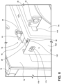
- the engagement element 22 extends from the engagement portion 18, away from the base 12, and through an access aperture 132 defined by the inner panel 74 of the door assembly 58. In this way, the engagement element 22 extends through the inner panel 74 such that the engagement element 22 and the aperture 24 are visible when the door assembly 58 is in the opened position, as illustrated in FIG. 6 .
- a width of the abutting elements 130A, 130B is greater than a width of the access aperture 132 such that the engagement element 22 may extend through the access aperture 132 while the abutting elements 130A, 130B engage the inner surface.
- the engagement element 22 extends into a receiving opening 136 defined by the outer housing 52 to engage the interlock system 82.
- the engagement element 22 is inserted into the outer housing 52 to engage the interlock system 82, such that the aperture 24 receives or engages the hook (e.g., the retaining element 84) of the rotating cam 86.
- the engagement element 22 moves further into the outer housing 52, causing the rotation of the rotating cam 86 and, consequently, activation of the interlock switch 88.
- the door hook 16 defines the first receiving aperture 20.
- the first receiving aperture 20 can be a top receiving aperture defined by the top surface 112 of the door hook 16.
- the first receiving aperture 20 is defined by the coupling portion 110 of the door hook 16 proximate to the abutting elements 130A, 130B.
- the first receiving aperture 20 may be a through-hole, a counterbore hole, a counter-sink hole, a spot-facing hole, or other similar aperture.
- the first receiving aperture 20 operably receives the door hook fastener 28, which may be the fixing screw or similar coupling member.
- the door hook 16 further defines either a threaded insert or threading defined on an inner wall surrounding the first receiving aperture 20 to mate with and engage the door hook fastener 28.
- the base 12 defines a corresponding receiving aperture 138 that may be configured to align with the first receiving aperture 20. In certain positions of the door hook 16, the door hook fastener 28 may extend into the corresponding receiving aperture 138. Further, the corresponding receiving aperture 138 may have a size that allows the door hook fastener 28 to extend therein when the door hook 16 is in multiple positions. Additionally, it is generally contemplated that the first receiving aperture 20 may be defined in various portions and surfaces of the door hook 16, without departing from the teachings herein.
- the door hook assembly 10 includes the adjustment assembly 26 for tuning or adjusting the position of the door hook 16 relative to the base 12, the door assembly 58, and the interlock system 82.
- the adjustment assembly 26 may be coupled to the base 12, the door assembly 58, and/or the door hook 16. In various examples, the adjustment assembly 26 may be coupled to the top surface 112 and/or the coupling portion 110 of the door hook 16.
- the adjustment assembly 26 is configured to tune and adjust a position of the door hook 16 relative to the door assembly 58 such that the breaking point between the door hook assembly 10 and the interlock system 82 may be adjusted.
- the adjustment assembly 26 is configured as an offset or eccentric screw 140 for driving the linear translation of the door hook 16 in response to rotation of the eccentric screw 140.
- the coupling portion 110 of the door hook 16 defines a second receiving aperture 142 for receiving the eccentric screw 140.
- the second receiving aperture 142 is a side receiving aperture that extends through the coupling portion 110, from a first side surface 144 of the coupling portion 110 to a second side surface 146 of the coupling portion 110 that opposes the first side surface 144.
- the second receiving aperture 142 permits insertion of the eccentric screw 140 through the coupling portion 110.
- the second receiving aperture 142 may be a blind hole extending from either the first side surface 144 or the second side surface 146.
- the second receiving aperture 142 may have a depth that allows for insertion of the eccentric screw 140 into the second receiving aperture 142. Accordingly, the second receiving aperture 142 extends generally normal to the first receiving aperture 20. In other aspects, the second receiving aperture 142 may extend parallel to or angled from the first receiving aperture 20. Additionally, it is generally contemplated that the second receiving aperture 142 may be defined in various locations of the door hook 16, without departing from the teachings herein.
- the second receiving aperture 142 may be a top receiving aperture, while the first receiving aperture 20 may be a side receiving aperture.
- the eccentric screw 140 is received or positioned in a first slot 150 and a second slot 152 defined by the base 12.
- the first side section 96 defines the first slot 150
- the second side section 98 defines the second slot 152, which is generally aligned with the first slot 150.
- the first slot 150 is configured to receive a proximal portion 154 of the eccentric screw 140
- the second slot 152 is configured to receive a distal portion 156 of the eccentric screw 140 on an opposing side of the door hook 16.
- the first slot 150 and the second slot 152 each have a width that is at least greater than a width of the proximal portion 154 and the distal portion 156, respectively.
- the second receiving aperture 142 may be defined in such a way that a middle portion 160 of the eccentric screw 140 is configured to be disposed within the door hook 16 to engage at least opposing portions 162A, 162B of an inner wall 164.
- the inner wall 164 is defined around an outer periphery of the second receiving aperture 142.
- the opposing portions 162A, 162B generally form inner and outer or front and rear portions of the inner wall 164.
- the second receiving aperture 142 may be defined in such a manner that the middle portion 160 of the eccentric screw 140 has a sliding engagement with the inner wall 164 and remains in contact with the inner wall 164 as the eccentric screw 140 rotates.
- the adjustment assembly 26 is configured as the eccentric screw 140 for tuning the position of the door hook 16 relative to the door assembly 58.
- the eccentric screw 140 is inserted through the first slot 150, the second receiving aperture 142, and the second slot 152.
- the eccentric screw 140 can be inserted through the side panel 76A, allowing rotation of the eccentric screw 140 from outside the door assembly 58, which is advantageous for adjusting the position of the door hook 16 during and after manufacturing processes.
- the proximal portion 154 of the eccentric screw 140 generally includes a screw head 170 that is configured to abut the side panel 76A or the first side section 96 when the eccentric screw 140 is fully inserted.
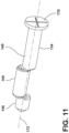
- the eccentric screw 140 also includes the distal portion 156 coaxial with the proximal portion 154 along a rotational axis 172, which is generally a central axis of the proximal and distal portions 154, 156 and the screw head 170.
- the proximal portion 154 is spaced from the distal portion 156 by the middle portion 160 disposed therebetween.
- the middle portion 160 is offset from the proximal portion 154 and the distal portion 156, being disposed partially along the rotational axis 172 but not coaxial with the proximal portion 154 and the distal portion 156. Accordingly, a central axis of the middle portion 160 is spaced from and parallel to the rotational axis 172.
- the offset middle portion 160 rotates around the rotational axis 172, with the offset nature of the middle portion 160 causing the engagement with the inner wall 164. In this way, this configuration allows for alignment of the door hook 16 via the eccentric screw 140 engaging and moving the door hook 16 as the eccentric screw 140 is rotated.
- the middle portion 160 may be entirely offset from the rotational axis 172 without departing from the teachings herein.
- the proximal portion 154 is partially disposed within the first slot 150 and extends between the first side section 96 of the base 12 and the first side surface 144 of the coupling portion 110.
- the distal portion 156 extends between the second side section 98 of the base 12 and the second side surface 146 of the door hook 16 such that the distal portion 156 is disposed within or proximate to the second slot 152.
- the distal portion 156 may include an additional element, such as a pin or a nut, that assists in retaining the proximal portion 154 and/or the distal portion 156 in respective positions.
- the middle portion 160 is generally disposed within the second receiving aperture 142 and is at least partially in contact with the inner wall 164 to drive movement of the door hook 16.
- the middle portion 160 of the eccentric screw 140 is in continuous contact with the inner wall 164.
- the offset relationship between the middle portion 160 compared to the proximal portion 154 and the distal portion 156 and the rotation of the eccentric screw 140 provides a cammed interface that exerts a force on the door hook 16, which causes linear translation of the door hook 16.
- the linear translation is relative to the fore-and-aft, or depth, of the door assembly 58.
- the rotational movement of the eccentric screw 140 is translated into linear motion of the door hook 16 through the camming engagement between the inner wall 164 and the middle portion 160 of the eccentric screw 140.
- the continuous contact between the eccentric screw 140 and the door hook 16 can move the door hook 16 in two opposing directions based on the rotational direction of the eccentric screw 140. For example, when the eccentric screw 140 is rotated clockwise, the door hook 16 may be moved in a first direction, such as towards the inner panel 74. When the eccentric screw 140 is rotated counterclockwise, the door hook 16 may be moved in a second direction, such as towards the outer panel 70. Based on the configuration of the eccentric screw 140 and the relationship between the eccentric screw 140 and the door hook 16, different rotation of the eccentric screw 140 can result in different linear movement of the door hook 16.
- the second receiving aperture 142 may be defined in such a manner that the eccentric screw 140 contacts the opposing portions 162A, 162B of the inner wall 164, which are generally front and rear portions to drive the fore-and-aft movement of the door hook 16.
- the inner wall 164 may define an oval or oblong shape where the eccentric screw 140 may be spaced from upper and lower portions of the inner wall 164 during rotation.
- the eccentric screw 140 may permit the translation of the door hook 16 once the middle portion 160 contacts either of the opposing portions 162A, 162B.
- the user may adjust a position of the door hook 16 relative to the base 12 and the inner panel 74.
- the eccentric screw 140 may contact various portions of the inner wall 164 and that the door hook 16 may move in a like direction of the portion of the inner wall 164 contacted, without departing from the teachings herein.
- the user may rotate the eccentric screw 140 about the rotational axis 172 via a driver or tool that engages the screw head 170.
- the driver may be a screwdriver
- the screw head 170 may define a cross-section that engages with an end of the screwdriver that has a like or mating design. It is also generally contemplated that the screw head 170 may have various designs, so long as the user can drive the rotational movement of the eccentric screw 140.
- the user may access the screw head 170 via an access opening 174 that is defined by the side panel 76A of the door assembly 58.
- the access opening 174 may have a width that is at least equal to or greater than a width of the screw head 170 to allow insertion of the eccentric screw 140 therethrough.
- the access opening 174 may have a width smaller than the screw head 170 and with a width to receive the driver to retain the eccentric screw 140 in the interior of the door assembly 58.
- the screw head 170 may be disposed outside of the side panel 76A for access to the screw head 170 with the eccentric screw 140 extending through the access opening 174.
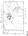
- the adjustment assembly 26 may be configured as a rack and pinion gear set 180 to tune the position of the door hook 16.
- the rack and pinion gear set 180 includes a pinion 182 rotatably coupled to the door assembly 58 via an intermediate shaft 184, and a rack 186 coupled to the door hook 16.
- the pinion 182 may be a normal spur gear or corrected spur gear with a teeth ratio that coincides with teeth of the rack 186.
- the rack 186 may be coupled to or integrally formed with the door hook 16, and the rack 186 may have a teeth ratio that coincides with teeth of the pinion 182.
- the rack and pinion gear set 180 may define various teeth ratios such that rotation of the pinion 182 at a single speed may drive a linear movement of the rack 186 and, consequently, linear movement of the door hook 16 at varying speeds, depending on the respective gear ratio between the rack and pinion gear set 180.
- the user may rotate the pinion 182 about a rotational axis 188 of the pinion 182 to adjust or tune the door hook 16.
- the rotational axis 188 may extend through a center point of the intermediate shaft 184 such that the pinion 182 is rotating about the intermediate shaft 184.
- the pinion 182 may be rotated, and the door hook 16 tuned, via a tool or driver, such as a screwdriver or Allen key, that can engage with a receiver 190 defined by the pinion 182.
- the user can apply a rotational force upon the pinion 182 with the tool.
- the receiver 190 may be accessed by opening the door assembly 58 and engaging with the pinion 182 via the access opening 174.
- a coupling feature may be coupled to the pinion 182 or the intermediate shaft 184 may extend through the pinion 182.
- the coupling feature or the intermediate shaft 184 may extend toward or through the access opening 174 to be engaged by the user.
- the pinion 182 may be rotated, and the door hook 16 tuned, by a user grasping the door hook 16 and applying a pushing or pulling force along a depth of the door assembly 58.
- the pushing or pulling of the door hook 16 permits translation of the door hook 16 as the rack 186 drives the pinion 182 and permits rotation of the pinion 182.
- the rack and pinion gear set 180 may include a stop, such as a pawl, or other stopping feature, that may inhibit rotation of the pinion 182 and/ortravel of the rack 186 and assist in keeping the door hook 16 in the tuned position while the door hook fastener 28 is being adjusted to the fixed condition.
- the adjustment assembly 26 may be configured as a biasing member 200 and at least one insert 202 to tune the position of the door hook 16.
- the biasing member 200 is illustrated as a spring 200 that is housed within the base 12 but may be any feature that exerts a biasing force.
- the spring 200 includes a first end 204 that contacts or is coupled to the first support section 92 and a second end 206 that contacts or is coupled to the door hook 16.
- the door hook 16 includes a protrusion 208 extending from a bottom portion 210 thereof, and the second end 206 of the spring 200 is coupled to the protrusion 208.
- the spring 200 may then provide a biasing force that drives or biases the door hook 16 towards the second support section 94.
- Each insert 202 may be disposed in the upper opening 14 of the base 12 and may be disposed between the coupling portion 110 of the door hook 16 and the second support section 94 of the base 12.
- each insert 202 may include opposing sides 212A, 212B.
- the opposing sides 212A, 212B may face the coupling portion 110 and the second support section 94, respectively, and have a width that is less than a defined width of the upper opening 14.
- the width may be greater than a width of the second opening 106 such that the insert 202 extends beyond edges that define the second opening 106 to abut the second support section 94. In this configuration, the insert 202 is maintained within the upper opening 14 of the base 12.
- the second opening 106 may be omitted from the second support section 94, and the insert 202 is then disposed between the coupling portion 110 of the door hook 16 and the second support section 94.
- One or both of the opposing sides 212A, 212B may define a textured surface.
- the textured surface of each side 212A, 212B of the insert 202 may increase friction between the insert 202 and another element, which may be the door hook 16, the base 12, or another insert 202.
- the textured surface may be a ribbed surface, a roughened surface, and/or a knurled surface that increases friction between the textured surface and another member.
- the increased friction provides a retaining or holding force that at least assists in retaining the insert 202 in position and/or in a static condition.
- one or both of the opposing sides 212A, 212B may define a smooth surface, such as a machined or formed surface, that decreases friction between the opposing sides 212A, 212B and another element.
- the smooth surface can assist in the insertion of the insert 202 into the upper opening 14 and between components, such as the door hook 16 and the base 12.
- a portion of each side 212A, 212B may be smooth for assisting with insertion and have textured portions for maintaining the position of the insert 202.
- each insert 202 may be constructed of various materials having various properties, such as a metal, a plastic, a composite, or a combination thereof.
- the inserts 202 may be used to provide an opposing force that linearly adjusts or tunes the door hook 16 against the biasing force provided by the biasing member 200. It is generally contemplated that multiple inserts 202 having the same or different physical properties may be used to adjust the door hook 16 against the biasing force. The different physical properties may include but are not limited to, smooth surfaces, textured surfaces, resistance to deformation, elastic deformation, compression, etc. In this way, inserts 202 with a combination of properties may be used to customize and tune the position of the door hook 16, as well as adjust the precision of the tuning of the door hook 16.
- the number, shape, and/or size of the inserts 202 adjusting the linear translation of the door hook 16 may adjust and tune the door hook 16 to varying degrees. Accordingly, larger inserts 202 or a plurality of inserts 202 may drive the door hook 16 further toward the first support section 92 against the biasing force of the biasing member 200 to a larger degree than a single or smaller insert 202.
- the biasing force adjusts the door hook 16 towards the second support section 94.
- the biasing force is configured to retain engagement between the door hook 16 and the insert 202. This configuration assists in retaining the insert 202 in position between the door hook 16 and the base 12 with the biasing force acting on the insert via the door hook 16.
- the insert 202 may be an angular or angled insert, such as a triangular or wedge insert 202.
- the depth of insertion of the insert 202 into the base 12 determines a distance between the coupling portion 110 of the door hook 16 and the second support section 94.
- the insert 202 is a triangular or wedge insert 202 and a thinner portion of the triangular insert is a leading edge being inserted, the distance between the coupling portion 110 and the second support section 94 increases as the insertion depth increases, as illustrated in FIG. 14 .
- the insert 202 may also be pyramidal, conical, frusto-conical, or similar shapes where one end is thicker or larger than the opposing end. Additionally, in such examples, the insert 202 may be constructed of a softer material that permits deformation at contact points between the insert 202 and the coupling portion 110 and/or second support section 94, such as a plastic having a low durometer.
- the door hook 16 may be adjusted via a plurality of inserts 202, where the addition of each insert 202 increases the distance between the coupling portion 110 and the second support section 94.
- the opposing sides 212A, 212B of each of the plurality of inserts 202 may be parallel such that each insert 202 may be side stacked upon or next to each other.
- the increase in side-stack thickness likewise corresponds to an increase in distance between the coupling portion 110 and the second support section 94 against the biasing force of the biasing member 200.
- the door hook 16 is fastened to the base 12 via the door hook fastener 28.
- the door hook fastener 28 is operable between the unfixed condition and the fixed condition.
- the door hook fastener 28 may be the fixing screw 28.
- the fixing screw 28 is in the unfixed condition when it is spaced from either the threaded insert or a threaded inner wall or not fully installed therein. In this way, When the fixing screw 28 is in the unfixed condition, the door hook 16 may freely translate along the base 12, and the position of the door hook 16 can be adjusted or tuned.
- the fixing screw 28 can be moved in the fixed condition when the screw rotates downward, into, or toward the base 12 about a rotational axis 220.
- the rotational axis 220 is generally perpendicular to the respective rotational axis 172, 188.
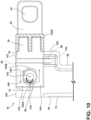
- the threading on the fixing screw 28 engages with either the threaded insert or the threaded inner wall of the door hook 16 and with threading defined on the base 12 (see FIGS. 9 and 10 ).
- the fixing screw 28 is in the fixed condition, the door hook 16 is fastened to the base 12 in a fixed position, where translation of the door hook 16 is minimized or prevented. This retains the door hook 16 in the selected position to determine the breaking point with the interlock system 82.
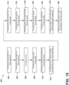
- a method 300 of manufacturing the cooking appliance 50 includes step 302 of forming an outer side of the door assembly 58 by coupling the outer panel 70 with the outer glass pane 72A.
- Step 304 includes forming an inner side of the door assembly 58 by coupling the inner panel 74 with the inner glass pane 72B.
- Step 304 may also include coupling the side panels 76A, 76B to the inner panel 74.
- step 304 can include forming the access opening 174 in the side panel 76A.
- step 306 the base 12 is provided with the upper opening 14.
- step 308 the door hook 16 is inserted into the upper opening 14 and supported by the base 12. In certain aspects, the door hook 16 is held in a generally horizontal position by the base 12. The door hook 16 is positioned for the engagement portion 18 to be positioned outside the base 12, and the coupling portion 110 to be positioned inside the base 12.
- the adjustment assembly 26 is coupled to the door hook 16 to form the door hook assembly 26 with the base 12.
- the eccentric screw 140 is inserted through the first slot 150, through the second receiving aperture 142, and/or through the second slot 152.
- the eccentric screw 140 may assist in retaining the door hook 16 in the horizontal position.
- a nut may be coupled to the eccentric screw 140 to retain the engagement between the eccentric screw 140 and the door hook 16.
- step 310 includes coupling the rack 186 to the door hook 16 and the pinion 182 to the intermediate shaft 184.
- the intermediate shaft 184 may be coupled to other components of the door assembly 58.
- the door hook 16 may be formed with the rack 186.
- the biasing member 200 may be coupled to the base 12 and the door hook 16 in step 310.
- the door hook 16 can be repositioned in the base 12 with the biasing force acting on the door hook 16.
- the inner frame 79 is formed, including the base 12 with the door hook 16 and the adjustment assembly 26 (e.g., the door hook assembly 10).
- the coupling of the various supports to form the inner frame 79 may generally retain the door hook assembly 10 in the inner frame 79.
- the inner frame 79 is coupled to the outer panel 70.
- the inner panel 74 and the side panels 76A, 76B are coupled to the outer panel 70 over the door hook assembly 10 and the inner frame 79.
- the engagement element 22 of the door hook 16 extends through the access aperture 132 defined by the inner panel 74.
- the inner frame 79 may be coupled to the inner panel 74 and/or the side panels 76A, 76B.
- Steps 302-318 may generally be a method for forming the door assembly 58.
- step 320 the interlock system 82 is coupled to the inner housing 54 and positioned in the outer housing 52.
- the outer housing 52 includes the receiving opening 136 to receive the engagement element 22.
- step 322 the door assembly 58 is coupled to the outer housing 52.
- step 324 the position of the door hook 16 is adjusted or tuned.
- the position of the door hook 16 can be adjusted by rotating the eccentric screw 140 (see FIGS. 6-11 ), rotating the pinion 182 (see FIG. 12 ), and/or by adding or removing inserts 202 between the door hook 16 and the base 12 (see FIGS. 13 and 14 ).
- the position of the door hook 16 can be tuned to minimize a distance that the door assembly 58 moves from the fully closed position to the breaking point for the interlock system 82.
- step 326 the fixing screw 28 is inserted into the first receiving aperture 20 to fix the door hook 16 in position relative to the base 12 and, consequently, the door assembly 58, as well as fix the relationship between the door hook 16 and the interlock system 82.
- the steps 302-326 of method 300 may be performed in any order, performed simultaneously, performed in succession, repeated, omitted, etc. without departing from the teachings herein. Further, a portion of the method 300 such as, but not limited to, steps 318-326 may be referred to as a method of tuning or adjusting the door hook 16.
- the interlock system 82 is disposed in the outer housing 52, and the door hook assembly 10 is disposed in the door assembly 58. It is also contemplated that the door hook assembly 10 may be positioned in the outer housing 52 while the interlock system 82 is disposed in the door, without departing from the teachings herein.
- the engagement element 22 extends out of the outer housing 52 and is configured to extend into the door assembly 58.
- the access opening 174 may be defined on the outer housing 52.
- the adjustment assembly 26 may be coupled to the outer housing 52 or the inner housing 54.
- the door hook assembly 10 provides the user with linear adjustability between the door assembly 58 and the interlock system 82.
- This linear adjustability can assist in adjusting the breaking point between the door hook assembly 10 and the interlock system 82 such that the breaking point occurs earlier to stop the electric current from traveling to the magnetron 80 or other heating elements and/or electronic components.
- the use of the adjustment assembly 26 provides the user with the opportunity to effectively adjust a position of the door hook 16 in the fore-and-aft direction relative to the door assembly 58.
- the user may be able to quickly adjust the position of the door hook 16 relative to the door assembly 58 by rotating the eccentric screw 140.
- the middle portion 160 may contact the inner wall 164 that encompasses the second receiving aperture 142 and exerts a force upon the door hook 16.
- the force exerted by the eccentric screw 140 can then drive the linear translation of the door hook 16 such that the position of the door hook 16 relative to door assembly 58 is tuned.
- the user may then fix the door hook 16 to the base 12 by moving the door hook fastener 28 from the unfixed condition to the fixed condition.
- the tuning may also be accomplished via the rack and pinion gear set 180 or the inserts 202 and fixed in a similar manner with the fixing screw 28.
- the linear adjustability of the door hook assembly 10 further provides for greater variance in tolerances, and tolerance stacking of various components of the microwave oven 50.
- the door hook 16 of the door hook assembly 10 may be linearly adjusted and tuned relative to the interlock system 82 after other aspects of the microwave oven 50 have been assembled and/or after a manufacturing process for the cooking appliance 50 is complete.
- Minimal components, including a portion of the inner frame 79 may be removed to adjust the fixing screw 28 to the unfixed condition to tune the door hook 16.
- the door hook assembly 10 may be coupled to and disposed within the outer housing 52 and may engage with the interlock system 82 disposed within the door assembly 58.
- the use of at least one of the eccentric screw 140, the rack and pinion gear set 180, and/or the biasing member 200 and the insert 202 allows for a quick and efficient adjustment of the door hook 16 to define the closed position of the door assembly 58.
- the linear adjustment provided by the door hook assembly 10 advantageously allows the user to linearly adjust and redefine the closed position after other aspects of the microwave oven 50 have been assembled, which in turn allows for greater variance in tolerances and tolerance stacking.
- the position of the door hook 16 can be tuned multiple times, including after completion of the manufacturing process.
- the tuning of the position of the door hook 16 can minimize the movement of the door assembly 58 between the fully closed position and the breaking point for the interlock system 82. Additional benefits or advantages of using this device may also be realized and/or achieved.
- the device disclosed herein is further summarized in the following paragraphs and is further characterized by combinations of any and all of the various aspects described therein.
- a door hook assembly for a cooking appliance includes a base that defines an opening.
- a door hook is disposed within the opening.
- the door hook includes an engagement portion and defines a first receiving aperture.
- the engagement portion includes an engagement element that defines an aperture.
- An adjustment assembly is coupled to the door hook.
- the adjustment assembly is configured to drive a linear translation of the door hook.
- a door hook fastener is disposed within the first receiving aperture.
- the door hook fastener is movable between an unfixed condition and a fixed condition.
- the door hook is linearly translatable relative to the base when the door hook is in the unfixed condition.
- the door hook is fixed to the base when the door hook is in the fixed condition.
- the door hook defines a second receiving aperture.
- the adjustment assembly includes an eccentric screw disposed in the second receiving aperture. A rotational movement of the eccentric screw drives linear translation of the door hook.
- the eccentric screw includes a proximal portion having a screw head, a distal portion coaxial with the proximal portion along a first axis, and a middle portion between and offset from the proximal portion and the distal portion.
- the door hook includes an inner sidewall surrounding an outer periphery of the second receiving aperture.
- a middle portion operably contacts opposing portions of the inner sidewall during rotation to drive linear translation of the door hook.
- the adjustment assembly includes a rack and pinion gear set.
- the rack and pinion gear set includes a rack coupled to the door hook and a pinion operably coupled to the rack.
- a rotational movement of the pinion about a first axis drives linear translation of the door hook via engagement with the rack.
- the door hook fastener is movable between an unfixed condition and a fixed condition along a second axis.
- the second axis is generally perpendicular to a first axis.
- the adjustment assembly includes a biasing member disposed within a base and an insert disposed between a coupling portion of a door hook and a second support section of the base.
- the biasing member is coupled to the door hook and provides a biasing force that biases the door hook towards the second support section.
- the insert provides an opposing force that drives the door hook towards a first support section of the base.
- the door hook includes an engagement portion having a pair of outwardly extending abutting elements.
- the abutting elements are substantially perpendicular relative to the engagement element and are configured to limit the linear translation of the door hook.
- the first receiving aperture is defined on a top surface of the door hook.
- the first receiving aperture is defined on a side surface of the door hook.
- a cooking appliance includes an outer housing defining a receiving opening and an interlock system disposed within the outer housing proximate to the receiving opening.
- the interlock system includes a rotating cam and an interlock switch.
- a door assembly is operably coupled to the outer housing.
- the door assembly includes an inner panel defining an access aperture and a base operably coupled to the inner panel.
- the base defines an upper opening.
- the door assembly also includes a door hook disposed in the upper opening of the base and an adjustment assembly operably coupled to the door hook.
- the adjustment assembly is configured to linearly translate the door hook relative to the inner panel to adjust a position of the door hook. The position of the door hook adjusts an engagement between the door hook and the interlock system.
- the door hook is configured to rotate the rotating cam to engage the interlock switch when the door assembly is in a closed position.
- the door hook is configured to rotate the rotating cam to disengage from the interlock switch as the door assembly is moved to an opened position.
- a magnetron is configured to generate microwaves.
- a point of disengagement between the interlock switch and the rotating cam defines a breaking point for stopping power to the magnetron.
- a position of the door hook determines the breaking point.
- the adjustment assembly includes an eccentric screw having an offset portion.
- the eccentric screw extends through the door hook. Rotation of the eccentric screw is configured to drive a linear translation of the door hook.
- the adjustment assembly includes a rack coupled to the door hook and a pinion operably coupled to the door assembly. Rotation of the pinion drives movement of the rack and, consequently, a linear translation of the door hook.
- the adjustment assembly includes a biasing member extending between the door hook and a first support section of a base.
- the adjustment assembly further includes an insert configured to be positioned between a second support section of the base and the door hook to drive a linear translation of the door hook against a biasing force.
- the door assembly includes a fixing fastener configured to extend through the door hook and fix a position of the door hook relative to the base and, consequently, set a relationship between the door hook and the interlock system.
- a position of the door hook determines a distance of movement of the door assembly from a closed position to an opened position that causes disengagement between the interlock switch and the rotating cam to affect operation of the cooking appliance.
- a cooking appliance includes a housing, an interlock system disposed within the housing, a door assembly including an inner panel defining an access aperture, and a door hook assembly operably coupled to the door assembly.
- the door hook assembly includes a base defining an upper opening and a door hook positioned within the upper opening.
- the door hook includes an engagement element configured to extend into the housing to engage the interlock system when the door assembly is in a closed position.
- the door hook assembly also includes an adjustment assembly operably coupled to the door hook.
- the adjustment assembly is configured to drive linear translation of the door hook to adjust a position of the door hook relative to the base. The position of the door hook adjusts a relationship between the door hook and an interlock switch as the door assembly is moved from the closed position to an opened position.
- the interlock system includes a rotating cam and an interlock switch.
- the engagement element of the door hook is configured to rotate the rotating cam to engage the interlock switch as the door assembly moves to a closed position.
- the engagement element of the door hook is configured to rotate the rotating cam to disengage from the interlock switch as the door assembly is moved to an opened position.
- a relationship between the door hook and the interlock switch as the door assembly is moved from the closed position to the opened position determines a point where the interlock switch is adjusted to stop power to a magnetron.
- the door hook includes a coupling portion disposed on the base, an engagement portion disposed between the base and the inner panel, and the engagement element extending from the engagement portion.
- the adjustment assembly is operably coupled to the coupling portion.
- the engagement portion is moved between abutting the inner panel and abutting the base to define a range of movement for the door hook.
- the adjustment assembly includes at least one of an eccentric screw, a rack and pinion gear set, and a biasing member and an insert.
- a door hook assembly for a cooking appliance includes a base defining an opening and a door hook disposed within the opening.
- the door hook has an engagement portion and a coupling portion.
- the door hook defines a receiving aperture.
- the engagement portion includes an engagement element configured to engage an interlock system of a cooking appliance.
- the door hook assembly also includes an adjustment assembly operably coupled to the door hook and that is configured to drive a linear translation of the door hook and a door hook fastener selectively disposed within the receiving aperture.
- the door hook fastener is movable between an unfixed condition and a fixed condition.
- the door hook is linearly translatable relative to the base when the door hook fastener is in the unfixed condition.
- the door hook is fixed to the base when the door hook fastener is in the fixed condition.
- the door hook defines a second receiving aperture.
- the adjustment assembly includes an eccentric screw disposed in the second receiving aperture. A rotational movement of the eccentric screw drives the linear translation of the door hook.
- the eccentric screw includes a proximal portion having a screw head, a distal portion coaxial with the proximal portion along a rotational axis, and a middle portion between and offset from the proximal portion and the distal portion.
- the adjustment assembly includes a rack and pinion gear set.
- the rack and pinion gear set includes a rack coupled to the door hook and a pinion operably coupled to the rack.
- a rotational movement of the pinion about a rotational axis drives a linear translation of the door hook via engagement with the rack.
- the adjustment assembly includes a biasing member disposed within the base between the door hook and a first support section of the base and an insert disposed between the coupling portion of the door hook and a second support section of the base.
- the biasing member provides a biasing force that biases the door hook towards the second support section.
- the insert provides an opposing force that drives the door hook toward the first support section of the base.
- the engagement portion includes outwardly extending abutting elements.
- the outwardly extending abutting elements are perpendicular relative to an engagement element and are configured to limit a linear translation of a door hook.
- a cooking appliance comprises an outer housing defining a receiving opening.
- An interlock system is disposed within the outer housing proximate to the receiving opening.
- the interlock system includes a rotating cam and an interlock switch.
- a door assembly is operably coupled to the outer housing.
- the door assembly includes: an inner panel defining an access aperture, a base operably coupled to the inner panel.
- the base defines an upper opening.
- a door hook is disposed in the upper opening of the base.
- An adjustment assembly is operably coupled to the door hook.
- the adjustment assembly is configured to linearly translate the door hook relative to the inner panel to adjust a position of the door hook.
- the position of the door hook adjusts an engagement between the door hook and the interlock system.
- the door hook includes an engagement portion and a coupling portion.
- the engagement portion includes an engagement element configured to extend into the outer housing to engage the interlock system when the door assembly is in a closed position.
- the engagement element of the door hook is configured to rotate the rotating cam to engage the interlock switch as the door assembly moves to the closed position.
- the engagement element of the door hook is configured to rotate the rotating cam to disengage from the interlock switch as the door assembly is moved to an opened position.
- a magnetron is configured to generate microwaves.
- a point of disengagement between the interlock switch and the rotating cam defines a breaking point for stopping power to the magnetron.
- the position of the door hook determines the breaking point.
- the door hook includes a coupling portion disposed on the base, an engagement portion disposed between the base and the inner panel, and an engagement element extending from the engagement portion.
- the adjustment assembly is operably coupled to the coupling portion.
- the engagement portion is moved between abutting the inner panel and abutting the base to define a range of movement for the door hook.
- the engagement portion includes outwardly extending abutting elements.
- the outwardly extending abutting elements are configured to limit linear translation of the door hook.
- the outwardly extending abutting elements are perpendicular relative to the engagement element.
- the door assembly includes a fixing fastener configured to extend through the door hook and fix the position of the door hook relative to the base and, consequently, set a relationship between the door hook and the interlock system.
- the door hook defines a receiving aperture.
- the fixing fastener is selectively disposed within the receiving aperture.
- the fixing fastener is movable between an unfixed condition and a fixed condition.
- the door hook is linearly translatable relative to the base when the fixing fastener is in the unfixed condition and is fixed to the base when the fixing fastener is in the fixed condition.
- the position of the door hook determines a distance of movement of the door assembly from a closed position to an opened position that causes disengagement between the interlock switch and the rotating cam to affect operation of said cooking appliance.
- the door hook defines a receiving aperture.
- the adjustment assembly includes an eccentric screw that is disposed in the receiving aperture and extends through the door hook.
- the eccentric screw includes a proximal portion having a screw head, a distal portion coaxial with the proximal portion along a rotational axis, and a middle portion between and offset from the proximal portion and the distal portion.
- a rotation of the eccentric screw is configured to drive linear translation of the door hook.
- the adjustment assembly includes a rack coupled to the door hook and a pinion operably coupled to the door assembly.
- a rotation of the pinion drives movement of the rack and, consequently, linear translation of the door hook.
- the adjustment assembly includes a biasing member extending between the door hook and a first support section of the base.
- the adjustment assembly further includes an insert configured to be positioned between a second support section of the base and the door hook to drive linear translation of the door hook against a biasing force.
- the term "coupled” in all of its forms, couple, coupling, coupled, etc. generally means the joining of two components (electrical or mechanical) directly or indirectly to one another. Such joining may be stationary in nature or movable in nature. Such joining may be achieved with the two components (electrical or mechanical) and any additional intermediate members being integrally formed as a single unitary body with one another or with the two components. Such joining may be permanent in nature or may be removable or releasable in nature unless otherwise stated.
Landscapes
- Physics & Mathematics (AREA)
- Electromagnetism (AREA)
- Engineering & Computer Science (AREA)
- Chemical & Material Sciences (AREA)
- Combustion & Propulsion (AREA)
- Mechanical Engineering (AREA)
- General Engineering & Computer Science (AREA)
- Electric Ovens (AREA)
Abstract
Description
- The present disclosure generally relates to an adjustable door hook assembly, and more specifically, to an adjustable door hook assembly for a microwave.
- According to one aspect of the present disclosure, a cooking appliance includes an outer housing defining a receiving aperture and an interlock system disposed within the outer housing proximate to the interlock system. The interlock system includes a rotating cam and an interlock switch. A door assembly is operably coupled to the outer housing. The door assembly includes an inner panel defining an access aperture and a base operably coupled to the inner panel. The base defines an upper opening. The door assembly also includes a door hook disposed in the upper opening of the base and an adjustment assembly operably coupled to the door hook. The adjustment assembly is configured to linearly translate the door hook relative to the inner panel to adjust a position of the door hook. The position of the door hook adjusts an engagement between the door hook and the interlock system.
- According to an aspect of the present disclosure, a cooking appliance includes a housing, an interlock system disposed within the housing, a door assembly including an inner panel defining an access aperture, and a door hook assembly operably coupled to the door assembly. The door hook assembly includes a base defining an upper opening and a door hook positioned within the upper opening. The door hook includes an engagement element configured to extend into the housing to engage the interlock system when the door assembly is in a closed position. The door hook assembly also includes an adjustment assembly operably coupled to the door hook. The adjustment assembly is configured to drive linear translation of the door hook to adjust a position of the door hook relative to the base. The position of the door hook adjusts a relationship between the door hook and an interlock switch as the door assembly is moved from the closed position to an opened position.
- According to an aspect of the present disclosure, a door hook assembly for a cooking appliance includes a base defining an opening and a door hook disposed within the opening. The door hook has an engagement portion and a coupling portion. The door hook defines a receiving aperture. The engagement portion includes an engagement element configured to engage an interlock system of a cooking appliance. The door hook assembly also includes an adjustment assembly operably coupled to the door hook and that is configured to drive a linear translation of the door hook and a door hook fastener selectively disposed within the receiving aperture. The door hook fastener is movable between an unfixed condition and a fixed condition. The door hook is linearly translatable relative to the base when the door hook fastener is in the unfixed condition. The door hook is fixed to the base when the door hook fastener is in the fixed condition.
- These and other features, advantages, and objects of the present disclosure will be further understood and appreciated by those skilled in the art by reference to the following specification, claims, and appended drawings.
- In the drawings:
-
FIG. 1A is a side perspective view of a cooking appliance with a door assembly in a closed position and a button for opening the door assembly, according to the present disclosure; -
FIG. 1B is a side perspective view of a cooking appliance with a door assembly in a closed position and a handle, according to the present disclosure; -
FIG. 2 is a side perspective view of a door assembly for a cooking appliance with a door hook assembly, according to the present disclosure; -
FIG. 3 is a partially exploded side perspective view of a door assembly for a cooking appliance with a door hook assembly, according to the present disclosure; -
FIG. 4 is a top plan view of a door hook assembly on a door assembly and an interlock system in a cooking appliance with the door assembly in an opened position, according to the present disclosure; -
FIG. 5 is a top plan view of the door hook assembly ofFIG. 2 engaging the interlock system with the door assembly in a closed position, according to the present disclosure; -
FIG. 6 is a partial side perspective view of a door assembly with a door hook assembly, according to the present disclosure; -
FIG. 7 is a partial side perspective view of a door hook assembly with an adjustment assembly, according to the present disclosure; -
FIG. 8 is a partial side perspective view of a door hook assembly with an adjustment assembly configured as an eccentric screw, according to the present disclosure; -
FIG. 9 is an exploded partial side perspective view of a door hook assembly with an adjustment assembly configured as an eccentric screw, according to the present disclosure; -
FIG. 10 is a partial side elevational view of a door hook assembly with an adjustment assembly configured as an eccentric screw, according to the present disclosure; -
FIG. 11 is a side perspective view of an eccentric screw for an adjustment assembly for a door hook assembly, according to the present disclosure; -
FIG. 12 is a partial side perspective view of a door assembly for a cooking appliance with a door hook assembly that has an adjustment assembly configured as a rack and pinion gear set, according to the present disclosure; -
FIG. 13 is a partial side perspective view of a door assembly for a cooking appliance with a door hook assembly that has an adjustment assembly including an insert, according to the present disclosure; -
FIG. 14 is a partial side elevational view of a door assembly for a cooking appliance with a door hook assembly that has an adjustment assembly configured as a biasing member and an insert, according to the present disclosure; and -
FIG. 15 is a flow diagram of a method of manufacturing a cooking appliance with a door hook assembly, according to the present disclosure. - The components in the figures are not necessarily to scale, emphasis instead being placed upon illustrating the principles described herein.
- The present illustrated embodiments reside primarily in combinations of method steps and apparatus components related to a door hook assembly. Accordingly, the apparatus components and method steps have been represented, where appropriate, by conventional symbols in the drawings, showing only those specific details that are pertinent to understanding the embodiments of the present disclosure so as not to obscure the disclosure with details that will be readily apparent to those of ordinary skill in the art having the benefit of the description herein. Further, like numerals in the description and drawings represent like elements.
- For purposes of description herein, the terms "upper," "lower," "right," "left," "rear," "front," "vertical," "horizontal," and derivatives thereof shall relate to the disclosure as oriented in
FIG. 1 . Unless stated otherwise, the term "front" shall refer to the surface of the element closer to an intended viewer, and the term "rear" shall refer to the surface of the element further from the intended viewer. However, it is to be understood that the disclosure may assume various alternative orientations, except where expressly specified to the contrary. It is also to be understood that the specific devices and processes illustrated in the attached drawings and described in the following specification are simply exemplary embodiments of the inventive concepts defined in the appended claims. Hence, specific dimensions and other physical characteristics relating to the embodiments disclosed herein are not to be considered as limiting, unless the claims expressly state otherwise. - The terms "including," "comprises," "comprising," or any other variation thereof, are intended to cover a non-exclusive inclusion, such that a process, method, article, or apparatus that comprises a list of elements does not include only those elements but may include other elements not expressly listed or inherent to such process, method, article, or apparatus. An element preceded by "comprises a ..." does not, without more constraints, preclude the existence of additional identical elements in the process, method, article, or apparatus that comprises the element.
- Referring to
FIGS. 1A-15 ,reference numeral 10 generally designates a door hook assembly that includes abase 12 defining anupper opening 14. Adoor hook 16 is supported by thebase 12 and extends through theupper opening 14. Thedoor hook 16 includes anengagement portion 18, and thedoor hook 16 also defines afirst receiving aperture 20. Theengagement portion 18 includes anengagement element 22 extending from theengagement portion 18, and theengagement element 22 defines anaperture 24. - The
door hook assembly 10 includes anadjustment assembly 26 operably coupled to thedoor hook 16. Theadjustment assembly 26 is configured to drive or promote linear translation of thedoor hook 16. Adoor hook fastener 28 or fixingfastener 28 is selectively disposed within the first receivingaperture 20. Thedoor hook fastener 28 is movable between an unfixed condition, where thedoor hook 16 is linearly translatable relative to thebase 12, and a fixed condition, resulting in thedoor hook 16 being fixed to the base 12 or in a static condition where movement of thedoor hook 16 is reduced or prevented. - Referring still to
FIG. 1A , thedoor hook assembly 10 is included in acooking appliance 50, which may be an oven, a microwave oven, a convection oven, a steam oven, a conventional oven, or other cooking apparatus. In the illustrated example ofFIG. 1A , thecooking appliance 50 is amicrowave oven 50 that includes anouter housing 52, as well as aninner housing 54 that is positioned within theouter housing 52 and that defines acooking cavity 56. - The
microwave oven 50 includes adoor assembly 58 that selectively closes and provides access to thecooking cavity 56 to allow for the placement and removal of items to be heated or cooked into and from thecooking cavity 56. Thedoor assembly 58 inFIG. 1A rotates about a vertical rotational axis. Additionally, in the example illustrated inFIG. 1A , themicrowave oven 50 is provided with acontrol panel 60, which is illustrated adjacent to thedoor assembly 58. Thecontrol panel 60 generally includes auser interface 62, which may include one or more input elements, such as push buttons, touch switches, and the like for setting operation parameters for controlling themicrowave oven 50. - With reference to
FIG. 1B , an additional configuration of themicrowave oven 50 is illustrated. This configuration of themicrowave oven 50 includes theouter housing 52 and thedoor assembly 58 operably coupled to theouter housing 52. Thedoor assembly 58 is configured to rotate about a horizontal rotational axis to raise and close thecooking cavity 56 and lower and close thecooking cavity 56. Thedoor assembly 58 includes ahandle 78 to allow a user to move thedoor assembly 58. Themicrowave oven 50 also includes thecontrol panel 60, which may be on thedoor assembly 58 or on theouter housing 52 proximate to thedoor assembly 58, such as above thedoor assembly 58. - Referring to
FIGS. 2 and3 , thedoor assembly 58 may include anouter panel 70, outer andinner glass panes inner panel 74, andside panels outer panel 70 is coupled with theouter glass pane 72A, and theinner panel 74 is coupled with theinner glass pane 72B. Theside panels outer panel 70 and theinner panel 74 such that thepanels door assembly 58. - The
glass panes cooking cavity 56 may be visible to a user through theglass panes door assembly 58 by pressing apush button 77, such as in the configuration illustrated inFIG. 1A , or by pulling on ahandle 78 attached to or defined by thedoor assembly 58, such as in the configuration illustrated inFIG. 1B . To close thedoor assembly 58, the user may push thedoor assembly 58 until thedoor assembly 58 is in a closed position. Thedoor assembly 58 is generally retained closed by a latch or latch assembly. - The
door assembly 58 also includes aninner frame 79 disposed within the interior, which can provide additional structural support for thedoor assembly 58 and components of thedoor assembly 58. For example, as illustrated inFIG. 3 , theinner frame 79 includes multiple supports that couple to one another to form a generally rectangular shape extending about a perimeter of theglass panes cooking cavity 56. Theinner frame 79 can also provide support for theadjustment assembly 26. In the illustrated configuration, the base 12 forms a side support of theinner frame 79. It is also contemplated that theadjustment assembly 26 can be included in or form any portion of theinner frame 79 without departing from the teachings herein. - The illustrated configurations of the
door assembly 58 are merely illustrative, with it being understood that various configurations of thedoor assembly 58 are possible without departing from the teachings herein. Similarly, the configuration of theouter housing 52 and the portions of thecooking cavity 56 not specifically discussed herein can vary according to the principles discussed herein and to accommodate the various features described in further detail herein. - With reference again to
FIGS. 1A and1B , as well asFIGS. 4 and 5 , themicrowave oven 50 includes cooking or heating components and electronic components, such as amagnetron 80 for generating, directing, etc. microwaves. Themicrowave oven 50 may include any electronic components for generating microwaves or may include any components for heating or cooking food items. The microwaves are generally contained within themicrowave oven 50, with minimal or no microwave emissions outside of or around themicrowave oven 50. For example, microwave emissions around themicrowave oven 50 may be less than about 5 mW/cm2 or less than about 1 mW/cm2. When themicrowave oven 50 is operating (e.g., generating microwaves), the user can open thedoor assembly 58, which stops the generation of microwaves. This stopping is generally accomplished by a relationship between thedoor hook assembly 10 and aninterlock system 82. - Referring still to
FIGS. 4 and 5 , theinterlock system 82 is disposed within theouter housing 52 and may be supported by theinner housing 54 above thecooking cavity 56. Thedoor hook assembly 10 operably engages with theinterlock system 82. When thedoor assembly 58 is in the closed position, thedoor hook assembly 10 is engaged with theinterlock system 82 and when thedoor assembly 58 is in an opened position, thedoor hook assembly 10 is disengaged from theinterlock system 82. The state of theinterlock system 82 affects the operation of themagnetron 80 as described herein. - The
interlock system 82 may include a retainingelement 84, such as a hook, on a rotatingcam 86. Theengagement element 22 of thedoor hook assembly 10 is configured to latch or engage with the retainingelement 84 and cause the rotatingcam 86 to rotate based on movement of thedoor hook assembly 10 that results from movement of thedoor assembly 58. The rotatingcam 86 is rotated to engage with or disengage from aninterlock switch 88. Accordingly, when theinterlock switch 88 is closed, such that a circuit is closed, an electric current may travel to themagnetron 80, powering themagnetron 80 to generate microwaves. When theinterlock system 82 is decoupled or disengaged from thedoor hook assembly 10, the rotatingcam 86 is rotated away from theinterlock switch 88 and, consequently, disengages from theinterlock switch 88. Accordingly, in this state, theinterlock switch 88 is open, such that the circuit is open and the electric current may be hindered or prevented from traveling to themagnetron 80, reducing or preventing power from themagnetron 80 and stopping the generation of microwaves. In this way, when thedoor assembly 58 is opened, power is generally prevented from reaching themagnetron 80. It is also contemplated that a door pin may also be used to directly engage theinterlock switch 88 without departing from the teachings herein. - The closed position of the
door assembly 58 and, as a result, the activated state of themagnetron 80, may be defined by an engagement between thedoor hook assembly 10 and theinterlock system 82. As thedoor assembly 58 moves from the closed position to the opened position, a breaking point occurs when the rotatingcam 86 disengages from the interlock switch 88 (i.e., a point of disengagement), where theinterlock switch 88 changes status to stop the power to themagnetron 80. The breaking point is generally the last moment in which theinterlock switch 88 changes from closed (e.g., providing power to the magnetron 80) to opened (e.g., stopping power to the magnetron 80) during movement of thedoor assembly 58 from the closed position to the opened position. Accordingly, there is a certain amount of distance thedoor assembly 58 moves before the breaking point occurs. Thedoor hook assembly 10 can minimize this distance and range of motion of thedoor assembly 58 to cause the breaking point based on a position of thedoor hook 16 and, consequently, the relationship between thedoor hook assembly 10 and theinterlock system 82, which affects operation of themagnetron 80 and themicrowave oven 50 as described herein. - As the
door hook assembly 10 decouples or disengages from theinterlock system 82, theinterlock switch 88 transitions from closed to open. In certain aspects where thedoor assembly 58 is configured with the push button 77 (seeFIG. 1A ) and theinterlock system 82 includes the rotatingcam 86, theinterlock switch 88 may open before thedoor hook assembly 10 completely disengages with theinterlock system 82. In such aspects, the act of pressing thepush button 77 may cause the rotatingcam 86 to rotate and disengage with theinterlock switch 88, causing theinterlock switch 88 to open before the retainingelement 84 disengages from thedoor hook assembly 10. The disengaging of theinterlock switch 88 before the disengagement between the retainingelement 84 and thedoor hook assembly 10 is such that electric current is prevented from traveling to themagnetron 80 before thedoor hook assembly 10 completely disengages from theinterlock system 82 and, consequently, before thedoor assembly 58 is opened. - In additional or alternative aspects, where the
door assembly 58 is configured with the handle 78 (seeFIG. 1B ) to open thedoor assembly 58, theinterlock switch 88 may open as thedoor hook assembly 10 disengages with theinterlock system 82. In such aspects, the act of pulling thehandle 78 may cause thedoor hook assembly 10 to disengage with the retainingelement 84 as theinterlock switch 88 opens. The opening of theinterlock switch 88, as thedoor assembly 58 opens, is such that electric current is prevented from traveling to the heating element as thedoor hook assembly 10 disengages from theinterlock system 82. - To allow the
interlock system 82 to disengage from thedoor hook assembly 10 and theinterlock switch 88 to open as thedoor assembly 58 begins to open, a fore-and-aft position of thedoor hook 16 relative to thedoor assembly 58 may be tuned or adjusted such that the breaking point occurs with minimal or minimized movement of thedoor assembly 58 toward the opened position. In other words, the position of thedoor hook assembly 10 can be adjusted to adjust the breaking point to be as close as possible to the fully closed position of thedoor assembly 58, where the fully closed position generally includes the rotatingcam 86 being at a maximum rotation and thedoor assembly 58 abutting theouter housing 52. - Referring now to
FIGS. 6-14 , thebase 12 is coupled to thedoor assembly 58 to form a portion of theinner frame 79. In various examples, thebase 12 can be coupled to thedoor assembly 58 via fasteners, coupling members, interlocking features, adhesive, etc. In various configurations, thebase 12 may be also coupled to theinner panel 74 and/or theside panel 76A of thedoor assembly 58 in a similar manner. Thebase 12 is illustrated adjacent to theside panel 76A but may be positioned adjacent to the opposingside panel 76B without departing from the teachings herein. - In the illustrated example, the
base 12 is disposed in the interior of thedoor assembly 58 between theinner panel 74 and theouter panel 70 in acorner 90 defined at the intersection of theinner panel 74 and theside panel 76A. The base 12 generally includes an inner orfirst support section 92 oriented toward theinner panel 74 and an outer orsecond support section 94 opposing thefirst support section 92 and oriented toward theouter panel 70. The base 12 also includes afirst side section 96 oriented toward theside panel 76A and extending between the first andsecond support sections second side section 98 opposing thefirst side section 96, where thesecond side section 98 is oriented toward theside panel 76B and extends between the first andsecond support sections - A
top edge 100 of thebase 12 defines theupper opening 14 to receive thedoor hook 16. At least one or multiple of thesections upper opening 14 without departing from the teachings herein. Thedoor hook 16 is inserted into thebase 12 via theupper opening 14. Thedoor hook 16 is partially positioned within thebase 12 via theupper opening 14 and at least partially extends out of thebase 12. - As illustrated in
FIG. 6 , thefirst support section 92 abuts theinner panel 74 of thedoor assembly 58, and thefirst side section 96 abuts theside panel 76A of thedoor assembly 58. In various examples, thefirst support section 92 may have a protrudingsegment 102 that abuts theinner panel 74. Thefirst support section 92 defines afirst opening 104 through which thedoor hook 16 extends. Thesecond support section 94 defines asecond opening 106 that is aligned with thefirst opening 104 and may also be configured to receive thedoor hook 16. Thedoor hook 16 can extend out of the interior of thebase 12 via one or both of the first andsecond openings second openings door hook 16 relative to thebase 12 and, consequently, thedoor assembly 58. - The
door hook 16 includes theengagement portion 18 and acoupling portion 110, which collectively form atop surface 112 of thedoor hook 16. Theengagement portion 18 includes abuttingelements coupling portion 110. The abuttingelements door hook 16 while maximizing efficiency of the manufacturing process. - The
engagement element 22 extends from theengagement portion 18 and away from thecoupling portion 110. Theengagement element 22 and thecoupling portion 110 are generally aligned with a center portion of theengagement portion 18, forming a general "t" or plus ("+") shape of thedoor hook 16. In this way, the abuttingelements engagement element 22 and thecoupling portion 110. - The abutting
elements segment 102 of thefirst support section 92 as thedoor hook 16 is translated towards and/or past the second support section 94 (e.g., towards or through the second opening 106). The contact between the protrudingsegment 102 and the abuttingelements door hook 16 in a direction towards theouter panel 70, defining a limit or range to the movement of thedoor hook 16. Further, thefirst support section 92 and theside section 96 define a receivingrecess 134 where theabutting element 130A is positioned when the abuttingelements first support section 92. - In various examples, the abutting
elements first support section 92 and are configured to contact an inner surface of theinner panel 74 as thedoor hook 16 is translated towards and/or past thefirst support section 92. The contact between the inner surface and the abuttingelements door hook 16 in a direction toward theinner panel 74. In certain aspects, this defined limit or movement provided by the contact between the abuttingelements segment 102 and an inner surface of theinner panel 74 serves to provide a translational range in which thedoor hook 16 may be tuned while still allowing engagement with theinterlock system 82 in a manner that rotates the rotatingcam 86 to engage theinterlock switch 88. - The
engagement element 22 extends from theengagement portion 18, away from thebase 12, and through anaccess aperture 132 defined by theinner panel 74 of thedoor assembly 58. In this way, theengagement element 22 extends through theinner panel 74 such that theengagement element 22 and theaperture 24 are visible when thedoor assembly 58 is in the opened position, as illustrated inFIG. 6 . Generally, a width of the abuttingelements access aperture 132 such that theengagement element 22 may extend through theaccess aperture 132 while the abuttingelements - According to various aspects, as the
door assembly 58 is moved to the closed position, theengagement element 22 extends into a receivingopening 136 defined by theouter housing 52 to engage theinterlock system 82. Theengagement element 22 is inserted into theouter housing 52 to engage theinterlock system 82, such that theaperture 24 receives or engages the hook (e.g., the retaining element 84) of the rotatingcam 86. As thedoor assembly 58 closes, theengagement element 22 moves further into theouter housing 52, causing the rotation of the rotatingcam 86 and, consequently, activation of theinterlock switch 88. - Referring still to
FIGS. 6-11 , thedoor hook 16 defines the first receivingaperture 20. As illustrated, the first receivingaperture 20 can be a top receiving aperture defined by thetop surface 112 of thedoor hook 16. Generally, the first receivingaperture 20 is defined by thecoupling portion 110 of thedoor hook 16 proximate to the abuttingelements first receiving aperture 20 may be a through-hole, a counterbore hole, a counter-sink hole, a spot-facing hole, or other similar aperture. Thefirst receiving aperture 20 operably receives thedoor hook fastener 28, which may be the fixing screw or similar coupling member. - In such examples, the
door hook 16 further defines either a threaded insert or threading defined on an inner wall surrounding the first receivingaperture 20 to mate with and engage thedoor hook fastener 28. Further, thebase 12 defines acorresponding receiving aperture 138 that may be configured to align with the first receivingaperture 20. In certain positions of thedoor hook 16, thedoor hook fastener 28 may extend into the corresponding receivingaperture 138. Further, the corresponding receivingaperture 138 may have a size that allows thedoor hook fastener 28 to extend therein when thedoor hook 16 is in multiple positions. Additionally, it is generally contemplated that the first receivingaperture 20 may be defined in various portions and surfaces of thedoor hook 16, without departing from the teachings herein. - The
door hook assembly 10 includes theadjustment assembly 26 for tuning or adjusting the position of thedoor hook 16 relative to thebase 12, thedoor assembly 58, and theinterlock system 82. Theadjustment assembly 26 may be coupled to thebase 12, thedoor assembly 58, and/or thedoor hook 16. In various examples, theadjustment assembly 26 may be coupled to thetop surface 112 and/or thecoupling portion 110 of thedoor hook 16. Theadjustment assembly 26 is configured to tune and adjust a position of thedoor hook 16 relative to thedoor assembly 58 such that the breaking point between thedoor hook assembly 10 and theinterlock system 82 may be adjusted. - Referring still to
FIGS. 6-11 , in various aspects, theadjustment assembly 26 is configured as an offset oreccentric screw 140 for driving the linear translation of thedoor hook 16 in response to rotation of theeccentric screw 140. Thecoupling portion 110 of thedoor hook 16 defines asecond receiving aperture 142 for receiving theeccentric screw 140. As illustrated inFIGS. 7-10 , thesecond receiving aperture 142 is a side receiving aperture that extends through thecoupling portion 110, from afirst side surface 144 of thecoupling portion 110 to asecond side surface 146 of thecoupling portion 110 that opposes thefirst side surface 144. Thesecond receiving aperture 142 permits insertion of theeccentric screw 140 through thecoupling portion 110. - In certain aspects, the
second receiving aperture 142 may be a blind hole extending from either thefirst side surface 144 or thesecond side surface 146. In such examples, thesecond receiving aperture 142 may have a depth that allows for insertion of theeccentric screw 140 into thesecond receiving aperture 142. Accordingly, thesecond receiving aperture 142 extends generally normal to the first receivingaperture 20. In other aspects, thesecond receiving aperture 142 may extend parallel to or angled from the first receivingaperture 20. Additionally, it is generally contemplated that thesecond receiving aperture 142 may be defined in various locations of thedoor hook 16, without departing from the teachings herein. For example, thesecond receiving aperture 142 may be a top receiving aperture, while the first receivingaperture 20 may be a side receiving aperture. - As illustrated in
FIGS. 7 and8 , theeccentric screw 140 is received or positioned in afirst slot 150 and asecond slot 152 defined by thebase 12. In various examples, thefirst side section 96 defines thefirst slot 150, and thesecond side section 98 defines thesecond slot 152, which is generally aligned with thefirst slot 150. Thefirst slot 150 is configured to receive aproximal portion 154 of theeccentric screw 140, and thesecond slot 152 is configured to receive adistal portion 156 of theeccentric screw 140 on an opposing side of thedoor hook 16. Accordingly, thefirst slot 150 and thesecond slot 152 each have a width that is at least greater than a width of theproximal portion 154 and thedistal portion 156, respectively. - In various examples, the
second receiving aperture 142 may be defined in such a way that amiddle portion 160 of theeccentric screw 140 is configured to be disposed within thedoor hook 16 to engage at least opposingportions inner wall 164. Theinner wall 164 is defined around an outer periphery of thesecond receiving aperture 142. The opposingportions inner wall 164. Thesecond receiving aperture 142 may be defined in such a manner that themiddle portion 160 of theeccentric screw 140 has a sliding engagement with theinner wall 164 and remains in contact with theinner wall 164 as theeccentric screw 140 rotates. - In the example illustrated in
FIGS. 6-11 , theadjustment assembly 26 is configured as theeccentric screw 140 for tuning the position of thedoor hook 16 relative to thedoor assembly 58. Theeccentric screw 140 is inserted through thefirst slot 150, thesecond receiving aperture 142, and thesecond slot 152. Often, theeccentric screw 140 can be inserted through theside panel 76A, allowing rotation of theeccentric screw 140 from outside thedoor assembly 58, which is advantageous for adjusting the position of thedoor hook 16 during and after manufacturing processes. - The
proximal portion 154 of theeccentric screw 140 generally includes ascrew head 170 that is configured to abut theside panel 76A or thefirst side section 96 when theeccentric screw 140 is fully inserted. Theeccentric screw 140 also includes thedistal portion 156 coaxial with theproximal portion 154 along arotational axis 172, which is generally a central axis of the proximal anddistal portions screw head 170. Theproximal portion 154 is spaced from thedistal portion 156 by themiddle portion 160 disposed therebetween. - The
middle portion 160 is offset from theproximal portion 154 and thedistal portion 156, being disposed partially along therotational axis 172 but not coaxial with theproximal portion 154 and thedistal portion 156. Accordingly, a central axis of themiddle portion 160 is spaced from and parallel to therotational axis 172. The offsetmiddle portion 160 rotates around therotational axis 172, with the offset nature of themiddle portion 160 causing the engagement with theinner wall 164. In this way, this configuration allows for alignment of thedoor hook 16 via theeccentric screw 140 engaging and moving thedoor hook 16 as theeccentric screw 140 is rotated. Moreover, themiddle portion 160 may be entirely offset from therotational axis 172 without departing from the teachings herein. - As illustrated in
FIGS. 7-9 , theproximal portion 154 is partially disposed within thefirst slot 150 and extends between thefirst side section 96 of thebase 12 and thefirst side surface 144 of thecoupling portion 110. Thedistal portion 156 extends between thesecond side section 98 of thebase 12 and thesecond side surface 146 of thedoor hook 16 such that thedistal portion 156 is disposed within or proximate to thesecond slot 152. In some examples, thedistal portion 156 may include an additional element, such as a pin or a nut, that assists in retaining theproximal portion 154 and/or thedistal portion 156 in respective positions. Themiddle portion 160 is generally disposed within thesecond receiving aperture 142 and is at least partially in contact with theinner wall 164 to drive movement of thedoor hook 16. - In various examples, the
middle portion 160 of theeccentric screw 140 is in continuous contact with theinner wall 164. In such examples, the offset relationship between themiddle portion 160 compared to theproximal portion 154 and thedistal portion 156 and the rotation of theeccentric screw 140 provides a cammed interface that exerts a force on thedoor hook 16, which causes linear translation of thedoor hook 16. The linear translation is relative to the fore-and-aft, or depth, of thedoor assembly 58. The rotational movement of theeccentric screw 140 is translated into linear motion of thedoor hook 16 through the camming engagement between theinner wall 164 and themiddle portion 160 of theeccentric screw 140. - In certain aspects, the continuous contact between the
eccentric screw 140 and thedoor hook 16 can move thedoor hook 16 in two opposing directions based on the rotational direction of theeccentric screw 140. For example, when theeccentric screw 140 is rotated clockwise, thedoor hook 16 may be moved in a first direction, such as towards theinner panel 74. When theeccentric screw 140 is rotated counterclockwise, thedoor hook 16 may be moved in a second direction, such as towards theouter panel 70. Based on the configuration of theeccentric screw 140 and the relationship between theeccentric screw 140 and thedoor hook 16, different rotation of theeccentric screw 140 can result in different linear movement of thedoor hook 16. - In additional non-limiting examples, the
second receiving aperture 142 may be defined in such a manner that theeccentric screw 140 contacts the opposingportions inner wall 164, which are generally front and rear portions to drive the fore-and-aft movement of thedoor hook 16. In such examples, theinner wall 164 may define an oval or oblong shape where theeccentric screw 140 may be spaced from upper and lower portions of theinner wall 164 during rotation. Theeccentric screw 140 may permit the translation of thedoor hook 16 once themiddle portion 160 contacts either of the opposingportions middle portion 160 and theinner wall 164, the user may adjust a position of thedoor hook 16 relative to thebase 12 and theinner panel 74. Additionally, it is generally contemplated that theeccentric screw 140 may contact various portions of theinner wall 164 and that thedoor hook 16 may move in a like direction of the portion of theinner wall 164 contacted, without departing from the teachings herein. - To tune the position of the
door hook 16 via theeccentric screw 140, the user may rotate theeccentric screw 140 about therotational axis 172 via a driver or tool that engages thescrew head 170. In various examples, the driver may be a screwdriver, and thescrew head 170 may define a cross-section that engages with an end of the screwdriver that has a like or mating design. It is also generally contemplated that thescrew head 170 may have various designs, so long as the user can drive the rotational movement of theeccentric screw 140. - In various examples, the user may access the
screw head 170 via an access opening 174 that is defined by theside panel 76A of thedoor assembly 58. Theaccess opening 174 may have a width that is at least equal to or greater than a width of thescrew head 170 to allow insertion of theeccentric screw 140 therethrough. However, the access opening 174 may have a width smaller than thescrew head 170 and with a width to receive the driver to retain theeccentric screw 140 in the interior of thedoor assembly 58. Additionally or alternatively, thescrew head 170 may be disposed outside of theside panel 76A for access to thescrew head 170 with theeccentric screw 140 extending through theaccess opening 174. - Referring to
FIG. 12 , theadjustment assembly 26 may be configured as a rack and pinion gear set 180 to tune the position of thedoor hook 16. In various examples, the rack and pinion gear set 180 includes apinion 182 rotatably coupled to thedoor assembly 58 via anintermediate shaft 184, and arack 186 coupled to thedoor hook 16. Thepinion 182 may be a normal spur gear or corrected spur gear with a teeth ratio that coincides with teeth of therack 186. Therack 186 may be coupled to or integrally formed with thedoor hook 16, and therack 186 may have a teeth ratio that coincides with teeth of thepinion 182. Additionally, the rack and pinion gear set 180 may define various teeth ratios such that rotation of thepinion 182 at a single speed may drive a linear movement of therack 186 and, consequently, linear movement of thedoor hook 16 at varying speeds, depending on the respective gear ratio between the rack and pinion gear set 180. - The user may rotate the
pinion 182 about arotational axis 188 of thepinion 182 to adjust or tune thedoor hook 16. In various examples, therotational axis 188 may extend through a center point of theintermediate shaft 184 such that thepinion 182 is rotating about theintermediate shaft 184. Thepinion 182 may be rotated, and thedoor hook 16 tuned, via a tool or driver, such as a screwdriver or Allen key, that can engage with areceiver 190 defined by thepinion 182. The user can apply a rotational force upon thepinion 182 with the tool. In such examples, thereceiver 190 may be accessed by opening thedoor assembly 58 and engaging with thepinion 182 via theaccess opening 174. - Additionally or alternatively, a coupling feature may be coupled to the
pinion 182 or theintermediate shaft 184 may extend through thepinion 182. In such examples, the coupling feature or theintermediate shaft 184 may extend toward or through the access opening 174 to be engaged by the user. - In further non-limiting examples, the
pinion 182 may be rotated, and thedoor hook 16 tuned, by a user grasping thedoor hook 16 and applying a pushing or pulling force along a depth of thedoor assembly 58. In such examples, the pushing or pulling of thedoor hook 16 permits translation of thedoor hook 16 as therack 186 drives thepinion 182 and permits rotation of thepinion 182. Additionally, it is also contemplated that once tuning has been completed, the rack and pinion gear set 180 may include a stop, such as a pawl, or other stopping feature, that may inhibit rotation of thepinion 182 and/ortravel of therack 186 and assist in keeping thedoor hook 16 in the tuned position while thedoor hook fastener 28 is being adjusted to the fixed condition. - Referring to
FIGS. 13 and14 , theadjustment assembly 26 may be configured as a biasingmember 200 and at least oneinsert 202 to tune the position of thedoor hook 16. The biasingmember 200 is illustrated as aspring 200 that is housed within thebase 12 but may be any feature that exerts a biasing force. Thespring 200 includes afirst end 204 that contacts or is coupled to thefirst support section 92 and asecond end 206 that contacts or is coupled to thedoor hook 16. In the illustrated example, thedoor hook 16 includes aprotrusion 208 extending from abottom portion 210 thereof, and thesecond end 206 of thespring 200 is coupled to theprotrusion 208. Thespring 200 may then provide a biasing force that drives or biases thedoor hook 16 towards thesecond support section 94. - Each
insert 202 may be disposed in theupper opening 14 of thebase 12 and may be disposed between thecoupling portion 110 of thedoor hook 16 and thesecond support section 94 of thebase 12. In various examples, eachinsert 202 may include opposingsides coupling portion 110 and thesecond support section 94, respectively, and have a width that is less than a defined width of theupper opening 14. In additional examples, the width may be greater than a width of thesecond opening 106 such that theinsert 202 extends beyond edges that define thesecond opening 106 to abut thesecond support section 94. In this configuration, theinsert 202 is maintained within theupper opening 14 of thebase 12. Additionally, in various examples, thesecond opening 106 may be omitted from thesecond support section 94, and theinsert 202 is then disposed between thecoupling portion 110 of thedoor hook 16 and thesecond support section 94. - One or both of the opposing
sides side insert 202 may increase friction between theinsert 202 and another element, which may be thedoor hook 16, thebase 12, or anotherinsert 202. By way of example, not limitation, the textured surface may be a ribbed surface, a roughened surface, and/or a knurled surface that increases friction between the textured surface and another member. In such examples, the increased friction provides a retaining or holding force that at least assists in retaining theinsert 202 in position and/or in a static condition. - In additional non-limiting examples, one or both of the opposing
sides sides insert 202 into theupper opening 14 and between components, such as thedoor hook 16 and thebase 12. Moreover, a portion of eachside insert 202. Additionally, it is generally contemplated that eachinsert 202 may be constructed of various materials having various properties, such as a metal, a plastic, a composite, or a combination thereof. - Referring still to
FIGS. 13 and14 , theinserts 202 may be used to provide an opposing force that linearly adjusts or tunes thedoor hook 16 against the biasing force provided by the biasingmember 200. It is generally contemplated thatmultiple inserts 202 having the same or different physical properties may be used to adjust thedoor hook 16 against the biasing force. The different physical properties may include but are not limited to, smooth surfaces, textured surfaces, resistance to deformation, elastic deformation, compression, etc. In this way, inserts 202 with a combination of properties may be used to customize and tune the position of thedoor hook 16, as well as adjust the precision of the tuning of thedoor hook 16. - It is also generally contemplated that the number, shape, and/or size of the
inserts 202 adjusting the linear translation of thedoor hook 16 may adjust and tune thedoor hook 16 to varying degrees. Accordingly,larger inserts 202 or a plurality ofinserts 202 may drive thedoor hook 16 further toward thefirst support section 92 against the biasing force of the biasingmember 200 to a larger degree than a single orsmaller insert 202. Upon removal of theinsert 202 or inserts 202, the biasing force adjusts thedoor hook 16 towards thesecond support section 94. Moreover, the biasing force is configured to retain engagement between thedoor hook 16 and theinsert 202. This configuration assists in retaining theinsert 202 in position between thedoor hook 16 and the base 12 with the biasing force acting on the insert via thedoor hook 16. - In various aspects, such as the configuration illustrated in
FIG. 14 , theinsert 202 may be an angular or angled insert, such as a triangular orwedge insert 202. In such examples, the depth of insertion of theinsert 202 into thebase 12 determines a distance between thecoupling portion 110 of thedoor hook 16 and thesecond support section 94. For example, if theinsert 202 is a triangular orwedge insert 202 and a thinner portion of the triangular insert is a leading edge being inserted, the distance between thecoupling portion 110 and thesecond support section 94 increases as the insertion depth increases, as illustrated inFIG. 14 . Theinsert 202 may also be pyramidal, conical, frusto-conical, or similar shapes where one end is thicker or larger than the opposing end. Additionally, in such examples, theinsert 202 may be constructed of a softer material that permits deformation at contact points between theinsert 202 and thecoupling portion 110 and/orsecond support section 94, such as a plastic having a low durometer. - In additional non-limiting examples, the
door hook 16 may be adjusted via a plurality ofinserts 202, where the addition of eachinsert 202 increases the distance between thecoupling portion 110 and thesecond support section 94. For example, the opposingsides inserts 202 may be parallel such that eachinsert 202 may be side stacked upon or next to each other. The increase in side-stack thickness likewise corresponds to an increase in distance between thecoupling portion 110 and thesecond support section 94 against the biasing force of the biasingmember 200. - Referring again to
FIGS. 6-14 , once the position of thedoor hook 16 has been tuned by theadjustment assembly 26 to a select position, thedoor hook 16 is fastened to thebase 12 via thedoor hook fastener 28. Thedoor hook fastener 28 is operable between the unfixed condition and the fixed condition. In various examples, thedoor hook fastener 28 may be the fixingscrew 28. The fixingscrew 28 is in the unfixed condition when it is spaced from either the threaded insert or a threaded inner wall or not fully installed therein. In this way, When the fixingscrew 28 is in the unfixed condition, thedoor hook 16 may freely translate along thebase 12, and the position of thedoor hook 16 can be adjusted or tuned. - The fixing
screw 28 can be moved in the fixed condition when the screw rotates downward, into, or toward the base 12 about arotational axis 220. In the illustrated configurations, therotational axis 220 is generally perpendicular to the respectiverotational axis screw 28 engages with either the threaded insert or the threaded inner wall of thedoor hook 16 and with threading defined on the base 12 (seeFIGS. 9 and10 ). When the fixingscrew 28 is in the fixed condition, thedoor hook 16 is fastened to the base 12 in a fixed position, where translation of thedoor hook 16 is minimized or prevented. This retains thedoor hook 16 in the selected position to determine the breaking point with theinterlock system 82. - With reference to
FIG. 15 , as well asFIGS. 1A-14 , amethod 300 of manufacturing thecooking appliance 50 includesstep 302 of forming an outer side of thedoor assembly 58 by coupling theouter panel 70 with theouter glass pane 72A. Step 304 includes forming an inner side of thedoor assembly 58 by coupling theinner panel 74 with theinner glass pane 72B. Step 304 may also include coupling theside panels inner panel 74. Further, step 304 can include forming the access opening 174 in theside panel 76A. - In
step 306, thebase 12 is provided with theupper opening 14. Instep 308, thedoor hook 16 is inserted into theupper opening 14 and supported by thebase 12. In certain aspects, thedoor hook 16 is held in a generally horizontal position by thebase 12. Thedoor hook 16 is positioned for theengagement portion 18 to be positioned outside thebase 12, and thecoupling portion 110 to be positioned inside thebase 12. - In
step 310, theadjustment assembly 26 is coupled to thedoor hook 16 to form thedoor hook assembly 26 with thebase 12. In certain aspects, such as for the configuration illustrated inFIGS. 6-11 , theeccentric screw 140 is inserted through thefirst slot 150, through thesecond receiving aperture 142, and/or through thesecond slot 152. Theeccentric screw 140 may assist in retaining thedoor hook 16 in the horizontal position. Further, instep 310, a nut may be coupled to theeccentric screw 140 to retain the engagement between theeccentric screw 140 and thedoor hook 16. - In additional or alternative aspects, such as the configuration illustrated in
FIG. 12 ,step 310 includes coupling therack 186 to thedoor hook 16 and thepinion 182 to theintermediate shaft 184. Theintermediate shaft 184 may be coupled to other components of thedoor assembly 58. Further, thedoor hook 16 may be formed with therack 186. - In further non-limiting examples, such as the configuration illustrated in
FIGS. 13 and14 , the biasingmember 200 may be coupled to thebase 12 and thedoor hook 16 instep 310. Thedoor hook 16 can be repositioned in the base 12 with the biasing force acting on thedoor hook 16. - In
step 312, theinner frame 79 is formed, including the base 12 with thedoor hook 16 and the adjustment assembly 26 (e.g., the door hook assembly 10). The coupling of the various supports to form theinner frame 79 may generally retain thedoor hook assembly 10 in theinner frame 79. Instep 314, theinner frame 79 is coupled to theouter panel 70. Instep 316, theinner panel 74 and theside panels outer panel 70 over thedoor hook assembly 10 and theinner frame 79. Instep 318, theengagement element 22 of thedoor hook 16 extends through theaccess aperture 132 defined by theinner panel 74. Further, theinner frame 79 may be coupled to theinner panel 74 and/or theside panels door assembly 58. - In
step 320, theinterlock system 82 is coupled to theinner housing 54 and positioned in theouter housing 52. Theouter housing 52 includes the receivingopening 136 to receive theengagement element 22. Instep 322, thedoor assembly 58 is coupled to theouter housing 52. - In
step 324, the position of thedoor hook 16 is adjusted or tuned. The position of thedoor hook 16 can be adjusted by rotating the eccentric screw 140 (seeFIGS. 6-11 ), rotating the pinion 182 (seeFIG. 12 ), and/or by adding or removinginserts 202 between thedoor hook 16 and the base 12 (seeFIGS. 13 and14 ). The position of thedoor hook 16 can be tuned to minimize a distance that thedoor assembly 58 moves from the fully closed position to the breaking point for theinterlock system 82. - In
step 326, the fixingscrew 28 is inserted into the first receivingaperture 20 to fix thedoor hook 16 in position relative to thebase 12 and, consequently, thedoor assembly 58, as well as fix the relationship between thedoor hook 16 and theinterlock system 82. The steps 302-326 ofmethod 300 may be performed in any order, performed simultaneously, performed in succession, repeated, omitted, etc. without departing from the teachings herein. Further, a portion of themethod 300 such as, but not limited to, steps 318-326 may be referred to as a method of tuning or adjusting thedoor hook 16. - As described herein, the
interlock system 82 is disposed in theouter housing 52, and thedoor hook assembly 10 is disposed in thedoor assembly 58. It is also contemplated that thedoor hook assembly 10 may be positioned in theouter housing 52 while theinterlock system 82 is disposed in the door, without departing from the teachings herein. In such examples, theengagement element 22 extends out of theouter housing 52 and is configured to extend into thedoor assembly 58. In such examples, the access opening 174 may be defined on theouter housing 52. Theadjustment assembly 26 may be coupled to theouter housing 52 or theinner housing 54. - Referring to
FIGS. 1A-15 , thedoor hook assembly 10 provides the user with linear adjustability between thedoor assembly 58 and theinterlock system 82. This linear adjustability can assist in adjusting the breaking point between thedoor hook assembly 10 and theinterlock system 82 such that the breaking point occurs earlier to stop the electric current from traveling to themagnetron 80 or other heating elements and/or electronic components. - In particular, the use of the
adjustment assembly 26 provides the user with the opportunity to effectively adjust a position of thedoor hook 16 in the fore-and-aft direction relative to thedoor assembly 58. By way of example, the user may be able to quickly adjust the position of thedoor hook 16 relative to thedoor assembly 58 by rotating theeccentric screw 140. As theeccentric screw 140 rotates, themiddle portion 160 may contact theinner wall 164 that encompasses thesecond receiving aperture 142 and exerts a force upon thedoor hook 16. The force exerted by theeccentric screw 140 can then drive the linear translation of thedoor hook 16 such that the position of thedoor hook 16 relative todoor assembly 58 is tuned. Once the user has tuned the position of thedoor hook 16, the user may then fix thedoor hook 16 to thebase 12 by moving thedoor hook fastener 28 from the unfixed condition to the fixed condition. The tuning may also be accomplished via the rack and pinion gear set 180 or theinserts 202 and fixed in a similar manner with the fixingscrew 28. - The linear adjustability of the
door hook assembly 10 further provides for greater variance in tolerances, and tolerance stacking of various components of themicrowave oven 50. For example, thedoor hook 16 of thedoor hook assembly 10 may be linearly adjusted and tuned relative to theinterlock system 82 after other aspects of themicrowave oven 50 have been assembled and/or after a manufacturing process for thecooking appliance 50 is complete. Minimal components, including a portion of theinner frame 79 may be removed to adjust the fixingscrew 28 to the unfixed condition to tune thedoor hook 16. Additionally, it also contemplated that while thedoor hook assembly 10 is provided in thedoor assembly 58, thedoor hook assembly 10 may be coupled to and disposed within theouter housing 52 and may engage with theinterlock system 82 disposed within thedoor assembly 58. - Use of the presently disclosed device may provide a variety of advantages. For example, the use of at least one of the
eccentric screw 140, the rack and pinion gear set 180, and/or the biasingmember 200 and theinsert 202 allows for a quick and efficient adjustment of thedoor hook 16 to define the closed position of thedoor assembly 58. Additionally, the linear adjustment provided by thedoor hook assembly 10 advantageously allows the user to linearly adjust and redefine the closed position after other aspects of themicrowave oven 50 have been assembled, which in turn allows for greater variance in tolerances and tolerance stacking. Further, the position of thedoor hook 16 can be tuned multiple times, including after completion of the manufacturing process. Moreover, the tuning of the position of thedoor hook 16 can minimize the movement of thedoor assembly 58 between the fully closed position and the breaking point for theinterlock system 82. Additional benefits or advantages of using this device may also be realized and/or achieved. - The device disclosed herein is further summarized in the following paragraphs and is further characterized by combinations of any and all of the various aspects described therein.
- According to a first aspect of the present disclosure, a door hook assembly for a cooking appliance includes a base that defines an opening. A door hook is disposed within the opening. The door hook includes an engagement portion and defines a first receiving aperture. The engagement portion includes an engagement element that defines an aperture. An adjustment assembly is coupled to the door hook. The adjustment assembly is configured to drive a linear translation of the door hook. A door hook fastener is disposed within the first receiving aperture. The door hook fastener is movable between an unfixed condition and a fixed condition. The door hook is linearly translatable relative to the base when the door hook is in the unfixed condition. The door hook is fixed to the base when the door hook is in the fixed condition.
- In a second aspect according to the first aspect, the door hook defines a second receiving aperture. The adjustment assembly includes an eccentric screw disposed in the second receiving aperture. A rotational movement of the eccentric screw drives linear translation of the door hook.
- In a third aspect according to the second aspect, the eccentric screw includes a proximal portion having a screw head, a distal portion coaxial with the proximal portion along a first axis, and a middle portion between and offset from the proximal portion and the distal portion.
- In a fourth aspect according to the second aspect or third aspect, the door hook includes an inner sidewall surrounding an outer periphery of the second receiving aperture. A middle portion operably contacts opposing portions of the inner sidewall during rotation to drive linear translation of the door hook.
- In a fifth aspect according to the first aspect, the adjustment assembly includes a rack and pinion gear set. The rack and pinion gear set includes a rack coupled to the door hook and a pinion operably coupled to the rack. A rotational movement of the pinion about a first axis drives linear translation of the door hook via engagement with the rack.
- In a sixth aspect according to the fifth aspect, the door hook fastener is movable between an unfixed condition and a fixed condition along a second axis. The second axis is generally perpendicular to a first axis.
- In a seventh aspect according to the first aspect, the adjustment assembly includes a biasing member disposed within a base and an insert disposed between a coupling portion of a door hook and a second support section of the base. The biasing member is coupled to the door hook and provides a biasing force that biases the door hook towards the second support section. The insert provides an opposing force that drives the door hook towards a first support section of the base.
- In an eighth aspect according to any of the preceding aspects, the door hook includes an engagement portion having a pair of outwardly extending abutting elements. The abutting elements are substantially perpendicular relative to the engagement element and are configured to limit the linear translation of the door hook.
- In a ninth aspect according to any of the preceding aspects, the first receiving aperture is defined on a top surface of the door hook.
- In a tenth aspect according to any of the preceding aspects, the first receiving aperture is defined on a side surface of the door hook.
- According to an eleventh aspect of the present disclosure, a cooking appliance includes an outer housing defining a receiving opening and an interlock system disposed within the outer housing proximate to the receiving opening. The interlock system includes a rotating cam and an interlock switch. A door assembly is operably coupled to the outer housing. The door assembly includes an inner panel defining an access aperture and a base operably coupled to the inner panel. The base defines an upper opening. The door assembly also includes a door hook disposed in the upper opening of the base and an adjustment assembly operably coupled to the door hook. The adjustment assembly is configured to linearly translate the door hook relative to the inner panel to adjust a position of the door hook. The position of the door hook adjusts an engagement between the door hook and the interlock system.
- In a twelfth aspect according to the eleventh aspect, the door hook is configured to rotate the rotating cam to engage the interlock switch when the door assembly is in a closed position. The door hook is configured to rotate the rotating cam to disengage from the interlock switch as the door assembly is moved to an opened position.
- In a thirteenth aspect according to the eleventh aspect or twelfth aspect, a magnetron is configured to generate microwaves. A point of disengagement between the interlock switch and the rotating cam defines a breaking point for stopping power to the magnetron. A position of the door hook determines the breaking point.
- In a fourteenth aspect according to any of aspects eleven to thirteen, the adjustment assembly includes an eccentric screw having an offset portion. The eccentric screw extends through the door hook. Rotation of the eccentric screw is configured to drive a linear translation of the door hook.
- In a fifteenth aspect according to any of aspects eleven to thirteen, the adjustment assembly includes a rack coupled to the door hook and a pinion operably coupled to the door assembly. Rotation of the pinion drives movement of the rack and, consequently, a linear translation of the door hook.
- In a sixteenth aspect according to any of aspects eleven to thirteen, the adjustment assembly includes a biasing member extending between the door hook and a first support section of a base. The adjustment assembly further includes an insert configured to be positioned between a second support section of the base and the door hook to drive a linear translation of the door hook against a biasing force.
- In an seventeenth aspect according to any of aspects eleven to sixteen, the door assembly includes a fixing fastener configured to extend through the door hook and fix a position of the door hook relative to the base and, consequently, set a relationship between the door hook and the interlock system.
- In a eighteenth aspect according to any of aspects eleven to seventeen, a position of the door hook determines a distance of movement of the door assembly from a closed position to an opened position that causes disengagement between the interlock switch and the rotating cam to affect operation of the cooking appliance.
- According to a nineteenth aspect of the present disclosure, a cooking appliance includes a housing, an interlock system disposed within the housing, a door assembly including an inner panel defining an access aperture, and a door hook assembly operably coupled to the door assembly. The door hook assembly includes a base defining an upper opening and a door hook positioned within the upper opening. The door hook includes an engagement element configured to extend into the housing to engage the interlock system when the door assembly is in a closed position. The door hook assembly also includes an adjustment assembly operably coupled to the door hook. The adjustment assembly is configured to drive linear translation of the door hook to adjust a position of the door hook relative to the base. The position of the door hook adjusts a relationship between the door hook and an interlock switch as the door assembly is moved from the closed position to an opened position.
- In a twentieth aspect according to the nineteenth aspect, the interlock system includes a rotating cam and an interlock switch. The engagement element of the door hook is configured to rotate the rotating cam to engage the interlock switch as the door assembly moves to a closed position. The engagement element of the door hook is configured to rotate the rotating cam to disengage from the interlock switch as the door assembly is moved to an opened position.
- In a twenty-first aspect according to the twentieth aspect, a relationship between the door hook and the interlock switch as the door assembly is moved from the closed position to the opened position determines a point where the interlock switch is adjusted to stop power to a magnetron.
- In a twenty-second aspect according to any of aspects nineteen to twenty-first, the door hook includes a coupling portion disposed on the base, an engagement portion disposed between the base and the inner panel, and the engagement element extending from the engagement portion. The adjustment assembly is operably coupled to the coupling portion.
- In a twenty-third aspect according to aspect twenty-second, the engagement portion is moved between abutting the inner panel and abutting the base to define a range of movement for the door hook.
- In a twenty-fourth aspect according to any of aspects eleven to twenty-three, the adjustment assembly includes at least one of an eccentric screw, a rack and pinion gear set, and a biasing member and an insert.
- According to a twenty-fifth aspect of the present disclosure, a door hook assembly for a cooking appliance includes a base defining an opening and a door hook disposed within the opening. The door hook has an engagement portion and a coupling portion. The door hook defines a receiving aperture. The engagement portion includes an engagement element configured to engage an interlock system of a cooking appliance. The door hook assembly also includes an adjustment assembly operably coupled to the door hook and that is configured to drive a linear translation of the door hook and a door hook fastener selectively disposed within the receiving aperture. The door hook fastener is movable between an unfixed condition and a fixed condition. The door hook is linearly translatable relative to the base when the door hook fastener is in the unfixed condition. The door hook is fixed to the base when the door hook fastener is in the fixed condition.
- In a twenty-sixth aspect according to the twenty-fifth aspect, the door hook defines a second receiving aperture. The adjustment assembly includes an eccentric screw disposed in the second receiving aperture. A rotational movement of the eccentric screw drives the linear translation of the door hook.
- In a twenty-seventh aspect according to the twenty-sixth aspect, the eccentric screw includes a proximal portion having a screw head, a distal portion coaxial with the proximal portion along a rotational axis, and a middle portion between and offset from the proximal portion and the distal portion.
- In a twenty-eighth aspect according to the twenty-seventh aspect, the adjustment assembly includes a rack and pinion gear set. The rack and pinion gear set includes a rack coupled to the door hook and a pinion operably coupled to the rack. A rotational movement of the pinion about a rotational axis drives a linear translation of the door hook via engagement with the rack.
- In a twenty-ninth aspect according to the twenty-eighth aspect, the adjustment assembly includes a biasing member disposed within the base between the door hook and a first support section of the base and an insert disposed between the coupling portion of the door hook and a second support section of the base. The biasing member provides a biasing force that biases the door hook towards the second support section. The insert provides an opposing force that drives the door hook toward the first support section of the base.
- In a thirtieth aspect according to any of the aspects twenty-five to twenty-nine, the engagement portion includes outwardly extending abutting elements. The outwardly extending abutting elements are perpendicular relative to an engagement element and are configured to limit a linear translation of a door hook.
- According to a thirty-first aspect of the present disclosure, a cooking appliance comprises an outer housing defining a receiving opening. An interlock system is disposed within the outer housing proximate to the receiving opening. The interlock system includes a rotating cam and an interlock switch. A door assembly is operably coupled to the outer housing.
- In a thirty-second aspect according to the thirty-first aspect, the door assembly includes: an inner panel defining an access aperture, a base operably coupled to the inner panel. The base defines an upper opening. A door hook is disposed in the upper opening of the base. An adjustment assembly is operably coupled to the door hook.
- In a thirty-third aspect according to the thirty-second aspect, the adjustment assembly is configured to linearly translate the door hook relative to the inner panel to adjust a position of the door hook. The position of the door hook adjusts an engagement between the door hook and the interlock system.
- In a thirty-fourth aspect according to the thirty-second aspect or thirty-third aspect, the door hook includes an engagement portion and a coupling portion. The engagement portion includes an engagement element configured to extend into the outer housing to engage the interlock system when the door assembly is in a closed position.
- In a thirty-fifth aspect according to the thirty-fourth aspect, the engagement element of the door hook is configured to rotate the rotating cam to engage the interlock switch as the door assembly moves to the closed position.
- In a thirty-sixth aspect according to the thirty-fourth aspect or to the thirty-fifth aspect, the engagement element of the door hook is configured to rotate the rotating cam to disengage from the interlock switch as the door assembly is moved to an opened position.
- In a thirty-seventh aspect according to any of aspects thirty-two to thirty-six, a magnetron is configured to generate microwaves. A point of disengagement between the interlock switch and the rotating cam defines a breaking point for stopping power to the magnetron. The position of the door hook determines the breaking point.
- In a thirty-eighth aspect according to aspect thirty-two or thirty-three, the door hook includes a coupling portion disposed on the base, an engagement portion disposed between the base and the inner panel, and an engagement element extending from the engagement portion. The adjustment assembly is operably coupled to the coupling portion.
- In a thirty-ninth aspect according to any of aspects thirty-four to thirty-six or according to aspect thirty-eight, the engagement portion is moved between abutting the inner panel and abutting the base to define a range of movement for the door hook.
- In a fortieth aspect according to any of aspects thirty-four to thirty-six or according to aspect thirty-eight or according to aspect thirty-nine, the engagement portion includes outwardly extending abutting elements. The outwardly extending abutting elements are configured to limit linear translation of the door hook. The outwardly extending abutting elements are perpendicular relative to the engagement element.
- In a forty-first aspect according to any of aspects thirty-two to forty, the door assembly includes a fixing fastener configured to extend through the door hook and fix the position of the door hook relative to the base and, consequently, set a relationship between the door hook and the interlock system.
- In a forty-second aspect according to the forty-first aspect, the door hook defines a receiving aperture. The fixing fastener is selectively disposed within the receiving aperture. The fixing fastener is movable between an unfixed condition and a fixed condition. The door hook is linearly translatable relative to the base when the fixing fastener is in the unfixed condition and is fixed to the base when the fixing fastener is in the fixed condition.
- In a forty-third aspect according to any of aspects thirty-two to forty-two, the position of the door hook determines a distance of movement of the door assembly from a closed position to an opened position that causes disengagement between the interlock switch and the rotating cam to affect operation of said cooking appliance.
- In a forty-fourth aspect according to any of aspects thirty-two to forty-three, the door hook defines a receiving aperture. The adjustment assembly includes an eccentric screw that is disposed in the receiving aperture and extends through the door hook.
- In a forty-fifth aspect according to the forty-fourth aspect, the eccentric screw includes a proximal portion having a screw head, a distal portion coaxial with the proximal portion along a rotational axis, and a middle portion between and offset from the proximal portion and the distal portion.
- In a forty-sixth aspect according to the forty-fourth aspect or forty-fifth aspect, a rotation of the eccentric screw is configured to drive linear translation of the door hook.
- In a forty-seventh aspect according to any of aspects thirty-two to forty-three, the adjustment assembly includes a rack coupled to the door hook and a pinion operably coupled to the door assembly. A rotation of the pinion drives movement of the rack and, consequently, linear translation of the door hook.
- In a forty-eighth aspect according to any of aspects thirty-two to forty-three, the adjustment assembly includes a biasing member extending between the door hook and a first support section of the base.
- In a forty-ninth aspect according to the forty-eighth aspect, the adjustment assembly further includes an insert configured to be positioned between a second support section of the base and the door hook to drive linear translation of the door hook against a biasing force.
- For purposes of this disclosure, the term "coupled" (in all of its forms, couple, coupling, coupled, etc.) generally means the joining of two components (electrical or mechanical) directly or indirectly to one another. Such joining may be stationary in nature or movable in nature. Such joining may be achieved with the two components (electrical or mechanical) and any additional intermediate members being integrally formed as a single unitary body with one another or with the two components. Such joining may be permanent in nature or may be removable or releasable in nature unless otherwise stated.
Claims (15)
- A cooking appliance (50), comprising:an outer housing (52) defining a receiving opening (136);an interlock system (82) disposed within the outer housing (52) proximate to the receiving opening (136), wherein the interlock system (82) includes a rotating cam (86) and an interlock switch (88); anda door assembly (58) operably coupled to the outer housing (52), wherein the door assembly (58) includes:an inner panel (74) defining an access aperture (132);a base (12) operably coupled to the inner panel (74), wherein the base (12) defines an upper opening (14);a door hook (16) disposed in the upper opening (14) of the base (12); andan adjustment assembly (26) operably coupled to the door hook (16), wherein the adjustment assembly (26) is configured to linearly translate the door hook (16) relative to the inner panel (74) to adjust a position of the door hook (16), and wherein the position of the door hook (16) adjusts an engagement between the door hook (16) and the interlock system (82).
- The cooking appliance (50) of claim 1, wherein the door hook (16) includes an engagement portion (18) and a coupling portion (110), and wherein the engagement portion (18) includes an engagement element (22) configured to extend into the outer housing (52) to engage the interlock system (82) when the door assembly (58) is in a closed position.
- The cooking appliance (50) of claim 2, wherein the engagement element (22) of the door hook (16) is configured to rotate the rotating cam (86) to engage the interlock switch (88) as the door assembly (58) moves to the closed position, and wherein the engagement element (22) of the door hook (16) is configured to rotate the rotating cam (86) to disengage from the interlock switch (88) as the door assembly (58) is moved to an opened position.
- The cooking appliance (50) of any one of claims 1-3, further comprising:
a magnetron (80) configured to generate microwaves, wherein a point of disengagement between the interlock switch (88) and the rotating cam (86) defines a breaking point for stopping power to the magnetron (80), and wherein the position of the door hook (16) determines the breaking point. - The cooking appliance (50) of claim 1, wherein the door hook (16) includes a coupling portion (110) disposed on the base (12), an engagement portion (18) disposed between the base (12) and the inner panel (74), and an engagement element (22) extending from the engagement portion (18), and wherein the adjustment assembly (26) is operably coupled to the coupling portion (110).
- The cooking appliance (50) of any one of claims 2, 3, or 5, wherein the engagement portion (18) is moved between abutting the inner panel (74) and abutting the base (12) to define a range of movement for the door hook (16).
- The cooking appliance (50) of any one of claims 2, 3, 5, or 6, wherein the engagement portion (18) includes outwardly extending abutting elements (130A, 130B), and wherein the outwardly extending abutting elements (130A, 130B) are perpendicular relative to the engagement element (22) and are configured to limit linear translation of the door hook (16).
- The cooking appliance (50) of any one of claims 1-7, wherein the door assembly (58) includes a fixing fastener (28) configured to extend through the door hook (16) and fix the position of the door hook (16) relative to the base (12) and, consequently, set a relationship between the door hook (16) and the interlock system (82).
- The cooking appliance (50) of claim 8, wherein the door hook (16) defines a receiving aperture (20), and wherein the fixing fastener (28) is selectively disposed within the receiving aperture (20), the fixing fastener (28) being movable between an unfixed condition and a fixed condition, and further wherein the door hook (16) is linearly translatable relative to the base (12) when the fixing fastener (28) is in the unfixed condition and is fixed to the base (12) when the fixing fastener (28) is in the fixed condition.
- The cooking appliance (50) of any one of claims 1-9, wherein the position of the door hook (16) determines a distance of movement of the door assembly (58) from a closed position to an opened position that causes disengagement between the interlock switch (88) and the rotating cam (86) to affect operation of said cooking appliance (50).
- The cooking appliance (50) of any one of claims 1-10, wherein the door hook (16) defines a receiving aperture (142), and wherein the adjustment assembly (26) includes an eccentric screw (140) that is disposed in the receiving aperture (142) and extends through the door hook (16).
- The cooking appliance (50) of claim 11, wherein the eccentric screw (140) includes a proximal portion (154) having a screw head (170), a distal portion (156) coaxial with the proximal portion (154) along a rotational axis (172), and a middle portion (160) between and offset from the proximal portion (154) and the distal portion (156).
- The cooking appliance (50) of either one of claims 11 or 12, wherein rotation of the eccentric screw (140) is configured to drive linear translation of the door hook (16).
- The cooking appliance (50) of any one of claims 1-10, wherein the adjustment assembly (26) includes a rack (186) coupled to the door hook (16) and a pinion (182) operably coupled to the door assembly (58), and wherein rotation of the pinion (182) drives movement of the rack (186) and, consequently, linear translation of the door hook (16).
- The cooking appliance (50) of any one of claims 1-10, wherein the adjustment assembly (26) includes a biasing member (200) extending between the door hook (16) and a first support section (92) of the base (12), and wherein the adjustment assembly (26) further includes an insert (202) configured to be positioned between a second support section (94) of the base (12) and the door hook (16) to drive linear translation of the door hook (16) against a biasing force.
Applications Claiming Priority (2)
| Application Number | Priority Date | Filing Date | Title |
|---|---|---|---|
| US202363479406P | 2023-01-11 | 2023-01-11 | |
| US18/407,939 US20240237162A1 (en) | 2023-01-11 | 2024-01-09 | Adjustable door hook assembly |
Publications (1)
| Publication Number | Publication Date |
|---|---|
| EP4400770A1 true EP4400770A1 (en) | 2024-07-17 |
Family
ID=89573746
Family Applications (1)
| Application Number | Title | Priority Date | Filing Date |
|---|---|---|---|
| EP24151240.9A Pending EP4400770A1 (en) | 2023-01-11 | 2024-01-10 | Adjustable door hook assembly |
Country Status (2)
| Country | Link |
|---|---|
| US (1) | US20240237162A1 (en) |
| EP (1) | EP4400770A1 (en) |
Citations (4)
| Publication number | Priority date | Publication date | Assignee | Title |
|---|---|---|---|---|
| US3865097A (en) * | 1974-05-23 | 1975-02-11 | Sage Laboratories | Latch for microwave oven |
| US4101750A (en) * | 1977-05-31 | 1978-07-18 | Whirlpool Corporation | Door interlock system for microwave oven |
| JP2001099429A (en) * | 1993-07-21 | 2001-04-13 | Sharp Corp | Door adjustment mechanism for microwave oven |
| US11236911B2 (en) * | 2018-01-18 | 2022-02-01 | Hti Technology And Industries, Inc. | Push-to-open/signal-to-open appliance door latching system with an integrated locking device |
-
2024
- 2024-01-09 US US18/407,939 patent/US20240237162A1/en active Pending
- 2024-01-10 EP EP24151240.9A patent/EP4400770A1/en active Pending
Patent Citations (4)
| Publication number | Priority date | Publication date | Assignee | Title |
|---|---|---|---|---|
| US3865097A (en) * | 1974-05-23 | 1975-02-11 | Sage Laboratories | Latch for microwave oven |
| US4101750A (en) * | 1977-05-31 | 1978-07-18 | Whirlpool Corporation | Door interlock system for microwave oven |
| JP2001099429A (en) * | 1993-07-21 | 2001-04-13 | Sharp Corp | Door adjustment mechanism for microwave oven |
| US11236911B2 (en) * | 2018-01-18 | 2022-02-01 | Hti Technology And Industries, Inc. | Push-to-open/signal-to-open appliance door latching system with an integrated locking device |
Also Published As
| Publication number | Publication date |
|---|---|
| US20240237162A1 (en) | 2024-07-11 |
Similar Documents
| Publication | Publication Date | Title |
|---|---|---|
| US9913322B2 (en) | Controlled door opening in domestic appliances | |
| US20050028805A1 (en) | Door for a household appliance having a removable pane | |
| US6222727B1 (en) | Portable hard disk drive removable housing structure | |
| US11422583B2 (en) | Toaster oven with tactile feedback control | |
| EP1833121A2 (en) | Power module connection assemblies and universal power supplies and methods including the same | |
| CN213654511U (en) | Cooking appliance with safe door opening mechanism | |
| US20240237162A1 (en) | Adjustable door hook assembly | |
| CN212224932U (en) | Door opening mechanism and cooking equipment with same | |
| EP4382812A1 (en) | Air-tight removable divider and thermal break | |
| CN1235257A (en) | Microwave oven control panel with sliding power control knob | |
| WO2023124507A1 (en) | Handle device and mounting and dismounting method therefor | |
| CN220192539U (en) | Multidirectional adjusting structure of drawer | |
| CN218644073U (en) | Cooking appliance provided with safety door lock | |
| CN219436495U (en) | Electric operation double-micro-motion hand-pulling mechanism | |
| CN223968974U (en) | Cooking device | |
| KR200331770Y1 (en) | electric gallery window | |
| CN214498720U (en) | household appliances | |
| CN219088946U (en) | Door opening and closing limiting device on cooking electric appliance | |
| CN217950024U (en) | Door lock rear panel with clutch mechanism and electronic door lock | |
| TWM584826U (en) | Rotating shaft control structure of electronic lock | |
| KR200178159Y1 (en) | Latch plate for microwave oven | |
| KR0121986B1 (en) | Button-type 2-step Output Selector for Microwave Oven | |
| KR0162241B1 (en) | Micro switch of microwave oven | |
| CN220775060U (en) | High-voltage board convenient to maintenance | |
| CN220133760U (en) | Hinge assembly |
Legal Events
| Date | Code | Title | Description |
|---|---|---|---|
| PUAI | Public reference made under article 153(3) epc to a published international application that has entered the european phase |
Free format text: ORIGINAL CODE: 0009012 |
|
| STAA | Information on the status of an ep patent application or granted ep patent |
Free format text: STATUS: THE APPLICATION HAS BEEN PUBLISHED |
|
| AK | Designated contracting states |
Kind code of ref document: A1 Designated state(s): AL AT BE BG CH CY CZ DE DK EE ES FI FR GB GR HR HU IE IS IT LI LT LU LV MC ME MK MT NL NO PL PT RO RS SE SI SK SM TR |
|
| P01 | Opt-out of the competence of the unified patent court (upc) registered |
Free format text: CASE NUMBER: APP_49085/2024 Effective date: 20240828 |
|
| RAP1 | Party data changed (applicant data changed or rights of an application transferred) |
Owner name: BEKO EUROPE MANAGEMENT S.R.L. |
|
| STAA | Information on the status of an ep patent application or granted ep patent |
Free format text: STATUS: REQUEST FOR EXAMINATION WAS MADE |
|
| 17P | Request for examination filed |
Effective date: 20241218 |