EP4400761A1 - Kryotank umfassend eine entnahmevorrichtung - Google Patents
Kryotank umfassend eine entnahmevorrichtung Download PDFInfo
- Publication number
- EP4400761A1 EP4400761A1 EP23211267.2A EP23211267A EP4400761A1 EP 4400761 A1 EP4400761 A1 EP 4400761A1 EP 23211267 A EP23211267 A EP 23211267A EP 4400761 A1 EP4400761 A1 EP 4400761A1
- Authority
- EP
- European Patent Office
- Prior art keywords
- line
- inner tank
- recirculation line
- recirculation
- heat exchanger
- Prior art date
- Legal status (The legal status is an assumption and is not a legal conclusion. Google has not performed a legal analysis and makes no representation as to the accuracy of the status listed.)
- Granted
Links
Images





Classifications
-
- F—MECHANICAL ENGINEERING; LIGHTING; HEATING; WEAPONS; BLASTING
- F17—STORING OR DISTRIBUTING GASES OR LIQUIDS
- F17C—VESSELS FOR CONTAINING OR STORING COMPRESSED, LIQUEFIED OR SOLIDIFIED GASES; FIXED-CAPACITY GAS-HOLDERS; FILLING VESSELS WITH, OR DISCHARGING FROM VESSELS, COMPRESSED, LIQUEFIED, OR SOLIDIFIED GASES
- F17C7/00—Methods or apparatus for discharging liquefied, solidified, or compressed gases from pressure vessels, not covered by another subclass
- F17C7/02—Discharging liquefied gases
-
- F—MECHANICAL ENGINEERING; LIGHTING; HEATING; WEAPONS; BLASTING
- F17—STORING OR DISTRIBUTING GASES OR LIQUIDS
- F17C—VESSELS FOR CONTAINING OR STORING COMPRESSED, LIQUEFIED OR SOLIDIFIED GASES; FIXED-CAPACITY GAS-HOLDERS; FILLING VESSELS WITH, OR DISCHARGING FROM VESSELS, COMPRESSED, LIQUEFIED, OR SOLIDIFIED GASES
- F17C9/00—Methods or apparatus for discharging liquefied or solidified gases from vessels not under pressure
- F17C9/02—Methods or apparatus for discharging liquefied or solidified gases from vessels not under pressure with change of state, e.g. vaporisation
-
- F—MECHANICAL ENGINEERING; LIGHTING; HEATING; WEAPONS; BLASTING
- F17—STORING OR DISTRIBUTING GASES OR LIQUIDS
- F17C—VESSELS FOR CONTAINING OR STORING COMPRESSED, LIQUEFIED OR SOLIDIFIED GASES; FIXED-CAPACITY GAS-HOLDERS; FILLING VESSELS WITH, OR DISCHARGING FROM VESSELS, COMPRESSED, LIQUEFIED, OR SOLIDIFIED GASES
- F17C2201/00—Vessel construction, in particular geometry, arrangement or size
- F17C2201/05—Size
- F17C2201/054—Size medium (>1 m3)
-
- F—MECHANICAL ENGINEERING; LIGHTING; HEATING; WEAPONS; BLASTING
- F17—STORING OR DISTRIBUTING GASES OR LIQUIDS
- F17C—VESSELS FOR CONTAINING OR STORING COMPRESSED, LIQUEFIED OR SOLIDIFIED GASES; FIXED-CAPACITY GAS-HOLDERS; FILLING VESSELS WITH, OR DISCHARGING FROM VESSELS, COMPRESSED, LIQUEFIED, OR SOLIDIFIED GASES
- F17C2201/00—Vessel construction, in particular geometry, arrangement or size
- F17C2201/05—Size
- F17C2201/056—Small (<1 m3)
-
- F—MECHANICAL ENGINEERING; LIGHTING; HEATING; WEAPONS; BLASTING
- F17—STORING OR DISTRIBUTING GASES OR LIQUIDS
- F17C—VESSELS FOR CONTAINING OR STORING COMPRESSED, LIQUEFIED OR SOLIDIFIED GASES; FIXED-CAPACITY GAS-HOLDERS; FILLING VESSELS WITH, OR DISCHARGING FROM VESSELS, COMPRESSED, LIQUEFIED, OR SOLIDIFIED GASES
- F17C2203/00—Vessel construction, in particular walls or details thereof
- F17C2203/03—Thermal insulations
- F17C2203/0304—Thermal insulations by solid means
- F17C2203/0308—Radiation shield
- F17C2203/032—Multi-sheet layers
-
- F—MECHANICAL ENGINEERING; LIGHTING; HEATING; WEAPONS; BLASTING
- F17—STORING OR DISTRIBUTING GASES OR LIQUIDS
- F17C—VESSELS FOR CONTAINING OR STORING COMPRESSED, LIQUEFIED OR SOLIDIFIED GASES; FIXED-CAPACITY GAS-HOLDERS; FILLING VESSELS WITH, OR DISCHARGING FROM VESSELS, COMPRESSED, LIQUEFIED, OR SOLIDIFIED GASES
- F17C2203/00—Vessel construction, in particular walls or details thereof
- F17C2203/03—Thermal insulations
- F17C2203/0391—Thermal insulations by vacuum
-
- F—MECHANICAL ENGINEERING; LIGHTING; HEATING; WEAPONS; BLASTING
- F17—STORING OR DISTRIBUTING GASES OR LIQUIDS
- F17C—VESSELS FOR CONTAINING OR STORING COMPRESSED, LIQUEFIED OR SOLIDIFIED GASES; FIXED-CAPACITY GAS-HOLDERS; FILLING VESSELS WITH, OR DISCHARGING FROM VESSELS, COMPRESSED, LIQUEFIED, OR SOLIDIFIED GASES
- F17C2203/00—Vessel construction, in particular walls or details thereof
- F17C2203/06—Materials for walls or layers thereof; Properties or structures of walls or their materials
- F17C2203/0602—Wall structures; Special features thereof
- F17C2203/0612—Wall structures
- F17C2203/0626—Multiple walls
- F17C2203/0629—Two walls
-
- F—MECHANICAL ENGINEERING; LIGHTING; HEATING; WEAPONS; BLASTING
- F17—STORING OR DISTRIBUTING GASES OR LIQUIDS
- F17C—VESSELS FOR CONTAINING OR STORING COMPRESSED, LIQUEFIED OR SOLIDIFIED GASES; FIXED-CAPACITY GAS-HOLDERS; FILLING VESSELS WITH, OR DISCHARGING FROM VESSELS, COMPRESSED, LIQUEFIED, OR SOLIDIFIED GASES
- F17C2205/00—Vessel construction, in particular mounting arrangements, attachments or identifications means
- F17C2205/03—Fluid connections, filters, valves, closure means or other attachments
- F17C2205/0302—Fittings, valves, filters, or components in connection with the gas storage device
- F17C2205/0323—Valves
-
- F—MECHANICAL ENGINEERING; LIGHTING; HEATING; WEAPONS; BLASTING
- F17—STORING OR DISTRIBUTING GASES OR LIQUIDS
- F17C—VESSELS FOR CONTAINING OR STORING COMPRESSED, LIQUEFIED OR SOLIDIFIED GASES; FIXED-CAPACITY GAS-HOLDERS; FILLING VESSELS WITH, OR DISCHARGING FROM VESSELS, COMPRESSED, LIQUEFIED, OR SOLIDIFIED GASES
- F17C2205/00—Vessel construction, in particular mounting arrangements, attachments or identifications means
- F17C2205/03—Fluid connections, filters, valves, closure means or other attachments
- F17C2205/0302—Fittings, valves, filters, or components in connection with the gas storage device
- F17C2205/035—Flow reducers
-
- F—MECHANICAL ENGINEERING; LIGHTING; HEATING; WEAPONS; BLASTING
- F17—STORING OR DISTRIBUTING GASES OR LIQUIDS
- F17C—VESSELS FOR CONTAINING OR STORING COMPRESSED, LIQUEFIED OR SOLIDIFIED GASES; FIXED-CAPACITY GAS-HOLDERS; FILLING VESSELS WITH, OR DISCHARGING FROM VESSELS, COMPRESSED, LIQUEFIED, OR SOLIDIFIED GASES
- F17C2205/00—Vessel construction, in particular mounting arrangements, attachments or identifications means
- F17C2205/03—Fluid connections, filters, valves, closure means or other attachments
- F17C2205/0302—Fittings, valves, filters, or components in connection with the gas storage device
- F17C2205/0352—Pipes
- F17C2205/0358—Pipes coaxial
-
- F—MECHANICAL ENGINEERING; LIGHTING; HEATING; WEAPONS; BLASTING
- F17—STORING OR DISTRIBUTING GASES OR LIQUIDS
- F17C—VESSELS FOR CONTAINING OR STORING COMPRESSED, LIQUEFIED OR SOLIDIFIED GASES; FIXED-CAPACITY GAS-HOLDERS; FILLING VESSELS WITH, OR DISCHARGING FROM VESSELS, COMPRESSED, LIQUEFIED, OR SOLIDIFIED GASES
- F17C2221/00—Handled fluid, in particular type of fluid
- F17C2221/01—Pure fluids
- F17C2221/012—Hydrogen
-
- F—MECHANICAL ENGINEERING; LIGHTING; HEATING; WEAPONS; BLASTING
- F17—STORING OR DISTRIBUTING GASES OR LIQUIDS
- F17C—VESSELS FOR CONTAINING OR STORING COMPRESSED, LIQUEFIED OR SOLIDIFIED GASES; FIXED-CAPACITY GAS-HOLDERS; FILLING VESSELS WITH, OR DISCHARGING FROM VESSELS, COMPRESSED, LIQUEFIED, OR SOLIDIFIED GASES
- F17C2221/00—Handled fluid, in particular type of fluid
- F17C2221/03—Mixtures
- F17C2221/032—Hydrocarbons
- F17C2221/033—Methane, e.g. natural gas, CNG, LNG, GNL, GNC, PLNG
-
- F—MECHANICAL ENGINEERING; LIGHTING; HEATING; WEAPONS; BLASTING
- F17—STORING OR DISTRIBUTING GASES OR LIQUIDS
- F17C—VESSELS FOR CONTAINING OR STORING COMPRESSED, LIQUEFIED OR SOLIDIFIED GASES; FIXED-CAPACITY GAS-HOLDERS; FILLING VESSELS WITH, OR DISCHARGING FROM VESSELS, COMPRESSED, LIQUEFIED, OR SOLIDIFIED GASES
- F17C2223/00—Handled fluid before transfer, i.e. state of fluid when stored in the vessel or before transfer from the vessel
- F17C2223/01—Handled fluid before transfer, i.e. state of fluid when stored in the vessel or before transfer from the vessel characterised by the phase
- F17C2223/0146—Two-phase
- F17C2223/0153—Liquefied gas, e.g. LPG, GPL
- F17C2223/0161—Liquefied gas, e.g. LPG, GPL cryogenic, e.g. LNG, GNL, PLNG
-
- F—MECHANICAL ENGINEERING; LIGHTING; HEATING; WEAPONS; BLASTING
- F17—STORING OR DISTRIBUTING GASES OR LIQUIDS
- F17C—VESSELS FOR CONTAINING OR STORING COMPRESSED, LIQUEFIED OR SOLIDIFIED GASES; FIXED-CAPACITY GAS-HOLDERS; FILLING VESSELS WITH, OR DISCHARGING FROM VESSELS, COMPRESSED, LIQUEFIED, OR SOLIDIFIED GASES
- F17C2223/00—Handled fluid before transfer, i.e. state of fluid when stored in the vessel or before transfer from the vessel
- F17C2223/03—Handled fluid before transfer, i.e. state of fluid when stored in the vessel or before transfer from the vessel characterised by the pressure level
- F17C2223/033—Small pressure, e.g. for liquefied gas
-
- F—MECHANICAL ENGINEERING; LIGHTING; HEATING; WEAPONS; BLASTING
- F17—STORING OR DISTRIBUTING GASES OR LIQUIDS
- F17C—VESSELS FOR CONTAINING OR STORING COMPRESSED, LIQUEFIED OR SOLIDIFIED GASES; FIXED-CAPACITY GAS-HOLDERS; FILLING VESSELS WITH, OR DISCHARGING FROM VESSELS, COMPRESSED, LIQUEFIED, OR SOLIDIFIED GASES
- F17C2223/00—Handled fluid before transfer, i.e. state of fluid when stored in the vessel or before transfer from the vessel
- F17C2223/04—Handled fluid before transfer, i.e. state of fluid when stored in the vessel or before transfer from the vessel characterised by other properties of handled fluid before transfer
- F17C2223/042—Localisation of the removal point
- F17C2223/043—Localisation of the removal point in the gas
-
- F—MECHANICAL ENGINEERING; LIGHTING; HEATING; WEAPONS; BLASTING
- F17—STORING OR DISTRIBUTING GASES OR LIQUIDS
- F17C—VESSELS FOR CONTAINING OR STORING COMPRESSED, LIQUEFIED OR SOLIDIFIED GASES; FIXED-CAPACITY GAS-HOLDERS; FILLING VESSELS WITH, OR DISCHARGING FROM VESSELS, COMPRESSED, LIQUEFIED, OR SOLIDIFIED GASES
- F17C2225/00—Handled fluid after transfer, i.e. state of fluid after transfer from the vessel
- F17C2225/01—Handled fluid after transfer, i.e. state of fluid after transfer from the vessel characterised by the phase
- F17C2225/0107—Single phase
- F17C2225/0123—Single phase gaseous, e.g. CNG, GNC
-
- F—MECHANICAL ENGINEERING; LIGHTING; HEATING; WEAPONS; BLASTING
- F17—STORING OR DISTRIBUTING GASES OR LIQUIDS
- F17C—VESSELS FOR CONTAINING OR STORING COMPRESSED, LIQUEFIED OR SOLIDIFIED GASES; FIXED-CAPACITY GAS-HOLDERS; FILLING VESSELS WITH, OR DISCHARGING FROM VESSELS, COMPRESSED, LIQUEFIED, OR SOLIDIFIED GASES
- F17C2225/00—Handled fluid after transfer, i.e. state of fluid after transfer from the vessel
- F17C2225/03—Handled fluid after transfer, i.e. state of fluid after transfer from the vessel characterised by the pressure level
- F17C2225/035—High pressure, i.e. between 10 and 80 bars
-
- F—MECHANICAL ENGINEERING; LIGHTING; HEATING; WEAPONS; BLASTING
- F17—STORING OR DISTRIBUTING GASES OR LIQUIDS
- F17C—VESSELS FOR CONTAINING OR STORING COMPRESSED, LIQUEFIED OR SOLIDIFIED GASES; FIXED-CAPACITY GAS-HOLDERS; FILLING VESSELS WITH, OR DISCHARGING FROM VESSELS, COMPRESSED, LIQUEFIED, OR SOLIDIFIED GASES
- F17C2227/00—Transfer of fluids, i.e. method or means for transferring the fluid; Heat exchange with the fluid
- F17C2227/01—Propulsion of the fluid
- F17C2227/0107—Propulsion of the fluid by pressurising the ullage
-
- F—MECHANICAL ENGINEERING; LIGHTING; HEATING; WEAPONS; BLASTING
- F17—STORING OR DISTRIBUTING GASES OR LIQUIDS
- F17C—VESSELS FOR CONTAINING OR STORING COMPRESSED, LIQUEFIED OR SOLIDIFIED GASES; FIXED-CAPACITY GAS-HOLDERS; FILLING VESSELS WITH, OR DISCHARGING FROM VESSELS, COMPRESSED, LIQUEFIED, OR SOLIDIFIED GASES
- F17C2227/00—Transfer of fluids, i.e. method or means for transferring the fluid; Heat exchange with the fluid
- F17C2227/03—Heat exchange with the fluid
- F17C2227/0302—Heat exchange with the fluid by heating
- F17C2227/0306—Heat exchange with the fluid by heating using the same fluid
-
- F—MECHANICAL ENGINEERING; LIGHTING; HEATING; WEAPONS; BLASTING
- F17—STORING OR DISTRIBUTING GASES OR LIQUIDS
- F17C—VESSELS FOR CONTAINING OR STORING COMPRESSED, LIQUEFIED OR SOLIDIFIED GASES; FIXED-CAPACITY GAS-HOLDERS; FILLING VESSELS WITH, OR DISCHARGING FROM VESSELS, COMPRESSED, LIQUEFIED, OR SOLIDIFIED GASES
- F17C2227/00—Transfer of fluids, i.e. method or means for transferring the fluid; Heat exchange with the fluid
- F17C2227/03—Heat exchange with the fluid
- F17C2227/0302—Heat exchange with the fluid by heating
- F17C2227/0309—Heat exchange with the fluid by heating using another fluid
-
- F—MECHANICAL ENGINEERING; LIGHTING; HEATING; WEAPONS; BLASTING
- F17—STORING OR DISTRIBUTING GASES OR LIQUIDS
- F17C—VESSELS FOR CONTAINING OR STORING COMPRESSED, LIQUEFIED OR SOLIDIFIED GASES; FIXED-CAPACITY GAS-HOLDERS; FILLING VESSELS WITH, OR DISCHARGING FROM VESSELS, COMPRESSED, LIQUEFIED, OR SOLIDIFIED GASES
- F17C2227/00—Transfer of fluids, i.e. method or means for transferring the fluid; Heat exchange with the fluid
- F17C2227/03—Heat exchange with the fluid
- F17C2227/0367—Localisation of heat exchange
- F17C2227/0369—Localisation of heat exchange in or on a vessel
- F17C2227/0374—Localisation of heat exchange in or on a vessel in the liquid
-
- F—MECHANICAL ENGINEERING; LIGHTING; HEATING; WEAPONS; BLASTING
- F17—STORING OR DISTRIBUTING GASES OR LIQUIDS
- F17C—VESSELS FOR CONTAINING OR STORING COMPRESSED, LIQUEFIED OR SOLIDIFIED GASES; FIXED-CAPACITY GAS-HOLDERS; FILLING VESSELS WITH, OR DISCHARGING FROM VESSELS, COMPRESSED, LIQUEFIED, OR SOLIDIFIED GASES
- F17C2227/00—Transfer of fluids, i.e. method or means for transferring the fluid; Heat exchange with the fluid
- F17C2227/03—Heat exchange with the fluid
- F17C2227/0367—Localisation of heat exchange
- F17C2227/0388—Localisation of heat exchange separate
- F17C2227/039—Localisation of heat exchange separate on the pipes
-
- F—MECHANICAL ENGINEERING; LIGHTING; HEATING; WEAPONS; BLASTING
- F17—STORING OR DISTRIBUTING GASES OR LIQUIDS
- F17C—VESSELS FOR CONTAINING OR STORING COMPRESSED, LIQUEFIED OR SOLIDIFIED GASES; FIXED-CAPACITY GAS-HOLDERS; FILLING VESSELS WITH, OR DISCHARGING FROM VESSELS, COMPRESSED, LIQUEFIED, OR SOLIDIFIED GASES
- F17C2260/00—Purposes of gas storage and gas handling
- F17C2260/01—Improving mechanical properties or manufacturing
- F17C2260/018—Adapting dimensions
-
- F—MECHANICAL ENGINEERING; LIGHTING; HEATING; WEAPONS; BLASTING
- F17—STORING OR DISTRIBUTING GASES OR LIQUIDS
- F17C—VESSELS FOR CONTAINING OR STORING COMPRESSED, LIQUEFIED OR SOLIDIFIED GASES; FIXED-CAPACITY GAS-HOLDERS; FILLING VESSELS WITH, OR DISCHARGING FROM VESSELS, COMPRESSED, LIQUEFIED, OR SOLIDIFIED GASES
- F17C2260/00—Purposes of gas storage and gas handling
- F17C2260/03—Dealing with losses
- F17C2260/031—Dealing with losses due to heat transfer
- F17C2260/032—Avoiding freezing or defrosting
-
- F—MECHANICAL ENGINEERING; LIGHTING; HEATING; WEAPONS; BLASTING
- F17—STORING OR DISTRIBUTING GASES OR LIQUIDS
- F17C—VESSELS FOR CONTAINING OR STORING COMPRESSED, LIQUEFIED OR SOLIDIFIED GASES; FIXED-CAPACITY GAS-HOLDERS; FILLING VESSELS WITH, OR DISCHARGING FROM VESSELS, COMPRESSED, LIQUEFIED, OR SOLIDIFIED GASES
- F17C2265/00—Effects achieved by gas storage or gas handling
- F17C2265/06—Fluid distribution
- F17C2265/066—Fluid distribution for feeding engines for propulsion
-
- F—MECHANICAL ENGINEERING; LIGHTING; HEATING; WEAPONS; BLASTING
- F17—STORING OR DISTRIBUTING GASES OR LIQUIDS
- F17C—VESSELS FOR CONTAINING OR STORING COMPRESSED, LIQUEFIED OR SOLIDIFIED GASES; FIXED-CAPACITY GAS-HOLDERS; FILLING VESSELS WITH, OR DISCHARGING FROM VESSELS, COMPRESSED, LIQUEFIED, OR SOLIDIFIED GASES
- F17C2270/00—Applications
- F17C2270/01—Applications for fluid transport or storage
- F17C2270/0165—Applications for fluid transport or storage on the road
- F17C2270/0168—Applications for fluid transport or storage on the road by vehicles
-
- Y—GENERAL TAGGING OF NEW TECHNOLOGICAL DEVELOPMENTS; GENERAL TAGGING OF CROSS-SECTIONAL TECHNOLOGIES SPANNING OVER SEVERAL SECTIONS OF THE IPC; TECHNICAL SUBJECTS COVERED BY FORMER USPC CROSS-REFERENCE ART COLLECTIONS [XRACs] AND DIGESTS
- Y02—TECHNOLOGIES OR APPLICATIONS FOR MITIGATION OR ADAPTATION AGAINST CLIMATE CHANGE
- Y02E—REDUCTION OF GREENHOUSE GAS [GHG] EMISSIONS, RELATED TO ENERGY GENERATION, TRANSMISSION OR DISTRIBUTION
- Y02E60/00—Enabling technologies; Technologies with a potential or indirect contribution to GHG emissions mitigation
- Y02E60/30—Hydrogen technology
- Y02E60/32—Hydrogen storage
Definitions
- the present invention relates to a cryogenic tank comprising a removal device for the medium stored in the cryogenic tank, in particular hydrogen.
- cryotanks that comprise an inner tank for holding a medium, in particular hydrogen, an outer container surrounding the inner tank, and an insulation space, in particular a vacuum space, between the inner tank and the outer container are known.
- Such cryotanks can be used in particular as mobile cryotanks in motor vehicles, for carrying a medium such as hydrogen or LNG as fuel for driving the motor vehicle.
- Such cryogenic tanks usually comprise a removal device for the medium stored in the cryogenic tank, in particular hydrogen, so that the medium is led out of the inner tank via a removal line to a first heat exchanger arranged outside the inner tank in order to heat the hydrogen, wherein after the first heat exchanger the heated medium is fed to a consumer.
- a recirculation partial flow can be branched off from the extraction line and fed via a recirculation line can be directed back into the inner tank to heat the medium in the tank and increase the pressure in the inner tank.
- Cryogenic pressure gas e.g. hydrogen at 30 K
- a first heat exchanger can be taken from the cryogenic tank and heated using a first heat exchanger.
- a first partial gas flow is then recycled through a closed pipe system into an internal tank heat exchanger in the inner tank of the cryogenic tank.
- the internal tank heat exchanger is used to evaporate and thus remove the cryogenic gas. Recycling the gas leads to its cooling, which can be compensated for by a second heat exchanger. Both gas flows are fed to the consumer after they are combined. Partial recycling enables heat to be fed into the cryogenic tank and thus pressure to build up through evaporation of the cryogenic gas.
- Such a removal device requires the heat exchangers to be installed in the insulation vacuum of the Kyo storage tank, since no components with a temperature of less than 90 K may come into contact with air. If this were to be the case, atmospheric oxygen condensation could occur.
- the known solution therefore has at least the following disadvantages: Maintenance or repair of the heat exchangers is made more difficult or impossible. There is an increased potential for leaks in the insulation vacuum. Complicated piping in the vacuum space makes it difficult to apply multi-layer insulation (MLI) or increases parasitic heat input into the tank. There is a risk of the heat exchangers freezing in the insulation vacuum, especially the first heat exchanger, because this is usually exposed to 30 K cold cryogenic gas. There is a need to use two very different heat exchangers. The inner tank is reduced in size because space is needed for the heat exchangers and pipes in the insulation vacuum.
- MMI multi-layer insulation
- a cryogenic tank is to be provided which enables a larger inner tank and easier maintenance of the heat exchangers.
- a cryogenic tank comprising a removal device for the medium stored in the cryogenic tank, in particular hydrogen
- the cryogenic tank comprises an inner tank for receiving the medium, an outer container surrounding the inner tank, and an insulation space between the inner tank and the outer container
- the removal device comprises at least one removal line
- the medium is guided through the removal line out of the inner tank to a first heat exchanger arranged outside the inner tank, wherein after the first heat exchanger a partial extraction flow is directed to a consumer and a partial recirculation flow is directed back into the inner tank via a recirculation line, wherein the first heat exchanger is arranged outside the outer container
- the extraction line and the recirculation line are designed in the insulation space such that there is good thermal contact between the extraction line and the recirculation line.
- a cryogenic tank has a withdrawal line for withdrawing the medium stored in the inner tank in order to supply the medium to a consumer.
- a partial flow can be branched off from the withdrawal line and fed back into the inner tank in a recirculation line so that the partial flow, which has now been heated, can heat the medium in the inner tank.
- the cryogenic tank is designed in such a way that the heat exchanger, or possibly even several, in particular two heat exchangers, which serve to heat the extracted medium, are arranged in the air area, outside the outer container and thus outside the insulation space.
- the temperatures occurring at the heat exchangers are above the liquefaction temperature of oxygen, i.e. greater than 90 K. In order to be safely above this temperature, the component temperatures should not even fall below 120 K.
- the extraction device of the cryogenic tank according to the invention is therefore designed in such a way that the enthalpy available in the recirculated partial gas flow is used to a much greater extent.
- the extraction line and the recirculation line are designed in the insulation space in such a way that good thermal contact is ensured between the extraction line and the recirculation line.
- the medium in the recirculation line can thus transfer heat to the medium in the extraction line.
- the extraction line and the recirculation line in the insulation space are designed as pipes that are thermally well connected to one another.
- the pipe that forms the extraction line and the pipe that forms the recirculation line can be arranged touching one another.
- the extraction line and the recirculation line have a pipe wall section that is common to the extraction line and the recirculation line, at least in sections along their extension through the insulation space and at least along a sector of their circumference.
- the extraction line and the recirculation line therefore preferably share at least part of a pipe wall.
- the extraction line and the recirculation line in the insulation space are designed as pipes that are thermally well connected to one another, such that the extraction line and the recirculation line form coaxial pipes at least in sections along their extension through the insulation space.
- One of the two pipes thus runs coaxially outside the other pipe.
- the extraction line is routed outside and the recirculation line is routed inside.
- the recirculation partial flow is conveyed back into the inner tank via the recirculation line by means of a blower and preferably flows into the inner tank near the bottom, where liquid medium is usually located in the inner tank during operation, so that the liquid cryogenic medium is heated and evaporates.
- the recirculation partial flow which is fed back into the inner tank via the recirculation line, is passed through an inner tank heat exchanger in the inner tank and is passed after the inner tank heat exchanger via a secondary section of the recirculation line to a second heat exchanger arranged outside the inner tank.
- the recirculated medium thus releases its heat via an inner tank heat exchanger, which is preferably arranged near the bottom of the inner tank and releases the heat to liquid medium during normal operation, and then flows further, out of the inner tank again, via a secondary section of the recirculation line.
- the emerging partial flow of the medium is reheated in a second heat exchanger and can then be fed to a consumer.
- the second heat exchanger is preferably also arranged outside the outer container.
- the extraction line and the secondary section of the recirculation line are preferably designed in the insulation space so that there is good thermal contact between the extraction line and the secondary section of the recirculation line. This allows heat to be transferred from both the "primary" part of the recirculation line and the secondary section of the recirculation line to the extraction line.
- the extraction line and the recirculation line and the secondary section of the recirculation line are preferably designed in the insulation space as thermally well connected pipes, particularly preferably in that the extraction line and the recirculation line and the secondary section of the recirculation line are at least partially along their extension, share at least a part of a pipe wall with each other, or all three pipes together, and preferably all three pipes form coaxial pipes in the insulation space.
- the extraction line is then preferably the central pipe embedded between the recirculation line and the secondary section of the recirculation line.
- the recirculation line is particularly preferably the radially inner, central pipe.
- the thermally well-connected lines in particular pipes, i.e. the pipe arrangement made up of two and preferably three pipes, are preferably arranged at least partially and preferably largely in an elongated installation space extending into the inner tank, which topologically belongs to the insulation space.
- a multi-layer insulation (MLI) is preferably arranged around the pipe arrangement.
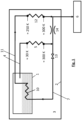
- Fig.1 shows a cryogenic tank with a removal device according to the state of the art.
- the cryogenic tank comprises an inner tank 1 for holding a medium, in particular hydrogen, an outer container 2 surrounding the inner tank 1, and an isolation space 3, namely a vacuum space, between the inner tank 1 and the outer container 2.
- a medium in particular hydrogen
- an outer container 2 surrounding the inner tank 1
- an isolation space 3 namely a vacuum space, between the inner tank 1 and the outer container 2.
- liquid hydrogen in the lower area, near the bottom of the inner tank 1 (shown in dashed lines), and gaseous hydrogen above it.
- the cryogenic tank comprises a removal device for the medium stored in the cryogenic tank.
- the removal device comprises a removal line 4, wherein the medium is guided through the removal line 4 from the inner tank 1 to a first heat exchanger 5 arranged outside the inner tank 1, namely in the insulation space 3. After the first heat exchanger 5, a partial removal flow is guided to a consumer 6.
- a recirculation partial flow is guided via a recirculation line 7 back into the inner tank 1 and can heat the stored medium there via an inner tank heat exchanger 10.
- the medium in the recirculation line 7 is then guided via a secondary section 11 of the recirculation line 7 out of the inner tank 1 into the insulation space 3, where it is heated by a second heat exchanger 12 and guided to the consumer 6.
- a valve 13 is arranged in the recirculation line 7 and between the branch of the recirculation line 7 from the extraction line 4 and the secondary section 11 of the recirculation line 7 a throttle 14.
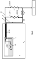
- the cryotank according to the invention Fig.2 differs from the cryotank of the Fig.1 in that the first heat exchanger 5 and the second heat exchanger 12 are arranged outside the outer container 2.
- the extraction line 4, the recirculation line 7 and the secondary section 11 of the recirculation line 7 are designed in the insulation space 3 in such a way that there is good thermal contact 8 between the extraction line 4, the recirculation line 7 and the secondary section 11 of the recirculation line 7.
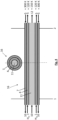
- the extraction line 4, the recirculation line 7 and the secondary section 11 of the recirculation line 7 form a common pipe arrangement 16 in the insulation space 3, which is formed by the formation of the extraction line 4, the recirculation line 7 and the secondary section 11 of the recirculation line 7 as coaxial pipes (see Fig.4 and 5 ).
- Cryogenic pressure gas for example hydrogen at approx. 30 K
- Cryogenic pressure gas can be removed from the cryogenic tank via extraction line 4 and heated using the first heat exchanger 5.
- a first partial gas flow is then recycled through a closed pipe system into the inner tank 1 to the inner tank heat exchanger 10 of the cryogenic tank.
- the inner tank heat exchanger 10 serves to evaporate and thus remove the cryogenic gas.
- a throttle 14 is used in the non-recycled second partial gas flow.
- the Fig.2 The valve 13 shown serves to switch off the recycled first partial gas flow.
- the recycling of the gas leads to its cooling, which is compensated by the second heat exchanger 12. After they are combined, both partial gas flows are fed to the consumer 6.
- the partial recycling enables heat to be fed into the cryogenic tank and thus a pressure build-up through evaporation of the cryogenic gas.
- the central component is the pipe arrangement designated "thermal contact" 8.
- This can firstly enable heat transfer between the cryogenic gas evaporated at approx. 30 K and the partial gas flow recirculated from the first heat exchanger 5 to the inner tank heat exchanger 10 and secondly enable heat transfer between the cryogenic gas evaporated at approx. 30 K and the partial gas flow recirculated from the inner tank heat exchanger 10 to the second heat exchanger 12.
- the former advantageously takes place in countercurrent and the latter in cocurrent (see Fig.4 and 5 ).
- the combination of valve 13 and throttle 14 can, as in Fig.3 shown, can be replaced by a control valve 15 to enable continuous control of the recirculated partial gas flow.
- a fluid guide according to Fig.5 In deviation from the fluid flow according to Fig.4 is a fluid guide according to Fig.5 possible, whereby the evaporated cryogenic gas flow (in the extraction line 4) must always be surrounded by the partial gas flow (radially inside and radially outside) leading to the inner tank heat exchanger 10 and coming from the inner tank heat exchanger 10.
- the performance of a fluid guide according to Fig.4 is higher than the Fig.5 .
- an accumulation of cryogenic fluid in the extraction line 4 can require an increased heat input through the coaxial pipe arrangement.
- the coaxial pipe arrangement 16 be larger in terms of heat transfer technology, in particular geometrically longer or longer.
- the pipe arrangement 16 can, for example, extend over at least 40%, preferably at least 60% or at least 70% of the length of the inner tank 1.
- a removal method for a cryogenic tank can comprise the steps of guiding the cryogenic gas flow removed from the inner tank 1 via a removal line 4, heating it in a first heat exchanger 5 and conveying a partial gas flow branched off from this back to the inner tank 1 via a recirculation line 7, and the partial gas flow directed to the inner tank 1 passing through an inner tank heat exchanger 10, then being guided via a line 11 to a second heat exchanger 12 and being combined with the main flow downstream of a control valve 15 throttling the main gas flow, wherein the evaporated cryogenic gas flow coming from the inner tank 1 and directed to the first heat exchanger 5 is in thermal contact with the partial gas flow fed to the inner tank 1 and discharged from it and heat transfer occurs between the three fluid flows.
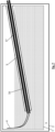
- the insulation vacuum i.e. the insulation space 3, around the coaxial tube arrangement 16, as in Fig.6 and 7 shown, into the installation space of the inner tank 1.
- This allows a length of the coaxial pipe arrangement 16 sufficient for heat transfer in conjunction with an easy-to-install multi-layer insulation (MLI) 17, as this is easier to apply to a straight pipe.
- MLI multi-layer insulation
- the coaxial arrangement of the three pipes also has advantages over the state of the art as shown in Fig.1 shown the advantage that only one pipeline instead of three needs to be provided with MLI, which reduces the manufacturing effort.
- Fig.6 This arrangement is illustrated, namely a coaxial pipe arrangement 16 with an insulation space 3, in particular vacuum, drawn into the inner tank 1 and multi-layer insulation 17.
- the pipe arrangement 16 can run essentially parallel to the bottom of the inner tank 1 and can preferably be located near the ceiling, i.e. at the top of the Inner tank 1, arranged as in Fig.6 To avoid fluid accumulation in the coaxial tube arrangement 16, it is also possible to position it at an angle, as shown in Fig.7 shown. In this case, the end of the extraction line 4 can preferably be moved upwards so that access to the extraction line 4 is nevertheless located near the ceiling, i.e. at the top of the inner tank 1, and gaseous medium can be extracted through the extraction line 4 during normal operation (cf. Fig. 7).
- Fig. 7 thus shows an inclined coaxial pipe arrangement 16 with vacuum drawn into the inner tank 1, i.e. insulation space 3, and MLI 17 around the pipe arrangement 16.
- both the inner tank heat exchanger 10 and the second heat exchanger 12 can be dispensed with.
- a fan 9 is used, which transports part of the cryogenic gas back into the inner tank 1 after it has been heated. There, it then gives off its heat to the liquid cryogenic gas and evaporates it. Before this, the warm cryogenic gas passes in countercurrent through the evaporated cold cryogenic gas that is escaping.
- a pipe arrangement 16 for such a thermal contact 8 according to Fig.8 is in Fig.9 and another possible version in Fig.10 shown.
- the “thermal contact” 8 is only achieved by a coaxial arrangement of two pipes.
- Fig.8 illustrates this.
- the design of the isolation vacuum 3 and the MLI 17 can be as in the Fig.6 and Fig.7 shown.
- Evaporated, gaseous hydrogen (H2) is fed via the extraction line 4 to the first heat exchanger 5 and from there recirculated further via the recirculation line 7 into the liquid hydrogen.
- the extraction line 4 can be radially within ( Fig.9 ) or radially outside ( Fig.10 ) of the recirculation line 7.
- a removal method for a cryogenic tank can then comprise the steps of guiding the cryogenic gas flow removed from the inner tank 1 via a removal line 4, heating it in a first heat exchanger 5 and conveying a partial gas flow branched off from this via a blower 9 and a recirculation line 7 back to the inner tank 1, wherein the gas flow coming from the inner tank 1 and the gas flow directed to the inner tank 1 are in thermal contact and heat is transferred between the two fluid flows.
- the invention thus shows that a good thermal contact 8 can be established between an evaporated cryogenic gas flow and a partial gas flow recirculated from a first heat exchanger 5 to the inner tank 1.
- the recirculated partial gas flow coming from the first heat exchanger 5 and flowing to the inner tank 1 can be mixed with the cold cryogenic gas in the latter.
- the heat transfer between the evaporated partial gas flow coming from the inner tank 1 and the recirculated partial gas flow leading to the inner tank 1 can be made possible by a coaxial arrangement of two pipes.
- the recirculated partial gas flow coming from the first heat exchanger 5 and flowing to the inner tank 1 can be guided via an inner tank heat exchanger 10 and then coming from the inner tank 1 to a second heat exchanger 12, and can be combined with the main flow downstream of a control valve 15 throttling the main gas flow, whereby a distinction is made between the evaporated cryogenic gas flow and the cryogenic gas flow from the inner tank heat exchanger 10 to the second There is good thermal contact with the partial gas stream recirculated in heat exchanger 12.
- the heat transfer between the vaporized cryogenic gas flow and the partial gas flow coming from the inner tank 1 and led to the inner tank 1 can be made possible by a coaxial arrangement of three tubes.
- the insulation vacuum around the coaxial tube arrangement 16 can be drawn into the area of the inner tank 1.
- the coaxial tube arrangement 16 can have an inclination relative to the horizontal.
- the coaxial tube arrangement 16 can be surrounded by super insulation.
- the cryogenic gas flow taken from the inner tank 1 can be guided via a line, heated in a first heat exchanger 5 and a partial gas flow branched off from this can be conveyed via a fan 9 and a line back to the inner tank 1, wherein the gas flow coming from the inner tank 1 and the gas flow conducted to the inner tank 1 are in thermal contact 8 and heat is transferred between the two fluid flows.
- the cryogenic gas flow taken from the inner tank 1 can be led through a line, heated in a first heat exchanger 5 and a partial gas flow branched off from this can be conveyed back to the inner tank 1 through a line and the partial gas flow led to the inner tank 1 can pass through an inner tank heat exchanger 10, then be led through a line to a second heat exchanger 12 and downstream of a control valve 15 throttling the main gas flow with the Main stream are combined, wherein the evaporated cryogenic gas stream coming from the inner tank 1 and conducted to the first heat exchanger 5 is in thermal contact 8 with the partial gas stream fed to the inner tank 1 and discharged from it and heat is transferred between the three fluid streams.
Landscapes
- Engineering & Computer Science (AREA)
- Mechanical Engineering (AREA)
- General Engineering & Computer Science (AREA)
- Filling Or Discharging Of Gas Storage Vessels (AREA)
Abstract
Description
- Die vorliegende Erfindung betrifft einen Kryotank, umfassend eine Entnahmevorrichtung für das im Kryotank gespeicherte Medium, insbesondere Wasserstoff.
- Kryotanks, die einen Innentank zur Aufnahme eines Mediums, insbesondere von Wasserstoff, umfassen, einen den Innentank umgebenden Außenbehälter, sowie einen Isolationsraum, insbesondere einen Vakuumraum, zwischen dem Innentank und dem Außenbehälter, sind bekannt. Solche Kryotanks können insbesondere als mobile Kryotanks in Kraftfahrzeugen verwendet werden, zur Mitnahme eines Mediums wie Wasserstoff oder LNG als Kraftstoff für den Antrieb des Kraftfahrzeuges.
- Solche Kryotanks umfassen üblicherweise eine Entnahmevorrichtung für das im Kryotank gespeicherte Medium, insbesondere Wasserstoff, so dass über eine Entnahmeleitung das Medium aus dem Innentank heraus zu einem außerhalb des Innentanks angeordneten ersten Wärmeübertrager geleitet wird, um den Wasserstoff zu erwärmen, wobei nach dem ersten Wärmeübertrager das erwärmte Medium einem Verbraucher zugeleitet wird.
- Es ist auch bereits bekannt, dass ein Rezirkulier-Teilstrom aus der Entnahmeleitung abgezweigt werden kann und über eine Rezirkulierleitung zurück in den Innentank geleitet werden kann, um das Medium im Tank zu erwärmen und den Druck im Innentank zu erhöhen.
- Dabei kann Kryodruckgas (z.B. Wasserstoff bei 30 K) dem Kryotank entnommen und mit Hilfe eines ersten Wärmeübertragers erwärmt werden. Anschließend wird ein erster Teilgasstrom durch ein geschlossenes Rohrleitungssystem in einen Innentankwärmeübertrager im Innentank des Kryotanks rezykliert. Der Innentankwärmeübertrager dient der Verdampfung und damit Entnahme des Kryogases. Die Rezyklierung des Gases führt zu dessen Abkühlung, was durch einen zweiten Wärmeübertrager kompensiert werden kann. Beide Gasströme werden nach deren Vereinigung dem Verbraucher zugeführt. Die teilweise Rezyklierung ermöglicht eine Wärmezufuhr in den Kryotank und damit einen Druckaufbau durch Verdampfung des kryogenen Gases.
- Eine derartige Entnahmevorrichtung erfordert eine Installation der Wärmeübertrager im Isolationsvakuum des Kyospeichers, da keine Bauteile deren Temperatur kleiner als 90 K ist, mit Luft in Kontakt kommen dürfen. Wäre dies der Fall, könnte es zu einer Luftsauerstoffkondensation kommen.
- Aufgrund des Wärmeübergangs durch Filmsieden im Innentankwärmeübertrager wird der rezyklierte Teilgasstrom üblicherweise nur geringfügig abgekühlt und damit seine Enthalpie nur in geringem Maße geändert. Dies ermöglicht zwar den zweiten Wärmeübertrager deutlich kleiner auszuführen, was allerdings zu Lasten des ersten Wärmeübertragers geht und damit dessen Einfriergefahr erhöht.
- Die bekannte Lösung hat demnach mindestens die folgenden Nachteile:
Die Wartung oder Reparatur der Wärmeübertrager wird erschwert oder unmöglich gemacht. Es besteht ein erhöhtes Potential von Undichtheiten im Isolationsvakuum. Komplizierte Leitungsführung im Vakuumraum führt zu schwieriger Applikation von Multi-Layer-Isolation (MLI) bzw. erhöhtem parasitären Wärmeeintrag in den Tank. Es besteht eine Gefahr des Einfrierens der Wärmeübertrager im Isolationsvakuum, insbesondere des ersten Wärmeübertragers, weil dieser üblicherweise mit 30 K kaltem Kryogas beaufschlagt wird. Es besteht die Notwendigkeit zwei stark verschiedene Wärmeübertrager zu verwenden. Es kommt zu einer Verkleinerung des Innentanks, weil Platz für die Wärmeübertrager und Rohrleitungen im Isolationsvakuum benötigt wird. - Es ist eine Aufgabe der Erfindung, einen Kryotank, umfassend eine Entnahmevorrichtung für das im Kryotank gespeicherte Medium, insbesondere Wasserstoff, anzugeben, der zumindest manche der genannten Nachteile nicht aufweist. Insbesondere soll ein Kryotank angegeben werden, der einen größeren Innentank und eine einfachere Wartung der Wärmeübertrager ermöglicht.
- Die Lösung der Aufgabe erfolgt durch einen Kryotank, umfassend eine Entnahmevorrichtung für das im Kryotank gespeicherte Medium, insbesondere Wasserstoff, wobei der Kryotank einen Innentank zur Aufnahme des Mediums umfasst, einen den Innentank umgebenden Außenbehälter, sowie einen Isolationsraum zwischen dem Innentank und dem Außenbehälter, wobei die Entnahmevorrichtung zumindest eine Entnahmeleitung umfasst, wobei durch die Entnahmeleitung das Medium aus dem Innentank heraus zu einem außerhalb des Innentanks angeordneten ersten Wärmeübertrager geleitet wird, wobei nach dem ersten Wärmeübertrager ein Entnahme-Teilstrom zu einem Verbraucher geleitet wird und ein Rezirkulier-Teilstrom über eine Rezirkulierleitung zurück in den Innentank geleitet wird, wobei der erste Wärmeübertrager außerhalb des Außenbehälters angeordnet ist, wobei die Entnahmeleitung und die Rezirkulierleitung im Isolationsraum so ausgebildet sind, dass ein guter thermischer Kontakt zwischen Entnahmeleitung und Rezirkulierleitung besteht.
- Erfindungsgemäß verfügt ein Kryotank über eine Entnahmeleitung, zur Entnahme des im Innentank gespeicherten Mediums, um das Medium einem Verbraucher zuzuführen. Von der Entnahmeleitung kann ein Teilstrom abgezweigt werden und in einer Rezirkulierleitung zurück in den Innentank geleitet werden, so dass der inzwischen erwärmte Teilstrom das Medium im Innentank erwärmen kann.
- Erfindungsgemäß wird der Kryotank so realisiert, dass der Wärmeübertrager, oder gegebenenfalls sogar mehrere, insbesondere zwei Wärmeübertrager, die der Erwärmung des entnommenen Mediums dienen, im Luftbereich, außerhalb des Außenbehälters und somit außerhalb des Isolationsraums angeordnet werden. Das ist dann technisch sinnvoll möglich, wenn die an den Wärmeübertragern auftretenden Temperaturen oberhalb der Verflüssigungstemperatur von Sauerstoff, das heißt größer als 90 K sind. Um sicher oberhalb dieser Temperatur zu liegen, sollten die Bauteiltemperaturen sogar nicht unter 120 K fallen.
- Die Entnahmevorrichtung des erfindungsgemäßen Kryotanks ist daher so ausgebildet, dass das Enthalpieangebot des rezirkulierten Teilgassstroms deutlich stärker ausgenutzt wird. Die Entnahmeleitung und die Rezirkulierleitung sind dafür im Isolationsraum so ausgebildet, dass ein guter thermischer Kontakt zwischen Entnahmeleitung und Rezirkulierleitung besteht. Das Medium in der Rezirkulierleitung kann somit Wärme an das Medium in der Entnahmeleitung abgeben.
- Weiterbildungen der Erfindung sind in den abhängigen Ansprüchen, der Beschreibung sowie den beigefügten Zeichnungen angegeben.
- Vorzugsweise sind die Entnahmeleitung und die Rezirkulierleitung im Isolationsraum als thermisch gut miteinander verbundene Rohre ausgebildet. Das Rohr, das die Entnahmeleitung bildet und das Rohr, das die Rezirkulierleitung bildet, können einander berührend angeordnet sein. Bevorzugt weisen die Entnahmeleitung und die Rezirkulierleitung aber zumindest abschnittsweise entlang ihrer Erstreckung durch den Isolationsraum und zumindest entlang eines Sektors ihres Umfangs einen der Entnahmeleitung und der Rezirkulierleitung gemeinsamen Rohrwandabschnitt auf. Die Entnahmeleitung und die Rezirkulierleitung teilen sich somit bevorzugt zumindest einen Teil einer Rohrwandung.
- Bevorzugt sind die Entnahmeleitung und die Rezirkulierleitung im Isolationsraum dadurch als thermisch gut miteinander verbundene Rohre ausgebildet, dass die Entnahmeleitung und die Rezirkulierleitung zumindest abschnittsweise entlang ihrer Erstreckung durch den Isolationsraum koaxiale Rohre bilden. Eines der beiden Rohre verläuft somit koaxial außerhalb des anderen Rohres. Vorzugsweise ist die Entnahmeleitung außen geführt und die Rezirkulierleitung innen geführt.
- In einer Ausführungsform wird der Rezirkulier-Teilstrom mittels eines Gebläses über die Rezirkulierleitung zurück in den Innentank befördert, und mündet vorzugsweise in Bodennähe in den Innentank, wo sich üblicherweise im Betrieb flüssiges Medium im Innentank befindet, so dass das flüssige kryogene Medium erwärmt wird und verdampft.
- Vorzugsweise wird der Rezirkulier-Teilstrom, der über die Rezirkulierleitung zurück in den Innentank geleitet wird, im Innentank durch einen Innentank-Wärmeübertrager geleitet und wird nach dem Innentank-Wärmeübertrager über einen Sekundärabschnitt der Rezirkulierleitung zu einem außerhalb des Innentanks angeordneten zweiten Wärmeübertrager geleitet. Das rezirkulierte Medium gibt somit seine Wärme über einen Innentank-Wärmeübertrager ab, der vorzugsweise in Bodennähe des Innentanks angeordnet ist und die Wärme im üblichen Betrieb an flüssiges Medium abgibt, und strömt dann weiter, wieder aus dem Innentank heraus, über einen Sekundärabschnitt der Rezirkulierleitung.
- Der wieder austretende Teilstrom des Mediums wird in einem zweiten Wärmeübertrager erneut erwärmt und kann dann einem Verbraucher zugeführt werden.
- Der zweite Wärmeübertrager ist bevorzugt ebenfalls außerhalb des Außenbehälters angeordnet.
- Die Entnahmeleitung und der Sekundärabschnitt der Rezirkulierleitung sind im Isolationsraum bevorzugt so ausgebildet, dass ein guter thermischer Kontakt zwischen Entnahmeleitung und Sekundärabschnitt der Rezirkulierleitung besteht. Somit kann ein Wärmeübertrag sowohl vom "primären" Teil der Rezirkulierleitung, als auch vom Sekundärabschnitt der Rezirkulierleitung zur Entnahmeleitung hin erfolgen.
- Die Entnahmeleitung und die Rezirkulierleitung und der Sekundärabschnitt der Rezirkulierleitung sind bevorzugt im Isolationsraum als thermisch gut miteinander verbundene Rohre ausgebildet, besonders bevorzugt dadurch, dass die Entnahmeleitung und die Rezirkulierleitung und der Sekundärabschnitt der Rezirkulierleitung zumindest abschnittsweise entlang ihrer Erstreckung zumindest einen Teil einer Rohrwandung jeweils miteinander, oder alle drei Rohre gemeinsam, teilen, und vorzugsweise alle drei Rohre koaxiale Rohre im Isolationsraum bilden.
- Die Entnahmeleitung ist dann bevorzugt das zwischen Rezirkulierleitung und Sekundärabschnitt der Rezirkulierleitung eingebettete, mittige Rohr. Die Rezirkulierleitung ist besonders bevorzugt das radial innen liegende, zentrale Rohr.
- Die thermisch gut miteinander verbundenen Leitungen, insbesondere Rohre, also die Rohranordnung aus zwei und bevorzugt aus drei Rohren, ist vorzugsweise zumindest teilweise und bevorzugt großteils in einem länglichen, sich in den Innentank hinein erstreckenden Bauraum angeordnet, der topologisch zum Isolationsraum gehört. Um die Rohranordnung ist bevorzugt eine Multi-Layer-Isolation (MLI) angeordnet.
- Die Erfindung wird im Folgenden beispielhaft unter Bezugnahme auf die Zeichnungen beschrieben.
- Fig. 1
- ist eine schematische Darstellung eines nicht erfindungsgemäßen Kryotanks.
- Fig. 2
- ist eine schematische Darstellung eines erfindungsgemäßen Kryotanks.
- Fig. 3
- ist eine schematische Darstellung eines weiteren erfindungsgemäßen Kryotanks.
- Fig. 4
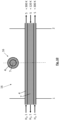
- ist eine schematische Darstellung einer Rohranordnung im Isolationsraum eines erfindungsgemäßen Kryotanks, von der Seite (großes Bild) und im Querschnitt von vorne (kleines Bild).
- Fig. 5
- ist eine schematische Darstellung einer weiteren Rohranordnung im Isolationsraum eines erfindungsgemäßen Kryotanks, von der Seite (großes Bild) und im Querschnitt von vorne (kleines Bild).
- Fig. 6
- ist eine schematische Darstellung einer Anordnung einer Rohranordnung im Isolationsraum eines erfindungsgemäßen Kryotanks.
- Fig. 7
- ist eine schematische Darstellung einer weiteren Anordnung einer Rohranordnung im Isolationsraum eines erfindungsgemäßen Kryotanks.
- Fig. 8
- ist eine schematische Darstellung eines weiteren erfindungsgemäßen Kryotanks.
- Fig. 9
- ist eine schematische Darstellung einer weiteren Rohranordnung im Isolationsraum eines erfindungsgemäßen Kryotanks, von der Seite (großes Bild) und im Querschnitt von vorne (kleines Bild).
- Fig. 10
- ist eine schematische Darstellung einer weiteren Rohranordnung im Isolationsraum eines erfindungsgemäßen Kryotanks, von der Seite (großes Bild) und im Querschnitt von vorne (kleines Bild).
-
Fig. 1 zeigt einen Kryotank mit einer Entnahmevorrichtung nach dem Stand der Technik. - Der Kryotank umfasst einen Innentank 1 zur Aufnahme eines Mediums, insbesondere Wasserstoff, einen den Innentank 1 umgebenden Außenbehälter 2, sowie einen Isolationsraum 3, nämlich einen Vakuumraum, zwischen dem Innentank 1 und dem Außenbehälter 2. Im Innentank 1 befindet sich im üblichen Betrieb des Kryotanks flüssiger Wasserstoff im unteren Bereich, in Bodennähe des Innentanks 1 (strichliert eingezeichnet) und darüber gasförmiger Wasserstoff.
- Der Kryotank umfasst eine Entnahmevorrichtung für das im Kryotank gespeicherte Medium. Die Entnahmevorrichtung umfasst eine Entnahmeleitung 4, wobei durch die Entnahmeleitung 4 das Medium aus dem Innentank 1 heraus zu einem außerhalb des Innentanks 1 angeordneten, nämlich im Isolationsraum 3 angeordneten, ersten Wärmeübertrager 5 geleitet wird. Nach dem ersten Wärmeübertrager 5 wird ein Entnahme-Teilstrom zu einem Verbraucher 6 geleitet. Ein Rezirkulier-Teilstrom wird über eine Rezirkulierleitung 7 zurück in den Innentank 1 geleitet und kann dort über einen Innentank-Wärmeübertrager 10 das gespeicherte Medium erwärmen. Danach wird das in der Rezirkulierleitung 7 befindliche Medium über einen Sekundärabschnitt 11 der Rezirkulierleitung 7 wieder aus dem Innentank 1 heraus in den Isolationsraum 3 geleitet, dort von einem zweiten Wärmeübertrager 12 erwärmt und an den Verbraucher 6 geleitet. Um einen gewünschten Teilstrom für die Rezirkulierung über die Rezirkulierleitung 7 abzweigen zu können, ist in der Rezirkulierleitung 7 ein Ventil 13 angeordnet und zwischen der Abzweigung der Rezirkulierleitung 7 von der Entnahmeleitung 4 und dem Sekundärabschnitt 11 der Rezirkulierleitung 7 eine Drossel 14.
- Der erfindungsgemäße Kryotank nach
Fig. 2 unterscheidet sich von dem Kryotank derFig. 1 dadurch, dass der erste Wärmeübertrager 5 und der zweite Wärmeübertrager 12 außerhalb des Außenbehälters 2 angeordnet sind. Die Entnahmeleitung 4, die Rezirkulierleitung 7 und der Sekundärabschnitt 11 der Rezirkulierleitung 7 sind im Isolationsraum 3 so ausgebildet, dass ein guter thermischer Kontakt 8 zwischen Entnahmeleitung 4, Rezirkulierleitung 7 und Sekundärabschnitt 11 der Rezirkulierleitung 7 besteht. Die Entnahmeleitung 4, die Rezirkulierleitung 7 und der Sekundärabschnitt 11 der Rezirkulierleitung 7 bilden im Isolationsraum 3 eine gemeinsame Rohranordnung 16 aus, die durch die Ausbildung von Entnahmeleitung 4, Rezirkulierleitung 7 und Sekundärabschnitt 11 der Rezirkulierleitung 7 als koaxiale Rohre gebildet wird (sieheFig. 4 und5 ). - Kryodruckgas, beispielsweise Wasserstoff bei ca. 30 K, kann dem Kryotank mittels Entnahmeleitung 4 entnommen und mit Hilfe des ersten Wärmeübertragers 5 erwärmt werden. Anschließend wird ein erster Teilgasstrom durch ein geschlossenes Rohrleitungssystem in den Innentank 1 zum Innentank-Wärmeübertrager 10 des Kryotanks rezykliert. Der Innentank-Wärmeübertrager 10 dient der Verdampfung und damit Entnahme des Kryogases. Um die Rezyklierung zu ermöglichen, wird eine Drossel 14 im nicht-rezyklierten zweiten Teilgasstrom verwendet. Das in
Fig. 2 eingezeichnete Ventil 13 dient zum Abschalten des rezyklierten ersten Teilgasstroms. Die Rezyklierung des Gases führt zu dessen Abkühlung, was durch den zweiten Wärmeübertrager 12 kompensiert wird. Beide Teilgasströme werden nach deren Vereinigung dem Verbraucher 6 zugeführt. Die teilweise Rezyklierung ermöglicht eine Wärmezufuhr in den Kryotank und damit einen Druckaufbau durch Verdampfung des kryogenen Gases. - Zentrales Bauteil ist die mit "Thermischen Kontakt" 8 bezeichnete Rohranordnung. Diese kann erstens eine Wärmeübertragung zwischen dem bei ca. 30 K verdampften Kryogas und dem vom ersten Wärmeübertrager 5 zum Innentank-Wärmeübertrager 10 rezirkulierten Teilgasstrom und zweitens eine Wärmeübertragung zwischen dem bei ca. 30 K verdampften Kryogas und dem vom Innentank-Wärmeübertrager 10 zum zweiten Wärmeübertrager 12 rezirkulierten Teilgasstrom ermöglichen. Vorteilhafterweise erfolgt ersteres dabei im Gegenstrom und zweiteres im Gleichstrom (siehe
Fig. 4 und5 ). Die Kombination von Ventil 13 und Drossel 14 kann, wie inFig. 3 dargestellt, durch ein Stellventil 15 ersetzt werden, um eine kontinuierliche Regelung des rezirkulierten Teilgasstroms zu ermöglichen. - Die Ausführung des in
Fig. 2 und3 mit "Thermischer Kontakt" 8 bezeichneten Bauteils, also der Rohranordnung 16 (sieheFig. 4 und5 ), erfolgt in einer besonders vorteilhaften Ausführung der erfindungsgemäßen Entnahmevorrichtung durch eine koaxiale Anordnung von drei Rohren. InFig. 4 undFig. 5 sind zwei mögliche Ausführungsformen dafür dargestellt, nämlich zwei verschiedene Fluidführungen in koaxialen Rohranordnungen 16. - Es hat sich gezeigt, dass durch die Anordnung nach
Fig. 2 undFig. 3 mit einer Rohranordnung 16 nachFig. 4 eine Erwärmung des bei ca. 30 K entnommenen Kryogasstroms (Wasserstoff) auf mindestens 120 K möglich wird, bevor dieser den ersten Wärmeübertrager 5 betritt. Der in den zweiten Wärmeübertrager 12 eintretende rezyklierte Teilgasstrom besitzt dann nur noch eine Temperatur von ca. 150 K. Seine Enthalpie ist somit deutlich besser ausgenutzt als bei der Anordnung nach Stand der Technik (vgl. die Angaben der Temperaturen inFig. 1 - im Vergleich auch zuFig. 2 undFig. 3 ). Eine Installation zweier gleichgroßer Wärmeübertrager 5 und 12 im Luftraum, also außerhalb des Isolationsraums 3, ist somit ohne die Gefahr einer Sauerstoffkondensation möglich. - In Abweichung zur Fluidführung nach
Fig. 4 ist eine Fluidführung nachFig. 5 möglich, wobei der verdampfte Kryogasstrom (in der Entnahmeleitung 4) immer von dem zum Innentank- Wärmeübertrager 10 führenden und vom Innentank- Wärmeübertrager 10 kommenden Teilgasstrom (radial innen und radial außen) umschlossen sein muss. Die Performance einer Fluidführung nachFig. 4 ist höher als die nachFig. 5 . - Bei der erfindungsgemäßen Entnahmevorrichtung ist darauf zu achten, dass bei einer Kryogasentnahme stets ein ausreichender Teilgasstrom rezirkuliert wird, um durch den Wärmeübergang die Austrittstemperatur des aus dem Vakuumbereich, also Isolationsraum 3, austretenden Kryogases oberhalb der Kondensationstemperatur von Sauerstoff zu halten. Dies ist bei einer Entnahme bei bereits erhöhtem Innentankdruck zu beachten, da in diesem Fall eine Kryogasverdampfung nicht sofort notwendig ist. Es spricht jedoch nichts gegen eine Kryogasrezirkulation mit geringerem Massenstrom, als für eine die Entnahme ausreichende Verdampfung notwendig wäre, um die Austrittstemperatur des entnommenen Kryogases mindestens oberhalb von 90 K zu halten. Der Druckabbau im Innentank 1 geht dann etwas langsamer vor sich, als bei einer Entnahme ohne Rezirkulation. Weiterhin kann eine Kryoflüssigkeitsansammlung in der Entnahmeleitung 4 einen erhöhten Wärmeeintrag durch die koaxiale Rohranordnung erfordern. Aus den beiden genannten Gründen empfiehlt es sich die koaxiale Rohranordnung 16 wärmeübergangstechnisch größer, insbesondere geometrisch länger bzw. lang zu dimensionieren. Die Rohranordnung 16 kann sich beispielsweise über mindestens 40%, bevorzugt mindestens 60 % oder mindestens 70 % der Länge des Innentanks 1 erstrecken.
- Ein Entnahmeverfahren für einen Kryotank kann die Schritte umfassen, dass der aus dem Innentank 1 entnommene Kryogasstrom über eine Entnahmeleitung 4 geführt, in einem ersten Wärmeübertrager 5 erwärmt und ein von diesem abgezweigter Teilgasstrom über eine Rezirkulierleitung 7 zurück zum Innentank 1 befördert wird, sowie der zum Innentank 1 geleitete Teilgasstrom einen Innentankwärmeübertrager 10 passiert, anschließend über eine Leitung 11 zu einem zweiten Wärmeübertrager 12 geführt und stromab eines den Hauptgasstrom androsselden Stellventils 15 mit dem Hauptstrom vereinigt wird, wobei der verdampfte, vom Innentank 1 kommende und zum ersten Wärmeübertrager 5 geleitete Kryogasstrom mit dem zum Innentank 1 zugeführten sowie von diesem abgeführten Teilgasstrom in einem thermischen Kontakt steht und es zu einer Wärmeübertragung zwischen den drei Fluidströmen kommt.
- In einer weiteren vorteilhaften Ausführung der erfindungsgemäßen Vorrichtung wird das Isolationsvakuum, also der Isolationsraum 3, um die koaxiale Rohranordnung 16, wie in
Fig. 6 und7 dargestellt, in den Bauraum des Innentanks 1 hineingezogen. Das ermöglicht eine für die Wärmeübertragung ausreichende Länge der koaxialen Rohranordnung 16 in Verbindung mit einer einfach zu installierenden Multi-Layer-Insulation (MLI) 17, da diese auf einem geraden Rohr einfacher zu applizieren ist. Die koaxiale Anordnung der drei Rohre hat zudem gegenüber dem Stand der Technik wie inFig. 1 dargestellt den Vorteil, dass nur eine Rohrleitung anstatt drei mit MLI versehen werden muss, was den Fertigungsaufwand verringert. InFig. 6 ist diese Anordnung verdeutlicht, nämlich eine koaxiale Rohranordnung 16 mit in den Innentank 1 hineingezogenem Isolationsraum 3, insbesondere Vakuum, und Multi-Layer-Insulation 17. - Die Rohranordnung 16 kann im Wesentlichen parallel zum Boden des Innentanks 1 verlaufen und kann bevorzugt nahe der Decke, also oben im Innentank 1, angeordnet sein, wie in
Fig. 6 dargestellt. Zur Vermeidung einer Flüssigkeitsansammlung in der koaxialen Rohranordnung 16 ist auch deren Schrägstellung möglich, wie inFig. 7 dargestellt. Hierbei kann vorzugsweise das Ende der Entnahmeleitung 4 nach oben verlegt werden, so dass der Zugang zur Entnahmeleitung 4 dennoch nahe der Decke, also oben im Innentank 1, angeordnet ist und im Normalbetrieb gasförmiges Medium durch die Entnahmeleitung 4 entnommen werden kann (vgl.Fig. 7). Fig. 7 zeigt somit eine schräg gestellte koaxiale Rohranordnung 16 mit in den Innentank 1 hineingezogenem Vakuum, also Isolationsraum 3, und MLI 17 um die Rohranordnung 16. - In einer weiteren vorteilhaften Ausführung eines erfindungsgemäßen Kryotanks kann sowohl auf den Innentank-Wärmeübertrager 10 als auch auf den zweiten Wärmeübertrager 12 verzichtet werden. In diesem Fall wird ein Gebläse 9 verwendet, welches einen Teil des Kryogases nach dessen Erwärmung zurück in den Innentank 1 befördert. Dort gibt es dann seine Wärme an das flüssige Kryogas ab und verdampft dieses. Zuvor passiert das warme Kryogas im Gegenstrom das verdampfte austretende kalte Kryogas. Eine Rohranordnung 16 für einen solchen thermischen Kontakt 8 gemäß
Fig. 8 ist inFig. 9 und eine weitere mögliche Ausführung inFig. 10 dargestellt. - Bei diesem "Offenen System" erfolgt der "Thermische Kontakt" 8 lediglich durch eine koaxiale Anordnung zweier Rohrleitungen.
Fig. 8 verdeutlicht dies. Die Gestaltung des Isolationsvakuums 3 und der MLI 17 kann wie in denFig. 6 undFig. 7 gezeigt erfolgen. Verdampfter, gasförmiger Wasserstoff (H2) wird über die Entnahmeleitung 4 zum ersten Wärmeübertrager 5 geleitet und von diesem weiter über die Rezirkulierleitung 7 in den flüssigen Wasserstoff rezirkuliert. Dabei kann die Entnahmeleitung 4 radial innerhalb (Fig. 9 ) oder radial außerhalb (Fig. 10 ) der Rezirkulierleitung 7 angeordnet sein. - Ein Entnahmeverfahren für einen Kryotank kann dann die Schritte umfassen, dass der aus dem Innentank 1 entnommene Kryogasstrom über eine Entnahmeleitung 4 geführt, in einem ersten Wärmeübertrager 5 erwärmt und ein von diesem abgezweigter Teilgasstrom über ein Gebläse 9 und eine Rezirkulierleitung 7 zurück zum Innentank 1 befördert wird, wobei der vom Innentank 1 kommende und der zum Innentank 1 geleitete Gasstrom in einem thermischen Kontakt stehen und es zu einer Wärmeübertragung zwischen beiden Fluidströmen kommt.
- Insgesamt zeigt somit die Erfindung, dass zwischen einem verdampften Kryogasstrom und einem von einem ersten Wärmeübertrager 5 zum Innentank 1 rezirkulierten Teilgasstrom ein guter thermischer Kontakt 8 eingerichtet sein kann. Der rezirkulierte Teilgasstrom vom ersten Wärmeübertrager 5 kommend und zum Innentank 1 strömend kann in diesem mit dem kalten Kryogas gemischt werden. Die Wärmeübertragung zwischen verdampftem, vom Innentank 1 kommenden und rezirkuliertem, zum Innentank 1 führenden Teilgasstrom kann durch eine koaxiale Anordnung zweier Rohre ermöglicht werden.
- Der rezirkulierte Teilgasstrom vom ersten Wärmeübertrager 5 kommend und zum Innentank 1 strömend kann über einen Innentank-Wärmeübertrager 10 geführt und anschließend aus dem Innentank 1 kommend zu einem zweiten Wärmeübertrager 12 geführt werden, sowie stromab eines den Hauptgasstrom androsselden Stellventils 15 mit dem Hauptstrom vereinigt werden, wobei zwischen dem verdampften Kryogasstrom sowie dem vom Innentank-Wärmeübertrager 10 zum zweiten Wärmeübertrager 12 rezirkulierten Teilgasstrom ein guter thermischer Kontakt besteht.
- Die Wärmeübertragung zwischen verdampftem Kryogasstrom sowie dem vom Innentank 1 kommenden und zum Innentank 1 geführten Teilgasstrom kann durch eine koaxiale Anordnung dreier Rohre ermöglicht werden.
- Das Isolationsvakuum um die koaxiale Rohranordnung 16 herum kann in den Bereich des Innentanks 1 hineingezogen werden. Die koaxiale Rohranordnung 16 kann eine Neigung gegenüber der Horizontalen aufweisen.
- Die koaxiale Rohranordnung 16 kann von einer Superisolation umgeben sein.
- Der aus dem Innentank 1 entnommene Kryogasstrom kann über eine Leitung geführt, in einem ersten Wärmeübertrager 5 erwärmt werden und ein von diesem abgezweigter Teilgasstrom über ein Gebläse 9 und eine Leitung zurück zum Innentank 1 befördert werden, wobei der vom Innentank 1 kommende und der zum Innentank 1 geleitete Gasstrom in einem thermischen Kontakt 8 stehen und es zu einer Wärmeübertragung zwischen beiden Fluidströmen kommt.
- Der aus dem Innentank 1 entnommene Kryogasstrom kann über eine Leitung geführt, in einem ersten Wärmeübertrager 5 erwärmt und ein von diesem abgezweigter Teilgasstrom über eine Leitung zurück zum Innentank 1 befördert werden und der zum Innentank 1 geleitete Teilgasstrom kann einen Innentank-Wärmeübertrager 10 passieren, anschließend über eine Leitung zu einem zweiten Wärmeübertrager 12 geführt werden und stromab eines den Hauptgasstrom androsselden Stellventils 15 mit dem Hauptstrom vereinigt werden, wobei der verdampfte, vom Innentank 1 kommende und zum ersten Wärmeübertrager 5 geleitete Kryogasstrom mit dem zum Innentank 1 zugeführten sowie von diesem abgeführten Teilgasstrom in einem thermischen Kontakt 8 steht und es zu einer Wärmeübertragung zwischen den drei Fluidströmen kommt.
-
- 1
- Innentank
- 2
- Außenbehälter
- 3
- Isolationsraum
- 4
- Entnahmeleitung
- 5
- erster Wärmeübertrager
- 6
- Verbraucher
- 7
- Rezirkulierleitung
- 8
- Thermischer Kontakt
- 9
- Gebläse
- 10
- Innentank-Wärmeübertrager
- 11
- Sekundärabschnitt der Rezirkulierleitung
- 12
- zweiter Wärmeübertrager
- 13
- Ventil
- 14
- Drossel
- 15
- Stellventil
- 16
- Rohranordnung
- 17
- Multi-Layer-Insulation (MLI)
Claims (10)
- Kryotank, umfassend eine Entnahmevorrichtung für das im Kryotank gespeicherte Medium, insbesondere Wasserstoff, wobei der Kryotank einen Innentank (1) zur Aufnahme des Mediums umfasst, einen den Innentank (1) umgebenden Außenbehälter (2), sowie einen Isolationsraum (3) zwischen dem Innentank (1) und dem Außenbehälter (2), wobei die Entnahmevorrichtung zumindest eine Entnahmeleitung (4) umfasst, wobei durch die Entnahmeleitung (4) das Medium aus dem Innentank (1) heraus zu einem außerhalb des Innentanks (1) angeordneten ersten Wärmeübertrager (5) geleitet wird, wobei nach dem ersten Wärmeübertrager (5) ein Entnahme-Teilstrom zu einem Verbraucher (6) geleitet wird und ein Rezirkulier-Teilstrom über eine Rezirkulierleitung (7) zurück in den Innentank (1) geleitet wird,
dadurch gekennzeichnet, dass der erste Wärmeübertrager (5) außerhalb des Außenbehälters (2) angeordnet ist, wobei die Entnahmeleitung (4) und die Rezirkulierleitung (7) im Isolationsraum (3) so ausgebildet sind, dass ein guter thermischer Kontakt (8) zwischen Entnahmeleitung (4) und Rezirkulierleitung (7) besteht. - Kryotank nach Anspruch 1,
dadurch gekennzeichnet, dass die Entnahmeleitung (4) und die Rezirkulierleitung (7) im Isolationsraum (3) als thermisch gut miteinander verbundene Rohre ausgebildet sind, bevorzugt dadurch, dass die Entnahmeleitung (4) und die Rezirkulierleitung (7) zumindest abschnittsweise entlang ihrer Erstreckung durch den Isolationsraum (3) und zumindest entlang eines Sektors ihres Umfangs einen der Entnahmeleitung (4) und der Rezirkulierleitung (7) gemeinsamen Rohrwandabschnitt aufweisen. - Kryotank nach zumindest einem der vorhergehenden Ansprüche,
dadurch gekennzeichnet, dass die Entnahmeleitung (4) und die Rezirkulierleitung (7) im Isolationsraum (3) als thermisch gut miteinander verbundene Rohre ausgebildet sind, dadurch, dass die Entnahmeleitung (4) und die Rezirkulierleitung (7) zumindest abschnittsweise entlang ihrer Erstreckung durch den Isolationsraum (3) koaxiale Rohre bilden, wobei vorzugsweise die Entnahmeleitung (4) außen geführt ist und die Rezirkulierleitung (7) innen geführt ist. - Kryotank nach zumindest einem der vorhergehenden Ansprüche,
dadurch gekennzeichnet, dass der Rezirkulier-Teilstrom mittels eines Gebläses (9) über die Rezirkulierleitung (7) zurück in den Innentank (1) befördert wird, bevorzugt in Bodennähe, also üblicherweise in flüssiges Medium im Innentank (1). - Kryotank nach zumindest einem der Ansprüche 1 bis 3,
dadurch gekennzeichnet, dass der Rezirkulier-Teilstrom, der über die Rezirkulierleitung (7) zurück in den Innentank (1) geleitet wird, im Innentank (1) durch einen Innentank-Wärmeübertrager (10) geleitet wird und nach dem Innentank-Wärmeübertrager (10) über einen Sekundärabschnitt (11) der Rezirkulierleitung (7) zu einem außerhalb des Innentanks (1) angeordneten zweiten Wärmeübertrager (12) geleitet wird. - Kryotank nach Anspruch 5,
dadurch gekennzeichnet , dass der zweite Wärmeübertrager (12) außerhalb des Außenbehälters (2) angeordnet ist. - Kryotank nach zumindest einem der Ansprüche 5 bis 6,
dadurch gekennzeichnet , dass die Entnahmeleitung (4) und der Sekundärabschnitt (11) der Rezirkulierleitung (7) im Isolationsraum (3) so ausgebildet sind, dass ein guter thermischer Kontakt (8) zwischen Entnahmeleitung (4) und Sekundärabschnitt (11) der Rezirkulierleitung (7) besteht. - Kryotank nach zumindest einem der Ansprüche 5 bis 7,
dadurch gekennzeichnet , dass die Entnahmeleitung (4) und die Rezirkulierleitung (7) und der Sekundärabschnitt (11) der Rezirkulierleitung (7) im Isolationsraum (3) als thermisch gut miteinander verbundene Rohre ausgebildet sind, bevorzugt dadurch, dass die Entnahmeleitung (4) und die Rezirkulierleitung (7) und der Sekundärabschnitt (11) der Rezirkulierleitung (7) zumindest abschnittsweise entlang ihrer Erstreckung durch den Isolationsraum (3) koaxiale Rohre bilden. - Kryotank nach Anspruch 8,
dadurch gekennzeichnet , dass die Entnahmeleitung (4) das zwischen Rezirkulierleitung (7) und Sekundärabschnitt (11) der Rezirkulierleitung (4) eingebettete, mittige Rohr bildet. - Kryotank nach zumindest einem der vorhergehenden Ansprüche,
dadurch gekennzeichnet , dass die thermisch gut miteinander verbundenen Leitungen, insbesondere Rohre, zumindest teilweise, bevorzugt großteils, in einem länglichen, sich in den Innentank (1) hinein erstreckenden Bauraum angeordnet sind, der zum Isolationsraum (3) gehört, wobei bevorzugt die Leitungen und/oder der längliche Bauraum horizontal oder schräg angeordnet sind.
Applications Claiming Priority (1)
| Application Number | Priority Date | Filing Date | Title |
|---|---|---|---|
| DE102023200257.4A DE102023200257B3 (de) | 2023-01-13 | 2023-01-13 | Kryotank umfassend eine Entnahmevorrichtung |
Publications (2)
| Publication Number | Publication Date |
|---|---|
| EP4400761A1 true EP4400761A1 (de) | 2024-07-17 |
| EP4400761B1 EP4400761B1 (de) | 2026-02-25 |
Family
ID=88920747
Family Applications (1)
| Application Number | Title | Priority Date | Filing Date |
|---|---|---|---|
| EP23211267.2A Active EP4400761B1 (de) | 2023-01-13 | 2023-11-21 | Kryotank umfassend eine entnahmevorrichtung |
Country Status (3)
| Country | Link |
|---|---|
| US (1) | US20240240762A1 (de) |
| EP (1) | EP4400761B1 (de) |
| DE (1) | DE102023200257B3 (de) |
Citations (3)
| Publication number | Priority date | Publication date | Assignee | Title |
|---|---|---|---|---|
| EP2118557B1 (de) * | 2007-01-17 | 2010-06-02 | Magna Steyr Fahrzeugtechnik AG & Co. KG | Speicherbehälter für tiefkaltes flüssiggas mit einer entnahmevorrichtung |
| DE19645488C5 (de) * | 1996-11-05 | 2012-08-30 | Air Liquide Deutschland Gmbh | System und Verfahren zum Entnehmen von kaltem Gas aus einem Kryotank |
| US20210372570A1 (en) * | 2020-05-28 | 2021-12-02 | Magna Steyr Fahrzeugtechnik Ag & Co Kg | Cryogenic storage system |
Family Cites Families (8)
| Publication number | Priority date | Publication date | Assignee | Title |
|---|---|---|---|---|
| AT9291U1 (de) | 2005-07-08 | 2007-07-15 | Magna Steyr Fahrzeugtechnik Ag | Speicherbehälter für tiefkaltes flüssiggas mit einer entnahmevorrichtung |
| DE102007057978A1 (de) * | 2007-12-03 | 2009-06-04 | Bayerische Motoren Werke Aktiengesellschaft | Betriebsverfahren für einen Kryodruck-Tank |
| DE102015118830A1 (de) * | 2015-11-03 | 2017-05-04 | Brugg Rohr Ag Holding | Einrichtung zum Betanken von Kraftfahrzeugen mit verflüssigtem Gas |
| DE102017222926A1 (de) | 2017-12-15 | 2019-06-19 | Robert Bosch Gmbh | Kraftstofffördereinrichtung für eine Brennkraftmaschine |
| US12209710B2 (en) | 2020-06-09 | 2025-01-28 | Chart Inc. | Cryogenic fluid dispensing system with heat management |
| FR3121732A1 (fr) * | 2021-04-13 | 2022-10-14 | L'air Liquide, Societe Anonyme Pour L'etude Et L'exploitation Des Procedes Georges Claude | Dispositif de stockage et de fourniture de fluide et véhicule, véhicule et procédé comportant un tel dispositif |
| FR3121731B1 (fr) | 2021-04-13 | 2023-02-24 | Air Liquide | Dispositif de stockage et de fourniture de fluide et véhicule, véhicule et procédé comportant un tel dispositif |
| FR3132560B1 (fr) * | 2022-02-10 | 2024-01-19 | Air Liquide | Dispositif et procédé de stockage et de fourniture de fluide |
-
2023
- 2023-01-13 DE DE102023200257.4A patent/DE102023200257B3/de active Active
- 2023-11-21 EP EP23211267.2A patent/EP4400761B1/de active Active
-
2024
- 2024-01-12 US US18/411,377 patent/US20240240762A1/en active Pending
Patent Citations (3)
| Publication number | Priority date | Publication date | Assignee | Title |
|---|---|---|---|---|
| DE19645488C5 (de) * | 1996-11-05 | 2012-08-30 | Air Liquide Deutschland Gmbh | System und Verfahren zum Entnehmen von kaltem Gas aus einem Kryotank |
| EP2118557B1 (de) * | 2007-01-17 | 2010-06-02 | Magna Steyr Fahrzeugtechnik AG & Co. KG | Speicherbehälter für tiefkaltes flüssiggas mit einer entnahmevorrichtung |
| US20210372570A1 (en) * | 2020-05-28 | 2021-12-02 | Magna Steyr Fahrzeugtechnik Ag & Co Kg | Cryogenic storage system |
Also Published As
| Publication number | Publication date |
|---|---|
| DE102023200257B3 (de) | 2024-05-29 |
| US20240240762A1 (en) | 2024-07-18 |
| EP4400761B1 (de) | 2026-02-25 |
Similar Documents
| Publication | Publication Date | Title |
|---|---|---|
| EP0805303B1 (de) | Verfahren und Verdampfer zum Verdampfen eines tiefkalten flüssigen Mediums | |
| DE102020206689B3 (de) | Kryogen-Speichersystem | |
| DE2734358A1 (de) | Kaelteerzeugungs-vorrichtung | |
| EP3371506B1 (de) | Einrichtung zum betanken von kraftfahrzeugen mit verflüssigtem gas | |
| DE69211237T2 (de) | Vakuumbehälter mit einem gekühlten Element | |
| DE102018005807A1 (de) | Verflüssigung eines gasförmigen Mediums | |
| DE112019002073T5 (de) | Kühlsystem für Niedertemperaturlager | |
| EP0574811B1 (de) | Verfahren zum Kaltfahren eines Speicherbehälters | |
| EP4400761B1 (de) | Kryotank umfassend eine entnahmevorrichtung | |
| EP4155601A1 (de) | Kryogen-speichersystem | |
| WO2018019434A1 (de) | Verfahren und vorrichtung zum gefrieren von an einen schacht angrenzendem erdreich mittels eines verflüssigten gases | |
| EP1802910A1 (de) | Vorrichtung zur erzeugung von hochkomprimiertem gas | |
| EP3210890B1 (de) | Kühlung von treibstoff für ein triebwerk | |
| EP3708897A1 (de) | Gas-tank-system, verfahren zum betreiben des gas-tank-systems und zug mit gas-tank-system | |
| DE102006046931A1 (de) | Indirekt arbeitendes Kühlsystem für ein Kühlfahrzeug | |
| DE102005021154B4 (de) | Abtausystem für Verdampfer von Kälteanlagen und Wärmepumpen sowie ein Verfahren zum Betrieb hierzu | |
| DE112023000239T5 (de) | Wärmetauschkomponente und Wärmetauschverfahren für eine Hydriervorrichtung | |
| DE102017008211B4 (de) | Verfahren und Vorrichtung zum Befüllen eines mobilen Kältemitteltanks mit einem kryogenen Kältemittel | |
| DE19704361C1 (de) | Betankungseinrichtung für kryogene Kraftstoffe und Verfahren zum abgasfreien Betanken von Fahrzeugen jeder Art mit unterkühlter Flüssigkeit aus einer derartigen Betankungseinrichtung | |
| EP3244154B1 (de) | Einspritzung in rohre eines rohrbündelwärmetauschers | |
| DE102016013459A1 (de) | Verfahren zur Temperaturänderung eines Fluids mittels eines Rohrbündelwärmetauschers und Rohrbündelwärmetauscher | |
| EP4244525B1 (de) | System umfassend einen kryobehälter und einen thermischen siphon | |
| DE102007004192A1 (de) | Verfahren und Vorrichtung zum Temperieren eines Mediums | |
| DE202020104343U1 (de) | Wärmepumpsystem | |
| DE1954681C (de) | Leitungssystem fur elektrische Leistungsübertragung |
Legal Events
| Date | Code | Title | Description |
|---|---|---|---|
| PUAI | Public reference made under article 153(3) epc to a published international application that has entered the european phase |
Free format text: ORIGINAL CODE: 0009012 |
|
| STAA | Information on the status of an ep patent application or granted ep patent |
Free format text: STATUS: REQUEST FOR EXAMINATION WAS MADE |
|
| 17P | Request for examination filed |
Effective date: 20240424 |
|
| AK | Designated contracting states |
Kind code of ref document: A1 Designated state(s): AL AT BE BG CH CY CZ DE DK EE ES FI FR GB GR HR HU IE IS IT LI LT LU LV MC ME MK MT NL NO PL PT RO RS SE SI SK SM TR |
|
| GRAP | Despatch of communication of intention to grant a patent |
Free format text: ORIGINAL CODE: EPIDOSNIGR1 |
|
| STAA | Information on the status of an ep patent application or granted ep patent |
Free format text: STATUS: GRANT OF PATENT IS INTENDED |
|
| RIC1 | Information provided on ipc code assigned before grant |
Ipc: F17C 7/02 20060101AFI20251111BHEP |
|
| INTG | Intention to grant announced |
Effective date: 20251124 |
|
| GRAS | Grant fee paid |
Free format text: ORIGINAL CODE: EPIDOSNIGR3 |
|
| GRAA | (expected) grant |
Free format text: ORIGINAL CODE: 0009210 |
|
| STAA | Information on the status of an ep patent application or granted ep patent |
Free format text: STATUS: THE PATENT HAS BEEN GRANTED |
|
| AK | Designated contracting states |
Kind code of ref document: B1 Designated state(s): AL AT BE BG CH CY CZ DE DK EE ES FI FR GB GR HR HU IE IS IT LI LT LU LV MC ME MK MT NL NO PL PT RO RS SE SI SK SM TR |
|
| REG | Reference to a national code |
Ref country code: CH Ref legal event code: F10 Free format text: ST27 STATUS EVENT CODE: U-0-0-F10-F00 (AS PROVIDED BY THE NATIONAL OFFICE) Effective date: 20260225 Ref country code: GB Ref legal event code: FG4D Free format text: NOT ENGLISH |
|
| REG | Reference to a national code |
Ref country code: DE Ref legal event code: R096 Ref document number: 502023003152 Country of ref document: DE |
|
| REG | Reference to a national code |
Ref country code: IE Ref legal event code: FG4D Free format text: LANGUAGE OF EP DOCUMENT: GERMAN |