EP4400714A1 - Braking force measuring method - Google Patents
Braking force measuring method Download PDFInfo
- Publication number
- EP4400714A1 EP4400714A1 EP24151365.4A EP24151365A EP4400714A1 EP 4400714 A1 EP4400714 A1 EP 4400714A1 EP 24151365 A EP24151365 A EP 24151365A EP 4400714 A1 EP4400714 A1 EP 4400714A1
- Authority
- EP
- European Patent Office
- Prior art keywords
- nacelle
- ring gear
- jig
- input torque
- pinion
- Prior art date
- Legal status (The legal status is an assumption and is not a legal conclusion. Google has not performed a legal analysis and makes no representation as to the accuracy of the status listed.)
- Pending
Links
Images






Classifications
-
- F—MECHANICAL ENGINEERING; LIGHTING; HEATING; WEAPONS; BLASTING
- F03—MACHINES OR ENGINES FOR LIQUIDS; WIND, SPRING, OR WEIGHT MOTORS; PRODUCING MECHANICAL POWER OR A REACTIVE PROPULSIVE THRUST, NOT OTHERWISE PROVIDED FOR
- F03D—WIND MOTORS
- F03D17/00—Monitoring or testing of wind motors, e.g. diagnostics
-
- F—MECHANICAL ENGINEERING; LIGHTING; HEATING; WEAPONS; BLASTING
- F03—MACHINES OR ENGINES FOR LIQUIDS; WIND, SPRING, OR WEIGHT MOTORS; PRODUCING MECHANICAL POWER OR A REACTIVE PROPULSIVE THRUST, NOT OTHERWISE PROVIDED FOR
- F03D—WIND MOTORS
- F03D7/00—Controlling wind motors
- F03D7/02—Controlling wind motors the wind motors having rotation axis substantially parallel to the air flow entering the rotor
- F03D7/0204—Controlling wind motors the wind motors having rotation axis substantially parallel to the air flow entering the rotor for orientation in relation to wind direction
-
- F—MECHANICAL ENGINEERING; LIGHTING; HEATING; WEAPONS; BLASTING
- F03—MACHINES OR ENGINES FOR LIQUIDS; WIND, SPRING, OR WEIGHT MOTORS; PRODUCING MECHANICAL POWER OR A REACTIVE PROPULSIVE THRUST, NOT OTHERWISE PROVIDED FOR
- F03D—WIND MOTORS
- F03D7/00—Controlling wind motors
- F03D7/02—Controlling wind motors the wind motors having rotation axis substantially parallel to the air flow entering the rotor
- F03D7/0244—Controlling wind motors the wind motors having rotation axis substantially parallel to the air flow entering the rotor for braking
-
- F—MECHANICAL ENGINEERING; LIGHTING; HEATING; WEAPONS; BLASTING
- F05—INDEXING SCHEMES RELATING TO ENGINES OR PUMPS IN VARIOUS SUBCLASSES OF CLASSES F01-F04
- F05B—INDEXING SCHEME RELATING TO WIND, SPRING, WEIGHT, INERTIA OR LIKE MOTORS, TO MACHINES OR ENGINES FOR LIQUIDS COVERED BY SUBCLASSES F03B, F03D AND F03G
- F05B2260/00—Function
- F05B2260/90—Braking
- F05B2260/902—Braking using frictional mechanical forces
-
- F—MECHANICAL ENGINEERING; LIGHTING; HEATING; WEAPONS; BLASTING
- F05—INDEXING SCHEMES RELATING TO ENGINES OR PUMPS IN VARIOUS SUBCLASSES OF CLASSES F01-F04
- F05B—INDEXING SCHEME RELATING TO WIND, SPRING, WEIGHT, INERTIA OR LIKE MOTORS, TO MACHINES OR ENGINES FOR LIQUIDS COVERED BY SUBCLASSES F03B, F03D AND F03G
- F05B2260/00—Function
- F05B2260/90—Braking
- F05B2260/903—Braking using electrical or magnetic forces
-
- F—MECHANICAL ENGINEERING; LIGHTING; HEATING; WEAPONS; BLASTING
- F05—INDEXING SCHEMES RELATING TO ENGINES OR PUMPS IN VARIOUS SUBCLASSES OF CLASSES F01-F04
- F05B—INDEXING SCHEME RELATING TO WIND, SPRING, WEIGHT, INERTIA OR LIKE MOTORS, TO MACHINES OR ENGINES FOR LIQUIDS COVERED BY SUBCLASSES F03B, F03D AND F03G
- F05B2270/00—Control
- F05B2270/30—Control parameters, e.g. input parameters
- F05B2270/331—Mechanical loads
-
- Y—GENERAL TAGGING OF NEW TECHNOLOGICAL DEVELOPMENTS; GENERAL TAGGING OF CROSS-SECTIONAL TECHNOLOGIES SPANNING OVER SEVERAL SECTIONS OF THE IPC; TECHNICAL SUBJECTS COVERED BY FORMER USPC CROSS-REFERENCE ART COLLECTIONS [XRACs] AND DIGESTS
- Y02—TECHNOLOGIES OR APPLICATIONS FOR MITIGATION OR ADAPTATION AGAINST CLIMATE CHANGE
- Y02E—REDUCTION OF GREENHOUSE GAS [GHG] EMISSIONS, RELATED TO ENERGY GENERATION, TRANSMISSION OR DISTRIBUTION
- Y02E10/00—Energy generation through renewable energy sources
- Y02E10/70—Wind energy
- Y02E10/72—Wind turbines with rotation axis in wind direction
Definitions
- the present invention relates to a braking force measuring method.
- the wind turbine has a brake device that brakes its nacelle by pressing a friction body against a ring gear that holds a yaw unit (nacelle) of blades. Because the rotational force of the nacelle rotated by wind power is quite large, the braking force of the brake device also becomes large. It is difficult to directly measure the braking force of the brake device with, for example, a stress sensor. Conventionally, a wire is tied to the blade or hub while the ring gear is braked and the wire is then pulled with heavy machinery to make the nacelle turn. The actual braking force is measured as the external force at which the nacelle begins to turn.
- Patent Literature 1 Japanese Patent Application Publication No. 2015-140777
- the present invention is intended to overcome the above drawback, and one object is to provide a method of measuring braking force with which it is possible to safely and easily measure the braking force of the brake device.
- aspects of the present invention are configured as follows.
- the wind turbine including: a ring gear fixed to a tower of the wind turbine or a nacelle of the wind turbine; a yaw drive device driving a pinion that meshes with the ring gear to turn the wind turbine in a yaw direction, the yaw drive device being fixed to the other of the tower or the nacelle; and the brake device pressing a friction body against the ring gear to keep the nacelle from turning in the yaw direction.
- the method includes: a brake step of braking the ring gear by the brake device; a measurement step of measuring a load on a rotating shaft of the pinion that mesh with the braked ring gear; a determination step of determining a maximum value of the load during a time period when input torque is applied to the pinion, the input torque being applied with the nacelle held still, the input torque being applied until the friction body begins to slip and the nacelle begins to turn in the yaw direction; and a conversion step of converting the determined load to the braking force.
- the braking force of the brake device can be measured by applying input torque to the pinion until the friction body begins to slip and the nacelle that has been held still begins to turn in the yaw direction, determining the maximum value of the load during that time, and converting the determined load (maximum value) to the braking force.
- the braking force of the brake device can be measured without the need to directly pull the blades or hub with large heavy machinery. Therefore, the braking force of the brake device can be measured safely and easily.
- the braking force of the brake device can be measured safely and easily.
- Fig. 1 is a perspective view of a wind turbine according to the first embodiment.
- the wind turbine 1 includes a nacelle 10, a tower 20, blades 30, and a hub 40.
- an XYZ orthogonal coordinate system is used as required.
- the X and Y directions are mutually orthogonal in the horizontal plane.
- the Z direction is orthogonal to the X and Y directions (vertical direction).
- the following description is made with the arrows shown in the drawings indicating the X, Y and Z directions, and the head side and the tail side of each arrow indicate the positive (+) side and the negative (-) side, respectively.
- the upper side and the lower side in the vertical direction are respectively denoted as the +Z side and the -Z side.
- the nacelle 10 is mounted on the top end (the end in the +Z direction) of the tower 20.
- the blades 30 are mounted to the nacelle 10 via the hub 40.
- the nacelle 10 turns the blades 30 and hub 40 to adjust their orientation in the yaw direction.
- the tower 20 is installed on the land or on the sea, for example.
- the tower 20 extends upward in the vertical direction from the land or the sea.
- the blades 30 receive wind force and generate a rotational force.
- the number of blades 30 is three, but the embodiment is not limited.
- the number of the blades 30 can be changed depending on design specifications.
- the hub 40 is mounted to the nacelle 10. Three (can be any number more than one) blades 30 are mounted to the hub 40.
- the hub 40 is configured to transmit to a rotating shaft (not shown) the rotational force (motive power) generated by the blades 30 when acted upon by a force of wind.
- the hub 40 transmits the motive power generated by the wind force to the nacelle 10 via the rotating shaft.
- the hub 40 includes pitch drive mechanisms (not shown) for generating a pitch drive force for rotating the blades 30 in the pitch direction.
- Each blade 30 is provided with a pitch drive mechanism.
- the pitch drive mechanisms rotate the blades 30 in the pitch direction to control the angles of the blades 30 in accordance with the wind velocity.
- the motive power generated by the rotation of the blades 30 is transmitted from the hub 40 to a power generator (not shown) in the nacelle 10.
- the generator converts the motive power into electric power. In this way, the wind turbine 1 generates power from wind.
- Fig. 2 is a top view showing a relationship between the tower and the yaw drive device according to the first embodiment.
- Fig. 3 illustrates the yaw drive device according to the first embodiment.
- the wind turbine 1 includes a ring gear 22, a yaw drive device 100, and a brake device 54.
- the ring gear 22 is fixed to the tower 20.
- the ring gear 22 is positioned on the top portion of the tower 20.
- the ring gear 22 is disposed on an inner wall of the tower 20.
- the ring gear 22 is used to drive the turning of the nacelle 10 in the yaw direction.
- the ring gear 22 may be disposed on an outer wall of the tower 20.
- the yaw drive device 100 is fixed to the nacelle 10.
- the yaw drive device 100 drives a pinion 150 meshing with the ring gear 22 to rotate the wind turbine in the yaw direction.
- yaw drive devices 100-1, 100-2, 100-3, and 100-4 are mounted to the nacelle 10. These yaw drive devices 100-1, 100-2, 100-3, and 100-4 may be hereinafter collectively referred to simply as "the yaw drive devices 100."
- the yaw drive devices 100 are driven and rotated in the R direction in Fig. 2 by the motor drive force.
- the yaw drive devices 100 may also be able to be driven and rotated in the opposite direction to the R direction.
- a force such as a gust of wind applied to the nacelle 10, the tower 20 or the like generates a tangential force between the ring gear 22 and the pinion gears 150.
- the tangential force is generated in the tangential direction of the gear forming surface of the ring gear 22.
- the tangential force applies a torsional stress to a speed reducing unit 164 of each of the yaw drive devices 100.
- the tangential force applies a tensile stress and a compressive stress to a fastener in each of the yaw drive devices 100.
- the yaw drive device 100 includes a casing 110, a flange 120, bolts 130, an output shaft 140, and a pinion 150.
- the flange 120 is mounted to the casing 110.
- the flange 120 is connected to the nacelle 10 with the bolts 130.
- the bolt 130 is an example of fasteners used to secure the yaw drive device 100 to the nacelle 10.
- the fasteners are not limited to the bolts 130 but may be other known members.
- One end (+Z end) of the output shaft 140 is connected to the interior of the casing 110 and the flange 120.
- the other end (-Z end) of the output shaft 140 has the pinion gear 150 provided thereon.
- the output shaft 140 and pinion 150 are examples of transmission parts that transmit driving and braking forces from the yaw drive device 100 to the tower 20.
- the pinion 150 is positioned so as to mesh with the ring gear 22.
- the pinion 150 is rotated by the driving force outputted from the output shaft 140 to cause the yaw drive device 100 to revolve in the revolving direction (device movement direction).
- the yaw drive devices 100 in turn cause the nacelle 10 to turn in the yaw direction relative to the tower 20.
- the yaw drive device 100 includes a motor brake unit 160, a motor drive unit 162, and a speed reducing unit 164.
- the motor brake unit 160 generates a braking force for the output shaft 140.
- the motor brake unit 160 here applies the braking force directly to the output shaft 140. It is also possible that the braking force is applied indirectly to the output shaft 140. For example, the force of the motor brake unit 160 may be applied to a member other than the output shaft 140 and then applied to the output shaft 140 from this member.
- the motor brake unit 160 generates the braking force by an electromagnetic action in accordance with a control signal provided externally.
- the motor brake unit 160 is configured to generate a braking force while being fed with a voltage.
- the brake unit 160 is configured not to generate a braking force when no voltage is supplied thereto.
- the motor brake unit 160 may be, for example, an electromagnetic brake.
- the motor brake unit 160 generates a higher braking force as the supplied electric power is higher.
- the motor brake unit 160 may be configured to generate a braking force when no voltage is supplied thereto.
- the motor brake unit 160 may be an electromagnetic brake that applies brakes when no voltage is supplied thereto.
- the motor drive unit 162 generates a drive force for the output shaft 140.
- the motor drive unit 162 is configured to cause an electromagnetic force to generate a driving force in response to a control signal fed from outside.
- the speed reducing unit 164 reduces the rotation speed according to the drive force generated by the motor drive unit 162 to increase the drive torque.
- the function of the yaw drive device 100 is not limited to generating driving and braking forces.
- the yaw drive device 100 may generate a braking force by generating a drive force in an opposite direction to the direction of the drive force for rotating the nacelle 10. In such a case, the yaw drive device 100 does not need to include the motor brake unit 160.
- the yaw drive devices 100 each include bolt strain sensors 166a and 166b.
- the bolt strain sensors 166a and 166b are herein collectively referred to as "bolt strain sensors 166".
- the bolt strain sensors 166 are an example of an obtaining unit for obtaining information on the load.
- the bolt strain sensors 166 measure the strain on the bolts 130 used to attach the yaw drive device 100 to the nacelle 10.
- the strain sensors 166 each output a signal corresponding to the strain generated in the bolt 130.
- the strain generated in the fastening bolts 130 change in accordance with the tangential force.
- the brake device 54 presses a friction body 50 against the ring gear 22 to keep the nacelle 10 from turning in the yaw direction.
- the brake device 54 is a hydraulic brake for applying a braking force to the ring gear 22.
- the brake device 54 includes a caliper brake mechanism.
- the brake device 54 has a hydraulic braking unit 52 and the friction body 50.
- the hydraulic brake unit 52 moves the friction body 50 in the Z direction shown in Fig. 3 in accordance with a control signal provided externally.
- the hydraulic brake unit 52 applies a braking force to the ring gear 22 by urging the friction body 50 against the ring gear 22.
- the wind turbine 1 is preferably capable of adjusting the braking force applied to the ring gear 22.
- the brake device 54 is not limited to being a hydraulic brake. Alternatively, it may be a spring brake.
- the spring force (biasing force) of the spring brake may apply a braking force to the ring gear 22.
- the brake device 54 may include both a hydraulic brake and a spring brake.
- the configuration of the brake device can be modified in accordance with design specifications.
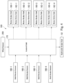
- Fig. 4 is a block diagram of the wind turbine according to the first embodiment.
- the yaw drive device 100 includes a control unit 170, bolt strain sensors 166-1, 166-2, 166-3, and 166-4, motor brake units 160-1, 160-2, 160-3, and 160-4, motor drive units 162-1, 162-2, 162-3, and 162-4, the hydraulic brake unit 52, and a wind sensor 200.
- the bolt strain sensors 166-1, 166-2, 166-3,and 166-4 may be hereinafter collectively referred to simply as “the bolt strain sensors 166”
- the motor brake units 160-1, 160-2, 160-3, and 160-4 may be hereinafter collectively referred to simply as “the brake units 160”
- the motor drive units 162-1, 162-2, 162-3, and 162-4 may be hereinafter collectively referred to simply as “the motor drive units 162".
- the bolt strain sensor 166-1 corresponds to the strain sensors 166a and 166b in the yaw drive device 100-1.
- the bolt strain sensor 166-2 corresponds to the strain sensors 166a and 166b in the yaw drive device 100-2.
- the bolt strain sensor 166-3 corresponds to the strain sensors 166a and 166b in the yaw drive device 100-3.
- the bolt strain sensor 166-4 corresponds to the strain sensors 166a and 166b in the yaw drive device 100-4.
- Each of the yaw drive devices 100 may include more than two bolt strain sensors 166.
- the motor brake unit 160-1 corresponds to the motor brake unit 160 in the yaw drive device 100-1.
- the motor brake unit 160-2 corresponds to the motor brake unit 160 in the yaw drive device 100-2.
- the motor brake unit 160-3 corresponds to the motor brake unit 160 in the yaw drive device 100-3.
- the motor brake unit 160-4 corresponds to the motor brake unit 160 in the yaw drive device 100-4.
- the motor drive unit 162-1 corresponds to the motor drive unit 162 in the yaw drive device 100-1.
- the motor drive unit 162-2 corresponds to the motor drive unit 162 in the yaw drive device 100-2.
- the motor drive unit 162-3 corresponds to the motor drive unit 162 in the yaw drive device 100-3.
- the motor drive unit 162-4 corresponds to the motor drive unit 162 in the yaw drive device 100-4.
- the wind sensor 200 is disposed, for example, on the top surface of the nacelle 10.
- the wind sensor 200 detects wind speed and direction.
- the wind sensor 200 senses the wind speed and the wind direction and outputs the sensing results to the control device 170.
- the wind sensor 200 may be constituted by a wind speed sensor and a wind direction sensor.
- the control unit 170 supervises four (an example of the plurality of)yaw drive devices 100.
- the control unit 170 is formed of, for example, a processor such as a CPU (Central Processing Unit) executing a program stored on a program memory.
- the control unit 170 may alternatively be formed of hardware such as an LSI (Large Scale Integration), an ASIC (Application Specific Integrated Circuit), or a FPGA (Field-Programmable Gate Array) or formed of software and hardware cooperating with each other.
- the control unit 170 receives a strain sensing signal from each of the strain sensors 166-1, 166-2, 166-3, and 166-4.
- the control unit 170 receives a wind sensing signal (results of detection of the wind speed and direction) from the wind sensor 200.
- the control unit 170 outputs control signals to the brake units 160-1, 160-2, 160-3, and 160-4, the motor drive units 162-1, 162-2, 162-3, and 162-4, and the hydraulic brake unit 52 based on the strain sensing signals and the wind sensing signal.
- FIG. 5 is a flowchart of the method of measuring a braking force according to the first embodiment.
- Fig. 6 shows perspective views of a jig and the yaw drive device according to the first embodiment.
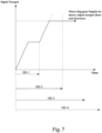
- Fig.7 illustrates a relationship between input torque and time. Referring to Figs.
- the method of measuring a braking force includes: a brake step (step S11) in which the brake device 54 brakes the ring gear 22; an attachment step (step S12) in which the jig 70 is attached to the rotating shaft of the pinion 150; a measurement step (step S13) of measuring the load on the rotating shaft of the pinion 150 that engages with the braked ring gear 22; a determination step (step S14) in which the nacelle 10 is first held still, an input torque is applied to the pinion 150 until the friction body 50 begins to slip and begins to turn in the yaw direction, and the maximum value of the load during a time period when the input torque is applied is determined; and a conversion step (step S15) in which the determined load is converted into the braking force.
- a braking force is applied to the ring gear 22 by pressing the friction body 50 against the ring gear 22. This causes the ring gear 22 to be braked.
- the process proceeds to the attachment step.
- the jig 70 used in the attachment step includes an input portion 72 to which input torque is supplied from an external power device 80 and a worm gear 74 that reduces and transmits the input torque.
- the input portion 72 and the worm gear 74 may be configured to form a single body together.
- the external power device 80 is an electric wrench, electric screwdriver, etc.
- the jig 70 includes a cylindrical flange 78, the input portion 72, the worm gear 74, and a torque meter 76.
- the worm gear 74 and torque meter 76 are provided inside the cylindrical flange 78.
- the torque meter 76 is mounted on a rotating shaft that connects the input portion 72 and the worm gear 74.
- the worm gear 74 is an example of a unidirectional rotation mechanism that permits rotation in one direction but limits rotation in the other direction.
- the unidirectional rotation mechanism is not limited to the worm gear 74, but may also be formed of a clutch (e.g., one-way clutch, electromagnetic clutch, etc.).
- the unidirectional rotation mechanism can be configured in various manners in accordance with design specifications.
- the worm gear 74 of the jig 70 may be connected to the rotating shaft of the pinion 150 by removing the case 110 (see Fig. 3 ) or other parts of the yaw drive device 100.
- the cylindrical flange 78 of the jig 70 may be connected to the flange 120 (see Fig. 3 ) of the yaw drive device 100 with the bolts 130 (see Fig. 3 ).
- the bolts 130 are an example of the attaching member that attaches the jig 70 to the rotating shaft of the pinion 150.
- the attaching member of the jig 70 is not limited to the bolts 130, but may be any other member.
- the jig 70 may be attached directly to the rotating shaft of the pinion 150 by removing a fan cover 101 (see Fig. 6 ).
- the jig 70 may be attached directly to the rotating shaft of the pinion 150 by removing a motor 102 (see Fig. 6 ).
- the method of attaching the jig 70 to the rotating shaft of the pinion 150 may be modified according to the design specifications.
- the wind turbine 1 has four (one example of the plurality) pinions 150 that mesh with the ring gear 22.
- the jig 70 is attached to each of the rotating shafts of the four (one example of the plurality) pinions 150. After the attachment step, the process proceeds to the measurement step.
- the value obtained by the torque meter 76 is used as the measured load.
- the load on the rotating shaft of the pinion 150 meshing with the braked ring gear 22 may be measured indirectly. After the measurement step, the process proceeds to the determination step.
- the nacelle 10 is first held still, input torque is applied to the pinion 150 from the external power device 80 until the friction body 50 begins to slip and the nacelle 10 begins to turn in the yaw direction, and the maximum value of the load (detected by the torque meter 76) during that time is determined.
- the nacelle 10 is first held still, a first input torque is inputted from the external power device 80 to the input portion 72 of the first jig 70 (e.g., the jig 70 attached to the yaw drive device 100-1) of the four (one example of the plurality) jigs 70.
- the second input torque is subsequently inputted from the external power device 80 to the input portion 72 of the second jig 70 (e.g., the jig 70 attached to the yaw drive device 100-3) located diagonally to the first jig on the circumference along the ring gear 22 among the plurality of the jigs 70.
- the nacelle 10 is first held still, and the first input torque is then inputted from the external power device 80 to the input portion 72 of the first jig 70 (e.g., the jig 70 attached to the yaw drive device 100-1) among the plurality of the jigs 70.
- the first input torque may be inputted such that it gradually increases to a first predetermined value (e.g., an upper limit of the first input torque).
- the nacelle 10 is first held still, and the second input torque is then inputted from the external power device 80 to the input portion 72 of the second jig 70 (e.g., the jig 70 attached to the yaw drive device 100-3 among the plurality of the jigs 70).
- the second input torque may be inputted such that it gradually increases to a second predetermined value (e.g., an upper limit of the second input torque).
- Fig. 7 shows the state in which the ring gear 22 against which the friction body 50 is pressed begins to move before the second input torque to the input portion 72 of the jig 70 attached to the yaw drive device 100-3 reaches the second predetermined value.
- the torque meter 76 is a static value. Strictly speaking, it rotates by an internal gap.
- the total input torque is 150.
- the above total input torque value is determined as the maximum value of the load (detected by the torque meter 76) during the time period from when the nacelle 10 is held and to when the friction body 50 begins to slip and the nacelle 10 begins to turn in the yaw direction. After the determination step, the conversion step is performed.
- the determined load (detected by the torque meter 76) is converted to a braking force.
- the input torque described above may be converted to an output torque, and the converted output torque may be considered as the braking force of the brake device 54.
- Tout is the output torque
- Tin is the input torque
- A is the reduction ratio of the jig 70
- B is the reduction ratio of the yaw drive device 100
- H is a coefficient.
- the reduction ratio A corresponds to the reduction ratio of the reduction mechanism (e.g., the mechanism including the worm gear 74, etc.) of the jig 70.
- the reduction ratio B corresponds to the reduction ratio of the reduction mechanism (e.g., the mechanism including speed reducing unit 164, etc.) that the yaw drive device 100 has.
- the converted output torque is considered as the braking force of the brake device 54.
- this is not limited.
- a correspondence relationship e.g., a relationship graph, etc.
- the braking force of the brake device 54 may be determined based on the relationship graph, etc.
- the wind turbine 1 includes the ring gear 22 fixed to the tower 20 of the wind turbine 1, the yaw drive device 100 fixed to the nacelle 10 and driving the pinion 150 meshing with the ring gear 22 to make the wind turbine 1 turn in the yaw direction, and the brake device 54 that keeps the nacelle 10 to prevent the nacelle 10 from turning in the yaw direction by pressing the friction body 50 against the ring gear 22.
- the method of measuring a braking force includes: the brake step in which the brake device 54 brakes the ring gear 22; the measurement step to measure the load on the rotating shaft of the pinion 150 that engages with the braked ring gear 22; the determination step in which the input torque is applied to the pinion 150 until the friction body 50 begins to slip and the nacelle 10 that has been held still begins to turn in the yaw direction and the maximum value of the load is determined during the time period when the input torque is applied to the pinion 150; and the conversion step in which the determined load is converted into the braking force.
- the braking force of the brake device 54 can be measured by applying input torque to the pinion 150 until the friction body 50 begins to slip and the nacelle 10 that has been held still begins to turn in the yaw direction, determining the maximum value of the load during that time, and converting the determined load (maximum value) to the braking force.
- the braking force of the brake device 54 can be measured without the need to directly pull the blades 30 or hub 40 with large heavy machinery. Therefore, the braking force of the brake device 54 can be measured safely and easily.
- This method of measuring the braking force further includes the attachment step in which the jig 70, which includes the input portion 72 to which the input torque is inputted from the external power device 80 and the worm gear 74 that reduces and transmits the input torque, is attached to the rotating shaft of the pinion 150.
- the determination step with the nacelle 10 held, input torque is applied to the pinion 150 from the external power device 80 until the friction body 50 begins to slip and the nacelle 10 begins to turn in the yaw direction, and the maximum value of the load during this period is determined.
- the nacelle 10 is held through the input portion 72 and the worm gear 74 of the jig 70.
- the external power device 80 supplies the input torque to the pinion 150 until the friction body 50 begins to slip and the nacelle 10 begins to turn in the yaw direction, and the maximum value of the load during that time can be determined.
- the determined load can then be converted to the braking force. In this way, the braking force of the brake device 54 can be measured.
- the braking force of the brake device 54 can be measured safely and easily with a simple configuration using the jigs 70 and the external power device 80.
- the wind turbine 1 has a plurality of the pinions 150 that mesh with the ring gear 22.
- the jig 70 is attached to each of the plurality of pinions 150.
- the nacelle 10 is first held still, the first input torque is inputted from the external power device 80 to the input portion 72 of the first jig 70 (e.g., the jig 70 attached to the yaw drive device 100-1) among a plurality of the jigs 70.
- the second input torque is then inputted from the external power device 80 to the input portion 72 of the second jig 70 (e.g., the jig 70 attached to the yaw drive device 100-3) located diagonally to the first jig on the circumference along the ring gear 22 among the plurality of the jigs 70.
- the second jig 70 e.g., the jig 70 attached to the yaw drive device 100-3 located diagonally to the first jig on the circumference along the ring gear 22 among the plurality of the jigs 70.
- the input torque is likely to be inputted unevenly to the ring gear 22.
- the nacelle 10 is first held still, the first input torque is then inputted from the external power device 80 to the input portion 72 of the first jig 70 (e.g., the jig 70 attached to the yaw drive device 100-1) among the plurality of jigs 70, and subsequently the second input torque is inputted from the external power device 80 to the input portion 72 of the second jig 70 (e.g., the jig 70 attached to the yaw drive device 100-3) located diagonally to the first jig on the circumference of the ring gear 22 among the plurality of jigs 70.
- the torque can be evenly inputted to the ring gear 22.
- each of the jigs 70 further includes the torque meter 76 attached to the rotating shaft that connects the input portion 72 and the worm gear 74.
- the value obtained by the torque meter 76 is used as the measured load.
- the load (maximum value)detected by the torque meter 76 can then be converted to the braking force. In this way, the braking force of the brake device 54 can be measured. With such a simple configuration using the jigs 70 and the external power device 80, it is possible to measure the braking force of the brake device 54 safely and easily.
- the wind turbine includes the plurality of pinions meshing with the ring gear.
- the jig is attached to each of the plurality of pinions.
- the nacelle is first held still, the first input torque is then inputted from the external power device to the input portion of the first jig among the plurality of jigs.
- the second input torque is then inputted from the external power device to the input portion of the second jig located diagonally to the first jig on the circumference along the ring gear among the plurality of jigs.
- the embodiment is not limited to this example.
- the nacelle is first held still, the first input torque is inputted from the external power device to the input portion of the first jig among the plurality of jigs.
- the second input torque may be subsequently inputted from the external power device to the input portion of the second jig that is located adjacent to the first jig.
- the input torque can be inputted from the external power device to the input portion of the given jig when the nacelle is held still.
- the manner in which the input torque is inputted to the jig can be changed according to the design specifications.
- the jig further includes the torque meter attached to the rotating shaft that connects the input portion and the worm gear.
- the detected value of the torque meter is used as the measured load.
- the embodiment is not limited to this.
- the jig may not have the torque meter.
- the load on the rotating shaft of the pinion that engages the braked ring gear may be directly measured.
- how the torque meters are installed can be provided in various manners in accordance with design specifications.
- Fig. 8 is a flowchart of the method of measuring a braking force according to the second embodiment.
- Fig. 9 illustrates a relationship between the amount of strain and output torque. The amount of strain corresponds to the value detected by the bolt strain sensor. Referring to Figs.
- the method of measuring a braking force according to the second embodiment includes: a brake step (step S21) in which the brake device 54 brakes the ring gear 22; a measurement step (step S22) to measure the load on the rotating shaft of the pinion 150 that engages with the braked ring gear 22; a determination step (step S23) in which an input torque is applied to the pinion 150 until the friction body 50 begins to slip and the nacelle 10 that has been held still begins to turn in the yaw direction and the maximum value of the load during that time is determined; and a conversion step (step S24) in which the determined load is converted into the braking force.
- the braking force measurement method of the second embodiment does not include the jig 70 attachment step. The jig is not necessary only when the bolt strain sensor has been calibrated in advance (to understand the conversion formula between the sensor measurement results and the braking force).
- a braking force is applied to the ring gear 22 by pressing the friction body 50 against the ring gear 22. This causes the ring gear 22 to be braked.
- the process proceeds to the measurement step.
- the wind turbine 1 has the bolt strain sensors 166 that measure the strain on the bolts 130 that attach the yaw drive devices 100 to the nacelle 10.
- the value obtained by the torque meter 166 is used as the measured load.
- the load on the rotating shaft of the pinion 150 meshing with the braked ring gear 22 may be measured indirectly. After the measurement step, the process proceeds to the determination step.
- the nacelle 10 is first held still, input torque is then applied to the pinion 150 from the external power device 100 until the friction body 50 begins to slip and the nacelle 10 begins to turn in the yaw direction, and the maximum value of the load (detected by the bolt strain sensor 166) during this period is determined.
- a first input torque is inputted from a first yaw drive device 100 (e.g., the yaw drive device 100-1) among the plurality of the yaw drive devices 100.
- a second input torque is then inputted from a second yaw drive device 100 located diagonally to the first yaw drive device on the circumference along the ring gear 22 (e.g., the yaw drive device 100-3) among the plurality of the yaw drive devices 100.
- the nacelle 10 is first held still, and the first input torque is then inputted from the first yaw drive device 100 (e.g., the yaw drive device 100-1) among the plurality of the yaw drive devices 100.
- the first input torque may be inputted such that it gradually increases to a first predetermined value (e.g., an upper limit of the first input torque).
- the nacelle 10 is held still, and the second input torque is subsequently inputted from the second yaw drive device 100 (e.g., the yaw drive device 100-3) among the plurality of the yaw drive devices 100.
- the second input torque may be inputted such that it gradually increases to a second predetermined value (e.g., an upper limit of the second input torque).
- each of the yaw drive devices 100 e.g., the yaw drive devices 100-1, 100-2, 100-3, and 100-4 of the multiple pinions 150 may be controlled all at once.
- the ring gear 22 begins to move after the second time increase of the input torque, the input torque from the yaw drive devices 100 will not increase any more. In this case, the detected value of the bolt strain sensor 166 becomes a static value.
- this static value is determined as the maximum value of the load (detected by the bolt strain sensor 166) during the time period from when the nacelle 10 is first held still and to when the friction body 50 begins to slip and the nacelle 10 begins to turn in the yaw direction.
- the conversion step is performed.
- the determined load (detected by the bolt strain sensor 166) is converted to a braking force.
- the static value described above may be converted to an output torque, and the converted output torque may be considered as the braking force of the brake device 54.
- the braking force of the brake device 54 may be determined based on the relationship graph, etc.
- the wind turbine 1 has the bolt strain sensors 166 that measure the strain on the bolts 130 that attach the yaw drive devices 100 to the nacelle 10.
- the value detected by the bolt strain sensor 166 is used as the measured load.
- the braking force of the brake device 54 can be measured by applying input torque to the pinion 150 until the friction body 50 begins to slip and the nacelle 10 that has been held still begins to turn in the yaw direction, determining the maximum value of the load (value detected by the bolt strain sensor 166) during the application of the input torque, and converting the determined value (maximum value) detected by the bolt strain sensor 166 to the braking force.
- the braking force of the brake device 54 can be measured safely and easily with a simple configuration using the bolt strain sensors 166.
- the nacelle 10 is first held still, input torque is applied to the pinion 150 from the yaw drive device 100 until the friction body 50 begins to slip and the nacelle 10 begins to turn in the yaw direction, and the maximum value of the load during the application of the input torque is determined.
- the nacelle 10 is first held still, the input torque is then applied to the pinion 150 from the external power device 100 until the friction body 50 begins to slip and the nacelle 10 begins to turn in the yaw direction, and the maximum value of the load (detected by the bolt strain sensor 166) during that period can be determined.
- the load (maximum value)detected by the bolt strain sensor 166 can then be converted to the braking force. In this way, the braking force of the brake device 54 can be measured.
- the wind turbine has the bolt strain sensor measuring the strain on the bolt that attaches the yaw drive device to the nacelle, and in the measurement step, the detected value of the bolt strain sensor is used as the measured load, but the embodiment is not limited to this.
- the wind turbine may not have the bolt strain sensors.
- the load on the rotating shaft of the pinion that engages the braked ring gear may be directly measured.
- how the bolt strain sensors are installed can be provided in various manners in accordance with design specifications.
- the ring gear is fixed to the tower and the yaw drive devices are fixed to the nacelle.
- the ring gear may be fixed to the nacelle and the yaw drive devices may be fixed to the tower.
- the manner in which the ring gear and yaw drive devices are fixed to the tower or nacelle of the wind turbine can be changed according to the design specifications.
- control unit 170 may be implemented in a program stored on a computer-readable storage medium, and the program stored on the storage medium may be loaded onto a computer system that then executes the program for processing.
- the "computer system” mentioned above may include an operating system (OS) or hardware such as peripheral devices.
- OS operating system
- computer-readable storage medium refers to a storage device such as a portable medium like a flexible disc, a magneto-optical disc, a ROM (Read Only Memory), a flash memory or other writable non-volatile memory, and a DVD (Digital Versatile Disc), and a hard disk built-in to the computer system.
- the "computer-readable storage medium” includes storage media that retain the program for some period of time, like a volatile memory (for example, DRAM (Dynamic Random Access Memory)) in an information processing device receiving the program through a network such as the Internet or a communication line such as a telephone line, and a computer system that operates as a client.
- the computer program mentioned above may be transmitted from a computer system that includes a storage device or the like storing the program to another computer system through a transmission medium or by a transmission wave in a transmission medium.
- the "transmission medium” for transmitting the program refers to a medium that operates to transmit information, like a network (communication network) such as the Internet or a communication line (communication wire) such as the telephone line.
- the functions described above may be implemented in the above program. Further, the functions described above may be implemented by a combination of the above program and other programs previously stored on the computer system. That is, the above program may be what is called a difference file (a difference program).
- a member formed of multiple components may be integrated into a single component, or conversely, a member formed of a single component may be divided into multiple components. Irrespective of whether or not the components are integrated, they are acceptable as long as they are configured to attain the object of the invention.
- a plurality of functions are distributively provided. Some or all of the functions may be integrated. Any one of the functions may be partly or entirely segmented into a plurality of functions, which are distributively provided. Irrespective of whether or not the functions are integrated or distributed, they are acceptable as long as they are configured to attain the object of the invention.
Landscapes
- Engineering & Computer Science (AREA)
- Life Sciences & Earth Sciences (AREA)
- Sustainable Development (AREA)
- Sustainable Energy (AREA)
- Chemical & Material Sciences (AREA)
- Combustion & Propulsion (AREA)
- Mechanical Engineering (AREA)
- General Engineering & Computer Science (AREA)
- Wind Motors (AREA)
Abstract
A braking force measuring method for a wind turbine (1) is provided. The wind turbine (1) includes a ring gear (22) fixed to a tower (20) of the wind turbine (1), a yaw drive device (100) fixed to the nacelle (10) and driving a pinion (150) meshing with the ring gear (22) to make the wind turbine (1) turn in the yaw direction, and a brake device (54) that prevents the nacelle (10) from turning in the yaw direction by pressing a friction body (50) against the ring gear (22). The method includes: braking the ring gear (22) by the brake device (54); measuring a load on a rotating shaft of the pinion (150) that mesh with the braked ring gear (22); determining a maximum value of the load during a time period when input torque is applied to the pinion (150), the input torque being applied with the nacelle (10) held still, and the input torque being applied to the pinion (150) until the friction body (50) begins to slip and the nacelle (10) begins to turn in the yaw direction; and converting the determined load to the braking force.
Description
- The present invention relates to a braking force measuring method.
- The wind turbine has a brake device that brakes its nacelle by pressing a friction body against a ring gear that holds a yaw unit (nacelle) of blades. Because the rotational force of the nacelle rotated by wind power is quite large, the braking force of the brake device also becomes large. It is difficult to directly measure the braking force of the brake device with, for example, a stress sensor. Conventionally, a wire is tied to the blade or hub while the ring gear is braked and the wire is then pulled with heavy machinery to make the nacelle turn. The actual braking force is measured as the external force at which the nacelle begins to turn.
- Patent Literature 1:
Japanese Patent Application Publication No. 2015-140777 - However, in the above case, it is necessary to use large heavy machinery, moreover the load is concentrated on the blade or hub where the wire is tied, which causes a risk of failure or damage. Therefore, there is a need for a method to safely and easily measure the braking force of the brake device.
- The present invention is intended to overcome the above drawback, and one object is to provide a method of measuring braking force with which it is possible to safely and easily measure the braking force of the brake device.
- To overcome the above drawback, aspects of the present invention are configured as follows. (1) Provided is a method of measuring a braking force of a brake device in a wind turbine. The wind turbine including: a ring gear fixed to a tower of the wind turbine or a nacelle of the wind turbine; a yaw drive device driving a pinion that meshes with the ring gear to turn the wind turbine in a yaw direction, the yaw drive device being fixed to the other of the tower or the nacelle; and the brake device pressing a friction body against the ring gear to keep the nacelle from turning in the yaw direction. The method includes: a brake step of braking the ring gear by the brake device; a measurement step of measuring a load on a rotating shaft of the pinion that mesh with the braked ring gear; a determination step of determining a maximum value of the load during a time period when input torque is applied to the pinion, the input torque being applied with the nacelle held still, the input torque being applied until the friction body begins to slip and the nacelle begins to turn in the yaw direction; and a conversion step of converting the determined load to the braking force.
- With this configuration, the braking force of the brake device can be measured by applying input torque to the pinion until the friction body begins to slip and the nacelle that has been held still begins to turn in the yaw direction, determining the maximum value of the load during that time, and converting the determined load (maximum value) to the braking force. Thus, the braking force of the brake device can be measured without the need to directly pull the blades or hub with large heavy machinery. Therefore, the braking force of the brake device can be measured safely and easily.
- (2) In the method described in (1), the method further includes an attachment step of attaching a jig to the rotating shaft of the pinion, the jig includes an input portion to which the input torque is inputted from an external power device and a worm gear that reduces and transmits the input torque, the input portion and the worm gear forming a single body, In the determination step, the input torque is applied to the pinion from the external power device with the nacelle held still and until the friction body begins to slip and the nacelle begins to turn in the yaw direction, and the maximum value of the load during the time period is determined.
- (3) In the method described in (2), the wind turbine includes the plurality of pinions meshing with the ring gear. In the attachment step, the jig is attached to each of the plurality of pinions. In the determination step, with the nacelle held still, the first input torque may be inputted from the external power device to an input portion of the first jig among the plurality of jigs. The second input torque may be subsequently inputted from the external power device to an input portion of the second jig located diagonally to the first jig on the circumference along the ring gear among the plurality of jigs.
- (4) In the method described in (2) or (3), the jig further includes a torque meter attached to a rotating shaft that connects the input portion and the worm gear. In the measurement step, a value obtained by the torque meter may be used as the measured load.
- (5) In the method described in (1), the wind turbine includes a bolt strain sensor for measuring strain on a bolt that attaches the yaw drive device to the nacelle, in the measurement step, the value detected by the bolt strain sensor may be used as the measured load.
- (6) In the method described in (5), in the determination step, the input torque is applied to the pinion from the yaw drive device with the nacelle held still and until the friction body begins to slip and the nacelle begins to turn in the yaw direction, and the maximum value of the load during the time period is determined.
- According to the aspects of the present invention, the braking force of the brake device can be measured safely and easily.
-
-
Fig. 1 is a perspective view of a wind turbine according to a first embodiment. -
Fig. 2 is a top view showing a relationship between a tower and a yaw drive device according to the first embodiment. -
Fig. 3 illustrates the yaw drive device according to the first embodiment. -
Fig. 4 is a block diagram of the wind turbine according to the first embodiment. -
Fig. 5 is a flowchart of a method of measuring a braking force according to the first embodiment. -
Fig. 6 shows perspective views of a jig and the yaw drive device according to the first embodiment. -
Fig.7 illustrates a relationship between input torque and time. -
Fig. 8 is a flowchart of a method of measuring a braking force according to a second embodiment. -
Fig. 9 illustrates a relationship between the amount of strain and output torque. - A method of measuring a braking force of a brake device in a wind turbine will be now described with reference to the accompanying drawings In the following description, terms such as "parallel," "orthogonal," "around" and "coaxial" describe relative or absolute positions. These terms are not only strictly used but also allow some tolerances and relative differences in angle and distance as long as the same effects can be still produced. In the drawings used for the following description, members are shown to different scales into recognizable sizes.
-
Fig. 1 is a perspective view of a wind turbine according to the first embodiment. As shown inFig. 1 , thewind turbine 1 includes anacelle 10, atower 20,blades 30, and ahub 40. - In the following description, an XYZ orthogonal coordinate system is used as required. For example, the X and Y directions are mutually orthogonal in the horizontal plane. The Z direction is orthogonal to the X and Y directions (vertical direction). The following description is made with the arrows shown in the drawings indicating the X, Y and Z directions, and the head side and the tail side of each arrow indicate the positive (+) side and the negative (-) side, respectively. The upper side and the lower side in the vertical direction are respectively denoted as the +Z side and the -Z side.
- The
nacelle 10 is mounted on the top end (the end in the +Z direction) of thetower 20. Theblades 30 are mounted to thenacelle 10 via thehub 40. Thenacelle 10 turns theblades 30 andhub 40 to adjust their orientation in the yaw direction. - The
tower 20 is installed on the land or on the sea, for example. Thetower 20 extends upward in the vertical direction from the land or the sea. - The
blades 30 receive wind force and generate a rotational force. In the example ofFig.1 , the number ofblades 30 is three, but the embodiment is not limited. For example, the number of theblades 30 can be changed depending on design specifications. - The
hub 40 is mounted to thenacelle 10. Three (can be any number more than one)blades 30 are mounted to thehub 40. Thehub 40 is configured to transmit to a rotating shaft (not shown) the rotational force (motive power) generated by theblades 30 when acted upon by a force of wind. Thehub 40 transmits the motive power generated by the wind force to thenacelle 10 via the rotating shaft. - The
hub 40 includes pitch drive mechanisms (not shown) for generating a pitch drive force for rotating theblades 30 in the pitch direction. Eachblade 30 is provided with a pitch drive mechanism. The pitch drive mechanisms rotate theblades 30 in the pitch direction to control the angles of theblades 30 in accordance with the wind velocity. - In the
wind turbine 1, the motive power generated by the rotation of theblades 30 is transmitted from thehub 40 to a power generator (not shown) in thenacelle 10. In thewind turbine 1, the generator converts the motive power into electric power. In this way, thewind turbine 1 generates power from wind. -
Fig. 2 is a top view showing a relationship between the tower and the yaw drive device according to the first embodiment.Fig. 3 illustrates the yaw drive device according to the first embodiment. Referring toFigs. 2 and3 , thewind turbine 1 includes aring gear 22, ayaw drive device 100, and abrake device 54. Thering gear 22 is fixed to thetower 20. Thering gear 22 is positioned on the top portion of thetower 20. Thering gear 22 is disposed on an inner wall of thetower 20. Thering gear 22 is used to drive the turning of thenacelle 10 in the yaw direction. Alternatively, thering gear 22 may be disposed on an outer wall of thetower 20. - The
yaw drive device 100 is fixed to thenacelle 10. Theyaw drive device 100 drives apinion 150 meshing with thering gear 22 to rotate the wind turbine in the yaw direction. - In the embodiment, four yaw drive devices 100-1, 100-2, 100-3, and 100-4 are mounted to the
nacelle 10. These yaw drive devices 100-1, 100-2, 100-3, and 100-4 may be hereinafter collectively referred to simply as "theyaw drive devices 100." Theyaw drive devices 100 are driven and rotated in the R direction inFig. 2 by the motor drive force. Theyaw drive devices 100 may also be able to be driven and rotated in the opposite direction to the R direction. - With the
ring gear 22 and the pinion gears 150 meshing with each other, a force such as a gust of wind applied to thenacelle 10, thetower 20 or the like generates a tangential force between thering gear 22 and the pinion gears 150. The tangential force is generated in the tangential direction of the gear forming surface of thering gear 22. The tangential force applies a torsional stress to aspeed reducing unit 164 of each of theyaw drive devices 100. The tangential force applies a tensile stress and a compressive stress to a fastener in each of theyaw drive devices 100. - The
yaw drive device 100 includes acasing 110, aflange 120,bolts 130, anoutput shaft 140, and apinion 150. - The
flange 120 is mounted to thecasing 110. Theflange 120 is connected to thenacelle 10 with thebolts 130. Thebolt 130 is an example of fasteners used to secure theyaw drive device 100 to thenacelle 10. The fasteners are not limited to thebolts 130 but may be other known members. - One end (+Z end) of the
output shaft 140 is connected to the interior of thecasing 110 and theflange 120. The other end (-Z end) of theoutput shaft 140 has thepinion gear 150 provided thereon. Theoutput shaft 140 andpinion 150 are examples of transmission parts that transmit driving and braking forces from theyaw drive device 100 to thetower 20. - The
pinion 150 is positioned so as to mesh with thering gear 22. Thepinion 150 is rotated by the driving force outputted from theoutput shaft 140 to cause theyaw drive device 100 to revolve in the revolving direction (device movement direction). Theyaw drive devices 100 in turn cause thenacelle 10 to turn in the yaw direction relative to thetower 20. - The
yaw drive device 100 includes amotor brake unit 160, amotor drive unit 162, and aspeed reducing unit 164. - The
motor brake unit 160 generates a braking force for theoutput shaft 140. Themotor brake unit 160 here applies the braking force directly to theoutput shaft 140. It is also possible that the braking force is applied indirectly to theoutput shaft 140. For example, the force of themotor brake unit 160 may be applied to a member other than theoutput shaft 140 and then applied to theoutput shaft 140 from this member. - The
motor brake unit 160 generates the braking force by an electromagnetic action in accordance with a control signal provided externally. Themotor brake unit 160 is configured to generate a braking force while being fed with a voltage. Thebrake unit 160 is configured not to generate a braking force when no voltage is supplied thereto. Themotor brake unit 160 may be, for example, an electromagnetic brake. Themotor brake unit 160 generates a higher braking force as the supplied electric power is higher. Alternatively, themotor brake unit 160 may be configured to generate a braking force when no voltage is supplied thereto. For example, themotor brake unit 160 may be an electromagnetic brake that applies brakes when no voltage is supplied thereto. - The
motor drive unit 162 generates a drive force for theoutput shaft 140. Themotor drive unit 162 is configured to cause an electromagnetic force to generate a driving force in response to a control signal fed from outside. - The
speed reducing unit 164 reduces the rotation speed according to the drive force generated by themotor drive unit 162 to increase the drive torque. The function of theyaw drive device 100 is not limited to generating driving and braking forces. For example, theyaw drive device 100 may generate a braking force by generating a drive force in an opposite direction to the direction of the drive force for rotating thenacelle 10. In such a case, theyaw drive device 100 does not need to include themotor brake unit 160. - The
yaw drive devices 100 each includebolt strain sensors bolt strain sensors bolt strain sensors 166". Thebolt strain sensors 166 are an example of an obtaining unit for obtaining information on the load. Thebolt strain sensors 166 measure the strain on thebolts 130 used to attach theyaw drive device 100 to thenacelle 10. Thestrain sensors 166 each output a signal corresponding to the strain generated in thebolt 130. The strain generated in thefastening bolts 130 change in accordance with the tangential force. - The
brake device 54 presses afriction body 50 against thering gear 22 to keep the nacelle 10 from turning in the yaw direction. Thebrake device 54 is a hydraulic brake for applying a braking force to thering gear 22. For example, thebrake device 54 includes a caliper brake mechanism. Thebrake device 54 has ahydraulic braking unit 52 and thefriction body 50. - The
hydraulic brake unit 52 moves thefriction body 50 in the Z direction shown inFig. 3 in accordance with a control signal provided externally. Thehydraulic brake unit 52 applies a braking force to thering gear 22 by urging thefriction body 50 against thering gear 22. Thewind turbine 1 is preferably capable of adjusting the braking force applied to thering gear 22. - The
brake device 54 is not limited to being a hydraulic brake. Alternatively, it may be a spring brake. For example, the spring force (biasing force) of the spring brake may apply a braking force to thering gear 22. For example, thebrake device 54 may include both a hydraulic brake and a spring brake. For example, the configuration of the brake device can be modified in accordance with design specifications. -
Fig. 4 is a block diagram of the wind turbine according to the first embodiment. Referring toFig.4 , theyaw drive device 100 includes acontrol unit 170, bolt strain sensors 166-1, 166-2, 166-3, and 166-4, motor brake units 160-1, 160-2, 160-3, and 160-4, motor drive units 162-1, 162-2, 162-3, and 162-4, thehydraulic brake unit 52, and awind sensor 200. The bolt strain sensors 166-1, 166-2, 166-3,and 166-4 may be hereinafter collectively referred to simply as "thebolt strain sensors 166", the motor brake units 160-1, 160-2, 160-3, and 160-4 may be hereinafter collectively referred to simply as "thebrake units 160," and the motor drive units 162-1, 162-2, 162-3, and 162-4 may be hereinafter collectively referred to simply as "themotor drive units 162". - The bolt strain sensor 166-1 corresponds to the
strain sensors strain sensors strain sensors strain sensors yaw drive devices 100 may include more than twobolt strain sensors 166. - The motor brake unit 160-1 corresponds to the
motor brake unit 160 in the yaw drive device 100-1. The motor brake unit 160-2 corresponds to themotor brake unit 160 in the yaw drive device 100-2. The motor brake unit 160-3 corresponds to themotor brake unit 160 in the yaw drive device 100-3. The motor brake unit 160-4 corresponds to themotor brake unit 160 in the yaw drive device 100-4. - The motor drive unit 162-1 corresponds to the
motor drive unit 162 in the yaw drive device 100-1. The motor drive unit 162-2 corresponds to themotor drive unit 162 in the yaw drive device 100-2. The motor drive unit 162-3 corresponds to themotor drive unit 162 in the yaw drive device 100-3. The motor drive unit 162-4 corresponds to themotor drive unit 162 in the yaw drive device 100-4. - The
wind sensor 200 is disposed, for example, on the top surface of thenacelle 10. Thewind sensor 200 detects wind speed and direction. Thewind sensor 200 senses the wind speed and the wind direction and outputs the sensing results to thecontrol device 170. Thewind sensor 200 may be constituted by a wind speed sensor and a wind direction sensor. - The
control unit 170 supervises four (an example of the plurality of)yaw drive devices 100. Thecontrol unit 170 is formed of, for example, a processor such as a CPU (Central Processing Unit) executing a program stored on a program memory. Thecontrol unit 170 may alternatively be formed of hardware such as an LSI (Large Scale Integration), an ASIC (Application Specific Integrated Circuit), or a FPGA (Field-Programmable Gate Array) or formed of software and hardware cooperating with each other. - The
control unit 170 receives a strain sensing signal from each of the strain sensors 166-1, 166-2, 166-3, and 166-4. Thecontrol unit 170 receives a wind sensing signal (results of detection of the wind speed and direction) from thewind sensor 200. Thecontrol unit 170 outputs control signals to the brake units 160-1, 160-2, 160-3, and 160-4, the motor drive units 162-1, 162-2, 162-3, and 162-4, and thehydraulic brake unit 52 based on the strain sensing signals and the wind sensing signal. - A method of measuring a braking force of the
brake device 54 in thewind turbine 1 according to the embodiment will be now described.Fig. 5 is a flowchart of the method of measuring a braking force according to the first embodiment.Fig. 6 shows perspective views of a jig and the yaw drive device according to the first embodiment.Fig.7 illustrates a relationship between input torque and time. Referring toFigs. 5 to 7 , the method of measuring a braking force includes: a brake step (step S11) in which thebrake device 54 brakes thering gear 22; an attachment step (step S12) in which thejig 70 is attached to the rotating shaft of thepinion 150; a measurement step (step S13) of measuring the load on the rotating shaft of thepinion 150 that engages with the brakedring gear 22; a determination step (step S14) in which thenacelle 10 is first held still, an input torque is applied to thepinion 150 until thefriction body 50 begins to slip and begins to turn in the yaw direction, and the maximum value of the load during a time period when the input torque is applied is determined; and a conversion step (step S15) in which the determined load is converted into the braking force. - In the brake step, a braking force is applied to the
ring gear 22 by pressing thefriction body 50 against thering gear 22. This causes thering gear 22 to be braked. After the brake step, the process proceeds to the attachment step. - For example, the
jig 70 used in the attachment step includes aninput portion 72 to which input torque is supplied from anexternal power device 80 and aworm gear 74 that reduces and transmits the input torque. Theinput portion 72 and theworm gear 74 may be configured to form a single body together. For example, theexternal power device 80 is an electric wrench, electric screwdriver, etc. - The
jig 70 includes acylindrical flange 78, theinput portion 72, theworm gear 74, and atorque meter 76. Theworm gear 74 andtorque meter 76 are provided inside thecylindrical flange 78. Thetorque meter 76 is mounted on a rotating shaft that connects theinput portion 72 and theworm gear 74. - The
worm gear 74 is an example of a unidirectional rotation mechanism that permits rotation in one direction but limits rotation in the other direction. For example, the unidirectional rotation mechanism is not limited to theworm gear 74, but may also be formed of a clutch (e.g., one-way clutch, electromagnetic clutch, etc.). For example, the unidirectional rotation mechanism can be configured in various manners in accordance with design specifications. - For example, in the attachment step, the
worm gear 74 of thejig 70 may be connected to the rotating shaft of thepinion 150 by removing the case 110 (seeFig. 3 ) or other parts of theyaw drive device 100. For example, in the attachment step, thecylindrical flange 78 of thejig 70 may be connected to the flange 120 (seeFig. 3 ) of theyaw drive device 100 with the bolts 130 (seeFig. 3 ). Thebolts 130 are an example of the attaching member that attaches thejig 70 to the rotating shaft of thepinion 150. For example, the attaching member of thejig 70 is not limited to thebolts 130, but may be any other member. - For example, in the attachment step, the
jig 70 may be attached directly to the rotating shaft of thepinion 150 by removing a fan cover 101 (seeFig. 6 ). For example, in the attachment step, thejig 70 may be attached directly to the rotating shaft of thepinion 150 by removing a motor 102 (seeFig. 6 ). For example, the method of attaching thejig 70 to the rotating shaft of thepinion 150 may be modified according to the design specifications. - In the method of measuring a braking force, the
wind turbine 1 has four (one example of the plurality) pinions 150 that mesh with thering gear 22. In the attachment step, thejig 70 is attached to each of the rotating shafts of the four (one example of the plurality) pinions 150. After the attachment step, the process proceeds to the measurement step. - In the measurement step, the value obtained by the
torque meter 76 is used as the measured load. In the measurement step, the load on the rotating shaft of thepinion 150 meshing with the brakedring gear 22 may be measured indirectly. After the measurement step, the process proceeds to the determination step. - In the determination step, the
nacelle 10 is first held still, input torque is applied to thepinion 150 from theexternal power device 80 until thefriction body 50 begins to slip and thenacelle 10 begins to turn in the yaw direction, and the maximum value of the load (detected by the torque meter 76) during that time is determined. - In the determination step, the
nacelle 10 is first held still, a first input torque is inputted from theexternal power device 80 to theinput portion 72 of the first jig 70 (e.g., thejig 70 attached to the yaw drive device 100-1) of the four (one example of the plurality) jigs 70. The second input torque is subsequently inputted from theexternal power device 80 to theinput portion 72 of the second jig 70 (e.g., thejig 70 attached to the yaw drive device 100-3) located diagonally to the first jig on the circumference along thering gear 22 among the plurality of thejigs 70. - In the determination step, the
nacelle 10 is first held still, and the first input torque is then inputted from theexternal power device 80 to theinput portion 72 of the first jig 70 (e.g., thejig 70 attached to the yaw drive device 100-1) among the plurality of thejigs 70. For example, the first input torque may be inputted such that it gradually increases to a first predetermined value (e.g., an upper limit of the first input torque). - In the determination step, the
nacelle 10 is first held still, and the second input torque is then inputted from theexternal power device 80 to theinput portion 72 of the second jig 70 (e.g., thejig 70 attached to the yaw drive device 100-3 among the plurality of the jigs 70). For example, the second input torque may be inputted such that it gradually increases to a second predetermined value (e.g., an upper limit of the second input torque). - The example of
Fig. 7 shows the state in which thering gear 22 against which thefriction body 50 is pressed begins to move before the second input torque to theinput portion 72 of thejig 70 attached to the yaw drive device 100-3 reaches the second predetermined value. Once thering gear 22 begins to move, the second input torque does not increase anymore. In this case, the value detected by thetorque meter 76 is a static value. Strictly speaking, it rotates by an internal gap. - For example, when the first input torque (first predetermined value) is 100 and the second input torque (second input torque before reaching the second predetermined value) is 50, the total input torque is 150. For example, in the determination step, the above total input torque value is determined as the maximum value of the load (detected by the torque meter 76) during the time period from when the
nacelle 10 is held and to when thefriction body 50 begins to slip and thenacelle 10 begins to turn in the yaw direction. After the determination step, the conversion step is performed. - In the conversion step, the determined load (detected by the torque meter 76) is converted to a braking force. For example, in the conversion step, the input torque described above may be converted to an output torque, and the converted output torque may be considered as the braking force of the
brake device 54. For example, the output torque is calculated by the followingformula 1.
- In the
above Formula 1, "Tout" is the output torque, "Tin" is the input torque, "A" is the reduction ratio of thejig 70, "B" is the reduction ratio of theyaw drive device 100, and "H" is a coefficient. The reduction ratio A corresponds to the reduction ratio of the reduction mechanism (e.g., the mechanism including theworm gear 74, etc.) of thejig 70. The reduction ratio B corresponds to the reduction ratio of the reduction mechanism (e.g., the mechanism includingspeed reducing unit 164, etc.) that theyaw drive device 100 has. - In the conversion step, the converted output torque is considered as the braking force of the
brake device 54. However, this is not limited. For example, if a correspondence relationship (e.g., a relationship graph, etc.) between the above input torque and the braking force of thebrake device 54 is configured in advance, the braking force of thebrake device 54 may be determined based on the relationship graph, etc. - The method of measuring the braking force of the
brake device 54 in thewind turbine 1 has been described. Thewind turbine 1 includes thering gear 22 fixed to thetower 20 of thewind turbine 1, theyaw drive device 100 fixed to thenacelle 10 and driving thepinion 150 meshing with thering gear 22 to make thewind turbine 1 turn in the yaw direction, and thebrake device 54 that keeps thenacelle 10 to prevent thenacelle 10 from turning in the yaw direction by pressing thefriction body 50 against thering gear 22. The method of measuring a braking force includes: the brake step in which thebrake device 54 brakes thering gear 22; the measurement step to measure the load on the rotating shaft of thepinion 150 that engages with the brakedring gear 22; the determination step in which the input torque is applied to thepinion 150 until thefriction body 50 begins to slip and thenacelle 10 that has been held still begins to turn in the yaw direction and the maximum value of the load is determined during the time period when the input torque is applied to thepinion 150; and the conversion step in which the determined load is converted into the braking force. - With this configuration, the braking force of the
brake device 54 can be measured by applying input torque to thepinion 150 until thefriction body 50 begins to slip and thenacelle 10 that has been held still begins to turn in the yaw direction, determining the maximum value of the load during that time, and converting the determined load (maximum value) to the braking force. Thus, the braking force of thebrake device 54 can be measured without the need to directly pull theblades 30 orhub 40 with large heavy machinery. Therefore, the braking force of thebrake device 54 can be measured safely and easily. - This method of measuring the braking force further includes the attachment step in which the
jig 70, which includes theinput portion 72 to which the input torque is inputted from theexternal power device 80 and theworm gear 74 that reduces and transmits the input torque, is attached to the rotating shaft of thepinion 150. In the determination step, with thenacelle 10 held, input torque is applied to thepinion 150 from theexternal power device 80 until thefriction body 50 begins to slip and thenacelle 10 begins to turn in the yaw direction, and the maximum value of the load during this period is determined. With this configuration, once thejigs 70, which each includes theinput portion 72 and theworm gear 74 integrated therein, are attached to the rotating shafts of thepinions 150, thenacelle 10 is held through theinput portion 72 and theworm gear 74 of thejig 70. Theexternal power device 80 supplies the input torque to thepinion 150 until thefriction body 50 begins to slip and thenacelle 10 begins to turn in the yaw direction, and the maximum value of the load during that time can be determined. The determined load (maximum value) can then be converted to the braking force. In this way, the braking force of thebrake device 54 can be measured. Thus, the braking force of thebrake device 54 can be measured safely and easily with a simple configuration using thejigs 70 and theexternal power device 80. - In this embodiment of the method of measuring a braking force, the
wind turbine 1 has a plurality of thepinions 150 that mesh with thering gear 22. In the attachment step, thejig 70 is attached to each of the plurality ofpinions 150. In the determination step, thenacelle 10 is first held still, the first input torque is inputted from theexternal power device 80 to theinput portion 72 of the first jig 70 (e.g., thejig 70 attached to the yaw drive device 100-1) among a plurality of thejigs 70. The second input torque is then inputted from theexternal power device 80 to theinput portion 72 of the second jig 70 (e.g., thejig 70 attached to the yaw drive device 100-3) located diagonally to the first jig on the circumference along thering gear 22 among the plurality of thejigs 70. If the first input torque is inputted from theexternal power device 80 to theinput portion 72 of the first jig 70 (e.g., thejig 70 attached to the yaw drive device 100-1) and then the second input torque is inputted from theexternal power device 80 to theinput portion 72 of the second jig 70 (e.g., thejig 70 attached to the yaw drive device 100-2) located adjacent to thefirst jig 70, the input torque is likely to be inputted unevenly to thering gear 22. Whereas with the configuration of the embodiment, thenacelle 10 is first held still, the first input torque is then inputted from theexternal power device 80 to theinput portion 72 of the first jig 70 (e.g., thejig 70 attached to the yaw drive device 100-1) among the plurality ofjigs 70, and subsequently the second input torque is inputted from theexternal power device 80 to theinput portion 72 of the second jig 70 (e.g., thejig 70 attached to the yaw drive device 100-3) located diagonally to the first jig on the circumference of thering gear 22 among the plurality ofjigs 70. In this way, the torque can be evenly inputted to thering gear 22. Thus, it is possible to prevent the input torque from being unevenly applied to thering gear 22. - In the method of measuring a braking force, each of the
jigs 70 further includes thetorque meter 76 attached to the rotating shaft that connects theinput portion 72 and theworm gear 74. In the measurement step, the value obtained by thetorque meter 76 is used as the measured load. With such a configuration, thenacelle 10 is first held still via theinput portions 72 and the worm gears 74 of thejigs 70, the input torque is applied to thepinion 150 from theexternal power device 80 until thefriction body 50 begins to slip and thenacelle 10 begins to turn in the yaw direction, and the maximum value of the load (detected by the torque meter 76) during that time can determined. The load (maximum value)detected by thetorque meter 76 can then be converted to the braking force. In this way, the braking force of thebrake device 54 can be measured. With such a simple configuration using thejigs 70 and theexternal power device 80, it is possible to measure the braking force of thebrake device 54 safely and easily. - In the embodiment described above, the wind turbine includes the plurality of pinions meshing with the ring gear. In the attachment step, the jig is attached to each of the plurality of pinions. In the determination step, the nacelle is first held still, the first input torque is then inputted from the external power device to the input portion of the first jig among the plurality of jigs. The second input torque is then inputted from the external power device to the input portion of the second jig located diagonally to the first jig on the circumference along the ring gear among the plurality of jigs. However, the embodiment is not limited to this example. For example, the nacelle is first held still, the first input torque is inputted from the external power device to the input portion of the first jig among the plurality of jigs. The second input torque may be subsequently inputted from the external power device to the input portion of the second jig that is located adjacent to the first jig. For example, the input torque can be inputted from the external power device to the input portion of the given jig when the nacelle is held still. For example, the manner in which the input torque is inputted to the jig can be changed according to the design specifications.
- In the embodiment described above, the jig further includes the torque meter attached to the rotating shaft that connects the input portion and the worm gear. In the measurement step, the detected value of the torque meter is used as the measured load. However, the embodiment is not limited to this. For example, the jig may not have the torque meter. For example, in the measurement step, the load on the rotating shaft of the pinion that engages the braked ring gear may be directly measured. For example, how the torque meters are installed can be provided in various manners in accordance with design specifications.
- The following describes a method of measuring a braking force according to the second embodiment. In the following description, parts having the same functions as those of the first embodiment will have the same names and reference numerals, and their functions will not be described.
-
Fig. 8 is a flowchart of the method of measuring a braking force according to the second embodiment.Fig. 9 illustrates a relationship between the amount of strain and output torque. The amount of strain corresponds to the value detected by the bolt strain sensor. Referring toFigs. 8 to 9 , the method of measuring a braking force according to the second embodiment includes: a brake step (step S21) in which thebrake device 54 brakes thering gear 22; a measurement step (step S22) to measure the load on the rotating shaft of thepinion 150 that engages with the brakedring gear 22; a determination step (step S23) in which an input torque is applied to thepinion 150 until thefriction body 50 begins to slip and thenacelle 10 that has been held still begins to turn in the yaw direction and the maximum value of the load during that time is determined; and a conversion step (step S24) in which the determined load is converted into the braking force. Compared to the flowchart of the first embodiment shown inFig. 5 , the braking force measurement method of the second embodiment does not include thejig 70 attachment step. The jig is not necessary only when the bolt strain sensor has been calibrated in advance (to understand the conversion formula between the sensor measurement results and the braking force). - In the brake step, a braking force is applied to the
ring gear 22 by pressing thefriction body 50 against thering gear 22. This causes thering gear 22 to be braked. After the brake step, the process proceeds to the measurement step. - As mentioned above, the
wind turbine 1 has thebolt strain sensors 166 that measure the strain on thebolts 130 that attach theyaw drive devices 100 to thenacelle 10. In the measurement step according the second embodiment, the value obtained by thetorque meter 166 is used as the measured load. In the measurement step, the load on the rotating shaft of thepinion 150 meshing with the brakedring gear 22 may be measured indirectly. After the measurement step, the process proceeds to the determination step. - In the determination step according to the second embodiment, the
nacelle 10 is first held still, input torque is then applied to thepinion 150 from theexternal power device 100 until thefriction body 50 begins to slip and thenacelle 10 begins to turn in the yaw direction, and the maximum value of the load (detected by the bolt strain sensor 166) during this period is determined. - In the determination step, with the
nacelle 10 held still, a first input torque is inputted from a first yaw drive device 100 (e.g., the yaw drive device 100-1) among the plurality of theyaw drive devices 100. A second input torque is then inputted from a secondyaw drive device 100 located diagonally to the first yaw drive device on the circumference along the ring gear 22 (e.g., the yaw drive device 100-3) among the plurality of theyaw drive devices 100. - In the determination step, the
nacelle 10 is first held still, and the first input torque is then inputted from the first yaw drive device 100 (e.g., the yaw drive device 100-1) among the plurality of theyaw drive devices 100. For example, the first input torque may be inputted such that it gradually increases to a first predetermined value (e.g., an upper limit of the first input torque). - In the determination step, the
nacelle 10 is held still, and the second input torque is subsequently inputted from the second yaw drive device 100 (e.g., the yaw drive device 100-3) among the plurality of theyaw drive devices 100. For example, the second input torque may be inputted such that it gradually increases to a second predetermined value (e.g., an upper limit of the second input torque). - The embodiment is not limited to the case where the input torque from the
yaw drive devices 100 is gradually increased. For example, each of the yaw drive devices 100 (e.g., the yaw drive devices 100-1, 100-2, 100-3, and 100-4) of themultiple pinions 150 may be controlled all at once. For example, if thering gear 22 begins to move after the second time increase of the input torque, the input torque from theyaw drive devices 100 will not increase any more. In this case, the detected value of thebolt strain sensor 166 becomes a static value. - For example, in the determination step, this static value is determined as the maximum value of the load (detected by the bolt strain sensor 166) during the time period from when the
nacelle 10 is first held still and to when thefriction body 50 begins to slip and thenacelle 10 begins to turn in the yaw direction. After the determination step, the conversion step is performed. - In the conversion step, the determined load (detected by the bolt strain sensor 166) is converted to a braking force. For example, in the conversion step, the static value described above may be converted to an output torque, and the converted output torque may be considered as the braking force of the
brake device 54. For example, as shown inFig. 9 , if a correspondence relationship (e.g., a relationship graph, etc.) between the above static value (amount of strain) and the output torque is configured in advance, the braking force of thebrake device 54 may be determined based on the relationship graph, etc. - In the method of measuring a braking force according to the embodiment, the
wind turbine 1 has thebolt strain sensors 166 that measure the strain on thebolts 130 that attach theyaw drive devices 100 to thenacelle 10. In the measurement step, the value detected by thebolt strain sensor 166 is used as the measured load. With this configuration, the braking force of thebrake device 54 can be measured by applying input torque to thepinion 150 until thefriction body 50 begins to slip and thenacelle 10 that has been held still begins to turn in the yaw direction, determining the maximum value of the load (value detected by the bolt strain sensor 166) during the application of the input torque, and converting the determined value (maximum value) detected by thebolt strain sensor 166 to the braking force. Thus, the braking force of thebrake device 54 can be measured safely and easily with a simple configuration using thebolt strain sensors 166. - In the determination step according to the second embodiment, the
nacelle 10 is first held still, input torque is applied to thepinion 150 from theyaw drive device 100 until thefriction body 50 begins to slip and thenacelle 10 begins to turn in the yaw direction, and the maximum value of the load during the application of the input torque is determined. With this configuration, thenacelle 10 is first held still, the input torque is then applied to thepinion 150 from theexternal power device 100 until thefriction body 50 begins to slip and thenacelle 10 begins to turn in the yaw direction, and the maximum value of the load (detected by the bolt strain sensor 166) during that period can be determined. The load (maximum value)detected by thebolt strain sensor 166 can then be converted to the braking force. In this way, the braking force of thebrake device 54 can be measured. With such a simple configuration using theyaw drive devices 100, it is possible to measure the braking force of thebrake device 54 safely and easily. - In the embodiments described above, the wind turbine has the bolt strain sensor measuring the strain on the bolt that attaches the yaw drive device to the nacelle, and in the measurement step, the detected value of the bolt strain sensor is used as the measured load, but the embodiment is not limited to this. For example, the wind turbine may not have the bolt strain sensors. For example, in the measurement step, the load on the rotating shaft of the pinion that engages the braked ring gear may be directly measured. For example, how the bolt strain sensors are installed can be provided in various manners in accordance with design specifications.
- The technical scope of the present invention is not limited to the embodiments described above but is susceptible of various modification within the purport of the present invention.
- The above embodiments are described with the examples in which the ring gear is fixed to the tower and the yaw drive devices are fixed to the nacelle. Alternatively, the ring gear may be fixed to the nacelle and the yaw drive devices may be fixed to the tower. For example, the manner in which the ring gear and yaw drive devices are fixed to the tower or nacelle of the wind turbine can be changed according to the design specifications.
- The functions of the
control unit 170 according to the embodiment described above may be implemented in a program stored on a computer-readable storage medium, and the program stored on the storage medium may be loaded onto a computer system that then executes the program for processing. The "computer system" mentioned above may include an operating system (OS) or hardware such as peripheral devices. The "computer-readable storage medium" mentioned above refers to a storage device such as a portable medium like a flexible disc, a magneto-optical disc, a ROM (Read Only Memory), a flash memory or other writable non-volatile memory, and a DVD (Digital Versatile Disc), and a hard disk built-in to the computer system. - Further, the "computer-readable storage medium" includes storage media that retain the program for some period of time, like a volatile memory (for example, DRAM (Dynamic Random Access Memory)) in an information processing device receiving the program through a network such as the Internet or a communication line such as a telephone line, and a computer system that operates as a client. The computer program mentioned above may be transmitted from a computer system that includes a storage device or the like storing the program to another computer system through a transmission medium or by a transmission wave in a transmission medium. The "transmission medium" for transmitting the program refers to a medium that operates to transmit information, like a network (communication network) such as the Internet or a communication line (communication wire) such as the telephone line. Only a part of the functions described above may be implemented in the above program. Further, the functions described above may be implemented by a combination of the above program and other programs previously stored on the computer system. That is, the above program may be what is called a difference file (a difference program).
- The elements of the embodiments described above may be replaced with known elements within the purport of the present invention. Further, the variations described above may be combined. In the embodiments disclosed herein, a member formed of multiple components may be integrated into a single component, or conversely, a member formed of a single component may be divided into multiple components. Irrespective of whether or not the components are integrated, they are acceptable as long as they are configured to attain the object of the invention. According to the foregoing embodiments disclosed herein, a plurality of functions are distributively provided. Some or all of the functions may be integrated. Any one of the functions may be partly or entirely segmented into a plurality of functions, which are distributively provided. Irrespective of whether or not the functions are integrated or distributed, they are acceptable as long as they are configured to attain the object of the invention.
- 1 ... wind turbine, 10 ... nacelle, 20 ... tower, 22 ... ring gear, 50 ... friction body, 54 ... brake device, 70 ... jig, 72 ... input portion, 74 ... worm gear, 76 ... torque meter, 80 ... external power device, 100 ... yaw drive device, 130 ... bolt, 150 ... pinion, 166 ... bolt strain sensor
Claims (6)
- A method of measuring a braking force of a brake device (54) in a wind turbine (1), the wind turbine (1) including: a ring gear (22) fixed to one of a tower (20) of the wind turbine (1) or a nacelle (10) of the wind turbine (1); a yaw drive device (100) driving a pinion (150) that meshes with the ring gear (22) to turn the wind turbine (1) in a yaw direction, the yaw drive device (100) being fixed to the other of the tower (20) or the nacelle (10); and the brake device (54) pressing a friction body (50) against the ring gear (22) to keep the nacelle (10) from turning in the yaw direction, the method comprising:a brake step of braking the ring gear (22) by the brake device (54);a measurement step of measuring a load on a rotating shaft of the pinion (150) that mesh with the braked ring gear (22);a determination step of determining a maximum value of the load during a time period when input torque is applied to the pinion (150), the input torque being applied with the nacelle (10) held still, and the input torque being applied to the pinion (150) until the friction body (50) begins to slip and the nacelle (10) begins to turn in the yaw direction; anda conversion step of converting the determined load to the braking force.
- The method of claim 1, further comprising an attachment step of attaching a jig (70) to the rotating shaft of the pinion (150), the jig (70) includes an input portion (72) to which the input torque is inputted from an external power device (80) and a worm gear (74) that reduces and transmits the input torque, the input portion (72) and the worm gear (74) forming a single body,
wherein, in the determination step, the input torque is applied to the pinion (150) from the external power device (80) with the nacelle (10) held still and until the friction body (50) begins to slip and the nacelle (10) begins to turn in the yaw direction, and the maximum value of the load during the time period is determined. - The method of claim 2, wherein the wind turbine (1) includes a plurality of the pinions (150) that mesh with the ring gear (22),wherein, in the attachment step, the jig (70) is attached to each of the plurality of pinions (150), andwherein in the determination step, with the nacelle (10) held still, a first input torque is inputted from the external power device (80) to the input portion (72) of a first jig (70) among a plurality of the jigs (70), a second input torque is subsequently inputted from the external power device (80) to the input portion (72) of a second jig (70) among the plurality of jigs (70), and the second jig (70) is located diagonally to the first jig (70) on a circumference along the ring gear (22).
- The method of claim 2 or 3, wherein the jig (70) further includes a torque meter (76) attached to a rotating shaft that connects the input portion (72) and the worm gear (74), and
wherein, in the measurement step, a value obtained by the torque meter (76) is used as the measured load. - The method of claim 1, wherein the wind turbine (1) includes a bolt strain sensor (166) for measuring strain on a bolt that attaches the yaw drive device (100) to the nacelle (10), and
wherein in the measurement step, the value detected by the bolt strain sensor (166) is used as the measured load. - The method of claim 5, wherein, in the determination step, the input torque is applied to the pinion (150) from the yaw device with the nacelle (10) held still and until the friction body (50) begins to slip and the nacelle (10) begins to turn in the yaw direction, and the maximum value of the load during the time period is determined.
Applications Claiming Priority (1)
| Application Number | Priority Date | Filing Date | Title |
|---|---|---|---|
| JP2023003781A JP2024100067A (en) | 2023-01-13 | 2023-01-13 | Braking force measurement method |
Publications (1)
| Publication Number | Publication Date |
|---|---|
| EP4400714A1 true EP4400714A1 (en) | 2024-07-17 |
Family
ID=89618850
Family Applications (1)
| Application Number | Title | Priority Date | Filing Date |
|---|---|---|---|
| EP24151365.4A Pending EP4400714A1 (en) | 2023-01-13 | 2024-01-11 | Braking force measuring method |
Country Status (4)
| Country | Link |
|---|---|
| US (1) | US12486828B2 (en) |
| EP (1) | EP4400714A1 (en) |
| JP (1) | JP2024100067A (en) |
| CN (1) | CN118346533A (en) |
Citations (4)
| Publication number | Priority date | Publication date | Assignee | Title |
|---|---|---|---|---|
| JP2015140777A (en) | 2014-01-30 | 2015-08-03 | 株式会社日立製作所 | Wind power generator |
| US10100810B2 (en) * | 2012-11-09 | 2018-10-16 | Vestas Wind Systems A/S | Wind turbine yaw control systems |
| US20220074387A1 (en) * | 2020-09-04 | 2022-03-10 | Nabtesco Corporation | Output device, condition monitoring device, wind turbine, output method, condition monitoring method and non-transitory computer-readable storage medium storing program |
| US20220268257A1 (en) * | 2021-02-25 | 2022-08-25 | Nabtesco Corporation | Wind turbine system, wind turbine control device, driving method, and tangible computer-readable storage medium storing program |
Family Cites Families (3)
| Publication number | Priority date | Publication date | Assignee | Title |
|---|---|---|---|---|
| JP6921515B2 (en) * | 2016-12-07 | 2021-08-18 | ナブテスコ株式会社 | Drive unit, drive unit and wind turbine |
| JP7508222B2 (en) * | 2019-12-25 | 2024-07-01 | ナブテスコ株式会社 | Wind power generation device, control method, and program |
| JP7413007B2 (en) * | 2019-12-25 | 2024-01-15 | ナブテスコ株式会社 | Wind turbine drive control device, wind turbine drive device control method, and program |
-
2023
- 2023-01-13 JP JP2023003781A patent/JP2024100067A/en active Pending
-
2024
- 2024-01-04 US US18/404,384 patent/US12486828B2/en active Active
- 2024-01-11 CN CN202410039519.4A patent/CN118346533A/en active Pending
- 2024-01-11 EP EP24151365.4A patent/EP4400714A1/en active Pending
Patent Citations (4)
| Publication number | Priority date | Publication date | Assignee | Title |
|---|---|---|---|---|
| US10100810B2 (en) * | 2012-11-09 | 2018-10-16 | Vestas Wind Systems A/S | Wind turbine yaw control systems |
| JP2015140777A (en) | 2014-01-30 | 2015-08-03 | 株式会社日立製作所 | Wind power generator |
| US20220074387A1 (en) * | 2020-09-04 | 2022-03-10 | Nabtesco Corporation | Output device, condition monitoring device, wind turbine, output method, condition monitoring method and non-transitory computer-readable storage medium storing program |
| US20220268257A1 (en) * | 2021-02-25 | 2022-08-25 | Nabtesco Corporation | Wind turbine system, wind turbine control device, driving method, and tangible computer-readable storage medium storing program |
Also Published As
| Publication number | Publication date |
|---|---|
| CN118346533A (en) | 2024-07-16 |
| US20240240612A1 (en) | 2024-07-18 |
| JP2024100067A (en) | 2024-07-26 |
| US12486828B2 (en) | 2025-12-02 |
Similar Documents
| Publication | Publication Date | Title |
|---|---|---|
| EP3842634B1 (en) | Wind turbine drive control device and control method of wind turbine drive device | |
| CA2714852C (en) | Load measuring apparatus, method, and program | |
| EP3842632B1 (en) | Wind turbine drive control device, wind turbine power supply device, wind power generation device, and control method | |
| CN102620875A (en) | Torque measurer | |
| US11644084B2 (en) | Force sensing slew drive | |
| CN1948748B (en) | Device for driving a first part of a wind energy turbine with respect to a second part of the wind energy turbine | |
| US12486828B2 (en) | Braking force measuring method | |
| CN211219563U (en) | Blade root bolt fastening device of wind generating set | |
| JP7593875B2 (en) | Method for adjusting the drive mechanism of a wind turbine and method for adjusting the drive mechanism | |
| US11959459B2 (en) | Information generating device, information generating method and non-transitory computer-readable storage medium storing information generating program | |
| CN114962145B (en) | Windmill device, windmill control device, driving method, and recording medium | |
| EP3865842A1 (en) | Fastener with sensing circuit, sensing circuit, and wind turbine drive device | |
| US11598311B2 (en) | System and method for controlling a wind turbine in response to a blade liberation event | |
| JP2024097593A (en) | Apparatus, method, and program for calculating rotational speed of rolling bearing | |
| KR100214301B1 (en) | Weight measuring device | |
| TW202600964A (en) | Wind power generation equipment and control methods for wind power generation equipment | |
| CN119962090A (en) | Optimization method, device, system and storage medium for load simulation model | |
| US20210048000A1 (en) | Generator for a wind turbine, wind turbine comprising same, method for locking a generator, and use of a locking device | |
| JP2001047324A (en) | Tightening tool |
Legal Events
| Date | Code | Title | Description |
|---|---|---|---|
| PUAI | Public reference made under article 153(3) epc to a published international application that has entered the european phase |
Free format text: ORIGINAL CODE: 0009012 |
|
| STAA | Information on the status of an ep patent application or granted ep patent |
Free format text: STATUS: REQUEST FOR EXAMINATION WAS MADE |
|
| 17P | Request for examination filed |
Effective date: 20240111 |
|
| AK | Designated contracting states |
Kind code of ref document: A1 Designated state(s): AL AT BE BG CH CY CZ DE DK EE ES FI FR GB GR HR HU IE IS IT LI LT LU LV MC ME MK MT NL NO PL PT RO RS SE SI SK SM TR |