EP4400710A1 - Gas mixer for an internal combustion engine - Google Patents
Gas mixer for an internal combustion engine Download PDFInfo
- Publication number
- EP4400710A1 EP4400710A1 EP23150882.1A EP23150882A EP4400710A1 EP 4400710 A1 EP4400710 A1 EP 4400710A1 EP 23150882 A EP23150882 A EP 23150882A EP 4400710 A1 EP4400710 A1 EP 4400710A1
- Authority
- EP
- European Patent Office
- Prior art keywords
- inlet opening
- mixing volume
- exhaust gas
- mixing
- base body
- Prior art date
- Legal status (The legal status is an assumption and is not a legal conclusion. Google has not performed a legal analysis and makes no representation as to the accuracy of the status listed.)
- Pending
Links
Images


Classifications
-
- F—MECHANICAL ENGINEERING; LIGHTING; HEATING; WEAPONS; BLASTING
- F02—COMBUSTION ENGINES; HOT-GAS OR COMBUSTION-PRODUCT ENGINE PLANTS
- F02M—SUPPLYING COMBUSTION ENGINES IN GENERAL WITH COMBUSTIBLE MIXTURES OR CONSTITUENTS THEREOF
- F02M26/00—Engine-pertinent apparatus for adding exhaust gases to combustion-air, main fuel or fuel-air mixture, e.g. by exhaust gas recirculation [EGR] systems
- F02M26/13—Arrangement or layout of EGR passages, e.g. in relation to specific engine parts or for incorporation of accessories
- F02M26/17—Arrangement or layout of EGR passages, e.g. in relation to specific engine parts or for incorporation of accessories in relation to the intake system
- F02M26/19—Means for improving the mixing of air and recirculated exhaust gases, e.g. venturis or multiple openings to the intake system
-
- F—MECHANICAL ENGINEERING; LIGHTING; HEATING; WEAPONS; BLASTING
- F02—COMBUSTION ENGINES; HOT-GAS OR COMBUSTION-PRODUCT ENGINE PLANTS
- F02M—SUPPLYING COMBUSTION ENGINES IN GENERAL WITH COMBUSTIBLE MIXTURES OR CONSTITUENTS THEREOF
- F02M26/00—Engine-pertinent apparatus for adding exhaust gases to combustion-air, main fuel or fuel-air mixture, e.g. by exhaust gas recirculation [EGR] systems
- F02M26/02—EGR systems specially adapted for supercharged engines
- F02M26/04—EGR systems specially adapted for supercharged engines with a single turbocharger
- F02M26/06—Low pressure loops, i.e. wherein recirculated exhaust gas is taken out from the exhaust downstream of the turbocharger turbine and reintroduced into the intake system upstream of the compressor
-
- F—MECHANICAL ENGINEERING; LIGHTING; HEATING; WEAPONS; BLASTING
- F02—COMBUSTION ENGINES; HOT-GAS OR COMBUSTION-PRODUCT ENGINE PLANTS
- F02M—SUPPLYING COMBUSTION ENGINES IN GENERAL WITH COMBUSTIBLE MIXTURES OR CONSTITUENTS THEREOF
- F02M35/00—Combustion-air cleaners, air intakes, intake silencers, or induction systems specially adapted for, or arranged on, internal-combustion engines
- F02M35/10—Air intakes; Induction systems
- F02M35/10209—Fluid connections to the air intake system; their arrangement of pipes, valves or the like
- F02M35/10216—Fuel injectors; Fuel pipes or rails; Fuel pumps or pressure regulators
-
- F—MECHANICAL ENGINEERING; LIGHTING; HEATING; WEAPONS; BLASTING
- F02—COMBUSTION ENGINES; HOT-GAS OR COMBUSTION-PRODUCT ENGINE PLANTS
- F02M—SUPPLYING COMBUSTION ENGINES IN GENERAL WITH COMBUSTIBLE MIXTURES OR CONSTITUENTS THEREOF
- F02M35/00—Combustion-air cleaners, air intakes, intake silencers, or induction systems specially adapted for, or arranged on, internal-combustion engines
- F02M35/10—Air intakes; Induction systems
- F02M35/10209—Fluid connections to the air intake system; their arrangement of pipes, valves or the like
- F02M35/10222—Exhaust gas recirculation [EGR]; Positive crankcase ventilation [PCV]; Additional air admission, lubricant or fuel vapour admission
Definitions
- the present invention concerns a gas mixer for an internal combustion engine with the features of the preamble of claim 1, an arrangement of such a gas mixer and an internal combustion engine comprising such a gas mixer.
- Nitrogen oxide is especially formed by high combustion peak temperatures (temperatures above 2300° K).
- a known way to reduce the nitrogen oxide emissions is to supply exhaust gases to the air or air-fuel-mixture provided for combustion, wherein the recirculated exhaust gas amount increases specific heat capacity of the mixture in the combustion chamber, which lowers the combustion peak temperature and the formed amount of nitrogen oxide emissions is reduced.
- an external exhaust gas recirculation system If the exhaust gas of the combustion engine is fed back to the combustion engine outside of the combustion chamber, this is called an external exhaust gas recirculation system.
- Such systems in most cases use gas mixers for mixing the exhaust gas with charge air, air or an air-fuel-mixture provided for the combustion process.
- the object of the present invention is therefore to provide a gas mixer for an internal combustion engine wherein the disadvantages of the state of the art previously explained can be at least partially improved and/or condensate formation can be reduced and/or a more efficient way can be generated to admix exhaust gas with air or an air-fuel-mixture.
- a gas mixer for an internal combustion engine comprises:
- the exhaust gas is supplied via the at least one exhaust gas inlet and the mixing structure along the center axis of the mixing volume directly to the center of the mixing volume, wherein the exhaust gas can be prevented from directly contacting an inner wall of the base body before it is admixed to the air or air-fuel mixture.
- the center axis of the mixing volume could be thought of as the main direction of flow of the fluids in the mixing volume.
- the exhaust gas being recirculated enters the mixing volume through the at least one exhaust gas inlet at least approximately in the direction of the center axis (preferably aligned with the center axis) into the center of the mixing volume.
- This direct supply of the exhaust gas into the center of the mixing volume reduces the risk of a condensate forming, as the hot exhaust gas is prevented from directly contacting cold surfaces (e.g. the inner wall of the base body during or after a cold start of the internal combustion engine).
- the exhaust gas to be recirculated is expected to have a lower tendency towards condensation than the air, fuel, or air-fuel mixture with which it is to be mixed.
- the exhaust gas can become the carrier for the flow because of the exhaust gas to be recirculated enters the mixing volume along the center axis. Consequently, the mixing volume and the mixing structure can be designed such that the exhaust gas carries along the admixed air, fuel, or air-fuel mixture along a flow path which does not impinge onto relatively cold surfaces of the mixing volume which could potentially induce condensation and droplet formation.
- the mixing process of the exhaust gas admixed with air or air-fuel-mixture can be improved as the thermal and flow properties in the mixing volume can be affected.
- the supplying of the exhaust gas by usage of the mixing structure extending from the base body projecting into the mixing volume creates a dynamic fluidic condition inside the mixing volume, wherein the exhaust gas and the air or air-fuel-mixture can be mixed more efficiently.
- the invention can particularly preferably be used in conjunction with an internal combustion engine driving a generator for creating electrical energy.
- an internal combustion engine driving a generator for creating electrical energy.
- Such combinations of internal combustion engines driving a generator are known as gensets.
- the mixing structure surrounds the at least one exhaust gas inlet opening at the inner structure forming a tubular section, which preferably comprises a circular cross section, projecting into the mixing volume.
- the tubular section of the mixing structure is provided with holes, especially bores, connecting the inner volume of the mixing structure with the surrounding mixing volume.
- the inner cross-sectional area of the mixing structure decreases, preferably partly according to a polynomial or linear function, along the center axis of the mixing structure.
- the mixing structure projects across the mixing volume and comprises an end at a center of an opposing discharge opening of the mixing volume regarding the at least one exhaust gas inlet opening.
- the mixing structure comprises at least one opening fluidically connecting the at least one exhaust gas inlet opening and the mixing volume.
- center axis of the mixing volume and the mixing structure are essentially parallel, preferably aligned, with a center axis of the at least one exhaust gas inlet opening.
- the base body forms a cylindrical, preferably rotationally symmetric, mixing volume, particularly preferred wherein the center axis forms the rotational axis of the cylindrical mixing volume.
- a center axis of the at least one exhaust gas inlet opening and/or the at least one discharge opening is parallel, preferably aligned, with the center axis of the mixing volume.
- the at least one first inlet opening is arranged radially at the cylindrical mixing volume.
- the at least one first inlet opening is arranged in such a way that supplied air or air-fuel mixture via the at least one first inlet opening enters the base body essentially transversely with respect to the center axis.
- a preferred embodiment, wherein the at least one first inlet opening is arranged in such a way that supplied air or air-fuel mixture via the at least one first inlet opening enters the base body essentially transversely, can have the advantage that exhaust gas can be supplied in line with a center axis of the base body of the gas mixer, while the air and the fuel are supplied radially with respect to the exhaust gas. Because air or air-fuel-mixture is in such embodiments supplied into the mixing volume radially and the exhaust gas centrally, exhaust gas is mixed with air or air-fuel-mixture before the exhaust gas on its own comes into contact with the - perhaps cold - surface of the mixing volume wall, inner wall of the base body or other surfaces of components of the gas mixer.
- the at least one exhaust gas inlet opening is arranged in such a way that its center axis is parallel, preferably aligned, with a center axis of the at least one discharge opening.
- the advanced embodiment is implemented, wherein the exhaust gas is directly supplied in direction of the at least one discharge opening without touching any - potentially cold - surfaces, wherein the risk of condensation is nearly eliminated, while at the same time the exhaust gas is properly mixed with the air or air-fuel-mixture inside the mixing volume.
- At least one second inlet opening at the base body for supplying fuel to the mixing volume is provided.
- the at least one second inlet opening is arranged in such a way that supplied fuel via the at least one second inlet opening enters the base body essentially transversely with respect to the center axis.
- protection is sought for an arrangement comprising a gas mixer according to the invention and a compressor, preferably of a turbocharger, of an internal combustion engine, wherein the compressor is fluidically connected to the at least one discharge opening of the gas mixer.
- a rotational axis of the compressor wheel of the compressor is parallel, preferably aligned, with the center axis of the mixing volume and/or a center axis of the at least one exhaust gas inlet opening.
- An advantage of such an embodiment is an improved thermodynamical balance of air-fuel-exhaust-mixture being compressed by the compressor, leading to decreased thermal gradients and therefore decreased thermal stresses of the compressor parts, especially the compressor wheels.
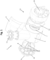
- Fig. 1 to 4 disclose an embodiment of a gas mixer 1 for an internal combustion engine 1 according to the present invention.
- Fig. 1 and Fig 2 show different perspective views of the gas mixer 1
- Fig. 3 discloses a side view of the gas mixer 1
- Fig. 4 a cross-section A-A indicated in Fig. 3 , wherein the interior of the gas mixer 1 along the center axis 9 can be seen.
- the gas mixer 1 comprises a base body 3 having a mixing volume 4, wherein the mixing volume 4 is configured for mixing an exhaust gas with air and fuel.
- the base body 3 is formed in such a way (which especially can be seen in Fig. 2 ) that the mixing volume 4 is formed cylindrically.
- the cylindrical shape of the mixing volume 4 is essentially rotationally symmetric regarding the center axis 9 of the base body 3.
- the gas mixer 1 comprises a first inlet opening 5, a second inlet opening 11 and an exhaust gas inlet opening 6.
- the exhaust gas inlet opening 6 is provided at a base body cover 16 of the base body 3, which can by connected and disconnected with the base body 3 by screw (or bolted) connections to release the mixing volume 4 and the mixing structure 8 regarding the environment.
- the first inlet opening 5 at the base body 3 is used for supplying air to the mixing volume 4.
- the second inlet opening 11 is used for supplying fuel to the mixing volume 4.
- exhaust gas inlet opening 6 is used for supplying exhaust gas to the mixing volume 4.
- the supplied air, fuel and exhaust gas is mixed inside the base body 3 of the gas mixer at the mixing volume 4, wherein the air-fuel-exhaust mixture is discharged from the mixing volume 4 of the base body via the discharge opening 7.
- the first inlet opening 5 and the second inlet opening 11 are arranged in such a way that supplied air and fuel via the first inlet opening 5 (supplying air) and the second inlet opening 11 (supplying fuel) are entering the base body 3 essentially transversely with respect to the center axis 9.
- the exhaust inlet opening 6 is arranged in the center of the base body, wherein a center axis of the exhaust inlet opening 6 is aligned with the center axis 9 of the base body.
- the gas mixer 1 furthermore comprises a mixing structure 8 at the base body 3, extending along a center axis 9 of the mixing volume 4 starting from the at least one exhaust gas inlet opening 6 projecting into the mixing volume 4 guiding the exhaust gases coming from the exhaust gas inlet opening 6 into the mixing volume 4.
- the mixing structure 8 surrounds the exhaust gas inlet opening 6 at the mixing volume 4 forming a tubular section having a circular cross section projecting into the mixing volume 4, wherein the center axis 9 of the mixing volume 4, the center axis of the mixing structure 8 and the center axis 9 of the at least one exhaust gas inlet opening 6 are aligned.
- exhaust gas is mixed with air and fuel before the exhaust gas gets in contact with the - perhaps cold - surface of the mixing volume 4 wall, inner wall of the base body 3 or other surfaces of components of the gas mixer 1.
- This direct supply of the exhaust gas into the center of the mixing volume 4 reduces the risk of a condensate forming, as the hot exhaust gas is prevented from directly contacting cold surfaces (e.g. the inner wall of the base body 3 during or after a cold start of the internal combustion engine 2).
- the mixing structure 8 comprises a plurality of openings 10 around the shell surface of the mixing structure 8, wherein the openings 10 fluidically connecting the exhaust gas inlet opening 6 and the mixing volume 4, wherein one more opening is provided at the mixing structure 8 symmetrically with the center axis 9 at an end of the mixing structure 8 facing away from the exhaust gas inlet opening 6.
- the mixing structure 8 has a decreasing cross-sectional area along the center axis 9 of the mixing structure 8. In this way exhaust gas can be supplied continuously along the mixing structure 8 along the center axis 9 into the air and fuel flow surrounding the mixing structure 8.
- the center axis 9 of the at least one exhaust gas inlet opening 6 and the at least one discharge opening 7 are aligned with the center axis 9 of the mixing volume 4.
- a particularly preferred helical flow pattern of the air-fuel-exhaust mixture is provided via the discharge opening 7, which especially generates an improved operation condition for the compressor 15 (if the compressor 15 is directly arranged at the discharge opening 7 as can be seen by the embodiment shown by Fig. 1 to 4 ).
- the compressor 16 comprises a compressor wheel 15 having a rotational axis 14 which is aligned with the center axis 9 of the mixing volume 4 and the center axis 9 of the at least one exhaust gas inlet opening 6.
- the compressor 16 is part of a turbocharger 13, wherein the compressor wheel 15 is connected and driven by a turbine wheel 17 of the turbocharger 13.
Landscapes
- Engineering & Computer Science (AREA)
- Chemical & Material Sciences (AREA)
- Combustion & Propulsion (AREA)
- Mechanical Engineering (AREA)
- General Engineering & Computer Science (AREA)
Abstract
Description
- The present invention concerns a gas mixer for an internal combustion engine with the features of the preamble of
claim 1, an arrangement of such a gas mixer and an internal combustion engine comprising such a gas mixer. - It is commonly known by the state of the art to use exhaust gas recirculation systems to reduce emissions of internal combustion engines, in particular nitrogen oxide emissions (NOx) .
- Nitrogen oxide is especially formed by high combustion peak temperatures (temperatures above 2300° K).
- A known way to reduce the nitrogen oxide emissions is to supply exhaust gases to the air or air-fuel-mixture provided for combustion, wherein the recirculated exhaust gas amount increases specific heat capacity of the mixture in the combustion chamber, which lowers the combustion peak temperature and the formed amount of nitrogen oxide emissions is reduced.
- If the exhaust gas of the combustion engine is fed back to the combustion engine outside of the combustion chamber, this is called an external exhaust gas recirculation system.
- Such systems in most cases use gas mixers for mixing the exhaust gas with charge air, air or an air-fuel-mixture provided for the combustion process.
- Gas mixers known by the state of the art for internal combustion engines comprise:
- a base body having a mixing volume, wherein the mixing volume is configured for mixing an exhaust gas with air or fuel or an air-fuel mixture,
- at least one first inlet opening at the base body for supplying air or an air-fuel mixture to the mixing volume,
- at least one exhaust gas inlet opening at the base body for supplying exhaust gas to the mixing volume and
- at least one discharge opening at the base body for discharging the mixture from the mixing volume of the base body.
- The disadvantage of such exhaust gas recirculation systems is the occurrence of condensation, especially during cold start and during engine start if the engine is located in low temperature environments (for example, sub-zero temperatures).
- In such cases, humidity in the recirculated exhaust gas tends to condensate at the cold surfaces of the gas mixer, which leads to droplet formation.
- Especially for low pressure exhaust gas recirculation systems, wherein exhaust gas is admixed to air or air and fuel upstream of a turbocharger or compressor, these droplets can lead to damages of the compressor wheel. However, droplets or condensate in the intake are obviously detrimental also in high pressure exhaust gas recirculation systems.
- The object of the present invention is therefore to provide a gas mixer for an internal combustion engine wherein the disadvantages of the state of the art previously explained can be at least partially improved and/or condensate formation can be reduced and/or a more efficient way can be generated to admix exhaust gas with air or an air-fuel-mixture.
- This object is achieved by a gas mixer having the features of
claim 1, an arrangement and an internal combustion engine comprising such a gas mixer. - According to the invention, it is provided that a gas mixer for an internal combustion engine comprises:
- a base body having a mixing volume, wherein the mixing volume is configured for mixing an exhaust gas with air or fuel or an air-fuel mixture,
- at least one first inlet opening at the base body for supplying air or air-fuel mixture to the mixing volume,
- at least one exhaust gas inlet opening at the base body for supplying exhaust gas to the mixing volume and
- at least one discharge opening at the base body for discharging the mixture from the mixing volume of the base body,
- Therefore, according to the present invention the exhaust gas is supplied via the at least one exhaust gas inlet and the mixing structure along the center axis of the mixing volume directly to the center of the mixing volume, wherein the exhaust gas can be prevented from directly contacting an inner wall of the base body before it is admixed to the air or air-fuel mixture.
- The center axis of the mixing volume could be thought of as the main direction of flow of the fluids in the mixing volume. According to a basic aspect of the invention the exhaust gas being recirculated enters the mixing volume through the at least one exhaust gas inlet at least approximately in the direction of the center axis (preferably aligned with the center axis) into the center of the mixing volume.
- This direct supply of the exhaust gas into the center of the mixing volume reduces the risk of a condensate forming, as the hot exhaust gas is prevented from directly contacting cold surfaces (e.g. the inner wall of the base body during or after a cold start of the internal combustion engine).
- The exhaust gas to be recirculated is expected to have a lower tendency towards condensation than the air, fuel, or air-fuel mixture with which it is to be mixed.
- According to a basic aspect of the invention the exhaust gas can become the carrier for the flow because of the exhaust gas to be recirculated enters the mixing volume along the center axis. Consequently, the mixing volume and the mixing structure can be designed such that the exhaust gas carries along the admixed air, fuel, or air-fuel mixture along a flow path which does not impinge onto relatively cold surfaces of the mixing volume which could potentially induce condensation and droplet formation.
- Furthermore, by usage of a mixing structure the mixing process of the exhaust gas admixed with air or air-fuel-mixture can be improved as the thermal and flow properties in the mixing volume can be affected.
- The supplying of the exhaust gas by usage of the mixing structure extending from the base body projecting into the mixing volume creates a dynamic fluidic condition inside the mixing volume, wherein the exhaust gas and the air or air-fuel-mixture can be mixed more efficiently.
- If the exhaust gas and the air or air-fuel-mixture are mixed in a more efficient and therefore faster way, a temperature compensation of the gas flows can also be done in a faster way, wherein the buildup of condensate can be reduced to a minimum.
- Already present internal combustion engines can be upgraded and operated with a gas mixer according to the invention. Therefore, the invention can be used for the embodiments of the prior art already described in the introduction of the description.
- The invention can particularly preferably be used in conjunction with an internal combustion engine driving a generator for creating electrical energy. Such combinations of internal combustion engines driving a generator are known as gensets.
- Advantageous embodiments are defined in the dependent claims.
- It can be provided that the mixing structure surrounds the at least one exhaust gas inlet opening at the inner structure forming a tubular section, which preferably comprises a circular cross section, projecting into the mixing volume.
- Preferably it can be provided that the tubular section of the mixing structure is provided with holes, especially bores, connecting the inner volume of the mixing structure with the surrounding mixing volume.
- It can be provided that the inner cross-sectional area of the mixing structure decreases, preferably partly according to a polynomial or linear function, along the center axis of the mixing structure.
- It can be provided that the mixing structure projects across the mixing volume and comprises an end at a center of an opposing discharge opening of the mixing volume regarding the at least one exhaust gas inlet opening.
- It can be provided that the mixing structure comprises at least one opening fluidically connecting the at least one exhaust gas inlet opening and the mixing volume.
- It can be provided that the center axis of the mixing volume and the mixing structure are essentially parallel, preferably aligned, with a center axis of the at least one exhaust gas inlet opening.
- It can be provided that the base body forms a cylindrical, preferably rotationally symmetric, mixing volume, particularly preferred wherein the center axis forms the rotational axis of the cylindrical mixing volume.
- It can be provided that a center axis of the at least one exhaust gas inlet opening and/or the at least one discharge opening is parallel, preferably aligned, with the center axis of the mixing volume.
- It can be provided that the at least one first inlet opening is arranged radially at the cylindrical mixing volume.
- It can be provided that the at least one first inlet opening is arranged in such a way that supplied air or air-fuel mixture via the at least one first inlet opening enters the base body essentially transversely with respect to the center axis.
- A preferred embodiment, wherein the at least one first inlet opening is arranged in such a way that supplied air or air-fuel mixture via the at least one first inlet opening enters the base body essentially transversely, can have the advantage that exhaust gas can be supplied in line with a center axis of the base body of the gas mixer, while the air and the fuel are supplied radially with respect to the exhaust gas. Because air or air-fuel-mixture is in such embodiments supplied into the mixing volume radially and the exhaust gas centrally, exhaust gas is mixed with air or air-fuel-mixture before the exhaust gas on its own comes into contact with the - perhaps cold - surface of the mixing volume wall, inner wall of the base body or other surfaces of components of the gas mixer.
- It can be provided that the at least one exhaust gas inlet opening is arranged in such a way that its center axis is parallel, preferably aligned, with a center axis of the at least one discharge opening.
- If the at least one exhaust gas inlet opening is arranged in such a way that its center axis is aligned with a center axis of the at least one discharge opening, the advanced embodiment is implemented, wherein the exhaust gas is directly supplied in direction of the at least one discharge opening without touching any - potentially cold - surfaces, wherein the risk of condensation is nearly eliminated, while at the same time the exhaust gas is properly mixed with the air or air-fuel-mixture inside the mixing volume.
- It can be provided that at least one second inlet opening at the base body for supplying fuel to the mixing volume is provided.
- Therefore, it can be provided that by use of
- the at least one first inlet opening air is supplied,
- the at least one exhaust inlet opening exhaust gas is supplied, and
- the at least one second inlet opening fuel is supplied
- It can be provided that the at least one second inlet opening is arranged in such a way that supplied fuel via the at least one second inlet opening enters the base body essentially transversely with respect to the center axis.
- Furthermore, protection is sought for an arrangement comprising a gas mixer according to the invention and a compressor, preferably of a turbocharger, of an internal combustion engine, wherein the compressor is fluidically connected to the at least one discharge opening of the gas mixer.
- It can be provided that a rotational axis of the compressor wheel of the compressor is parallel, preferably aligned, with the center axis of the mixing volume and/or a center axis of the at least one exhaust gas inlet opening.
- An advantage of such an embodiment is an improved thermodynamical balance of air-fuel-exhaust-mixture being compressed by the compressor, leading to decreased thermal gradients and therefore decreased thermal stresses of the compressor parts, especially the compressor wheels.
- Also, protection is sought for an internal combustion engine comprising a gas mixer according to the invention.
- Further details and advantages of the invention are apparent from the accompanying figures and the following description of the drawings. The figures show:
- Fig. 1
- an embodiment of a gas mixer according to the invention in a perspective view,
- Fig. 2
- the embodiment of
Fig. 1 in another perspective view, - Fig. 3
- the embodiment of the previous figures in a side view along the center axis, and
- Fig. 4
- a view of the cross-section A-A indicated at
Fig. 3 . -
Fig. 1 to 4 disclose an embodiment of agas mixer 1 for aninternal combustion engine 1 according to the present invention. -
Fig. 1 andFig 2 show different perspective views of thegas mixer 1, whereasFig. 3 discloses a side view of thegas mixer 1, andFig. 4 a cross-section A-A indicated inFig. 3 , wherein the interior of thegas mixer 1 along thecenter axis 9 can be seen. - The
gas mixer 1 comprises abase body 3 having a mixingvolume 4, wherein the mixingvolume 4 is configured for mixing an exhaust gas with air and fuel. - The
base body 3 is formed in such a way (which especially can be seen inFig. 2 ) that the mixingvolume 4 is formed cylindrically. - The cylindrical shape of the mixing
volume 4 is essentially rotationally symmetric regarding thecenter axis 9 of thebase body 3. - Furthermore, the
gas mixer 1 comprises afirst inlet opening 5, a second inlet opening 11 and an exhaustgas inlet opening 6. - The exhaust gas inlet opening 6 is provided at a
base body cover 16 of thebase body 3, which can by connected and disconnected with thebase body 3 by screw (or bolted) connections to release the mixingvolume 4 and the mixingstructure 8 regarding the environment. - The first inlet opening 5 at the
base body 3 is used for supplying air to the mixingvolume 4. - The second inlet opening 11 is used for supplying fuel to the mixing
volume 4. - And the exhaust gas inlet opening 6 is used for supplying exhaust gas to the mixing
volume 4. - The supplied air, fuel and exhaust gas is mixed inside the
base body 3 of the gas mixer at the mixingvolume 4, wherein the air-fuel-exhaust mixture is discharged from the mixingvolume 4 of the base body via thedischarge opening 7. - The
first inlet opening 5 and the second inlet opening 11 are arranged in such a way that supplied air and fuel via the first inlet opening 5 (supplying air) and the second inlet opening 11 (supplying fuel) are entering thebase body 3 essentially transversely with respect to thecenter axis 9. - In this way a helical flow of the air and the fuel inside the
cylindrical mixing volume 4 can be provided around thecenter axis 9 to mix the fuel with the air. - The exhaust inlet opening 6 is arranged in the center of the base body, wherein a center axis of the exhaust inlet opening 6 is aligned with the
center axis 9 of the base body. - The
gas mixer 1 furthermore comprises a mixingstructure 8 at thebase body 3, extending along acenter axis 9 of the mixingvolume 4 starting from the at least one exhaust gas inlet opening 6 projecting into the mixingvolume 4 guiding the exhaust gases coming from the exhaust gas inlet opening 6 into the mixingvolume 4. - The mixing
structure 8 surrounds the exhaust gas inlet opening 6 at the mixingvolume 4 forming a tubular section having a circular cross section projecting into the mixingvolume 4, wherein thecenter axis 9 of the mixingvolume 4, the center axis of the mixingstructure 8 and thecenter axis 9 of the at least one exhaust gas inlet opening 6 are aligned. - Because air and fuel are supplied into the mixing volume radially and the exhaust gas centrally, exhaust gas is mixed with air and fuel before the exhaust gas gets in contact with the - perhaps cold - surface of the mixing
volume 4 wall, inner wall of thebase body 3 or other surfaces of components of thegas mixer 1. - This direct supply of the exhaust gas into the center of the mixing
volume 4 reduces the risk of a condensate forming, as the hot exhaust gas is prevented from directly contacting cold surfaces (e.g. the inner wall of thebase body 3 during or after a cold start of the internal combustion engine 2). - The mixing
structure 8 comprises a plurality ofopenings 10 around the shell surface of the mixingstructure 8, wherein theopenings 10 fluidically connecting the exhaustgas inlet opening 6 and the mixingvolume 4, wherein one more opening is provided at the mixingstructure 8 symmetrically with thecenter axis 9 at an end of the mixingstructure 8 facing away from the exhaustgas inlet opening 6. - As can be seen in
Fig. 4 the mixingstructure 8 has a decreasing cross-sectional area along thecenter axis 9 of the mixingstructure 8. In this way exhaust gas can be supplied continuously along the mixingstructure 8 along thecenter axis 9 into the air and fuel flow surrounding the mixingstructure 8. - The
center axis 9 of the at least one exhaustgas inlet opening 6 and the at least onedischarge opening 7 are aligned with thecenter axis 9 of the mixingvolume 4. - As the
center axis 9 of thebase body 3 is aligned with the center axis of thedischarge opening 7, a particularly preferred helical flow pattern of the air-fuel-exhaust mixture is provided via thedischarge opening 7, which especially generates an improved operation condition for the compressor 15 (if thecompressor 15 is directly arranged at thedischarge opening 7 as can be seen by the embodiment shown byFig. 1 to 4 ). - The
compressor 16 comprises acompressor wheel 15 having arotational axis 14 which is aligned with thecenter axis 9 of the mixingvolume 4 and thecenter axis 9 of the at least one exhaustgas inlet opening 6. - The
compressor 16 is part of aturbocharger 13, wherein thecompressor wheel 15 is connected and driven by aturbine wheel 17 of theturbocharger 13. -
- 1
- gas mixer
- 2
- internal combustion engine
- 3
- base body
- 4
- mixing volume
- 5
- first inlet opening
- 6
- exhaust gas inlet opening
- 7
- discharge opening
- 8
- mixing structure
- 9
- center axis
- 10
- opening of the mixing structure
- 11
- second inlet opening
- 12
- compressor
- 13
- turbocharger
- 14
- rotational axis of the compressor
- 15
- compressor wheel
- 16
- base body cover
- 17
- turbine wheel
- 18
- turbine exhaust gas outlet
Claims (15)
- Gas mixer for an internal combustion engine (2), comprising:- a base body (3) having a mixing volume (4), wherein the mixing volume (4) is configured for mixing an exhaust gas with air or fuel or an air-fuel mixture,- at least one first inlet opening (5) at the base body (3) for supplying air or air-fuel mixture to the mixing volume (4),- at least one exhaust gas inlet opening (6) at the base body (3) for supplying exhaust gas to the mixing volume (4) and- at least one discharge opening (7) at the base body (3) for discharging the mixture from the mixing volume (4) of the base body (3),characterized in that a mixing structure (8) is provided at the base body (3), extending along a center axis (9) of the mixing volume (4) starting from the at least one exhaust gas inlet opening (6) projecting into the mixing volume (4).
- Gas mixer according to claim 1, wherein the mixing structure (8) surrounds the at least one exhaust gas inlet opening (6) at the mixing volume (4) forming a tubular section, preferably comprises a circular cross section, projecting into the mixing volume (4).
- Gas mixer according to claim 2, wherein the inner cross-sectional area of the mixing structure (8) decreases, preferably partly according to a polynomial or linear function, along the center axis (9) of the mixing structure (8).
- Gas mixer according to claim 2 or 3, wherein the mixing structure (8) comprises at least one opening (10) fluidically connecting the at least one exhaust gas inlet opening (6) and the mixing volume (4).
- Gas mixer according to at least one of the preceding claims, wherein the center axis (9) of the mixing volume (4) and the mixing structure (8) is essentially parallel, preferably aligned, with a center axis (9) of the at least one exhaust gas inlet opening (6).
- Gas mixer according to at least one of the preceding claims, wherein the base body (3) forms a cylindrical, preferably rotationally symmetric, mixing volume (4).
- Gas mixer according to at least one of the preceding claims, wherein a center axis (9) of the at least one exhaust gas inlet opening (6) and/or the at least one discharge opening (7) is parallel, preferably aligned, with the center axis (9) of the mixing volume (4).
- Gas mixer according to at least one of the preceding claims, wherein the at least one first inlet opening (5) is arranged radially at the cylindrical mixing volume (4) .
- Gas mixer according to at least one of the preceding claims, wherein the at least one first inlet opening (5) is arranged in such a way that supplied air or air-fuel mixture via the at least one first inlet opening (5) enters the base body (3) essentially transversely with respect to the center axis (9).
- Gas mixer according to at least one of the preceding claims, wherein the at least one exhaust gas inlet opening (6) is arranged in such a way that its center axis (9) is parallel, preferably aligned, with a center axis (9) of the at least one discharge opening (7).
- Gas mixer according to at least one of the preceding claims, wherein at least one second inlet opening (11) at the base body (3) for supplying fuel to the mixing volume (4) is provided.
- Gas mixer according claim 11, wherein the at least one second inlet opening (11) is arranged in such a way that supplied fuel via the at least one second inlet opening (11) enters the base body (3) essentially transversely with respect to the center axis (9).
- Arrangement comprising a gas mixer (1) according to at least one of the preceding claims and a compressor (12), preferably of a turbocharger (13), of an internal combustion engine (2), wherein the compressor (12) is fluidically connected to the at least one discharge opening (7) of the gas mixer (1).
- Arrangement according to claim 13, wherein a rotational axis (14) of the compressor wheel (15) of the compressor (12) is parallel, preferably aligned, with the center axis (9) of the mixing volume (4) and/or a center axis (9) of the at least one exhaust gas inlet opening (6).
- Internal combustion engine comprising a gas mixer (1) according to at least one of the claims 1 to 12 and/or an arrangement according to claim 13 or 14.
Priority Applications (1)
| Application Number | Priority Date | Filing Date | Title |
|---|---|---|---|
| EP23150882.1A EP4400710A1 (en) | 2023-01-10 | 2023-01-10 | Gas mixer for an internal combustion engine |
Applications Claiming Priority (1)
| Application Number | Priority Date | Filing Date | Title |
|---|---|---|---|
| EP23150882.1A EP4400710A1 (en) | 2023-01-10 | 2023-01-10 | Gas mixer for an internal combustion engine |
Publications (1)
| Publication Number | Publication Date |
|---|---|
| EP4400710A1 true EP4400710A1 (en) | 2024-07-17 |
Family
ID=84901486
Family Applications (1)
| Application Number | Title | Priority Date | Filing Date |
|---|---|---|---|
| EP23150882.1A Pending EP4400710A1 (en) | 2023-01-10 | 2023-01-10 | Gas mixer for an internal combustion engine |
Country Status (1)
| Country | Link |
|---|---|
| EP (1) | EP4400710A1 (en) |
Citations (5)
| Publication number | Priority date | Publication date | Assignee | Title |
|---|---|---|---|---|
| DE2925495A1 (en) * | 1979-06-23 | 1981-01-22 | Bosch Pierburg System Ohg | Fuel injection vaporiser for IC engine - uses injection into exhaust gas upstream of junction of exhaust gas and fresh air |
| JP2008232091A (en) * | 2007-03-23 | 2008-10-02 | Nissan Diesel Motor Co Ltd | Exhaust gas recirculation device for internal combustion engine with supercharger |
| US20090071150A1 (en) * | 2006-01-27 | 2009-03-19 | Borgwarner Inc. | Mixing Unit for LP-EGR Condensate Into the Compressor |
| EP2666989A1 (en) * | 2011-01-19 | 2013-11-27 | Mitsubishi Heavy Industries, Ltd. | Supercharger and diesel engine provided with same |
| US20200256266A1 (en) * | 2019-02-07 | 2020-08-13 | Woodward, Inc. | Modular exhaust gas recirculation system |
-
2023
- 2023-01-10 EP EP23150882.1A patent/EP4400710A1/en active Pending
Patent Citations (5)
| Publication number | Priority date | Publication date | Assignee | Title |
|---|---|---|---|---|
| DE2925495A1 (en) * | 1979-06-23 | 1981-01-22 | Bosch Pierburg System Ohg | Fuel injection vaporiser for IC engine - uses injection into exhaust gas upstream of junction of exhaust gas and fresh air |
| US20090071150A1 (en) * | 2006-01-27 | 2009-03-19 | Borgwarner Inc. | Mixing Unit for LP-EGR Condensate Into the Compressor |
| JP2008232091A (en) * | 2007-03-23 | 2008-10-02 | Nissan Diesel Motor Co Ltd | Exhaust gas recirculation device for internal combustion engine with supercharger |
| EP2666989A1 (en) * | 2011-01-19 | 2013-11-27 | Mitsubishi Heavy Industries, Ltd. | Supercharger and diesel engine provided with same |
| US20200256266A1 (en) * | 2019-02-07 | 2020-08-13 | Woodward, Inc. | Modular exhaust gas recirculation system |
Similar Documents
| Publication | Publication Date | Title |
|---|---|---|
| EP0692083B1 (en) | Injector having low tip temperature | |
| EP0590699B1 (en) | Burner for heating exhaust gas | |
| US7640752B2 (en) | Device for guiding an element in an orifice in a wall of a turbomachine combustion chamber | |
| CN100416063C (en) | Layered Fuel Ribbons for Fuel Injectors | |
| EP1908940B1 (en) | Multi-conduit fuel manifold and method of manufacture | |
| US7299620B2 (en) | Tornado torch igniter | |
| US4684341A (en) | Fuel vaporization apparatus for combustor | |
| US10816208B2 (en) | Fuel injectors and methods of fabricating same | |
| RU2296917C2 (en) | Ring combustion chamber | |
| US12416268B2 (en) | Method for operating an internal combustion engine, and internal combustion engine | |
| US20250230762A1 (en) | Burner for an exhaust-gas aftertreatment system, and exhaust-gas aftertreatment system for an internal combustion engine comprising such a burner | |
| US6820864B2 (en) | Fuel vaporization promoting apparatus and fuel carburetion accelerator | |
| US20090019837A1 (en) | Exhaust purification device for engine | |
| CN107975821B (en) | Gas turbine combustor | |
| US20030010033A1 (en) | Injector with active cooling | |
| US10344646B2 (en) | Exhaust gas burner assembly | |
| EP4411239B1 (en) | Hydrogen fuel distributor | |
| US5058374A (en) | Injector | |
| WO1999027305A1 (en) | Catalytic combustor for gas turbines | |
| US12247513B2 (en) | Combustion engine for a motor vehicle, in particular for a car, and motor vehicle | |
| EP3988846B1 (en) | Integrated combustion nozzle having a unified head end | |
| US9506385B2 (en) | Fuel fired burner for vehicle exhaust component | |
| GB2621250A (en) | Exhaust system of a combustion engine | |
| JPH01114608A (en) | Pilot burner for device for burning solid grain of exhaust gas from internal combustion engine | |
| CN118510618A (en) | Multiphase fuel injector |
Legal Events
| Date | Code | Title | Description |
|---|---|---|---|
| PUAI | Public reference made under article 153(3) epc to a published international application that has entered the european phase |
Free format text: ORIGINAL CODE: 0009012 |
|
| STAA | Information on the status of an ep patent application or granted ep patent |
Free format text: STATUS: THE APPLICATION HAS BEEN PUBLISHED |
|
| AK | Designated contracting states |
Kind code of ref document: A1 Designated state(s): AL AT BE BG CH CY CZ DE DK EE ES FI FR GB GR HR HU IE IS IT LI LT LU LV MC ME MK MT NL NO PL PT RO RS SE SI SK SM TR |
|
| STAA | Information on the status of an ep patent application or granted ep patent |
Free format text: STATUS: REQUEST FOR EXAMINATION WAS MADE |
|
| 17P | Request for examination filed |
Effective date: 20250116 |
|
| STAA | Information on the status of an ep patent application or granted ep patent |
Free format text: STATUS: EXAMINATION IS IN PROGRESS |
|
| 17Q | First examination report despatched |
Effective date: 20260302 |