EP4400706A1 - Engine control device and engine system - Google Patents
Engine control device and engine system Download PDFInfo
- Publication number
- EP4400706A1 EP4400706A1 EP22880974.5A EP22880974A EP4400706A1 EP 4400706 A1 EP4400706 A1 EP 4400706A1 EP 22880974 A EP22880974 A EP 22880974A EP 4400706 A1 EP4400706 A1 EP 4400706A1
- Authority
- EP
- European Patent Office
- Prior art keywords
- engine
- charge air
- air amount
- ignition timing
- insufficiency
- Prior art date
- Legal status (The legal status is an assumption and is not a legal conclusion. Google has not performed a legal analysis and makes no representation as to the accuracy of the status listed.)
- Pending
Links
Images


Classifications
-
- F—MECHANICAL ENGINEERING; LIGHTING; HEATING; WEAPONS; BLASTING
- F02—COMBUSTION ENGINES; HOT-GAS OR COMBUSTION-PRODUCT ENGINE PLANTS
- F02P—IGNITION, OTHER THAN COMPRESSION IGNITION, FOR INTERNAL-COMBUSTION ENGINES; TESTING OF IGNITION TIMING IN COMPRESSION-IGNITION ENGINES
- F02P5/00—Advancing or retarding ignition; Control therefor
- F02P5/04—Advancing or retarding ignition; Control therefor automatically, as a function of the working conditions of the engine or vehicle or of the atmospheric conditions
- F02P5/145—Advancing or retarding ignition; Control therefor automatically, as a function of the working conditions of the engine or vehicle or of the atmospheric conditions using electrical means
- F02P5/15—Digital data processing
- F02P5/152—Digital data processing dependent on pinking
-
- F—MECHANICAL ENGINEERING; LIGHTING; HEATING; WEAPONS; BLASTING
- F02—COMBUSTION ENGINES; HOT-GAS OR COMBUSTION-PRODUCT ENGINE PLANTS
- F02D—CONTROLLING COMBUSTION ENGINES
- F02D37/00—Non-electrical conjoint control of two or more functions of engines, not otherwise provided for
- F02D37/02—Non-electrical conjoint control of two or more functions of engines, not otherwise provided for one of the functions being ignition
-
- F—MECHANICAL ENGINEERING; LIGHTING; HEATING; WEAPONS; BLASTING
- F02—COMBUSTION ENGINES; HOT-GAS OR COMBUSTION-PRODUCT ENGINE PLANTS
- F02D—CONTROLLING COMBUSTION ENGINES
- F02D41/00—Electrical control of supply of combustible mixture or its constituents
- F02D41/0002—Controlling intake air
-
- F—MECHANICAL ENGINEERING; LIGHTING; HEATING; WEAPONS; BLASTING
- F02—COMBUSTION ENGINES; HOT-GAS OR COMBUSTION-PRODUCT ENGINE PLANTS
- F02D—CONTROLLING COMBUSTION ENGINES
- F02D41/00—Electrical control of supply of combustible mixture or its constituents
- F02D41/0002—Controlling intake air
- F02D41/0007—Controlling intake air for control of turbo-charged or super-charged engines
-
- F—MECHANICAL ENGINEERING; LIGHTING; HEATING; WEAPONS; BLASTING
- F02—COMBUSTION ENGINES; HOT-GAS OR COMBUSTION-PRODUCT ENGINE PLANTS
- F02D—CONTROLLING COMBUSTION ENGINES
- F02D41/00—Electrical control of supply of combustible mixture or its constituents
- F02D41/24—Electrical control of supply of combustible mixture or its constituents characterised by the use of digital means
- F02D41/2406—Electrical control of supply of combustible mixture or its constituents characterised by the use of digital means using essentially read only memories
- F02D41/2409—Addressing techniques specially adapted therefor
- F02D41/2422—Selective use of one or more tables
-
- F—MECHANICAL ENGINEERING; LIGHTING; HEATING; WEAPONS; BLASTING
- F02—COMBUSTION ENGINES; HOT-GAS OR COMBUSTION-PRODUCT ENGINE PLANTS
- F02P—IGNITION, OTHER THAN COMPRESSION IGNITION, FOR INTERNAL-COMBUSTION ENGINES; TESTING OF IGNITION TIMING IN COMPRESSION-IGNITION ENGINES
- F02P5/00—Advancing or retarding ignition; Control therefor
- F02P5/04—Advancing or retarding ignition; Control therefor automatically, as a function of the working conditions of the engine or vehicle or of the atmospheric conditions
- F02P5/145—Advancing or retarding ignition; Control therefor automatically, as a function of the working conditions of the engine or vehicle or of the atmospheric conditions using electrical means
-
- F—MECHANICAL ENGINEERING; LIGHTING; HEATING; WEAPONS; BLASTING
- F02—COMBUSTION ENGINES; HOT-GAS OR COMBUSTION-PRODUCT ENGINE PLANTS
- F02P—IGNITION, OTHER THAN COMPRESSION IGNITION, FOR INTERNAL-COMBUSTION ENGINES; TESTING OF IGNITION TIMING IN COMPRESSION-IGNITION ENGINES
- F02P5/00—Advancing or retarding ignition; Control therefor
- F02P5/04—Advancing or retarding ignition; Control therefor automatically, as a function of the working conditions of the engine or vehicle or of the atmospheric conditions
- F02P5/145—Advancing or retarding ignition; Control therefor automatically, as a function of the working conditions of the engine or vehicle or of the atmospheric conditions using electrical means
- F02P5/15—Digital data processing
-
- F—MECHANICAL ENGINEERING; LIGHTING; HEATING; WEAPONS; BLASTING
- F02—COMBUSTION ENGINES; HOT-GAS OR COMBUSTION-PRODUCT ENGINE PLANTS
- F02P—IGNITION, OTHER THAN COMPRESSION IGNITION, FOR INTERNAL-COMBUSTION ENGINES; TESTING OF IGNITION TIMING IN COMPRESSION-IGNITION ENGINES
- F02P5/00—Advancing or retarding ignition; Control therefor
- F02P5/04—Advancing or retarding ignition; Control therefor automatically, as a function of the working conditions of the engine or vehicle or of the atmospheric conditions
- F02P5/145—Advancing or retarding ignition; Control therefor automatically, as a function of the working conditions of the engine or vehicle or of the atmospheric conditions using electrical means
- F02P5/15—Digital data processing
- F02P5/1502—Digital data processing using one central computing unit
- F02P5/1504—Digital data processing using one central computing unit with particular means during a transient phase, e.g. acceleration, deceleration, gear change
-
- F—MECHANICAL ENGINEERING; LIGHTING; HEATING; WEAPONS; BLASTING
- F02—COMBUSTION ENGINES; HOT-GAS OR COMBUSTION-PRODUCT ENGINE PLANTS
- F02D—CONTROLLING COMBUSTION ENGINES
- F02D2200/00—Input parameters for engine control
- F02D2200/02—Input parameters for engine control the parameters being related to the engine
- F02D2200/04—Engine intake system parameters
- F02D2200/0406—Intake manifold pressure
-
- F—MECHANICAL ENGINEERING; LIGHTING; HEATING; WEAPONS; BLASTING
- F02—COMBUSTION ENGINES; HOT-GAS OR COMBUSTION-PRODUCT ENGINE PLANTS
- F02D—CONTROLLING COMBUSTION ENGINES
- F02D2200/00—Input parameters for engine control
- F02D2200/02—Input parameters for engine control the parameters being related to the engine
- F02D2200/04—Engine intake system parameters
- F02D2200/0414—Air temperature
-
- F—MECHANICAL ENGINEERING; LIGHTING; HEATING; WEAPONS; BLASTING
- F02—COMBUSTION ENGINES; HOT-GAS OR COMBUSTION-PRODUCT ENGINE PLANTS
- F02D—CONTROLLING COMBUSTION ENGINES
- F02D41/00—Electrical control of supply of combustible mixture or its constituents
- F02D41/02—Circuit arrangements for generating control signals
- F02D41/18—Circuit arrangements for generating control signals by measuring intake air flow
-
- Y—GENERAL TAGGING OF NEW TECHNOLOGICAL DEVELOPMENTS; GENERAL TAGGING OF CROSS-SECTIONAL TECHNOLOGIES SPANNING OVER SEVERAL SECTIONS OF THE IPC; TECHNICAL SUBJECTS COVERED BY FORMER USPC CROSS-REFERENCE ART COLLECTIONS [XRACs] AND DIGESTS
- Y02—TECHNOLOGIES OR APPLICATIONS FOR MITIGATION OR ADAPTATION AGAINST CLIMATE CHANGE
- Y02T—CLIMATE CHANGE MITIGATION TECHNOLOGIES RELATED TO TRANSPORTATION
- Y02T10/00—Road transport of goods or passengers
- Y02T10/10—Internal combustion engine [ICE] based vehicles
- Y02T10/12—Improving ICE efficiencies
-
- Y—GENERAL TAGGING OF NEW TECHNOLOGICAL DEVELOPMENTS; GENERAL TAGGING OF CROSS-SECTIONAL TECHNOLOGIES SPANNING OVER SEVERAL SECTIONS OF THE IPC; TECHNICAL SUBJECTS COVERED BY FORMER USPC CROSS-REFERENCE ART COLLECTIONS [XRACs] AND DIGESTS
- Y02—TECHNOLOGIES OR APPLICATIONS FOR MITIGATION OR ADAPTATION AGAINST CLIMATE CHANGE
- Y02T—CLIMATE CHANGE MITIGATION TECHNOLOGIES RELATED TO TRANSPORTATION
- Y02T10/00—Road transport of goods or passengers
- Y02T10/10—Internal combustion engine [ICE] based vehicles
- Y02T10/40—Engine management systems
Definitions
- PTL 1 discloses an engine device for the purpose of suppressing a decrease in thermal efficiency at the same time as implementing a stable engine operation.
- the engine device is provided with a control unit that determines whether or not a charge air amount (asupplied air amount of an engine) in premixed combustion in a cylinder is insufficient, in which the control unit is configured to suppress knocking of the engine by performing a retarding control of an ignition timing of an ignition device stepwise in a case where it is determined that the charge air amount is insufficient.
- a purpose of at least one embodiment of the present disclosure is to provide an engine control device that can quickly improve insufficiency of charge air amount and an engine system provided with the engine control device.
- expressions such as "identical”, “equal”, and “homogeneous” representing a state of equality between objects not only represent a state of equality in a strict sense but also represent a state where allowance or a difference to an extent in which the same function is obtained is present.
- expressions representing shapes such as a quadrangular shape and a cylindrical shape not only represent shapes such as a quadrangular shape and a cylindrical shape in a geometrically strict sense but also represent shapes including a rough portion, a chamfered portion, and the like within a scope in which the same effect is obtained.
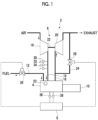
- Fig. 1 is a schematic diagram illustrating a configuration of an engine system 2 according to one embodiment.
- the engine system 2 illustrated in Fig. 1 is provided with an engine 4, a turbocharger 6 that pressurizes charge air of the engine 4, and an engine control device 8 that controls the engine 4.
- the engine 4 is an engine with a turbocharger for power generation
- the engine system 2 is provided with a generator 10 that is driven to generate power by the engine 4.
- the engine system 2 is provided with a fuel supply pipe 12 for supplying fuel to the engine 4, an intake manifold 14 connected to an intake side of the engine 4, and an exhaust manifold 16 connected to an exhaust side of the engine 4.
- a waste gate pipe 24 that bypasses the exhaust turbine 20 is provided in the exhaust manifold 16.
- a waste gate valve 28 that can adjust a flow rate of the exhaust flowing through the waste gate pipe 24 is provided in the waste gate pipe 24.
- a flow regulation valve 26 is provided in the fuel supply pipe 12.
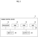
- Fig. 2 is a diagram illustrating an example of a hardware configuration of the engine control device 8 illustrated in Fig. 1 .
- the parameter acquisition unit 40 acquires each of the charge air pressure Ps measured by the charge air pressure sensor 30, the charge air temperature Ts measured by the charge air temperature sensor 32, the charge air amount Ga of the engine 4 measured by the charge air flow meter 34, the rotation speed Ne of the engine 4 measured by the engine speed sensor 36, and the load L of the engine 4 measured by the load sensor 38 from each sensor.
- the charge air amount control unit 42 controls the charge air amount of the engine 4 by setting a required air amount Sa of the engine 4 based on the charge air pressure Ps, the charge air temperature Ts, the engine speed Ne, and the load L of the engine 4 acquired by the parameter acquisition unit 40 and controlling the opening degree of the waste gate valve 28 based on the set required air amount Sa.
- the required air amount of the engine 4 means a target value of the charge air amount of the engine 4.
- the ignition timing determination unit 50 determines the ignition timing Ti of the engine 4 corresponding to the load L of the engine acquired by the parameter acquisition unit 40 based on the load L of the engine acquired by the parameter acquisition unit 40 and on the ignition timing map Mi selected by the ignition timing map selection unit 48.
- the charge air amount insufficiency determination unit 46 calculates a ratio Ga/Sa of the charge air amount Ga (a measurement value of the charge air amount) of the engine 4 measured by the charge air flow meter 34 to the required air amount Sa of the engine 4 set by the charge air amount control unit 42.
- whether the current state of the ignition timing map selection unit 48 is a state where the first map Mi1 is selected or a state where the second map Mi2 is selected is determined. In a case where the current state of the ignition timing map selection unit 48 is the state where the first map Mi1 is selected, a transition is made to S103a. In a case where the current state of the ignition timing map selection unit 48 is the state where the second map Mi2 is selected, a transition is made to S103b.
- the charge air amount insufficiency determination unit 46 determines whether or not the ratio Ga/Sa calculated in S101 is less than or equal to a threshold value Rth1 (first threshold value). In a case where the ratio Ga/Sa is less than or equal to the threshold value Rth1, the charge air amount insufficiency determination unit 46 determines that the insufficiency of the charge air amount has occurred, and the ignition timing map selection unit 48 selects the second map Mi2 in S104a. That is, in S104a, the ignition timing map selection unit 48 switches the ignition timing map Mi to be selected from the first map Mi1 to the second map Mi2.
- the charge air amount insufficiency determination unit 46 determines whether or not the ratio Ga/Sa calculated in S101 is greater than or equal to a threshold value Rth2 (second threshold value). In a case where the ratio Ga/Sa is greater than or equal to the threshold value Rth2, the charge air amount insufficiency determination unit 46 determines that the insufficiency of the charge air amount has not occurred (the insufficiency of the charge air amount is solved), and the ignition timing map selection unit 48 selects the first map Mi1 in S104b. That is, in S104b, the ignition timing map selection unit 48 switches the ignition timing map Mi to be selected from the second map Mi2 to the first map Mi1.
- the threshold value Rth2 is a value greater than the threshold value Rth1, and Rth1 may be, for example, a value less than or equal to 950 of Rth2.
- the charge air amount insufficiency determination unit 46 determines whether or not a state where the ratio Ga/Sa calculated in S201 is greater than or equal to the threshold value Rth2 continues for a predetermined time set in advance or longer. In a case where the state where the ratio Ga/Sa is greater than or equal to the threshold value Rth2 continues for the predetermined time set in advance or longer, the charge air amount insufficiency determination unit 46 determines that the insufficiency of the charge air amount has not occurred (the insufficiency of the charge air amount is solved), and the ignition timing map selection unit 48 selects the first map Mi1 in S204b.
- the ignition timing map selection unit 48 switches the ignition timing map to be selected from the second map Mi2 to the first map Mi1.
- the threshold value Rth2 is a value greater than the threshold value Rth1, and Rth1 may be, for example, a value less than or equal to 950 of Rth2.
- the ignition timing determination unit 50 determines the ignition timing Ti during the combustion cycle of the engine 4 using the ignition timing map Mi (in the illustrated example, the first map Mi1 or the second map Mi2) selected in S204a or in S204b by the ignition timing map selection unit 48. More specifically, the ignition timing determination unit 50 determines the ignition timing Ti of the engine 4 corresponding to the load L of the engine 4 acquired by the parameter acquisition unit 40 based on the load L of the engine 4 acquired by the parameter acquisition unit 40 and on the ignition timing map Mi selected in S204a or in S204b by the ignition timing map selection unit 48. In S206, the ignition timing control unit 52 controls the ignition timing Ti of the engine 4 for the ignition device 23 of the engine 4 based on the ignition timing Ti determined in S205, as described above.
- the ignition timing control unit 52 controls the ignition timing Ti of the engine 4 for the ignition device 23 of the engine 4 based on the ignition timing Ti determined in S205, as described above.
- the charge air amount insufficiency determination unit 46 determines that the insufficiency of the charge air amount has occurred in the state where the first map Mi1 is selected (for example, in the example illustrated in Fig. 5 , in a case where the ratio Ga/Sa of the measurement value Ga of the charge air amount to the required air amount Sa of the engine 4 is less than or equal to the threshold value Rth1)
- the ignition timing Ti of the engine 4 is changed to the retarded side based on the second map Mi2 by switching the ignition timing map Mi to be selected from the first map Mi1 to the second map Mi2. Accordingly, thermal efficiency of the engine 4 is decreased, and this leads to an increase in exhaust energy of the engine 4 and to an increase in drive energy of the turbocharger 6.
- the insufficiency of the charge air amount can be quickly improved.
- a combustion speed of the engine 4 is decreased, and occurrence of knocking can be suppressed.
- the ignition timing map Mi having a low risk of a misfire in the storage unit 47 in advance and selecting the ignition timing map Mi, occurrence of a misfire and the like caused by excessive retarding can be suppressed.
- Da is the charge air density (kg/m 3 )
- Ps is the charge air pressure (MPa_abs)
- Ts is the charge air temperature (°C).
- Ga is the charge air amount (kg/h) of the engine 4
- Ne is the engine speed (min -1 ) of the engine 4
- N is the number of cylinders of the engine 4
- D is a cylinder capacity (m 3 ) per cylinder
- ⁇ v is volumetric efficiency (a ratio of air trapped in the cylinder) of the engine 4.
- the estimation value of the charge air amount Ga of the engine 4 used for determining the insufficiency of the charge air amount of the engine 4 may be estimated based on properties of the exhaust of the engine 4. For example, in a case where the engine system 2 is provided with a concentration sensor (not illustrated) that measures an O 2 concentration in the exhaust of the exhaust manifold 16, the estimation value of the charge air amount Ga of the engine 4 may be calculated based on a measurement value of the O 2 concentration in the exhaust and on a measurement value of a fuel flow rate.
- the charge air amount insufficiency determination unit 46 may determine that the insufficiency of the charge air amount has occurred in a case where the opening degree of the waste gate valve 28 is in a fully closed position. In this case, the charge air amount insufficiency determination unit 46 may determine that the insufficiency of the charge air amount has not occurred in a case where the opening degree of the waste gate valve 28 is not in the fully closed position.
- the charge air amount of the engine 4 is increased as the opening degree of the waste gate valve 28 is decreased.
- the opening degree of the waste gate valve 28 since the charge air amount of the engine 4 cannot be further increased by controlling the waste gate valve 28, it can be determined that the insufficiency of the charge air amount of the engine 4 has occurred. Even in this case, the same manner as the embodiment described using Figs. 5 and 6 and the like may be applied.
- the ignition timing may be determined using the second map Mi2 in a case where the charge air amount insufficiency determination unit 46 determines that the insufficiency of the charge air amount of the engine 4 has occurred, and the ignition timing may be determined using the first map Mi1 in a case where the charge air amount insufficiency determination unit 46 determines that the insufficiency of the charge air amount of the engine 4 has not occurred.
- a charge air bypass pipe 56 for releasing the intake of the engine 4 from a space between the compressor 18 of the turbocharger 6 and the engine 4 may be connected to the intake manifold 14 connected to the intake side of the engine 4.
- a charge air bypass valve 58 is provided in the charge air bypass pipe 56.
- the charge air amount insufficiency determination unit 46 may determine that the insufficiency of the charge air amount has occurred in a case where the opening degree of the charge air bypass valve 58 is in a fully closed position. In this case, the charge air amount insufficiency determination unit 46 may determine that the insufficiency of the charge air amount has not occurred in a case where the opening degree of the charge air bypass valve 58 is not in the fully closed position.
- the charge air amount of the engine 4 is increased as the opening degree of the charge air bypass valve 58 is decreased.
- the charge air amount of the engine 4 cannot be further increased by controlling the charge air bypass valve 58, and it can be determined that the insufficiency of the charge air amount of the engine 4 has occurred. Even in this case, the same manner as the embodiment described using Figs. 5 and 6 and the like may be applied.
- the ignition timing may be determined using the second map Mi2 in a case where the charge air amount insufficiency determination unit 46 determines that the insufficiency of the charge air amount of the engine 4 has occurred, and the ignition timing may be determined using the first map Mi1 in a case where the charge air amount insufficiency determination unit 46 determines that the insufficiency of the charge air amount of the engine 4 has not occurred.
- the charge air amount of the engine 4 is increased as the opening degree of the intake throttle valve 60 is increased.
- the opening degree of the intake throttle valve 60 is in the fully open position, the charge air amount of the engine 4 cannot be further increased by controlling the intake throttle valve 60, and it can be determined that the insufficiency of the charge air amount of the engine 4 has occurred. Even in this case, the same manner as the embodiment described using Figs. 5 and 6 and the like may be applied.
- the ignition timing may be determined using the second map Mi2 in a case where the charge air amount insufficiency determination unit 46 determines that the insufficiency of the charge air amount of the engine 4 has occurred, and the ignition timing may be determined using the first map Mi1 in a case where the charge air amount insufficiency determination unit 46 determines that the insufficiency of the charge air amount of the engine 4 has not occurred.
- the charge air amount insufficiency determination unit 46 may determine that the insufficiency of the charge air amount has occurred in a case where the opening degree of the intake throttle valve 60 is extremely high with respect to the operation state of the engine 4, that is, in a case where the opening degree of the intake throttle valve 60 is greater than a reference value of the opening degree of the intake throttle valve 60 corresponding to the operation state of the engine 4 (for example, the rotation speed and output of the engine 4 and an outside air condition of the engine 4).
- the ignition timing may be determined using the second map Mi2 in a case where the charge air amount insufficiency determination unit 46 determines that the insufficiency of the charge air amount of the engine 4 has occurred, and the ignition timing may be determined using the first map Mi1 in a case where the charge air amount insufficiency determination unit 46 determines that the insufficiency of the charge air amount of the engine 4 has not occurred.
- the engine control device 8 may be configured to execute a retarding control of retarding the ignition timing of the engine 4 with respect to a reference timing in order to avoid abnormal combustion of the engine 4.
- the charge air amount insufficiency determination unit 46 may determine that the insufficiency of the charge air amount has occurred in a case where the ignition timing of the engine 4 (particularly, ignition timings of a plurality of cylinders) is maintained at an ignition timing corresponding to a limit value of an amount of retarding from the reference timing for a predetermined time or longer.
- the charge air amount insufficiency determination unit 46 may determine that the insufficiency of the charge air amount has not occurred in a case where the ignition timing of the engine 4 is not maintained at the ignition timing corresponding to the limit value of the amount of retarding from the reference timing for the predetermined time or longer. Even in this case, the same manner as the embodiment described using Figs. 5 and 6 and the like may be applied.
- the ignition timing may be determined using the second map Mi2 in a case where the charge air amount insufficiency determination unit 46 determines that the insufficiency of the charge air amount of the engine 4 has occurred, and the ignition timing may be determined using the first map Mi1 in a case where the charge air amount insufficiency determination unit 46 determines that the insufficiency of the charge air amount of the engine 4 has not occurred.
- the ignition timing may be determined using the second map Mi2 in a case where the charge air amount insufficiency determination unit 46 determines that the insufficiency of the charge air amount of the engine 4 has occurred, and the ignition timing may be determined using the first map Mi1 in a case where the charge air amount insufficiency determination unit 46 determines that the insufficiency of the charge air amount of the engine 4 has not occurred.
- the ignition timing may be determined using the second map Mi2 in a case where the charge air amount insufficiency determination unit 46 determines that the insufficiency of the charge air amount of the engine 4 has occurred, and the ignition timing may be determined using the first map Mi1 in a case where the charge air amount insufficiency determination unit 46 determines that the insufficiency of the charge air amount of the engine 4 has not occurred.
- a concentration sensor 66 for measuring a NOx concentration or an O 2 concentration in the exhaust of the engine 4 may be provided in the exhaust manifold 16 connected to the exhaust side of the engine 4.
- the charge air amount insufficiency determination unit 46 may determine that the insufficiency of the charge air amount has not occurred in a case where the NOx concentration detected by the concentration sensor 66 is not higher than the reference concentration corresponding to the operation state of the engine 4 (for example, the engine speed and the output of the engine 4 and the outside air condition of the engine 4) or in a case where the O 2 concentration detected by the concentration sensor 66 is not lower than the reference concentration corresponding to the operation state of the engine 4 (for example, the engine speed and the output of the engine 4 and the outside air condition of the engine 4). Even in this case, the same manner as the embodiment described using Figs. 5 and 6 and the like may be applied.
- the ignition timing may be determined using the second map Mi2 in a case where the charge air amount insufficiency determination unit 46 determines that the insufficiency of the charge air amount of the engine 4 has occurred, and the ignition timing may be determined using the first map Mi1 in a case where the charge air amount insufficiency determination unit 46 determines that the insufficiency of the charge air amount of the engine 4 has not occurred.
- the insufficiency of the charge air amount of the engine 4 can be determined even in a case where the charge air flow meter 34 is not provided.
- the insufficiency of the charge air amount can be quickly improved while addition of an item of the engine system 2 to be monitored is suppressed.
- the first parameter of the ignition timing map is not limited to the load of the engine 4 and may be the engine speed, the charge air temperature, a coolant temperature, and fuel properties of the engine 4, whether or not the engine control device 8 malfunctions, an elapsed time from starting of the engine 4, or other external triggers and the like.
- the charge air amount insufficiency determination unit 46 may comprehensively determine whether or not the insufficiency of the charge air amount has occurred from a combination and the like of a plurality of items used for determining the insufficiency of the charge air amount in the several embodiments.
- the ignition timing map selection unit 48 selects the ignition timing map corresponding to the determination result of the charge air amount insufficiency determination unit 46 from the first map Mi1 and the second map Mi2 as the plurality of ignition timing maps Mi in the several embodiments, the ignition timing map selection unit 48 may select the ignition timing map corresponding to the determination result of the charge air amount insufficiency determination unit 46 from three or more ignition timing maps as the plurality of ignition timing maps Mi.
- the ignition timing control unit 52 may increase the number of stages of fuel injection during one combustion cycle of the engine 4 to perform a rear stage of fuel injection (post-injection) after main fuel injection during the one combustion cycle of the engine in a case where the charge air amount insufficiency determination unit 46 determines that the insufficiency of the charge air amount has occurred.
- the insufficiency of the charge air amount can be quickly improved using the ignition timing map in which the determination result of the insufficiency of the charge air amount of the engine is taken into consideration.
Landscapes
- Engineering & Computer Science (AREA)
- Chemical & Material Sciences (AREA)
- Combustion & Propulsion (AREA)
- Mechanical Engineering (AREA)
- General Engineering & Computer Science (AREA)
- Signal Processing (AREA)
- Theoretical Computer Science (AREA)
- Electrical Control Of Ignition Timing (AREA)
- Combined Controls Of Internal Combustion Engines (AREA)
- Output Control And Ontrol Of Special Type Engine (AREA)
Abstract
Description
- The present disclosure relates to an engine control device and an engine system.
- The present application claims the benefit of priority based on
Japanese Patent Application No. 2021-168948 filed to the Japanese Patent Office on October 14, 2021 -
PTL 1 discloses an engine device for the purpose of suppressing a decrease in thermal efficiency at the same time as implementing a stable engine operation. The engine device is provided with a control unit that determines whether or not a charge air amount (asupplied air amount of an engine) in premixed combustion in a cylinder is insufficient, in which the control unit is configured to suppress knocking of the engine by performing a retarding control of an ignition timing of an ignition device stepwise in a case where it is determined that the charge air amount is insufficient. - [PTL 1] International Publication No.
2017/013939 - In the method according to
PTL 1, since the retarding control of the ignition timing of the ignition device is performed stepwise in a case where it is determined that the charge air amount of the engine is insufficient, it is difficult to quickly improve the insufficiency of the charge air amount. Ideas for quickly improving the insufficiency of the charge air amount are not disclosed inPTL 1. - In view of the above circumstances, a purpose of at least one embodiment of the present disclosure is to provide an engine control device that can quickly improve insufficiency of charge air amount and an engine system provided with the engine control device.
- In order to achieve the purpose, an engine control device according to at least one embodiment of the present disclosure is an engine control device for controlling an engine with a turbocharger and includes a parameter acquisition unit configured to acquire a first parameter indicating an operation state of the engine, a charge air amount insufficiency determination unit for determining whether or not insufficiency of charge air amount of the engine has occurred, an ignition timing map selection unit configured to select an ignition timing map corresponding to a determination result of the charge air amount insufficiency determination unit from a plurality of ignition timing maps indicating a relationship between the first parameter and an ignition timing of the engine, an ignition timing determination unit configured to determine the ignition timing of the engine based on the first parameter acquired by the parameter acquisition unit and on the ignition timing map selected by the ignition timing map selection unit, and an ignition timing control unit configured to control the ignition timing based on the ignition timing determined by the ignition timing determination unit.
- In order to achieve the purpose, an engine system according to at least one embodiment of the present disclosure includes an engine, a turbocharger, and the engine control device.
- According to at least one embodiment of the present disclosure, an engine control device that can quickly improve insufficiency of charge air amount and an engine system including the engine control device are provided.
-
-
Fig. 1 is a schematic diagram illustrating an example of a configuration of anengine system 2 according to one embodiment. -
Fig. 2 is a diagram illustrating an example of a hardware configuration of anengine control device 8 illustrated inFig. 1 . -
Fig. 3 is a diagram illustrating an example of a functional configuration of the engine control device illustrated inFigs. 1 and2 . -
Fig. 4 is a diagram illustrating an example of a plurality of ignition timing maps. -
Fig. 5 is a flowchart illustrating an example of a method of selecting an ignition timing map Mi via an ignition timingmap selection unit 48. -
Fig. 6 is a flowchart illustrating another example of the method of selecting the ignition timing map Mi via the ignition timingmap selection unit 48. -
Fig. 7 is a schematic diagram illustrating an example of a configuration of theengine system 2 according to another embodiment. - Hereinafter, several embodiments of the present disclosure will be described with reference to the accompanying drawings. Dimensions, materials, shapes, relative disposition, and the like of constituents described as embodiments or illustrated in the drawings are not intended to limit the scope of the invention thereto but are merely simple descriptive examples.
- For example, expressions such as "in a certain direction", "along a certain direction", "parallel", "orthogonal", "center", "concentric", or "coaxial" representing relative or absolute disposition not only represent such disposition in a strict sense but also represent a state of relative displacement with allowance or with an angle or a distance to an extent in which the same function is obtained.
- For example, expressions such as "identical", "equal", and "homogeneous" representing a state of equality between objects not only represent a state of equality in a strict sense but also represent a state where allowance or a difference to an extent in which the same function is obtained is present.
- For example, expressions representing shapes such as a quadrangular shape and a cylindrical shape not only represent shapes such as a quadrangular shape and a cylindrical shape in a geometrically strict sense but also represent shapes including a rough portion, a chamfered portion, and the like within a scope in which the same effect is obtained.
- Meanwhile, expressions such as "provided with", "furnished with", "equipped with", "including", or "having" one constituent are not exclusive expressions that exclude presence of other constituents.
-
Fig. 1 is a schematic diagram illustrating a configuration of anengine system 2 according to one embodiment. - The
engine system 2 illustrated inFig. 1 is provided with anengine 4, aturbocharger 6 that pressurizes charge air of theengine 4, and anengine control device 8 that controls theengine 4. In the illustrated example, theengine 4 is an engine with a turbocharger for power generation, and theengine system 2 is provided with agenerator 10 that is driven to generate power by theengine 4. - In addition, the
engine system 2 is provided with afuel supply pipe 12 for supplying fuel to theengine 4, anintake manifold 14 connected to an intake side of theengine 4, and anexhaust manifold 16 connected to an exhaust side of theengine 4. - The
turbocharger 6 includes acentrifugal compressor 18 provided in theintake manifold 14 and anexhaust turbine 20 provided in theexhaust manifold 16. Thecompressor 18 and theexhaust turbine 20 are connected through a rotatingshaft 22 and are configured to rotate as a single body. In a case where theexhaust turbine 20 is driven by exhaust of theengine 4 flowing through theexhaust manifold 16, thecompressor 18 pressurizes the charge air flowing through theintake manifold 14 and supplies the pressurized charge air to theengine 4 using a drive force that is transmitted from theexhaust turbine 20 through the rotatingshaft 22. - A
waste gate pipe 24 that bypasses theexhaust turbine 20 is provided in theexhaust manifold 16. Awaste gate valve 28 that can adjust a flow rate of the exhaust flowing through thewaste gate pipe 24 is provided in thewaste gate pipe 24. In addition, aflow regulation valve 26 is provided in thefuel supply pipe 12. - The
engine control device 8 is configured to control a fuel amount to be supplied to theengine 4 from thefuel supply pipe 12 by adjusting an opening degree of theflow regulation valve 26 and to control the charge air amount to be supplied to theengine 4 from theintake manifold 14 by adjusting an opening degree of thewaste gate valve 28. - In the illustrated example, the
engine system 2 is provided with a chargeair pressure sensor 30 that measures a charge air pressure Ps which is a pressure of the charge air of theengine 4, a chargeair temperature sensor 32 that measures a charge air temperature Ts which is a temperature of the charge air of theengine 4, and a chargeair flow meter 34 that measures charge air amount Ga of theengine 4, at positions between thecompressor 18 and theengine 4 in theintake manifold 14. In addition, theengine system 2 is provided with anengine speed sensor 36 that measures a rotation speed Ne of theengine 4, and aload sensor 38 that measures a load L of the engine 4 (a first parameter related to an operation state of the engine 4). In the configuration illustrated inFig. 1 , theload sensor 38 may measure the load L of theengine 4 based on output of thegenerator 10. -
Fig. 2 is a diagram illustrating an example of a hardware configuration of theengine control device 8 illustrated inFig. 1 . - As illustrated in
Fig. 2 , theengine control device 8 is configured using a computer including, for example, aprocessor 72, a random access memory (RAM) 74, a read only memory (ROM) 76, a hard disk drive (HDD) 78, an input I/F 80, and an output I/F 82 that are connected to each other through abus 84. The hardware configuration of theengine control device 8 is not limited to the above and may be configured with a combination of a control circuit and a storage device. In addition, theengine control device 8 is configured by executing a program for implementing each function of theengine control device 8 via the computer. Functions of each unit in theengine control device 8 described below are implemented by loading the program stored in theROM 76 into theRAM 74 and executing the program via theprocessor 72 and reading and writing data in theRAM 74 and in theROM 76. -
Fig. 3 is a diagram illustrating an example of a functional configuration of the engine control device illustrated inFigs. 1 and2 . - The
engine control device 8 illustrated inFig. 3 includes aparameter acquisition unit 40, a charge airamount control unit 42, a fuel injectionamount control unit 44, a charge air amountinsufficiency determination unit 46, astorage unit 47, an ignition timingmap selection unit 48, an ignitiontiming determination unit 50, and an ignitiontiming control unit 52. - The
parameter acquisition unit 40 acquires each of the charge air pressure Ps measured by the chargeair pressure sensor 30, the charge air temperature Ts measured by the chargeair temperature sensor 32, the charge air amount Ga of theengine 4 measured by the chargeair flow meter 34, the rotation speed Ne of theengine 4 measured by theengine speed sensor 36, and the load L of theengine 4 measured by theload sensor 38 from each sensor. - The charge air
amount control unit 42 controls the charge air amount of theengine 4 by setting a required air amount Sa of theengine 4 based on the charge air pressure Ps, the charge air temperature Ts, the engine speed Ne, and the load L of theengine 4 acquired by theparameter acquisition unit 40 and controlling the opening degree of thewaste gate valve 28 based on the set required air amount Sa. The required air amount of theengine 4 means a target value of the charge air amount of theengine 4. - The fuel injection
amount control unit 44 controls a fuel injection amount of theengine 4 by controlling the opening degree of theflow regulation valve 26 based on the engine speed Ne and the load L of theengine 4 acquired by theparameter acquisition unit 40. - The charge air amount
insufficiency determination unit 46 is configured to determine whether or not insufficiency of the charge air amount that is a state where the charge air amount Ga of theengine 4 is insufficient with respect to the required air amount Sa of theengine 4 has occurred. - The
storage unit 47 stores a plurality of ignition timing maps Mi indicating a relationship between the load L (first parameter) of theengine 4 and an ignition timing Ti during a combustion cycle of theengine 4. Hereinafter, the ignition timing Ti during the combustion cycle of theengine 4 may be simply referred to as an ignition timing of theengine 4. The plurality of ignition timing maps Mi stored in thestorage unit 47 includes, for example, as illustrated inFig. 4 , a first map Mi1 that indicates the relationship between the load L of theengine 4 and the ignition timing Ti during the combustion cycle of theengine 4, and a second map Mi2 that indicates the relationship between the load L of theengine 4 and the ignition timing Ti during the combustion cycle of theengine 4 and in which the ignition timing Ti corresponding to the same load L is set to a retarded side, compared to that in the first map Mi1. That is, in a case where the ignition timing Ti corresponding to each load L in the first map Mi1 is compared with the ignition timing Ti corresponding to each load L in the second map Mi2 under the same load L, the ignition timing Ti corresponding to each load L in the second map Mi2 is set closer to the retarded side than the ignition timing Ti corresponding to each load L in the first map Mi1. - The ignition timing
map selection unit 48 selects the ignition timing map Mi corresponding to a determination result of the charge air amountinsufficiency determination unit 46 from the plurality of ignition timing maps Mi stored in thestorage unit 47. For example, in a case where the insufficiency of the charge air amount is detected by the charge air amountinsufficiency determination unit 46 in a state where the first map Mi1 is selected, the ignition timingmap selection unit 48 switches the ignition timing map Mi to be selected from the first map Mi1 to the second map Mi2. In addition, for example, in a case where the insufficiency of the charge air amount is not detected anymore by the charge air amountinsufficiency determination unit 46 in a state where the second map Mi2 is selected (in a case where the insufficiency of the charge air amount is solved), the ignition timingmap selection unit 48 switches the ignition timing map Mi to be selected from the second map Mi2 to the first map Mi1. - The ignition
timing determination unit 50 determines the ignition timing Ti of theengine 4 corresponding to the load L of the engine acquired by theparameter acquisition unit 40 based on the load L of the engine acquired by theparameter acquisition unit 40 and on the ignition timing map Mi selected by the ignition timingmap selection unit 48. - The ignition
timing control unit 52 controls the ignition timing Ti of theengine 4 for anignition device 23 of theengine 4 based on the ignition timing Ti determined by the ignitiontiming determination unit 50. In a case where theengine 4 is, for example, a gasoline engine, theignition device 23 of theengine 4 may be an ignition plug for performing spark ignition. In this case, the ignition timing Ti is a timing of spark ignition performed by the ignition plug. In addition, in a case where theengine 4 is, for example, a diesel engine, theignition device 23 of theengine 4 may be a fuel injection device that injects diesel fuel. In this case, the ignition timing Ti may be an injection timing of the diesel fuel for the fuel injection device. In addition, in a case where theengine 4 is, for example, a gas engine, theignition device 23 of theengine 4 may be ignition plug for performing spark ignition or a fuel injection device for performing pilot ignition by injecting pilot fuel (for example, diesel oil). In this case, the ignition timing Ti may be the timing of spark ignition performed by the ignition plug or an injection timing of the pilot fuel for the fuel injection device. - In addition, in a case where the charge air amount
insufficiency determination unit 46 determines that the insufficiency of the charge air amount has occurred, the ignitiontiming control unit 52 may shift a retard limit, which is a limit of the ignition timing Ti on the retarded side, further to the retarded side. By shifting the retard limit to the retarded side without causing a misfire and the like in a case where it is determined that the insufficiency of the charge air amount has occurred, the insufficiency of the charge air amount can be improved, and occurrence of knocking can be effectively suppressed. - Here, several examples of a method of selecting the ignition timing map Mi via the ignition timing
map selection unit 48 will be described usingFigs. 5 and6 .Fig. 5 is a flowchart illustrating an example of the method of selecting the ignition timing map Mi via the ignition timingmap selection unit 48.Fig. 6 is a flowchart illustrating another example of the method of selecting the ignition timing map Mi via the ignition timingmap selection unit 48. - In the example illustrated in
Fig. 5 , in S101, the charge air amountinsufficiency determination unit 46 calculates a ratio Ga/Sa of the charge air amount Ga (a measurement value of the charge air amount) of theengine 4 measured by the chargeair flow meter 34 to the required air amount Sa of theengine 4 set by the charge airamount control unit 42. In S102, whether the current state of the ignition timingmap selection unit 48 is a state where the first map Mi1 is selected or a state where the second map Mi2 is selected is determined. In a case where the current state of the ignition timingmap selection unit 48 is the state where the first map Mi1 is selected, a transition is made to S103a. In a case where the current state of the ignition timingmap selection unit 48 is the state where the second map Mi2 is selected, a transition is made to S103b. - In S103a, the charge air amount
insufficiency determination unit 46 determines whether or not the ratio Ga/Sa calculated in S101 is less than or equal to a threshold value Rth1 (first threshold value). In a case where the ratio Ga/Sa is less than or equal to the threshold value Rth1, the charge air amountinsufficiency determination unit 46 determines that the insufficiency of the charge air amount has occurred, and the ignition timingmap selection unit 48 selects the second map Mi2 in S104a. That is, in S104a, the ignition timingmap selection unit 48 switches the ignition timing map Mi to be selected from the first map Mi1 to the second map Mi2. - In S103a, in a case where the ratio Ga/Sa calculated in S101 is not less than or equal to the threshold value Rth1, the charge air amount
insufficiency determination unit 46 determines that the insufficiency of the charge air amount has not occurred, and the ignition timingmap selection unit 48 then selects the first map Mi1 in S104b. - In S103b, the charge air amount
insufficiency determination unit 46 determines whether or not the ratio Ga/Sa calculated in S101 is greater than or equal to a threshold value Rth2 (second threshold value). In a case where the ratio Ga/Sa is greater than or equal to the threshold value Rth2, the charge air amountinsufficiency determination unit 46 determines that the insufficiency of the charge air amount has not occurred (the insufficiency of the charge air amount is solved), and the ignition timingmap selection unit 48 selects the first map Mi1 in S104b. That is, in S104b, the ignition timingmap selection unit 48 switches the ignition timing map Mi to be selected from the second map Mi2 to the first map Mi1. In the example illustrated inFig. 5 , the threshold value Rth2 is a value greater than the threshold value Rth1, and Rth1 may be, for example, a value less than or equal to 950 of Rth2. - In S103b, in a case where the ratio Ga/Sa calculated in S101 is not greater than or equal to the threshold value Rth2, the charge air amount
insufficiency determination unit 46 determines that the insufficiency of the charge air amount has occurred (the insufficiency of the charge air amount is not solved), and the ignition timingmap selection unit 48 then selects the second map Mi2 in S104a. - In S105, the ignition
timing determination unit 50 determines the ignition timing Ti during the combustion cycle of theengine 4 using the ignition timing map Mi (in the illustrated example, the first map Mi1 or the second map Mi2) selected in S104a or in S104b by the ignition timingmap selection unit 48. More specifically, the ignitiontiming determination unit 50 determines the ignition timing Ti of theengine 4 corresponding to the load L of theengine 4 acquired by theparameter acquisition unit 40 based on the load L of theengine 4 acquired by theparameter acquisition unit 40 and on the ignition timing map Mi selected in S104a or in S104b by the ignition timingmap selection unit 48. In S106, the ignitiontiming control unit 52 controls the ignition timing Ti of theengine 4 for theignition device 23 of theengine 4 in the above manner based on the ignition timing Ti determined in S105. - In the example illustrated in
Fig. 6 , in S201, the ratio Ga/Sa of the charge air amount Ga of theengine 4 measured by the chargeair flow meter 34 to the required air amount Sa of theengine 4 set by the charge airamount control unit 42 is calculated. In S202, whether the current state of the ignition timingmap selection unit 48 is the state where the first map Mi1 is selected or the state where the second map Mi2 is selected is determined. In a case where the current state of the ignition timingmap selection unit 48 is the state where the first map Mi1 is selected, a transition is made to S203a. In a case where the current state of the ignition timingmap selection unit 48 is the state where the second map Mi2 is selected, a transition is made to S203b. - In S203a, the charge air amount
insufficiency determination unit 46 determines whether or not a state where the ratio Ga/Sa calculated in S201 is less than or equal to the threshold value Rth1 continues for a predetermined time set in advance or longer. In a case where the state where the ratio Ga/Sa is less than or equal to the threshold value Rth1 continues for the predetermined time set in advance or longer, the charge air amountinsufficiency determination unit 46 determines that the insufficiency of the charge air amount has occurred, and the ignition timingmap selection unit 48 selects the second map Mi2 in S204a. That is, in S204a, the ignition timingmap selection unit 48 switches the ignition timing map Mi to be selected from the first map Mi1 to the second map Mi2. - In S203a, in a case where the state where the ratio Ga/Sa calculated in S201 is less than or equal to the threshold value Rth1 does not continue for the predetermined time set in advance or longer (includes a case where the ratio Ga/Sa is greater than the threshold value Rth1), the charge air amount
insufficiency determination unit 46 determines that the insufficiency of the charge air amount has not occurred, and the ignition timingmap selection unit 48 then selects the first map Mi1 in S204b. - In S203b, the charge air amount
insufficiency determination unit 46 determines whether or not a state where the ratio Ga/Sa calculated in S201 is greater than or equal to the threshold value Rth2 continues for a predetermined time set in advance or longer. In a case where the state where the ratio Ga/Sa is greater than or equal to the threshold value Rth2 continues for the predetermined time set in advance or longer, the charge air amountinsufficiency determination unit 46 determines that the insufficiency of the charge air amount has not occurred (the insufficiency of the charge air amount is solved), and the ignition timingmap selection unit 48 selects the first map Mi1 in S204b. That is, in S204b, the ignition timingmap selection unit 48 switches the ignition timing map to be selected from the second map Mi2 to the first map Mi1. In the example illustrated inFig. 6 , the threshold value Rth2 is a value greater than the threshold value Rth1, and Rth1 may be, for example, a value less than or equal to 950 of Rth2. - In S203b, in a case where the state where the ratio Ga/Sa calculated in S201 is greater than or equal to the threshold value Rth2 does not continue for the predetermined time set in advance or longer, the charge air amount
insufficiency determination unit 46 determines that the insufficiency of the charge air amount has occurred (the insufficiency of the charge air amount is not solved), and the ignition timingmap selection unit 48 then selects the second map Mi2 in S204a. - In S205, the ignition
timing determination unit 50 determines the ignition timing Ti during the combustion cycle of theengine 4 using the ignition timing map Mi (in the illustrated example, the first map Mi1 or the second map Mi2) selected in S204a or in S204b by the ignition timingmap selection unit 48. More specifically, the ignitiontiming determination unit 50 determines the ignition timing Ti of theengine 4 corresponding to the load L of theengine 4 acquired by theparameter acquisition unit 40 based on the load L of theengine 4 acquired by theparameter acquisition unit 40 and on the ignition timing map Mi selected in S204a or in S204b by the ignition timingmap selection unit 48. In S206, the ignitiontiming control unit 52 controls the ignition timing Ti of theengine 4 for theignition device 23 of theengine 4 based on the ignition timing Ti determined in S205, as described above. - Here, an effect obtained by the
engine control device 8 described usingFigs. 1 to 6 will be described. - According to the
engine control device 8, the ignition timing Ti of theengine 4 is determined and controlled using the ignition timing map Mi selected in accordance with the determination result of the charge air amountinsufficiency determination unit 46. Thus, the insufficiency of the charge air amount can be quickly improved using the ignition timing map in which the determination result of the insufficiency of the charge air amount of theengine 4 is taken into consideration, compared to that in the method of PTL 1 (the method of performing the retarding control of the ignition timing of the ignition device stepwise in a case where it is determined that the charge air amount of the engine is insufficient). - For example, in a case where the charge air amount
insufficiency determination unit 46 determines that the insufficiency of the charge air amount has occurred in the state where the first map Mi1 is selected (for example, in the example illustrated inFig. 5 , in a case where the ratio Ga/Sa of the measurement value Ga of the charge air amount to the required air amount Sa of theengine 4 is less than or equal to the threshold value Rth1), the ignition timing Ti of theengine 4 is changed to the retarded side based on the second map Mi2 by switching the ignition timing map Mi to be selected from the first map Mi1 to the second map Mi2. Accordingly, thermal efficiency of theengine 4 is decreased, and this leads to an increase in exhaust energy of theengine 4 and to an increase in drive energy of theturbocharger 6. Thus, the insufficiency of the charge air amount can be quickly improved. In addition, by changing the ignition timing Ti of theengine 4 to the retarded side, a combustion speed of theengine 4 is decreased, and occurrence of knocking can be suppressed. In addition, by storing the ignition timing map Mi having a low risk of a misfire in thestorage unit 47 in advance and selecting the ignition timing map Mi, occurrence of a misfire and the like caused by excessive retarding can be suppressed. - In addition, in the example illustrated in
Fig. 5 , in a case where the ratio Ga/Sa of the charge air amount Ga acquired by theparameter acquisition unit 40 to the required air amount Sa of theengine 4 is greater than or equal to the threshold value Rth2 which is greater than the threshold value Rth1, it is determined that the insufficiency of the charge air amount has not occurred (the insufficiency of the charge air amount is solved), and the ignition timing map Mi to be selected is switched from the second map Mi2 to the first map Mi1. By doing so, the ignition timing of theengine 4 is changed to an advancing side based on the first map Mi1. Accordingly, the thermal efficiency of theengine 4 is increased, and this leads to a decrease in the exhaust energy of theengine 4 and to a decrease in the drive energy of theturbocharger 6. Thus, in the example illustrated inFig. 5 , both of quick improvement of the insufficiency of the charge air amount and suppression of a decrease in the thermal efficiency of theengine 4 can be established. In addition, by setting the threshold value Rth2 to a value greater than the threshold value Rth1 to provide hysteresis to the threshold values, an excessive increase in a frequency of change of the ignition timing map Mi in a case where the ratio Ga/Sa stays near the threshold values is suppressed, and hunting of the ignition timing Ti is suppressed. Accordingly, an operation of theengine 4 can be stabilized. - In addition, in the example illustrated in
Fig. 6 , the ignition timing map Mi is also not switched until the state where the ratio Ga/Sa is less than or equal to the threshold value Rth1 or the state where the ratio Ga/Sa is greater than or equal to the threshold value Rth2 continues for the predetermined time. Thus, an excessive increase in the frequency of change of the ignition timing map Mi in a case where the ratio Ga/Sa stays near the threshold values is suppressed, and hunting of the ignition timing Ti is suppressed. Accordingly, the operation of theengine 4 can be stabilized. - While the charge air amount
insufficiency determination unit 46 determines whether or not the insufficiency of the charge air amount of theengine 4 has occurred based on the ratio Ga/Sa of the charge air amount Ga (the measurement value of the charge air amount) of theengine 4 measured by the chargeair flow meter 34 to the required air amount Sa of theengine 4 set by the charge airamount control unit 42 in the embodiment, the charge air amountinsufficiency determination unit 46 may determine whether or not the insufficiency of the charge air amount of theengine 4 has occurred based on the ratio Ga/Sa of an estimation value of the charge air amount Ga of theengine 4 to the required air amount Sa set by the charge airamount control unit 42. - In this case, for example, the charge air amount
insufficiency determination unit 46 may calculate intake density Da using Expression (a) below and calculate the estimation value of the charge air amount Ga of the engine based on the calculated charge air density Da using Expression (b) below.

- Here, Da is the charge air density (kg/m3), D0 is air density (kg/m3) (≈ 1.293) in a standard state (0°C and 1 atmosphere = 0.1013 MPa_abs), Ps is the charge air pressure (MPa_abs), and Ts is the charge air temperature (°C). In addition, Ga is the charge air amount (kg/h) of the
engine 4, Ne is the engine speed (min-1) of theengine 4, N is the number of cylinders of theengine 4, D is a cylinder capacity (m3) per cylinder, and ηv is volumetric efficiency (a ratio of air trapped in the cylinder) of theengine 4. - In addition, the estimation value of the charge air amount Ga of the
engine 4 used for determining the insufficiency of the charge air amount of theengine 4 may be estimated based on properties of the exhaust of theengine 4. For example, in a case where theengine system 2 is provided with a concentration sensor (not illustrated) that measures an O2 concentration in the exhaust of theexhaust manifold 16, the estimation value of the charge air amount Ga of theengine 4 may be calculated based on a measurement value of the O2 concentration in the exhaust and on a measurement value of a fuel flow rate. - In several embodiments, in a case where the
engine control device 8 is configured to control the charge air amount of theengine 4 by controlling the opening degree of thewaste gate valve 28 as described above, the charge air amountinsufficiency determination unit 46 may determine that the insufficiency of the charge air amount has occurred in a case where the opening degree of thewaste gate valve 28 is in a fully closed position. In this case, the charge air amountinsufficiency determination unit 46 may determine that the insufficiency of the charge air amount has not occurred in a case where the opening degree of thewaste gate valve 28 is not in the fully closed position. - In such a control of the charge air amount, the charge air amount of the
engine 4 is increased as the opening degree of thewaste gate valve 28 is decreased. Thus, in a case where the opening degree of thewaste gate valve 28 is in the fully closed position, since the charge air amount of theengine 4 cannot be further increased by controlling thewaste gate valve 28, it can be determined that the insufficiency of the charge air amount of theengine 4 has occurred. Even in this case, the same manner as the embodiment described usingFigs. 5 and6 and the like may be applied. The ignition timing may be determined using the second map Mi2 in a case where the charge air amountinsufficiency determination unit 46 determines that the insufficiency of the charge air amount of theengine 4 has occurred, and the ignition timing may be determined using the first map Mi1 in a case where the charge air amountinsufficiency determination unit 46 determines that the insufficiency of the charge air amount of theengine 4 has not occurred. - In several embodiments, for example, as illustrated in
Fig. 7 , a chargeair bypass pipe 56 for releasing the intake of theengine 4 from a space between thecompressor 18 of theturbocharger 6 and theengine 4 may be connected to theintake manifold 14 connected to the intake side of theengine 4. A chargeair bypass valve 58 is provided in the chargeair bypass pipe 56. In this configuration, in a case where theengine control device 8 is configured to control the charge air amount of theengine 4 by controlling an opening degree of the chargeair bypass valve 58, the charge air amountinsufficiency determination unit 46 may determine that the insufficiency of the charge air amount has occurred in a case where the opening degree of the chargeair bypass valve 58 is in a fully closed position. In this case, the charge air amountinsufficiency determination unit 46 may determine that the insufficiency of the charge air amount has not occurred in a case where the opening degree of the chargeair bypass valve 58 is not in the fully closed position. - In such a control of the charge air amount, the charge air amount of the
engine 4 is increased as the opening degree of the chargeair bypass valve 58 is decreased. Thus, in a case where the opening degree of the chargeair bypass valve 58 is in the fully closed position, the charge air amount of theengine 4 cannot be further increased by controlling the chargeair bypass valve 58, and it can be determined that the insufficiency of the charge air amount of theengine 4 has occurred. Even in this case, the same manner as the embodiment described usingFigs. 5 and6 and the like may be applied. The ignition timing may be determined using the second map Mi2 in a case where the charge air amountinsufficiency determination unit 46 determines that the insufficiency of the charge air amount of theengine 4 has occurred, and the ignition timing may be determined using the first map Mi1 in a case where the charge air amountinsufficiency determination unit 46 determines that the insufficiency of the charge air amount of theengine 4 has not occurred. - In several embodiments, for example, as illustrated in
Fig. 7 , anintake throttle valve 60 may be provided in theintake manifold 14 connected to the intake side of theengine 4. In this configuration, in a case where theengine control device 8 is configured to control the charge air amount of theengine 4 by controlling an opening degree of theintake throttle valve 60, the charge air amountinsufficiency determination unit 46 may determine that the insufficiency of the charge air amount has occurred in a case where the opening degree of theintake throttle valve 60 is in a fully open position. In this case, the charge air amountinsufficiency determination unit 46 may determine that the insufficiency of the charge air amount has not occurred in a case where the opening degree of theintake throttle valve 60 is not in the fully open position. - In such a control of the charge air amount, the charge air amount of the
engine 4 is increased as the opening degree of theintake throttle valve 60 is increased. Thus, in a case where the opening degree of theintake throttle valve 60 is in the fully open position, the charge air amount of theengine 4 cannot be further increased by controlling theintake throttle valve 60, and it can be determined that the insufficiency of the charge air amount of theengine 4 has occurred. Even in this case, the same manner as the embodiment described usingFigs. 5 and6 and the like may be applied. The ignition timing may be determined using the second map Mi2 in a case where the charge air amountinsufficiency determination unit 46 determines that the insufficiency of the charge air amount of theengine 4 has occurred, and the ignition timing may be determined using the first map Mi1 in a case where the charge air amountinsufficiency determination unit 46 determines that the insufficiency of the charge air amount of theengine 4 has not occurred. - In addition, the charge air amount
insufficiency determination unit 46 may determine that the insufficiency of the charge air amount has occurred in a case where the opening degree of theintake throttle valve 60 is extremely high with respect to the operation state of theengine 4, that is, in a case where the opening degree of theintake throttle valve 60 is greater than a reference value of the opening degree of theintake throttle valve 60 corresponding to the operation state of the engine 4 (for example, the rotation speed and output of theengine 4 and an outside air condition of the engine 4). In addition, the charge air amountinsufficiency determination unit 46 may determine that the insufficiency of the charge air amount has not occurred in a case where the opening degree of theintake throttle valve 60 is not greater than the reference value of the opening degree of theintake throttle valve 60 corresponding to the operation state of the engine 4 (for example, the engine speed, the output, and the outside air condition of the engine 4). Even in this case, the same manner as the embodiment described usingFigs. 5 and6 and the like may be applied. The ignition timing may be determined using the second map Mi2 in a case where the charge air amountinsufficiency determination unit 46 determines that the insufficiency of the charge air amount of theengine 4 has occurred, and the ignition timing may be determined using the first map Mi1 in a case where the charge air amountinsufficiency determination unit 46 determines that the insufficiency of the charge air amount of theengine 4 has not occurred. - In several embodiments, for example, in the
engine system 2 illustrated inFig. 1 or7 , theengine control device 8 may be configured to execute a retarding control of retarding the ignition timing of theengine 4 with respect to a reference timing in order to avoid abnormal combustion of theengine 4. In this case, the charge air amountinsufficiency determination unit 46 may determine that the insufficiency of the charge air amount has occurred in a case where the ignition timing of the engine 4 (particularly, ignition timings of a plurality of cylinders) is maintained at an ignition timing corresponding to a limit value of an amount of retarding from the reference timing for a predetermined time or longer. In addition, the charge air amountinsufficiency determination unit 46 may determine that the insufficiency of the charge air amount has not occurred in a case where the ignition timing of theengine 4 is not maintained at the ignition timing corresponding to the limit value of the amount of retarding from the reference timing for the predetermined time or longer. Even in this case, the same manner as the embodiment described usingFigs. 5 and6 and the like may be applied. The ignition timing may be determined using the second map Mi2 in a case where the charge air amountinsufficiency determination unit 46 determines that the insufficiency of the charge air amount of theengine 4 has occurred, and the ignition timing may be determined using the first map Mi1 in a case where the charge air amountinsufficiency determination unit 46 determines that the insufficiency of the charge air amount of theengine 4 has not occurred. - In several embodiments, for example, as illustrated in
Fig. 7 , a knockingsensor 62 for detecting knocking of theengine 4 may be provided in theengine 4. The knockingsensor 62 may be, for example, an acceleration sensor attached to theengine 4 or a cylinder pressure sensor that measures a cylinder pressure of theengine 4. - In this case, the charge air amount
insufficiency determination unit 46 may determine that the insufficiency of the charge air amount has occurred in a case where knocking is detected using a signal from the knockingsensor 62, or determine that the insufficiency of the charge air amount has not occurred in a case where knocking is not detected using the signal from the knockingsensor 62. Even in this case, the same manner as the embodiment described usingFigs. 5 and6 and the like may be applied. The ignition timing may be determined using the second map Mi2 in a case where the charge air amountinsufficiency determination unit 46 determines that the insufficiency of the charge air amount of theengine 4 has occurred, and the ignition timing may be determined using the first map Mi1 in a case where the charge air amountinsufficiency determination unit 46 determines that the insufficiency of the charge air amount of theengine 4 has not occurred. - In several embodiments, for example, as illustrated in
Fig. 7 , anexhaust temperature sensor 64 for measuring an exhaust temperature of theengine 4 may be provided in theexhaust manifold 16 connected to the exhaust side of theengine 4. In the configuration illustrated inFig. 7 , theexhaust temperature sensor 64 is provided at a position between theengine 4 and theexhaust turbine 20 in theexhaust manifold 16. - In this case, the charge air amount
insufficiency determination unit 46 may determine that the insufficiency of the charge air amount has occurred in a case where the exhaust temperature measured by theexhaust temperature sensor 64 is high with respect to the fuel flow rate (fuel injection amount) of theengine 4, that is, in a case where the exhaust temperature measured by theexhaust temperature sensor 64 is higher than a reference value of the exhaust temperature corresponding to the fuel flow rate of theengine 4. In addition, the charge air amountinsufficiency determination unit 46 may determine that the insufficiency of the charge air amount has not occurred in a case where the exhaust temperature measured by theexhaust temperature sensor 64 is not higher than the reference value of the exhaust temperature corresponding to the fuel flow rate of theengine 4. Even in this case, the same manner as the embodiment described usingFigs. 5 and6 and the like may be applied. The ignition timing may be determined using the second map Mi2 in a case where the charge air amountinsufficiency determination unit 46 determines that the insufficiency of the charge air amount of theengine 4 has occurred, and the ignition timing may be determined using the first map Mi1 in a case where the charge air amountinsufficiency determination unit 46 determines that the insufficiency of the charge air amount of theengine 4 has not occurred. - In several embodiments, for example, as illustrated in
Fig. 7 , aconcentration sensor 66 for measuring a NOx concentration or an O2 concentration in the exhaust of theengine 4 may be provided in theexhaust manifold 16 connected to the exhaust side of theengine 4. - In this case, the charge air amount
insufficiency determination unit 46 may determine that the insufficiency of the charge air amount has occurred in a case where the NOx concentration detected by theconcentration sensor 66 is higher than a reference concentration corresponding to the operation state of the engine 4 (for example, the engine speed and the output of theengine 4 and the outside air condition of the engine 4) or in a case where the O2 concentration detected by theconcentration sensor 66 is lower than a reference concentration corresponding to the operation state of the engine 4 (for example, the engine speed and the output of theengine 4 and the outside air condition of the engine 4). In addition, the charge air amountinsufficiency determination unit 46 may determine that the insufficiency of the charge air amount has not occurred in a case where the NOx concentration detected by theconcentration sensor 66 is not higher than the reference concentration corresponding to the operation state of the engine 4 (for example, the engine speed and the output of theengine 4 and the outside air condition of the engine 4) or in a case where the O2 concentration detected by theconcentration sensor 66 is not lower than the reference concentration corresponding to the operation state of the engine 4 (for example, the engine speed and the output of theengine 4 and the outside air condition of the engine 4). Even in this case, the same manner as the embodiment described usingFigs. 5 and6 and the like may be applied. The ignition timing may be determined using the second map Mi2 in a case where the charge air amountinsufficiency determination unit 46 determines that the insufficiency of the charge air amount of theengine 4 has occurred, and the ignition timing may be determined using the first map Mi1 in a case where the charge air amountinsufficiency determination unit 46 determines that the insufficiency of the charge air amount of theengine 4 has not occurred. - As described using
Fig. 7 and the like, by determining whether or not the insufficiency of the charge air amount of theengine 4 has occurred based on the ratio Ga/Sa of the estimation value of the charge air amount Ga of theengine 4 to the required air amount Sa set by the charge airamount control unit 42, the insufficiency of the charge air amount can be determined even in a case where the chargeair flow meter 34 is not provided. Thus, the insufficiency of the charge air amount can be quickly improved while addition of an item of theengine system 2 to be monitored is suppressed. - The present disclosure is not limited to the embodiments and includes embodiments obtained by modifying the embodiments and embodiments obtained by appropriately combining the embodiments.
- For example, while the load of the
engine 4 is illustrated as an example of the first parameter of the ignition timing map in the several embodiments, the first parameter of the ignition timing map is not limited to the load of theengine 4 and may be the engine speed, the charge air temperature, a coolant temperature, and fuel properties of theengine 4, whether or not theengine control device 8 malfunctions, an elapsed time from starting of theengine 4, or other external triggers and the like. - In addition, for example, the charge air amount
insufficiency determination unit 46 may comprehensively determine whether or not the insufficiency of the charge air amount has occurred from a combination and the like of a plurality of items used for determining the insufficiency of the charge air amount in the several embodiments. - In addition, for example, while the ignition timing
map selection unit 48 selects the ignition timing map corresponding to the determination result of the charge air amountinsufficiency determination unit 46 from the first map Mi1 and the second map Mi2 as the plurality of ignition timing maps Mi in the several embodiments, the ignition timingmap selection unit 48 may select the ignition timing map corresponding to the determination result of the charge air amountinsufficiency determination unit 46 from three or more ignition timing maps as the plurality of ignition timing maps Mi. - In addition, in a case where the
engine 4 is, for example, a diesel engine that performs multi-stage injection of fuel (or a gas engine or a gasoline engine that performs direct fuel injection into a cylinder), the ignitiontiming control unit 52 may increase the number of stages of fuel injection during one combustion cycle of theengine 4 to perform a rear stage of fuel injection (post-injection) after main fuel injection during the one combustion cycle of the engine in a case where the charge air amountinsufficiency determination unit 46 determines that the insufficiency of the charge air amount has occurred. In addition, in a case where theengine 4 is, for example, a diesel engine that performs multi-stage injection of fuel (or a gas engine or a gasoline engine that performs direct fuel injection into a cylinder), the ignitiontiming control unit 52 may increase the fuel injection amount of a rear stage (post-injection amount) out of the fuel injection amount of a front stage and the fuel injection amount of the rear stage during the one combustion cycle of theengine 4 in a case where the charge air amountinsufficiency determination unit 46 determines that the insufficiency of the charge air amount has occurred. Accordingly, by changing only the rear stage of fuel injection, the insufficiency of the charge air amount can be improved by increasing the exhaust temperature of the engine without affecting main combustion. - Contents disclosed in each of the embodiments, for example, are perceived as follows.
- (1) An engine control device according to at least one embodiment of the present disclosure is an engine control device (for example, the engine control device 8) for controlling an engine (engine 4) with a turbocharger and includes a parameter acquisition unit (for example, the parameter acquisition unit 40) configured to acquire a first parameter (for example, the load L of the engine 4) related to an operation state of the engine, a charge air amount insufficiency determination unit (for example, the charge air amount insufficiency determination unit 46) for determining whether or not insufficiency of charge air amount of the engine has occurred, an ignition timing map selection unit (for example, the ignition timing map selection unit 48) configured to select an ignition timing map corresponding to a determination result of the charge air amount insufficiency determination unit from a plurality of ignition timing maps (for example, the plurality of ignition timing maps Mi) indicating a relationship between the first parameter and an ignition timing of the engine, an ignition timing determination unit (for example, the ignition timing determination unit 50) configured to determine the ignition timing (for example, the ignition timing Ti) of the engine based on the first parameter acquired by the parameter acquisition unit and on the ignition timing map selected by the ignition timing map selection unit, and an ignition timing control unit (for example, the ignition timing control unit 52) configured to control the ignition timing based on the ignition timing determined by the ignition timing determination unit.
According to the engine control device according to (1), the ignition timing of the engine is determined and controlled using the ignition timing map selected in accordance with the determination result of the charge air amount insufficiency determination unit. Thus, the insufficiency of the charge air amount can be quickly improved using the ignition timing map in which the determination result of the insufficiency of the charge air amount of the engine is taken into consideration, compared to that in the method of PTL 1 (the method of performing the retarding control of the ignition timing of the ignition device stepwise in a case where it is determined that the charge air amount of the engine is insufficient). - (2) In several embodiments, in the engine control device according to (1), the plurality of ignition timing maps include at least a first map (for example, the first map Mi1) indicating the relationship between the first parameter and the ignition timing of the engine, and a second map (for example, the second map Mi2) that indicates the relationship between the first parameter and the ignition timing of the engine and in which the ignition timing corresponding to the same first parameter is set to a retarded side compared to the ignition timing in the first map, and the ignition timing map selection unit is configured to, in a case where the charge air amount insufficiency determination unit determines that the insufficiency of the charge air amount has occurred in a state where the first map is selected, switch the ignition timing map to be selected from the first map to the second map.
According to the engine control device according to (2), in a case where the charge air amount insufficiency determination unit determines that the insufficiency of the charge air amount has occurred in the state where the first map is selected, the ignition timing of the engine is changed to the retarded side based on the second map by switching the ignition timing map to be selected from the first map to the second map. Accordingly, thermal efficiency of the engine is decreased, and this leads to an increase in exhaust energy of the engine and to an increase in drive energy of the turbocharger. Thus, the insufficiency of the charge air amount can be quickly improved. In addition, by changing the ignition timing of the engine to the retarded side, a combustion speed of the engine is decreased, and occurrence of knocking can be suppressed. In addition, by selecting the ignition timing map having a low risk of a misfire, occurrence of a misfire and the like caused by excessive retarding can be suppressed. - (3) In several embodiments, in the engine control device according to (2), the parameter acquisition unit is configured to acquire a measurement value or an estimation value of the charge air amount, and in a case where the measurement value or the estimation value of the charge air amount acquired by the parameter acquisition unit is Ga and a required air amount of the engine is Sa, the charge air amount insufficiency determination unit is configured to determine that the insufficiency of the charge air amount has occurred in a case where a ratio Ga/Sa of the measurement value or the estimation value Ga of the charge air amount to the required air amount Sa is less than or equal to a first threshold value (for example, the threshold value Rth1).
According to the engine control device according to (3), in a case where the ratio Ga/Sa of the measurement value or the estimation value Ga of the charge air amount to the required air amount Sa is less than or equal to the first threshold value, the ignition timing of the engine is changed to the retarded side based on the second map by switching the ignition timing map to be selected from the first map to the second map. Accordingly, the thermal efficiency of the engine is decreased, and this leads to an increase in the exhaust energy of the engine and to an increase in the drive energy of the turbocharger. Thus, the insufficiency of the charge air amount can be quickly improved. - (4) In several embodiments, in the engine control device according to (3), the ignition timing map selection unit is configured to, in a case where the ratio Ga/Sa is greater than or equal to a second threshold value (for example, the threshold value Rth2) that is greater than the first threshold value, switch the ignition timing map to be selected from the second map to the first map.
According to the engine control device according to (4), by setting the second threshold value to a value greater than the first threshold value to provide hysteresis to the threshold values, an excessive increase in a frequency of change of the ignition timing map in a case where the ratio Ga/Sa stays near the threshold values is suppressed, and hunting of the ignition timing is suppressed. Accordingly, an operation of the engine can be stabilized. - (5) In several embodiments, in the engine control device according to (3) or (4), the ignition timing map selection unit is configured to, in a case where a state where the ratio Ga/Sa is less than or equal to the first threshold value continues for a predetermined time in the state where the first map is selected, switch the ignition timing map to be selected from the first map to the second map.
According to the engine control device according to (5), in a case where the state where the ratio Ga/Sa is less than or equal to the first threshold value continues for the predetermined time in the state where the first map is selected, the ignition timing map to be selected is switched from the first map to the second map. Thus, an excessive increase in the frequency of change of the ignition timing map in a case where the ratio Ga/Sa stays near the first threshold value is suppressed, and hunting of the ignition timing is suppressed. Accordingly, the operation of the engine can be stabilized. - (6) In several embodiments, in the engine control device according to any one of (1) to (5), a waste gate pipe (for example, the waste gate pipe 24) that bypasses an exhaust turbine of the turbocharger is provided in a exhaust manifold connected to an exhaust side of the engine, and a waste gate valve (for example, the waste gate valve 28) is provided in the waste gate pipe, the engine control device is configured to control the charge air amount of the engine by controlling an opening degree of the waste gate valve, and the charge air amount insufficiency determination unit is configured to determine that the insufficiency of the charge air amount has occurred in a case where the opening degree of the waste gate valve is in a fully closed position.
According to (6), in the case of controlling the charge air amount of the engine by controlling the opening degree of the waste gate valve, the charge air amount of the engine is increased as the opening degree of the waste gate valve is decreased. Thus, in a case where the opening degree of the waste gate valve is in the fully closed position, since the charge air amount of the engine cannot be further increased by controlling the waste gate valve, it can be determined that the insufficiency of the charge air amount of the engine has occurred. Accordingly, the insufficiency of the charge air amount can be quickly improved by selecting the ignition timing map (for example, the second map Mi2) for improving the insufficiency of the charge air amount. - (7) In several embodiments, in the engine control device according to any one of (1) to (6), a charge air bypass pipe (for example, the charge air bypass pipe 56) for releasing charge air of the engine from a space between the turbocharger and the engine is connected to an intake manifold (for example, the intake manifold 14) connected to an intake side of the engine, a charge air bypass valve (for example, the charge air bypass valve 58) is provided in the charge air bypass pipe, the engine control device is configured to control the charge air amount of the engine by controlling an opening degree of the charge air bypass valve, and the charge air amount insufficiency determination unit is configured to determine that the insufficiency of the charge air amount has occurred in a case where the opening degree of the charge air bypass valve is in a fully closed position.
According to (7), in the case of controlling the charge air amount of the engine by controlling the opening degree of the charge air bypass valve, the charge air amount of the engine is increased as the opening degree of the charge air bypass valve is decreased. Thus, in a case where the opening degree of the charge air bypass valve is in the fully closed position, the charge air amount of the engine cannot be further increased by controlling the charge air bypass valve, and it can be determined that the insufficiency of the charge air amount of the engine has occurred. Accordingly, the insufficiency of the charge air amount can be quickly improved by selecting the ignition timing map (for example, the second map Mi2) for improving the insufficiency of the charge air amount. - (8) In several embodiments, in the engine control device according to any one of (1) to (7), an intake throttle valve (for example, the intake throttle valve 60) is provided in an intake manifold connected to an intake side of the engine, the engine control device is configured to control the charge air amount of the engine by controlling an opening degree of the intake throttle valve, and the charge air amount insufficiency determination unit is configured to determine that the insufficiency of the charge air amount has occurred in a case where the opening degree of the intake throttle valve is in a fully open position or in a case where the opening degree of the intake throttle valve is greater than a reference value of the opening degree corresponding to the operation state of the engine.
According to (8), in the case of controlling the charge air amount of the engine by controlling the opening degree of the intake throttle valve, the charge air amount of the engine is increased as the opening degree of the intake throttle valve is increased. Thus, in a case where the opening degree of the intake throttle valve is in the fully open position, the charge air amount of the engine cannot be further increased by controlling the intake throttle valve, and it can be determined that the insufficiency of the charge air amount of the engine has occurred. Alternatively, in a case where the opening degree of the intake throttle valve is greater than the reference value of the opening degree corresponding to the operation state of the engine, it can be determined that the insufficiency of the charge air amount has occurred. Accordingly, the insufficiency of the charge air amount can be quickly improved by selecting the ignition timing map (for example, the second map Mi2) for improving the insufficiency of the charge air amount. - (9) In several embodiments, in the engine control device according to any one of (1) to (8), the engine control device is configured to execute a retarding control of retarding the ignition timing of the engine with respect to a reference timing in order to avoid abnormal combustion of the engine, and the charge air amount insufficiency determination unit is configured to determine that the insufficiency of the charge air amount has occurred in a case where the ignition timing in the retarding control is maintained at an ignition timing corresponding to a limit value of an amount of retarding from the reference timing for a predetermined time or longer.
According to (9), in a case where the ignition timing in the retarding control is maintained at the ignition timing corresponding to the limit value of the amount of retarding from the reference timing for the predetermined time or longer, it can be determined that the insufficiency of the charge air amount of the engine has occurred. Accordingly, the insufficiency of the charge air amount can be quickly improved by selecting the ignition timing map (for example, the second map Mi2) for improving the insufficiency of the charge air amount. - (10) In several embodiments, in the engine control device according to any one of (1) to (9), a knocking sensor (for example, the knocking sensor 62) for detecting knocking of the engine is provided in the engine, and the charge air amount insufficiency determination unit is configured to determine that the insufficiency of the charge air amount has occurred in a case where knocking is detected using a signal from the knocking sensor.
According to (10), in a case where knocking is detected using the signal from the knocking sensor, it can be determined that the insufficiency of the charge air amount of the engine has occurred. Accordingly, the insufficiency of the charge air amount can be quickly improved by selecting the ignition timing map (for example, the second map Mi2) for improving the insufficiency of the charge air amount. - (11) In several embodiments, in the engine control device according to any one of (1) to (10), an exhaust temperature sensor (for example, the exhaust temperature sensor 64) for measuring an exhaust temperature of the engine is provided in an exhaust manifold connected to an exhaust side of the engine, and the charge air amount insufficiency determination unit is configured to determine that the insufficiency of the charge air amount has occurred in a case where the exhaust temperature measured by the exhaust temperature sensor is higher than a reference value of the exhaust temperature corresponding to a fuel flow rate of the engine.
According to (11), in a case where the exhaust temperature measured by the exhaust temperature sensor is higher than the reference value of the exhaust temperature corresponding to the fuel flow rate of the engine (in a case where the exhaust temperature measured by the exhaust temperature sensor is high with respect to the fuel flow rate of the engine), it can be determined that the insufficiency of the charge air amount of the engine has occurred. Accordingly, the insufficiency of the charge air amount can be quickly improved by selecting the ignition timing map (for example, the second map Mi2) for improving the insufficiency of the charge air amount. - (12) In several embodiments, in the engine control device according to any one of (1) to (11), a concentration sensor (for example, the concentration sensor 66) for measuring a NOx concentration or an O2 concentration of exhaust of the engine is provided in an exhaust manifold (for example, the exhaust manifold 16) connected to an exhaust side of the engine, and the charge air amount insufficiency determination unit is configured to determine that the insufficiency of the charge air amount has occurred in a case where the NOx concentration detected by the concentration sensor is higher than a reference concentration corresponding to the operation state of the engine or in a case where the O2 concentration detected by the concentration sensor is lower than a reference concentration corresponding to the operation state of the engine.
According to the engine control device according to (12), in a case where the NOx concentration of the exhaust of the engine measured by the concentration sensor is higher than the reference concentration corresponding to a normal NOx concentration or in a case where the O2 concentration measured by the concentration sensor is lower than the reference concentration corresponding to a normal O2 concentration, it can be determined that the insufficiency of the charge air amount of the engine has occurred. Accordingly, the insufficiency of the charge air amount can be quickly improved by selecting the ignition timing map (for example, the second map Mi2) for improving the insufficiency of the charge air amount. - (13) In several embodiments, in the engine control device according to any one of (1) to (12), the ignition timing control unit is configured to, in a case where the charge air amount insufficiency determination unit determines that the insufficiency of the charge air amount has occurred, shift a retard limit that is a limit of the ignition timing on a retarded side further to the retarded side.
According to the engine control device according to (13), by shifting the retard limit to the retarded side without causing a misfire and the like in a case where it is determined that the insufficiency of the charge air amount has occurred, the insufficiency of the charge air amount can be improved, and occurrence of knocking can be effectively suppressed. - (14) In several embodiments, in the engine control device according to (1), the ignition timing control unit is configured to, in a case where the charge air amount insufficiency determination unit determines that the insufficiency of the charge air amount has occurred, increase the number of stages of injected fuel during one combustion cycle of the engine or increase a fuel injection amount of a rear stage out of a fuel injection amount of a front stage and the fuel injection amount of the rear stage during the one combustion cycle of the engine.
According to the engine control device according to (14), by changing only the rear stage of fuel injection, the insufficiency of the charge air amount can be improved by increasing the exhaust temperature of the engine without affecting main combustion. - (15) An engine system according to one embodiment of the present disclosure includes an engine (for example, the engine 4), a turbocharger (for example, the turbocharger 6), and the engine control device according to any one of (1) to (14).
- According to the engine system according to (15), since the engine control device according to any one of (1) to (14) is provided, the insufficiency of the charge air amount can be quickly improved using the ignition timing map in which the determination result of the insufficiency of the charge air amount of the engine is taken into consideration.
-
- 2:
- engine system
- 4:
- engine
- 6:
- turbocharger
- 8:
- engine control device
- 10:
- generator
- 12:
- fuel supply pipe
- 14:
- intake manifold
- 16:
- exhaust manifold
- 18:
- compressor
- 20:
- exhaust turbine
- 20:
- turbine
- 22:
- rotating shaft
- 23:
- ignition device
- 24:
- waste gate pipe
- 26:
- flow regulation valve
- 28:
- waste gate valve
- 30:
- pressure sensor
- 32:
- temperature sensor
- 34:
- flow meter
- 36:
- engine speed sensor
- 38:
- load sensor
- 40:
- parameter acquisition unit
- 42:
- charge air amount control unit
- 44:
- fuel injection amount control unit
- 46:
- charge air amount insufficiency determination unit
- 47:
- storage unit
- 48:
- ignition timing map selection unit
- 50:
- ignition timing determination unit
- 52:
- ignition timing control unit
- 56:
- charge air bypass pipe
- 58:
- charge air bypass valve
- 60:
- intake throttle valve
- 62:
- knocking sensor
- 64:
- exhaust temperature sensor
- 66:
- concentration sensor
- 72:
- processor
- 74:
- RAM
- 76:
- ROM
- 78:
- HDD
- 80:
- input I/F
- 82:
- output I/F
- 84:
- bus
Claims (15)
- An engine control device for controlling an engine with a turbocharger, the engine control device comprising:a parameter acquisition unit configured to acquire a first parameter related to an operation state of the engine;a charge air amount insufficiency determination unit for determining whether or not insufficiency of charge air amount of the engine has occurred;an ignition timing map selection unit configured to select an ignition timing map corresponding to a determination result of the charge air amount insufficiency determination unit from a plurality of ignition timing maps indicating a relationship between the first parameter and an ignition timing of the engine;an ignition timing determination unit configured to determine the ignition timing of the engine based on the first parameter acquired by the parameter acquisition unit and on the ignition timing map selected by the ignition timing map selection unit; andan ignition timing control unit configured to control the ignition timing based on the ignition timing determined by the ignition timing determination unit.
- The engine control device according to claim 1,wherein the plurality of ignition timing maps include at leasta first map indicating the relationship between the first parameter and the ignition timing of the engine, anda second map that indicates the relationship between the first parameter and the ignition timing of the engine and in which the ignition timing corresponding to the same first parameter is set to a retarded side compared to the ignition timing in the first map, andthe ignition timing map selection unit is configured to, in a case where the charge air amount insufficiency determination unit determines that the insufficiency of the charge air amount has occurred in a state where the first map is selected, switch the ignition timing map to be selected from the first map to the second map.
- The engine control device according to claim 2,wherein the parameter acquisition unit is configured to acquire a measurement value or an estimation value of the charge air amount, andin a case where the measurement value or the estimation value of the charge air amount acquired by the parameter acquisition unit is Ga and a required air amount of the engine is Sa, the charge air amount insufficiency determination unit is configured to determine that the insufficiency of the charge air amount has occurred in a case where a ratio Ga/Sa of the measurement value or the estimation value Ga of the charge air amount to the required air amount Sa is less than or equal to a first threshold value.
- The engine control device according to claim 3,
wherein the ignition timing map selection unit is configured to, in a case where the ratio Ga/Sa is greater than or equal to a second threshold value that is greater than the first threshold value in a state where the second map is selected, switch the ignition timing map to be selected from the second map to the first map. - The engine control device according to claim 3,
wherein the ignition timing map selection unit is configured to, in a case where a state where the ratio Ga/Sa is less than or equal to the first threshold value continues for a predetermined time in the state where the first map is selected, switch the ignition timing map to be selected from the first map to the second map. - The engine control device according to claim 1,wherein a waste gate pipe that bypasses an exhaust turbine of the turbocharger is provided in an exhaust manifold connected to an exhaust side of the engine, and a waste gate valve is provided in the waste gate pipe,the engine control device is configured to control the charge air amount of the engine by controlling an opening degree of the waste gate valve, andthe charge air amount insufficiency determination unit is configured to determine that the insufficiency of the charge air amount has occurred in a case where the opening degree of the waste gate valve is in a fully closed position.
- The engine control device according to claim 1,wherein a charge air bypass pipe for releasing charge air of the engine from a space between the turbocharger and the engine is connected to an intake manifold connected to an intake side of the engine,a charge air bypass valve is provided in the charge air bypass pipe,the engine control device is configured to control the charge air amount of the engine by controlling an opening degree of the charge air bypass valve, andthe charge air amount insufficiency determination unit is configured to determine that the insufficiency of the charge air amount has occurred in a case where the opening degree of the charge air bypass valve is in a fully closed position.
- The engine control device according to claim 1,wherein an intake throttle valve is provided in an intake manifold connected to an intake side of the engine,the engine control device is configured to control the charge air amount of the engine by controlling an opening degree of the intake throttle valve, andthe charge air amount insufficiency determination unit is configured to determine that the insufficiency of the charge air amount has occurred in a case where the opening degree of the intake throttle valve is in a fully open position or in a case where the opening degree of the intake throttle valve is greater than a reference value of the opening degree corresponding to the operation state of the engine.
- The engine control device according to claim 1,wherein the engine control device is configured to execute a retarding control of retarding the ignition timing of the engine with respect to a timing as a reference in order to avoid abnormal combustion of the engine, andthe charge air amount insufficiency determination unit is configured to determine that the insufficiency of the charge air amount has occurred in a case where the ignition timing in the retarding control is maintained at an ignition timing corresponding to a limit value of an amount of retarding from the timing as the reference for a predetermined time or longer.
- The engine control device according to claim 1,wherein a knocking sensor for detecting knocking of the engine is provided in the engine, andthe charge air amount insufficiency determination unit is configured to determine that the insufficiency of the charge air amount has occurred in a case where knocking is detected using a signal from the knocking sensor.
- The engine control device according to claim 1,wherein an exhaust temperature sensor for measuring an exhaust temperature of the engine is provided in an exhaust manifold connected to an exhaust side of the engine, andthe charge air amount insufficiency determination unit is configured to determine that the insufficiency of the charge air amount has occurred in a case where the exhaust temperature measured by the exhaust temperature sensor is higher than a reference value of the exhaust temperature corresponding to a fuel flow rate of the engine.
- The engine control device according to claim 1,wherein a concentration sensor for measuring a NOx concentration or an O2 concentration of exhaust of the engine is provided in an exhaust manifold connected to an exhaust side of the engine, andthe charge air amount insufficiency determination unit is configured to determine that the insufficiency of the charge air amount has occurred in a case where the NOx concentration detected by the concentration sensor is higher than a reference concentration corresponding to the operation state of the engine or in a case where the O2 concentration detected by the concentration sensor is lower than a reference concentration corresponding to the operation state of the engine.
- The engine control device according to claim 1,
wherein the ignition timing control unit is configured to, in a case where the charge air amount insufficiency determination unit determines that the insufficiency of the charge air amount has occurred, shift a retard limit that is a limit of the ignition timing on a retarded side further to the retarded side. - The engine control device according to claim 1,
wherein the ignition timing control unit is configured to, in a case where the charge air amount insufficiency determination unit determines that the insufficiency of the charge air amount has occurred, increase the number of stages of injected fuel during one combustion cycle of the engine or increase a fuel injection amount of a rear stage out of a fuel injection amount of a front stage and the fuel injection amount of the rear stage during the one combustion cycle of the engine. - An engine system comprising:an engine;a turbocharger; andthe engine control device according to any one of claims 1 to 14.
Applications Claiming Priority (2)
| Application Number | Priority Date | Filing Date | Title |
|---|---|---|---|
| JP2021168948A JP7755443B2 (en) | 2021-10-14 | 2021-10-14 | Engine control device and engine system |
| PCT/JP2022/037761 WO2023063279A1 (en) | 2021-10-14 | 2022-10-11 | Engine control device and engine system |
Publications (2)
| Publication Number | Publication Date |
|---|---|
| EP4400706A1 true EP4400706A1 (en) | 2024-07-17 |
| EP4400706A4 EP4400706A4 (en) | 2024-12-25 |
Family
ID=85987756
Family Applications (1)
| Application Number | Title | Priority Date | Filing Date |
|---|---|---|---|
| EP22880974.5A Pending EP4400706A4 (en) | 2021-10-14 | 2022-10-11 | CONTROL DEVICE AND ENGINE SYSTEM |
Country Status (3)
| Country | Link |
|---|---|
| EP (1) | EP4400706A4 (en) |
| JP (1) | JP7755443B2 (en) |
| WO (1) | WO2023063279A1 (en) |
Family Cites Families (13)
| Publication number | Priority date | Publication date | Assignee | Title |
|---|---|---|---|---|
| JP2530647B2 (en) * | 1987-04-03 | 1996-09-04 | マツダ株式会社 | Ignition timing control device for supercharged engine |
| JPH01182577A (en) * | 1988-01-13 | 1989-07-20 | Nissan Motor Co Ltd | Combustion control device for engine |
| JP2004346917A (en) * | 2003-05-26 | 2004-12-09 | Toyota Motor Corp | Internal combustion engine control device |
| JP2007023837A (en) * | 2005-07-13 | 2007-02-01 | Toyota Motor Corp | Control device for internal combustion engine having supercharger with electric motor |
| JP2008309047A (en) * | 2007-06-13 | 2008-12-25 | Denso Corp | Ignition control device for internal combustion engine |
| US8886440B2 (en) * | 2010-04-16 | 2014-11-11 | GM Global Technology Operations LLC | Method and system for reducing turbo lag in an engine |
| JP5772025B2 (en) * | 2011-02-07 | 2015-09-02 | 日産自動車株式会社 | Control device for internal combustion engine |
| JP2015068225A (en) * | 2013-09-27 | 2015-04-13 | 本田技研工業株式会社 | Ignition timing control device for internal combustion engine |
| EP2995798A1 (en) * | 2014-09-11 | 2016-03-16 | Toyota Jidosha Kabushiki Kaisha | Control apparatus for internal combustion engine |
| JP6404781B2 (en) * | 2015-07-23 | 2018-10-17 | ヤンマー株式会社 | Engine equipment |
| CN107850034B (en) | 2015-07-23 | 2021-08-10 | 洋马动力科技有限公司 | Engine device |
| JP6557564B2 (en) * | 2015-09-16 | 2019-08-07 | ヤンマー株式会社 | Engine equipment |
| CA3002455C (en) | 2015-11-09 | 2024-02-13 | Shiseido Americas Corporation | Compositions and methods for application over skin |
-
2021
- 2021-10-14 JP JP2021168948A patent/JP7755443B2/en active Active
-
2022
- 2022-10-11 EP EP22880974.5A patent/EP4400706A4/en active Pending
- 2022-10-11 WO PCT/JP2022/037761 patent/WO2023063279A1/en not_active Ceased
Also Published As
| Publication number | Publication date |
|---|---|
| JP7755443B2 (en) | 2025-10-16 |
| EP4400706A4 (en) | 2024-12-25 |
| JP2023059065A (en) | 2023-04-26 |
| WO2023063279A1 (en) | 2023-04-20 |
Similar Documents
| Publication | Publication Date | Title |
|---|---|---|
| US9863356B2 (en) | Fuel rail pressure sensor diagnostic techniques | |
| EP3187719B1 (en) | Device for internal combustion engine | |
| US9322357B2 (en) | Soot accumulation model for setpoint modification | |
| CN103314201A (en) | Method for operating an internal combustion engine having at least two cylinders | |
| US10208692B2 (en) | Misfire detecting system for engine | |
| US10641214B2 (en) | System and method for diagnosing an EGR system | |
| EP3707361B1 (en) | Measurement, modeling, and estimation of scavenging airflow in an internal combustion engine | |
| JP4844335B2 (en) | Exhaust bypass valve failure detection device | |
| EP2623753A2 (en) | NOx control | |
| EP2565430A1 (en) | Internal combustion engine control apparatus | |
| US20160090926A1 (en) | Supercharging system | |
| JP2018044462A (en) | Turbo rotation speed control device and turbo rotation speed control method | |
| EP2623755A2 (en) | Oxygen concentration setpoint modification | |
| US11629683B2 (en) | Internal combustion engine control device | |
| JP7755443B2 (en) | Engine control device and engine system | |
| CN102434300B (en) | For method and the device of controlling combustion engine | |
| EP2623758B1 (en) | Turbocharger control | |
| US9328691B2 (en) | Setpoint bank control architecture | |
| JP6011461B2 (en) | Combustion state diagnostic device | |
| JP2010185302A (en) | Control device for internal combustion engine | |
| JP2010127087A (en) | Combustion control device of internal combustion engine | |
| US11614045B2 (en) | Method of controlling an engine | |
| EP3418541B1 (en) | Method for controlling combustion in engines | |
| US20160369765A1 (en) | Pilot fuel injection adaptation | |
| JP2017115778A (en) | Engine control device |
Legal Events
| Date | Code | Title | Description |
|---|---|---|---|
| STAA | Information on the status of an ep patent application or granted ep patent |
Free format text: STATUS: THE INTERNATIONAL PUBLICATION HAS BEEN MADE |
|
| PUAI | Public reference made under article 153(3) epc to a published international application that has entered the european phase |
Free format text: ORIGINAL CODE: 0009012 |
|
| STAA | Information on the status of an ep patent application or granted ep patent |
Free format text: STATUS: REQUEST FOR EXAMINATION WAS MADE |
|
| 17P | Request for examination filed |
Effective date: 20240408 |
|
| AK | Designated contracting states |
Kind code of ref document: A1 Designated state(s): AL AT BE BG CH CY CZ DE DK EE ES FI FR GB GR HR HU IE IS IT LI LT LU LV MC ME MK MT NL NO PL PT RO RS SE SI SK SM TR |
|
| A4 | Supplementary search report drawn up and despatched |
Effective date: 20241122 |
|
| RIC1 | Information provided on ipc code assigned before grant |
Ipc: F02D 45/00 20060101ALI20241118BHEP Ipc: F02D 13/02 20060101ALI20241118BHEP Ipc: F02P 5/152 20060101ALI20241118BHEP Ipc: F02P 5/15 20060101ALI20241118BHEP Ipc: F02P 5/145 20060101ALI20241118BHEP Ipc: F02D 23/00 20060101AFI20241118BHEP |
|
| DAV | Request for validation of the european patent (deleted) | ||
| DAX | Request for extension of the european patent (deleted) |