EP4400701A1 - Heat exchanger systems and devices for reduced pressure loss - Google Patents
Heat exchanger systems and devices for reduced pressure loss Download PDFInfo
- Publication number
- EP4400701A1 EP4400701A1 EP23213817.2A EP23213817A EP4400701A1 EP 4400701 A1 EP4400701 A1 EP 4400701A1 EP 23213817 A EP23213817 A EP 23213817A EP 4400701 A1 EP4400701 A1 EP 4400701A1
- Authority
- EP
- European Patent Office
- Prior art keywords
- heat exchanger
- inlet
- conduit
- fluid
- transfer region
- Prior art date
- Legal status (The legal status is an assumption and is not a legal conclusion. Google has not performed a legal analysis and makes no representation as to the accuracy of the status listed.)
- Pending
Links
Images




Classifications
-
- F—MECHANICAL ENGINEERING; LIGHTING; HEATING; WEAPONS; BLASTING
- F28—HEAT EXCHANGE IN GENERAL
- F28D—HEAT-EXCHANGE APPARATUS, NOT PROVIDED FOR IN ANOTHER SUBCLASS, IN WHICH THE HEAT-EXCHANGE MEDIA DO NOT COME INTO DIRECT CONTACT
- F28D1/00—Heat-exchange apparatus having stationary conduit assemblies for one heat-exchange medium only, the media being in contact with different sides of the conduit wall, in which the other heat-exchange medium is a large body of fluid, e.g. domestic or motor car radiators
- F28D1/02—Heat-exchange apparatus having stationary conduit assemblies for one heat-exchange medium only, the media being in contact with different sides of the conduit wall, in which the other heat-exchange medium is a large body of fluid, e.g. domestic or motor car radiators with heat-exchange conduits immersed in the body of fluid
- F28D1/04—Heat-exchange apparatus having stationary conduit assemblies for one heat-exchange medium only, the media being in contact with different sides of the conduit wall, in which the other heat-exchange medium is a large body of fluid, e.g. domestic or motor car radiators with heat-exchange conduits immersed in the body of fluid with tubular conduits
- F28D1/047—Heat-exchange apparatus having stationary conduit assemblies for one heat-exchange medium only, the media being in contact with different sides of the conduit wall, in which the other heat-exchange medium is a large body of fluid, e.g. domestic or motor car radiators with heat-exchange conduits immersed in the body of fluid with tubular conduits the conduits being bent, e.g. in a serpentine or zig-zag
- F28D1/0477—Heat-exchange apparatus having stationary conduit assemblies for one heat-exchange medium only, the media being in contact with different sides of the conduit wall, in which the other heat-exchange medium is a large body of fluid, e.g. domestic or motor car radiators with heat-exchange conduits immersed in the body of fluid with tubular conduits the conduits being bent, e.g. in a serpentine or zig-zag the conduits being bent in a serpentine or zig-zag
-
- F—MECHANICAL ENGINEERING; LIGHTING; HEATING; WEAPONS; BLASTING
- F28—HEAT EXCHANGE IN GENERAL
- F28F—DETAILS OF HEAT-EXCHANGE AND HEAT-TRANSFER APPARATUS, OF GENERAL APPLICATION
- F28F3/00—Plate-like or laminated elements; Assemblies of plate-like or laminated elements
- F28F3/02—Elements or assemblies thereof with means for increasing heat-transfer area, e.g. with fins, with recesses, with corrugations
- F28F3/04—Elements or assemblies thereof with means for increasing heat-transfer area, e.g. with fins, with recesses, with corrugations the means being integral with the element
- F28F3/042—Elements or assemblies thereof with means for increasing heat-transfer area, e.g. with fins, with recesses, with corrugations the means being integral with the element in the form of local deformations of the element
- F28F3/044—Elements or assemblies thereof with means for increasing heat-transfer area, e.g. with fins, with recesses, with corrugations the means being integral with the element in the form of local deformations of the element the deformations being pontual, e.g. dimples
-
- F—MECHANICAL ENGINEERING; LIGHTING; HEATING; WEAPONS; BLASTING
- F02—COMBUSTION ENGINES; HOT-GAS OR COMBUSTION-PRODUCT ENGINE PLANTS
- F02C—GAS-TURBINE PLANTS; AIR INTAKES FOR JET-PROPULSION PLANTS; CONTROLLING FUEL SUPPLY IN AIR-BREATHING JET-PROPULSION PLANTS
- F02C7/00—Features, components parts, details or accessories, not provided for in, or of interest apart form groups F02C1/00 - F02C6/00; Air intakes for jet-propulsion plants
- F02C7/12—Cooling of plants
- F02C7/14—Cooling of plants of fluids in the plant, e.g. lubricant or fuel
-
- F—MECHANICAL ENGINEERING; LIGHTING; HEATING; WEAPONS; BLASTING
- F02—COMBUSTION ENGINES; HOT-GAS OR COMBUSTION-PRODUCT ENGINE PLANTS
- F02K—JET-PROPULSION PLANTS
- F02K3/00—Plants including a gas turbine driving a compressor or a ducted fan
- F02K3/02—Plants including a gas turbine driving a compressor or a ducted fan in which part of the working fluid by-passes the turbine and combustion chamber
- F02K3/04—Plants including a gas turbine driving a compressor or a ducted fan in which part of the working fluid by-passes the turbine and combustion chamber the plant including ducted fans, i.e. fans with high volume, low pressure outputs, for augmenting the jet thrust, e.g. of double-flow type
- F02K3/06—Plants including a gas turbine driving a compressor or a ducted fan in which part of the working fluid by-passes the turbine and combustion chamber the plant including ducted fans, i.e. fans with high volume, low pressure outputs, for augmenting the jet thrust, e.g. of double-flow type with front fan
-
- F—MECHANICAL ENGINEERING; LIGHTING; HEATING; WEAPONS; BLASTING
- F02—COMBUSTION ENGINES; HOT-GAS OR COMBUSTION-PRODUCT ENGINE PLANTS
- F02K—JET-PROPULSION PLANTS
- F02K3/00—Plants including a gas turbine driving a compressor or a ducted fan
- F02K3/08—Plants including a gas turbine driving a compressor or a ducted fan with supplementary heating of the working fluid; Control thereof
- F02K3/105—Heating the by-pass flow
- F02K3/115—Heating the by-pass flow by means of indirect heat exchange
-
- F—MECHANICAL ENGINEERING; LIGHTING; HEATING; WEAPONS; BLASTING
- F28—HEAT EXCHANGE IN GENERAL
- F28D—HEAT-EXCHANGE APPARATUS, NOT PROVIDED FOR IN ANOTHER SUBCLASS, IN WHICH THE HEAT-EXCHANGE MEDIA DO NOT COME INTO DIRECT CONTACT
- F28D9/00—Heat-exchange apparatus having stationary plate-like or laminated conduit assemblies for both heat-exchange media, the media being in contact with different sides of a conduit wall
- F28D9/0031—Heat-exchange apparatus having stationary plate-like or laminated conduit assemblies for both heat-exchange media, the media being in contact with different sides of a conduit wall the conduits for one heat-exchange medium being formed by paired plates touching each other
- F28D9/0043—Heat-exchange apparatus having stationary plate-like or laminated conduit assemblies for both heat-exchange media, the media being in contact with different sides of a conduit wall the conduits for one heat-exchange medium being formed by paired plates touching each other the plates having openings therein for circulation of at least one heat-exchange medium from one conduit to another
- F28D9/005—Heat-exchange apparatus having stationary plate-like or laminated conduit assemblies for both heat-exchange media, the media being in contact with different sides of a conduit wall the conduits for one heat-exchange medium being formed by paired plates touching each other the plates having openings therein for circulation of at least one heat-exchange medium from one conduit to another the plates having openings therein for both heat-exchange media
-
- F—MECHANICAL ENGINEERING; LIGHTING; HEATING; WEAPONS; BLASTING
- F28—HEAT EXCHANGE IN GENERAL
- F28D—HEAT-EXCHANGE APPARATUS, NOT PROVIDED FOR IN ANOTHER SUBCLASS, IN WHICH THE HEAT-EXCHANGE MEDIA DO NOT COME INTO DIRECT CONTACT
- F28D9/00—Heat-exchange apparatus having stationary plate-like or laminated conduit assemblies for both heat-exchange media, the media being in contact with different sides of a conduit wall
- F28D9/0031—Heat-exchange apparatus having stationary plate-like or laminated conduit assemblies for both heat-exchange media, the media being in contact with different sides of a conduit wall the conduits for one heat-exchange medium being formed by paired plates touching each other
- F28D9/0043—Heat-exchange apparatus having stationary plate-like or laminated conduit assemblies for both heat-exchange media, the media being in contact with different sides of a conduit wall the conduits for one heat-exchange medium being formed by paired plates touching each other the plates having openings therein for circulation of at least one heat-exchange medium from one conduit to another
- F28D9/0056—Heat-exchange apparatus having stationary plate-like or laminated conduit assemblies for both heat-exchange media, the media being in contact with different sides of a conduit wall the conduits for one heat-exchange medium being formed by paired plates touching each other the plates having openings therein for circulation of at least one heat-exchange medium from one conduit to another with U-flow or serpentine-flow inside conduits; with centrally arranged openings on the plates
-
- F—MECHANICAL ENGINEERING; LIGHTING; HEATING; WEAPONS; BLASTING
- F05—INDEXING SCHEMES RELATING TO ENGINES OR PUMPS IN VARIOUS SUBCLASSES OF CLASSES F01-F04
- F05D—INDEXING SCHEME FOR ASPECTS RELATING TO NON-POSITIVE-DISPLACEMENT MACHINES OR ENGINES, GAS-TURBINES OR JET-PROPULSION PLANTS
- F05D2260/00—Function
- F05D2260/20—Heat transfer, e.g. cooling
- F05D2260/213—Heat transfer, e.g. cooling by the provision of a heat exchanger within the cooling circuit
-
- F—MECHANICAL ENGINEERING; LIGHTING; HEATING; WEAPONS; BLASTING
- F28—HEAT EXCHANGE IN GENERAL
- F28D—HEAT-EXCHANGE APPARATUS, NOT PROVIDED FOR IN ANOTHER SUBCLASS, IN WHICH THE HEAT-EXCHANGE MEDIA DO NOT COME INTO DIRECT CONTACT
- F28D21/00—Heat-exchange apparatus not covered by any of the groups F28D1/00 - F28D20/00
- F28D2021/0019—Other heat exchangers for particular applications; Heat exchange systems not otherwise provided for
- F28D2021/0021—Other heat exchangers for particular applications; Heat exchange systems not otherwise provided for for aircrafts or cosmonautics
-
- F—MECHANICAL ENGINEERING; LIGHTING; HEATING; WEAPONS; BLASTING
- F28—HEAT EXCHANGE IN GENERAL
- F28D—HEAT-EXCHANGE APPARATUS, NOT PROVIDED FOR IN ANOTHER SUBCLASS, IN WHICH THE HEAT-EXCHANGE MEDIA DO NOT COME INTO DIRECT CONTACT
- F28D21/00—Heat-exchange apparatus not covered by any of the groups F28D1/00 - F28D20/00
- F28D2021/0019—Other heat exchangers for particular applications; Heat exchange systems not otherwise provided for
- F28D2021/0026—Other heat exchangers for particular applications; Heat exchange systems not otherwise provided for for combustion engines, e.g. for gas turbines or for Stirling engines
-
- F—MECHANICAL ENGINEERING; LIGHTING; HEATING; WEAPONS; BLASTING
- F28—HEAT EXCHANGE IN GENERAL
- F28F—DETAILS OF HEAT-EXCHANGE AND HEAT-TRANSFER APPARATUS, OF GENERAL APPLICATION
- F28F1/00—Tubular elements; Assemblies of tubular elements
- F28F1/02—Tubular elements of cross-section which is non-circular
- F28F2001/027—Tubular elements of cross-section which is non-circular with dimples
-
- Y—GENERAL TAGGING OF NEW TECHNOLOGICAL DEVELOPMENTS; GENERAL TAGGING OF CROSS-SECTIONAL TECHNOLOGIES SPANNING OVER SEVERAL SECTIONS OF THE IPC; TECHNICAL SUBJECTS COVERED BY FORMER USPC CROSS-REFERENCE ART COLLECTIONS [XRACs] AND DIGESTS
- Y02—TECHNOLOGIES OR APPLICATIONS FOR MITIGATION OR ADAPTATION AGAINST CLIMATE CHANGE
- Y02T—CLIMATE CHANGE MITIGATION TECHNOLOGIES RELATED TO TRANSPORTATION
- Y02T50/00—Aeronautics or air transport
- Y02T50/60—Efficient propulsion technologies, e.g. for aircraft
Definitions
- the present disclosure relates to heat exchangers, and, more specifically, to heat exchanger systems and devices for reduced pressure loss.
- a gas turbine engine typically includes a fan section, a compressor section, a combustor section, and a turbine section.
- air is pressurized in the fan and compressor sections, and is mixed with fuel, and burned in the combustor section to generate hot combustion gases.
- the hot combustion gases flow through the turbine section, which extracts energy from the hot combustion gases to power the compressor section and other gas turbine engine loads.
- Gas turbine engines may include various cooling systems that employ heat exchangers.
- Bypass air may be directed across the heat exchangers as a cooling fluid.
- the inlet piping, or outlet piping of the heat exchanger i.e., the bypass air exiting the heat exchanger
- the inlet piping, or outlet piping of the heat exchanger may cause pressure loss that may otherwise be used to drive heat rejection in the heat exchanger.
- a significant loss in pressure at inlets and outlets of heat exchangers can greatly reduce a heat exchanger performance.
- the heat exchanger comprises a housing; a heat transfer region disposed within the housing; and an inlet manifold defined at least partially by an interior surface extending axially from a first end of the heat exchanger to an inlet defined by the heat transfer region, the inlet manifold comprising a dimple configuration disposed in the interior surface.
- the dimple configuration comprises a plurality of dimples spaced apart axially along the interior surface.
- the dimple configuration can further comprise rows of the plurality of dimples spaced apart laterally along the interior surface.
- each dimple in the plurality of dimples comprises a first diameter in a X-direction, a second diameter in a Y-direction, and a depth of dimple, the depth of dimple measured from the interior surface to a max depth of the dimple.
- the heat exchanger further comprises an outlet manifold in fluid communication with the inlet manifold through the heat transfer region, the outlet manifold comprising the dimple configuration.
- the heat exchanger further comprises an inlet fluid conduit and an outlet fluid conduit, the inlet fluid conduit in fluid communication with the outlet fluid conduit through the heat transfer region.
- the inlet fluid conduit and the outlet fluid conduit each comprise the heat transfer region.
- the heat exchanger comprises a housing; a heat transfer region disposed within the housing; and an inlet fluid conduit extending from a first end to an inlet of the housing, the inlet defined by the heat transfer region, the inlet fluid conduit defining an interior surface and comprising a dimple configuration disposed in the interior surface.
- the interior surface is a cylindrical surface.
- the dimple configuration comprises a plurality of dimples spaced apart axially along the interior surface.
- the dimple configuration comprises rows of the plurality of dimples spaced apart circumferentially along the cylindrical surface.
- each dimple in the plurality of dimples comprises a first diameter in a X-direction, a second diameter in a Y-direction, and a depth of dimple, the depth of dimple measured from the interior surface to a max depth of the dimple.
- the heat exchanger further comprises an outlet fluid conduit in fluid communication with the inlet fluid conduit through a fluid conduit in the heat transfer region, the outlet fluid conduit comprising the dimple configuration.
- the fluid conduit in the heat transfer region is without dimples.
- the heat exchanger further comprises an inlet manifold and an outlet manifold, the inlet manifold in fluid communication with the outlet manifold through the heat transfer region.
- the gas turbine engine comprises: a heat exchanger comprising a heat transfer region; an inlet manifold and an outlet manifold; the outlet manifold in fluid communication with the inlet manifold through the heat transfer region; a supply conduit; and a return conduit in fluid communication with the supply conduit through the heat transfer region of the heat exchanger, wherein an interior surface of at least one of the supply conduit, the return conduit, the inlet manifold and the outlet manifold comprises a dimple configuration.
- any reference to singular includes plural embodiments, and any reference to more than one component or step may include a singular embodiment or step.
- any reference to attached, fixed, connected or the like may include permanent, removable, temporary, partial, full and/or any other possible attachment option.
- any reference to without contact (or similar phrases) may also include reduced contact or minimal contact.
- Surface cross hatching lines may be used throughout the figures to denote different parts, but not necessarily to denote the same or different materials.
- tail refers to the direction associated with the tail (e.g., the back end) of an aircraft, or generally, to the direction of exhaust of a gas turbine engine.
- a first component that is "radially outward” of a second component means that the first component is positioned at a greater distance away from a central longitudinal axis of the gas turbine engine.
- a first component that is “radially inward” of a second component means that the first component is positioned closer to the engine central longitudinal axis than the second component.
- the terminology “radially outward” and “radially inward” may also be used relative to reference axes other than the engine central longitudinal axis.
- an interior surface of an inlet manifold and/or an outlet manifold for a heat exchanger comprises a dimpled configuration.
- the inlet manifold and/or the outlet manifold can be integral with the heat exchanger.
- the inlet manifold and/or the outlet manifold can be configured to be coupled to the heat exchanger. The present disclosure is not limited in this regard.
- the dimpled configuration may result in less separation of a boundary layer against the interior surface.
- the dimpled configuration can reduce a pressure loss at an inlet and/or an outlet of a heat exchanger, resulting in improved performance of the heat exchanger, in accordance with various embodiments.
- Gas turbine engine 20 may generally include a fan section 22, a compressor section 24, a combustor section 26, and a turbine section 28.
- fan section 22 drives fluid (e.g., air) along a bypass flow-path B
- compressor section 24 drives fluid along a core flow-path C for compression and communication into combustor section 26 and then expansion through turbine section 28.
- gas turbine engine 20 is depicted as a turbofan gas turbine engine herein, it should be understood that the concepts described herein are not limited to use with turbofans as the teachings may be applied to other types of turbine engines.
- Gas turbine engine 20 may generally comprise a low speed spool 30 and a high speed spool 32 mounted concentrically, via bearing systems 38, for rotation about for rotation about engine central longitudinal axis A-A' and relative to an engine static structure 36. It should be understood that various bearing systems 38 at various locations may alternatively or additionally be provided, including for example, bearing system 38, bearing system 38-1, and bearing system 38-2.
- Engine central longitudinal axis A-A' is oriented in the z direction on the provided xyz axes. The z direction on the provided xyz axes refers to the axial direction.
- the term “radially” refer to directions towards and away from engine central longitudinal axis A-A' and the z-axis.
- the terms “circumferential” and “circumferentially” refer to directions about central longitudinal axis A-A' and the z-axis.
- Low speed spool 30 may generally comprise an inner shaft 40 that interconnects a fan 42, a low-pressure compressor 44, and a low-pressure turbine 46.
- Inner shaft 40 may be connected to fan 42 through a geared architecture 48 that can drive fan 42 at a lower speed than low speed spool 30.
- Geared architecture 48 may comprise a gear assembly 60 enclosed within a gear housing 62.
- Gear assembly 60 couples inner shaft 40 to a rotating fan structure.
- High speed spool 32 may comprise an outer shaft 50 that interconnects a high-pressure compressor 52 and high-pressure turbine 54.
- a combustor 56 may be located between high pressure compressor 52 and high-pressure turbine 54.
- a mid-turbine frame 57 of engine static structure 36 may be located generally between high pressure turbine 54 and low-pressure turbine 46.
- Mid-turbine frame 57 may support one or more bearing systems 38 in turbine section 28.
- Inner shaft 40 and outer shaft 50 may be concentric and rotate via bearing systems 38 about engine central longitudinal axis A-A', which is collinear with their longitudinal axes.
- A-A' engine central longitudinal axis
- a "high pressure" compressor or turbine experiences a higher pressure than a corresponding "low pressure” compressor or turbine.
- the airflow in core flow-path C may be compressed by low pressure compressor 44 and high-pressure compressor 52, mixed and burned with fuel in combustor 56, then expanded over high-pressure turbine 54 and low-pressure turbine 46.
- Turbines 46, 54 rotationally drive the respective low speed spool 30 and high-speed spool 32 in response to the expansion.
- the compressor section 24, the combustor section 26, and the turbine section 28 are generally referred to as the engine core. Air is drawn into gas turbine engine 20 through fan 42. Air exiting fan 42 may be divided between core flow-path C and bypass flow-path B. The airflow in bypass flow-path B may be utilized for multiple purposes including, for example, cooling and pressurization.
- a cooling system 100 having a heat exchanger 104 is illustrated, in accordance with various embodiments.
- the heat exchanger 104 may be located between an outer engine case structure 106 and an inner engine case structure 108.
- Outer engine case structure 106 is radially outward of inner engine case structure 108.
- Outer engine case structure 106 and inner engine case structure 108 may define a generally annular bypass duct 102 around the engine core.
- inner engine case structure 108 may form a portion of engine static structure 36.
- air discharged from, for example, fan section 22 may be communicated through the bypass duct 102.
- the cooling system 100 comprise a supply conduit 114 and a return conduit 116.
- an inlet conduit 112 may be fluidly coupled between an external source from an aircraft proximate engine bay 130 and a supply conduit 114.
- Engine bay 130 may be disposed radially outward from outer engine case structure 106.
- Supply conduit 114 may extend circumferentially about outer engine case structure 106 and/or form an annular tube. The external source from the aircraft may be disposed radially outward of outer engine case structure 106.
- Inlet conduit 112 directs hot air (i.e., air to be cooled) to heat exchanger 104.
- Inlet conduit 112 is fluidly coupled to an inlet conduit 115 of heat exchanger 104.
- Supply conduit 114 may be fluidly coupled to each heat exchanger 104 by the inlet conduit 115 extending radially inward from supply conduit 114 through outer engine case structure 106.
- an outlet conduit 118 may be fluidly coupled between an external destination from an aircraft proximate engine bay 130 and return conduit 116.
- Return conduit 116 may extend circumferentially about outer engine case structure 106 and/or form an annular tube. The external destination from the aircraft may be disposed radially outward of outer engine case structure 106.
- Outlet conduit 118 directs cool air (i.e., air that is cooled by heat exchanger 104) to the external destination.
- Outlet conduit 118 is fluidly coupled to an outlet conduit 117 of heat exchanger 104.
- Return conduit 116 may be fluidly coupled to each heat exchanger 104 by the outlet conduit 117 extending radially inward from return conduit 116 through outer engine case structure 106.
- the hot air provided by inlet conduit 112 is cooled in heat exchanger 104 and then returned to the external source from the aircraft through a return conduit 116.
- Return conduit 116 is fluidly coupled to an outlet conduit 117 of heat exchanger 104 and outlet conduit 118.
- the cooled air in return conduit 116 may be directed downstream to cool components in thermally challenged regions.
- Heat exchanger 104 is configured to receive a cooling airflow, for example, airflow 124.
- airflow 124 may be a portion of the bypass airflow in bypass duct 102.
- Cooling airflow 124 may be directed through an inlet manifold 126 across heat exchanger 104 and out an outlet manifold 129 to cool the air supplied from inlet conduit 115 in heat exchanger 104.
- inlet conduit 112 may be integral to supply conduit 114.
- outlet conduit 118 may be integral to return conduit 116.
- "Integral,” as referred to herein is a monolithic component.
- hot air may flow through supply conduit 114 in a first circumferential direction 142 and the return cooler air may flow though return conduit 116 in a second circumferential direction 144.
- the first circumferential direction 142 and the second circumferential direction 144 may be opposite directions.
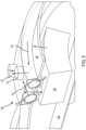
- FIG. 4 a perspective view of a heat exchanger 400 is illustrated, in accordance with various embodiments.
- the heat exchanger 104 from FIGs. 2 and 3 can be in accordance (i.e., can contain the same features), with the heat exchanger 400 as described further herein.
- the heat exchanger 400 comprises a housing 410, an inlet conduit 420, an outlet conduit 430, an inlet manifold 440, an outlet manifold 450, and a heat transfer region 460.
- a heat transfer region as referred to herein is a portion of the heat exchanger where a first fluid (e.g., air, a working fluid or the like) interacts with a second fluid (e.g., air, a working fluid or the like), to transfer heat from the first fluid to the second fluid or vice versa.
- a first fluid e.g., air, a working fluid or the like
- a second fluid e.g., air, a working fluid or the like
- the first fluid and the second fluid can be any fluid for use in a heat exchanger.
- air, water, fuel, oil, or any other fluid utilized in heat exchangers are within the scope of this disclosure.
- the inlet conduit 420 is in fluid communication with the outlet conduit 430 through the heat transfer region 460.
- a fluid conduit 425 extends through the heat transfer region 460, and sometimes out of the heat transfer region 460 from the inlet conduit 420 to the outlet conduit 430.
- the inlet manifold 440 is in fluid communication with the outlet manifold 450 through the heat transfer region 460.
- the inlet manifold 440 is defined by an interior surface 442 that extends axially from a first edge 444 disposed at a first axial end of the heat exchanger 400 to a second edge 446 defined by an inlet 462 to the heat transfer region 460.
- the outlet manifold 450 is in accordance with the inlet manifold (i.e., with an interior surface that extends axially from a first edge defined by an outlet of the heat transfer region to a second edge defined by a second axial end of the heat exchanger 400.
- the inlet conduit 420 comprises an interior surface 422 and the outlet conduit 430 comprises an interior surface 432.
- the present disclosure is not limited in this regard.
- a heat exchanger with two inlet manifolds and two outlet manifolds or a heat exchanger with two inlet conduits and two outlet conduits are within the scope of this disclosure.
- FIG. 4B a side view of a heat exchanger 401 with two inlet conduits (e.g., inlet conduit 620 and inlet conduit 621) and two outlet conduits (e.g., outlet conduit 630 and outlet conduit 631) is illustrated, in accordance with various embodiments.
- the inlet conduits 620, 621 are in accordance with the inlet conduit 420
- the outlet conduits 630, 631 are in accordance with the outlet conduit 430 from FIG. 4A .
- the heat exchanger 401 comprises inlet manifolds 640, 641 and outlet manifolds 650, 651.
- the inlet manifold 640 can be disposed between the inlet conduit 620 and the heat transfer region 660 within the heat exchanger 401.
- the inlet manifold 641 can be disposed between the inlet conduit 621 and the heat transfer region 660
- the outlet manifold 650 can be disposed between the outlet conduit 630 and the heat transfer region 660
- the outlet manifold 651 can be disposed between the outlet conduit 631.
- an outlet of the inlet conduit 620 can be the heat transfer region 660 directly and would still be within the scope of this disclosure.
- a first fluid is supplied through the inlet conduit 620 to a heat transfer region 660 and exhausted out the outlet conduit 630.
- a second fluid is supplied through the inlet conduit 621 to the heat transfer region 660 and out the outlet conduit 631.
- the first fluid is at a first temperature that is greater than the second fluid.
- the heat transfer region 660 is configured to decrease the first temperature of the first fluid and increase the temperature of the second fluid.
- an air-to-air heat exchanger may extract the first fluid that is 22 degree F above ambient in the inlet conduit 620 and extract a second fluid that is 10 degrees F below ambient from the inlet conduit 621.
- the second fluid may be heated up to approximately 15 degrees F above ambient and exhausted out the outlet conduit 631, and the first fluid may be cooled down to approximately 5 degrees above ambient and exhausted out the outlet conduit 630.
- any fluid-to-fluid heat exchanger is within the scope of this disclosure.
- various fluids and media may be circulated throughout the heat exchangers 400, 401 during operation and may carry heat including, without limitation, air, fuel, oil, lubricating fluid, hydraulic fluid, thermally neutral heat-transfer fluid, or any other fluid suitable for circulating through a heat exchanger 400, 401.
- each inlet conduit, outlet conduit, inlet manifold and outlet manifold of the heat exchanger 401 each comprise an interior surface configured to reduce a pressure less in the heat exchanger 401.
- the inlet conduit 620 comprises an interior surface 622
- the inlet conduit 621 comprises an interior surface 623
- the outlet conduit 630 comprises an interior surface 632
- the outlet conduit 631 comprises an interior surface 633
- the inlet manifold 640 comprises an interior surface 642
- the inlet manifold 641 comprises an interior surface 643
- the outlet manifold 650 comprises an interior surface 652
- the outlet manifold 651 comprises an interior surface 653.
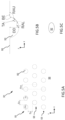
- FIGs. 5A and 5B a top view ( FIG. 5A ) and a cross-sectional view ( FIG. 5B ) of an interior surface 500 (e.g., any of interior surfaces 422, 432, 442, 622, 623, 632, 633, 642, 643, 652, 653 and/or an interior surface of outlet manifold 450 from FIGs. 4A and 4B ) is illustrated, in accordance with various embodiments.
- an interior surface 500 e.g., any of interior surfaces 422, 432, 442, 622, 623, 632, 633, 642, 643, 652, 653 and/or an interior surface of outlet manifold 450 from FIGs. 4A and 4B .
- the interior surface can be a cylindrical surface (e.g., for inlet conduit 420, 620, 621 and/or outlet conduit 430, 630, 631), a flat surface (e.g., for inlet manifold 440 or outlet manifold 450), or the like.
- a cylindrical surface e.g., for inlet conduit 420, 620, 621 and/or outlet conduit 430, 630, 631
- a flat surface e.g., for inlet manifold 440 or outlet manifold 450
- the interior surface 500 comprises a dimple configuration 501 with a plurality of dimples (e.g., dimple 502).
- each dimple e.g., dimple 502
- the dimple 502 comprises a diameter in an X-direction ("Dx") and a diameter in a Y-direction ("Dy").
- the X-direction can correspond to an axial direction (i.e., an axial direction of a fluid conduit or an axial direction of a manifold as shown in FIG.
- the Y-direction can correspond to a circumferential direction (i.e., for a fluid conduit) or a lateral direction (i.e., for a manifold defined by a flat surface).
- the dimple 502 can comprise an elliptical shape (e.g., as shown in FIG. 5C ), in accordance with various embodiments.
- diameter Dx can vary between 0.007 inches (0.018 cm) and 2.9 inches (7.366 cm)
- diameter Dy can vary between 0.007 inches (0.018 cm) and 2.9 inches (7.366 cm), in accordance with various embodiments.
- dimples 502 can be spaced apart in the X-direction ("Sx"), and the dimples 502 can be spaced apart in the Y-direction (“Sy”).
- Sy and Sx can each vary between 0.001 inches (.0025 cm) and 1.9 inches (4.83 cm).
- the present disclosure is not limited in this regard.
- the dimple configuration 501 can comprise arrays of dimples (e.g., two or more dimples 502 spaced close together (e.g., 0.001 inches (0.0025 cm) then a larger gap (e.g., 1 inch (2.54 cm)), then have the pattern repeat.
- arrays of dimples e.g., two or more dimples 502 spaced close together (e.g., 0.001 inches (0.0025 cm) then a larger gap (e.g., 1 inch (2.54 cm)), then have the pattern repeat.
- the dimple configuration 501 comprises a plurality of dimples arranged in rows (e.g., rows 510, 520, 530 as shown in FIG. 5A ).
- adjacent rows e.g., rows 510, 520
- the Rox corresponds to two times the Sx direction.
- the dimple 502 further comprise a ramp angle upper (“RAU”), a ramp angle lower (“RAL”), a transition angle (“TA”), a break angle (“BE”), and a depth of dimple (“DD”).
- the RAU is an angle between the interior surface 500, and an interior surface of the dimple 502.
- the TA is an angle from a vertical reference (i.e., a normal direction from the interior surface 500), and a tangent line between a vertex defined by the dimple 502 and the interior surface 500 and a point defined by the DD.
- the RAL is an angle between the tangent line and a horizontal plane defined by the DD.
- the break edge is an angle that transitions the interior surface 500 to an interior surface of the dimple 502.
- the dimple 502 can be a partial sphere. In various embodiments, the dimple 502 can have a depth greater than diameter Dx and diameter Dy or less than diameter Dx and Dy, the present disclosure is not limited in this regard. In various embodiments, the dimple 502 is configured to induce turbulent flow. In various embodiments, turbulent flow can result in reduced pressure loss relative to laminar flow.
- the RAU can be between 90 degrees and 179 degrees.
- the RAL can be between 0 degrees and 90 degrees.
- the TA can be between 0 degrees and 89 degrees.
- the BE can be between 181 degrees and 270 degrees.
- the DD can be between 0.001 inches (0.0025 cm) and 1.5 inches (3.81 cm).
- the interior surface 500 can be substantially an entire length of an inlet conduit (e.g., inlet conduit 420 from FIG. 4 ), an outlet conduit (e.g., outlet conduit 430), an inlet manifold (e.g., inlet manifold 440), an outlet manifold (e.g., outlet manifold 450), a supply conduit (e.g., supply conduit 114), a return conduit (e.g., return conduit 116), or the like.
- an inlet conduit e.g., inlet conduit 420 from FIG. 4
- an outlet conduit e.g., outlet conduit 430
- an inlet manifold e.g., inlet manifold 440
- an outlet manifold e.g., outlet manifold 450
- a supply conduit e.g., supply conduit 114
- return conduit e.g., return conduit 116
- substantially the entire length as referred to herein is between 95% and 100% of a total length as measured from a first end of a conduit (or manifold) to a second end of a conduit (or manifold), the second end being proximate (or adjacent) the heat transfer region 460 of a heat exchanger 400 from FIG. 4 , in accordance with various embodiments.
- a pressure loss of a fluid entering and exiting a heat exchanger can be reduced, thereby increasing an efficiency of the heat exchanger (e.g., heat exchanger 104 or heat exchanger 400).
- references to "one embodiment”, “an embodiment”, “an example embodiment”, etc. indicate that the embodiment described may include a particular feature, structure, or characteristic, but every embodiment may not necessarily include the particular feature, structure, or characteristic. Moreover, such phrases are not necessarily referring to the same embodiment. Further, when a particular feature, structure, or characteristic is described in connection with an embodiment, it is submitted that it is within the knowledge of one skilled in the art to affect such feature, structure, or characteristic in connection with other embodiments whether or not explicitly described. After reading the description, it will be apparent to one skilled in the relevant art(s) how to implement the disclosure in alternative embodiments.
Landscapes
- Engineering & Computer Science (AREA)
- Mechanical Engineering (AREA)
- General Engineering & Computer Science (AREA)
- Physics & Mathematics (AREA)
- Thermal Sciences (AREA)
- Chemical & Material Sciences (AREA)
- Combustion & Propulsion (AREA)
- Heat-Exchange Devices With Radiators And Conduit Assemblies (AREA)
Abstract
A heat exchanger (104, 400) can comprise: a housing (401); a heat transfer region (460) disposed within the housing; and an inlet manifold (440) or an inlet conduit (420) defined at least partially by an interior surface (422) extending axially from a first end of the heat exchanger to an inlet (462) defined by the heat transfer region, the inlet manifold or the inlet conduit comprising a dimple configuration (501) disposed in the interior surface. The heat exchanger can further comprise an outlet manifold (450) or an outlet conduit (430) including a dimple configuration disposed on an interior surface (432) of the outlet manifold or outlet conduit.
Description
- The present disclosure relates to heat exchangers, and, more specifically, to heat exchanger systems and devices for reduced pressure loss.
- A gas turbine engine typically includes a fan section, a compressor section, a combustor section, and a turbine section. In general, during operation, air is pressurized in the fan and compressor sections, and is mixed with fuel, and burned in the combustor section to generate hot combustion gases. The hot combustion gases flow through the turbine section, which extracts energy from the hot combustion gases to power the compressor section and other gas turbine engine loads.
- Gas turbine engines may include various cooling systems that employ heat exchangers. Bypass air may be directed across the heat exchangers as a cooling fluid. The inlet piping, or outlet piping of the heat exchanger (i.e., the bypass air exiting the heat exchanger) may cause pressure loss that may otherwise be used to drive heat rejection in the heat exchanger. A significant loss in pressure at inlets and outlets of heat exchangers can greatly reduce a heat exchanger performance.
- A heat exchanger is disclosed herein. In various embodiments, the heat exchanger comprises a housing; a heat transfer region disposed within the housing; and an inlet manifold defined at least partially by an interior surface extending axially from a first end of the heat exchanger to an inlet defined by the heat transfer region, the inlet manifold comprising a dimple configuration disposed in the interior surface.
- In various embodiments, the dimple configuration comprises a plurality of dimples spaced apart axially along the interior surface. The dimple configuration can further comprise rows of the plurality of dimples spaced apart laterally along the interior surface.
- In various embodiments, each dimple in the plurality of dimples comprises a first diameter in a X-direction, a second diameter in a Y-direction, and a depth of dimple, the depth of dimple measured from the interior surface to a max depth of the dimple.
- In various embodiments, the heat exchanger further comprises an outlet manifold in fluid communication with the inlet manifold through the heat transfer region, the outlet manifold comprising the dimple configuration. In various embodiments, the heat exchanger further comprises an inlet fluid conduit and an outlet fluid conduit, the inlet fluid conduit in fluid communication with the outlet fluid conduit through the heat transfer region. In various embodiments, the inlet fluid conduit and the outlet fluid conduit each comprise the heat transfer region.
- A heat exchanger is disclosed herein. In various embodiments, the heat exchanger comprises a housing; a heat transfer region disposed within the housing; and an inlet fluid conduit extending from a first end to an inlet of the housing, the inlet defined by the heat transfer region, the inlet fluid conduit defining an interior surface and comprising a dimple configuration disposed in the interior surface.
- In various embodiments, the interior surface is a cylindrical surface. In various embodiments, the dimple configuration comprises a plurality of dimples spaced apart axially along the interior surface. In various embodiments, the dimple configuration comprises rows of the plurality of dimples spaced apart circumferentially along the cylindrical surface. In various embodiments, each dimple in the plurality of dimples comprises a first diameter in a X-direction, a second diameter in a Y-direction, and a depth of dimple, the depth of dimple measured from the interior surface to a max depth of the dimple.
- In various embodiments, the heat exchanger further comprises an outlet fluid conduit in fluid communication with the inlet fluid conduit through a fluid conduit in the heat transfer region, the outlet fluid conduit comprising the dimple configuration. In various embodiments, the fluid conduit in the heat transfer region is without dimples.
- In various embodiments, the heat exchanger further comprises an inlet manifold and an outlet manifold, the inlet manifold in fluid communication with the outlet manifold through the heat transfer region.
- A gas turbine engine is disclosed herein. In various embodiments, the gas turbine engine comprises: a heat exchanger comprising a heat transfer region; an inlet manifold and an outlet manifold; the outlet manifold in fluid communication with the inlet manifold through the heat transfer region; a supply conduit; and a return conduit in fluid communication with the supply conduit through the heat transfer region of the heat exchanger, wherein an interior surface of at least one of the supply conduit, the return conduit, the inlet manifold and the outlet manifold comprises a dimple configuration.
- The foregoing features and elements may be combined in various combinations without exclusivity, unless expressly indicated otherwise. These features and elements as well as the operation thereof will become more apparent in light of the following description and the accompanying drawings. It should be understood, however, the following description and drawings are intended to be exemplary in nature and non-limiting.
- The subject matter of the present disclosure is particularly pointed out and distinctly claimed in the concluding portion of the specification. A more complete understanding of the present disclosure, however, may best be obtained by referring to the detailed description and claims when considered in connection with the figures, wherein like numerals denote like elements.
-
FIG. 1 illustrates a cross-sectional view of an exemplary gas turbine engine, in accordance with various embodiments; -
FIG. 2 illustrates a perspective view of a cooling system having a plenum, in accordance with various embodiments; -
FIG. 3 illustrates a perspective view of a cooling system having a plenum, in accordance with various embodiments; -
FIG. 4A illustrates a perspective view of a heat exchanger, in accordance with various embodiments; -
FIG. 4B illustrates a side view of a heat exchanger, in accordance with various embodiments; -
FIG. 5A illustrates a top view of an interior surface with a dimple configuration, in accordance with various embodiments; and -
FIG. 5B illustrates a cross-sectional view of the interior surface with a dimple of the dimple configuration, in accordance with various embodiments. -
FIG. 5C illustrates an elliptical view of the interior surface with a dimple of the dimple configuration, in accordance with various embodiments. - The detailed description of exemplary embodiments herein makes reference to the accompanying drawings, which show exemplary embodiments by way of illustration. While these exemplary embodiments are described in sufficient detail to enable those skilled in the art to practice the exemplary embodiments of the disclosure, it should be understood that other embodiments may be realized and that logical changes and adaptations in design and construction may be made in accordance with this disclosure and the teachings herein. Thus, the detailed description herein is presented for purposes of illustration only and not limitation. The steps recited in any of the method or process descriptions may be executed in any order and are not necessarily limited to the order presented.
- Furthermore, any reference to singular includes plural embodiments, and any reference to more than one component or step may include a singular embodiment or step. Also, any reference to attached, fixed, connected or the like may include permanent, removable, temporary, partial, full and/or any other possible attachment option. Additionally, any reference to without contact (or similar phrases) may also include reduced contact or minimal contact. Surface cross hatching lines may be used throughout the figures to denote different parts, but not necessarily to denote the same or different materials.
- Throughout the present disclosure, like reference numbers denote like elements. Accordingly, elements with like element numbering may be shown in the figures, but may not necessarily be repeated herein for the sake of clarity.
- As used herein, "aft" refers to the direction associated with the tail (e.g., the back end) of an aircraft, or generally, to the direction of exhaust of a gas turbine engine.
- A first component that is "radially outward" of a second component means that the first component is positioned at a greater distance away from a central longitudinal axis of the gas turbine engine. A first component that is "radially inward" of a second component means that the first component is positioned closer to the engine central longitudinal axis than the second component. The terminology "radially outward" and "radially inward" may also be used relative to reference axes other than the engine central longitudinal axis.
- Disclosed herein are systems and apparatuses for improving a heat exchanger performance. Although disclosed herein with reference to gas turbine engines, the present disclosure is not limited in this regard. For example, any heat exchanger used in any type of application is within the scope of this disclosure. In various embodiments, an interior surface of an inlet manifold and/or an outlet manifold for a heat exchanger comprises a dimpled configuration. In various embodiments, the inlet manifold and/or the outlet manifold can be integral with the heat exchanger. In various embodiments, the inlet manifold and/or the outlet manifold can be configured to be coupled to the heat exchanger. The present disclosure is not limited in this regard. In various embodiments, the dimpled configuration may result in less separation of a boundary layer against the interior surface. In this regard, the dimpled configuration can reduce a pressure loss at an inlet and/or an outlet of a heat exchanger, resulting in improved performance of the heat exchanger, in accordance with various embodiments.
- In various embodiments and with reference to
FIG. 1 , agas turbine engine 20 is provided.Gas turbine engine 20 may generally include afan section 22, acompressor section 24, acombustor section 26, and aturbine section 28. In operation,fan section 22 drives fluid (e.g., air) along a bypass flow-path B, whilecompressor section 24 drives fluid along a core flow-path C for compression and communication intocombustor section 26 and then expansion throughturbine section 28. Althoughgas turbine engine 20 is depicted as a turbofan gas turbine engine herein, it should be understood that the concepts described herein are not limited to use with turbofans as the teachings may be applied to other types of turbine engines. -
Gas turbine engine 20 may generally comprise alow speed spool 30 and ahigh speed spool 32 mounted concentrically, via bearingsystems 38, for rotation about for rotation about engine central longitudinal axis A-A' and relative to an enginestatic structure 36. It should be understood that various bearingsystems 38 at various locations may alternatively or additionally be provided, including for example, bearingsystem 38, bearing system 38-1, and bearing system 38-2. Engine central longitudinal axis A-A' is oriented in the z direction on the provided xyz axes. The z direction on the provided xyz axes refers to the axial direction. As used herein, the term "radially" refer to directions towards and away from engine central longitudinal axis A-A' and the z-axis. As used herein, the terms "circumferential" and "circumferentially" refer to directions about central longitudinal axis A-A' and the z-axis. -
Low speed spool 30 may generally comprise aninner shaft 40 that interconnects afan 42, a low-pressure compressor 44, and a low-pressure turbine 46.Inner shaft 40 may be connected to fan 42 through a gearedarchitecture 48 that can drivefan 42 at a lower speed thanlow speed spool 30.Geared architecture 48 may comprise agear assembly 60 enclosed within agear housing 62.Gear assembly 60 couplesinner shaft 40 to a rotating fan structure.High speed spool 32 may comprise anouter shaft 50 that interconnects a high-pressure compressor 52 and high-pressure turbine 54. Acombustor 56 may be located betweenhigh pressure compressor 52 and high-pressure turbine 54. Amid-turbine frame 57 of enginestatic structure 36 may be located generally betweenhigh pressure turbine 54 and low-pressure turbine 46.Mid-turbine frame 57 may support one ormore bearing systems 38 inturbine section 28.Inner shaft 40 andouter shaft 50 may be concentric and rotate via bearingsystems 38 about engine central longitudinal axis A-A', which is collinear with their longitudinal axes. As used herein, a "high pressure" compressor or turbine experiences a higher pressure than a corresponding "low pressure" compressor or turbine. The airflow in core flow-path C may be compressed bylow pressure compressor 44 and high-pressure compressor 52, mixed and burned with fuel incombustor 56, then expanded over high-pressure turbine 54 and low-pressure turbine 46.Turbines low speed spool 30 and high-speed spool 32 in response to the expansion. - The
compressor section 24, thecombustor section 26, and theturbine section 28 are generally referred to as the engine core. Air is drawn intogas turbine engine 20 throughfan 42.Air exiting fan 42 may be divided between core flow-path C and bypass flow-path B. The airflow in bypass flow-path B may be utilized for multiple purposes including, for example, cooling and pressurization. - Referring to
FIG. 2 , and with continued reference toFIG. 1 , acooling system 100 having aheat exchanger 104 is illustrated, in accordance with various embodiments. Theheat exchanger 104 may be located between an outerengine case structure 106 and an innerengine case structure 108. Outerengine case structure 106 is radially outward of innerengine case structure 108. Outerengine case structure 106 and innerengine case structure 108 may define a generallyannular bypass duct 102 around the engine core. In various embodiments, innerengine case structure 108 may form a portion of enginestatic structure 36. In various embodiments, air discharged from, for example,fan section 22 may be communicated through thebypass duct 102. - In various embodiments, the
cooling system 100 comprise asupply conduit 114 and areturn conduit 116. In accordance with various embodiments, aninlet conduit 112 may be fluidly coupled between an external source from an aircraftproximate engine bay 130 and asupply conduit 114.Engine bay 130 may be disposed radially outward from outerengine case structure 106.Supply conduit 114 may extend circumferentially about outerengine case structure 106 and/or form an annular tube. The external source from the aircraft may be disposed radially outward of outerengine case structure 106.Inlet conduit 112 directs hot air (i.e., air to be cooled) toheat exchanger 104.Inlet conduit 112 is fluidly coupled to aninlet conduit 115 ofheat exchanger 104.Supply conduit 114 may be fluidly coupled to eachheat exchanger 104 by theinlet conduit 115 extending radially inward fromsupply conduit 114 through outerengine case structure 106. - In accordance with various embodiments, an
outlet conduit 118 may be fluidly coupled between an external destination from an aircraftproximate engine bay 130 and returnconduit 116. Returnconduit 116 may extend circumferentially about outerengine case structure 106 and/or form an annular tube. The external destination from the aircraft may be disposed radially outward of outerengine case structure 106.Outlet conduit 118 directs cool air (i.e., air that is cooled by heat exchanger 104) to the external destination.Outlet conduit 118 is fluidly coupled to anoutlet conduit 117 ofheat exchanger 104. Returnconduit 116 may be fluidly coupled to eachheat exchanger 104 by theoutlet conduit 117 extending radially inward fromreturn conduit 116 through outerengine case structure 106. - The hot air provided by
inlet conduit 112 is cooled inheat exchanger 104 and then returned to the external source from the aircraft through areturn conduit 116. Returnconduit 116 is fluidly coupled to anoutlet conduit 117 ofheat exchanger 104 andoutlet conduit 118. The cooled air inreturn conduit 116 may be directed downstream to cool components in thermally challenged regions. -
Heat exchanger 104 is configured to receive a cooling airflow, for example,airflow 124. In various embodiments,airflow 124 may be a portion of the bypass airflow inbypass duct 102.Cooling airflow 124 may be directed through aninlet manifold 126 acrossheat exchanger 104 and out anoutlet manifold 129 to cool the air supplied frominlet conduit 115 inheat exchanger 104. - Referring to
FIG. 3 , acooling system 100 having aheat exchanger 104 is illustrated, in accordance with various embodiments. In various embodiments,inlet conduit 112 may be integral to supplyconduit 114. Similarly,outlet conduit 118 may be integral to returnconduit 116. "Integral," as referred to herein is a monolithic component. In various embodiments, hot air may flow throughsupply conduit 114 in a firstcircumferential direction 142 and the return cooler air may flow thoughreturn conduit 116 in a secondcircumferential direction 144. The firstcircumferential direction 142 and the secondcircumferential direction 144 may be opposite directions. - Referring now to
FIG. 4 , a perspective view of aheat exchanger 400 is illustrated, in accordance with various embodiments. In various embodiments, theheat exchanger 104 fromFIGs. 2 and3 can be in accordance (i.e., can contain the same features), with theheat exchanger 400 as described further herein. In various embodiments, theheat exchanger 400 comprises ahousing 410, aninlet conduit 420, anoutlet conduit 430, aninlet manifold 440, anoutlet manifold 450, and aheat transfer region 460. "A heat transfer region" as referred to herein is a portion of the heat exchanger where a first fluid (e.g., air, a working fluid or the like) interacts with a second fluid (e.g., air, a working fluid or the like), to transfer heat from the first fluid to the second fluid or vice versa. In various embodiments, the first fluid and the second fluid can be any fluid for use in a heat exchanger. For example, air, water, fuel, oil, or any other fluid utilized in heat exchangers are within the scope of this disclosure. - In various embodiments, the
inlet conduit 420 is in fluid communication with theoutlet conduit 430 through theheat transfer region 460. For example, afluid conduit 425 extends through theheat transfer region 460, and sometimes out of theheat transfer region 460 from theinlet conduit 420 to theoutlet conduit 430. Similarly, theinlet manifold 440 is in fluid communication with theoutlet manifold 450 through theheat transfer region 460. - In various embodiments, the
inlet manifold 440 is defined by aninterior surface 442 that extends axially from afirst edge 444 disposed at a first axial end of theheat exchanger 400 to asecond edge 446 defined by aninlet 462 to theheat transfer region 460. Similarly, in accordance with various embodiments, theoutlet manifold 450 is in accordance with the inlet manifold (i.e., with an interior surface that extends axially from a first edge defined by an outlet of the heat transfer region to a second edge defined by a second axial end of theheat exchanger 400. - In various embodiments, the
inlet conduit 420 comprises aninterior surface 422 and theoutlet conduit 430 comprises aninterior surface 432. Although described herein as having aninlet manifold 440 and anoutlet manifold 450 with aninlet conduit 420 and anoutlet conduit 430, the present disclosure is not limited in this regard. For example, a heat exchanger with two inlet manifolds and two outlet manifolds or a heat exchanger with two inlet conduits and two outlet conduits (e.g.,FIG. 4B ) are within the scope of this disclosure. - Referring now to
FIG. 4B , a side view of aheat exchanger 401 with two inlet conduits (e.g.,inlet conduit 620 and inlet conduit 621) and two outlet conduits (e.g.,outlet conduit 630 and outlet conduit 631) is illustrated, in accordance with various embodiments. In various embodiments, theinlet conduits inlet conduit 420, and theoutlet conduits outlet conduit 430 fromFIG. 4A . - In various embodiments, the
heat exchanger 401 comprisesinlet manifolds inlet manifold 640 can be disposed between theinlet conduit 620 and theheat transfer region 660 within theheat exchanger 401. Similarly, theinlet manifold 641 can be disposed between theinlet conduit 621 and theheat transfer region 660, theoutlet manifold 650 can be disposed between theoutlet conduit 630 and theheat transfer region 660, and theoutlet manifold 651 can be disposed between theoutlet conduit 631. However, the present disclosure is not limited in this regard. For example, an outlet of theinlet conduit 620 can be theheat transfer region 660 directly and would still be within the scope of this disclosure. - In various embodiments, a first fluid is supplied through the
inlet conduit 620 to aheat transfer region 660 and exhausted out theoutlet conduit 630. Similarly, a second fluid is supplied through theinlet conduit 621 to theheat transfer region 660 and out theoutlet conduit 631. In various embodiments, the first fluid is at a first temperature that is greater than the second fluid. In this regard, theheat transfer region 660 is configured to decrease the first temperature of the first fluid and increase the temperature of the second fluid. For example, in accordance with various embodiments, an air-to-air heat exchanger may extract the first fluid that is 22 degree F above ambient in theinlet conduit 620 and extract a second fluid that is 10 degrees F below ambient from theinlet conduit 621. As a result, in accordance with various embodiments, the second fluid may be heated up to approximately 15 degrees F above ambient and exhausted out theoutlet conduit 631, and the first fluid may be cooled down to approximately 5 degrees above ambient and exhausted out theoutlet conduit 630. - Although described with respect to an air-to-air heat exchanger, the present disclosure is not limited in this regard. Any fluid-to-fluid heat exchanger is within the scope of this disclosure. For example, various fluids and media may be circulated throughout the
heat exchangers heat exchanger - In various embodiments, each inlet conduit, outlet conduit, inlet manifold and outlet manifold of the
heat exchanger 401 each comprise an interior surface configured to reduce a pressure less in theheat exchanger 401. For example, theinlet conduit 620 comprises aninterior surface 622, theinlet conduit 621 comprises aninterior surface 623, theoutlet conduit 630 comprises aninterior surface 632, theoutlet conduit 631 comprises aninterior surface 633, theinlet manifold 640 comprises aninterior surface 642, theinlet manifold 641 comprises aninterior surface 643, theoutlet manifold 650 comprises aninterior surface 652, and theoutlet manifold 651 comprises aninterior surface 653. - Referring now to
FIGs. 5A and 5B , a top view (FIG. 5A ) and a cross-sectional view (FIG. 5B ) of an interior surface 500 (e.g., any ofinterior surfaces outlet manifold 450 fromFIGs. 4A and4B ) is illustrated, in accordance with various embodiments. In various embodiments, the interior surface can be a cylindrical surface (e.g., forinlet conduit outlet conduit inlet manifold 440 or outlet manifold 450), or the like. The present disclosure is not limited in this regard. - In various embodiments, the
interior surface 500 comprises adimple configuration 501 with a plurality of dimples (e.g., dimple 502). In various embodiments, each dimple (e.g., dimple 502) can be the same for ease of manufacturing. However, the present disclosure is not limited in this regard, and varying dimple sizes (i.e., diameter and depth) throughout thedimple configuration 501 is within the scope of this disclosure. In various embodiments, thedimple 502 comprises a diameter in an X-direction ("Dx") and a diameter in a Y-direction ("Dy"). The X-direction can correspond to an axial direction (i.e., an axial direction of a fluid conduit or an axial direction of a manifold as shown inFIG. 4 ), and the Y-direction can correspond to a circumferential direction (i.e., for a fluid conduit) or a lateral direction (i.e., for a manifold defined by a flat surface). From a top view (FIG. 5A ), thedimple 502 can comprise an elliptical shape (e.g., as shown inFIG. 5C ), in accordance with various embodiments. Although thedimple 502 is illustrated as a circular cross-section in an XY plane, the present disclosure is not limited in this regard. For example, diameter Dx can vary between 0.007 inches (0.018 cm) and 2.9 inches (7.366 cm), and diameter Dy can vary between 0.007 inches (0.018 cm) and 2.9 inches (7.366 cm), in accordance with various embodiments. - In various embodiments,
dimples 502 can be spaced apart in the X-direction ("Sx"), and thedimples 502 can be spaced apart in the Y-direction ("Sy"). For example, Sy and Sx can each vary between 0.001 inches (.0025 cm) and 1.9 inches (4.83 cm). Although illustrated as being spaced apart equally in the x-direction and spaced apart equally in the y-direction, the present disclosure is not limited in this regard. For example, thedimple configuration 501 can comprise arrays of dimples (e.g., two ormore dimples 502 spaced close together (e.g., 0.001 inches (0.0025 cm) then a larger gap (e.g., 1 inch (2.54 cm)), then have the pattern repeat. - In various embodiments, the
dimple configuration 501 comprises a plurality of dimples arranged in rows (e.g.,rows FIG. 5A ). In various embodiments, adjacent rows (e.g., rows 510, 520) can be offset in an X direction ("Rox"). In various embodiments, the Rox corresponds to two times the Sx direction. - Referring now to
FIG. 5B , a cross-sectional view of adimple 502 fromFIG. 5A is illustrated, in accordance with various embodiments. In various embodiments, thedimple 502 further comprise a ramp angle upper ("RAU"), a ramp angle lower ("RAL"), a transition angle ("TA"), a break angle ("BE"), and a depth of dimple ("DD"). The RAU is an angle between theinterior surface 500, and an interior surface of thedimple 502. The TA is an angle from a vertical reference (i.e., a normal direction from the interior surface 500), and a tangent line between a vertex defined by thedimple 502 and theinterior surface 500 and a point defined by the DD. The RAL is an angle between the tangent line and a horizontal plane defined by the DD. The break edge is an angle that transitions theinterior surface 500 to an interior surface of thedimple 502. - In various embodiments, the
dimple 502 can be a partial sphere. In various embodiments, thedimple 502 can have a depth greater than diameter Dx and diameter Dy or less than diameter Dx and Dy, the present disclosure is not limited in this regard. In various embodiments, thedimple 502 is configured to induce turbulent flow. In various embodiments, turbulent flow can result in reduced pressure loss relative to laminar flow. - In various embodiments, the RAU can be between 90 degrees and 179 degrees. In various embodiments, the RAL can be between 0 degrees and 90 degrees. In various embodiments, the TA can be between 0 degrees and 89 degrees. In various embodiments, the BE can be between 181 degrees and 270 degrees. In various embodiments, the DD can be between 0.001 inches (0.0025 cm) and 1.5 inches (3.81 cm).
- In various embodiments, the
interior surface 500 can be substantially an entire length of an inlet conduit (e.g.,inlet conduit 420 fromFIG. 4 ), an outlet conduit (e.g., outlet conduit 430), an inlet manifold (e.g., inlet manifold 440), an outlet manifold (e.g., outlet manifold 450), a supply conduit (e.g., supply conduit 114), a return conduit (e.g., return conduit 116), or the like. The present disclosure is not limited in this regard. In various embodiments, "substantially the entire length" as referred to herein is between 95% and 100% of a total length as measured from a first end of a conduit (or manifold) to a second end of a conduit (or manifold), the second end being proximate (or adjacent) theheat transfer region 460 of aheat exchanger 400 fromFIG. 4 , in accordance with various embodiments. - In various embodiments, by having a
dimple configuration 501 as disclosed herein, a pressure loss of a fluid entering and exiting a heat exchanger can be reduced, thereby increasing an efficiency of the heat exchanger (e.g.,heat exchanger 104 or heat exchanger 400). - Benefits, other advantages, and solutions to problems have been described herein with regard to specific embodiments. Furthermore, the connecting lines shown in the various figures contained herein are intended to represent exemplary functional relationships and/or physical couplings between the various elements. It should be noted that many alternative or additional functional relationships or physical connections may be present in a practical system. However, the benefits, advantages, solutions to problems, and any elements that may cause any benefit, advantage, or solution to occur or become more pronounced are not to be construed as critical, required, or essential features or elements of the disclosures. The scope of the disclosures is accordingly to be limited by nothing other than the appended claims, in which reference to an element in the singular is not intended to mean "one and only one" unless explicitly so stated, but rather "one or more." Moreover, where a phrase similar to "at least one of A, B, or C" is used in the claims, it is intended that the phrase be interpreted to mean that A alone may be present in an embodiment, B alone may be present in an embodiment, C alone may be present in an embodiment, or that any combination of the elements A, B and C may be present in a single embodiment; for example, A and B, A and C, B and C, or A and B and C. Different cross-hatching is used throughout the figures to denote different parts but not necessarily to denote the same or different materials.
- Systems, methods and apparatus are provided herein. In the detailed description herein, references to "one embodiment", "an embodiment", "an example embodiment", etc., indicate that the embodiment described may include a particular feature, structure, or characteristic, but every embodiment may not necessarily include the particular feature, structure, or characteristic. Moreover, such phrases are not necessarily referring to the same embodiment. Further, when a particular feature, structure, or characteristic is described in connection with an embodiment, it is submitted that it is within the knowledge of one skilled in the art to affect such feature, structure, or characteristic in connection with other embodiments whether or not explicitly described. After reading the description, it will be apparent to one skilled in the relevant art(s) how to implement the disclosure in alternative embodiments.
- Furthermore, no element, component, or method step in the present disclosure is intended to be dedicated to the public regardless of whether the element, component, or method step is explicitly recited in the claims. No claim element is intended to invoke 35 U.S.C. 112(f) unless the element is expressly recited using the phrase "means for." As used herein, the terms "comprises", "comprising", or any other variation thereof, are intended to cover a non-exclusive inclusion, such that a process, method, article, or apparatus that comprises a list of elements does not include only those elements but may include other elements not expressly listed or inherent to such process, method, article, or apparatus.
Claims (15)
- A heat exchanger, comprising:a housing;a heat transfer region disposed within the housing; andan inlet manifold defined at least partially by an interior surface extending axially from a first end of the heat exchanger to an inlet defined by the heat transfer region, the inlet manifold comprising a dimple configuration disposed in the interior surface.
- The heat exchanger of claim 1, further comprising:an outlet manifold in fluid communication with the inlet manifold through the heat transfer region, the outlet manifold comprising the dimple configuration; andan inlet fluid conduit and an outlet fluid conduit, the inlet fluid conduit in fluid communication with the outlet fluid conduit through the heat transfer region.
- The heat exchanger of claim 2, wherein the inlet fluid conduit and the outlet fluid conduit each comprise the heat transfer region.
- A heat exchanger, comprising:a housing;a heat transfer region disposed within the housing; andan inlet fluid conduit extending from a first end to an inlet of the housing, the inlet defined by the heat transfer region, the inlet fluid conduit defining an interior surface and comprising a dimple configuration disposed in the interior surface.
- The heat exchanger of claim 4, wherein the interior surface is a cylindrical surface.
- The heat exchanger of claim 5, wherein the dimple configuration comprises a plurality of dimples spaced apart axially along the interior surface.
- The heat exchanger of claim 6, wherein the dimple configuration comprises rows of the plurality of dimples spaced apart circumferentially along the cylindrical surface.
- The heat exchanger of any of claims 4 to 7, further comprising an outlet fluid conduit in fluid communication with the inlet fluid conduit through a fluid conduit in the heat transfer region, the outlet fluid conduit comprising the dimple configuration, wherein the fluid conduit in the heat transfer region is without dimples.
- The heat exchanger of any of claims 4 to 8, further comprising an inlet manifold and an outlet manifold, the inlet manifold in fluid communication with the outlet manifold through the heat transfer region.
- A gas turbine engine, comprising:a heat exchanger comprising a heat transfer region, an inlet manifold and an outlet manifold, the outlet manifold in fluid communication with the inlet manifold through the heat transfer region;a supply conduit; anda return conduit in fluid communication with the supply conduit through the heat transfer region of the heat exchanger, wherein an interior surface of at least one of the supply conduit, the return conduit, the inlet manifold and the outlet manifold comprises a dimple configuration.
- The heat exchanger of any of claims 1, 2 or 3, or the gas turbine engine of claim 10, wherein the dimple configuration comprises a plurality of dimples spaced apart axially along the interior surface.
- The heat exchanger of claim 11, wherein the dimple configuration comprises rows of the plurality of dimples spaced apart laterally along the interior surface.
- The heat exchanger of claim 6, 7, 11 or 12, or the gas turbine engine of claim 11, wherein each dimple in the plurality of dimples comprises a first diameter in a X-direction, a second diameter in a Y-direction, and a depth of dimple, the depth of dimple measured from the interior surface to a max depth of the dimple.
- The heat exchanger of claim 13, wherein the first diameter in the X-direction and the second diameter in the Y-direction are each between 0.007 inches (0.18 cm) and 2.9 inches (7.4 cm), and the depth of dimple is between 0.001 inches (0.0025 cm) and 1.5 inches (3.81 cm).
- The gas turbine engine of any of claims 10, 11 or 13, wherein the heat exchanger is configured to receive a first fluid from the inlet manifold and a second fluid from the supply conduit, wherein, optionally, heat is transferred from the first fluid to the second fluid in the heat transfer region.
Applications Claiming Priority (1)
| Application Number | Priority Date | Filing Date | Title |
|---|---|---|---|
| US18/153,936 US12405071B2 (en) | 2023-01-12 | 2023-01-12 | Heat exchanger systems and devices for reduced pressure loss |
Publications (1)
| Publication Number | Publication Date |
|---|---|
| EP4400701A1 true EP4400701A1 (en) | 2024-07-17 |
Family
ID=89073194
Family Applications (1)
| Application Number | Title | Priority Date | Filing Date |
|---|---|---|---|
| EP23213817.2A Pending EP4400701A1 (en) | 2023-01-12 | 2023-12-01 | Heat exchanger systems and devices for reduced pressure loss |
Country Status (2)
| Country | Link |
|---|---|
| US (1) | US12405071B2 (en) |
| EP (1) | EP4400701A1 (en) |
Citations (6)
| Publication number | Priority date | Publication date | Assignee | Title |
|---|---|---|---|---|
| JP2007073192A (en) * | 2005-09-02 | 2007-03-22 | Toyota Motor Corp | FUEL CELL AND FUEL CELL SYSTEM INCLUDING THE SAME |
| US20120017605A1 (en) * | 2010-07-23 | 2012-01-26 | University Of Central Florida Research Foundation, Inc. | Heat transfer augmented fluid flow surfaces |
| US20160359211A1 (en) * | 2015-06-04 | 2016-12-08 | Dana Canada Corporation | Heat Exchanger with Regional Flow Distribution for Uniform Cooling of Battery Cells |
| CA2964617A1 (en) * | 2016-05-02 | 2017-11-02 | General Electric Company | Dimpled nacelle inner-surface for heat transfer improvement |
| CA2976534A1 (en) * | 2016-08-31 | 2018-02-28 | Unison Industries, Llc | Engine heat exchanger and method of forming |
| RU2707237C2 (en) * | 2015-03-26 | 2019-11-25 | Касале Са | Plate-type heat exchanger for chemical reactors with automatically welded headers |
Family Cites Families (3)
| Publication number | Priority date | Publication date | Assignee | Title |
|---|---|---|---|---|
| US20150285569A1 (en) | 2014-04-04 | 2015-10-08 | Delphi Technologies, Inc. | Heat exchanger with dimpled manifold |
| US10821509B2 (en) | 2016-01-20 | 2020-11-03 | General Electric Company | Additive heat exchanger mixing chambers |
| CN111509325A (en) * | 2019-01-30 | 2020-08-07 | 达纳加拿大公司 | Heat exchanger with multi-channel fluid flow passages |
-
2023
- 2023-01-12 US US18/153,936 patent/US12405071B2/en active Active
- 2023-12-01 EP EP23213817.2A patent/EP4400701A1/en active Pending
Patent Citations (6)
| Publication number | Priority date | Publication date | Assignee | Title |
|---|---|---|---|---|
| JP2007073192A (en) * | 2005-09-02 | 2007-03-22 | Toyota Motor Corp | FUEL CELL AND FUEL CELL SYSTEM INCLUDING THE SAME |
| US20120017605A1 (en) * | 2010-07-23 | 2012-01-26 | University Of Central Florida Research Foundation, Inc. | Heat transfer augmented fluid flow surfaces |
| RU2707237C2 (en) * | 2015-03-26 | 2019-11-25 | Касале Са | Plate-type heat exchanger for chemical reactors with automatically welded headers |
| US20160359211A1 (en) * | 2015-06-04 | 2016-12-08 | Dana Canada Corporation | Heat Exchanger with Regional Flow Distribution for Uniform Cooling of Battery Cells |
| CA2964617A1 (en) * | 2016-05-02 | 2017-11-02 | General Electric Company | Dimpled nacelle inner-surface for heat transfer improvement |
| CA2976534A1 (en) * | 2016-08-31 | 2018-02-28 | Unison Industries, Llc | Engine heat exchanger and method of forming |
Also Published As
| Publication number | Publication date |
|---|---|
| US20240240879A1 (en) | 2024-07-18 |
| US12405071B2 (en) | 2025-09-02 |
Similar Documents
| Publication | Publication Date | Title |
|---|---|---|
| US10443436B2 (en) | Modular annular heat exchanger | |
| US8763363B2 (en) | Method and system for cooling fluid in a turbine engine | |
| US11492973B2 (en) | Folded heat exchanger for cooled cooling air | |
| EP3165740B1 (en) | Internally cooled spoke | |
| US12044171B1 (en) | Engine with intercooler | |
| US11988147B2 (en) | Heat exchanger for a hydrogen fuel delivery system | |
| US11371786B2 (en) | Heat exchanger for a gas turbine engine | |
| US12169102B2 (en) | Plumbing with internal flow guides | |
| CN118881476A (en) | Rotatable heat exchanger for gas turbine engine | |
| US10738634B2 (en) | Contact coupled singlets | |
| EP4400701A1 (en) | Heat exchanger systems and devices for reduced pressure loss | |
| EP3792478B1 (en) | A cooling system comprising an exhaust distribution manifold | |
| EP4462058A1 (en) | Heat exchanger systems and devices for increased durability | |
| US11519368B2 (en) | Heat exchanger supply plenum | |
| EP4491851A1 (en) | Gas turbine conduit with heat transfer protrusions on the surface structure | |
| US12416263B2 (en) | Rotatable heat exchanger for a gas turbine engine | |
| US12259194B2 (en) | Thermal management system | |
| US20250035382A1 (en) | Thermal management system | |
| EP3312383B1 (en) | Air mixing systems having mixing chambers for gas turbine engines | |
| EP3901411A1 (en) | Intercooled tangential air injector for gas turbine engines |
Legal Events
| Date | Code | Title | Description |
|---|---|---|---|
| PUAI | Public reference made under article 153(3) epc to a published international application that has entered the european phase |
Free format text: ORIGINAL CODE: 0009012 |
|
| STAA | Information on the status of an ep patent application or granted ep patent |
Free format text: STATUS: THE APPLICATION HAS BEEN PUBLISHED |
|
| AK | Designated contracting states |
Kind code of ref document: A1 Designated state(s): AL AT BE BG CH CY CZ DE DK EE ES FI FR GB GR HR HU IE IS IT LI LT LU LV MC ME MK MT NL NO PL PT RO RS SE SI SK SM TR |
|
| STAA | Information on the status of an ep patent application or granted ep patent |
Free format text: STATUS: REQUEST FOR EXAMINATION WAS MADE |
|
| 17P | Request for examination filed |
Effective date: 20250117 |