EP4400694A1 - Blisk - Google Patents
Blisk Download PDFInfo
- Publication number
- EP4400694A1 EP4400694A1 EP23216827.8A EP23216827A EP4400694A1 EP 4400694 A1 EP4400694 A1 EP 4400694A1 EP 23216827 A EP23216827 A EP 23216827A EP 4400694 A1 EP4400694 A1 EP 4400694A1
- Authority
- EP
- European Patent Office
- Prior art keywords
- blade
- platform
- fillet
- radius
- section
- Prior art date
- Legal status (The legal status is an assumption and is not a legal conclusion. Google has not performed a legal analysis and makes no representation as to the accuracy of the status listed.)
- Pending
Links
Images


Classifications
-
- F—MECHANICAL ENGINEERING; LIGHTING; HEATING; WEAPONS; BLASTING
- F01—MACHINES OR ENGINES IN GENERAL; ENGINE PLANTS IN GENERAL; STEAM ENGINES
- F01D—NON-POSITIVE DISPLACEMENT MACHINES OR ENGINES, e.g. STEAM TURBINES
- F01D5/00—Blades; Blade-carrying members; Heating, heat-insulating, cooling or antivibration means on the blades or the members
- F01D5/34—Rotor-blade aggregates of unitary construction, e.g. formed of sheet laminae
-
- F—MECHANICAL ENGINEERING; LIGHTING; HEATING; WEAPONS; BLASTING
- F01—MACHINES OR ENGINES IN GENERAL; ENGINE PLANTS IN GENERAL; STEAM ENGINES
- F01D—NON-POSITIVE DISPLACEMENT MACHINES OR ENGINES, e.g. STEAM TURBINES
- F01D5/00—Blades; Blade-carrying members; Heating, heat-insulating, cooling or antivibration means on the blades or the members
- F01D5/12—Blades
- F01D5/14—Form or construction
- F01D5/147—Construction, i.e. structural features, e.g. of weight-saving hollow blades
-
- F—MECHANICAL ENGINEERING; LIGHTING; HEATING; WEAPONS; BLASTING
- F01—MACHINES OR ENGINES IN GENERAL; ENGINE PLANTS IN GENERAL; STEAM ENGINES
- F01D—NON-POSITIVE DISPLACEMENT MACHINES OR ENGINES, e.g. STEAM TURBINES
- F01D5/00—Blades; Blade-carrying members; Heating, heat-insulating, cooling or antivibration means on the blades or the members
- F01D5/12—Blades
- F01D5/14—Form or construction
- F01D5/141—Shape, i.e. outer, aerodynamic form
-
- F—MECHANICAL ENGINEERING; LIGHTING; HEATING; WEAPONS; BLASTING
- F01—MACHINES OR ENGINES IN GENERAL; ENGINE PLANTS IN GENERAL; STEAM ENGINES
- F01D—NON-POSITIVE DISPLACEMENT MACHINES OR ENGINES, e.g. STEAM TURBINES
- F01D5/00—Blades; Blade-carrying members; Heating, heat-insulating, cooling or antivibration means on the blades or the members
- F01D5/12—Blades
- F01D5/28—Selecting particular materials; Particular measures relating thereto; Measures against erosion or corrosion
- F01D5/286—Particular treatment of blades, e.g. to increase durability or resistance against corrosion or erosion
-
- F—MECHANICAL ENGINEERING; LIGHTING; HEATING; WEAPONS; BLASTING
- F05—INDEXING SCHEMES RELATING TO ENGINES OR PUMPS IN VARIOUS SUBCLASSES OF CLASSES F01-F04
- F05D—INDEXING SCHEME FOR ASPECTS RELATING TO NON-POSITIVE-DISPLACEMENT MACHINES OR ENGINES, GAS-TURBINES OR JET-PROPULSION PLANTS
- F05D2230/00—Manufacture
- F05D2230/50—Building or constructing in particular ways
- F05D2230/53—Building or constructing in particular ways by integrally manufacturing a component, e.g. by milling from a billet or one piece construction
-
- F—MECHANICAL ENGINEERING; LIGHTING; HEATING; WEAPONS; BLASTING
- F05—INDEXING SCHEMES RELATING TO ENGINES OR PUMPS IN VARIOUS SUBCLASSES OF CLASSES F01-F04
- F05D—INDEXING SCHEME FOR ASPECTS RELATING TO NON-POSITIVE-DISPLACEMENT MACHINES OR ENGINES, GAS-TURBINES OR JET-PROPULSION PLANTS
- F05D2240/00—Components
- F05D2240/20—Rotors
- F05D2240/30—Characteristics of rotor blades, i.e. of any element transforming dynamic fluid energy to or from rotational energy and being attached to a rotor
- F05D2240/305—Characteristics of rotor blades, i.e. of any element transforming dynamic fluid energy to or from rotational energy and being attached to a rotor related to the pressure side of a rotor blade
-
- F—MECHANICAL ENGINEERING; LIGHTING; HEATING; WEAPONS; BLASTING
- F05—INDEXING SCHEMES RELATING TO ENGINES OR PUMPS IN VARIOUS SUBCLASSES OF CLASSES F01-F04
- F05D—INDEXING SCHEME FOR ASPECTS RELATING TO NON-POSITIVE-DISPLACEMENT MACHINES OR ENGINES, GAS-TURBINES OR JET-PROPULSION PLANTS
- F05D2240/00—Components
- F05D2240/20—Rotors
- F05D2240/30—Characteristics of rotor blades, i.e. of any element transforming dynamic fluid energy to or from rotational energy and being attached to a rotor
- F05D2240/306—Characteristics of rotor blades, i.e. of any element transforming dynamic fluid energy to or from rotational energy and being attached to a rotor related to the suction side of a rotor blade
-
- F—MECHANICAL ENGINEERING; LIGHTING; HEATING; WEAPONS; BLASTING
- F05—INDEXING SCHEMES RELATING TO ENGINES OR PUMPS IN VARIOUS SUBCLASSES OF CLASSES F01-F04
- F05D—INDEXING SCHEME FOR ASPECTS RELATING TO NON-POSITIVE-DISPLACEMENT MACHINES OR ENGINES, GAS-TURBINES OR JET-PROPULSION PLANTS
- F05D2240/00—Components
- F05D2240/80—Platforms for stationary or moving blades
-
- F—MECHANICAL ENGINEERING; LIGHTING; HEATING; WEAPONS; BLASTING
- F05—INDEXING SCHEMES RELATING TO ENGINES OR PUMPS IN VARIOUS SUBCLASSES OF CLASSES F01-F04
- F05D—INDEXING SCHEME FOR ASPECTS RELATING TO NON-POSITIVE-DISPLACEMENT MACHINES OR ENGINES, GAS-TURBINES OR JET-PROPULSION PLANTS
- F05D2250/00—Geometry
- F05D2250/70—Shape
- F05D2250/71—Shape curved
- F05D2250/712—Shape curved concave
-
- F—MECHANICAL ENGINEERING; LIGHTING; HEATING; WEAPONS; BLASTING
- F05—INDEXING SCHEMES RELATING TO ENGINES OR PUMPS IN VARIOUS SUBCLASSES OF CLASSES F01-F04
- F05D—INDEXING SCHEME FOR ASPECTS RELATING TO NON-POSITIVE-DISPLACEMENT MACHINES OR ENGINES, GAS-TURBINES OR JET-PROPULSION PLANTS
- F05D2260/00—Function
- F05D2260/94—Functionality given by mechanical stress related aspects such as low cycle fatigue [LCF] of high cycle fatigue [HCF]
- F05D2260/941—Functionality given by mechanical stress related aspects such as low cycle fatigue [LCF] of high cycle fatigue [HCF] particularly aimed at mechanical or thermal stress reduction
Definitions
- the invention relates to a blisk for a gas turbine, comprising at least one blade, with an airfoil and a blade root, a platform, in particular a rotor platform, wherein the blade is integrally attached to the platform, a fillet on the blade root and between the airfoil and the platform, wherein the fillet extends with a longitudinal extension around the blade root and a transverse extension from the platform to the airfoil, wherein the fillet has a variable radius along the transverse extension.
- Rotor blades in turbomachines are subject to high mechanical loads, which are caused in particular by centrifugal forces, vibrations and thermal gradients. If there is local overstress, cracks can appear in the material of the blades, which grow into the component under the influence of mechanical and thermal stresses.
- integrally bladed rotors for example blisks (bladed disk) or blings (bladed ring)
- the blades and disk or ring consist of an integral or monolithic component. It must also be taken into account that foreign bodies can enter the engine and, if they hit the blades, can cause damage and in particular cracks. Due to the combination of these circumstances in particular, cracks can migrate from the blades into the disk or ring body and, under certain circumstances, even cause the entire component to fail. This crack growth is undesirable.
- Concave fillets with variable radii are already available from the EP 4 019 741 A1
- the blades shown there are part of turbine blades with an outer and an inner shroud, wherein an inner fillet connecting the blade and the inner shroud has a minimum radius in a region of a transverse extension of the fillet close to the platform.
- the blades also have a root region that serves to connect to a rotor disk. Towards the outside, the radius essentially increases up to a maximum value and then decreases again, with maximum values of the radius profile being arranged near the blade but at a distance from the blade.
- the fillets designed in this way reduce the load on the blades, but not on the connection between the blade and the platform.
- Rotors and/or blisks are arranged on an engine shaft with which they rotate about an engine axis. Three main axes are therefore defined to describe the geometries found in the engines.
- the first main axis runs in the direction of the engine axis of rotation and is also referred to as the longitudinal axis, which runs in the axial direction.
- the first main axis defines a front and a rear of the geometry under consideration, with the flow gas entering at the front and exiting at the rear.
- the second axis runs along a direction perpendicular to the engine axis of rotation and is also referred to as the radial axis, which runs in the radial direction.
- the second main axis defines an outside and an inside of the engine, with the engine axis being on the inside and the radial direction running from the engine axis outwards.
- the third main axis runs in the circumferential direction perpendicular to the other two main axes and connects the meridian sections formed by the first two main axes.
- the three main axes together determine three main planes: meridian planes, which are spanned by the longitudinal axis and one radial axis each; circumferential planes, which lie on a cylinder surface around the axis of rotation; and cross-sectional planes of the engine, which are arranged normal to the engine axis of rotation.
- Blades with complex spatial geometry are usually described by blade profiles stacked on top of each other, whose profile surface extensions do not necessarily have to lie in only one circumferential plane, but can also intersect the other main planes as curved blade profiles.
- This design is mainly the aerodynamic design of the blades and the specifications for the main flow channel, the edges of which, in particular the inner shroud, do not have to run parallel to the main axis.
- the final shape, in particular in the hub or shroud area also deviates from this aerodynamically optimized, in particular ideal, blade profile for structural-mechanical reasons; in most cases, so-called fillets are arranged in this shroud area.
- the geometric centers of gravity of the aerodynamically optimized blade profiles form a stacking line, with the stacking line representing a measure of the inclination (pitch) of the blade.
- Blade profiles are further described by a camber line running from the leading edge to the trailing edge of the blade profile, as well as by the edge lines on the blade surface that run around the blade profile and typically form a teardrop shape with suction and pressure sides.
- the skeleton line is the profile center line from the leading edge to the trailing edge of the blade and corresponds to a connecting line through all the centers of circles inscribed in the blade profile.
- This connecting line can be described in the simplest approximation by straight lines arranged in a row, but also by splines or other polynomial curves through the centers. If the blade is divided axially into a hundred parts or more, for example by a hundred axially equidistant inscribed circles and the circle centers are connected by straight lines, sufficient accuracy is achieved for the course of the skeleton line, which can serve as at least an initial reference point for determining the geometric positions of the points involved.
- leading and trailing edges can also be formed by circular segments, as sharp edges are to be avoided in turbomachines and especially in the main gas ducts of these turbomachines.
- the leading edge and trailing edge should be reduced to a line, i.e. a series of points on the surface of the blade.
- Inscribed circles can be placed up to the front or rear edge of the blades. At the front edge and the rear edge, the skeleton line runs from the center of the leading edge circle or from the center of the trailing edge circle in a straight line towards the front or rear edge.
- this direction corresponds to the direction of the connecting line from the penultimate to the last circle center of the respective inscribed circles, because in this area a continuous and converging course of the skeleton line can be expected if the circle centers are sufficiently close to each other, i.e. if the staggering of the geometry points in question is sufficiently fine.
- This definition is used to determine the front and rear edges, particularly when the blade geometry is unknown, i.e. when data on the blade geometry is not available from the design.
- a straight line spanning from the leading edge to the trailing edge is called the blade chord.
- data relating to the chord length are to be understood as surface points of the structure above or below projected onto the chord length in or against the circumferential direction.
- the position of the points to be determined for the corresponding blade size (axial extent, radial extent, circumferential extent) can be determined to at least one twentieth of the extent of the blade in the corresponding spatial direction. If there are indications that a finer gradation would be necessary or if the geometries considered are very close to this description and the values stated in the claims, this approximation should be refined accordingly.
- the maximum profile thickness of a profile is the largest possible diameter of a circle between the profile suction side and the profile pressure side, with the center of this largest circle located on the skeleton line.
- a connection surface to a rotor hub or to a rotor shroud is called a blade root.
- the transitions from the blade to the platform in the area of the blade root are designed to be as continuous as possible by providing a fillet. This creates geometries that deviate from the aerodynamically ideal or optimized blade profile, so that the exact position of the leading and trailing edges can no longer be clearly determined using the procedure described above, because the circular shapes of the blade ends on the leading edge and trailing edge are dissolved by the presence of a fillet, i.e.
- the blade profiles calculated during design are not defined along a cylindrical circumferential plane, but can intersect it.
- the platform or hub or shroud contouring (endwall contouring) of the rotor body can be adapted to the flow, which in turn makes it more difficult to find the beginning of the fillet.
- the surfaces of the blade and the platform as well as the transition, the fillet, between the blade and the platform can be measured optically, for example.
- the exact position of the leading and trailing edges, the exact connection area from the aerodynamically ideal profile to a fillet and the connection area from the fillet to the platform of the rotor disk are nevertheless difficult to determine.
- Internal sizes are usually not known and the transitions on the surface from the blade to the fillet, which is referred to below as the blade connection, and further to the platform of the blisk or rotor disk, which is referred to below as the platform connection, are usually continuous due to the aerodynamic shape of the blade. This means that an exact transition point without knowledge of the flow and the design point of the blades is also difficult to determine precisely.
- sections through the blade are used that lie in one of the main planes, with the distances for the approximate determination of the geometries under consideration being staggered along the three main axes by at least one hundredth of the greatest longitudinal extent of the blade, the greatest radial extent of the blade and the greatest circumferential extent of the blade.
- a grid (analogous to a grid in a finite element method, abbreviated to FEM) is laid out with a fineness of at least twenty steps in each of all three main directions, namely between the front and rear points of the blade, the inner and outermost points of the blade and between the points of the blade that are furthest apart in the circumferential direction.
- connection points In order to determine the axial start and the axial end, i.e. the connection points, of the fillet in the axial direction, the contour of the surface in the area of the platform must be considered. If there is a depression in the platform adjacent to the connection area in or against the axial direction, the connection point of the fillet to the platform will be a turning point of the surface. If there is an elevation in the platform in or against the axial direction, the connection point will be a minimum radial distance of the surface from the rotor axis of rotation. If there is an extension with a straight course of the platform in the plane under consideration, the connection point is defined by the beginning of a curvature.
- the contour of the surface in the area of the platform In order to determine the circumference start or end of the fillet in the circumferential direction, the contour of the surface in the area of the platform must be considered.
- a transition from the surface of the platform to a connecting structure, for example, a fillet can be expected in an area in which the curvature of the surface changes. If there is a depression in or against the circumferential direction adjacent to the expected area in which the transition is to be located, the transition point of the fillet onto the platform will be a turning point of the surface. If there is an elevation of the platform in or against the circumferential direction, the transition point will be a minimum radial distance of the surface from the rotor axis. If the platform extends in a straight line in the plane under consideration, the transition point is defined by the beginning of a curvature.
- the axial start and the axial end of the fillet as well as the circumferential start and the circumferential end of the fillet are points that each have a radial distance from the axis of rotation of the turbomachine.
- a circumferential plane can be defined as a cylinder surface area using the point with the smallest radial distance, which then defines an auxiliary shroud of the platform and serves as a starting point for determining the radial extension of the blade, including the maximum radial extension, in a first approximation.
- the largest radial extension of the blade can then be achieved by forming another cylinder around the engine's axis of rotation, the outer surface of which intersects only one point, namely the outermost point of the blade.
- the gradations or grids for determining all the dimensions of the blade can be derived as indicated above, in particular grids whose edge lengths are each one twentieth or less of the maximum longitudinal, radial and circumferential dimensions of the blade.
- the fineness of the grids should depend on the dimensions considered in order to be able to make a comparison with the dimensions with sufficient certainty.
- connection point from the blade to a connection structure for example a fillet, of the blade to the platform under unknown flow conditions or without knowledge of the underlying structural-mechanical considerations
- the blade is enclosed in a grid subdivision of the meridian planes, the cross-sectional planes and the circumferential planes as described above. Then, to determine the connection points from the blade to the connection structure, as a first approximation, those points on the blade surface in the area in which the start of the connection structure is to be expected are determined which have a greater change in curvature than at least one of the radially outer and inner neighboring points viewed along the surface.
- connection points from the connection structure to the platform, whereby both the neighboring points on the surface of the blade or platform in the axial direction and in the circumferential direction are used to compare the change in curvature.
- the measured surfaces as well as the start and end of the connection structure in the radial direction should now be known.
- an extension line which can also be referred to as an extrusion line, can be generated from the straight line used to determine the leading edge or trailing edge. From this extension line, a line can be projected in the radial direction onto the connection structure as far as the blade root, which line is to serve as the leading edge or trailing edge on the connection structure in the following.
- connection structure In cases where the blades and their connection structures are intersected in the axial direction due to a geometric limitation of the disk, there can be two leading edges or trailing edges in this area, from which the corresponding other sizes for describing the connection structure are to be determined. At least twenty grid points can be placed between the leading edge and the trailing edge along each of the connection areas, with two opposite points of the two connection areas arranged on either the suction side or the pressure side being connected along the measured surface, so that a correspondingly fine subdivision of the connection structure is possible. From this, the extents of the regions of the connection structure described in this application, i.e. the fillet, and its variants can be determined at least in a first approximation.
- the object of the invention is to provide a blister pack whose safety behaviour is improved in the event of damage or extreme stress.
- Such a blisk according to the invention in a gas turbine comprises at least one blade with a blade and a blade root, a platform, in particular a rotor disk platform, wherein the blade is integrally attached to the platform, a fillet arranged on the blade root and between the blade and the platform, wherein the fillet merges into the blade at a blade connection and wherein the fillet merges into the platform at a platform connection.
- the fillet extends with a longitudinal extension around the blade root and a transverse extension from the platform connection on the platform to the blade connection on the blade, wherein the fillet has a variable radius along the transverse extension.
- the at least one blade, the platform and the corresponding connection comprising the fillet form a blade-platform connection, wherein different blade-platform connections can also be provided on a blisk.
- variable radius has a minimum radius at least in a first section of the fillet, which is spaced at least in the first section along the transverse extension of the fillet from the platform by at least 15%, preferably at least 30%, of the transverse extension.
- the distance from the platform advantageously ensures that in the event of damage, there is no crack in the platform and thus the rotor disk. Such a distance of the minimum radius from the platform thus represents a crack influencing device.
- This advantageously introduces a first decoupling means of static and dynamic stresses in the blade into the geometry. This significantly reduces the risk of disk failure.
- the distance to the platform is at least 35%, in particular at least 40%, particularly preferably at least 45% of the transverse extent of the fillet. This can have a positive effect on crack growth in the blade and away from the rotor disk if the blade is damaged.
- the minimum radius is not only linear, but also band-shaped. The minimum radius can be constant at least in the first section over a central region of the transverse extent. Accordingly, the variable radius is to be viewed as a function that can also have constant values in sections.
- the structural band of a minimum radius formed in this way can extend along the longitudinal extent of the fillet, whereby the fillet can have a radius with a constant minimum value or a straight line along the transverse extent in the structural band.
- the first section of the fillet can make up 5% of the length of the fillet. However, the first section can also be larger or smaller. For example, the first section can make up 2%, 3% or 4% of the length of the fillet, but the first section can also make up 10%, 15% or 20% of the length of the fillet.
- the minimum radius along the transverse extension of the fillet can be spaced from the blade by at least 30% of the transverse extension. This can advantageously ensure that damage that occurs at a low radial height of the blade does not lead to crack growth in the disk, but runs in the blade. This can advantageously introduce a second decoupling means of static and dynamic stresses in the blade into the geometry. It can be provided that the distance to the blade is at least 35%, in particular at least 40%, particularly preferably at least 45% of the transverse extension of the fillet. The resulting structure of the radius of the fillet along the transverse extension is trough-shaped or U-shaped.
- the fillet is completely concave along its transverse extension, at least in the first section. Because no convex or straight areas are provided, the component stresses can be distributed favorably and, in addition to the lower aerodynamic effects, there are also lower mechanical stress peaks.
- the course of the radii of the fillet along its transverse extension is completely concave, at least in the first section. This means that the course of the radii has a monotonically increasing first derivative along the transverse extension with a zero crossing at the minimum radius.
- the minimum radius at least in the first section can be 5 mm or less, in particular 3 mm or less, particularly preferably 2 mm or less.
- Such small radii allow a targeted influence on the material stresses, so that crack propagation in the pane can advantageously be reduced or prevented.
- This particularly advantageously provides a third decoupling means that allows static and dynamic stresses to be specifically influenced separately from one another.
- the minimum radius can be at most 5 mm, in particular at most 4 mm. This means that the remaining radius profile has larger values, which allows a particularly good distribution of surface stresses.
- the variable radius has a maximum radius at least in the first section on the blade and/or on the platform, wherein the variable radius along the transverse extension of the fillet has in particular a monotonically decreasing course between the maximum radius and the minimum radius.
- a blade connection with a maximum radius can be formed between the fillet and the blade, and/or a platform connection with a maximum radius. Because the maximum radius is formed at the blade connection and/or at the platform connection, there are no local stress concentrations along the transverse extent of the fillet that could contribute to component failure.
- a ratio of the minimum radius to the maximum radius on the blade and/or on the platform can be at least 1.5, in particular at least 5, particularly preferably at least 5.
- a ratio of the maximum radius to the minimum radius on the blade and/or on the platform is maximum at a maximum point of the fillet, which is arranged between 5% and 95% of a blade chord.
- the projected distance of the maximum point on the blade chord to the leading edge is at least 5% of the chord length of the blade. This can have a positive effect on crack growth in the blade and away from the rotor disk if the blade is damaged.
- the distance to the platform is at least 5%, 10%, 15%, 20%, preferably at least 25%, 30%, 35%, in particular at least 40%, or particularly preferably at least 45% of the transverse extent of the fillet. It can be provided that the distance to the blade is at least 5%, 10%, 15%, 20%, preferably at least 25%, 30%, 35%, in particular at least 40%, or particularly preferably at least 45% of the transverse extent of the fillet. It can be provided that the maximum point is arranged in the first section.
- the fillet has a second section spaced from or adjacent to the first section, wherein at least in the second section a ratio of the maximum radius to a minimum radius on the blade and/or on the platform is at most 1.5, in particular at most 1.2, particularly preferably at most 1.1.
- regions can be created in this way that can withstand one of the static or dynamic stresses in particular. This advantageously provides a fourth decoupling means that allows static and dynamic stresses to be influenced separately from one another.
- the ratio of the maximum radius (rmax) to the minimum radius ( rmin ) on the suction side can be greater than on the pressure side of the blade, in particular the ratio on the suction side can be on average twice as large, preferably three times as large, as on the pressure side.
- the first section runs from a leading edge to a trailing edge of the blade.
- the first section runs between 30% and 70% of a blade chord of the fillet.
- other or smaller local sections are also proposed which have the properties of the first section.
- such a section can be spaced from the leading edge by at least 5%, 10%, 15%, 20%, 25%, 30%, 35%, 40% or 45% of the chord length.
- Such a section can also be spaced from the trailing edge by at least 5%, 10%, 15%, 20%, 25%, 30%, 35%, 40% or 45% of the chord length.
- the first section is arranged on the pressure side and/or the suction side of the blade.
- the arrangement of the first section on the suction and/or pressure side can be used specifically to compensate for the static stresses due to a blade inclination. This provides a fifth decoupling means that allows static and dynamic stresses to be specifically influenced separately from one another.
- the blisk can be designed such that the first section is arranged on the suction side of the blade and the second section is arranged on the pressure side of the blade. Due to this opposite By arranging the two different sections of the fillet, stresses that occur due to an inclination of the blade can be influenced particularly advantageously.
- a further preferred and possibly independently claimable embodiment of a blisk according to the invention in a gas turbine comprises at least one blade with a blade and a blade root, a platform, in particular a rotor disk platform, wherein the blade is integrally attached to the platform, a fillet arranged on the blade root and between the blade and the platform, wherein the fillet merges into the blade at a blade connection and wherein the fillet merges into the platform at a platform connection.
- the fillet extends with a longitudinal extension around the blade root and a transverse extension from the platform connection on the platform to the blade connection on the blade, wherein the fillet has a variable radius along the transverse extension.
- the at least one blade, the platform and the corresponding connection comprising the fillet form a blade-platform connection, wherein different blade-platform connections can also be provided on a blisk.
- the radial offset/distance of the blade connection from the platform connection ABdist is greater than the offset in the circumferential direction of the platform connection relative to the blade connection EBdist.
- the more precise definition of the limiting curves represents (in addition to the already filed patent for the qualitative radius curves) another way of influencing the static and dynamic load distribution of the component. This element also contributes to increasing the damage tolerance (no crack growth in the disk).
- the definitions of the rotor-side boundary curve (end wall boundary / platform connection) and the blade-side boundary curve (airfoil boundary/blade connection) is of crucial importance.
- the boundary curves can be defined parametrically based on the maximum profile thickness (tmax0) of the blisk blade or the Alrfoil.
- the platform connection / end wall boundary can be created by a rolling ball, a variable rolling ball or an offset of the bucket surface by a constant / variable value.
- the blade connection / airfoil boundary can be created by a rolling ball, a variable rolling ball or an offset of the annular space surface by a constant / variable value.
- a further aspect of the invention relates to a blisk in a gas turbine, comprising at least one blade with a blade and a blade root, a platform, in particular a rotor disk platform, wherein the blade is integrally attached to the platform, a fillet which connects the blade to the platform at the blade root and between the blade and the platform.
- the fillet extends with a longitudinal extension around the blade root and a Transverse extension from the platform to the blade, wherein the fillet has a variable radius along the transverse extension.
- the task is solved by this further blade-platform connection in that the fillet has a, in particular structural and/or geometric, decoupling means of static and dynamic stresses occurring in the blade-platform connection during operation.
- Fig.1 a segment of an embodiment of a blisk 2 according to the invention is shown in perspective.
- the blisk 2 is arranged in a gas turbine 1 for an aircraft engine, wherein the gas turbine 1 in the Fig.1 is indicated by its three main axes Ax, R, U.
- the three main axes run in the axial direction Ax, radial direction R and circumferential direction U.
- the blisk 2 serves as a rotor in a compressor of the gas turbine 1.
- the blisk 2 comprises a blisk disk 4 and a plurality of blades 10, referred to as rotor blades, arranged on the blisk disk 4.
- the blades 10 are arranged on a platform surface 22 of a platform 20 of the blisk disk 4 at a distance from one another in the circumferential direction U.
- the blades 10, the platform 20 and a fillet 30 connecting one of the blades 10 and the platform 20 together form a blade-platform connection 3.
- the blades 10 have a blade blade 11 for absorbing aerodynamic forces, a blade root 14 for connection to the platform surface 20 and a blade tip 15 pointing towards an annular space wall of the gas turbine 1.
- the blisk 2 rotates in the circumferential direction U, with a suction side 16 of the respective blade 10 being arranged against the direction of rotation and a pressure side 17 of the respective blade 10 being arranged in the direction of rotation of the blisk 2.
- the suction and pressure sides 16, 17 each extend from a front edge 12 to a rear edge 13 of the respective blade 10.
- the blisks 2 exhibit a particularly robust crack growth behavior, whereby cracks in particular can hardly or not at all penetrate into the disk, but rather the blades 10 are separated from the platform 20 beforehand.
- the blade-platform connections 3 are described below using two exemplary embodiments in the Fig. 2a , 2 B and Fig. 3a , 3b explained in more detail.
- Fig. 2a shows a first embodiment of a blade-platform connection 3 according to the invention in a spatial, schematic representation on a suction side 16 of a blade 10.
- the blade-platform connection 3 comprises the blade 10, a platform 20 and a fillet 30, which connects the blade 10 and the platform 20 to one another.
- the blade 10 has, as in Fig.1 described an airfoil 11 and a blade root 14.
- the fillet 30 surrounds the blade root 14 along its longitudinal extent L and extends transversely to its longitudinal extent L along its transverse extent Q from the platform 20 to the airfoil 11.
- the fillet 30 extends around and from a leading edge 12 to a trailing edge 13 of the blade 10, with a longitudinal extension L of the fillet 30 being defined from the leading edge 12 to the trailing edge 13.
- the trailing edge 13 is formed by a cut in the blisk 2, so that the blade 10 has two trailing edges 13 in a region of the blade root 14, which converge at the blade blade 11.
- the fillet 30 therefore ends at the trailing edges 13 and does not go around them.
- the fillet 30 borders the blade 10 or the blade blade 11 with a blade connection 32 and the Platform 20.
- the fillet 30 is concave over the entire longitudinal extension L and has a variable radius r.
- the variable radius r is a minimum radius r min in a central region 38 of the fillet 30 along the transverse extension Q.
- the longitudinal extension L is measured at the height of the minimum radius R min of the fillet.
- the central region 38 is band-shaped and runs around the blade 10, whereby the minimum radius r min can extend at one point, over part or the entire width of the central region 38. In this way, a surface can be formed which has the minimum radius.
- the central region 38 is spaced from the blade connection 32 by at least 20%, 25% or 30% of the transverse extension Q of the fillet 30. Furthermore, the central region 38 is spaced from the platform connection 34 by at least 30% of the transverse extension Q of the fillet 30.
- the minimum radius r min is spaced from the front edge 12 by at least 5%, 10%, 15%, 20%, 25% or 30% of the longitudinal extension L of the fillet 30. Furthermore, the minimum radius r min is spaced from the rear edge 13 by at least 10%, 15%, 20%, 25% or 30% of the longitudinal extension L of the fillet 30.
- the minimum radius r min is advantageously arranged in a central region of the fillet 30 on the suction side 16 of the blade 10. This enables the targeted separation of static and dynamic stress maxima and is thus beneficial for the damage tolerance of the component.
- Fig. 2b shows the first embodiment of the blade-platform connection 3 according to the invention with exemplary radius profiles r. For the sake of clarity, not all reference symbols are shown again.
- variable radii r have a maximum radius r max along the longitudinal extension L in all cases on the outside and inside of the blade transition 32 and on the platform transition 34. In combination with the minimum radius r min in the middle region 38, this results in a trough-shaped or U-shaped transverse extension of the fillet 30 along its longitudinal extension L.
- a first section 36a of the fillet 30 is shown, which can have the above-mentioned properties.
- a ratio of the larger maximum radius r max to the minimum radius r min can be maximum.
- the maximum point M can be at a distance of at least 5%, 10%, 15%, 20%, 25%, 30%, 35%, 40% or 45% from the leading edge 12 and/or the trailing edge 13 projected onto a chord S of the blade 10 at the radial height of the maximum point M.
- the first section 36a is arranged at a point on the fillet 30 that has the smallest distance to an adjacent blade 10 on the blisk 2.
- the ratio of the maximum radius r max to the minimum radius r max decreases along the longitudinal extent L in the direction of the leading edge 12 and the trailing edge 13.
- the trough shape or the U-shape is retained between the leading edge 12 and the trailing edge 13 of the blade, but is no longer as pronounced at the leading edge 12 and the trailing edge 13, so that a better flow of force can advantageously take place in the front area and the rear area of the blade 10.
- at least one of the two maximum radii r max can decrease in the direction of the leading edge and/or the trailing edge, in particular can be monotonically decreasing.
- the minimum radius r min increases in the direction of the leading edge 12 and/or the trailing edge 13.
- the embodiment shown avoids further stress concentrations in areas subject to high static loads, for example in the fillet between the blade and the platform, by introducing a larger radius.
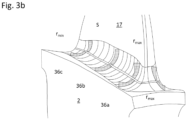
- Fig. 3a and 3b show a second embodiment of a blade-platform connection 3 according to the invention in a spatial, schematic representation on a suction side 16 of a blade 10.
- first embodiment shows a first embodiment of a blade-platform connection 3 according to the invention in a spatial, schematic representation on a suction side 16 of a blade 10.
- a first section 36a with the properties described above for the first embodiment is arranged in a front region of the blade-platform connection 3 in spatial proximity to the front edge 12 of the blade 10.
- the distance to the front edge 12 along the longitudinal extension of the fillet is 20% or less. This means that a maximum ratio between maximum radius r max and minimum radius r min is arranged near the front edge 12.
- a second section 36b of the fillet 30 with properties that differ from the first section 36a is arranged in a central region along the longitudinal extension L of the fillet 30.
- This second section 36b is arranged on the pressure side and has a ratio of the maximum radius r max to the minimum radius r min of less than 1.5.
- the radius along the transverse extension Q of the fillet 30 in the second section 36b is particularly preferably constant.
- the second section 36b can preferably be projected onto the blade chord S from the leading edge 12 and/or the trailing edge 13 at a distance of at least 30% of the blade chord length. This advantageously achieves a uniform radius profile in the blade center in the longitudinal extension L of the fillet 30.
- a third section 36c of the fillet is provided in a rear region of the fillet 30 near the trailing edge 13 of the blade 10, which is similar to the first section but has a smaller ratio of maximum radius r max to minimum radius r min .
- a fillet 30 according to the first embodiment according to the illustrations in the Fig. 2a and 2 B which describes the fillet course on the suction side 16 of the blade 10
- a fillet 30 according to the second embodiment according to the representations of the Fig. 3a and 3b which describes the fillet course on the pressure side 17.
- the first section can be at the same height or with a maximum 10% deviation along the chord S of the blade 10 as the second section 36b. This directs crack propagation to one side of the blade, so that the probability of a disk crack is advantageously reduced on the more highly loaded pressure side 17 of the blade 10.
Landscapes
- Engineering & Computer Science (AREA)
- Mechanical Engineering (AREA)
- General Engineering & Computer Science (AREA)
- Architecture (AREA)
- Chemical & Material Sciences (AREA)
- Materials Engineering (AREA)
- Physics & Mathematics (AREA)
- Fluid Mechanics (AREA)
- Ceramic Engineering (AREA)
- Structures Of Non-Positive Displacement Pumps (AREA)
Abstract
Description
- Die Erfindung betrifft eine Blisk für eine Gasturbine, umfassend zumindest eine Schaufel, mit einem Schaufelblatt und einem Schaufelfuß, eine Plattform, insbesondere eine Rotorplattform, wobei die Schaufel an der Plattform integral befestigt ist, einem Fillet an dem Schaufelfuß und zwischen dem Schaufelblatt und der Plattform, wobei sich das Fillet mit einer Längserstreckung um den Schaufelfuß und einer Quererstreckung von der Plattform zu dem Schaufelblatt erstreckt, wobei das Fillet entlang der Quererstreckung einen variablen Radius aufweist.
- Rotorschaufeln in Strömungsmaschinen unterliegen hohen mechanischen Lasten, die insbesondere durch Fliehkräfte, Schwingungen und Thermalgradienten hervorgerufen werden. Bei lokaler Überbeanspruchung können Risse im Material der Schaufeln auftreten, die unter Einfluss der mechanischen und thermischen Spannungen in das Bauteil wachsen. Insbesondere bei integral beschaufelten Rotoren, beispielsweise bei Blisks (bladed disk) oder Blings (bladed ring) bestehen Schaufeln und Scheibe beziehungsweise Ring aus einem integralen oder monolithischen Bauteil. Weiterhin muss berücksichtigt werden, dass Fremdkörper in das Triebwerk eintreten können und bei einem Auftreffen auf die Schaufeln an diesen Schaden und insbesondere Risse verursachen können. Vor allem aufgrund der Kombination dieser Umstände können Risse von den Schaufeln in den Scheiben- oder Ringkörper wandern und unter Umständen sogar ein Versagen des gesamten Bauteils herbeiführen. Dieses Risswachstum ist nicht erwünscht.
- Um diesem Versagen zu begegnen sind beispielsweise aus der
EP 3 473 431 A1 sogenannte Doppelfillets bekannt, die zwei konkave Bereiche mit einem dazwischen liegenden Podest verbinden, so dass das Risswachstum von der Rotorscheibe weg und in die Schaufel stattfindet. Diese Filletform ist nicht für alle Einsatzzwecke geeignet. Beispielsweise können Randbedingungen aufgrund aerodynamischer Überlegungen den Einsatz derartiger Fillets verhindern. - Konkave Fillets mit variablem Radienverlauf sind bereits aus der
EP 4 019 741 A1 bekannt. Die dort gezeigten Schaufelblätter sind Teil von Turbinenschaufeln mit einem äußeren und einem Inneren Deckband, wobei ein das Schaufelblatt und das innere Deckband verbindende innere Fillet einen minimalen Radius in einem plattformnahen Bereich einer Quererstreckung des Fillets aufweist. Ferner weisen die Schaufeln einen Wurzelbereich auf, der zur Verbindung mit einer Rotorscheibe dient. Nach außen hin nimmt der Radius im Wesentlichen bis zu einem Maximalwert zu und nimmt dann wieder ab, wobei Maximalwerte des Radienverlaufs in der Nähe des Schaufelblatts, aber von dem Schaufelblatt beabstandet angeordnet ist. Die so gestalteten Fillets verringern eine Belastung der Schaufelblätter, nicht aber der Verbindung der Schaufel mit der Plattform. - Rotoren und/oder Blisks sind auf einer Triebwerkswelle angeordnet, mit der sie um eine Triebwerksachse rotieren. Zur Beschreibung der in den Triebwerken vorkommenden Geometrien sind daher drei Hauptachsen definiert. Die erste Hauptachse verläuft in Richtung der Triebwerksdrehachse und wird auch als Längsachse bezeichnet, die in Axialrichtung verläuft. Durch die erste Hauptachse wird ein Vorne und ein Hinten der jeweils betrachteten Geometrie festgelegt, wobei vorne der Eintritt und hinten der Austritt des Strömungsgases erfolgt. Die zweite Achse verläuft entlang einer auf der Triebwerksdrehachse senkrecht stehenden Richtung und wird auch als Radialachse bezeichnet, die in Radialrichtung verläuft. Durch die zweite Hauptachse wird ein Außen und ein Innen des Triebwerks bestimmt, wobei innen die Triebwerksachse liegt und die Radialrichtung von der Triebwerksachse nach außen verläuft. Die dritte Hauptachse verläuft in Umfangsrichtung senkrecht zu den beiden anderen Hauptachsen und verbindet die durch die ersten beiden Hauptachsen gebildeten Meridianschnitte. Die drei Hauptachsen bestimmen zusammen drei Hauptebenen: Meridianebenen, die von der Längsachse und jeweils einer Radialachse aufgespannt sind; Umfangsebenen, die auf einer Zylindermantelfläche um die Drehachse liegen; und Querschnittebenen des Triebwerks, die normal zu der Triebwerksdrehachse angeordnet sind.
- Schaufeln mit komplexer räumlicher Geometrie werden normalerweise durch übereinander gestapelte Schaufelprofile beschrieben, deren Profilflächenerstreckungen nicht zwingend in nur einer Umfangsebene liegen müssen, sondern als geschwungen ausgeführte Schaufelprofile auch die anderen Hauptebenen schneiden können. Diese Gestaltung ist hauptsächlich der aerodynamischen Konstruktion der Schaufeln und der Vorgaben an den Hauptströmungskanal, dessen Ränder, insbesondere das Innendeckband, nicht achsparallel zur Hauptachse verlaufen müssen, geschuldet. Die endgültige Form, insbesondere im Naben- beziehungsweise Deckbandbereich, weicht zusätzlich aus strukturmechanischen Gründen von diesem aerodynamisch optimierten, insbesondere idealen, Schaufelprofil ab; in den meisten Fällen sind in diesem Deckbandbereich sogenannte Fillets angeordnet. Die geometrischen Schwerpunkte der aerodynamisch optimierten Schaufelprofile bilden eine Stapellinie, wobei die Stapellinie ein Maß für die Neigung (engl. "pitch") der Schaufel darstellt.
- Schaufelprofile werden ferner durch eine von der Vorderkante zu der Hinterkante des Schaufelprofils verlaufende Skelettlinie (engl. "camber line"), sowie durch die das Schaufelprofil um laufenden und typischerweise eine Tropfenform mit Saug- und Druckseite bildenden Randlinien an der Schaufeloberfläche beschrieben.
- Die Skelettlinie ist die Profilmittellinie von der Vorderkante zu der Hinterkante der Schaufel und entspricht einer Verbindungslinie durch alle Mittelpunkte von in das Schaufelprofil einbeschriebenen Kreisen. Diese Verbindungslinie kann in einfachster Näherung durch aneinandergereihte Geraden, aber auch durch Splines oder andere polynom iale Kurven durch die Mittelpunkte, beschrieben werden. Bei einer axialen Unterteilung der Schaufel in hundert Teile und mehr, beispielsweise durch hundert axial äquidistant zu einander beabstandete einschreibende Kreise und entsprechende Verbindung der Kreismittelpunkte durch Geraden, ist eine hinreichende Genauigkeit für den Verlauf der Skelettlinie erreicht, die einen zumindest ersten Anhaltspunkt bei der Bestimmung der geometrischen Lagen der beteiligten Punkte dienen kann.
- Vorder- und Hinterkante können ebenfalls durch Kreisabschnitte gebildet werden, da man in Strömungsmaschinen und gerade in den Hauptgaskanälen dieser Strömungsmaschinen scharfe Kanten vermeiden möchte. Nachfolgend sollen Vorderkante und Hinterkante aber auf eine Linie, das heißt eine Aneinanderreihung von Punkten auf der Oberfläche der Schaufel reduziert sein. Um einen Punkt dieser Vorderkantenlinie beziehungsweise Hinterkantenlinie auf einem Profil als Vorderkantenpunkt beziehungsweise als Hinterkantenpunkt festzulegen, dient folgendes Verfahren. Es lassen sich einschreibende Kreise bis an die Vorderbeziehungsweise Hinterkante der Schaufeln legen. An der Vorderkante und an der Hinterkante verläuft die Skelettlinie von dem Vorderkantenkreismittelpunkt bzw. von dem Hinterkantenkreismittelpunkt gerade in Richtung auf die Vorder- bzw. Hinterkante zu. In guter Näherung entspricht diese Richtung der Richtung der Verbindungslinie des vorletzten zum letzten Kreismittelpunkt der jeweiligen einschreibenden Kreise, weil in diesem Bereich mit einem stetigen und konvergierenden Verlauf der Skelettlinie zu rechnen ist, wenn die Kreismittelpunkte ausreichend nahe beieinander liegen, das heißt wenn die Staffelung der betrachteten Geometriepunkt ausreichend fein ist. Diese Definition dient zur Bestimmung der Vorder- und Hinterkante insbesondere bei unbekannter Schaufelgeometrie, das heißt nicht aus der Konstruktion vorliegenden Daten zu der Schaufelgeometrie. Eine von der Vorderkante zu der Hinterkante aufgespannte gerade Linie wird als Schaufelsehne (engl. "chord) bezeichnet. Wenn nicht anders angegeben, sind Angaben, die auf die Sehnenlänge bezogen sind, als auf die Sehnenlänge projizierte Oberflächenpunkte der darüber- oder darunterliegenden Struktur in beziehungsweise entgegen der Umfangsrichtung zu verstehen.
- Es wird zur Bestimmung der quantitativen Größen als hinreichend approximiert angesehen, wenn die Lage der zu bestimmenden Punkte der entsprechenden Schaufelgröße (axiale Erstreckung, radiale Erstreckung, Umfangserstreckung) zumindest auf ein Zwanzigstel der Ausdehnung der Schaufel in der entsprechenden Raumrichtung genau bestimmt werden kann. Wenn es Anhaltspunkte dafür gibt, dass eine feinere Staffelung nötig wäre oder betrachtete Geometrien sehr eng an dieser Beschreibung und in den Ansprüchen genannte Werte heranreichen, sollte diese Approximation entsprechend verfeinert werden.
- Als maximale Profildicke eines Profils wird der größtmögliche Kreisdurchmesser eines Kreises zwischen Profilsaugseite und Profildruckseite bezeichnet, wobei der Mittelpunkt dieses größten Kreises auf der Skelettlinie angeordnet ist. Eine Anbindungsfläche zu einer Rotornabe bzw. zu einem Rotordeckband wird als Schaufelfuß bezeichnet.
- Da man bemüht ist, Verwirbelungen und damit Verluste in Triebwerken möglichst gering zu halten und ungewollte Spannungen im Material der Schaufeln und der Plattform der Scheibe, die auch als Nabe, Rotornabe, Deckband oder Innendeckband bezeichnet wird, zu vermeiden oder zu verteilen, so dass die ungewollten Spannungen unschädlich sind, werden die Übergänge von der Schaufel zu der Plattform im Bereich des Schaufelfußes durch das Vorsehen eines Fillets möglichst stetig ausgestaltet. Dadurch entstehen von dem aerodynamisch idealen beziehungsweise optimierten Schaufelprofil abweichende Geometrien, so dass die genaue Lage der Vorder- und Hinterkante durch das oben beschriebene Vorgehen möglicherweise nicht mehr eindeutig bestimmt werden kann, denn die Kreisformen der Schaufelenden an der Vorderkante und an der Hinterkante werden durch das Vorhandensein eines Fillets, also einer von einer aerodynam isch optim ierten Form abweichenden Form der Schaufel, aufgelöst. Erschwerend kommt hinzu, dass die bei der Konstruktion berechneten Schaufelprofile nicht entlang einer zylindrischen Umfangsebene definiert sind, sondern diese schneiden können. Ferner kann im Bereich des Schaufelfußes die Plattform- beziehungsweise Naben- oder Deckbandkonturierung (engl. "endwall contouring") des Rotorgrundkörpers an die Strömung angepasst sein, was wiederum erschwerend für das Auffinden des Beginns des Fillets ist.
- Bei der Bestimmung der Größen einer solchen zu vermessenden Schaufel, insbesondere einer Anbindungsstruktur wie ein Fillet, können die Oberflächen der Schaufel und der Plattform sowie des Übergangs, dem Fillet, zwischen Schaufel und Plattform beispielsweise optisch vermessen werden. Die genaue Lage der Vorder-und Hinterkante, der genaue Anbindungsbereich von dem aerodynamisch idealen Profil auf ein Fillet und der Anbindungsbereich von dem Fillet auf die Plattform der Rotorscheibe sind dennoch nur schwer zu bestimmen. Innen liegende Größen sind in der Regel nicht bekannt und die Übergänge an der Oberfläche von dem Schaufelblatt auf das Fillet, was im Folgenden als Schaufelverbindung bezeichnet wird, und weiter auf die Plattform der Blisk- beziehungweise Rotorscheibe, was im Folgenden als Plattformverbindung bezeichnet wird, sind aufgrund der aerodynamischen Form der Schaufel in der Regel stetig. Das heißt ein genauer Übergangspunkt ohne Kenntnisse der Strömung und dem Auslegungspunkt der Schaufeln ist ebenfalls nur schwer genau zu bestimmen.
- Um ein Bestimmen der quantitativen Größen von zu vermessenden Schaufeln bei Unkenntnis der aerodynamischen Verhältnisse und der konstruktiven Überlegungen zunächst hinreichend in guter Näherung zu ermöglichen, werden Schnitte durch die Schaufel herangezogen, die in einer der Hauptebenen liegen, wobei eine Staffelung der Abstände zur näherungsweisen Bestimmung der betrachteten Geometrien entlang der drei Hauptachsen jeweils mindestens um ein Hundertstel von der größten Längserstreckung der Schaufel, der größten Radialerstreckung der Schaufel und der größten Umfangserstreckung der Schaufel erfolgt. Mit anderen Worten wird ein Gitter (analog zu einem Gitter bei einer Finiten Elemente Methode, abgekürzt FEM) mit einer Feinheit von in jeweils mindestens zwanzig Schritten in allen drei Hauptrichtungen, nämlich zwischen dem vordersten und hintersten Punkt der Schaufel, den am weitesten innen und außen liegenden Punkten der Schaufel sowie zwischen den in Umfangsrichtung am weitesten auseinander liegenden Punkten der Schaufel gelegt.
- Die größten Umfangs- und Axialerstreckungen der Schaufel sind an der Plattform zu erwarten, weil dort der Anbindungsbereich, das Fillet, von dem Schaufelfuß zu dem Rotorgrundkörper erfolgt und der Schaufelfuß die größte Ausdehnung aufweist.
- Um den axialen Beginn und das axiale Ende, also die Anbindungspunkte, des Fillet in axialer Richtung zu bestimmen, ist die Kontur der Oberfläche im Bereich der Plattform zu betrachten. Liegt in beziehungsweise entgegen der axialen Richtung an den Anbindungsbereich angrenzend eine Vertiefung der Plattform vor, so wird der Anbindungspunkt des Fillets auf die Plattform ein Wendepunkt der Oberfläche sein. Liegt in beziehungsweise entgegen der axialen Richtung eine Erhöhung der Plattform vor, so wird der Anbindungspunkt ein minimaler radialer Abstand der Oberfläche zu der Rotordrehachse sein. Liegt in der betrachteten Ebene eine Erstreckung mit einem geraden Verlauf der Plattform vor, so wird der Anbindungspunkt durch einen Beginn einer Krümmung definiert.
- Um den Umfangsbeginn oder das Umfangsende des Fillets in Umfangsrichtung zu bestimmen, ist die Kontur der Oberfläche im Bereich der Plattform zu betrachten. Ein Übergang von der Oberfläche der Plattform auf eine Anbindungsstruktur, beispielsweise ein Fillet, kann in einem Bereich erwartet werden, in dem sich die Krümmung der Oberfläche ändert. Liegt in beziehungsweise entgegen der Umfangsrichtung an den zu erwartenden Bereich, in dem sich der Übergang befinden soll, angrenzend eine Vertiefung vor, so wird der Übergangspunkt des Fillets auf die Plattform ein Wendepunkt der Oberfläche sein. Liegt in beziehungsweise entgegen der Umfangsrichtung eine Erhöhung der Plattform vor, so wird der Übergangspunkt ein minimaler radialer Abstand der Oberfläche zu der Rotorachse sein. Liegt in der betrachteten Ebene eine Erstreckung der Plattform mit einem geraden Verlauf vor, so wird der Übergangspunkt durch einen Beginn einer Krümmung definiert.
- Der axiale Beginn und das axiale Ende des Fillets sowie der Umfangsbeginn und das Umfangsende des Fillets sind Punkte, die jeweils einen radialen Abstand zu der Drehachse der Strömungsmaschine aufweisen. Über denjenigen dieser Punkte mit dem geringsten radialen Abstand lässt sich eine Umfangsebene als Zylindermantelfläche definieren, die im Folgenden ein Hilfsdeckband der Plattform definiert und als Anknüpfungspunkt für die Ermittlung der radialen Erstreckung der Schaufel, so auch der maximalen radialen Erstreckung, in erster Näherung dient.
- Die größte radiale Erstreckung des Schaufelblatts lässt sich dann hilfsweise durch Bilden eines weiteren Zylinders um die Triebwerksdrehachse bilden, dessen Mantelfläche nur einen einzigen, nämlich den äußersten Punkt der Schaufel schneidet.
- Aus diesen maximalen Erstreckungen lassen sich die Staffelungen oder Gitter für die Bestimmung sämtlicher Größen der Schaufel wie oben angegeben herleiten, insbesondere Gitter deren Kantenlängen jeweils ein Zwanzigstel oder weniger von der maximalen Längs-, Radial- und Umfangserstreckung der Schaufel betragen. Die Feinheit der Gitter sollte von den betrachteten Größen abhängen, um mit ausreichender Sicherheit einen Vergleich mit den Größen herstellen zu können.
- Um einen Anbindungspunkt von dem Schaufelblatt auf eine Anbindungsstruktur, zum Beispiel einem Fillet, des Schaufelblatts auf die Plattform bei unbekannten Strömungsverhältnissen oder ohne Kenntnis der zugrundeliegenden strukturmechanischen Überlegungen zu bestimmen, wird die Schaufel wie oben beschrieben in eine Gitterunterteilung der Meridianebenen, der Querschnittsebenen sowie der Umfangsebenen eingefasst. Es werden dann für die Bestimmung der Anbindungspunkte von Schaufelblatt zu der Anbindungsstruktur in erster Näherung diejenigen Punkte der Schaufeloberfläche in dem Bereich, in dem der Beginn der Anbindungsstruktur zu erwarten ist, bestimmt, die gegenüber zumindest einem entlang der Oberfläche betrachtet radial äußeren und inneren Nachbarpunkten eine größere Krümmungsänderung aufweisen. Für die Bestimmung der Anbindungspunkte von der Anbindungsstruktur auf die Plattform wird analog verfahren, wobei hier sowohl die in axialer Richtung als auch in Umfangsrichtung benachbarten Punkte auf der Oberfläche der Schaufel beziehungsweise der Plattform zum Vergleich der Krümmungsänderung herangezogen werden. Nach Bestimmung der Anbindungsbereiche sollten nunmehr die vermessenen Oberflächen sowie Anfang und Ende der Anbindungsstruktur in radialer Richtung bekannt sein. In der jeweiligen Umfangsebene der Vorderkante und der Hinterkante kann eine Erweiterungslinie, die auch als Extrusionslinie bezeichnet werden kann, der zur Bestimmung der Vorderkante beziehungsweise Hinterkante herangezogenen Geraden erzeugt werden. Von dieser Erweiterungslinie kann auf die Anbindungsstruktur bis zum Schaufelfuß eine Linie in radialer Richtung projiziert werden, die im Folgenden auf der Anbindungsstruktur als Vorderkante beziehungsweise Hinterkante dienen soll. In den Fällen, in denen die Schaufeln und deren Anbindungsstrukturen aufgrund einer geometrischen Begrenzung der Scheibe in axialer Richtung durchschnitten sind, kann es zwei Vorderkanten oder Hinterkanten in diesem Bereich geben, von denen an die entsprechenden anderen Größen zur Beschreibung der Anbindungsstruktur zu bestimmen sind. Entlang jedem der Anbindungsbereiche können jeweils zwischen Vorderkante und Hinterkante zumindest jeweils zumindest zwanzig Gitterpunkte gelegt werden, wobei zwei gegenüberliegende Punkte der beiden auf entweder der Saugseite oder der Druckseite angeordneten Anbindungsbereiche entlang der gemessenen Oberfläche verbunden werden, so dass eine entsprechend feine Unterteilung der Anbindungsstruktur ermöglicht wird. Hieraus lassen sich die Ausdehnungen der in dieser Anmeldung beschriebenen Bereiche der Anbindungsstruktur, das heißt des Fillets, und dessen Varianten zumindest in erster Näherung bestimmen.
- Bei den oben beschriebenen Verfahren zur Bestimmung der Größen und Lagen handelt es sich um erste Näherungsverfahren, um eine unbekannte Schaufel einordnen zu können. Eine Überprüfung sollte wenn geboten in einem weiteren Schritt möglichst anhand der genauen Geometrie und der Kenntnis der Anbindungen vorgenommen werden. Genauere Ergebnisse liefert das Heranziehen tatsächlicher Größen beispielsweise aus Konstruktionszeichnungen.
- Es ist die Aufgabe der Erfindung eine Bliskanzugeben, deren Sicherheitsverhalten bei Schadenseinwirkung oder extremer Belastung verbessert ist.
- Diese Aufgabe wird erfindungsgemäß von einer Bliskgemäß Anspruch 1 und einer Verdichterblisk gemäß dem Anspruch 12 gelöst.
- Eine solche erfindungsgemäße Blisk in einer Gasturbine umfasst zumindest eine Schaufel mit einem Schaufelblatt und einem Schaufelfuß, eine Plattform, insbesondere eine Rotorscheibenplattform, wobei die Schaufel an der Plattform integral befestigt ist, ein an dem Schaufelfuß und zwischen dem Schaufelblatt und der Plattform angeordnetes Fillet, wobei das Fillet in das Schaufelblatt an einer Schaufelverbindung übergeht und wobei das Fillet in die Plattform an einer Plattformverbindung übergeht. Das Fillet erstreckt sich mit einer Längserstreckung um den Schaufelfuß und einer Quererstreckung von der Plattformverbindung an der Plattform zu der Schaufelverbindung an dem Schaufelblatt, wobei das Fillet entlang der Quererstreckung einen variablen Radius aufweist. Die zumindest eine Schaufel, die Plattform und die entsprechende Verbindung umfassend das Fillet bilden eine Schaufel-Plattform-Verbindung, wobei auch unterschiedliche Schaufel-Plattform-Verbindungen an einer Blisk vorgesehen sein können.
- Die Aufgabe wird von der erfindungsgemäßen Blisk dadurch gelöst, dass der variable Radius zumindest in einem ersten Abschnitt des Fillets einen minimalen Radius aufweist, der zumindest in dem ersten Abschnitt entlang der Quererstreckung des Fillets zu der Plattform mindestens 15%, bevorzugt mindestens 30%, der Quererstreckung beabstandet ist. Durch den Abstand zur Plattform wird vorteilhaft erreicht, dass es im Schadensfall nicht zu einem Riss in die Plattform und damit die Rotorscheibe kommt. Ein solcher Abstand des minimalen Radius zu der Plattform stellt somit eine Rissbeeinflussungseinrichtung dar. Hierdurch wird vorteilhaft ein erstes Entkopplungsmittel statischer und dynamischer Spannungen in der Schaufel in die Geometrie eingeführt. Dadurch wird die Gefahr eines Scheibenversagens deutlich reduziert. Es kann vorgesehen sein, dass der Abstand zu der Plattform mindestens 35%, insbesondere mindestens 40%, besonders bevorzugt mindestens 45% der Quererstreckung des Fillets beträgt. Dadurch kann bei einer Beschädigung der Schaufel ein Risswachstum in die Schaufel und von dem Rotorscheibe weg günstig beeinflusst werden. Ergänzend kann vorgesehen sein, dass der minimale Radius nicht nur linienförmig, sondern auch bandförmig ausgebildet ist. Der minimale Radius kann zumindest in dem ersten Abschnitt über einen mittleren Bereich der Quererstreckung konstant sein. Entsprechend ist der variable Radius als Funktion zu betrachten, die auch streckenweise konstante Werte aufweisen kann. Das so gebildete Strukturband eines minimalen Radius kann sich entlang der Längserstreckung des Fillets erstrecken, wobei das Fillet entlang der Querstreckung in dem Strukturband einen Radius mit konstanten Minimalwert oder eine Gerade aufweisen kann. Der erste Abschnitt des Fillets kann 5% der Längserstreckung des Fillets ausmachen. Es kann aber auch vorgesehen sein, dass der erste Abschnitt größer oder kleiner ist. So kann der erste Abschnitt 2%, 3% oder 4% der Längserstreckung des Fillets ausmachen, der erste Abschnitt kann aber auch 10%, 15% oder 20% der Längserstreckung des Fillets ausmachen.
- Weitere Merkmale der Erfindung werden in den abhängigen Ansprüchen und den Zeichnungen beschrieben. Diese Merkmale stellen weitere Aspekte der oben angegebenen Rissbeeinflussungseinrichtung dar.
- In einer bevorzugten Ausgestaltung der Erfindung kann der minimale Radius entlang der Quererstreckung des Fillets zu dem Schaufelblatt mindestens 30% der Quererstreckung beabstandet sein. Dadurch kann vorteilhaft sichergestellt werden, dass auch Schäden, die auf niedriger radialer Höhe der Schaufel auftreten, nicht zu einem Risswachstum in die Scheibe führen, sondern in der Schaufel verlaufen. Hierdurch kann vorteilhaft ein zweites Entkopplungsmittel statischer und dynamischer Spannungen in der Schaufel in die Geometrie eingeführt werden. Es kann vorgesehen sein, dass die Distanz zu dem Schaufelblatt mindestens 35%, insbesondere mindestens 40%, besonders bevorzugt mindestens 45% der Quererstreckung des Fillets beträgt. Die so erhaltene Struktur des Radius des Fillets entlang der Quererstreckung ist wannenförmig bzw. U-förmig.
- In einer weiteren bevorzugten Ausbildung der Blisk ist das Fillet entlang seiner Quererstreckung zumindest in dem ersten Abschnitt vollständig konkav ausgebildet ist. Dadurch, dass keine konvexen oder geraden Bereiche vorgesehen werden, können die Bauteilspannungen günstig verteilt werden und es kommt vorteilhaft neben den geringeren aerodynamischen Auswirkungen zu geringeren mechanischen Spannungsspitzen.
- Darüber hinaus kann vorgesehen sein, dass auch der Verlauf der Radien des Fillets entlang seiner Quererstreckung zumindest in dem ersten Abschnitt vollständig konkav ist. D.h. der Verlauf der Radien hat eine monoton steigende erste Ableitung entlang der Quererstreckung mit einem Nulldurchgang beim minimalen Radius.
- Darüber hinaus kann in einer weiteren Ausbildung der Blisk vorgesehen sein, dass der minimale Radius zumindest in dem ersten Abschnitt 5 mm oder weniger, insbesondere 3mm oder weniger, besonders bevorzugt 2mm oder weniger beträgt. Derart geringe Radien erlauben eine gezielte Beeinflussung der Materialspannungen, so dass vorteilhaft eine Rissausbreitung in die Scheibe verringert oder verhindert werden kann. Besonders vorteilhaft ist damit ein drittes Entkopplungsm ittel angegeben, das es erlaubt statische und dynamische Spannungen gezielt getrennt voneinander zu beeinflussen. Es kann vorgesehen sein, dass der minimale Radius höchstens 5 mm, insbesondere höchstens 4 mm beträgt. Dies bedeutet, dass der übrige Radienverlauf größere Werte aufweist, was eine besonders gute Verteilung von Oberflächenspannungen erlaubt.
- In einer weiteren Ausbildung der Blisk weist der variable Radius zumindest in dem ersten Abschnitt einen maximalen Radius an dem Schaufelblatt und/oder an der Plattform auf, wobei der variable Radius entlang der Quererstreckung des Fillets insbesondere einen monoton fallenden Verlauf zwischen dem maximalen Radius und dem minimalen Radius aufweist. Dadurch kann zwischen dem Fillet und der Schaufel eine Schaufelverbindung mit einem maximalen Radius gebildet sein, und/oder es kann dadurch zwischen dem Fillet und der Plattform eine Plattformverbindung mit einem maximalen Radius gebildet sein. Dadurch, dass der maximale Radius an der Schaufelverbindung und/oder an der Plattformverbindung ausgebildet ist, gibt es entlang der Quererstreckung des Fillets keine lokalen Spannungskonzentrationen, die zu einem Bauteilversagen beitragen könnten.
- Ferner kann in einer noch weiteren Ausführungsform zumindest in dem ersten Abschnitt ein Verhältnis des minimalen Radius zu dem maximalen Radius an dem Schaufelblatt und/oder an der Plattform mindestens 1.5, insbesondere mindestens 5, besonders bevorzugt mindestens 5betragen. Durch eine solche Radienverteilung entlang der Quererstreckung in zumindest einem Abschnitt entlang der Längserstreckung des Fillets kann eine gezielte Spannungserhöhung zur Rissbeeinflussung herbeigeführt werden.
- In einer ergänzenden oder alternativen Ausführungsform der Blisk, wobei die Schaufel eine Schaufelsehne aufweist, die sich von einer Vorderkante zu einer Hinterkante erstreckt, kann vorgesehen sein, dass ein Verhältnis des maximalen Radius zu dem minimalen Radius an dem Schaufelblatt und/oder an der Plattform an einem Maximalpunkt des Fillets, der zwischen 5% und 95% einer Schaufelsehne angeordnet ist, maximal ist. Die projizierte Distanz des Maximalpunktes auf die Schaufelsehne zu der Vorderkante beträgt mindestens 5% der Sehnenlänge der Schaufel. Dadurch kann bei einer Beschädigung der Schaufel ein Risswachstum in die Schaufel und von dem Rotorscheibe weg günstig beeinflusst werden. Es kann vorgesehen sein, dass die Distanz zu der Plattform mindestens 5%, 10%, 15%, 20%, bevorzugt mindestens 25%, 30%, 35%, insbesondere mindestens 40%, oder besonders bevorzugt mindestens 45% der Quererstreckung des Fillets beträgt. Es kann vorgesehen sein, dass die Distanz zu dem Schaufelblatt mindestens 5%, 10%, 15%, 20%, bevorzugt mindestens 25%, 30%, 35%, insbesondere mindestens 40%, oder besonders bevorzugt mindestens 45% der Quererstreckung des Fillets beträgt. Es kann vorgesehen sein, dass der Maximalpunkt in dem ersten Abschnitt angeordnet ist.
- In einer weiteren Ausführungsform kann vorgesehen sein, dass das Fillet einen von dem ersten Abschnitt beabstandeten oder angrenzenden zweiten Abschnitt aufweist, wobei zumindest in dem zweiten Abschnitt ein Verhältnis des maximalen Radius zu einem minimalen Radius an dem Schaufelblatt und/oder an der Plattform höchstens 1,5, insbesondere höchstens 1,2, besonders bevorzugt höchstens 1,1, beträgt. Insbesondere können so gezielt Bereiche geschaffen werden, die besonders einer der statischen oder dynamischen Spannungen widerstehen kann. Dadurch ist vorteilhaft ein viertes Entkopplungsmittel angegeben, das es erlaubt statische und dynamische Spannungen gezielt getrennt voneinander zu beeinflussen.
- Gemäß einem weiteren Aspekt der Erfindung kann das Verhältnis des maximalen Radius (rmax) zu dem minimalen Radius (rmin) an der Saugseite größer sein als an der Druckseite des Schaufelblatts, insbesondere kann das Verhältnis an der Saugseite im mittel doppelt so groß, bevorzugt dreimal so groß, wie an der Druckseite sein.
- In einer bevorzugten weiteren Ausbildungsform verläuft der erste Abschnitt von einer Vorderkante bis zu einer Hinterkante der Schaufel. Es kann aber auch vorgesehen sein, dass der erste Abschnitt zwischen 30% und 70% einer Schaufelsehne des Fillets verläuft. Weiterhin sind auch andere oder kleinere lokale Abschnitte vorgeschlagen, welche die Eigenschaften des ersten Abschnitts aufweisen. So kann ein solcher Abschnitt beispielsweise von der Vorderkante mindestens 5%, 10%, 15%, 20%, 25%, 30%, 35%, 40% oder 45% der Sehnenlänge beabstandet sein. Ein solcher Abschnitt kann beispielsweise auch von der Hinterkante mindestens 5%, 10%, 15%, 20%, 25%, 30%, 35%, 40% oder 45% der Sehnenlänge beabstandet sein.
- Darüber hinaus kann in einer weiteren Ausführungsform ergänzend vorgesehen sein, dass der erste Abschnitt auf der Druckseite und/oder der Saugseite der Schaufel angeordnet ist. Die Anordnung des ersten Abschnitts auf der Saug- und/oder Druckseite kann gezielt dazu eingesetzt werden, die statischen Spannungen aufgrund einer Schaufelneigung auszugleichen. Dadurch ist ein fünftes Entkopplungsm ittel angegeben, das es erlaubt statische und dynamische Spannungen gezielt getrennt voneinander zu beeinflussen.
- In einer vorteilhaften Weiterbildung kann die Blisk so ausgebildet sein, dass der erste Abschnitt auf der Saugseite der Schaufel angeordnet ist und der zweite Abschnitt auf der Druckseite der Schaufel angeordnet ist. Durch diese gegenüberliegende Anordnung der beiden unterschiedlichen Abschnitte des Fillets können Spannungen, die aufgrund einer Neigung der Schaufel auftreten, besonders vorteilhaft beeinflusst werden.
- Eine weitere bevorzugte und ggf. unabhängig zu beanspruchende Ausführungsform einer erfindungsgemäßen Blisk in einer Gasturbine umfasst zumindest eine Schaufel mit einem Schaufelblatt und einem Schaufelfuß, eine Plattform, insbesondere eine Rotorscheibenplattform, wobei die Schaufel an der Plattform integral befestigt ist, ein an dem Schaufelfuß und zwischen dem Schaufelblatt und der Plattform angeordnetes Fillet, wobei das Fillet in das Schaufelblatt an einer Schaufelverbindung übergeht und wobei das Fillet in die Plattform an einer Plattformverbindung übergeht. Das Fillet erstreckt sich mit einer Längserstreckung um den Schaufelfuß und einer Quererstreckung von der Plattformverbindung an der Plattform zu der Schaufelverbindung an dem Schaufelblatt, wobei das Fillet entlang der Quererstreckung einen variablen Radius aufweist. Die zumindest eine Schaufel, die Plattform und die entsprechende Verbindung umfassend das Fillet bilden eine Schaufel-Plattform-Verbindung, wobei auch unterschiedliche Schaufel-Plattform-Verbindungen an einer Blisk vorgesehen sein können.
- Die Aufgabe wird gelöst durch ein composite Fillet. Hierbei ist der radiale Offset/Abstand der Schaufelverbindung von der Plattformverbindung ABdist größer als der Offset in Umfangsrichtung gesehen der Plattformverbindung relativ zur Schaufelverbindung EBdist. Die genauere Definition der Begrenzungskurven stellt (zusätzlich zum bereits eingereichten Patent der qualitativen Radienverläufe) eine weitere Beeinflussungsmöglichkeit zur Steuerung der statischen und dynamischen Lastverteilung des Bauteils dar. Auch dieses Element trägt somit zu einer Erhöhung der Schadentoleranz (kein Risswachstum in die Scheibe) bei.
- Während der strukturmechanischen Auslegungsarbeit hat sich gezeigt, dass sogenannten "composite Blends" positiv Auswirkungen auf eine Separation der statischen und dynamischen Lasten haben.
- Neben den Radienverläufe der Filletkontur sind hierbei auch die Definitionen der rotorseitigen Begrenzungskurve (Endwall Boundary / Plattformverbindung) sowie der schaufelseitigen Begrenzungskurve (Airfoil Boundaryn/ Schaufelverbindung) von entscheidender Bedeutung.
- Gemäß dem vorliegenden Teilaspekt der Erfindung kann basierend auf der maximalen Profildicke(tmax0) Blisk-Schaufel bzw. des Alrfoils die Begrenzungskurven parametrisch definiert werden.
- Die Plattformverbindung / Endwall Boundary kann hierbei durch einen rolling Ball, einen variablen rolling Ball oder auch einen Offset der Schaufelobefläche um einen konstanten / variablen Wert erzeugt werden.
- Als Wertebereich für den zu schützenden Bereich gilt EBdist = 0,70 ... 1,35 * tmax0
Die Schaufelverbindung / Airfoil Boundary kann hierbei durch einen rolling Ball, einen variablen rolling Ball oder auch einen Offset der Ringraumoberfläche um einen konstanten / variablen Wert erzeugt werden. - Als Wertebereich für den zu schützenden Bereich gilt ABdist = 0,8 ... 2,0 * tmax0
Zusätzlich gilt in allen Bereich die Anforderung ABdist > EBdist um eine elliptischen Ausprägung des composite Blends zu garantieren. - In anderen Worten kann der radiale Offset/Abstand der Schaufelverbindung von der Plattformverbindung in einem Bereich ABdist = 0,8 ... 2,0 * tmax0 liegen und der Offset in Umfangsrichtung gesehen der Plattformverbindung relativ zur Schaufelverbindung EBdist kann 0,70 ... 1,35 * tmax0 betragen, wobei ABdist größer als EBdist ist.
- Ein weiterer Aspekt der Erfindung betrifft eine Blisk in einer Gasturbine, umfassend zumindest eine Schaufel mit einem Schaufelblatt und einem Schaufelfuß, eine Plattform, insbesondere eine Rotorscheibenplattform, wobei die Schaufel an der Plattform integral befestigt ist, einem Fillet, das an dem Schaufelfuß und zwischen dem Schaufelblatt und der Plattform die Schaufel mit der Plattform verbindet. Das Fillet erstreckt sich mit einer Längserstreckung um den Schaufelfuß und einer Quererstreckung von der Plattform zu dem Schaufelblatt, wobei das Fillet entlang der Quererstreckung einen variablen Radius aufweist. Die Aufgabe wird von dieser weiteren Schaufel-Plattform-Verbindung dadurch gelöst, dass das Fillet ein, insbesondere strukturelles und/oder geometrisches, Entkopplungsmittel von im Betrieb in der Schaufel-Plattform-Verbindung auftretenden statischen und dynamischen Spannungen aufweist.
- Die Erfindung wird bezüglich der nachfolgenden Zeichnungen anhand einiger bevorzugter Ausführungsbeispiele der Erfindung näher erläutert.
- Fig. 1
- zeigt ein Ausführungsbeispiel einer erfindungsgemäßen Verdichterblisk
- Fig. 2a
- zeigt ein erstes Ausführungsbeispiel einer erfindungsgemäßen Schaufel-Plattform-Verbindung auf einer Saugseite einer Schaufel
- Fig. 2b
- zeigt das erste Ausführungsbeispiel einer erfindungsgemäßen Schaufel-Plattform-Verbindung mit beispielhaft eingezeichneten Radienverläufen
- Fig. 3a
- zeigt ein zweites Ausführungsbeispiel einer erfindungsgemäßen Schaufel-Plattform-Verbindung auf einer Druckseite einer Schaufel
- Fig. 3b
- zeigt das zweite Ausführungsbeispiel einer erfindungsgemäßen Schaufel-Plattform-Verbindung mit beispielhaft eingezeichneten Radienverläufen
- In
Fig. 1 ist ein Segment eines Ausführungsbeispiels einer erfindungsgemäßen Blisk 2 perspektivisch dargestellt. Die Blisk 2 ist in einer Gasturbine 1 für ein Flugtriebwerk angeordnet, wobei die Gasturbine 1 in derFig. 1 durch ihre drei Hauptachsen Ax, R, U angedeutet ist. Die drei Hauptachsen verlaufen in Axialrichtung Ax, Radialrichtung R und Umfangsrichtung U. Die Blisk 2 dient als ein Rotor in einem Verdichter der Gasturbine 1. - Die Blisk 2 umfasst eine Bliskscheibe 4 und eine auf der Bliskscheibe 4 angeordnete Vielzahl an als Laufschaufeln bezeichneten Schaufeln 10. Die Schaufeln 10 sind auf einer Plattformoberfläche 22 einer Plattform 20 der Bliskscheibe 4 beabstandet zueinander in Umfangsrichtung U angeordnet. Die Schaufeln 10, die Plattform 20 und ein jeweils eine der Schaufeln 10 und die Plattform 20 verbindendes Fillet 30 bilden gemeinsam eine Schaufel-Plattform-Verbindung 3. Die Schaufeln 10 weisen ein Schaufelblatt 11 zur Aufnahme aerodynamischer Kräfte, einen Schaufelfuß 14 zur Anbindung an der Plattformoberfläche 20 sowie eine zu einer Ringraum wand der Gasturbine 1 weisende Schaufelspitze 15 auf. Die Blisk 2 dreht sich in Umfangsrichtung U, wobei jeweils eine Saugseite 16 der jeweiligen Schaufel 10 entgegen der Drehrichtung und eine Druckseite 17 der jeweiligen Schaufel 10 in Drehrichtung der Blisk 2 angeordnet sind. Saug- und Druckseite 16, 17 erstrecken sich dabei jeweils von einer Vorderkante 12 bis zu einer Hinterkante 13 der jeweiligen Schaufel 10.
- Die Blisken 2 weisen ein besonders robustes Risswachstumsverhalten auf, wobei Risse insbesondere kaum oder gar nicht in die Scheibe eindringen können, sondern vorher die Schaufeln 10 von der Plattform 20 getrennt werden.
- Die Schaufel-Plattform-Verbindungen 3 werden im Folgenden anhand zweier Ausführungsbeispiele in den
Fig. 2a ,2b undFig. 3a ,3b näher erläutert. -
Fig. 2a zeigt ein erstes erfindungsgemäßes Ausführungsbeispiel einer Schaufel-Plattform-Verbindung 3 in einer räumlichen, schematischen Darstellung auf einer Saugseite 16 einer Schaufel 10. Die Schaufel-Plattform-Verbindung 3 umfasst die Schaufel 10, eine Plattform 20 sowie ein Fillet 30, welches die Schaufel 10 und die Plattform 20 miteinander verbindet. Die Schaufel 10 weist wie inFig. 1 beschrieben ein Schaufelblatt 11 und einen Schaufelfuß 14 auf. Das Fillet 30 umgibt den Schaufelfuß 14 entlang seiner Längserstreckung L und erstreckt sich quer zu seiner Längserstreckung L entlang seiner Quererstreckung Q von der Plattform 20 zu dem Schaufelblatt 11. - Das Fillet 30 erstreckt sich in dem Ausführungsbeispiel um und von einer Vorderkante 12 bis zu einer Hinterkante 13 der Schaufel 10, wobei eine Längserstreckung L des Fillets 30 jeweils von der Vorderkante 12 bis zu der Hinterkante 13 definiert ist. Die Hinterkante 13 ist in diesem Ausführungsbeispiel durch einen Schnitt der Blisk 2 gebildet, so dass die Schaufel 10 in einem Bereich des Schaufelfußes 14 zwei Hinterkanten 13 aufweist, die an dem Schaufelblatt 11 zusammenlaufen. Das Fillet 30 endet daher an den Hinterkanten 13 und umrundet diese nicht. Das Fillet 30 grenzt mit einer Schaufelverbindung 32 an die Schaufel 10 beziehungsweise das Schaufelblatt 11 und mit einer Plattformverbindung 34 an die Plattform 20. In Quererstreckung Q ist das Fillet 30 über die gesamte Längserstreckung L konkav ausgebildet und weist einen variablen Radius r auf.
- Der variable Radius r ist in einem mittleren Bereich 38 des Fillets 30 entlang der Quererstreckung Q ein minimaler Radius rmin. Praktischer Weise wird die Längserstreckung L auf der Höhe des minimalen Radius Rmin des Fillets gemessen. Der mittlere Bereich 38 ist bandförm ig ausgebildet und verläuft um die Schaufel 10, wobei sich der minimale Radius rmin an einem Punkt, über einen Teil oder die gesamte Breite des mittleren Bereichs 38 erstrecken kann. So kann eine Fläche gebildet sein, die den minim alen Radius aufweist. Der mittlere Bereich 38 ist von der Schaufelverbindung 32 mindestens 20%, 25% oder 30% der Quererstreckung Q des Fillets 30 beabstandet. Ferner ist der mittlere Bereich 38 von der Plattformverbindung 34 mindestens 30% der Quererstreckung Q des Fillets 30 beabstandet. In Längserstreckung L des Fillets 30 ist der minimale Radius rmin von der Vorderkante 12 mindestens 5%, 10%, 15%, 20%, 25% oder 30% der Längserstreckung L des Fillets 30 beabstandet. Ferner ist der minimale Radius rmin von der Hinterkante 13 mindestens 10%, 15%, 20%, 25% oder 30% der Längserstreckung L des Fillets 30 beabstandet.
- Dadurch ist der minimale Radius rmin vorteilhaft in einem zentralen Bereich des Fillets 30 auf der Saugseite 16 der Schaufel 10 angeordnet. Dies ermöglicht die gezielte Separation von statischen und dynamischen Spannungsmaxima und ist somit zuträglich für die Schadenstoleranz des Bauteils.
-
Fig. 2b zeigt das erste erfindungsgemäße Ausführungsbeispiel der Schaufel-Plattform-Verbindung 3 mit beispielhaft eingezeichneten Radienverläufen r. Der Übersicht halber sind nicht noch einmal alle Bezugszeichen eingezeichnet. - Die variablen Radien r weisen in dem vorliegenden Ausführungsbeispiel entlang der Längserstreckung L in allen Fällen außen und innen an dem Schaufelübergang 32 sowie an dem Plattformübergang 34 einen maximalen Radius rmax auf. In Kombination mit dem minimalen Radius rmin in dem mittleren Bereich 38 ergibt sich somit ein Wannenförmiger beziehungsweise U-förm iger Quererstreckungsverlauf des Fillets 30 entlang seiner Längserstreckung L.
- Sowohl in
Fig. 2a als auch inFig. 2b ist ein erster Abschnitt 36a des Fillets 30 eingezeichnet, der die oben genannten Eigenschaften aufweisen kann. Insbesondere kann an einem Maximalpunkt M ein Verhältnis des größeren maximalen Radius rmax zu dem minimalen Radius rmin maximal sein. Der Maximalpunkt M kann von der Vorderkante 12 und/oder der Hinterkante 13 projiziert auf eine Sehne S der Schaufel 10 auf der radialen Höhe des Maximalpunktes M mindestens 5%, 10%, 15%, 20%, 25%, 30%, 35%, 40% oder 45% beabstandet sein. Es kann vorgesehen sein, dass der erste Abschnitt 36a an einer Stelle des Fillets 30 angeordnet ist, die zu einer benachbarten Schaufel 10 auf der Blisk 2 den geringsten Abstand aufweist. - In dem ersten Ausführungsbeispiel in
Fig. 2a und2b verringert sich das Verhältnis des maximalen Radius rmax zu dem minimalen Radius rmax entlang der Längserstreckung L in Richtung auf die Vorderkante 12 und die Hinterkante 13. Dabei wird die Wannenform beziehungsweise die U-Form in dem vorliegenden Ausführungsbeispiel zwischen der Vorderkante 12 und der Hinterkante 13 der Schaufel beibehalten, ist allerdings an der Vorderkante 12 und der Hinterkante 13 nicht mehr so stark ausgeprägt, so dass vorteilhaft ein besserer Kraftfluss in dem vorderen Bereich und dem hinteren Bereich der Schaufel 10 stattfinden kann. Um diesen Verlauf zu erzielen kann beispielsweise zumindest einer der beiden maximalen Radien rmax in Richtung auf die Vorderkante und/oder die Hinterkante abnehmen, insbesondere monoton fallend sind. Es kann aber auch alternativ oder ergänzend vorgesehen sein, dass der minimale Radius rmin in Richtung auf die Vorderkante 12 und/oder die Hinterkante 13 zunimmt. - Durch das gezeigte Ausführungsbeispiel werden in statisch hoch belasteten Bereichen, beispielsweise im Fillet zwischen Schaufel und Plattform durch die Einbringung eines größeren Radius weitere Spannungskonzentrationen vermieden.
-
Fig. 3a und3b zeigen ein zweites erfindungsgemäßes Ausführungsbeispiel einer Schaufel-Plattform-Verbindung 3 in einer räumlichen, schematischen Darstellung auf einer Saugseite 16 einer Schaufel 10. Dabei werden im Folgenden nur Unterschiede zu dem ersten Ausführungsbeispiel beschrieben. Es können sich noch weitere Details und Unterschiede zu dem ersten Ausführungsbeipiel aus den Figuren ergeben. - Auf der Druckseite 17 der Schaufel 10 ist ein erster Abschnitt 36a mit den oben zu dem ersten Ausführungsbeispiel beschriebenen Eigenschaften in einem vorderen Bereich der Schaufel-Plattform-Verbindung 3 in räumlicher Nähe zu der Vorderkante 12 der Schaufel 10 angeordnet. Der Abstand zu der Vorderkante 12 entlang der Längserstreckung des Fillets beträgt dabei 20% oder weniger. Das heißt, das ein maximaler Verhältnis zwischen maximalen Radius rmax und minimalem Radius rmin in der Nähe der Vorderkante 12 angeordnet ist.
- Ein zweiter Abschnitt 36b des Fillets 30 mit von dem ersten Abschnitt 36a abweichenden Eigenschaften ist in einem mittleren Bereich entlang der Längserstreckung L des Fillets 30 angeordnet. Dieser zweite Abschnitt 36b ist auf der Druckseite angeordnet und weist ein Verhältnis von dem maximalen Radius rmax zu dem minimalen Radius rmin von weniger als 1,5 auf. Besonders bevorzugt ist der Radius entlang der Quererstreckung Q des Fillets 30 in dem zweiten Abschnitt 36b konstant. Der zweite Abschnitt 36b kann bevorzugt projiziert auf die Schaufelsehne S von der Vorderkante 12 und/oder der Hinterkante 13 zum indest 30% der Schaufelsehnenlänge beabstandet sein. Dadurch wird vorteilhaft ein gleichmäßiger Radienverlauf in der Schaufelmitte in Längserstreckung L des Fillets 30 erzielt.
- Es kann vorgesehen sein, dass ein dritter Abschnitt 36c des Fillets in einem hinteren Bereich des Fillets 30 in der Nähe der Hinterkante 13 der Schaufel 10 vorgesehen ist, der dem ersten Abschnitt ähnlich ist, aber ein geringeres Verhältnis von maximalem Radius rmax zu minimalen Radius rmin aufweist.
- Schließlich kann in einem weiteren Ausführungsbeispiel vorgesehen sein, dass ein Fillet 30 gemäß dem ersten Ausführungsbeispiel gemäß den Darstellungen in den
Fig. 2a und2b , welches den Filletverlauf auf der Saugseite 16 der Schaufel 10 beschreibt und dass ein Fillet 30 gemäß dem zweiten Ausführungsbeispiel gemäß den Darstellungen derFig. 3a und3b , welches den Filletverlauf auf der Druckseite 17 beschreibt, kombiniert sind. So kann der erste Abschnitt auf gleicher Höhe oder einer höchstens 10% Abweichung entlang der Sehne S der Schaufel 10 wie der zweite Abschnitt 36b angeordnet sein. Dadurch wird ein Rissfortschritt auf eine Seite der Schaufel gelenkt, so dass auf der höher belasteten Druckseite 17 der Schaufel 10 die Wahrscheinlichkeit eines Scheibenrisses vorteilhaft verringert ist. -
- 1
- Gasturbine
- 2
- Blisk
- 3
- Schaufel-Plattform-Verbindung
- 10
- Schaufel
- 11
- Schaufelblatt
- 12
- Vorderkante
- 13
- Hinterkante
- 14
- Schaufelfuß
- 15
- Schaufelspitze
- 16
- Saugseite
- 17
- Druckseite
- 20
- Plattform
- 22
- Plattformoberfläche
- 30
- Fillet
- 32
- Schaufelverbindung
- 34
- Plattformverbindung
- 36a
- erster Abschnitt
- 36b
- zweiter Abschnitt
- 38
- mittlerer Bereich
- r
- variabler Radius
- rmin
- minimaler Radius
- rmax
- maximaler Radius
- S
- Schaufelsehne
- M
- Maximalpunkt
Claims (11)
- Blisk (2), insbesondere Verdichterblisk, für eine Gasturbine (1), umfassendzum indest eine Schaufel (10) mit einem Schaufelblatt (11) und einem Schaufelfuß (14),eine Plattform (20), wobei die Schaufel (10) an der Plattform (20) integral befestigt ist,ein an dem Schaufelfuß (14) und zwischen dem Schaufelblatt (11) und der Plattform (20) angeordnetes Fillet (30),wobei das Fillet (30) in das Schaufelblatt (11) an einer Schaufelverbindung (32) übergeht und wobei das Fillet (30) in die Plattform (20) an einer Plattformverbindung (34) übergeht,wobei sich das Fillet (30) mit einer Längserstreckung (L) um den Schaufelfuß (14) und einer Quererstreckung (Q) von der Plattform (20) zu dem Schaufelblatt (11) erstreckt,wobei das Fillet (30) entlang der Quererstreckung (Q) einen variablen Radius (r) aufweist,dadurch gekennzeichnet,dass der variable Radius (r) zumindest in einem ersten Abschnitt (36a) des Fillets (30) einen minimalen Radius (rmin) aufweist, der zumindest in dem ersten Abschnitt (36a) entlang der Quererstreckung (Q) des Fillets zu der Plattform mindestens 15%, bevorzugt mindestens 30%, der Quererstreckung (Q) beabstandet ist.
- Blisk (2) gemäß Anspruch 1, dadurch gekennzeichnet, der minimale Radius (rmin) entlang der Quererstreckung (Q) des Fillets (30) zu dem Schaufelblatt (11) um mindestens 30% der Quererstreckung (Q) beabstandet ist.
- Blisk (2) nach einem der vorhergehenden Ansprüche, dadurch gekennzeichnet, dass das Fillet (30) entlang seiner Quererstreckung (Q) zumindest in dem ersten Abschnitt (32a) vollständig konkav ausgebildet ist.
- Blisk (2) nach einem der vorhergehenden Ansprüche, dadurch gekennzeichnet, dass der minimale Radius (rmin) zumindest in dem ersten Abschnitt 5 mm oder weniger, insbesondere 3mm oder weniger, besonders bevorzugt 2mm oder weniger beträgt.
- Blisk (2) nach einem der vorangehenden Ansprüche, dadurch gekennzeichnet, dass der variable Radius (r) zumindest in dem ersten Abschnitt (36a) einen maximalen Radius (rmax)an dem Schaufelblatt (11) und/oder an der Plattform (20) aufweist, wobei der variable Radius (r) insbesondere einen monoton fallenden Verlauf zwischen dem maximalen Radius (rmax) und dem minimalen Radius (rmin) aufweist.
- Blisk (2) nach einem der vorangehenden Ansprüche, dadurch gekennzeichnet, dass zumindest in dem ersten Abschnitt (36a) ein Verhältnis des maximalen Radius (rmax)zu dem minimalen Radius (rmin) an dem Schaufelblatt (11) und/oder an der Plattform (20) mindestens 1.5, insbesondere mindestens 3, besonders bevorzugt mindestens 5, beträgt.
- Blisk (2) nach Anspruch 5 oder 6, wobei die Schaufel eine Schaufelsehne (S) aufweist, die sich von einer Vorderkante (12) zu einer Hinterkante (13) erstreckt, dadurch gekennzeichnet, dass ein Verhältnis des maximalen Radius (rmax) an dem Schaufelblatt (11) und/oder an der Plattform (20) zu dem minimalen Radius (rmin) an einem Maximalpunkt (M) des Fillets (30), der zwischen 30% und 70% einer Schaufelsehne (S) angeordnet ist, maximal ist.
- Blisk (2) nach einem Ansprüche 5 bis 7, dadurch gekennzeichnet, dass das Fillet (30) einen von dem ersten Abschnitt (36a) beabstandeten oder angrenzenden zweiten Abschnitt (36b) aufweist, wobei zumindest in dem zweiten Abschnitt (36b) ein Verhältnis eines maximalen Radius (rmax) zu dem minimalen Radius (rmin) an dem Schaufelblatt (11) und/oder an der Plattform (20) höchstens 1,5, insbesondere höchstens 1,2, besonders bevorzugt höchstens 1,1, beträgt.
- Blisk (2) nach einem der vorangehenden Ansprüche, dadurch gekennzeichnet, dass der erste Abschnitt (36a) von einer Vorderkante (12) bis zu einer Hinterkante (13) der Schaufel (10) verläuft.
- Blisk (2) nach einem der vorangehenden Ansprüche, dadurch gekennzeichnet, dass der erste Abschnitt (36a) auf der Druckseite (16) und/oder der Saugseite (17) der Schaufel (10) angeordnet ist.
- Blisk (2) nach Anspruch 9, dadurch gekennzeichnet, dass der erste Abschnitt (36a) auf der Saugseite (16) der Schaufel (10) angeordnet ist und der zweite Abschnitt (36b) auf der Druckseite (17) der Schaufel angeordnet ist.
Applications Claiming Priority (1)
| Application Number | Priority Date | Filing Date | Title |
|---|---|---|---|
| DE102023100651.7A DE102023100651A1 (de) | 2023-01-12 | 2023-01-12 | Blisk |
Publications (1)
| Publication Number | Publication Date |
|---|---|
| EP4400694A1 true EP4400694A1 (de) | 2024-07-17 |
Family
ID=91540688
Family Applications (1)
| Application Number | Title | Priority Date | Filing Date |
|---|---|---|---|
| EP23216827.8A Pending EP4400694A1 (de) | 2023-01-12 | 2023-12-14 | Blisk |
Country Status (3)
| Country | Link |
|---|---|
| US (1) | US12209510B2 (de) |
| EP (1) | EP4400694A1 (de) |
| DE (1) | DE102023100651A1 (de) |
Families Citing this family (1)
| Publication number | Priority date | Publication date | Assignee | Title |
|---|---|---|---|---|
| DE102022211305A1 (de) * | 2022-10-25 | 2024-04-25 | Rolls-Royce Deutschland Ltd & Co Kg | Rotor einer Gasturbine und Verfahren zur Herstellung eines Rotors |
Citations (4)
| Publication number | Priority date | Publication date | Assignee | Title |
|---|---|---|---|---|
| EP3473431A1 (de) | 2017-10-23 | 2019-04-24 | MTU Aero Engines GmbH | Schaufel und rotor für eine strömungsmaschine sowie strömungsmaschine |
| DE102019118549A1 (de) * | 2019-07-09 | 2021-01-14 | Rolls-Royce Deutschland Ltd & Co Kg | Triebwerksbauteil mit Modifikationsbereich zur Beeinflussung einer Rissausbreitung und Herstellungsverfahren |
| EP4019741A1 (de) | 2020-12-15 | 2022-06-29 | Pratt & Whitney Canada Corp. | Schaufel für ein gasturbinentriebwerk und verfahren zur herstellung einer laufschaufel für ein gasturbinentriebwerk |
| EP4239163A1 (de) * | 2022-03-04 | 2023-09-06 | MTU Aero Engines AG | Blisk für eine gasturbine |
Family Cites Families (8)
| Publication number | Priority date | Publication date | Assignee | Title |
|---|---|---|---|---|
| US6511294B1 (en) * | 1999-09-23 | 2003-01-28 | General Electric Company | Reduced-stress compressor blisk flowpath |
| FR2905413B1 (fr) * | 2006-08-31 | 2012-02-17 | Snecma | Zone de raccordement entre deux parties d'une piece |
| US8100655B2 (en) | 2008-03-28 | 2012-01-24 | Pratt & Whitney Canada Corp. | Method of machining airfoil root fillets |
| US8206095B2 (en) | 2008-11-19 | 2012-06-26 | Alstom Technology Ltd | Compound variable elliptical airfoil fillet |
| WO2014113043A1 (en) | 2013-01-18 | 2014-07-24 | United Technologies Corporation | Compound fillet for guide vane |
| DE102013219814B3 (de) * | 2013-09-30 | 2014-11-27 | Deutsches Zentrum für Luft- und Raumfahrt e.V. | Axialverdichter |
| US9920633B2 (en) * | 2015-03-02 | 2018-03-20 | United Technologies Corporation | Compound fillet for a gas turbine airfoil |
| US10408227B2 (en) * | 2016-07-13 | 2019-09-10 | Rolls-Royce Corporation | Airfoil with stress-reducing fillet adapted for use in a gas turbine engine |
-
2023
- 2023-01-12 DE DE102023100651.7A patent/DE102023100651A1/de active Pending
- 2023-12-14 EP EP23216827.8A patent/EP4400694A1/de active Pending
-
2024
- 2024-01-10 US US18/408,722 patent/US12209510B2/en active Active
Patent Citations (4)
| Publication number | Priority date | Publication date | Assignee | Title |
|---|---|---|---|---|
| EP3473431A1 (de) | 2017-10-23 | 2019-04-24 | MTU Aero Engines GmbH | Schaufel und rotor für eine strömungsmaschine sowie strömungsmaschine |
| DE102019118549A1 (de) * | 2019-07-09 | 2021-01-14 | Rolls-Royce Deutschland Ltd & Co Kg | Triebwerksbauteil mit Modifikationsbereich zur Beeinflussung einer Rissausbreitung und Herstellungsverfahren |
| EP4019741A1 (de) | 2020-12-15 | 2022-06-29 | Pratt & Whitney Canada Corp. | Schaufel für ein gasturbinentriebwerk und verfahren zur herstellung einer laufschaufel für ein gasturbinentriebwerk |
| EP4239163A1 (de) * | 2022-03-04 | 2023-09-06 | MTU Aero Engines AG | Blisk für eine gasturbine |
Also Published As
| Publication number | Publication date |
|---|---|
| US12209510B2 (en) | 2025-01-28 |
| US20240240564A1 (en) | 2024-07-18 |
| DE102023100651A1 (de) | 2024-07-18 |
Similar Documents
| Publication | Publication Date | Title |
|---|---|---|
| EP3473431B1 (de) | Schaufel und rotor für eine strömungsmaschine sowie strömungsmaschine | |
| DE602004006323T2 (de) | Verfahren zur Herstellung einer Turbine mit Turbinenschaufeln unterschiedlicher Resonanzfrequenzen samt einer solchen Turbine | |
| DE3045224C2 (de) | ||
| DE102012106810B4 (de) | Laufrad für eine Fluidenergiemaschine | |
| EP3176370B1 (de) | Leitschaufelcluster für eine strömungsmaschine | |
| WO2007042522A1 (de) | Turbomaschinenschaufel | |
| EP3428402B1 (de) | Leitschaufelsegment mit gekrümmter entlastungsfuge | |
| DE3835622A1 (de) | Radialverdichter | |
| EP4239163A1 (de) | Blisk für eine gasturbine | |
| DE2309404C2 (de) | Laufschaufel für Turbotriebwerksverdichter | |
| EP3056677B1 (de) | Schaufel und Strömungsmaschine | |
| WO2005116404A1 (de) | Schaufelblatt mit übergangszone | |
| DE102023100651A1 (de) | Blisk | |
| EP3460187B1 (de) | Schaufel für eine strömungsmaschine | |
| WO2017005484A1 (de) | Turbinenschaufel | |
| DE112021000279B4 (de) | Turbinen-Rotorschaufel | |
| DE19829810A1 (de) | Induktoreinrichtung für eine Pumpe mit hoher Saugkapazität | |
| WO2021115510A1 (de) | Rotor für eine strömungsmaschine und strömungsmaschine | |
| EP3183430B1 (de) | Turbinenlaufschaufel | |
| DE102018212334B4 (de) | Abgasturbolader mit Turbinenrad mit Winglets | |
| EP4215720A1 (de) | Verbindungsstruktur zur lastübertragung | |
| EP4089264A1 (de) | Gasturbinen-schaufelanordnung | |
| DE102020122418A1 (de) | Planetengetriebe | |
| EP4630681B1 (de) | Verfahren zur herstellung einer laufschaufel | |
| EP4183980A1 (de) | Schaufel für eine strömungsmaschine und strömungsmaschine, aufweisend zumindest eine schaufel |
Legal Events
| Date | Code | Title | Description |
|---|---|---|---|
| PUAI | Public reference made under article 153(3) epc to a published international application that has entered the european phase |
Free format text: ORIGINAL CODE: 0009012 |
|
| STAA | Information on the status of an ep patent application or granted ep patent |
Free format text: STATUS: THE APPLICATION HAS BEEN PUBLISHED |
|
| AK | Designated contracting states |
Kind code of ref document: A1 Designated state(s): AL AT BE BG CH CY CZ DE DK EE ES FI FR GB GR HR HU IE IS IT LI LT LU LV MC ME MK MT NL NO PL PT RO RS SE SI SK SM TR |
|
| STAA | Information on the status of an ep patent application or granted ep patent |
Free format text: STATUS: REQUEST FOR EXAMINATION WAS MADE |
|
| 17P | Request for examination filed |
Effective date: 20250117 |
|
| GRAP | Despatch of communication of intention to grant a patent |
Free format text: ORIGINAL CODE: EPIDOSNIGR1 |
|
| STAA | Information on the status of an ep patent application or granted ep patent |
Free format text: STATUS: GRANT OF PATENT IS INTENDED |
|
| RIC1 | Information provided on ipc code assigned before grant |
Ipc: F01D 5/14 20060101AFI20251218BHEP Ipc: F01D 5/28 20060101ALI20251218BHEP Ipc: F01D 5/34 20060101ALI20251218BHEP |
|
| INTG | Intention to grant announced |
Effective date: 20260120 |
|
| GRAS | Grant fee paid |
Free format text: ORIGINAL CODE: EPIDOSNIGR3 |
|
| GRAA | (expected) grant |
Free format text: ORIGINAL CODE: 0009210 |
|
| STAA | Information on the status of an ep patent application or granted ep patent |
Free format text: STATUS: THE PATENT HAS BEEN GRANTED |