EP4400693A1 - Computationally balancing a rotating structure - Google Patents
Computationally balancing a rotating structure Download PDFInfo
- Publication number
- EP4400693A1 EP4400693A1 EP24150782.1A EP24150782A EP4400693A1 EP 4400693 A1 EP4400693 A1 EP 4400693A1 EP 24150782 A EP24150782 A EP 24150782A EP 4400693 A1 EP4400693 A1 EP 4400693A1
- Authority
- EP
- European Patent Office
- Prior art keywords
- rotating structure
- shaft
- wall thickness
- physical parameters
- measurement
- Prior art date
- Legal status (The legal status is an assumption and is not a legal conclusion. Google has not performed a legal analysis and makes no representation as to the accuracy of the status listed.)
- Pending
Links
Images



Classifications
-
- G—PHYSICS
- G01—MEASURING; TESTING
- G01M—TESTING STATIC OR DYNAMIC BALANCE OF MACHINES OR STRUCTURES; TESTING OF STRUCTURES OR APPARATUS, NOT OTHERWISE PROVIDED FOR
- G01M1/00—Testing static or dynamic balance of machines or structures
- G01M1/30—Compensating imbalance
- G01M1/34—Compensating imbalance by removing material from the body to be tested, e.g. from the tread of tyres
-
- F—MECHANICAL ENGINEERING; LIGHTING; HEATING; WEAPONS; BLASTING
- F01—MACHINES OR ENGINES IN GENERAL; ENGINE PLANTS IN GENERAL; STEAM ENGINES
- F01D—NON-POSITIVE DISPLACEMENT MACHINES OR ENGINES, e.g. STEAM TURBINES
- F01D5/00—Blades; Blade-carrying members; Heating, heat-insulating, cooling or antivibration means on the blades or the members
- F01D5/02—Blade-carrying members, e.g. rotors
- F01D5/027—Arrangements for balancing
-
- G—PHYSICS
- G01—MEASURING; TESTING
- G01M—TESTING STATIC OR DYNAMIC BALANCE OF MACHINES OR STRUCTURES; TESTING OF STRUCTURES OR APPARATUS, NOT OTHERWISE PROVIDED FOR
- G01M1/00—Testing static or dynamic balance of machines or structures
- G01M1/14—Determining imbalance
- G01M1/16—Determining imbalance by oscillating or rotating the body to be tested
-
- G—PHYSICS
- G01—MEASURING; TESTING
- G01M—TESTING STATIC OR DYNAMIC BALANCE OF MACHINES OR STRUCTURES; TESTING OF STRUCTURES OR APPARATUS, NOT OTHERWISE PROVIDED FOR
- G01M1/00—Testing static or dynamic balance of machines or structures
- G01M1/14—Determining imbalance
- G01M1/16—Determining imbalance by oscillating or rotating the body to be tested
- G01M1/24—Performing balancing on elastic shafts, e.g. for crankshafts
-
- G—PHYSICS
- G01—MEASURING; TESTING
- G01M—TESTING STATIC OR DYNAMIC BALANCE OF MACHINES OR STRUCTURES; TESTING OF STRUCTURES OR APPARATUS, NOT OTHERWISE PROVIDED FOR
- G01M1/00—Testing static or dynamic balance of machines or structures
- G01M1/30—Compensating imbalance
- G01M1/32—Compensating imbalance by adding material to the body to be tested, e.g. by correcting-weights
-
- F—MECHANICAL ENGINEERING; LIGHTING; HEATING; WEAPONS; BLASTING
- F05—INDEXING SCHEMES RELATING TO ENGINES OR PUMPS IN VARIOUS SUBCLASSES OF CLASSES F01-F04
- F05D—INDEXING SCHEME FOR ASPECTS RELATING TO NON-POSITIVE-DISPLACEMENT MACHINES OR ENGINES, GAS-TURBINES OR JET-PROPULSION PLANTS
- F05D2260/00—Function
- F05D2260/83—Testing, e.g. methods, components or tools therefor
-
- G—PHYSICS
- G01—MEASURING; TESTING
- G01M—TESTING STATIC OR DYNAMIC BALANCE OF MACHINES OR STRUCTURES; TESTING OF STRUCTURES OR APPARATUS, NOT OTHERWISE PROVIDED FOR
- G01M15/00—Testing of engines
- G01M15/14—Testing gas-turbine engines or jet-propulsion engines
Definitions
- This invention relates generally to a rotating structure and, more particularly, to rotationally balancing a rotating structure.
- a gas turbine engine may include multiple rotating structures. Each rotating structure may include a shaft. Manufacturing defects and/or tolerances may cause a rotating structure shaft to be unbalanced. Prior to installation of the rotating structure shaft within the gas turbine engine, the rotating structure shaft may be rotationally balanced. Various methods and systems are known in the art for rotationally balancing a rotating structure shaft. While these known methods and system have various benefits, there is still room in the art for improvement.
- a method for manufacturing includes: providing a rotating structure rotatable about an axis, the rotating structure comprising a shaft; measuring a plurality of physical parameters of the shaft; computationally modeling the rotating structure using the physical parameters to determine a correction to balance rotation of the rotating structure about the axis; and physically altering the rotating structure according to the correction.
- this method includes: providing a rotating structure rotatable about an axis, the rotating structure comprising a shaft; measuring a minimum wall thickness measurement of the shaft at one or more locations axially along the shaft to provide minimum wall thickness data; measuring a maximum wall thickness measurement of the shaft at one or more locations axially along the shaft to provide maximum wall thickness data; measuring a runout measurement of the shaft at one or more locations axially along the shaft to provide runout data; and processing the minimum wall thickness data, the maximum wall thickness data and the runout data to determine a correction to balance rotation of the rotating structure about the axis.
- this method includes: providing a rotating structure rotatable about an axis, the rotating structure comprising a shaft and a component mounted to the shaft; measuring a plurality of physical parameters of the rotating structure; and modeling the rotating structure using the physical parameters to determine a correction to balance rotation of the rotating structure about the axis.
- the method may also include physically altering the rotating structure according to the correction to provide a balanced rotating structure.
- the method may also include modifying the rotating structure according to the correction to provide a balanced rotating structure.
- One of the physical parameters may be a first runout measurement of the shaft at a first axial location along the shaft.
- Another one of the physical parameters may be a second runout measurement of the shaft at a second axial location along the shaft.
- One of the physical parameters may be a first wall thickness measurement of the shaft at a first axial location along the shaft.
- the first wall thickness measurement may be a minimum wall thickness measurement of the shaft at the first axial location along the shaft.
- Another one of the physical parameters may be a maximum wall thickness measurement of the shaft at the first axial location along the shaft.
- Another one of the physical parameters may be a second wall thickness measurement of the shaft at a second axial location along the shaft.
- the computationally modeling of the rotating structure may include modeling a dynamic rotational response of the rotating structure using the physical parameters to determine the correction.
- the rotating structure may be configured for an aircraft drive unit.
- the dynamic rotational response of the rotating structure may be modeled at an operating speed of the rotating structure during one or more modes of operation of the aircraft drive unit.
- the physically altering of the rotating structure may include removing material from the rotating structure.
- the physically altering of the rotating structure may include adding material to the rotating structure.
- the physically altering of the rotating structure may include: providing a balancing mass; and inserting the balancing mass into a bore of the shaft and attaching the balancing mass to the shaft.
- the rotating structure may only include the shaft.
- the rotating structure may also include a bladed rotor.
- the rotating structure may also include a component mounted to the shaft.
- the rotating structure may be configured for a motor or an engine of an aircraft.
- the method may also include assembling a balanced rotating structure into an aircraft drive unit.
- the physically altering of the rotating structure may provide the balanced rotating structure.
- the invention may include any one or more of the individual features disclosed above and/or below alone or in any combination thereof.
- FIG. 1 is a flow diagram of a method 1000 for manufacturing a rotating structure 20 (e.g., see FIGS. 2 and 3 ) for an apparatus such as, but not limited to, an aircraft drive unit.
- the term “manufacturing” herein may describe a method for forming the rotating structure 20; e.g., creating a brand new rotating structure.
- the term “manufacturing” may also or alternatively describe a method for repairing the rotating structure 20; e.g., restoring one or more features of a previously formed rotating structure to brand new condition, similar to brand new condition or better than brand new condition.
- the rotating structure 20 may be repaired to fix one or more defects (e.g., cracks, wear and/or other damage) imparted during previous use of the rotating structure 20.
- the rotating structure 20 may also or alternatively be repaired to fix one or more defects imparted during the initial formation of the rotating structure 20.
- the manufacturing method 1000 may be described below with respect to the initial forming of the rotating structure 20.
- the aircraft drive unit may be configured as a thermal engine, a hybrid engine, an electric motor or any other device capable of driving rotation of a mechanical load.
- This mechanical load may be or include a ducted or unducted bladed rotor and/or a generator rotor.
- the bladed rotor include, but are not limited to, a fan rotor, a propeller rotor, a compressor rotor and a helicopter (e.g., main) rotor.
- the thermal engine include, but are not limited to, a gas turbine engine, a reciprocating internal combustion piston engine and a rotary internal combustion engine.
- the rotating structure 20 may be configured as any component or assemblage of components within and/or coupled to the apparatus; e.g., the aircraft drive unit.
- the rotating structure 20 of FIG. 2 is configured as a shaft 22; e.g., a driveshaft, a coupling shaft, an input shaft, an output shaft, etc.
- This shaft 22 extends axially along a rotational axis 24 of the rotating structure 20 and its shaft 22 between and to a first end 26 of the shaft 22 and a second end 28 of the shaft 22.
- the shaft first end 26 is also a first end of the rotating structure 20
- the shaft second end 28 is also a second end of the rotating structure 20.
- the shaft 22 extends radially from an inner side 30 of the shaft 22 to an outer side 32 of the shaft 22.
- the shaft inner side 30 is also an inner side of the rotating structure 20
- the shaft outer side 32 is also an outer side of the rotating structure 20.
- the shaft 22 extends circumferentially about (e.g., completely around) the rotational axis 24, which provides the shaft 22 with a tubular full-hoop body. While the rotating structure 20 of FIG. 2 (e.g., only) includes the shaft 22, the present disclosure is not limited to such an exemplary rotating structure configuration.
- 3 also includes one or more other components 34A-F (generally referred to as "34") (schematically shown) mounted on and/or otherwise (e.g., directly or indirectly) rotatably coupled with the shaft 22.
- these other components 34 include, but are not limited to, a bladed rotor (e.g., a propulsor rotor, a compressor rotor, a turbine rotor, etc.), a spacer, a bearing race, a seal element, a seal land, a gear of a geartrain, another shaft, etc.
- step 1002 the rotating structure 20 is provided.
- the manufacturing method 1000 may be described below with respect to the rotating structure 20 of FIG. 2 . However, this manufacturing method 1000 may alternatively be performed for the rotating structure 20 of FIG. 3 or any other rotating structure for the aircraft drive unit or any other apparatus with a rotating structure.
- step 1004 one or more physical parameters of the rotating structure 20 are measured or otherwise determined.
- the term "physical parameter" herein may describe a measured value of a geometric feature of the rotating structure 20.
- the physical parameters may include one or more measurements of a thickness of a wall 36 (e.g., a tubular sidewall) of the shaft 22.
- These wall thickness measurements may include a minimum wall thickness 38A of the shaft 22 and/or a maximum wall thickness 38B of the shaft 22.
- Each of the wall thicknesses 38A, 38B (generally referred to as "38") is a measure of a distance from the shaft inner side 30 to the shaft outer side 32. This wall thickness 38 may be measured in a radial direction and/or perpendicular to one or more of the shaft sides 30, 32 and/or perpendicular to the rotational axis 24.
- 38 is a measure of a distance from the shaft inner side 30 to the shaft outer side 32.
- This wall thickness 38 may be measured in a radial direction and/or perpendicular to one or more of the shaft sides 30, 32 and/or perpendicular to the rotational axis 24.
- the wall thicknesses 38 are measured at a common (the same) axial location 40 along the shaft 22.
- one or more of these wall thicknesses 38 may also be measured or otherwise determined at one or more additional locations (e.g., 40A-E; generally referred to as "40") along an axial length of the shaft 22.
- additional locations e.g., 40A-E; generally referred to as "40" along an axial length of the shaft 22.
- the greater the number of the axial locations 40 for which the wall thickness(es) 38 are determined the greater the accuracy of a rotating structure balancing described below.
- the physical parameters may also or alternatively include a measurement of a runout of the shaft 22.
- the term "shaft runout” herein may describe a rotational eccentricity of the shaft 22 from the rotational axis 24.
- the shaft runout may be measured as a difference 42 (e.g., a dimensional distance) between a low point 44 on the shaft outer side 32 and a high point 46 on the shaft outer side 32 during rotation of the rotating structure 20.
- the shaft runout may be affected by shaft concentricity and/or shaft ovality, one or both of which may be measured to determine the shaft runout.
- the shaft runout may be caused by bowing of the shaft 22; e.g., see FIG. 6 . Referring to FIG. 2 (see also FIG.
- the shaft runout may be measured or otherwise determined at one or more locations (e.g., 40A-E) along the axial length of the shaft 22.
- locations e.g., 40A-E
- the physical parameters may be measured or otherwise determined using various techniques.
- One or more or all of the physical parameters may be (e.g., directly) measured using manual measurement tools such as, but not limited to, calipers, a runout gauge, etc.
- One or more or all of the physical parameters may also or alternatively be (e.g., directly) measured using electronic measurement tools such as, but not limited to, 3D metrology, an ultrasonic measurement system, a computed tomography (CT) measurement system, a structured light (e.g., white light) measurement system, an x-ray measurement system, etc.
- CT computed tomography
- One or more or all of the physical parameters may also or alternatively be (e.g., indirectly) measured by first measuring one or more other parameters and then processing those parameter(s) to determine the physical parameters of interest.
- the present disclosure is not limited to the foregoing exemplary measurement techniques.
- the rotating structure 20 is modeled to determine a balancing correction.
- the rotating structure 20 may be computationally modeled (e.g., modeled using a computer system) using the physical parameters measured during the step 1004.
- the rotating structure 20 may also be computationally modeled using (e.g., known or predetermined) data from a design specification for the rotating structure 20; e.g., a design specification for the shaft 22.
- the physical parameters and the specification data may be processed to determine if the rotating structure 20 and its shaft 22 are rotationally unbalanced. And, if the rotating structure 20 and its shaft 22 are rotationally unbalanced, the physical parameters and the specification data may be processed to determine the balancing correction for the rotating structure 20 and its shaft 22.
- This balancing correction is indicative of an alteration which can be made to the rotating structure 20 and its shaft 22 to rotationally balance the rotating structure 20 and its shaft 22 about the rotational axis 24; e.g., locate a center of gravity of the rotating structure 20 and its shaft 22 on the rotational axis 24.
- the balancing correction may be indicative of how much mass to add to the rotating structure 20 and its shaft 22, and how to orient (e.g., circumferentially clock) that mass with the rotating structure 20 and its shaft 22.
- the balancing correction may alternatively be indicative of how much mass to remove from the rotating structure 20 and its shaft 22, and where to remove the mass with respective to the rotating structure 20 and its shaft 22.
- the modeling of the rotating structure 20 and its shaft 22 may be analytically performed for one or more rotational speeds about the rotational axis 24.
- One or more of these rotational speeds may correspond to a rotational speed that the rotating structure 20 and its shaft 22 will rotate at during a mode of apparatus (e.g., aircraft drive unit) operation. Examples of these modes include, but are not limited to, full power (e.g., power for aircraft takeoff), intermediate power (e.g., power for aircraft cruise) and low power (e.g., power for aircraft landing).
- full power e.g., power for aircraft takeoff
- intermediate power e.g., power for aircraft cruise
- low power e.g., power for aircraft landing
- the modeling may take into consideration dynamic rotational response(s) of the rotating structure 20 and its shaft 22; e.g., vibrations, natural frequency, etc.
- one or more of the rotational speeds may correspond to a rotational speed below the rotating structure operating speed.
- the balancing correction may be provided to improve balancing for each of the rotational speeds.
- the balancing correction may provide a balance (e.g., middle ground) between balancing for a first rotational speed and balancing for a second rotational speed.
- the rotating structure 20 is modified based on the determined balancing correction.
- material may be added to and/or removed from the rotating structure 20 and its shaft 22 according to the balancing correction determined during the step 1006 to rotationally balance the rotating structure 20.
- a balancing mass 48 e.g., a balancing cup
- some or all material from one or more select features 50 e.g., tabs, arms, spokes, etc.
- this modified balancing mass 48 may then be mounted with the rotating structure 20 and its shaft 22.
- the modified balancing mass 48 may be inserted into an inner bore 52 of the shaft 22 and attached (e.g., via a compression fit, bonding, a mechanical connection, etc.) to the shaft wall 36.
- the present disclosure is not limited to the foregoing exemplary balancing mass.
- the rotating structure 20 and its shaft 22 may be balanced for the operating conditions they will experience during actual operation.
- a typical mechanical balancing device rotates a rotating structure at relatively low speeds - compared to operating speeds of an aircraft engine, for example.
- a dynamic response of a rotating structure at low speeds may be different than a dynamic response of the rotating structure at higher speeds.
- rotating structure supports e.g., bearings, etc.
- test rigs may be expensive and time consuming to operate.
- the rotating structure may be supported at alternative locations and/or not be coupled to all its components; e.g., bladed rotors, etc.
- a test rig may also not be able to account for certain rotor dynamic instabilities and/or unrepresented boundary conditions.
- the rotating structure 20 is assembled with the apparatus.
- the rotating structure 20 of FIG. 8 may be assembled into the aircraft drive unit (e.g., 54), or coupled to the aircraft drive unit.
- the rotating structure 20 is configured as the shaft 22
- various additional components may be mounted to and/or otherwise coupled to the rotating structure 20 before and/or after being assembled with the aircraft drive unit 54.
- FIG. 9 illustrates an exemplary embodiment of the apparatus (e.g., the aircraft drive unit) configured as a gas turbine engine 56, which gas turbine engine 56 may include the balanced rotating structure 20 (e.g., see FIGS. 2 and 3 ).
- the balanced rotating structure 20 may alternatively be configured for and included in various types of engines other than the exemplary gas turbine engine 56 of FIG. 9 as described above.
- the gas turbine engine 56 extends axially along an axial centerline 58 (e.g., the rotational axis 24) between an upstream airflow inlet 60 and a downstream airflow exhaust 62.
- the gas turbine engine 56 includes a fan section 64, a compressor section 65, a combustor section 66 and a turbine section 67.
- the turbine section 67 includes a high pressure turbine (HPT) section 67A and a low pressure turbine (LPT) section 67B; e.g., a power turbine section.
- HPPT high pressure turbine
- LPT low pressure turbine
- the engine sections 64-67B are arranged sequentially along the axial centerline 58 within an engine housing 70.
- This engine housing 70 includes an inner case 72 (e.g., a core case) and an outer case 74 (e.g., a fan case).
- the inner case 72 may house one or more of the engine sections 65-67B; e.g., a core of the gas turbine engine 56.
- the outer case 74 may house at least the fan section 64.
- Each of the engine sections 64, 65, 67A and 67B includes a respective bladed rotor 76-79.
- Each of these bladed rotors 76-79 includes a plurality of rotor blades arranged circumferentially around and connected to one or more respective rotor disks.
- the rotor blades may be formed integral with or mechanically fastened, welded, brazed, adhered and/or otherwise attached to the respective rotor disk(s).
- the fan rotor 76 is connected to and driven by the LPT rotor 79 through a low speed shaft 82. At least (or only) the engine members 76, 79 and 82 may form a low speed rotating structure 84.
- the compressor rotor 77 is connected to and driven by the HPT rotor 78 through a high speed shaft 86. At least (or only) the engine members 77, 78 and 86 may form a high speed rotating structure 88.
- the rotating structures 84, 88 and their shafts 82, 86 are rotatably supported by a plurality of bearings (not shown). Each of these bearings is connected to the engine housing 70 by at least one stationary structure such as, for example, an annular support strut.
- the rotating structure 20 may be configured as, or may be included in, any one of the rotating structures 84, 88 or any one of the shafts 82, 86.
- This air is directed through the fan section 64 and into a core flowpath 90 and a bypass flowpath 92.
- the core flowpath 90 extends sequentially through the engine sections 65-67B; e.g., the engine core.
- the air within the core flowpath 90 may be referred to as "core air”.
- the bypass flowpath 92 extends through a bypass duct, which bypasses the engine core.
- the air within the bypass flowpath 92 may be referred to as "bypass air”.
- the core air is compressed by the compressor rotor 77 and directed into a combustion chamber 94 of a combustor 96 in the combustor section 66.
- Fuel is injected into the combustion chamber 94 and mixed with the compressed core air to provide a fuel-air mixture.
- This fuel-air mixture is ignited and combustion products thereof flow through and sequentially cause the HPT rotor 78 and the LPT rotor 79 to rotate.
- the rotation of the HPT rotor 78 drives rotation of the compressor rotor 77 and, thus, compression of the air received from a core airflow inlet.
- the rotation of the LPT rotor 79 drives rotation of the fan rotor 76, which propels bypass air through and out of the bypass flowpath 92.
- the propulsion of the bypass air may account for a majority of thrust generated by the gas turbine engine 56.
- the gas turbine engine 56 is described above as a turbofan gas turbine engine.
- the present disclosure is not limited to such an exemplary gas turbine engine.
- the gas turbine engine 56 may alternatively be configured as a turboprop gas turbine engine, a turboshaft gas turbine engine, a turbojet gas turbine engine, a pusher fan gas turbine engine, a propfan gas turbine engine, an auxiliary power unit (APU) gas turbine engine or any other type of gas turbine engine or aircraft engine.
- APU auxiliary power unit
Landscapes
- Physics & Mathematics (AREA)
- General Physics & Mathematics (AREA)
- Engineering & Computer Science (AREA)
- Mechanical Engineering (AREA)
- General Engineering & Computer Science (AREA)
- Turbine Rotor Nozzle Sealing (AREA)
- Testing Of Balance (AREA)
Abstract
Description
- This invention relates generally to a rotating structure and, more particularly, to rotationally balancing a rotating structure.
- A gas turbine engine may include multiple rotating structures. Each rotating structure may include a shaft. Manufacturing defects and/or tolerances may cause a rotating structure shaft to be unbalanced. Prior to installation of the rotating structure shaft within the gas turbine engine, the rotating structure shaft may be rotationally balanced. Various methods and systems are known in the art for rotationally balancing a rotating structure shaft. While these known methods and system have various benefits, there is still room in the art for improvement.
- According to an aspect of the invention, a method is provided for manufacturing. This method includes: providing a rotating structure rotatable about an axis, the rotating structure comprising a shaft; measuring a plurality of physical parameters of the shaft; computationally modeling the rotating structure using the physical parameters to determine a correction to balance rotation of the rotating structure about the axis; and physically altering the rotating structure according to the correction.
- According to another aspect of the invention, another method is provided for manufacturing. This method includes: providing a rotating structure rotatable about an axis, the rotating structure comprising a shaft; measuring a minimum wall thickness measurement of the shaft at one or more locations axially along the shaft to provide minimum wall thickness data; measuring a maximum wall thickness measurement of the shaft at one or more locations axially along the shaft to provide maximum wall thickness data; measuring a runout measurement of the shaft at one or more locations axially along the shaft to provide runout data; and processing the minimum wall thickness data, the maximum wall thickness data and the runout data to determine a correction to balance rotation of the rotating structure about the axis.
- According to still another aspect of the invention, another method is provided for manufacturing. This method includes: providing a rotating structure rotatable about an axis, the rotating structure comprising a shaft and a component mounted to the shaft; measuring a plurality of physical parameters of the rotating structure; and modeling the rotating structure using the physical parameters to determine a correction to balance rotation of the rotating structure about the axis.
- The following optional features may be applied individually, or in any combination, to any of the above aspects of the invention.
- The method may also include physically altering the rotating structure according to the correction to provide a balanced rotating structure.
- The method may also include modifying the rotating structure according to the correction to provide a balanced rotating structure.
- One of the physical parameters may be a first runout measurement of the shaft at a first axial location along the shaft.
- Another one of the physical parameters may be a second runout measurement of the shaft at a second axial location along the shaft.
- One of the physical parameters may be a first wall thickness measurement of the shaft at a first axial location along the shaft.
- The first wall thickness measurement may be a minimum wall thickness measurement of the shaft at the first axial location along the shaft. Another one of the physical parameters may be a maximum wall thickness measurement of the shaft at the first axial location along the shaft.
- Another one of the physical parameters may be a second wall thickness measurement of the shaft at a second axial location along the shaft.
- The computationally modeling of the rotating structure may include modeling a dynamic rotational response of the rotating structure using the physical parameters to determine the correction.
- The rotating structure may be configured for an aircraft drive unit. The dynamic rotational response of the rotating structure may be modeled at an operating speed of the rotating structure during one or more modes of operation of the aircraft drive unit.
- The physically altering of the rotating structure may include removing material from the rotating structure.
- The physically altering of the rotating structure may include adding material to the rotating structure.
- The physically altering of the rotating structure may include: providing a balancing mass; and inserting the balancing mass into a bore of the shaft and attaching the balancing mass to the shaft.
- The rotating structure may only include the shaft.
- The rotating structure may also include a bladed rotor.
- The rotating structure may also include a component mounted to the shaft.
- The rotating structure may be configured for a motor or an engine of an aircraft.
- The method may also include assembling a balanced rotating structure into an aircraft drive unit. The physically altering of the rotating structure may provide the balanced rotating structure.
- The invention may include any one or more of the individual features disclosed above and/or below alone or in any combination thereof.
- The foregoing features and the operation of the invention will become more apparent in light of the following description and the accompanying drawings.
-
-
FIG. 1 is a flow diagram of a method for manufacturing a rotating structure. -
FIG. 2 is a schematic cross sectional illustration of a rotating structure. -
FIG. 3 is a partial schematic cross sectional illustration of another rotating structure. -
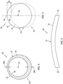
FIG. 4 is a schematic illustration depicting wall thickness variation in a shaft. -
FIG. 5 is a schematic illustration depicting shaft runout. -
FIG. 6 is a schematic illustration depicting a bow in a shaft. -
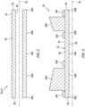
FIGS. 7A and 7B are schematic cross sectional illustrations depicting an exemplary sequence for balancing a rotating structure. -
FIG. 8 is a schematic illustration of a balanced rotating structure assembled in an aircraft drive unit. -
FIG. 9 is a schematic cross sectional illustration of a gas turbine engine. -
FIG. 1 is a flow diagram of amethod 1000 for manufacturing a rotating structure 20 (e.g., seeFIGS. 2 and 3 ) for an apparatus such as, but not limited to, an aircraft drive unit. The term "manufacturing" herein may describe a method for forming therotating structure 20; e.g., creating a brand new rotating structure. The term "manufacturing" may also or alternatively describe a method for repairing therotating structure 20; e.g., restoring one or more features of a previously formed rotating structure to brand new condition, similar to brand new condition or better than brand new condition. Therotating structure 20, for example, may be repaired to fix one or more defects (e.g., cracks, wear and/or other damage) imparted during previous use of therotating structure 20. Therotating structure 20 may also or alternatively be repaired to fix one or more defects imparted during the initial formation of therotating structure 20. However, for ease of description, themanufacturing method 1000 may be described below with respect to the initial forming of therotating structure 20. - The aircraft drive unit may be configured as a thermal engine, a hybrid engine, an electric motor or any other device capable of driving rotation of a mechanical load. This mechanical load may be or include a ducted or unducted bladed rotor and/or a generator rotor. Examples of the bladed rotor include, but are not limited to, a fan rotor, a propeller rotor, a compressor rotor and a helicopter (e.g., main) rotor. Examples of the thermal engine include, but are not limited to, a gas turbine engine, a reciprocating internal combustion piston engine and a rotary internal combustion engine.
- The
rotating structure 20 may be configured as any component or assemblage of components within and/or coupled to the apparatus; e.g., the aircraft drive unit. Therotating structure 20 ofFIG. 2 , for example, is configured as ashaft 22; e.g., a driveshaft, a coupling shaft, an input shaft, an output shaft, etc. Thisshaft 22 extends axially along arotational axis 24 of therotating structure 20 and itsshaft 22 between and to afirst end 26 of theshaft 22 and asecond end 28 of theshaft 22. Here, the shaftfirst end 26 is also a first end of therotating structure 20, and the shaftsecond end 28 is also a second end of therotating structure 20. Theshaft 22 extends radially from aninner side 30 of theshaft 22 to anouter side 32 of theshaft 22. Here, the shaftinner side 30 is also an inner side of the rotatingstructure 20, and the shaftouter side 32 is also an outer side of the rotatingstructure 20. Theshaft 22 extends circumferentially about (e.g., completely around) therotational axis 24, which provides theshaft 22 with a tubular full-hoop body. While the rotatingstructure 20 ofFIG. 2 (e.g., only) includes theshaft 22, the present disclosure is not limited to such an exemplary rotating structure configuration. The rotatingstructure 20 ofFIG. 3 , for example, also includes one or moreother components 34A-F (generally referred to as "34") (schematically shown) mounted on and/or otherwise (e.g., directly or indirectly) rotatably coupled with theshaft 22. Examples of these other components 34 include, but are not limited to, a bladed rotor (e.g., a propulsor rotor, a compressor rotor, a turbine rotor, etc.), a spacer, a bearing race, a seal element, a seal land, a gear of a geartrain, another shaft, etc. - In
step 1002, the rotatingstructure 20 is provided. For ease of description, themanufacturing method 1000 may be described below with respect to the rotatingstructure 20 ofFIG. 2 . However, thismanufacturing method 1000 may alternatively be performed for the rotatingstructure 20 ofFIG. 3 or any other rotating structure for the aircraft drive unit or any other apparatus with a rotating structure. - In
step 1004, one or more physical parameters of the rotatingstructure 20 are measured or otherwise determined. The term "physical parameter" herein may describe a measured value of a geometric feature of the rotatingstructure 20. - Referring to
FIG. 4 , the physical parameters may include one or more measurements of a thickness of a wall 36 (e.g., a tubular sidewall) of theshaft 22. These wall thickness measurements may include aminimum wall thickness 38A of theshaft 22 and/or amaximum wall thickness 38B of theshaft 22. Each of the wall thicknesses 38A, 38B (generally referred to as "38") is a measure of a distance from the shaftinner side 30 to the shaftouter side 32. This wall thickness 38 may be measured in a radial direction and/or perpendicular to one or more of the shaft sides 30, 32 and/or perpendicular to therotational axis 24. InFIG. 4 , the wall thicknesses 38 are measured at a common (the same)axial location 40 along theshaft 22. However, referring toFIG. 2 (see alsoFIG. 3 ), one or more of these wall thicknesses 38 may also be measured or otherwise determined at one or more additional locations (e.g., 40A-E; generally referred to as "40") along an axial length of theshaft 22. Typically, the greater the number of theaxial locations 40 for which the wall thickness(es) 38 are determined, the greater the accuracy of a rotating structure balancing described below. - Referring to
FIG. 5 , the physical parameters may also or alternatively include a measurement of a runout of theshaft 22. The term "shaft runout" herein may describe a rotational eccentricity of theshaft 22 from therotational axis 24. The shaft runout may be measured as a difference 42 (e.g., a dimensional distance) between alow point 44 on the shaftouter side 32 and ahigh point 46 on the shaftouter side 32 during rotation of the rotatingstructure 20. The shaft runout may be affected by shaft concentricity and/or shaft ovality, one or both of which may be measured to determine the shaft runout. The shaft runout may be caused by bowing of theshaft 22; e.g., seeFIG. 6 . Referring toFIG. 2 (see alsoFIG. 3 ), the shaft runout may be measured or otherwise determined at one or more locations (e.g., 40A-E) along the axial length of theshaft 22. Typically, the greater the number of theaxial locations 40 for which the shaft runout is determined, the greater the accuracy of the rotating structure balancing described below. - The physical parameters may be measured or otherwise determined using various techniques. One or more or all of the physical parameters, for example, may be (e.g., directly) measured using manual measurement tools such as, but not limited to, calipers, a runout gauge, etc. One or more or all of the physical parameters may also or alternatively be (e.g., directly) measured using electronic measurement tools such as, but not limited to, 3D metrology, an ultrasonic measurement system, a computed tomography (CT) measurement system, a structured light (e.g., white light) measurement system, an x-ray measurement system, etc. One or more or all of the physical parameters may also or alternatively be (e.g., indirectly) measured by first measuring one or more other parameters and then processing those parameter(s) to determine the physical parameters of interest. The present disclosure, however, is not limited to the foregoing exemplary measurement techniques.
- In
step 1006, the rotatingstructure 20 is modeled to determine a balancing correction. The rotatingstructure 20, for example, may be computationally modeled (e.g., modeled using a computer system) using the physical parameters measured during thestep 1004. The rotatingstructure 20 may also be computationally modeled using (e.g., known or predetermined) data from a design specification for the rotatingstructure 20; e.g., a design specification for theshaft 22. The physical parameters and the specification data may be processed to determine if the rotatingstructure 20 and itsshaft 22 are rotationally unbalanced. And, if the rotatingstructure 20 and itsshaft 22 are rotationally unbalanced, the physical parameters and the specification data may be processed to determine the balancing correction for the rotatingstructure 20 and itsshaft 22. This balancing correction is indicative of an alteration which can be made to the rotatingstructure 20 and itsshaft 22 to rotationally balance the rotatingstructure 20 and itsshaft 22 about therotational axis 24; e.g., locate a center of gravity of the rotatingstructure 20 and itsshaft 22 on therotational axis 24. The balancing correction, for example, may be indicative of how much mass to add to the rotatingstructure 20 and itsshaft 22, and how to orient (e.g., circumferentially clock) that mass with the rotatingstructure 20 and itsshaft 22. The balancing correction may alternatively be indicative of how much mass to remove from the rotatingstructure 20 and itsshaft 22, and where to remove the mass with respective to the rotatingstructure 20 and itsshaft 22. - The modeling of the rotating
structure 20 and itsshaft 22 may be analytically performed for one or more rotational speeds about therotational axis 24. One or more of these rotational speeds may correspond to a rotational speed that the rotatingstructure 20 and itsshaft 22 will rotate at during a mode of apparatus (e.g., aircraft drive unit) operation. Examples of these modes include, but are not limited to, full power (e.g., power for aircraft takeoff), intermediate power (e.g., power for aircraft cruise) and low power (e.g., power for aircraft landing). By modeling the rotatingstructure 20 and itsshaft 22 at such exemplary rotational speed(s), the modeling may take into consideration dynamic rotational response(s) of the rotatingstructure 20 and itsshaft 22; e.g., vibrations, natural frequency, etc. Of course, in other embodiments, one or more of the rotational speeds may correspond to a rotational speed below the rotating structure operating speed. - Where the dynamic rotational responses are modeled for multiple rotational speeds, the balancing correction may be provided to improve balancing for each of the rotational speeds. The balancing correction, for example, may provide a balance (e.g., middle ground) between balancing for a first rotational speed and balancing for a second rotational speed.
- In
step 1008, the rotatingstructure 20 is modified based on the determined balancing correction. For example, material (mass) may be added to and/or removed from the rotatingstructure 20 and itsshaft 22 according to the balancing correction determined during thestep 1006 to rotationally balance the rotatingstructure 20. For example, referring toFIG. 7A , a balancing mass 48 (e.g., a balancing cup) may be modified according to the balancing correction. For example, some or all material from one or more select features 50 (e.g., tabs, arms, spokes, etc.) on the balancingmass 48 may be removed (see dashed lines). Referring toFIG. 7B , this modified balancingmass 48 may then be mounted with the rotatingstructure 20 and itsshaft 22. The modified balancingmass 48, for example, may be inserted into aninner bore 52 of theshaft 22 and attached (e.g., via a compression fit, bonding, a mechanical connection, etc.) to theshaft wall 36. The present disclosure, however, is not limited to the foregoing exemplary balancing mass. - By balancing the rotating
structure 20 and itsshaft 22 using the computational model, the rotatingstructure 20 and itsshaft 22 may be balanced for the operating conditions they will experience during actual operation. By contrast, a typical mechanical balancing device rotates a rotating structure at relatively low speeds - compared to operating speeds of an aircraft engine, for example. However, a dynamic response of a rotating structure at low speeds may be different than a dynamic response of the rotating structure at higher speeds. Furthermore, rotating structure supports (e.g., bearings, etc.) may be located at different locations in the mechanical balancing device than in the actual aircraft drive unit. While a rotating structure may alternatively be mechanically balanced in a test rig (e.g., a test engine) to more accurately simulate operating conditions, test rigs may be expensive and time consuming to operate. Furthermore, even when using a test rig, the rotating structure may be supported at alternative locations and/or not be coupled to all its components; e.g., bladed rotors, etc. A test rig may also not be able to account for certain rotor dynamic instabilities and/or unrepresented boundary conditions. - In step 1010, the rotating
structure 20 is assembled with the apparatus. The rotatingstructure 20 ofFIG. 8 , for example, may be assembled into the aircraft drive unit (e.g., 54), or coupled to the aircraft drive unit. Where the rotatingstructure 20 is configured as theshaft 22, various additional components may be mounted to and/or otherwise coupled to the rotatingstructure 20 before and/or after being assembled with theaircraft drive unit 54. -
FIG. 9 illustrates an exemplary embodiment of the apparatus (e.g., the aircraft drive unit) configured as agas turbine engine 56, whichgas turbine engine 56 may include the balanced rotating structure 20 (e.g., seeFIGS. 2 and 3 ). The balancedrotating structure 20, of course, may alternatively be configured for and included in various types of engines other than the exemplarygas turbine engine 56 ofFIG. 9 as described above. Referring again toFIG. 9 , thegas turbine engine 56 extends axially along an axial centerline 58 (e.g., the rotational axis 24) between anupstream airflow inlet 60 and a downstream airflow exhaust 62. Thegas turbine engine 56 includes afan section 64, acompressor section 65, acombustor section 66 and aturbine section 67. Theturbine section 67 includes a high pressure turbine (HPT)section 67A and a low pressure turbine (LPT)section 67B; e.g., a power turbine section. - The engine sections 64-67B are arranged sequentially along the axial centerline 58 within an
engine housing 70. Thisengine housing 70 includes an inner case 72 (e.g., a core case) and an outer case 74 (e.g., a fan case). Theinner case 72 may house one or more of the engine sections 65-67B; e.g., a core of thegas turbine engine 56. Theouter case 74 may house at least thefan section 64. - Each of the
engine sections - The
fan rotor 76 is connected to and driven by theLPT rotor 79 through alow speed shaft 82. At least (or only) theengine members speed rotating structure 84. Thecompressor rotor 77 is connected to and driven by theHPT rotor 78 through ahigh speed shaft 86. At least (or only) theengine members structures 84, 88 and theirshafts engine housing 70 by at least one stationary structure such as, for example, an annular support strut. The rotatingstructure 20 may be configured as, or may be included in, any one of therotating structures 84, 88 or any one of theshafts - During operation, air enters the
gas turbine engine 56 through theairflow inlet 60. This air is directed through thefan section 64 and into acore flowpath 90 and abypass flowpath 92. Thecore flowpath 90 extends sequentially through the engine sections 65-67B; e.g., the engine core. The air within thecore flowpath 90 may be referred to as "core air". Thebypass flowpath 92 extends through a bypass duct, which bypasses the engine core. The air within thebypass flowpath 92 may be referred to as "bypass air". - The core air is compressed by the
compressor rotor 77 and directed into acombustion chamber 94 of acombustor 96 in thecombustor section 66. Fuel is injected into thecombustion chamber 94 and mixed with the compressed core air to provide a fuel-air mixture. This fuel-air mixture is ignited and combustion products thereof flow through and sequentially cause theHPT rotor 78 and theLPT rotor 79 to rotate. The rotation of theHPT rotor 78 drives rotation of thecompressor rotor 77 and, thus, compression of the air received from a core airflow inlet. The rotation of theLPT rotor 79 drives rotation of thefan rotor 76, which propels bypass air through and out of thebypass flowpath 92. The propulsion of the bypass air may account for a majority of thrust generated by thegas turbine engine 56. - The
gas turbine engine 56 is described above as a turbofan gas turbine engine. The present disclosure, however, is not limited to such an exemplary gas turbine engine. Thegas turbine engine 56, for example, may alternatively be configured as a turboprop gas turbine engine, a turboshaft gas turbine engine, a turbojet gas turbine engine, a pusher fan gas turbine engine, a propfan gas turbine engine, an auxiliary power unit (APU) gas turbine engine or any other type of gas turbine engine or aircraft engine. - While various embodiments of the present disclosure have been described, it will be apparent to those of ordinary skill in the art that many more embodiments and implementations are possible within the scope of the disclosure. For example, the present disclosure as described herein includes several aspects and embodiments that include particular features. Although these features may be described individually, it is within the scope of the present disclosure that some or all of these features may be combined with any one of the aspects and remain within the scope of the disclosure. Accordingly, the present disclosure is not to be restricted except in light of the attached claims and their equivalents.
Claims (15)
- A method for manufacturing, comprising:providing a rotating structure (20) rotatable about an axis (24), the rotating structure (20) comprising a shaft (22);measuring a plurality of physical parameters of the shaft (22);computationally modeling the rotating structure (20) using the plurality of physical parameters to determine a correction to balance rotation of the rotating structure (20) about the axis (24); andphysically altering the rotating structure (20) according to the correction.
- The method of claim 1, wherein one of the plurality of physical parameters is a first runout measurement of the shaft (22) at a first axial location (40A ... 40E) along the shaft (22).
- The method of claim 2, wherein another one of the plurality of physical parameters is a second runout measurement of the shaft (22) at a second axial location (40A ... 40E) along the shaft (22).
- The method of any preceding claim, wherein one of the plurality of physical parameters is a first wall thickness (38) measurement of the shaft (22) at a or the first axial location (40A ... 40E) along the shaft (22).
- The method of claim 4, wherein:the first wall thickness (38) measurement is a minimum wall thickness (38A) measurement of the shaft (22) at the first axial location (40A ... 40E) along the shaft (22); andanother one of the plurality of physical parameters is a maximum wall thickness (38B) measurement of the shaft (22) at the first axial location (40A ... 40E) along the shaft (22).
- The method of claim 4 or 5, wherein another one of the plurality of physical parameters is a second wall thickness (38) measurement of the shaft (22) at a second axial location (40A ... 40E) along the shaft (22).
- The method of any preceding claim, wherein the computationally modeling of the rotating structure (20) comprises modeling a dynamic rotational response of the rotating structure (20) using the plurality of physical parameters to determine the correction.
- The method of claim 7, wherein:the rotating structure (20) is configured for an aircraft drive unit (54); andthe dynamic rotational response of the rotating structure (20) is modeled at an operating speed of the rotating structure (20) during one or more modes of operation of the aircraft drive unit (54).
- The method of any preceding claim, wherein the physically altering of the rotating structure (20) comprises removing material from the rotating structure (20).
- The method of any preceding claim, wherein the physically altering of the rotating structure (20) comprises adding material to the rotating structure (20).
- The method of any preceding claim, wherein the physically altering of the rotating structure (20) comprises:providing a balancing mass (48); andinserting the balancing mass (48) into a bore of the shaft (22) and attaching the balancing mass (48) to the shaft (22).
- The method of any preceding claim, wherein:the rotating structure (20) is configured for a motor or an engine of an aircraft; and/orwherein:the rotating structure (20) consists of the shaft (22); orthe rotating structure (20) further comprises a bladed rotor (76) and/or a component (34) mounted to the shaft (22).
- The method of any preceding claim, further comprising assembling a balanced rotating structure (20) into an aircraft drive unit (54), wherein the physically altering of the rotating structure (20) provides the balanced rotating structure (20).
- A method for manufacturing, comprisingproviding a rotating structure (20) rotatable about an axis (24), the rotating structure (20) comprising a shaft (22);measuring a minimum wall thickness (38A) measurement of the shaft (22) at one or more locations (40A ... 40E) axially along the shaft (22) to provide minimum wall thickness data;measuring a maximum wall thickness (38B) measurement of the shaft (22) at one or more locations (40A ... 40E) axially along the shaft (22) to provide maximum wall thickness data;measuring a runout measurement of the shaft (22) at one or more locations (40A ... 40E) axially along the shaft (22) to provide runout data; andprocessing the minimum wall thickness data, the maximum wall thickness data and the runout data to determine a correction to balance rotation of the rotating structure (20) about the axis (24); and optionallymodifying the rotating structure (20) according to the correction to provide a balanced rotating structure (20).
- A method for manufacturing, comprising:providing a rotating structure (20) rotatable about an axis (24), the rotating structure (20) comprising a shaft (22) and a component (34) mounted to the shaft (22);measuring a plurality of physical parameters of the rotating structure (20); andmodeling the rotating structure (20) using the plurality of physical parameters to determine a correction to balance rotation of the rotating structure (20) about the axis (24); and optionallyphysically altering the rotating structure (20) according to the correction to provide a balanced rotating structure (20).
Applications Claiming Priority (1)
| Application Number | Priority Date | Filing Date | Title |
|---|---|---|---|
| US18/094,189 US20240230448A1 (en) | 2023-01-06 | 2023-01-06 | Computationally balancing a rotating structure |
Publications (1)
| Publication Number | Publication Date |
|---|---|
| EP4400693A1 true EP4400693A1 (en) | 2024-07-17 |
Family
ID=89535806
Family Applications (1)
| Application Number | Title | Priority Date | Filing Date |
|---|---|---|---|
| EP24150782.1A Pending EP4400693A1 (en) | 2023-01-06 | 2024-01-08 | Computationally balancing a rotating structure |
Country Status (3)
| Country | Link |
|---|---|
| US (1) | US20240230448A1 (en) |
| EP (1) | EP4400693A1 (en) |
| CA (1) | CA3225465A1 (en) |
Citations (4)
| Publication number | Priority date | Publication date | Assignee | Title |
|---|---|---|---|---|
| US20080027686A1 (en) * | 2006-07-31 | 2008-01-31 | Mollmann Daniel E | Methods and systems for assembling rotatable machines |
| EP2184595A1 (en) * | 2007-08-01 | 2010-05-12 | Komatsu Machinery Corp. | Treating apparatus, center-hole working system, center-hole position deciding program, and center-hole position deciding method |
| DE102016203647A1 (en) * | 2016-03-07 | 2017-09-07 | MTU Aero Engines AG | Method for connecting at least two rotor elements of a turbomachine |
| DE102019113500A1 (en) * | 2019-05-21 | 2020-11-26 | Brandenburgische Technische Universität Cottbus-Senftenberg | PROCEDURE FOR DIGITAL BALANCING OF A ROTOR AND A ROTOR |
Family Cites Families (1)
| Publication number | Priority date | Publication date | Assignee | Title |
|---|---|---|---|---|
| US4177692A (en) * | 1977-11-25 | 1979-12-11 | General Motors Corporation | Shaft balancing |
-
2023
- 2023-01-06 US US18/094,189 patent/US20240230448A1/en active Pending
-
2024
- 2024-01-05 CA CA3225465A patent/CA3225465A1/en active Pending
- 2024-01-08 EP EP24150782.1A patent/EP4400693A1/en active Pending
Patent Citations (4)
| Publication number | Priority date | Publication date | Assignee | Title |
|---|---|---|---|---|
| US20080027686A1 (en) * | 2006-07-31 | 2008-01-31 | Mollmann Daniel E | Methods and systems for assembling rotatable machines |
| EP2184595A1 (en) * | 2007-08-01 | 2010-05-12 | Komatsu Machinery Corp. | Treating apparatus, center-hole working system, center-hole position deciding program, and center-hole position deciding method |
| DE102016203647A1 (en) * | 2016-03-07 | 2017-09-07 | MTU Aero Engines AG | Method for connecting at least two rotor elements of a turbomachine |
| DE102019113500A1 (en) * | 2019-05-21 | 2020-11-26 | Brandenburgische Technische Universität Cottbus-Senftenberg | PROCEDURE FOR DIGITAL BALANCING OF A ROTOR AND A ROTOR |
Also Published As
| Publication number | Publication date |
|---|---|
| CA3225465A1 (en) | 2025-04-09 |
| US20240230448A1 (en) | 2024-07-11 |
Similar Documents
| Publication | Publication Date | Title |
|---|---|---|
| EP3628820B1 (en) | Gas turbine engine system cooldown | |
| EP3361229B1 (en) | System and method for blade health monitoring | |
| WO2019241538A1 (en) | Inspection tool and method | |
| EP4273369B1 (en) | Determining a moment weight of a component based on measured surface geometry/solid model of the component | |
| US10968769B2 (en) | Method and system for calibrating an engine core by determining power rating data of the engine core | |
| US10247003B2 (en) | Balanced rotating component for a gas powered engine | |
| EP3287674A1 (en) | Floating, non-contact seal with offset building clearance for load imbalance | |
| CN203130170U (en) | Low-pressure rotor autorotation tool used for borescope inspection of engine of civil aircraft | |
| US20200232883A1 (en) | Detecting an object impact event | |
| US11041396B2 (en) | Axial-radial cooling slots on inner air seal | |
| EP3663516B1 (en) | Component inspection using measured and theoretical moment weights | |
| US20240230448A1 (en) | Computationally balancing a rotating structure | |
| US20180216466A1 (en) | Methods and systems for rotating component balancing | |
| EP3564481A1 (en) | Modular rotor balancing | |
| US11098604B2 (en) | Radial-axial cooling slots | |
| EP3748134B1 (en) | Vane airfoil shapes for embedded members | |
| US20240385234A1 (en) | Identifying fault in torque signal / torque sensor for aircraft system | |
| EP2009451A2 (en) | Synchronous signal generator for trim balancing of jet engine | |
| US11867075B2 (en) | Radial outward bearing support for a rotating structure of a turbine engine | |
| CN119435203A (en) | Gas turbine engine having a sensor assembly for detecting torsional vibrations | |
| US20240159608A1 (en) | System and method for determining torque in a turbomachine | |
| US10836499B2 (en) | Turbine engine with single wall cantilevered architecture | |
| CA3230861A1 (en) | Test blade for gas turbine engine and method of making | |
| US12286893B2 (en) | Apparatus and method for partially bladed rotor test | |
| EP4524372A1 (en) | Stator with adjustable radial height |
Legal Events
| Date | Code | Title | Description |
|---|---|---|---|
| PUAI | Public reference made under article 153(3) epc to a published international application that has entered the european phase |
Free format text: ORIGINAL CODE: 0009012 |
|
| STAA | Information on the status of an ep patent application or granted ep patent |
Free format text: STATUS: THE APPLICATION HAS BEEN PUBLISHED |
|
| AK | Designated contracting states |
Kind code of ref document: A1 Designated state(s): AL AT BE BG CH CY CZ DE DK EE ES FI FR GB GR HR HU IE IS IT LI LT LU LV MC ME MK MT NL NO PL PT RO RS SE SI SK SM TR |
|
| STAA | Information on the status of an ep patent application or granted ep patent |
Free format text: STATUS: REQUEST FOR EXAMINATION WAS MADE |
|
| 17P | Request for examination filed |
Effective date: 20250117 |
|
| STAA | Information on the status of an ep patent application or granted ep patent |
Free format text: STATUS: EXAMINATION IS IN PROGRESS |
|
| 17Q | First examination report despatched |
Effective date: 20251106 |