EP4400691A2 - Setting tool for a liner hanger - Google Patents
Setting tool for a liner hanger Download PDFInfo
- Publication number
- EP4400691A2 EP4400691A2 EP24180018.4A EP24180018A EP4400691A2 EP 4400691 A2 EP4400691 A2 EP 4400691A2 EP 24180018 A EP24180018 A EP 24180018A EP 4400691 A2 EP4400691 A2 EP 4400691A2
- Authority
- EP
- European Patent Office
- Prior art keywords
- sleeve
- liner hanger
- setting tool
- central bore
- liner
- Prior art date
- Legal status (The legal status is an assumption and is not a legal conclusion. Google has not performed a legal analysis and makes no representation as to the accuracy of the status listed.)
- Granted
Links
Images








Classifications
-
- E—FIXED CONSTRUCTIONS
- E21—EARTH OR ROCK DRILLING; MINING
- E21B—EARTH OR ROCK DRILLING; OBTAINING OIL, GAS, WATER, SOLUBLE OR MELTABLE MATERIALS OR A SLURRY OF MINERALS FROM WELLS
- E21B23/00—Apparatus for displacing, setting, locking, releasing or removing tools, packers or the like in boreholes or wells
- E21B23/04—Apparatus for displacing, setting, locking, releasing or removing tools, packers or the like in boreholes or wells operated by fluid means, e.g. actuated by explosion
- E21B23/0412—Apparatus for displacing, setting, locking, releasing or removing tools, packers or the like in boreholes or wells operated by fluid means, e.g. actuated by explosion characterised by pressure chambers, e.g. vacuum chambers
-
- E—FIXED CONSTRUCTIONS
- E21—EARTH OR ROCK DRILLING; MINING
- E21B—EARTH OR ROCK DRILLING; OBTAINING OIL, GAS, WATER, SOLUBLE OR MELTABLE MATERIALS OR A SLURRY OF MINERALS FROM WELLS
- E21B23/00—Apparatus for displacing, setting, locking, releasing or removing tools, packers or the like in boreholes or wells
- E21B23/01—Apparatus for displacing, setting, locking, releasing or removing tools, packers or the like in boreholes or wells for anchoring the tools or the like
-
- E—FIXED CONSTRUCTIONS
- E21—EARTH OR ROCK DRILLING; MINING
- E21B—EARTH OR ROCK DRILLING; OBTAINING OIL, GAS, WATER, SOLUBLE OR MELTABLE MATERIALS OR A SLURRY OF MINERALS FROM WELLS
- E21B23/00—Apparatus for displacing, setting, locking, releasing or removing tools, packers or the like in boreholes or wells
- E21B23/06—Apparatus for displacing, setting, locking, releasing or removing tools, packers or the like in boreholes or wells for setting packers
-
- E—FIXED CONSTRUCTIONS
- E21—EARTH OR ROCK DRILLING; MINING
- E21B—EARTH OR ROCK DRILLING; OBTAINING OIL, GAS, WATER, SOLUBLE OR MELTABLE MATERIALS OR A SLURRY OF MINERALS FROM WELLS
- E21B33/00—Sealing or packing boreholes or wells
- E21B33/02—Surface sealing or packing
- E21B33/03—Well heads; Setting-up thereof
- E21B33/04—Casing heads; Suspending casings or tubings in well heads
-
- E—FIXED CONSTRUCTIONS
- E21—EARTH OR ROCK DRILLING; MINING
- E21B—EARTH OR ROCK DRILLING; OBTAINING OIL, GAS, WATER, SOLUBLE OR MELTABLE MATERIALS OR A SLURRY OF MINERALS FROM WELLS
- E21B33/00—Sealing or packing boreholes or wells
- E21B33/10—Sealing or packing boreholes or wells in the borehole
- E21B33/12—Packers; Plugs
- E21B33/128—Packers; Plugs with a member expanded radially by axial pressure
-
- E—FIXED CONSTRUCTIONS
- E21—EARTH OR ROCK DRILLING; MINING
- E21B—EARTH OR ROCK DRILLING; OBTAINING OIL, GAS, WATER, SOLUBLE OR MELTABLE MATERIALS OR A SLURRY OF MINERALS FROM WELLS
- E21B33/00—Sealing or packing boreholes or wells
- E21B33/10—Sealing or packing boreholes or wells in the borehole
- E21B33/13—Methods or devices for cementing, for plugging holes, crevices or the like
- E21B33/14—Methods or devices for cementing, for plugging holes, crevices or the like for cementing casings into boreholes
-
- E—FIXED CONSTRUCTIONS
- E21—EARTH OR ROCK DRILLING; MINING
- E21B—EARTH OR ROCK DRILLING; OBTAINING OIL, GAS, WATER, SOLUBLE OR MELTABLE MATERIALS OR A SLURRY OF MINERALS FROM WELLS
- E21B34/00—Valve arrangements for boreholes or wells
- E21B34/06—Valve arrangements for boreholes or wells in wells
- E21B34/063—Valve or closure with destructible element, e.g. frangible disc
-
- E—FIXED CONSTRUCTIONS
- E21—EARTH OR ROCK DRILLING; MINING
- E21B—EARTH OR ROCK DRILLING; OBTAINING OIL, GAS, WATER, SOLUBLE OR MELTABLE MATERIALS OR A SLURRY OF MINERALS FROM WELLS
- E21B34/00—Valve arrangements for boreholes or wells
- E21B34/06—Valve arrangements for boreholes or wells in wells
- E21B34/10—Valve arrangements for boreholes or wells in wells operated by control fluid supplied from outside the borehole
- E21B34/102—Valve arrangements for boreholes or wells in wells operated by control fluid supplied from outside the borehole with means for locking the closing element in open or closed position
- E21B34/103—Valve arrangements for boreholes or wells in wells operated by control fluid supplied from outside the borehole with means for locking the closing element in open or closed position with a shear pin
-
- E—FIXED CONSTRUCTIONS
- E21—EARTH OR ROCK DRILLING; MINING
- E21B—EARTH OR ROCK DRILLING; OBTAINING OIL, GAS, WATER, SOLUBLE OR MELTABLE MATERIALS OR A SLURRY OF MINERALS FROM WELLS
- E21B34/00—Valve arrangements for boreholes or wells
- E21B34/06—Valve arrangements for boreholes or wells in wells
- E21B34/14—Valve arrangements for boreholes or wells in wells operated by movement of tools, e.g. sleeve valves operated by pistons or wire line tools
- E21B34/142—Valve arrangements for boreholes or wells in wells operated by movement of tools, e.g. sleeve valves operated by pistons or wire line tools unsupported or free-falling elements, e.g. balls, plugs, darts or pistons
-
- E—FIXED CONSTRUCTIONS
- E21—EARTH OR ROCK DRILLING; MINING
- E21B—EARTH OR ROCK DRILLING; OBTAINING OIL, GAS, WATER, SOLUBLE OR MELTABLE MATERIALS OR A SLURRY OF MINERALS FROM WELLS
- E21B43/00—Methods or apparatus for obtaining oil, gas, water, soluble or meltable materials or a slurry of minerals from wells
- E21B43/02—Subsoil filtering
- E21B43/10—Setting of casings, screens, liners or the like in wells
-
- E—FIXED CONSTRUCTIONS
- E21—EARTH OR ROCK DRILLING; MINING
- E21B—EARTH OR ROCK DRILLING; OBTAINING OIL, GAS, WATER, SOLUBLE OR MELTABLE MATERIALS OR A SLURRY OF MINERALS FROM WELLS
- E21B2200/00—Special features related to earth drilling for obtaining oil, gas or water
- E21B2200/06—Sleeve valves
Definitions
- Embodiments of the present disclosure generally relate to a setting tool for actuating a liner hanger.
- Liner hangers are used to suspend a liner from another tubular string in a wellbore.
- Conventional hydraulic liner hangers are actuated in response to pressure above a threshold to set slips.
- an increase in fluid circulation through the liner string may be necessary to facilitate moving the liner string through the deviations and/or turns of the wellbore.
- the increase in fluid circulation in the liner string may inadvertently actuate the liner hanger in the wellbore above the intended setting location. Unintended setting of the liner hanger results in the need to remove the liner string and to conduct a subsequent wellbore operation.
- the present disclosure generally to a setting tool for a liner hanger and a methods for completing downhole operations.
- a setting tool for a downhole tool includes a tubular housing having a central bore.
- the setting tool further includes a first seal and a second seal disposed about an exterior of the tubular housing.
- the setting tool further includes a first port formed through the tubular housing and disposed between the first seal and the second seal.
- the setting tool further includes a first sleeve disposed in the central bore and movable from a closed position to an open position, the first sleeve having a seat.
- the setting tool further includes at least one first shearable member configured to releasably attach the first sleeve to the tubular housing in the closed position.
- the setting tool further includes a fluid bypass disposed in the tubular housing and configured to allow fluid communication around the first seal and the second seal. The central bore and the first port are in fluid communication when the first sleeve is in the open position.
- a liner string includes a liner hanger assembly and a liner hanger deployment assembly.
- the liner hanger assembly includes a liner hanger.
- the liner hanger includes a plurality of slips and a liner hanger actuation assembly configured to set the plurality of slips.
- the liner hanger deployment assembly is disposed within the liner hanger assembly.
- the liner hanger deployment assembly includes a setting tool configured to selectively allow fluid communication between a central bore of the setting tool and the liner hanger actuation assembly.
- a method of conducting a wellbore operation includes deploying a liner string into a wellbore to a setting depth.
- the liner string includes a liner hanger assembly including a liner hanger with an actuation assembly, and a liner hanger deployment assembly attached to the liner hanger assembly and including a setting tool, wherein the setting tool is configured to isolate the actuation assembly from fluid communication with a central bore of the setting tool.
- the method further includes actuating the setting tool to allow fluid communication between the central bore and the actuation assembly.
- the method further includes actuating the liner hanger.
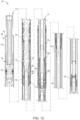
- FIGs 1A-1C illustrate a liner string 100.
- the liner string 100 includes a liner hanger deployment assembly (LHDA) 110, as shown in Figure 1A , and a liner hanger assembly (LHA) 150, as shown in Figure 1B .
- the LHDA 110 may include a packoff 112, a packer actuator 120, a running tool 130, a setting tool 200, and a plug assembly 140.
- the LHA 150 may include a polished bore receptacle (PBR) 160, threads 170, a packer 180, a liner hanger 300, and a liner 190.
- the LHA 150 may also include a landing collar (not shown), a float collar (not shown), and float shoe (not shown) at a lower end.
- Figure 1C illustrates the LHDA 110 disposed within the LHA 150.
- An annulus 101 is between the LHDA 110 and the LHA 150.
- the LHDA 110 is disposed in the bore 152 and releasably attached to the LHA 150. As shown in Figure 1C , the LHDA 110 is attached to the LHA 150 via the engagement of threads 132 of the running tool 130 with the threads 170 during run-in. The LHDA 110 may be released from the LHA 150 downhole, such as by unthreading the threaded connection between threads 132 and 170.
- the setting tool 200 is disposed in the liner hanger 300 during run-in of the liner string 100. Circulation through the liner string 100 may be increased during run-in to facilitate moving the liner string 100 through deviations or turns in the wellbore.
- the setting tool 200 prevents premature actuation of the liner hanger 300 during run-in of the liner string 100. Once run-in of the liner string 100 is complete, the setting tool 200 is actuated to allow the actuation of the liner hanger 300 in response to fluid pressure. In some embodiments, the setting tool 200 can be actuated prior to the completion of run-in once the liner string 100 is close to the setting depth. After actuation of the setting tool 200, the liner hanger 300 is actuated in response to reaching a pressure threshold.
- the packer 180 may include a tubular mandrel 181, a packing element 182, one or more shearable members 183, and an actuation sleeve assembly 184.
- the actuation sleeve assembly 183 is maintained in an initial position by the one or more shearable members 183.
- the PBR 160 abuts one end of the sleeve actuation assembly 184.
- the actuation sleeve assembly 184 is configured to compress the packing element in response to force applied to the PBR 160 from the packer actuator 120.
- the packer actuator 120 may be similar to the packer actuator disclosed in US Pat. No. 9,322,235 , which is herein incorporated by reference.
- the packer actuator 120 includes a plurality of dogs 122 movable from a retracted position to an extended position. The dogs 122 are maintained in the retracted position by engagement with the inner surface of the PBR 160.
- the LHDA 110 can be lifted until the dogs 122 are withdrawn from the PBR 160 to allow the dogs 122 to move to the expanded position.
- the LHDA 110 may then be lowered relative to the LHA 150 until the dogs 122 seat on the top of the PBR 160.
- the actuation sleeve assembly 184 moves relative to the tubular mandrel 181 to compress the packing element 182 until it expands into engagement with the wellbore or casing surrounding the packer 180.
- the packer actuator 120 is used to actuate the mechanically actuated packer 180 to seal the annulus surrounding the LHA 150 by expanding the packing element 182 of the packer 180.
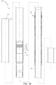
- FIG. 2A illustrates an embodiment of a setting tool 200.
- the setting tool 200 may include a tubular housing 210, a sleeve 220, a first seal 230a, a second seal 230b, one or more ports 240, one or more shearable members 250, and a fluid bypass 260.
- the tubular housing 210 defines a central bore 202.
- the tubular housing 210 may include one or more sections 210a-h connected together, such as by threaded couplings and/or fasteners. Seals 211 may be placed between the interconnecting tubular housing sections 21 0a-h to prevent fluid in the central bore 202 from leaking to the environment outside of the setting tool 200, and vice versa.
- the seals 211 maintain pressure integrity of the setting tool 200.
- the tubular housing 210 has a connection at each end, such as a pin 201a and a box 201b.
- the first seal 230a and the second seal 230b are disposed about the exterior of the tubular housing 210.
- the first seal 230a and the second seal 230b are configured to sealingly engage with an inner surface of the bore 152 of the LHA 150 and to straddle a port 340 of the liner hanger 300.
- the first and second seals 230a,b may sealing engage with the inner surface of a tubular mandrel 310 of the liner hanger 300.
- the fluid bypass 260 is disposed in the tubular housing 210.
- the fluid bypass extends from one or more openings 262a to one or more openings 262b.
- the fluid bypass 260 allows fluid communication above and below the first and second seals 230a,b when the seals 230a,b are sealingly engaged with the inner surface of the bore 152 of the LHA 150, such as the inner surface of the tubular mandrel 310 (see Figure 4A ).
- the fluid bypass 260 allows for fluid communication around the seals 230a,b.
- the fluid bypass 260 is not in fluid communication with the one or more ports 240.
- Figures 2B-2E show cross sections of the setting tool 200 to better illustrate the fluid bypass 260 and setting tool 200.
- the one or more openings 262a are formed in the tubular housing section 210b.
- the fluid bypass 260 can be formed from a combination of gaps between tubular sections and/or bores present in the tubular sections forming the tubular housing 210.
- one or more gaps 270a may be present between the tubular housing sections 210a and 210c
- one or more gaps 270b may be present between tubular housing sections 210f and 21 0h.
- one or more bores 272a may be formed in the tubular housing section 210d.
- one or more bores 272b may be formed in the tubular housing section 210e.
- the dashed lines in tubular housing section 210d, as shown in Figure 2A illustrate the one or more bores 272a.
- the gaps 270a,b, the bores 272a,b, and the openings 262a,b form the fluid bypass 260.
- fluid may flow between openings 262a,b via the gaps 270a,b and bores 272a,b.
- the number of bores 272a is less than the number of bores 272b, and vice versa.
- the fluid bypass 260 may be a plurality of individual fluid bypasses formed in the tubular housing 210 that are isolated from one another.
- the packoff 112 seals against the inner surface of the LHA 150, such as the inner surface of the packer 180. As a result, a portion 101a of the annulus 101 is bounded by the packoff 112 and the first seal 230a. A portion 101b of the annulus 101 is below the second seal 230b.
- the fluid bypass 260 allows the portion 101a of the annulus 101 between packoff 112 and first seal 230a to be in fluid communication with the portion 101b of the annulus below the second seal 230b. This allows the annulus portion 101a to fill with wellbore fluid during run-in and to equalize pressure with the annulus portion 101b. Without the fluid bypass 260, the annulus portion 101a would be isolated from the wellbore fluids.
- annulus portion 101a was isolated from the wellbore fluids, then a pressure difference between the annulus portion 101a and the annulus surrounding the outside of the LHA 150 would increase with depth, thereby increasing the risk of a collapse of the LHA 150, such as the collapse of the portion of the LHA150 between the first seal 230a and the packoff 112.
- the collapse risk is caused, in part, by the thickness and material of the LHA 150.
- a collapse may prevent the LHDA 110 from being tripped out of the LHA 150, which might require tripping both the LHDA 110 and LHA 150 from the wellbore.
- the fluid bypass 260 alleviates the pressure difference and allows the liner string 100 to be run-in to greater depths.
- the ports 240 Prior to the actuation of the setting tool 200, fluid communication between the central bore 202 and the one or more ports 240 is blocked by the sleeve 220.
- Some of the ports 240 are threaded ports 240t for receiving a shearable member 250 that releasably attaches the sleeve 220 to the tubular housing 210.
- the one or more ports 240 including the threaded ports 240t, are formed through tubular housing 210, such as through tubular housing section 210d. As shown in Figure 2A and 2C , the shearable members 250 are disposed in the threaded ports 240t.
- one or all of the shearable members 250 may be disposed at another location in the tubular housing 210 instead of being disposed in the threaded ports 240t.
- the ports 240, including the threaded ports 240t, are disposed between the first and second seals 230a,b.
- the sleeve 220 is disposed in the central bore 202.
- the sleeve 220 is movable from a closed positon ( Figure 2A ) to an open position ( Figure 4C ).
- the sleeve 220 is releasably attached to the tubular housing 210, such as tubular housing section 210d, by the one or more shearable members 250.
- the shearable members 250 may be threaded into a corresponding hole in the sleeve 220.
- the shearable members 250 may be partially disposed in a groove or recess of the sleeve 220.
- the sleeve 220 In the open position, the shearable members 250 have sheared, and the sleeve 220 has moved relative to the tubular housing 210 to expose the one or more ports 240 to fluid communication with the central bore 202.
- the sleeve 220 may include one or more seals 222 disposed around the sleeve 220 to prevent fluid communication between the central bore 202 and the one or more ports 240 while the sleeve 220 is in the closed position.
- the sleeve 220 includes a seat 224 configured to catch a first object 410, such as a ball or a dart.
- the seat 224 may be coupled to the sleeve 220, such as coupled to one end of the sleeve 220, or the seat 224 may be integrally formed with the sleeve 220.
- a seal 222 may be disposed around the seat 224.
- FIG. 3 illustrates an exemplary liner hanger 300.
- the liner hanger 300 may include the tubular mandrel 310, a slip assembly 320, and a slip actuation assembly 330.
- the tubular mandrel 310 defines a central bore 302 of the liner hanger 300 and includes the port 340.
- the liner hanger 300 can have more than one port 340.
- the slip assembly 320 may include a first abutment member 322 and a plurality of slips 324 configured to ride up one or more ramps 326 coupled to the tubular mandrel 310.
- the slip actuation assembly 330 may include a piston member 331, a second abutment member 332, a sleeve member 333, one or more shearable members 334, and a piston chamber 335 disposed between a first seal 336 and a second seal 337.
- the sleeve member 333 is attached to the tubular mandrel 310, such as by a plurality of fasteners.
- the piston member 331 is attached to the second abutment member 332 at one end.
- the second seal 337 is coupled to the piston member 331.
- the piston member 331 is releasably attached to the sleeve member 333 via the one or more shearable members 334.
- the one or more shearable members 250 may be configured to shear at a lower pressure than the pressure necessary to shear the one or more shearable members 334.
- the first seal 336 is disposed between the tubular mandrel 310 and the piston member 331, and the first seal 336 is affixed to the tubular mandrel 310.
- the piston chamber 335 is in fluid communication with the port 340.
- Figure 4A illustrates the setting tool 200 disposed in the central bore 302 of the liner hanger 300.
- the LHDA 110 is still attached to the LHA 150.
- the seals 230a,b are shown as engaged with the tubular mandrel 310.
- a pressure chamber 400 is disposed between the seals 230a,b when the seals 230a,b are engaged with the inner surface of the bore 152 of the LHA 150.
- the port 340 is disposed between the seals 230a,b such that it is in fluid communication with the pressure chamber 400.
- the pressure chamber 400 is isolated from fluid communication with the central bore 202 via the sleeve 220.
- the pressure chamber 400 is isolated from the annulus portions 101a by the first seal 230a.
- the pressure chamber 400 is isolated from the annulus portion 101b by the second seal 230b.
- the pressure chamber 400 may be at atmospheric pressure, or it may be pressurized to a set pressure.
- the pressure chamber 400, and thus the piston chamber 335, is isolated from fluid communication with the central bore 202 during run-in to avoid inadvertent actuation of the liner hanger 300.
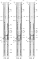
- FIG. 4A-4F An exemplary operation sequence of the liner string 100 including the setting tool 200 and liner hanger 300 is illustrated in Figures 4A-4F .
- the setting tool 200 and the liner hanger 300 are shown disposed in a casing 500.
- the setting tool 200 and liner hanger 300 are at the setting depth in the wellbore.
- the setting tool 200 is ready to be actuated.
- the first object 410 is dropped into the wellbore where it will engage with the seat 224 as shown in Figure 4B .
- pressure is increased above the first object 410 until the one or more shearable members 250 shear and the sleeve 220 moves from the closed position to the open position as shown in Figure 4C .
- the sleeve 220 When the sleeve 220 is in the open position, fluid communication is established between the one or more ports 240 and the port 340.
- the pressure chamber 400 With the pressure chamber 400 no longer isolated from the central bore 202, the pressure chamber 400 may fill with wellbore fluid. The operator may wait a certain period of time to allow the pressure chamber 400 to fill with wellbore fluids. As shown in Figure 4C , pressure may continue to be increased above the first object 410 until the one or more shearable members 334 shear.
- the slip actuation assembly 330 moves the slips 324 up the ramps 326 to the set position.
- the one or more shearable members 250 may be designed to shear at the pressure necessary to shear the one or more shearable members 334.
- a test may be conducted to confirm the liner hanger 300 has been set, such as by pulling or pushing on the liner string 100 from the surface to confirm that the slips 324 are set.
- the LHDA 110 may be released from the LHA 150. In one example, the LHDA 110 is rotated relative to the LHA 150 to unthread the threaded connection between thread 132 and thread 170.
- Release of the LHDA 110 from the LHA 150 may be verified by lifting the LHDA 110 a predetermined distance and checking the weight on a load sensor to confirm that the LHA 150 is no longer attached. Pressure can be increased above the first object 410 until the first object 410 passes through the seat 224 as shown in Figure 4D . The first object 410 will travel downhole, and the first object 410 may engage with or pass through the plug assembly 140 or other wellbore equipment below the seat 224. In some embodiments, the object 140 is removed from the seat 224 prior to releasing the LHDA 110 from the LHA 150.
- a cementation operation may begin.
- a second object 420 such as a cementation dart or a ball, may be dropped into the liner string 100 above the cement.
- the second object 420 travels downhole until it engages the seat 224 as shown in Figure 4E .
- Pressure may be increased above the second object 420, if necessary, to pass the second object through the seat 224.
- the second object 420 may continue to travel through the LHDA 110, and the second object 420 may engage the plug assembly 140 or other wellbore equipment below the seat 224.
- Figure 4F illustrates the setting tool 200 disposed in the liner hanger 300 after the second object 420 has passed through the seat 224. Additional objects may be dropped as necessary to complete the cementation operation.
- the LHDA 110 may be lifted until the dogs 122 are removed from the PBR 160, which results in the dogs 122 moving from the unexpanded position to the expanded position. Then, the LHDA 110 is lowered relative to the LHA 150 until the dogs 122 seat on the top of the PBR 160. Then, force (e.g., weight) can be applied to the LHDA 110 to set the mechanically actuated packer 180 via the dogs 122 seated on the PBR 160. After the packer 180 is set, then the LHDA 110 may be tripped out of the wellbore. In some embodiments, the packer 180 may be set without completing a cementation operation.
- force e.g., weight
- Figure 5A-5C illustrates an alternative setting tool 1200 for use with the liner string 100.
- the setting tool 1200 may be substituted for the setting tool 200 in the LHDA 110.
- the setting tool 1200 has similar components as setting tool 200, and the similar components are identified using similar reference numbers.
- FIG. 5A illustrates setting tool 1200.
- the setting tool 1200 may include a tubular housing 1210, a first sleeve 1220, a second sleeve 1252, a first seal 1230a, a second seal 1230b, one or more first ports 1240, one or more second ports 1242, one or more first shearable members 1250, one or more second shearable members 1254, and a fluid bypass 1260.
- the tubular housing 1210 defines a central bore 1202.
- the tubular housing 1210 may include one or more sections 1210a-h connected together, such as by threaded couplings and/or fasteners.
- Seals 1211 may be placed between the interconnecting tubular housing sections 1210a-h to maintain the sealing and pressure integrity of the setting tool 1200.
- the tubular housing 1210 has a connection each end, such as a pin 1201a a box 1201b.
- the first seal 1230a and the second seal 1230b are disposed about the exterior of the tubular housing 1210.
- the first and second seals 1230a,b are configured to sealing engage with the inner surface of the bore 152 of the LHA 150 and to straddle the port 340 of the liner hanger 300.
- the seals 1230a,b are configured to sealingly engage against the inner surface of the tubular mandrel 310 of the liner hanger 300. While the first and second seals 1230a,b are engaged with the inner surface of the bore 152 of the LHA 150, a pressure chamber 1400 is present between the seals 1230a,b.
- the one or more first ports 1240 are formed through the tubular housing 1210, such as through tubular housing section 1210d. Some of the first ports 1240 are threaded ports 1240t for receiving the one or more first shearable members 1250 that releasably attach the first sleeve 1220 to the tubular housing 1210. As shown in Figure 5A and 5B , the one or more first shearable members 1250 are disposed in the threaded ports 1240t. However, the one or more first shearable members 1250 may be disposed at another location in the tubular housing 1210 instead of being disposed in the threaded ports 1240t. The one or more first ports 1240, including the threaded ports 1240t, are disposed between the first and second seals 1230a,b.
- the first sleeve 1220 is disposed in the central bore 1202.
- the first sleeve 1220 is movable from a closed positon ( Figure 5A ) to an open position ( Figure 6C ).
- the first sleeve 1220 is releasably attached to the tubular housing 1210, such as tubular housing section 1210d, by the one or more first shearable members 1250.
- the first sleeve 1220 includes a seat 1224 configured to catch a first object 1410, such as a ball or a dart.
- the seat 1224 may be coupled to the first sleeve 1220.
- the seat 1224 can be coupled to one end of the first sleeve 1220.
- the seat 1224 may be integrally formed with the first sleeve 1220.
- a plurality of seals 1222 may be disposed around the first sleeve 1220 and the seat 224.
- the second sleeve 1252 is disposed in the central bore 1202 and is releasably attached to the tubular housing 1210, such as being releasably attached to tubular housing section 1210e, when in the open position.
- One or more seals 1228 may be disposed about the second sleeve 1252, and the seals 1228 may straddle the one or more second ports 1242.
- the central bore 1202 is in fluid communication with one or more second ports 1242 formed in the tubular housing 1210.
- the second sleeve 1252 includes one or more ports 1256 that are aligned with the one or more second ports 1242 when the second sleeve 1252 is in the open position.
- the one or more second ports 1242 may be formed in the tubular housing section 1210e and some of the one or more second ports 1242 may be threaded 1242t.
- the one or more second ports 1242, including the threaded ports 1242t, are disposed between the first and second seals 1230a,b.
- the second sleeve 1252 is releasably attached to the tubular housing 1210 via one or more second shearable members 1254.
- the second sleeve 1252 is not pressure balanced.
- a chamber 1280 is disposed between the second sleeve 1252 and the tubular housing 1210.
- the chamber 1280 is isolated from the central bore 1202 and the one or more second ports 1242 via the seals 1228.
- the chamber 1280 may be at atmospheric pressure or the chamber may contain a fluid at a specific pressure, such as 500 psi (approximately 3.45 MPa) for example.
- 500 psi approximately 3.45 MPa
- the pressure differential between the chamber 1280 and the central bore 1202 increases.
- the pressure in the pressure chamber 1400 increases with depth, since the pressure chamber 1400 is in fluid communication with the central bore 1202.
- the pressure in the chamber 1280 and the one or more second shearable members 1254 are configured to actuate the second sleeve 1252 at a desired depth.
- the number, thickness, and material of the one or more second shearable members 1254 and/or the pressure in the chamber 1280 can be adjusted based on the desired depth at which the second sleeve 1252 moves to the closed position.
- the second shearable members 1254 shear due to the pressure difference between the pressure acting on the second sleeve 1252 in the central bore 1202 and the pressure in the chamber 1280.
- the desired depth at which the second sleeve 1252 actuates to move to the closed position is the set depth of the pressure chamber 1400.
- the pressure chamber 1400 is isolated from the central bore 1202, preventing the pressure in the pressure chamber 1400 from continuing to increase.
- flow rate can be used to actuate the second sleeve 1252. Fluid flow above a predetermined rate will be sufficient to increase the pressure in the central bore 1202 to act upon the second sleeve 1252 to shear the one or more second shearable members 1254. After release, the second sleeve 1252 is allowed to move to a closed position to block flow from the central bore 1202 through the one or more second ports 1242. However, the flow rate necessary to shear the one or more second shearable members 1254 and to move the second sleeve 1252 is insufficient to actuate the slip actuation assembly 330.
- the second sleeve 1252 is actuated after catching an object in a seat of the second sleeve 1252.
- the second sleeve 1252 is moved to the closed position by increasing pressure above the object engaged in the seat of the second sleeve 1252 until the one or more second shearable members 1254 shear.
- the second sleeve 1252 is pressure balanced and further includes a seat to catch an object. The second sleeve 1252 can move from the open position to the closed position in response to a pressure build-up above the object that is sufficient to shear the one or more second shearable members 1254.
- the fluid bypass 1260 is disposed in the tubular housing 1210 to allow communication above and below the first and second seals 1230a,b when the seals 1230a,b are sealingly engaged with the inner surface of the bore 152 of the LHA 150, such as the inner surface of the tubular mandrel 310.
- the fluid bypass 1260 allows for fluid communication around the seals 1230a,b.
- the fluid bypass extends from one or more openings 1262a to one or more openings 1262b.
- the fluid bypass 1260 is not in fluid communication with the one or more first ports 1240 or the one or more second ports 1242.
- the fluid bypass 1260 allows the annulus portion 101a of the liner string 100 between the packoff 112 and the first seal 1230a to be in fluid communication with the annulus portion 101b below the second seal 1230b.
- annulus portion 101a of the annulus 101 between the packoff 112 and first seal 1230a can fill with wellbore fluid during run-in to achieve pressure equalization to minimize the risk of collapse of a portion of the LHA 150 between the packoff 112 and the first seal 1230a.
- Figures 5B-5C show cross sections of the setting tool 1200 to better illustrate the fluid bypass 1260 and setting tool 1200.
- the fluid bypass 1260 can be formed from a combination of gaps and/or bores present in the tubular housing 1210.
- one or more gaps 1270a may be present between the tubular housing sections 1210a and 1210c and one or more gaps 1270b may be present between tubular housing sections 1210f and 1210h.
- one or more bores 1272a may be formed in the tubular housing section 1210d.
- one or more bores 1272b may be formed in the tubular housing section 1210e.
- the gaps 1270a,b, bores 1272a,b, and openings 1262a,b form the fluid bypass 1260.
- the number of bores 1272a is less than the number of bores 1272b, and vice versa.
- the fluid bypass 1260 may be a plurality of individual fluid bypasses formed in the tubular housing 1210.
- Figure 6A illustrates the setting tool 1200 disposed in the liner hanger 300 when the LHDA 110 is attached to the LHA 150.
- the pressure chamber 1400 is isolated from the annulus portion 101a by the first seal 1230a.
- the pressure chamber 1400 is isolated from the annulus portion 101b by the second seal 1230b.
- the pressure chamber 1400 is in fluid communication with the central bore 1202 via the one or more second ports 1242 and the corresponding one or more ports 1256 of the second sleeve 1252.
- any fluid initially in the pressure chamber 1400 such as air, may be at least partially displaced by wellbore fluids during run-in.
- the second sleeve 1252 is actuated and moves from the open position to the closed position.
- the pressure chamber 1400 is isolated from the central bore 1202 by the first sleeve 1220 and the second sleeve 1252.
- the now isolated pressure chamber 1400 has a pressure that is equivalent to the fluid pressure at the depth where it was isolated from fluid communication with the central bore 1202 by the second sleeve 1252.
- the liner string 100 is advanced to a greater depth while the pressure chamber 1400 is isolated from fluid flow.
- the pressure chamber 1400 is isolated from fluid flow by the first sleeve 1220 and the second sleeve 1252 to prevent inadvertent actuation of the slip actuation assembly 330. It is believed that a greater final setting depth can be achieved than if the pressure chamber 1400 remained at its initial run-in pressure.
- the first object 1410 can engage with the first sleeve 1220 to actuate of the first sleeve 1220.
- Pressure is increased above the first object 1410 to shear the one or more first shearable members 1250, which allows the first sleeve 1220 to move to the open position.
- fluid pressure is increased until the slip actuation assembly 330 sets the slips 324.
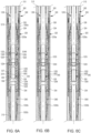
- FIG. 6A-6F An actuation sequence of the illustrated embodiment of the setting tool 1200 and liner hanger 300 is described in Figures 6A-6F .
- the setting tool 1200 and the liner hanger 300 are shown disposed in a casing 500.
- Figure 6A illustrates the setting tool 1200 and liner hanger 300 at a depth above the pressure chamber set depth.
- Figure 6B illustrates the setting tool 1200 and liner hanger 300 advanced to the pressure chamber set depth, such as a depth of 10,000ft (3,040m). Since the pressure chamber 1400 is in communication with the central bore 1202, the pressure chamber 1400 has a pressure equivalent to the pressure at the pressure chamber set depth. Pressure chamber set depth is determined, in part, on how much deeper the liner string 100 needs to be advanced in the wellbore.
- FIG. 6C illustrates the setting tool 1200 and liner hanger 300 at setting depth, such as a depth of 20,000ft (6,096m).
- first object 1410 engages the seat 1224
- pressure is increased above the first object 1410 to actuate the first sleeve 1220, and thus actuate the setting tool 1200.
- the pressure is increased above the first object 1410 until the one or more first shearable members 1250 shear and the first sleeve 1220 moves from the closed position to the open position as shown in Figure 6E .
- first sleeve 1220 is in the open position, fluid communication is reestablished between the pressure chamber 1400 and the central bore 1202 via the one or more first ports 1240. With the pressure chamber 1400 no longer isolated, it adjusts to the new pressure present at the setting depth.
- pressure may continue to be increased above the first object 1410 until the one or more shearable members 334 and the slip actuation assembly 330 moves the slips 324 up the ramps 326 into the set position.
- the one or more first shearable members 1250 may be designed to shear at the same pressure as the one or more shearable members 334.
- a test may be conducted to confirm that the liner hanger 300 has been set, such as by pulling or pushing on the liner string 100 from the surface to confirm that the slips 324 are set.
- the LHDA 110 may be released from the LHA 150, such as by rotating the LHDA 110 relative to the LHA 150 to unthread the threaded connection between threads 132 and 170. Releasing and verifying release of the LHDA 110 can be accomplished in the same manner discussed above with respect to setting tool 200. Then, pressure can be increased above the first object 1410 until the first object 1410 passes through the seat 1224 as shown in Figure 6F . The first object 1410 may continue to travel downhole and engage the plug assembly 140 or other wellbore equipment below the seat 1224. The first object 1410 may be removed from the seat 1224 prior to releasing the LHDA 110 from the LHA 150.
- a cementation operation may begin after the LHDA 110 is released from the LHA 150.
- the cementation operation may include dropping additional objects into the wellbore that engage the plug assembly 140.
- the packer 180 can be set in a similar manner as discussed above. In some embodiments, the packer 180 may be set without completing a cementation operation. Once the LHDA 110 has completed its operations, the LHDA 110 may be retrieved from the wellbore.
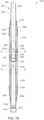
- Figure 7A-7C illustrates an alternative setting tool 2200 for the liner string 100.
- the LHDA 110 includes the setting tool 2200 instead of the setting tools 200 or 1200.
- Setting tool 2200 has similar components as setting tools 200, 1200 and the similar components are identified using similar reference signs.
- the setting tool 2200 may include a tubular housing 2210, a sleeve 2220, a first seal 2230a, a second seal 2230b, one or more threaded ports 2240t, one or more shearable plugs 2290, and a fluid bypass 2260.
- the tubular housing 2210 defines a central bore 2202.
- the tubular housing 2210 may include one or more sections 2210a-h connected together, such as by threaded couplings and/or fasteners. Seals 2211 may be placed between the interconnecting tubular housing sections to maintain sealing and pressure integrity of the setting tool 2200.
- the tubular housing 2210 has a connection each end, such as a pin 2201a a box 2201b.
- the one or more threaded ports 2240t are formed through the tubular housing 2210, such as through tubular housing section 2210d.
- the one or more threaded ports 2240t are disposed between the first and second seals 2230a,b.
- the first and second seals 2230a,b are configured to sealing engage with the inner surface of the bore 152 of the LHA 150 and to straddle the port 340.
- the seals 2230a,b may sealing engage with the inner surface of the tubular mandrel 310 of the liner hanger 300.
- a pressure chamber 2400 is present between the seals 2230a,b.
- the pressure chamber 2400 is filled with air at atmospheric pressure.
- the pressure chamber 2400 is filled with a fluid at a set pressure.
- the sleeve 2220 is movable from a closed position to an open position.
- the sleeve 2220 includes a seat 2224 and a retainer 2226.
- the seat 2224 may be coupled to or integrally formed with the sleeve 2220.
- the retainer 2226 may be a retaining recess or a retaining bore formed through a wall of the sleeve 2220 as shown in Figure 7A .
- One or more seals 2222 may be disposed about the seat 2224.
- the sleeve 2220 is disposed in the central bore 2202. When the sleeve 2220 is in the closed position, the sleeve 2220 is releasably attached to the tubular housing 2210 via one or more shearable plugs 2290.
- the shearable plugs 2290 are a shearable member. A cross section of the shearable plug 2290 is shown in Figure 9 .
- the shearable plugs 2290 may have threads 2292, a flow bore 2294, a closure member 2296, and a groove 2290.
- the threads 2292 correspond to the threads of the threaded port 2240t.
- the one or more shearable plugs 2290 are partially disposed in the one or more threaded ports 2240t and the retainer 2226 to hold the sleeve 2220 in the closed position.
- the closure member 2296 is at least partially disposed in the retainer 2226.
- the retainer 2226 may have threads corresponding to threads of the shearable plug 2290 located about the shearable member 2296.
- the closure member 436 is a cap.
- An O-ring 1299 may be placed in the groove 1298 to seal against the inner surface of the threaded port 2240t.
- a first object 2410 such as a ball or a dart, can be engaged with the seat 2224 to facilitate a pressure buildup above the first object 2410 in order to actuate the sleeve 2220.
- the one or more shearable plugs 2290 will fail along a shear plane in response to sufficient pressure such that a portion of the shearable plug 2290, such as the shearable member 2296, is sheared off by the sleeve 2220 to expose the flow bore 2294 as the sleeve 2220 moves from the closed positon to the open position. Once the flow bore 2294 is opened, a flow path is present between the central bore 2202 and the pressure chamber 2400.
- the retainer 2226 is configured to retain the sheared off portion of the shearable plug 2290, such as the closure member 2296, in order to prevent the sheared off portion from falling downhole.
- the fluid bypass 2260 is disposed in the tubular housing 2210 to allow communication above and below the first and second seals 2230a,b when the seals 2230a,b are sealingly engaged with inner surface of the bore 152 of the LHA 150.
- the fluid bypass 2260 allows for fluid communication around the seals 2230a,b.
- the fluid bypass 2260 allows the annulus portion 101a of the annulus 101 of the liner string 100 between by the packoff 112 and the first seal 2230a to be in fluid communication with the annulus portion 101b below the second seal 2230b.
- annulus portion 101a of the annulus between the packoff 112 and first seal 2230a can fill with wellbore fluid during run-in and pressure equalize to minimize the risk of collapse of a portion of the LHA 150 between the packoff 112 and the first seal 2230a.
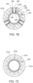
- Figures 7B-7C show cross sections of the setting tool 2200 to better illustrate the fluid bypass 2260 and setting tool 2200.
- the fluid bypass extends from one or more openings 2262a to one or more openings 2262b.
- the fluid bypass 2260 is not in fluid communication with the one or more threaded ports 2240t.
- the fluid bypass 2260 can be formed from a combination of gaps and/or bores present in the tubular housing 2210.
- one or more gaps 2270a may be present between the tubular housing sections 2210a and 2110c and one or more gaps 2270b may be present between tubular housing sections 2210f and 2210h.
- one or more bores 2272a may be formed in the tubular housing section 2210d.
- one or more bores 2272b may be formed in the tubular housing section 2210e.
- the gaps 2270a,b, bores 2272a,b, and openings 2262a,b form the fluid bypass 2260.
- the number of bores 2272a is less than the number of bores 2272b, and vice versa.
- the fluid bypass 2260 may be a plurality of individual fluid bypasses formed in the tubular housing 2210.
- the one or more ports are not threaded ports 2240t, and the shearable plugs 2290 do not have threads 2292 and are instead fastened into one or more of the ports with one or more fasteners, such as bolts.
- the shearable plug 2290 is made of metal.
- the shearable plug 2290 may be brass.
- the shearable plug 2290 may be formed from a plastic.
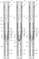
- FIGs 8A-8F An actuation sequence of the setting tool 2200 and liner hanger 300 is described in Figures 8A-8F .
- the setting tool 2200 and liner hanger 300 are shown disposed in the casing 500 at a setting depth.
- the sleeve 2220 is in the closed position.
- the pressure chamber 2400, and thus piston chamber 335, is isolated from the central bore 2202 by the one or more shearable plugs 2290 when the sleeve 2220 is in the closed position.
- the pressure chamber 2400 is isolated from the annulus portion 101a by the first seal 2230a.
- the pressure chamber 2400 is isolated from the annulus portion 101b by the second seal 2230b.
- a first object 2410 is dropped into the wellbore where it will engage with the seat 2224 as shown in Figure 8B .
- pressure is increased above the first object 2410 to actuate the sleeve 2220.
- the pressure is increased until the one or more shearable plugs 2290 shear and the sleeve 2220 moves from the closed position to the open position as shown in Figure 8C .
- the closure member 2296 is retained in the retainer 2226.
- fluid communication is established between the central bore 2202 and the slip actuation assembly 330 via the flow bore 2294 and port 340.
- the pressure chamber 2400 may continue to be increased above the first object 2410 until the one or more shearable members 334 shear and the slip actuation assembly 330 moves the slips 324 up the ramps 326 into the set position.
- the one or more shearable plugs 2290 may be designed to shear at the pressure necessary to shear the one or more shearable members 334.
- a test may be conducted to confirm that the liner hanger 300 has been set, such as by pulling or pushing on the liner string 100 from the surface to confirm that the slips 324 are set.
- the LHDA 110 is released from the LHA 150. Releasing and verifying release of the LHDA 110 can be accomplished in the same manner discussed above with respect to setting tool 200.
- pressure can be increased above the first object 2410 until the first object 2410 passes through the ball seat 2224, as shown in Figure 8D .
- the first object 2410 may be removed from the seat 2224 prior to releasing the LHDA 110 from the LHA 150.
- a cementation operation may begin once the LHDA 110 is released from the LHA 150.
- a second object 2420 such as a cementation dart or a ball, may be dropped into the liner string 100 above a cement.
- the second object 2420 travels in the liner string 100 until it engages the seat 2224, as shown in Figure 8E .
- Pressure may be increased above the second object 2420, if necessary, to pass the second object through the seat 2224.
- the second object 2420 will continue to travel through the LHDA 110 until it engages the plug assembly 140 or other wellbore equipment below the seat 2224.
- Figure 8F illustrates the setting tool 2200 disposed in the liner hanger 300 after the second object 2420 has passed through the seat 2224. Additional objects may be dropped as necessary to complete the cementation operation.
- the packer 180 may be set. In some embodiments, the packer 180 may be set without completing a cementation operation. Once the LHDA 110 has completed its wellbore operations, it may be retrieved from the wellbore.
- the setting tool 2200 includes a second set of one or more ports that are selectively blocked by a second sleeve in a similar manner as the setting tool 1200.
- the liner string 100 can be deployed into the wellbore with the pressure chamber 2400 in fluid communication with the central bore 2202.
- the second sleeve is actuated to isolate the pressure chamber 2400 from the central bore 2202.
- the liner string 100 can be deployed further into the wellbore until the setting depth is reached.
- the sleeve 2220 can be actuated to allow fluid communication between the pressure chamber 2400 and the central bore 2202.
- liner hanger 300 has been described, it is foreseeable that the setting tools 200, 1200, 2200 may be used to set downhole tools other than a liner hanger.
- the setting tools 220, 1200, 2200 may be used to set a packer, and the first and second seals are straddle a port of the packer.
- the one or more shearable members 250, 1250, 1254 are shear screws.
- An exemplary downhole operation of the liner string 100 begins by running the liner string 100 into the wellbore. Once the liner string reaches the setting depth, the respective setting tool 200, 1200, 2200 is actuated by increasing pressure above a first object 410, 1410, 2410 to allow the actuation of the liner hanger 300. Fluid pressure is increased above the first object engaged with the respective setting tool 200, 1200, 2200 until the slips 324 are set. Then a test may be conducted to confirm that the slips 324 are set. Then, the LHDA 110 may be released from the LHA 150. A test may be conducted to verify that the LHDA 110 has been released from the LHA 150. Then a cementation operation may occur.
- the packer 180 may be actuated.
- the packer 180 may be actuated by applying force (e.g., weight) to the top of the PBR 160 via dogs 122 after the LHDA 110 is lifted to allow the dogs 122 to move to the expanded position.
- force e.g., weight
- the liner string 100 lands on the bottom of the wellbore. If this occurs, the liner hanger 300 might not be actuated to set the slips 324.
- the LHDA 110 may be released from the LHA 150 before beginning a cementation operation. Once the cementation operation is completed, the packer 180 may then be set.
- the cementation operation occurs before the LHDA 110 is released from the LHA 150.
- the slips 324 are set after the completion of the cementing operation.
- the liner string 100 includes a setting tool with a second sleeve, such as second sleeve 1252.
- the liner string 100 is first advanced to a depth sufficient to actuate (e.g., trigger) the second sleeve to isolate the downhole tool actuation assembly, such as the slip actuation assembly 330.
- the plug assembly 140 includes one releasable plug which is actuated in response to an object dropped from the surface, such as the object used to actuate the setting tools 200, 1200, 2200.
- the plug assembly 140 includes more than one releasable plug, such as two releasable plugs or three releasable plugs.
- objects dropped from the surface actuate other wellbore equipment below the setting tools 200, 1200, 2200.
- the running tool 130 may not have threads 132 and the LHA 150 may not have threads 170. Instead, the running tool 130 may have collets and/or dogs that engage with a profile of the LHA 150. The running tool 130 is therefore releasably attached to the LHA 150 via the engagement of the collets and/or dogs with the profile. In some embodiments, the running tool may be similar to the running tool disclosed in US Patent No. 6,241,018 which is herein incorporated by reference.
- the packoff 112 is disposed above the running tool 130. In some embodiments, the packoff 112 is sealingly engaged with the inner surface of the PBR 160.
- the LHDA 110 may include two or more setting tools to set multiple downhole tools of the LHA 150.
- the object used to actuate the first setting tool may be used to set the other setting tools of the LHDA 110.
- a setting tool for a downhole tool includes a tubular housing having a central bore.
- the setting tool further includes a first seal and a second seal disposed about an exterior of the tubular housing.
- the setting tool further includes a first port formed through the tubular housing and disposed between the first seal and the second seal.
- the setting tool further includes a first sleeve disposed in the central bore and movable from a closed position to an open position, the first sleeve having a seat.
- the setting tool further includes at least one first shearable member configured to releasably attach the first sleeve to the tubular housing in the closed position.
- the setting tool further includes a fluid bypass disposed in the tubular housing and configured to allow fluid communication around the first seal and the second seal. The central bore and the first port are in fluid communication when the first sleeve is in the open position.
- fluid communication around the first and second seals comprises fluid communication between a first and a second opening disposed proximate opposite ends of the tubular housing, wherein the first and second seals are disposed between the first and the second openings.
- the tubular housing is composed of a plurality of tubular housing sections, and wherein the fluid bypass includes one or both of: one or more gaps between the tubular housing sections, and one or more bores through individual tubular housing sections.
- the fluid bypass is a first fluid bypass and the setting tool further includes a second fluid bypass disposed in the tubular housing and configured to allow fluid communication around the first seal and the second seal.
- the first sleeve blocks fluid communication between the central bore and the one or more first ports in the closed position.
- the setting tool includes a second port formed through the tubular housing and disposed between the first and second seals.
- the setting tool includes a second sleeve disposed in the central bore and movable from an open position to a closed position.
- the setting tool includes a chamber between the second sleeve and the tubular housing. The second port and the central bore are in fluid communication when the second sleeve is in the open position, and wherein fluid communication between the second port and the central bore is blocked when the second sleeve is in the closed position.
- the setting tool includes at least one second shearable member configured to releasably attach the second sleeve to the tubular housing in the open position.
- the at least one second shearable member and the chamber are configured such that the at least one second shearable member shears at a predetermined depth, and wherein the second sleeve moves to the closed position in response to a fluid pressure in the central bore.
- the second sleeve includes one or more sleeve ports in fluid communication with the central bore and the one or more second ports when the second sleeve is in the open position.
- the at least one first shearable member is at least one shearable plug, the shearable plug including a flow bore and a closure member, wherein the closure member blocks fluid communication between the central bore and the flow bore when the first sleeve is in the closed position.
- the closure member is configured to shear from the shearable plug to expose the flow bore to fluid communication with the central bore as the first sleeve moves to the open position.
- the first sleeve includes a retainer configured to retain the closure member that is sheared from the shearable plug.
- a liner string includes a liner hanger assembly and a liner hanger deployment assembly.
- the liner hanger assembly includes a liner hanger.
- the liner hanger includes a plurality of slips and a liner hanger actuation assembly configured to set the plurality of slips.
- the liner hanger deployment assembly is disposed within the liner hanger assembly.
- the liner hanger deployment assembly includes a setting tool configured to selectively allow fluid communication between a central bore of the setting tool and the liner hanger actuation assembly.
- the setting tool further includes a first sleeve disposed in the central bore and movable from a closed position to an open position.
- the liner string further includes a chamber in fluid communication with the liner hanger actuation assembly disposed between the setting tool and the liner hanger, wherein the chamber is isolated from the central bore when the first sleeve is in the closed position, and wherein the chamber is in fluid communication with the central bore when the first sleeve is in the open position.
- the first sleeve is maintained in the closed position by one or more shearable plugs including a closed flow bore, wherein a portion of the one or more shearable plugs is sheared to open the flow bore by the movement of the first sleeve from the closed to the open position, wherein the chamber is in fluid communication with the central bore via the opened flow bore.
- the setting tool further includes a first sleeve disposed in the central bore and movable from a closed position to an open position, and a second sleeve disposed in the central bore and movable from an open position to a closed position.
- the liner string further includes a chamber in fluid communication with the liner hanger actuation assembly disposed between the setting tool and the liner hanger, wherein the chamber is isolated from the central bore when the first sleeve is in the closed position and the second sleeve is in the closed position, wherein the chamber is in fluid communication with the central bore when the first sleeve is in the closed position and the second sleeve is in the open position, and wherein the chamber is in fluid communication with the central bore when the first sleeve is in the open position and the second sleeve is in the closed position.
- a method of actuating a liner hanger includes deploying a liner string including a liner hanger to a setting depth, wherein the liner string includes a setting tool disposed in the liner hanger, wherein the liner hanger includes an actuation assembly and a plurality of slips, and wherein the actuation assembly is isolated from fluid communication with a central bore of the setting tool at the setting depth.
- the method further includes opening a first fluid communication path between the central bore and the actuation assembly to establish fluid communication therebetween.
- the method further includes increasing the pressure in the central bore to actuate the actuation assembly to set the plurality of slips.
- the method of actuating a liner hanger includes prior to reaching the setting depth, deploying the liner string to a first depth. Upon reaching the first depth, a second fluid communication path between the central bore and the actuation assembly is closed to isolate the actuation assembly from fluid communication with the central bore.
- the method of actuating a liner hanger further includes retrieving the setting tool after setting the slips.
- a setting tool for a downhole tool includes a tubular housing having a central bore.
- the setting tool further includes a first seal and a second seal disposed about an exterior of the tubular housing.
- the setting tool further includes a first port formed through the tubular housing and disposed between the first seal and the second seal.
- the setting tool further a first sleeve disposed in the central bore and movable from a closed position to an open position, the first sleeve having a seat.
- the setting tool further includes a shearable plug disposed in the first port and configured to releasably attach the first sleeve to the tubular housing in the closed position.
- the shearable plug further includes a flow bore.
- the shearable plug further includes a closure member blocking fluid communication between the flow bore and the central bore, wherein the closure member is configured to be sheared away to expose the flow bore to fluid communication with the central bore, wherein the closure member is sheared away by the movement of the first sleeve from the closed position to the open position.
- the first sleeve includes a retainer configured to retain the closure member that is sheared from the shearable plug.
- the setting tool further includes one or more second ports formed through the tubular housing and disposed between the first and second seals.
- the setting tool further includes a second sleeve disposed in the central bore and movable from an open position to a closed position.
- the setting tool further includes a chamber between the second sleeve and the tubular housing.
- the setting tool further includes at least one second shearable member configured to releasably attach the second sleeve to the tubular housing in the closed position.
- the one or more second ports and the central bore are in fluid communication when the second sleeve is in the open position, and wherein fluid communication between the one or more second ports and the central bore is closed when the second sleeve is in the closed position.
- the at least one second shearable member and the chamber are configured such that the at least one second shearable member shears at a predetermined depth, and wherein the second sleeve moves to the closed position in response to a fluid pressure in the central bore.
- the second sleeve includes one or more sleeve ports in fluid communication with the central bore and the one or more second ports when the second sleeve is in the open position.
- a method of conducting a wellbore operation includes deploying a liner string into a wellbore to a setting depth.
- the liner string includes a liner hanger assembly including a liner hanger with an actuation assembly, and a liner hanger deployment assembly attached to the liner hanger assembly and including a setting tool, wherein the setting tool is configured to isolate the actuation assembly from fluid communication with a central bore of the setting tool.
- the method further includes actuating the setting tool to allow fluid communication between the central bore and the actuation assembly.
- the method further includes actuating the liner hanger.
- the method of conducing the wellbore operation further includes releasing the liner hanger deployment assembly from the liner hanger assembly.
- the method of conducing the wellbore operation further includes conducting a cementation operation.
- the method of conducing the wellbore operation further includes setting a packer of the liner hanger assembly.
- the setting tool includes a first sleeve and a second sleeve, wherein the second sleeve is configured to actuate at a first depth to isolate the actuation assembly from the central bore, and wherein the method further includes deploying the liner string to the first depth and actuating the second sleeve prior to deploying the liner string to the setting depth.
- a method of hanging a liner in a wellbore includes deploying a liner string to a setting depth in the wellbore.
- the liner sting includes a liner hanger having an actuation assembly, wherein the liner hanger is coupled to the liner.
- the liner string further includes a setting tool disposed in the liner hanger.
- the setting tool includes a central bore.
- the setting tool further includes a first sleeve having a seat, wherein the first sleeve is movable from a closed position to an open position, and wherein fluid communication between the central bore and the actuation assembly is blocked when the first sleeve is in the closed position and unblocked when the first sleeve is in the open position.
- the setting tool further includes one or more first shearable members configured to retain the first sleeve in the closed position.
- the method further includes moving the first sleeve from the closed position to the open position by engaging a first object with the seat to shear the one or more first shearable members.
- the method further includes actuating the actuation assembly to hang the liner.
- a method of hanging the liner in the wellbore prior to reaching the setting depth, deploying the liner hanger to a first depth, wherein a second sleeve of the setting tool moves from an open positon to a closed position in response to reaching the first depth to isolate the actuation assembly from the central bore.
Landscapes
- Life Sciences & Earth Sciences (AREA)
- Engineering & Computer Science (AREA)
- Geology (AREA)
- Mining & Mineral Resources (AREA)
- Physics & Mathematics (AREA)
- Environmental & Geological Engineering (AREA)
- Fluid Mechanics (AREA)
- General Life Sciences & Earth Sciences (AREA)
- Geochemistry & Mineralogy (AREA)
- Earth Drilling (AREA)
- Load-Engaging Elements For Cranes (AREA)
- Workshop Equipment, Work Benches, Supports, Or Storage Means (AREA)
Abstract
Description
- Embodiments of the present disclosure generally relate to a setting tool for actuating a liner hanger.
- Liner hangers are used to suspend a liner from another tubular string in a wellbore. Conventional hydraulic liner hangers are actuated in response to pressure above a threshold to set slips. During run-in, an increase in fluid circulation through the liner string may be necessary to facilitate moving the liner string through the deviations and/or turns of the wellbore. The increase in fluid circulation in the liner string may inadvertently actuate the liner hanger in the wellbore above the intended setting location. Unintended setting of the liner hanger results in the need to remove the liner string and to conduct a subsequent wellbore operation.
- There exists a need for a liner hanger setting tool that prevents premature actuation of the liner hanger.
- The present disclosure generally to a setting tool for a liner hanger and a methods for completing downhole operations.
- A setting tool for a downhole tool includes a tubular housing having a central bore. The setting tool further includes a first seal and a second seal disposed about an exterior of the tubular housing. The setting tool further includes a first port formed through the tubular housing and disposed between the first seal and the second seal. The setting tool further includes a first sleeve disposed in the central bore and movable from a closed position to an open position, the first sleeve having a seat. The setting tool further includes at least one first shearable member configured to releasably attach the first sleeve to the tubular housing in the closed position. The setting tool further includes a fluid bypass disposed in the tubular housing and configured to allow fluid communication around the first seal and the second seal. The central bore and the first port are in fluid communication when the first sleeve is in the open position.
- A liner string includes a liner hanger assembly and a liner hanger deployment assembly. The liner hanger assembly includes a liner hanger. The liner hanger includes a plurality of slips and a liner hanger actuation assembly configured to set the plurality of slips. The liner hanger deployment assembly is disposed within the liner hanger assembly. The liner hanger deployment assembly includes a setting tool configured to selectively allow fluid communication between a central bore of the setting tool and the liner hanger actuation assembly.
- A method of conducting a wellbore operation includes deploying a liner string into a wellbore to a setting depth. The liner string includes a liner hanger assembly including a liner hanger with an actuation assembly, and a liner hanger deployment assembly attached to the liner hanger assembly and including a setting tool, wherein the setting tool is configured to isolate the actuation assembly from fluid communication with a central bore of the setting tool. The method further includes actuating the setting tool to allow fluid communication between the central bore and the actuation assembly. The method further includes actuating the liner hanger.
- So that the manner in which the above recited features of the present disclosure can be understood in detail, a more particular description of the disclosure, briefly summarized above, may be had by reference to embodiments, some of which are illustrated in the appended drawings. It is to be noted, however, that the appended drawings illustrate only exemplary embodiments and are therefore not to be considered limiting of its scope, may admit to other equally effective embodiments.
-
Figures 1A-1C illustrate a liner string according to one embodiment.Figure 1A is a cross-sectional view of a liner hanger deployment assembly.Figure 1B is a cross-sectional view of the liner hanger assembly.Figure 1C is a cross-sectional view of the liner hanger deployment assembly within the liner hanger assembly. -
Figures 2A-2E illustrate an embodiment of a setting tool.Figure 2A is a cross-sectional view of the setting tool.Figure 2B is a cross-sectional view ofFigure 2A alongline 2B-2B.Figure 2C is a cross-sectional view ofFigure 2A along line 2C-2C.Figure 2D is a cross-sectional view ofFigure 2A alongline 2D-2D.Figure 2E is a cross-sectional view ofFigure 2A along line 2E-2E. -
Figure 3 is a cross-sectional view of a liner hanger according to one embodiment. -
Figures 4A-4F are cross-sectional views of the liner string disposed in the wellbore to illustrate an exemplary operation sequence of the liner string.Figure 4A illustrates the liner string at a setting depth, with the setting tool disposed in the liner hanger.Figure 4B illustrates a first object engaged with a seat of the setting tool.Figure 4C illustrates the actuated setting tool and actuated liner hanger.Figure 4D illustrates the first object no longer engaged with the seat.Figure 4E illustrates a second object engaged with the seat during a cementation operation.Figure 4F illustrates the second object no longer engaged with the seat. -
Figures 5A-5C illustrate an alternative embodiment of the setting tool.Figure 5A is a cross-sectional view of the setting tool.Figure 5B is a cross-sectional view ofFigure 5A along line 5B-5B.Figure 5C is a cross-sectional view ofFigure 5A along line 5C-5C. -
Figures 6A-F are cross-sectional views of the liner string disposed in the wellbore to illustrate an exemplary operation sequence of the liner string.Figure 6A illustrates the liner string at a depth above a pressure chamber set depth, with the setting tool disposed in the liner hanger.Figure 6B illustrates the liner string at the pressure chamber set depth.Figure 6C illustrates the liner string at the setting depth.Figure 6D illustrates a first object engaged with a seat of the setting tool.Figure 6E illustrates the actuated setting tool and actuated liner hanger.Figure 6F illustrates the first object no longer being engaged with the seat. -
Figures 7A-7C illustrate another embodiment of the setting tool.Figure 7A cross-sectional view of the setting tool.Figure 7B is a cross-sectional view ofFigure 7A along line 7B-7B.Figure 7C is a cross-sectional view ofFigure 7A alongline 7C-7C. -
Figures 8A-8F are cross-sectional views of an alternative liner string disposed in the wellbore to illustrate an exemplary operation sequence of the liner string.Figure 8A illustrates the liner string at a setting depth, with the setting tool disposed in the liner hanger.Figure 8B illustrates a first object engaged with a seat of the setting tool.Figure 8C illustrates the actuated setting tool and actuated liner hanger.Figure 8D illustrates the first object no longer being engaged with the seat.Figure 8E illustrates a second object engaged with the seat during a cementation operation.Figure 8F illustrates the second object no longer being engaged with the seat. -
Figure 9 illustrates a cross-section of a shearable plug according to one embodiment. - To facilitate understanding, identical reference numerals have been used, where possible, to designate identical elements that are common to the figures. It is contemplated that elements and features of one embodiment may be beneficially incorporated in other embodiments without further recitation.
-
Figures 1A-1C illustrate aliner string 100. Theliner string 100 includes a liner hanger deployment assembly (LHDA) 110, as shown inFigure 1A , and a liner hanger assembly (LHA) 150, as shown inFigure 1B . TheLHDA 110 may include apackoff 112, apacker actuator 120, a runningtool 130, asetting tool 200, and aplug assembly 140. TheLHA 150 may include a polished bore receptacle (PBR) 160,threads 170, apacker 180, aliner hanger 300, and aliner 190. TheLHA 150 may also include a landing collar (not shown), a float collar (not shown), and float shoe (not shown) at a lower end.Figure 1C illustrates theLHDA 110 disposed within theLHA 150. Anannulus 101 is between theLHDA 110 and theLHA 150. - During run-in of the
liner string 100, theLHDA 110 is disposed in thebore 152 and releasably attached to theLHA 150. As shown inFigure 1C , theLHDA 110 is attached to theLHA 150 via the engagement of threads 132 of the runningtool 130 with thethreads 170 during run-in. TheLHDA 110 may be released from theLHA 150 downhole, such as by unthreading the threaded connection betweenthreads 132 and 170. Thesetting tool 200 is disposed in theliner hanger 300 during run-in of theliner string 100. Circulation through theliner string 100 may be increased during run-in to facilitate moving theliner string 100 through deviations or turns in the wellbore. Thesetting tool 200 prevents premature actuation of theliner hanger 300 during run-in of theliner string 100. Once run-in of theliner string 100 is complete, thesetting tool 200 is actuated to allow the actuation of theliner hanger 300 in response to fluid pressure. In some embodiments, thesetting tool 200 can be actuated prior to the completion of run-in once theliner string 100 is close to the setting depth. After actuation of thesetting tool 200, theliner hanger 300 is actuated in response to reaching a pressure threshold. - The
packer 180 may include a tubular mandrel 181, apacking element 182, one or moreshearable members 183, and anactuation sleeve assembly 184. Theactuation sleeve assembly 183 is maintained in an initial position by the one or moreshearable members 183. ThePBR 160 abuts one end of thesleeve actuation assembly 184. Theactuation sleeve assembly 184 is configured to compress the packing element in response to force applied to thePBR 160 from thepacker actuator 120. - The
packer actuator 120 may be similar to the packer actuator disclosed inUS Pat. No. 9,322,235 packer actuator 120 includes a plurality ofdogs 122 movable from a retracted position to an extended position. Thedogs 122 are maintained in the retracted position by engagement with the inner surface of thePBR 160. In some embodiments, after theliner hanger 300 is set and theLHDA 110 is released from theLHA 150, theLHDA 110 can be lifted until thedogs 122 are withdrawn from thePBR 160 to allow thedogs 122 to move to the expanded position. TheLHDA 110 may then be lowered relative to theLHA 150 until thedogs 122 seat on the top of thePBR 160. Force (e.g., weight) is then applied to the top of thePBR 160 via thedogs 122, which transfers the force to thesleeve actuation assembly 184. Once the one or moreshearable members 183 shear, theactuation sleeve assembly 184 moves relative to the tubular mandrel 181 to compress thepacking element 182 until it expands into engagement with the wellbore or casing surrounding thepacker 180. Thus, thepacker actuator 120 is used to actuate the mechanically actuatedpacker 180 to seal the annulus surrounding theLHA 150 by expanding thepacking element 182 of thepacker 180. Upon completing operations downhole, theLHDA 110 is tripped out of the wellbore. TheLHA 150, however, remains in the wellbore. -
Figure 2A illustrates an embodiment of asetting tool 200. Thesetting tool 200 may include atubular housing 210, asleeve 220, afirst seal 230a, asecond seal 230b, one ormore ports 240, one or moreshearable members 250, and afluid bypass 260. Thetubular housing 210 defines acentral bore 202. To facilitate manufacturing and assembly, thetubular housing 210 may include one ormore sections 210a-h connected together, such as by threaded couplings and/or fasteners.Seals 211 may be placed between the interconnecting tubular housing sections 21 0a-h to prevent fluid in thecentral bore 202 from leaking to the environment outside of thesetting tool 200, and vice versa. Theseals 211 maintain pressure integrity of thesetting tool 200. Thetubular housing 210 has a connection at each end, such as apin 201a and abox 201b. Thefirst seal 230a and thesecond seal 230b are disposed about the exterior of thetubular housing 210. Thefirst seal 230a and thesecond seal 230b are configured to sealingly engage with an inner surface of thebore 152 of theLHA 150 and to straddle aport 340 of theliner hanger 300. For example, the first andsecond seals 230a,b may sealing engage with the inner surface of atubular mandrel 310 of theliner hanger 300. - The
fluid bypass 260 is disposed in thetubular housing 210. The fluid bypass extends from one ormore openings 262a to one ormore openings 262b. Thefluid bypass 260 allows fluid communication above and below the first andsecond seals 230a,b when theseals 230a,b are sealingly engaged with the inner surface of thebore 152 of theLHA 150, such as the inner surface of the tubular mandrel 310 (seeFigure 4A ). Thus, thefluid bypass 260 allows for fluid communication around theseals 230a,b. Thefluid bypass 260 is not in fluid communication with the one ormore ports 240. -
Figures 2B-2E show cross sections of thesetting tool 200 to better illustrate thefluid bypass 260 andsetting tool 200. The one ormore openings 262a are formed in thetubular housing section 210b. Thefluid bypass 260 can be formed from a combination of gaps between tubular sections and/or bores present in the tubular sections forming thetubular housing 210. For example, one ormore gaps 270a may be present between thetubular housing sections more gaps 270b may be present betweentubular housing sections 210f and 21 0h. As shown inFigures 2A and2C , one ormore bores 272a may be formed in thetubular housing section 210d. As shown inFigures 2A and2D , one ormore bores 272b may be formed in thetubular housing section 210e. The dashed lines intubular housing section 210d, as shown inFigure 2A , illustrate the one ormore bores 272a. Thegaps 270a,b, thebores 272a,b, and theopenings 262a,b form thefluid bypass 260. Thus, fluid may flow betweenopenings 262a,b via thegaps 270a,b and bores 272a,b. In some embodiments, the number ofbores 272a is less than the number ofbores 272b, and vice versa. In some embodiments, thefluid bypass 260 may be a plurality of individual fluid bypasses formed in thetubular housing 210 that are isolated from one another. - The
packoff 112 seals against the inner surface of theLHA 150, such as the inner surface of thepacker 180. As a result, a portion 101a of theannulus 101 is bounded by thepackoff 112 and thefirst seal 230a. A portion 101b of theannulus 101 is below thesecond seal 230b. Thefluid bypass 260 allows the portion 101a of theannulus 101 betweenpackoff 112 andfirst seal 230a to be in fluid communication with the portion 101b of the annulus below thesecond seal 230b. This allows the annulus portion 101a to fill with wellbore fluid during run-in and to equalize pressure with the annulus portion 101b. Without thefluid bypass 260, the annulus portion 101a would be isolated from the wellbore fluids. If the annulus portion 101a was isolated from the wellbore fluids, then a pressure difference between the annulus portion 101a and the annulus surrounding the outside of theLHA 150 would increase with depth, thereby increasing the risk of a collapse of theLHA 150, such as the collapse of the portion of the LHA150 between thefirst seal 230a and thepackoff 112. The collapse risk is caused, in part, by the thickness and material of theLHA 150. A collapse may prevent theLHDA 110 from being tripped out of theLHA 150, which might require tripping both theLHDA 110 andLHA 150 from the wellbore. Thefluid bypass 260 alleviates the pressure difference and allows theliner string 100 to be run-in to greater depths. - Prior to the actuation of the
setting tool 200, fluid communication between thecentral bore 202 and the one ormore ports 240 is blocked by thesleeve 220. Some of theports 240 are threadedports 240t for receiving ashearable member 250 that releasably attaches thesleeve 220 to thetubular housing 210. The one ormore ports 240, including the threadedports 240t, are formed throughtubular housing 210, such as throughtubular housing section 210d. As shown inFigure 2A and2C , theshearable members 250 are disposed in the threadedports 240t. However, one or all of theshearable members 250 may be disposed at another location in thetubular housing 210 instead of being disposed in the threadedports 240t. Theports 240, including the threadedports 240t, are disposed between the first andsecond seals 230a,b. - The
sleeve 220 is disposed in thecentral bore 202. Thesleeve 220 is movable from a closed positon (Figure 2A ) to an open position (Figure 4C ). When in the closed position, thesleeve 220 is releasably attached to thetubular housing 210, such astubular housing section 210d, by the one or moreshearable members 250. In some embodiments, theshearable members 250 may be threaded into a corresponding hole in thesleeve 220. In some embodiments, theshearable members 250 may be partially disposed in a groove or recess of thesleeve 220. In the open position, theshearable members 250 have sheared, and thesleeve 220 has moved relative to thetubular housing 210 to expose the one ormore ports 240 to fluid communication with thecentral bore 202. Thesleeve 220 may include one ormore seals 222 disposed around thesleeve 220 to prevent fluid communication between thecentral bore 202 and the one ormore ports 240 while thesleeve 220 is in the closed position. Thesleeve 220 includes aseat 224 configured to catch afirst object 410, such as a ball or a dart. Theseat 224 may be coupled to thesleeve 220, such as coupled to one end of thesleeve 220, or theseat 224 may be integrally formed with thesleeve 220. Aseal 222 may be disposed around theseat 224. When thefirst object 410 is engaged with theseat 224, pressure can be increased in thecentral bore 202 above thefirst object 410 to actuate thesetting tool 200. The pressure is increased above thefirst object 410 until the one or moreshearable members 250 are sheared, which frees thesleeve 220 to move from the closed position to the open position. The axial travel of thesleeve 220 may be limited by the abutment of thesleeve 220 with ashoulder 212 of thetubular housing 210. -
Figure 3 illustrates anexemplary liner hanger 300. Theliner hanger 300 may include thetubular mandrel 310, aslip assembly 320, and aslip actuation assembly 330. Thetubular mandrel 310 defines acentral bore 302 of theliner hanger 300 and includes theport 340. Theliner hanger 300 can have more than oneport 340. Theslip assembly 320 may include afirst abutment member 322 and a plurality ofslips 324 configured to ride up one ormore ramps 326 coupled to thetubular mandrel 310. Theslip actuation assembly 330 may include apiston member 331, asecond abutment member 332, asleeve member 333, one or moreshearable members 334, and apiston chamber 335 disposed between afirst seal 336 and asecond seal 337. - The
sleeve member 333 is attached to thetubular mandrel 310, such as by a plurality of fasteners. Thepiston member 331 is attached to thesecond abutment member 332 at one end. Thesecond seal 337 is coupled to thepiston member 331. Thepiston member 331 is releasably attached to thesleeve member 333 via the one or moreshearable members 334. In some embodiments, the one or moreshearable members 250 may be configured to shear at a lower pressure than the pressure necessary to shear the one or moreshearable members 334. Thefirst seal 336 is disposed between thetubular mandrel 310 and thepiston member 331, and thefirst seal 336 is affixed to thetubular mandrel 310. Thepiston chamber 335 is in fluid communication with theport 340. - In order to set the
slips 324, pressure is increased in thepiston chamber 335 until the force acting on thepiston head 331h of thepiston member 331 is sufficient to shear the one or moreshearable members 334. Then, thepiston member 331,second seal 337, and thesecond abutment member 332 move, in response to the fluid inpiston chamber 335, relative to thetubular mandrel 310 until thesecond abutment member 332 engages thefirst abutment member 322. Once engaged, thefirst abutment member 322 moves in response to the continued movement of thesecond abutment member 332 andpiston member 331 until theslips 324 ride up theramps 326 into engagement with a casing or an inner surface of the wellbore. -
Figure 4A illustrates thesetting tool 200 disposed in thecentral bore 302 of theliner hanger 300. TheLHDA 110 is still attached to theLHA 150. Theseals 230a,b are shown as engaged with thetubular mandrel 310. Apressure chamber 400 is disposed between theseals 230a,b when theseals 230a,b are engaged with the inner surface of thebore 152 of theLHA 150. Theport 340 is disposed between theseals 230a,b such that it is in fluid communication with thepressure chamber 400. Thepressure chamber 400 is isolated from fluid communication with thecentral bore 202 via thesleeve 220. Thepressure chamber 400 is isolated from the annulus portions 101a by thefirst seal 230a. Thepressure chamber 400 is isolated from the annulus portion 101b by thesecond seal 230b. Thepressure chamber 400 may be at atmospheric pressure, or it may be pressurized to a set pressure. Thepressure chamber 400, and thus thepiston chamber 335, is isolated from fluid communication with thecentral bore 202 during run-in to avoid inadvertent actuation of theliner hanger 300. - An exemplary operation sequence of the
liner string 100 including thesetting tool 200 andliner hanger 300 is illustrated inFigures 4A-4F . Thesetting tool 200 and theliner hanger 300 are shown disposed in acasing 500. As shown inFigure 4A , thesetting tool 200 andliner hanger 300 are at the setting depth in the wellbore. Once theliner hanger 300 is in position at the setting depth, thesetting tool 200 is ready to be actuated. Thefirst object 410 is dropped into the wellbore where it will engage with theseat 224 as shown inFigure 4B . After thefirst object 410 engages theseat 224, pressure is increased above thefirst object 410 until the one or moreshearable members 250 shear and thesleeve 220 moves from the closed position to the open position as shown inFigure 4C . When thesleeve 220 is in the open position, fluid communication is established between the one ormore ports 240 and theport 340. With thepressure chamber 400 no longer isolated from thecentral bore 202, thepressure chamber 400 may fill with wellbore fluid. The operator may wait a certain period of time to allow thepressure chamber 400 to fill with wellbore fluids. As shown inFigure 4C , pressure may continue to be increased above thefirst object 410 until the one or moreshearable members 334 shear. As a result, theslip actuation assembly 330 moves theslips 324 up theramps 326 to the set position. However, the one or moreshearable members 250 may be designed to shear at the pressure necessary to shear the one or moreshearable members 334. A test may be conducted to confirm theliner hanger 300 has been set, such as by pulling or pushing on theliner string 100 from the surface to confirm that theslips 324 are set. Then, theLHDA 110 may be released from theLHA 150. In one example, theLHDA 110 is rotated relative to theLHA 150 to unthread the threaded connection between thread 132 andthread 170. Release of theLHDA 110 from theLHA 150 may be verified by lifting the LHDA 110 a predetermined distance and checking the weight on a load sensor to confirm that theLHA 150 is no longer attached. Pressure can be increased above thefirst object 410 until thefirst object 410 passes through theseat 224 as shown inFigure 4D . Thefirst object 410 will travel downhole, and thefirst object 410 may engage with or pass through theplug assembly 140 or other wellbore equipment below theseat 224. In some embodiments, theobject 140 is removed from theseat 224 prior to releasing theLHDA 110 from theLHA 150. - In some embodiments, once the
LHDA 110 is released from theLHA 150, a cementation operation may begin. For example, asecond object 420, such as a cementation dart or a ball, may be dropped into theliner string 100 above the cement. Thesecond object 420 travels downhole until it engages theseat 224 as shown inFigure 4E . Pressure may be increased above thesecond object 420, if necessary, to pass the second object through theseat 224. Thesecond object 420 may continue to travel through theLHDA 110, and thesecond object 420 may engage theplug assembly 140 or other wellbore equipment below theseat 224.Figure 4F illustrates thesetting tool 200 disposed in theliner hanger 300 after thesecond object 420 has passed through theseat 224. Additional objects may be dropped as necessary to complete the cementation operation. - Once the cementation operation is complete, the
LHDA 110 may be lifted until thedogs 122 are removed from thePBR 160, which results in thedogs 122 moving from the unexpanded position to the expanded position. Then, theLHDA 110 is lowered relative to theLHA 150 until thedogs 122 seat on the top of thePBR 160. Then, force (e.g., weight) can be applied to theLHDA 110 to set the mechanically actuatedpacker 180 via thedogs 122 seated on thePBR 160. After thepacker 180 is set, then theLHDA 110 may be tripped out of the wellbore. In some embodiments, thepacker 180 may be set without completing a cementation operation. -
Figure 5A-5C illustrates analternative setting tool 1200 for use with theliner string 100. Thesetting tool 1200 may be substituted for thesetting tool 200 in theLHDA 110. Thesetting tool 1200 has similar components as settingtool 200, and the similar components are identified using similar reference numbers. -
Figure 5A illustrates settingtool 1200. Thesetting tool 1200 may include atubular housing 1210, afirst sleeve 1220, asecond sleeve 1252, afirst seal 1230a, asecond seal 1230b, one or morefirst ports 1240, one or moresecond ports 1242, one or more firstshearable members 1250, one or more secondshearable members 1254, and afluid bypass 1260. Thetubular housing 1210 defines acentral bore 1202. To facilitate manufacturing and assembly, thetubular housing 1210 may include one ormore sections 1210a-h connected together, such as by threaded couplings and/or fasteners.Seals 1211 may be placed between the interconnectingtubular housing sections 1210a-h to maintain the sealing and pressure integrity of thesetting tool 1200. Thetubular housing 1210 has a connection each end, such as apin 1201a abox 1201b. Thefirst seal 1230a and thesecond seal 1230b are disposed about the exterior of thetubular housing 1210. The first andsecond seals 1230a,b are configured to sealing engage with the inner surface of thebore 152 of theLHA 150 and to straddle theport 340 of theliner hanger 300. For example, theseals 1230a,b are configured to sealingly engage against the inner surface of thetubular mandrel 310 of theliner hanger 300. While the first andsecond seals 1230a,b are engaged with the inner surface of thebore 152 of theLHA 150, apressure chamber 1400 is present between theseals 1230a,b. - The one or more
first ports 1240 are formed through thetubular housing 1210, such as throughtubular housing section 1210d. Some of thefirst ports 1240 are threadedports 1240t for receiving the one or more firstshearable members 1250 that releasably attach thefirst sleeve 1220 to thetubular housing 1210. As shown inFigure 5A and5B , the one or more firstshearable members 1250 are disposed in the threadedports 1240t. However, the one or more firstshearable members 1250 may be disposed at another location in thetubular housing 1210 instead of being disposed in the threadedports 1240t. The one or morefirst ports 1240, including the threadedports 1240t, are disposed between the first andsecond seals 1230a,b. - The
first sleeve 1220 is disposed in thecentral bore 1202. Thefirst sleeve 1220 is movable from a closed positon (Figure 5A ) to an open position (Figure 6C ). When in the closed position, thefirst sleeve 1220 is releasably attached to thetubular housing 1210, such astubular housing section 1210d, by the one or more firstshearable members 1250. Thefirst sleeve 1220 includes aseat 1224 configured to catch afirst object 1410, such as a ball or a dart. Theseat 1224 may be coupled to thefirst sleeve 1220. For example, theseat 1224 can be coupled to one end of thefirst sleeve 1220. In another example, theseat 1224 may be integrally formed with thefirst sleeve 1220. A plurality ofseals 1222 may be disposed around thefirst sleeve 1220 and theseat 224. When thefirst object 1410 is engaged with theseat 1224, pressure can be increased in thecentral bore 1202 above thefirst object 1410 to actuate thesetting tool 1200. The pressure is increased above thefirst object 1410 until the one or more firstshearable members 1250 are sheared. Thereafter, thefirst sleeve 1220 is allowed to move from the closed position to the open position. - The
second sleeve 1252 is disposed in thecentral bore 1202 and is releasably attached to thetubular housing 1210, such as being releasably attached totubular housing section 1210e, when in the open position. One ormore seals 1228 may be disposed about thesecond sleeve 1252, and theseals 1228 may straddle the one or moresecond ports 1242. When thesecond sleeve 1252 is in the open position (Figure 5A ), thecentral bore 1202 is in fluid communication with one or moresecond ports 1242 formed in thetubular housing 1210. In some embodiments, and as shown inFigure 5A , thesecond sleeve 1252 includes one ormore ports 1256 that are aligned with the one or moresecond ports 1242 when thesecond sleeve 1252 is in the open position. The one or moresecond ports 1242 may be formed in thetubular housing section 1210e and some of the one or moresecond ports 1242 may be threaded 1242t. The one or moresecond ports 1242, including the threadedports 1242t, are disposed between the first andsecond seals 1230a,b. As shown inFigure 5A and5C , thesecond sleeve 1252 is releasably attached to thetubular housing 1210 via one or more secondshearable members 1254. In some embodiments, and as shown inFigures 5A , thesecond sleeve 1252 is not pressure balanced. Achamber 1280 is disposed between thesecond sleeve 1252 and thetubular housing 1210. Thechamber 1280 is isolated from thecentral bore 1202 and the one or moresecond ports 1242 via theseals 1228. Thechamber 1280 may be at atmospheric pressure or the chamber may contain a fluid at a specific pressure, such as 500 psi (approximately 3.45 MPa) for example. As thesetting tool 1200 travels deeper into the wellbore, the pressure differential between thechamber 1280 and thecentral bore 1202 increases. The pressure in thepressure chamber 1400 increases with depth, since thepressure chamber 1400 is in fluid communication with thecentral bore 1202. The pressure in thechamber 1280 and the one or more secondshearable members 1254 are configured to actuate thesecond sleeve 1252 at a desired depth. For example, the number, thickness, and material of the one or more secondshearable members 1254 and/or the pressure in thechamber 1280 can be adjusted based on the desired depth at which thesecond sleeve 1252 moves to the closed position. Thus, when thesetting tool 1200 reaches the desired depth, the secondshearable members 1254 shear due to the pressure difference between the pressure acting on thesecond sleeve 1252 in thecentral bore 1202 and the pressure in thechamber 1280. The desired depth at which thesecond sleeve 1252 actuates to move to the closed position is the set depth of thepressure chamber 1400. When thesecond sleeve 1252 is in the closed position, thepressure chamber 1400 is isolated from thecentral bore 1202, preventing the pressure in thepressure chamber 1400 from continuing to increase. - In some embodiments, flow rate can be used to actuate the
second sleeve 1252. Fluid flow above a predetermined rate will be sufficient to increase the pressure in thecentral bore 1202 to act upon thesecond sleeve 1252 to shear the one or more secondshearable members 1254. After release, thesecond sleeve 1252 is allowed to move to a closed position to block flow from thecentral bore 1202 through the one or moresecond ports 1242. However, the flow rate necessary to shear the one or more secondshearable members 1254 and to move thesecond sleeve 1252 is insufficient to actuate theslip actuation assembly 330. In some embodiments, thesecond sleeve 1252 is actuated after catching an object in a seat of thesecond sleeve 1252. Thesecond sleeve 1252 is moved to the closed position by increasing pressure above the object engaged in the seat of thesecond sleeve 1252 until the one or more secondshearable members 1254 shear. In some embodiments, thesecond sleeve 1252 is pressure balanced and further includes a seat to catch an object. Thesecond sleeve 1252 can move from the open position to the closed position in response to a pressure build-up above the object that is sufficient to shear the one or more secondshearable members 1254. - The
fluid bypass 1260 is disposed in thetubular housing 1210 to allow communication above and below the first andsecond seals 1230a,b when theseals 1230a,b are sealingly engaged with the inner surface of thebore 152 of theLHA 150, such as the inner surface of thetubular mandrel 310. Thus, thefluid bypass 1260 allows for fluid communication around theseals 1230a,b. The fluid bypass extends from one ormore openings 1262a to one ormore openings 1262b. Thefluid bypass 1260 is not in fluid communication with the one or morefirst ports 1240 or the one or moresecond ports 1242. Thefluid bypass 1260 allows the annulus portion 101a of theliner string 100 between thepackoff 112 and thefirst seal 1230a to be in fluid communication with the annulus portion 101b below thesecond seal 1230b. Thus, annulus portion 101a of theannulus 101 between thepackoff 112 andfirst seal 1230a can fill with wellbore fluid during run-in to achieve pressure equalization to minimize the risk of collapse of a portion of theLHA 150 between thepackoff 112 and thefirst seal 1230a. -
Figures 5B-5C show cross sections of thesetting tool 1200 to better illustrate thefluid bypass 1260 andsetting tool 1200. Thefluid bypass 1260 can be formed from a combination of gaps and/or bores present in thetubular housing 1210. For example, one ormore gaps 1270a may be present between thetubular housing sections more gaps 1270b may be present betweentubular housing sections Figure 5A (dashed lines) andFigure 5B , one ormore bores 1272a may be formed in thetubular housing section 1210d. As shown inFigure 5A (dashed lines) andFigure 5C , one ormore bores 1272b may be formed in thetubular housing section 1210e. Thegaps 1270a,b, bores 1272a,b, andopenings 1262a,b form thefluid bypass 1260. In some embodiments, the number ofbores 1272a is less than the number ofbores 1272b, and vice versa. In some embodiments, thefluid bypass 1260 may be a plurality of individual fluid bypasses formed in thetubular housing 1210. -
Figure 6A illustrates thesetting tool 1200 disposed in theliner hanger 300 when theLHDA 110 is attached to theLHA 150. Thepressure chamber 1400 is isolated from the annulus portion 101a by thefirst seal 1230a. Thepressure chamber 1400 is isolated from the annulus portion 101b by thesecond seal 1230b. Thepressure chamber 1400 is in fluid communication with thecentral bore 1202 via the one or moresecond ports 1242 and the corresponding one ormore ports 1256 of thesecond sleeve 1252. Thus, any fluid initially in thepressure chamber 1400, such as air, may be at least partially displaced by wellbore fluids during run-in. At thepressure chamber 1400 set depth, which is a predetermined depth, thesecond sleeve 1252 is actuated and moves from the open position to the closed position. After thesecond sleeve 1252 is actuated, thepressure chamber 1400 is isolated from thecentral bore 1202 by thefirst sleeve 1220 and thesecond sleeve 1252. The now isolatedpressure chamber 1400 has a pressure that is equivalent to the fluid pressure at the depth where it was isolated from fluid communication with thecentral bore 1202 by thesecond sleeve 1252. After actuating thesecond sleeve 1252, theliner string 100 is advanced to a greater depth while thepressure chamber 1400 is isolated from fluid flow. Thepressure chamber 1400 is isolated from fluid flow by thefirst sleeve 1220 and thesecond sleeve 1252 to prevent inadvertent actuation of theslip actuation assembly 330. It is believed that a greater final setting depth can be achieved than if thepressure chamber 1400 remained at its initial run-in pressure. Once theliner string 100 is at setting depth, thefirst object 1410 can engage with thefirst sleeve 1220 to actuate of thefirst sleeve 1220. Pressure is increased above thefirst object 1410 to shear the one or more firstshearable members 1250, which allows thefirst sleeve 1220 to move to the open position. Once thefirst sleeve 1220 is in the open position, fluid pressure is increased until theslip actuation assembly 330 sets theslips 324. - An actuation sequence of the illustrated embodiment of the
setting tool 1200 andliner hanger 300 is described inFigures 6A-6F . Thesetting tool 1200 and theliner hanger 300 are shown disposed in acasing 500.Figure 6A illustrates thesetting tool 1200 andliner hanger 300 at a depth above the pressure chamber set depth.Figure 6B illustrates thesetting tool 1200 andliner hanger 300 advanced to the pressure chamber set depth, such as a depth of 10,000ft (3,040m). Since thepressure chamber 1400 is in communication with thecentral bore 1202, thepressure chamber 1400 has a pressure equivalent to the pressure at the pressure chamber set depth. Pressure chamber set depth is determined, in part, on how much deeper theliner string 100 needs to be advanced in the wellbore. After thepressure chamber 1400 set depth has been reached, thesecond sleeve 1252 moves to the closed position. Thepressure chamber 1400 is now isolated from thecentral bore 1202 of thesetting tool 1200. Theliner string 100 can now be advanced deeper in the wellbore, such as a depth of 20,000ft (6,096m), without a collapse event occurring.Figure 6C illustrates thesetting tool 1200 andliner hanger 300 at setting depth, such as a depth of 20,000ft (6,096m). Once theliner hanger 300 is at setting depth, thefirst object 1410 is dropped into the wellbore. Thefirst object 1410 engages theseat 1224 as shown inFigure 6D . After thefirst object 1410 engages theseat 1224, pressure is increased above thefirst object 1410 to actuate thefirst sleeve 1220, and thus actuate thesetting tool 1200. The pressure is increased above thefirst object 1410 until the one or more firstshearable members 1250 shear and thefirst sleeve 1220 moves from the closed position to the open position as shown inFigure 6E . When thefirst sleeve 1220 is in the open position, fluid communication is reestablished between thepressure chamber 1400 and thecentral bore 1202 via the one or morefirst ports 1240. With thepressure chamber 1400 no longer isolated, it adjusts to the new pressure present at the setting depth. As shown inFigure 6E , pressure may continue to be increased above thefirst object 1410 until the one or moreshearable members 334 and theslip actuation assembly 330 moves theslips 324 up theramps 326 into the set position. However, the one or more firstshearable members 1250 may be designed to shear at the same pressure as the one or moreshearable members 334. A test may be conducted to confirm that theliner hanger 300 has been set, such as by pulling or pushing on theliner string 100 from the surface to confirm that theslips 324 are set. Once the operator has determined that theliner hanger 300 is set, theLHDA 110 may be released from theLHA 150, such as by rotating theLHDA 110 relative to theLHA 150 to unthread the threaded connection betweenthreads 132 and 170. Releasing and verifying release of theLHDA 110 can be accomplished in the same manner discussed above with respect to settingtool 200. Then, pressure can be increased above thefirst object 1410 until thefirst object 1410 passes through theseat 1224 as shown inFigure 6F . Thefirst object 1410 may continue to travel downhole and engage theplug assembly 140 or other wellbore equipment below theseat 1224. Thefirst object 1410 may be removed from theseat 1224 prior to releasing theLHDA 110 from theLHA 150. - In some embodiments, a cementation operation may begin after the
LHDA 110 is released from theLHA 150. The cementation operation may include dropping additional objects into the wellbore that engage theplug assembly 140. Once the cementation operation is completed, then thepacker 180 can be set in a similar manner as discussed above. In some embodiments, thepacker 180 may be set without completing a cementation operation. Once theLHDA 110 has completed its operations, theLHDA 110 may be retrieved from the wellbore. -
Figure 7A-7C illustrates analternative setting tool 2200 for theliner string 100. TheLHDA 110 includes thesetting tool 2200 instead of thesetting tools Setting tool 2200 has similar components as settingtools - The
setting tool 2200 may include atubular housing 2210, asleeve 2220, afirst seal 2230a, asecond seal 2230b, one or more threadedports 2240t, one or moreshearable plugs 2290, and afluid bypass 2260. Thetubular housing 2210 defines acentral bore 2202. To facilitate manufacturing and assembly, thetubular housing 2210 may include one ormore sections 2210a-h connected together, such as by threaded couplings and/or fasteners. Seals 2211 may be placed between the interconnecting tubular housing sections to maintain sealing and pressure integrity of thesetting tool 2200. Thetubular housing 2210 has a connection each end, such as apin 2201a abox 2201b. The one or more threadedports 2240t are formed through thetubular housing 2210, such as throughtubular housing section 2210d. The one or more threadedports 2240t, are disposed between the first andsecond seals 2230a,b. The first andsecond seals 2230a,b are configured to sealing engage with the inner surface of thebore 152 of theLHA 150 and to straddle theport 340. For example, theseals 2230a,b may sealing engage with the inner surface of thetubular mandrel 310 of theliner hanger 300. While the first andsecond seals 2230a,b are engaged with the inner surface of thebore 152, apressure chamber 2400 is present between theseals 2230a,b. In some embodiments, thepressure chamber 2400 is filled with air at atmospheric pressure. In some embodiments, thepressure chamber 2400 is filled with a fluid at a set pressure. - The
sleeve 2220 is movable from a closed position to an open position. Thesleeve 2220 includes aseat 2224 and aretainer 2226. Theseat 2224 may be coupled to or integrally formed with thesleeve 2220. Theretainer 2226 may be a retaining recess or a retaining bore formed through a wall of thesleeve 2220 as shown inFigure 7A . One ormore seals 2222 may be disposed about theseat 2224. Thesleeve 2220 is disposed in thecentral bore 2202. When thesleeve 2220 is in the closed position, thesleeve 2220 is releasably attached to thetubular housing 2210 via one or more shearable plugs 2290. The shearable plugs 2290 are a shearable member. A cross section of theshearable plug 2290 is shown inFigure 9 . The shearable plugs 2290 may havethreads 2292, aflow bore 2294, aclosure member 2296, and agroove 2290. Thethreads 2292 correspond to the threads of the threadedport 2240t. The one or moreshearable plugs 2290 are partially disposed in the one or more threadedports 2240t and theretainer 2226 to hold thesleeve 2220 in the closed position. Theclosure member 2296 is at least partially disposed in theretainer 2226. Theretainer 2226 may have threads corresponding to threads of theshearable plug 2290 located about theshearable member 2296. As shown inFigure 9 , the closure member 436 is a cap. An O-ring 1299 may be placed in the groove 1298 to seal against the inner surface of the threadedport 2240t. - Before the
sleeve 2220 is actuated to move from the closed position to the open position, fluid communication between thecentral bore 2202 and thepressure chamber 2400 is blocked by theshearable plug 2290. Afirst object 2410, such as a ball or a dart, can be engaged with theseat 2224 to facilitate a pressure buildup above thefirst object 2410 in order to actuate thesleeve 2220. The one or moreshearable plugs 2290 will fail along a shear plane in response to sufficient pressure such that a portion of theshearable plug 2290, such as theshearable member 2296, is sheared off by thesleeve 2220 to expose the flow bore 2294 as thesleeve 2220 moves from the closed positon to the open position. Once the flow bore 2294 is opened, a flow path is present between thecentral bore 2202 and thepressure chamber 2400. In some embodiments theretainer 2226 is configured to retain the sheared off portion of theshearable plug 2290, such as theclosure member 2296, in order to prevent the sheared off portion from falling downhole. - The
fluid bypass 2260 is disposed in thetubular housing 2210 to allow communication above and below the first andsecond seals 2230a,b when theseals 2230a,b are sealingly engaged with inner surface of thebore 152 of theLHA 150. Thus, thefluid bypass 2260 allows for fluid communication around theseals 2230a,b. Thefluid bypass 2260 allows the annulus portion 101a of theannulus 101 of theliner string 100 between by thepackoff 112 and thefirst seal 2230a to be in fluid communication with the annulus portion 101b below thesecond seal 2230b. Thus, the annulus portion 101a of the annulus between thepackoff 112 andfirst seal 2230a can fill with wellbore fluid during run-in and pressure equalize to minimize the risk of collapse of a portion of theLHA 150 between thepackoff 112 and thefirst seal 2230a. -
Figures 7B-7C show cross sections of thesetting tool 2200 to better illustrate thefluid bypass 2260 andsetting tool 2200. The fluid bypass extends from one ormore openings 2262a to one ormore openings 2262b. Thefluid bypass 2260 is not in fluid communication with the one or more threadedports 2240t. Thefluid bypass 2260 can be formed from a combination of gaps and/or bores present in thetubular housing 2210. For example, one ormore gaps 2270a may be present between thetubular housing sections 2210a and 2110c and one or more gaps 2270b may be present betweentubular housing sections Figure 7A (dashed lines) andFigure 7B , one ormore bores 2272a may be formed in thetubular housing section 2210d. As shown inFigures 7A (dashed lines) andFigure 7C , one ormore bores 2272b may be formed in thetubular housing section 2210e. Thegaps 2270a,b, bores 2272a,b, andopenings 2262a,b form thefluid bypass 2260. In some embodiments, the number ofbores 2272a is less than the number ofbores 2272b, and vice versa. In some embodiments, thefluid bypass 2260 may be a plurality of individual fluid bypasses formed in thetubular housing 2210. - In some embodiments, the one or more ports are not threaded
ports 2240t, and theshearable plugs 2290 do not havethreads 2292 and are instead fastened into one or more of the ports with one or more fasteners, such as bolts. In some embodiments, theshearable plug 2290 is made of metal. For example, theshearable plug 2290 may be brass. In some embodiments, theshearable plug 2290 may be formed from a plastic. - An actuation sequence of the
setting tool 2200 andliner hanger 300 is described inFigures 8A-8F . Thesetting tool 2200 andliner hanger 300 are shown disposed in thecasing 500 at a setting depth. As shown inFigure 8A , thesleeve 2220 is in the closed position. Thepressure chamber 2400, and thuspiston chamber 335, is isolated from thecentral bore 2202 by the one or moreshearable plugs 2290 when thesleeve 2220 is in the closed position. Thepressure chamber 2400 is isolated from the annulus portion 101a by thefirst seal 2230a. Thepressure chamber 2400 is isolated from the annulus portion 101b by thesecond seal 2230b. After theliner hanger 300 reaches setting depth, afirst object 2410 is dropped into the wellbore where it will engage with theseat 2224 as shown inFigure 8B . After thefirst object 2410 engages theseat 2224, pressure is increased above thefirst object 2410 to actuate thesleeve 2220. The pressure is increased until the one or moreshearable plugs 2290 shear and thesleeve 2220 moves from the closed position to the open position as shown inFigure 8C . As shown, theclosure member 2296 is retained in theretainer 2226. When thesleeve 2220 is in the open position, thepressure chamber 2400, and thuspiston chamber 335, is no longer isolated from thecentral bore 2202. Thus fluid communication is established between thecentral bore 2202 and theslip actuation assembly 330 via theflow bore 2294 andport 340. For example, if thepressure chamber 2400 was originally filed with air, it fills with wellbore fluids once the flow bore 2294 is exposed. As shown inFigure 8C , pressure may continue to be increased above thefirst object 2410 until the one or moreshearable members 334 shear and theslip actuation assembly 330 moves theslips 324 up theramps 326 into the set position. In some embodiments, however, the one or moreshearable plugs 2290 may be designed to shear at the pressure necessary to shear the one or moreshearable members 334. - A test may be conducted to confirm that the
liner hanger 300 has been set, such as by pulling or pushing on theliner string 100 from the surface to confirm that theslips 324 are set. Once the operator has determined that theliner hanger 300 is set, theLHDA 110 is released from theLHA 150. Releasing and verifying release of theLHDA 110 can be accomplished in the same manner discussed above with respect to settingtool 200. Then pressure can be increased above thefirst object 2410 until thefirst object 2410 passes through theball seat 2224, as shown inFigure 8D . In some embodiments, thefirst object 2410 may be removed from theseat 2224 prior to releasing theLHDA 110 from theLHA 150. - In some embodiments, a cementation operation may begin once the
LHDA 110 is released from theLHA 150. For example, asecond object 2420, such as a cementation dart or a ball, may be dropped into theliner string 100 above a cement. Thesecond object 2420 travels in theliner string 100 until it engages theseat 2224, as shown inFigure 8E . Pressure may be increased above thesecond object 2420, if necessary, to pass the second object through theseat 2224. Thesecond object 2420 will continue to travel through theLHDA 110 until it engages theplug assembly 140 or other wellbore equipment below theseat 2224.Figure 8F illustrates thesetting tool 2200 disposed in theliner hanger 300 after thesecond object 2420 has passed through theseat 2224. Additional objects may be dropped as necessary to complete the cementation operation. - After the cementation operation is complete, the
packer 180 may be set. In some embodiments, thepacker 180 may be set without completing a cementation operation. Once theLHDA 110 has completed its wellbore operations, it may be retrieved from the wellbore. - In some embodiments, the
setting tool 2200 includes a second set of one or more ports that are selectively blocked by a second sleeve in a similar manner as thesetting tool 1200. Thus, theliner string 100 can be deployed into the wellbore with thepressure chamber 2400 in fluid communication with thecentral bore 2202. When apressure chamber 2400 set depth is reached, the second sleeve is actuated to isolate thepressure chamber 2400 from thecentral bore 2202. Theliner string 100 can be deployed further into the wellbore until the setting depth is reached. At the setting depth, thesleeve 2220 can be actuated to allow fluid communication between thepressure chamber 2400 and thecentral bore 2202. - While
liner hanger 300 has been described, it is foreseeable that thesetting tools setting tools - In some embodiments, the one or more
shearable members - An exemplary downhole operation of the
liner string 100 begins by running theliner string 100 into the wellbore. Once the liner string reaches the setting depth, therespective setting tool first object liner hanger 300. Fluid pressure is increased above the first object engaged with therespective setting tool slips 324 are set. Then a test may be conducted to confirm that theslips 324 are set. Then, theLHDA 110 may be released from theLHA 150. A test may be conducted to verify that theLHDA 110 has been released from theLHA 150. Then a cementation operation may occur. Once the cementation operation is completed, thepacker 180 may be actuated. Thepacker 180 may be actuated by applying force (e.g., weight) to the top of thePBR 160 viadogs 122 after theLHDA 110 is lifted to allow thedogs 122 to move to the expanded position. Once theLHDA 110 has completed its wellbore operations, it may be retrieved (e.g., tripped out) since it is no longer attached to theLHA 150. - In some embodiments, the
liner string 100 lands on the bottom of the wellbore. If this occurs, theliner hanger 300 might not be actuated to set theslips 324. TheLHDA 110 may be released from theLHA 150 before beginning a cementation operation. Once the cementation operation is completed, thepacker 180 may then be set. - In some embodiments, the cementation operation occurs before the
LHDA 110 is released from theLHA 150. - In some embodiments, the
slips 324 are set after the completion of the cementing operation. - In some embodiments, the
liner string 100 includes a setting tool with a second sleeve, such assecond sleeve 1252. Theliner string 100 is first advanced to a depth sufficient to actuate (e.g., trigger) the second sleeve to isolate the downhole tool actuation assembly, such as theslip actuation assembly 330. - In some embodiments, the
plug assembly 140 includes one releasable plug which is actuated in response to an object dropped from the surface, such as the object used to actuate thesetting tools plug assembly 140 includes more than one releasable plug, such as two releasable plugs or three releasable plugs. In some embodiments, objects dropped from the surface actuate other wellbore equipment below thesetting tools - In some embodiments, the running
tool 130 may not have threads 132 and theLHA 150 may not havethreads 170. Instead, the runningtool 130 may have collets and/or dogs that engage with a profile of theLHA 150. The runningtool 130 is therefore releasably attached to theLHA 150 via the engagement of the collets and/or dogs with the profile. In some embodiments, the running tool may be similar to the running tool disclosed inUS Patent No. 6,241,018 which is herein incorporated by reference. - In some embodiments, the
packoff 112 is disposed above the runningtool 130. In some embodiments, thepackoff 112 is sealingly engaged with the inner surface of thePBR 160. - In some embodiments, the
LHDA 110 may include two or more setting tools to set multiple downhole tools of theLHA 150. The object used to actuate the first setting tool may be used to set the other setting tools of theLHDA 110. - A setting tool for a downhole tool includes a tubular housing having a central bore. The setting tool further includes a first seal and a second seal disposed about an exterior of the tubular housing. The setting tool further includes a first port formed through the tubular housing and disposed between the first seal and the second seal. The setting tool further includes a first sleeve disposed in the central bore and movable from a closed position to an open position, the first sleeve having a seat. The setting tool further includes at least one first shearable member configured to releasably attach the first sleeve to the tubular housing in the closed position. The setting tool further includes a fluid bypass disposed in the tubular housing and configured to allow fluid communication around the first seal and the second seal. The central bore and the first port are in fluid communication when the first sleeve is in the open position.
- In some embodiment, fluid communication around the first and second seals comprises fluid communication between a first and a second opening disposed proximate opposite ends of the tubular housing, wherein the first and second seals are disposed between the first and the second openings.
- In some embodiments, the tubular housing is composed of a plurality of tubular housing sections, and wherein the fluid bypass includes one or both of: one or more gaps between the tubular housing sections, and one or more bores through individual tubular housing sections.
- In some embodiments, the fluid bypass is a first fluid bypass and the setting tool further includes a second fluid bypass disposed in the tubular housing and configured to allow fluid communication around the first seal and the second seal.
- In some embodiments, the first sleeve blocks fluid communication between the central bore and the one or more first ports in the closed position.
- In some embodiment, the setting tool includes a second port formed through the tubular housing and disposed between the first and second seals. In some embodiments, the setting tool includes a second sleeve disposed in the central bore and movable from an open position to a closed position. In some embodiments, the setting tool includes a chamber between the second sleeve and the tubular housing. The second port and the central bore are in fluid communication when the second sleeve is in the open position, and wherein fluid communication between the second port and the central bore is blocked when the second sleeve is in the closed position.
- In some embodiments, the setting tool includes at least one second shearable member configured to releasably attach the second sleeve to the tubular housing in the open position.
- In some embodiments, the at least one second shearable member and the chamber are configured such that the at least one second shearable member shears at a predetermined depth, and wherein the second sleeve moves to the closed position in response to a fluid pressure in the central bore.
- In some embodiments, the second sleeve includes one or more sleeve ports in fluid communication with the central bore and the one or more second ports when the second sleeve is in the open position.
- In some embodiments, the at least one first shearable member is at least one shearable plug, the shearable plug including a flow bore and a closure member, wherein the closure member blocks fluid communication between the central bore and the flow bore when the first sleeve is in the closed position.
- In some embodiments, the closure member is configured to shear from the shearable plug to expose the flow bore to fluid communication with the central bore as the first sleeve moves to the open position.
- In some embodiments, wherein the first sleeve includes a retainer configured to retain the closure member that is sheared from the shearable plug.
- A liner string includes a liner hanger assembly and a liner hanger deployment assembly. The liner hanger assembly includes a liner hanger. The liner hanger includes a plurality of slips and a liner hanger actuation assembly configured to set the plurality of slips. The liner hanger deployment assembly is disposed within the liner hanger assembly. The liner hanger deployment assembly includes a setting tool configured to selectively allow fluid communication between a central bore of the setting tool and the liner hanger actuation assembly.
- In some embodiments of the liner string, the setting tool further includes a first sleeve disposed in the central bore and movable from a closed position to an open position. In some embodiments, the liner string further includes a chamber in fluid communication with the liner hanger actuation assembly disposed between the setting tool and the liner hanger, wherein the chamber is isolated from the central bore when the first sleeve is in the closed position, and wherein the chamber is in fluid communication with the central bore when the first sleeve is in the open position.
- In some embodiments of the liner string, the first sleeve is maintained in the closed position by one or more shearable plugs including a closed flow bore, wherein a portion of the one or more shearable plugs is sheared to open the flow bore by the movement of the first sleeve from the closed to the open position, wherein the chamber is in fluid communication with the central bore via the opened flow bore.
- In some embodiments of the liner string, the setting tool further includes a first sleeve disposed in the central bore and movable from a closed position to an open position, and a second sleeve disposed in the central bore and movable from an open position to a closed position. In some embodiments, the liner string further includes a chamber in fluid communication with the liner hanger actuation assembly disposed between the setting tool and the liner hanger, wherein the chamber is isolated from the central bore when the first sleeve is in the closed position and the second sleeve is in the closed position, wherein the chamber is in fluid communication with the central bore when the first sleeve is in the closed position and the second sleeve is in the open position, and wherein the chamber is in fluid communication with the central bore when the first sleeve is in the open position and the second sleeve is in the closed position.
- A method of actuating a liner hanger includes deploying a liner string including a liner hanger to a setting depth, wherein the liner string includes a setting tool disposed in the liner hanger, wherein the liner hanger includes an actuation assembly and a plurality of slips, and wherein the actuation assembly is isolated from fluid communication with a central bore of the setting tool at the setting depth. The method further includes opening a first fluid communication path between the central bore and the actuation assembly to establish fluid communication therebetween. The method further includes increasing the pressure in the central bore to actuate the actuation assembly to set the plurality of slips.
- In some embodiments, the method of actuating a liner hanger includes prior to reaching the setting depth, deploying the liner string to a first depth. Upon reaching the first depth, a second fluid communication path between the central bore and the actuation assembly is closed to isolate the actuation assembly from fluid communication with the central bore.
- In some embodiments, the method of actuating a liner hanger further includes retrieving the setting tool after setting the slips.
- A setting tool for a downhole tool includes a tubular housing having a central bore. The setting tool further includes a first seal and a second seal disposed about an exterior of the tubular housing. The setting tool further includes a first port formed through the tubular housing and disposed between the first seal and the second seal. The setting tool further a first sleeve disposed in the central bore and movable from a closed position to an open position, the first sleeve having a seat. The setting tool further includes a shearable plug disposed in the first port and configured to releasably attach the first sleeve to the tubular housing in the closed position. The shearable plug further includes a flow bore. The shearable plug further includes a closure member blocking fluid communication between the flow bore and the central bore, wherein the closure member is configured to be sheared away to expose the flow bore to fluid communication with the central bore, wherein the closure member is sheared away by the movement of the first sleeve from the closed position to the open position.
- In some embodiments of the setting tool, the first sleeve includes a retainer configured to retain the closure member that is sheared from the shearable plug.
- In some embodiments, the setting tool further includes one or more second ports formed through the tubular housing and disposed between the first and second seals. In some embodiments, the setting tool further includes a second sleeve disposed in the central bore and movable from an open position to a closed position. In some embodiments, the setting tool further includes a chamber between the second sleeve and the tubular housing. In some embodiments, the setting tool further includes at least one second shearable member configured to releasably attach the second sleeve to the tubular housing in the closed position. The one or more second ports and the central bore are in fluid communication when the second sleeve is in the open position, and wherein fluid communication between the one or more second ports and the central bore is closed when the second sleeve is in the closed position.
- In some embodiments of the setting tool, the at least one second shearable member and the chamber are configured such that the at least one second shearable member shears at a predetermined depth, and wherein the second sleeve moves to the closed position in response to a fluid pressure in the central bore.
- In some embodiments of the setting tool, the second sleeve includes one or more sleeve ports in fluid communication with the central bore and the one or more second ports when the second sleeve is in the open position.
- A method of conducting a wellbore operation includes deploying a liner string into a wellbore to a setting depth. The liner string includes a liner hanger assembly including a liner hanger with an actuation assembly, and a liner hanger deployment assembly attached to the liner hanger assembly and including a setting tool, wherein the setting tool is configured to isolate the actuation assembly from fluid communication with a central bore of the setting tool. The method further includes actuating the setting tool to allow fluid communication between the central bore and the actuation assembly. The method further includes actuating the liner hanger.
- In some embodiments, the method of conducing the wellbore operation further includes releasing the liner hanger deployment assembly from the liner hanger assembly.
- In some embodiments, the method of conducing the wellbore operation further includes conducting a cementation operation.
- In some embodiments, the method of conducing the wellbore operation further includes setting a packer of the liner hanger assembly.
- In some embodiments of the method of conducing the wellbore operation, the setting tool includes a first sleeve and a second sleeve, wherein the second sleeve is configured to actuate at a first depth to isolate the actuation assembly from the central bore, and wherein the method further includes deploying the liner string to the first depth and actuating the second sleeve prior to deploying the liner string to the setting depth.
- A method of hanging a liner in a wellbore includes deploying a liner string to a setting depth in the wellbore. The liner sting includes a liner hanger having an actuation assembly, wherein the liner hanger is coupled to the liner. The liner string further includes a setting tool disposed in the liner hanger. The setting tool includes a central bore. The setting tool further includes a first sleeve having a seat, wherein the first sleeve is movable from a closed position to an open position, and wherein fluid communication between the central bore and the actuation assembly is blocked when the first sleeve is in the closed position and unblocked when the first sleeve is in the open position. The setting tool further includes one or more first shearable members configured to retain the first sleeve in the closed position. The method further includes moving the first sleeve from the closed position to the open position by engaging a first object with the seat to shear the one or more first shearable members. The method further includes actuating the actuation assembly to hang the liner.
- In some embodiments of a method of hanging the liner in the wellbore, prior to reaching the setting depth, deploying the liner hanger to a first depth, wherein a second sleeve of the setting tool moves from an open positon to a closed position in response to reaching the first depth to isolate the actuation assembly from the central bore.
- The present disclosure may be defined by the following numbered clauses.
- Clause 1. A setting tool for a liner hanger, comprising:
- a tubular housing having a central bore;
- a first seal and a second seal disposed about an exterior of the tubular housing;
- a first port formed through the tubular housing and disposed between the first seal and the second seal;
- a first sleeve disposed in the central bore and movable from a closed position to an open position, the first sleeve having a seat;
- at least one first shearable member configured to releasably attach the first sleeve to the tubular housing in the closed position;
- a fluid bypass disposed in the tubular housing and configured to allow fluid communication around the first seal and the second seal; and
- wherein the central bore and the first port are in fluid communication when the first sleeve is in the open position.
- Clause 2. The setting tool of clause 1, further comprising:
wherein fluid communication around the first and second seals comprises fluid communication between a first and a second opening disposed proximate opposite ends of the tubular housing, wherein the first and second seals are disposed between the first and the second openings. - Clause 3. The setting tool of clause 1, further comprising:
- wherein the fluid bypass is a first fluid bypass; and
- a second fluid bypass disposed in the tubular housing and configured to allow fluid communication around the first seal and the second seal.
- Clause 4. The setting tool of clause 1, wherein the first sleeve blocks fluid communication between the central bore and the one or more first ports in the closed position.
- Clause 5. The setting tool of clause 1, further comprising:
- a second port formed through the tubular housing and disposed between the first and second seals;
- a second sleeve disposed in the central bore and movable from an open position to a closed position;
- a chamber between the second sleeve and the tubular housing; and
- wherein the second port and the central bore are in fluid communication when the second sleeve is in the open position, and wherein fluid communication between the second port and the central bore is blocked when the second sleeve is in the closed position.
- Clause 6. The setting tool of clause 5, further comprising:
at least one second shearable member configured to releasably attach the second sleeve to the tubular housing in the open position; - Clause 7. The setting tool of clause 6, wherein the at least one second shearable member and the chamber are configured such that the at least one second shearable member shears at a predetermined depth, and wherein the second sleeve moves to the closed position in response to a fluid pressure in the central bore.
- Clause 8. The setting tool of clause 5, wherein the second sleeve includes one or more sleeve ports in fluid communication with the central bore and the one or more second ports when the second sleeve is in the open position.
- Clause 9. The setting tool of clause 1, wherein the at least one first shearable member is at least one shearable plug, the shearable plug including a flow bore and a closure member, wherein the closure member blocks fluid communication between the central bore and the flow bore when the first sleeve is in the closed position.
- Clause 10. The setting tool of clause 9, wherein the closure member is configured to shear from the shearable plug to expose the flow bore to fluid communication with the central bore as the first sleeve moves to the open position.
- Clause 11. The setting tool of clause 10, wherein the first sleeve includes a retainer configured to retain the closure member that is sheared from the shearable plug.
- Clause 12. A liner string, comprising:
- a liner hanger assembly including a liner hanger, the liner hanger including:
- a plurality of slips; and
- a liner hanger actuation assembly configured to set the plurality of slips;
- a liner hanger deployment assembly disposed within the liner hanger assembly, the liner hanger deployment assembly including:
a setting tool configured to selectively allow fluid communication between a central bore of the setting tool and the liner hanger actuation assembly.
- a liner hanger assembly including a liner hanger, the liner hanger including:
- Clause 13. The liner string of claim 12, further comprising:
- the setting tool further comprising:
a first sleeve disposed in the central bore and movable from a closed position to an open position; and - a chamber in fluid communication with the liner hanger actuation assembly disposed between the setting tool and the liner hanger, wherein the chamber is isolated from the central bore when the first sleeve is in the closed position, and wherein the chamber is in fluid communication with the central bore when the first sleeve is in the open position.
- the setting tool further comprising:
- Clause 14. The liner string of clause 13, wherein the first sleeve is maintained in the closed position by one or more shearable plugs including a closed flow bore, wherein a portion of the one or more shearable plugs is sheared to open the flow bore by the movement of the first sleeve from the closed to the open position, wherein the chamber is in fluid communication with the central bore via the opened flow bore.
- Clause 15. The liner string of clause 12, further comprising:
- the setting tool further comprising:
- a first sleeve disposed in the central bore and movable from a closed position to an open position; and
- a second sleeve disposed in the central bore and movable from an open position to a closed position;
- a chamber in fluid communication with the liner hanger actuation assembly disposed between the setting tool and the liner hanger, wherein the chamber is isolated from the central bore when the first sleeve is in the closed position and the second sleeve is in the closed position, wherein the chamber is in fluid communication with the central bore when the first sleeve is in the closed position and the second sleeve is in the open position, and wherein the chamber is in fluid communication with the central bore when the first sleeve is in the open position and the second sleeve is in the closed position.
- the setting tool further comprising:
- Clause 16. A method of conducting a wellbore operation, comprising:
- deploying a liner string into a wellbore to a setting depth, wherein the liner string includes:
- a liner hanger assembly including a liner hanger with an actuation assembly;
- a liner hanger deployment assembly attached to the liner hanger assembly and including a setting tool, wherein the setting tool is configured to isolate the actuation assembly from fluid communication with a central bore of the setting tool;
- actuating the setting tool to allow fluid communication between the central bore and the actuation assembly;
- actuating the liner hanger.
- deploying a liner string into a wellbore to a setting depth, wherein the liner string includes:
- Clause 17. The method of clause 15, further comprising:
releasing the liner hanger deployment assembly from the liner hanger assembly. - Clause 18. The method of clause 15, further comprising:
conducting a cementation operation. - Clause 19. The method of clause 18, further comprising:
setting a packer of the liner hanger assembly. -
Clause 20. The method of clause 15, wherein the setting tool includes a first sleeve and a second sleeve, wherein the second sleeve is configured to actuate at a first depth to isolate the actuation assembly from the central bore, and wherein the method further includes deploying the liner string to the first depth and actuating the second sleeve prior to deploying the liner string to the setting depth. - While the foregoing is directed to embodiments of the present disclosure, other and further embodiments of the disclosure may be devised without departing from the basic scope thereof, and the scope thereof is determined by the claims that follow.
Claims (9)
- A liner string (100), comprising:a liner hanger assembly (150) including a liner hanger (300), the liner hanger (300) including:a plurality of slips (324); anda liner hanger actuation assembly (330) configured to set the plurality of slips (324);a liner hanger deployment assembly (110) disposed within the liner hanger assembly (150), the liner hanger deployment assembly (110) including:
a setting tool (200, 1200, 2200) configured to selectively allow fluid communication between a central bore (202, 1202, 2202) of the setting tool (200, 1200, 2200) and the liner hanger actuation assembly (330). - The liner string (100) of claim 1, further comprising:the setting tool (200, 1200, 2200) further comprising:
a first sleeve (220, 1220, 2220) disposed in the central bore (202, 1202, 2202) and movable from a closed position to an open position; anda chamber (400, 1400, 2400) in fluid communication with the liner hanger actuation assembly (330) disposed between the setting tool (200, 1200, 2200) and the liner hanger (300), wherein the chamber (400, 1400, 2400) is isolated from the central bore (202, 1202, 2202) when the first sleeve (220, 1220, 2220) is in the closed position, and wherein the chamber (400, 1400, 2400) is in fluid communication with the central bore (202, 1202, 2202) when the first sleeve (220, 1220, 2220) is in the open position. - The liner string (100) of claim 2, wherein the first sleeve (2220) is maintained in the closed position by one or more shearable plugs (2290) including a closed flow bore (2294), wherein a portion of the one or more shearable plugs (2290) is sheared to open the flow bore (2294) by the movement of the first sleeve (2220) from the closed to the open position, wherein the chamber (2400) is in fluid communication with the central bore (2202) via the opened flow bore (2294).
- The liner string (100) of claim 1, further comprising:the setting tool (1220) further comprising:a first sleeve (1220) disposed in the central bore (1202) and movable from a closed position to an open position; anda second sleeve (1252) disposed in the central bore (1202) and movable from an open position to a closed position;a chamber (1400) in fluid communication with the liner hanger actuation assembly (330) disposed between the setting tool (1200) and the liner hanger (300), wherein the chamber (1400) is isolated from the central bore (1202) when the first sleeve (1220) is in the closed position and the second sleeve (1252) is in the closed position, wherein the chamber (1400) is in fluid communication with the central bore (1202) when the first sleeve (1220) is in the closed position and the second sleeve (1252) is in the open position, and wherein the chamber (1400) is in fluid communication with the central bore (1202) when the first sleeve (1220) is in the open position and the second sleeve (1252) is in the closed position.
- A method of conducting a wellbore operation, comprising:deploying a liner string (100) into a wellbore to a setting depth, wherein the liner string (100) includes:a liner hanger assembly (150) including a liner hanger (300) with an actuation assembly (330);a liner hanger deployment assembly (110) attached to the liner hanger assembly (150) and including a setting tool (200, 1200, 2200), wherein the setting tool (200, 1200, 2200) is configured to isolate the actuation assembly (330) from fluid communication with a central bore (202, 1202, 2202) of the setting tool (200, 1200, 2200);actuating the setting tool (200, 1200, 2200) to allow fluid communication between the central bore (202, 1202, 2202) and the actuation assembly (330); andactuating the liner hanger (300).
- The method of claim 5, further comprising:
releasing the liner hanger deployment assembly (110) from the liner hanger assembly (150). - The method of claim 5, further comprising:
conducting a cementation operation. - The method of claim 7, further comprising:
setting a packer (180) of the liner hanger assembly (150). - The method of claim 5, wherein the setting tool (1200) includes a first sleeve (1220) and a second sleeve (1252), wherein the second sleeve (1252) is configured to actuate at a first depth to isolate the actuation assembly (330) from the central bore (1202), and wherein the method further includes deploying the liner string (100) to the first depth and actuating the second sleeve (1252) prior to deploying the liner string (100) to the setting depth.
Applications Claiming Priority (3)
| Application Number | Priority Date | Filing Date | Title |
|---|---|---|---|
| US16/656,198 US11578560B2 (en) | 2019-10-17 | 2019-10-17 | Setting tool for a liner hanger |
| PCT/US2020/055501 WO2021076567A1 (en) | 2019-10-17 | 2020-10-14 | Setting tool for a liner hanger |
| EP20801084.3A EP4045759B1 (en) | 2019-10-17 | 2020-10-14 | Setting tool for a liner hanger |
Related Parent Applications (2)
| Application Number | Title | Priority Date | Filing Date |
|---|---|---|---|
| EP20801084.3A Division EP4045759B1 (en) | 2019-10-17 | 2020-10-14 | Setting tool for a liner hanger |
| EP20801084.3A Division-Into EP4045759B1 (en) | 2019-10-17 | 2020-10-14 | Setting tool for a liner hanger |
Publications (3)
| Publication Number | Publication Date |
|---|---|
| EP4400691A2 true EP4400691A2 (en) | 2024-07-17 |
| EP4400691A3 EP4400691A3 (en) | 2024-09-18 |
| EP4400691B1 EP4400691B1 (en) | 2025-10-29 |
Family
ID=73060102
Family Applications (2)
| Application Number | Title | Priority Date | Filing Date |
|---|---|---|---|
| EP24180018.4A Active EP4400691B1 (en) | 2019-10-17 | 2020-10-14 | Setting tool for a liner hanger |
| EP20801084.3A Active EP4045759B1 (en) | 2019-10-17 | 2020-10-14 | Setting tool for a liner hanger |
Family Applications After (1)
| Application Number | Title | Priority Date | Filing Date |
|---|---|---|---|
| EP20801084.3A Active EP4045759B1 (en) | 2019-10-17 | 2020-10-14 | Setting tool for a liner hanger |
Country Status (6)
| Country | Link |
|---|---|
| US (1) | US11578560B2 (en) |
| EP (2) | EP4400691B1 (en) |
| AU (1) | AU2020366330B2 (en) |
| CA (2) | CA3153807C (en) |
| MX (1) | MX2022004553A (en) |
| WO (1) | WO2021076567A1 (en) |
Families Citing this family (11)
| Publication number | Priority date | Publication date | Assignee | Title |
|---|---|---|---|---|
| US11261696B2 (en) * | 2019-09-18 | 2022-03-01 | Dril-Quip, Inc. | Selective position top-down cementing tool |
| US11225851B2 (en) | 2020-05-26 | 2022-01-18 | Weatherford Technology Holdings, Llc | Debris collection tool |
| US11519244B2 (en) * | 2020-04-01 | 2022-12-06 | Weatherford Technology Holdings, Llc | Running tool for a liner string |
| CA3219739A1 (en) * | 2021-05-21 | 2022-11-24 | Michael Werries | Downhole valve assembly |
| US11773672B2 (en) | 2021-07-27 | 2023-10-03 | Weatherford Technology Holdings, Llc | Debris exclusive-pressure intensified-pressure balanced setting tool for liner hanger |
| US11686182B2 (en) | 2021-10-19 | 2023-06-27 | Weatherford Technology Holdings, Llc | Top-down cementing of liner assembly |
| US12404740B2 (en) * | 2023-03-09 | 2025-09-02 | Saudi Arabian Oil Company | Sacrificial tool for plugging and abandoning a wellbore and methods thereof |
| CN117365360A (en) * | 2023-10-13 | 2024-01-09 | 西南石油大学 | Dual set liner run tool |
| US12571282B2 (en) * | 2024-03-25 | 2026-03-10 | Saudi Arabian Oil Company | Downhole fluid loss repair |
| US12674376B2 (en) | 2024-04-09 | 2026-07-07 | Weatherford Technology Holdings, Llc | Liner hanger with hydraulic actuator lock |
| US12371961B1 (en) | 2024-08-01 | 2025-07-29 | Weatherford Technology Holdings, Llc | Intensifying setting tool for packer |
Citations (2)
| Publication number | Priority date | Publication date | Assignee | Title |
|---|---|---|---|---|
| US6241018B1 (en) | 1999-07-07 | 2001-06-05 | Weatherford/Lamb, Inc. | Hydraulic running tool |
| US9322235B2 (en) | 2013-03-12 | 2016-04-26 | Weatherford Technology Holdings, Llc | Weight setting indicator |
Family Cites Families (53)
| Publication number | Priority date | Publication date | Assignee | Title |
|---|---|---|---|---|
| US3608634A (en) * | 1970-03-19 | 1971-09-28 | Brown Oil Tools | Hydraulic set liner hanger |
| US4606408A (en) * | 1985-02-20 | 1986-08-19 | Halliburton Company | Method and apparatus for gravel-packing a well |
| FR2659338B1 (en) | 1990-03-09 | 1993-05-07 | Bp Chemicals Snc | METHODS AND DEVICES FOR CATALYTIC POLYMERIZATION OF ALPHA-OLEFINS IN THE GAS PHASE. |
| US5360069A (en) | 1993-03-30 | 1994-11-01 | Baker Hughes Incorporated | Failsafe liner installation assembly and method |
| NO943718D0 (en) | 1994-10-05 | 1994-10-05 | Nodeco As | Overload protection |
| US5582253A (en) | 1995-06-02 | 1996-12-10 | Baker Hughes Incorporated | Debris barrier with a downhole tool setting assembly |
| GB9600103D0 (en) | 1996-01-04 | 1996-03-06 | Nodeco Ltd | Improvements to offshore drilling apparatus |
| DE69701787T2 (en) | 1996-01-04 | 2000-11-09 | Weatherford/Lamb Inc., Wilmington | UNLOCKING MECHANISM |
| US5813458A (en) | 1997-01-24 | 1998-09-29 | Baker Hughes Incorporated | Indicating dog sub for weight-set packers |
| CA2280034C (en) | 1997-02-07 | 2005-10-25 | Weatherford/Lamb, Inc. | Tool and method for removing excess cement from the top of a liner after hanging and cementing thereof |
| US6571880B1 (en) * | 1999-04-30 | 2003-06-03 | Frank's International, Inc. | Method and multi-purpose apparatus for control of fluid in wellbore casing |
| US6467547B2 (en) | 2000-12-11 | 2002-10-22 | Weatherford/Lamb, Inc. | Hydraulic running tool with torque dampener |
| DK1392953T3 (en) | 2001-05-18 | 2007-07-23 | Dril Quip Inc | Pipe carrier, built-in tool and method |
| US6655456B1 (en) | 2001-05-18 | 2003-12-02 | Dril-Quip, Inc. | Liner hanger system |
| US6907936B2 (en) | 2001-11-19 | 2005-06-21 | Packers Plus Energy Services Inc. | Method and apparatus for wellbore fluid treatment |
| US7108080B2 (en) | 2003-03-13 | 2006-09-19 | Tesco Corporation | Method and apparatus for drilling a borehole with a borehole liner |
| US7225870B2 (en) | 2003-05-01 | 2007-06-05 | Weatherford/Lamb, Inc. | Hydraulic tools for setting liner top packers and method for cementing liners |
| WO2004104370A1 (en) | 2003-05-20 | 2004-12-02 | Weatherford/Lamb, Inc. | Hydraulic setting tool for liner hanger |
| US7182135B2 (en) * | 2003-11-14 | 2007-02-27 | Halliburton Energy Services, Inc. | Plug systems and methods for using plugs in subterranean formations |
| US7766088B2 (en) | 2005-07-07 | 2010-08-03 | Baker Hughes Incorporated | System and method for actuating wellbore tools |
| JP2008108991A (en) | 2006-10-27 | 2008-05-08 | Daihen Corp | Work holding mechanism |
| EP2089607B1 (en) | 2006-11-15 | 2019-03-27 | Dril-Quip, Inc. | Downhole tool with slip releasing mechanism |
| US8393389B2 (en) | 2007-04-20 | 2013-03-12 | Halliburton Evergy Services, Inc. | Running tool for expandable liner hanger and associated methods |
| US7533727B2 (en) | 2007-05-04 | 2009-05-19 | Fike Corporation | Oil well completion tool having severable tubing string barrier disc |
| EP2291576B1 (en) | 2008-05-05 | 2019-02-20 | Weatherford Technology Holdings, LLC | Tools and methods for hanging and/or expanding liner strings |
| US8181701B2 (en) | 2009-06-17 | 2012-05-22 | Dril-Quip, Inc. | Downhole tool with hydraulic closure seat |
| GB0911844D0 (en) | 2009-07-08 | 2009-08-19 | Fraser Simon B | Downhole apparatus, device, assembly and method |
| US9771793B2 (en) | 2009-07-08 | 2017-09-26 | Halliburton Manufacturing And Services Limited | Downhole apparatus, device, assembly and method |
| US8393401B2 (en) | 2009-08-17 | 2013-03-12 | Dril-Quip Inc. | Liner hanger running tool and method |
| US8327930B2 (en) * | 2009-09-24 | 2012-12-11 | Schlumberger Technology Corporation | Equipment for remote launching of cementing plugs |
| CA2992766C (en) | 2010-10-15 | 2020-11-03 | Weatherford Technology Holdings, Llc | Method and apparatus for isolating and treating discrete zones within a wellbore |
| US8985227B2 (en) * | 2011-01-10 | 2015-03-24 | Schlumberger Technology Corporation | Dampered drop plug |
| US8851167B2 (en) | 2011-03-04 | 2014-10-07 | Schlumberger Technology Corporation | Mechanical liner drilling cementing system |
| US9074437B2 (en) | 2012-06-07 | 2015-07-07 | Baker Hughes Incorporated | Actuation and release tool for subterranean tools |
| US9068414B2 (en) | 2012-09-14 | 2015-06-30 | Baker Hughes Incorporated | Multi-piston hydrostatic setting tool with locking feature and a single lock for multiple pistons |
| US9068413B2 (en) | 2012-09-14 | 2015-06-30 | Baker Hughes Incorporated | Multi-piston hydrostatic setting tool with locking feature and pressure balanced pistons |
| US9080404B2 (en) | 2012-11-30 | 2015-07-14 | Dril-Quip, Inc. | Method and system for interventionless hydraulic setting of equipment when performing subterranean operations |
| US9217309B2 (en) | 2012-11-30 | 2015-12-22 | Dril-Quip, Inc. | Hybrid-tieback seal assembly using method and system for interventionless hydraulic setting of equipment when performing subterranean operations |
| AU2014205066B2 (en) * | 2013-01-14 | 2016-10-20 | Weatherford Technology Holdings, Llc | Surge immune liner setting tool |
| US8997858B2 (en) | 2013-01-14 | 2015-04-07 | Baker Hughes Incorporated | Liner hanger/packer apparatus with pressure balance feature on anchor slips to facilitate removal |
| US10087725B2 (en) | 2013-04-11 | 2018-10-02 | Weatherford Technology Holdings, Llc | Telemetry operated tools for cementing a liner string |
| US9650854B2 (en) | 2013-05-28 | 2017-05-16 | Weatherford Technology Holdings, Llc | Packoff for liner deployment assembly |
| US10273780B2 (en) | 2013-09-18 | 2019-04-30 | Packers Plus Energy Services Inc. | Hydraulically actuated tool with pressure isolator |
| US9816357B2 (en) | 2013-10-10 | 2017-11-14 | Schlumberger Technology Corporation | Method and system to avoid premature activation of liner hanger |
| US9523258B2 (en) | 2013-11-18 | 2016-12-20 | Weatherford Technology Holdings, Llc | Telemetry operated cementing plug release system |
| US9528346B2 (en) * | 2013-11-18 | 2016-12-27 | Weatherford Technology Holdings, Llc | Telemetry operated ball release system |
| US9428998B2 (en) | 2013-11-18 | 2016-08-30 | Weatherford Technology Holdings, Llc | Telemetry operated setting tool |
| WO2015156819A1 (en) | 2014-04-11 | 2015-10-15 | Schlumberger Canada Limited | Running string system |
| US10012046B2 (en) | 2014-04-16 | 2018-07-03 | Baker Hughes, A Ge Company, Llc | Bi-directional locking liner hanger with pressure balanced setting mechanism |
| US9995099B2 (en) | 2014-11-07 | 2018-06-12 | Baker Hughes, A Ge Company, Llc | High collapse pressure chamber and method for downhole tool actuation |
| US9309746B1 (en) | 2015-05-06 | 2016-04-12 | Thru Tubing Solutions, Inc. | Fluid communication with an earth formation through cement |
| US10907428B2 (en) | 2015-08-03 | 2021-02-02 | Weatherford Technology Holdings, Llc | Liner deployment assembly having full time debris barrier |
| US10301907B2 (en) | 2015-09-28 | 2019-05-28 | Weatherford Netherlands, B.V. | Setting tool with pressure shock absorber |
-
2019
- 2019-10-17 US US16/656,198 patent/US11578560B2/en active Active
-
2020
- 2020-10-14 AU AU2020366330A patent/AU2020366330B2/en active Active
- 2020-10-14 WO PCT/US2020/055501 patent/WO2021076567A1/en not_active Ceased
- 2020-10-14 EP EP24180018.4A patent/EP4400691B1/en active Active
- 2020-10-14 CA CA3153807A patent/CA3153807C/en active Active
- 2020-10-14 MX MX2022004553A patent/MX2022004553A/en unknown
- 2020-10-14 CA CA3296312A patent/CA3296312A1/en active Pending
- 2020-10-14 EP EP20801084.3A patent/EP4045759B1/en active Active
Patent Citations (2)
| Publication number | Priority date | Publication date | Assignee | Title |
|---|---|---|---|---|
| US6241018B1 (en) | 1999-07-07 | 2001-06-05 | Weatherford/Lamb, Inc. | Hydraulic running tool |
| US9322235B2 (en) | 2013-03-12 | 2016-04-26 | Weatherford Technology Holdings, Llc | Weight setting indicator |
Also Published As
| Publication number | Publication date |
|---|---|
| EP4400691A3 (en) | 2024-09-18 |
| US11578560B2 (en) | 2023-02-14 |
| EP4400691B1 (en) | 2025-10-29 |
| CA3296312A1 (en) | 2026-03-02 |
| CA3153807A1 (en) | 2021-04-22 |
| WO2021076567A1 (en) | 2021-04-22 |
| AU2020366330B2 (en) | 2025-10-09 |
| US20210115757A1 (en) | 2021-04-22 |
| MX2022004553A (en) | 2022-08-04 |
| CA3153807C (en) | 2026-07-21 |
| EP4045759B1 (en) | 2024-10-09 |
| AU2020366330A1 (en) | 2022-04-28 |
| EP4045759A1 (en) | 2022-08-24 |
Similar Documents
| Publication | Publication Date | Title |
|---|---|---|
| EP4400691B1 (en) | Setting tool for a liner hanger | |
| US11401781B2 (en) | Method and stimulation sleeve for well completion in a subterranean wellbore | |
| US7143831B2 (en) | Apparatus for releasing a ball into a wellbore | |
| US8181701B2 (en) | Downhole tool with hydraulic closure seat | |
| CA2465934C (en) | Hydraulic tools for setting liner top packers and for cementing liners | |
| RU2671369C1 (en) | Drilling with liner using a withdrawable guide assembly of the bottom | |
| EP2273065A2 (en) | Downhole tubular expansion tool and method | |
| US9217309B2 (en) | Hybrid-tieback seal assembly using method and system for interventionless hydraulic setting of equipment when performing subterranean operations | |
| US9206674B2 (en) | Apparatus and methods of running an expandable liner | |
| EP2620586A2 (en) | Resettable ball seat | |
| AU2013372904B2 (en) | Liner hanger/packer apparatus with pressure balance feature on anchor slips to facilitate removal | |
| CA3134677A1 (en) | Wellbore plug | |
| EP2875205B1 (en) | A pressure-operated dimple lockout tool | |
| EP3204594B1 (en) | Hydraulic impact apparatus and methods | |
| US6173786B1 (en) | Pressure-actuated running tool | |
| NO20200147A1 (en) | Combination bottom up and top down cementing with reduced time to set liner hanger/packer after top down cementing | |
| US9551199B2 (en) | Hydraulic impact apparatus and methods | |
| US9644441B2 (en) | Hydraulic impact apparatus and methods | |
| EA042999B1 (en) | METHOD AND STIMULATING CHIP FOR WELL COMPLETION IN UNDERGROUND SHAFT |
Legal Events
| Date | Code | Title | Description |
|---|---|---|---|
| PUAI | Public reference made under article 153(3) epc to a published international application that has entered the european phase |
Free format text: ORIGINAL CODE: 0009012 |
|
| STAA | Information on the status of an ep patent application or granted ep patent |
Free format text: STATUS: THE APPLICATION HAS BEEN PUBLISHED |
|
| AC | Divisional application: reference to earlier application |
Ref document number: 4045759 Country of ref document: EP Kind code of ref document: P |
|
| AK | Designated contracting states |
Kind code of ref document: A2 Designated state(s): AL AT BE BG CH CY CZ DE DK EE ES FI FR GB GR HR HU IE IS IT LI LT LU LV MC MK MT NL NO PL PT RO RS SE SI SK SM TR |
|
| PUAL | Search report despatched |
Free format text: ORIGINAL CODE: 0009013 |
|
| AK | Designated contracting states |
Kind code of ref document: A3 Designated state(s): AL AT BE BG CH CY CZ DE DK EE ES FI FR GB GR HR HU IE IS IT LI LT LU LV MC MK MT NL NO PL PT RO RS SE SI SK SM TR |
|
| RIC1 | Information provided on ipc code assigned before grant |
Ipc: E21B 34/14 20060101ALI20240813BHEP Ipc: E21B 34/06 20060101ALI20240813BHEP Ipc: E21B 33/04 20060101ALI20240813BHEP Ipc: E21B 23/06 20060101ALI20240813BHEP Ipc: E21B 23/04 20060101ALI20240813BHEP Ipc: E21B 34/10 20060101AFI20240813BHEP |
|
| STAA | Information on the status of an ep patent application or granted ep patent |
Free format text: STATUS: REQUEST FOR EXAMINATION WAS MADE |
|
| 17P | Request for examination filed |
Effective date: 20250311 |
|
| GRAP | Despatch of communication of intention to grant a patent |
Free format text: ORIGINAL CODE: EPIDOSNIGR1 |
|
| STAA | Information on the status of an ep patent application or granted ep patent |
Free format text: STATUS: GRANT OF PATENT IS INTENDED |
|
| RIC1 | Information provided on ipc code assigned before grant |
Ipc: E21B 34/14 20060101ALI20250430BHEP Ipc: E21B 34/06 20060101ALI20250430BHEP Ipc: E21B 33/04 20060101ALI20250430BHEP Ipc: E21B 23/06 20060101ALI20250430BHEP Ipc: E21B 23/04 20060101ALI20250430BHEP Ipc: E21B 34/10 20060101AFI20250430BHEP |
|
| INTG | Intention to grant announced |
Effective date: 20250522 |
|
| GRAS | Grant fee paid |
Free format text: ORIGINAL CODE: EPIDOSNIGR3 |
|
| GRAA | (expected) grant |
Free format text: ORIGINAL CODE: 0009210 |
|
| STAA | Information on the status of an ep patent application or granted ep patent |
Free format text: STATUS: THE PATENT HAS BEEN GRANTED |
|
| AC | Divisional application: reference to earlier application |
Ref document number: 4045759 Country of ref document: EP Kind code of ref document: P |
|
| AK | Designated contracting states |
Kind code of ref document: B1 Designated state(s): AL AT BE BG CH CY CZ DE DK EE ES FI FR GB GR HR HU IE IS IT LI LT LU LV MC MK MT NL NO PL PT RO RS SE SI SK SM TR |
|
| REG | Reference to a national code |
Ref country code: CH Ref legal event code: F10 Free format text: ST27 STATUS EVENT CODE: U-0-0-F10-F00 (AS PROVIDED BY THE NATIONAL OFFICE) Effective date: 20251029 Ref country code: GB Ref legal event code: FG4D |
|
| REG | Reference to a national code |
Ref country code: DE Ref legal event code: R096 Ref document number: 602020061520 Country of ref document: DE |
|
| REG | Reference to a national code |
Ref country code: IE Ref legal event code: FG4D |
|
| REG | Reference to a national code |
Ref country code: NL Ref legal event code: FP |
|
| PG25 | Lapsed in a contracting state [announced via postgrant information from national office to epo] |
Ref country code: ES Free format text: LAPSE BECAUSE OF FAILURE TO SUBMIT A TRANSLATION OF THE DESCRIPTION OR TO PAY THE FEE WITHIN THE PRESCRIBED TIME-LIMIT Effective date: 20251029 |
|
| REG | Reference to a national code |
Ref country code: LT Ref legal event code: MG9D |
|
| PG25 | Lapsed in a contracting state [announced via postgrant information from national office to epo] |
Ref country code: HR Free format text: LAPSE BECAUSE OF FAILURE TO SUBMIT A TRANSLATION OF THE DESCRIPTION OR TO PAY THE FEE WITHIN THE PRESCRIBED TIME-LIMIT Effective date: 20251029 Ref country code: FI Free format text: LAPSE BECAUSE OF FAILURE TO SUBMIT A TRANSLATION OF THE DESCRIPTION OR TO PAY THE FEE WITHIN THE PRESCRIBED TIME-LIMIT Effective date: 20251029 Ref country code: AT Free format text: LAPSE BECAUSE OF FAILURE TO SUBMIT A TRANSLATION OF THE DESCRIPTION OR TO PAY THE FEE WITHIN THE PRESCRIBED TIME-LIMIT Effective date: 20251029 |
|
| REG | Reference to a national code |
Ref country code: AT Ref legal event code: MK05 Ref document number: 1851761 Country of ref document: AT Kind code of ref document: T Effective date: 20251029 |
|
| PG25 | Lapsed in a contracting state [announced via postgrant information from national office to epo] |
Ref country code: RS Free format text: LAPSE BECAUSE OF FAILURE TO SUBMIT A TRANSLATION OF THE DESCRIPTION OR TO PAY THE FEE WITHIN THE PRESCRIBED TIME-LIMIT Effective date: 20260129 |
|
| PG25 | Lapsed in a contracting state [announced via postgrant information from national office to epo] |
Ref country code: IS Free format text: LAPSE BECAUSE OF FAILURE TO SUBMIT A TRANSLATION OF THE DESCRIPTION OR TO PAY THE FEE WITHIN THE PRESCRIBED TIME-LIMIT Effective date: 20260228 |
|
| PG25 | Lapsed in a contracting state [announced via postgrant information from national office to epo] |
Ref country code: PT Free format text: LAPSE BECAUSE OF FAILURE TO SUBMIT A TRANSLATION OF THE DESCRIPTION OR TO PAY THE FEE WITHIN THE PRESCRIBED TIME-LIMIT Effective date: 20260302 |
|
| PG25 | Lapsed in a contracting state [announced via postgrant information from national office to epo] |
Ref country code: PL Free format text: LAPSE BECAUSE OF FAILURE TO SUBMIT A TRANSLATION OF THE DESCRIPTION OR TO PAY THE FEE WITHIN THE PRESCRIBED TIME-LIMIT Effective date: 20251029 |
|
| PG25 | Lapsed in a contracting state [announced via postgrant information from national office to epo] |
Ref country code: LV Free format text: LAPSE BECAUSE OF FAILURE TO SUBMIT A TRANSLATION OF THE DESCRIPTION OR TO PAY THE FEE WITHIN THE PRESCRIBED TIME-LIMIT Effective date: 20251029 |
|
| PG25 | Lapsed in a contracting state [announced via postgrant information from national office to epo] |
Ref country code: BG Free format text: LAPSE BECAUSE OF FAILURE TO SUBMIT A TRANSLATION OF THE DESCRIPTION OR TO PAY THE FEE WITHIN THE PRESCRIBED TIME-LIMIT Effective date: 20251029 |
|
| PG25 | Lapsed in a contracting state [announced via postgrant information from national office to epo] |
Ref country code: LT Free format text: LAPSE BECAUSE OF FAILURE TO SUBMIT A TRANSLATION OF THE DESCRIPTION OR TO PAY THE FEE WITHIN THE PRESCRIBED TIME-LIMIT Effective date: 20251029 |
|
| PG25 | Lapsed in a contracting state [announced via postgrant information from national office to epo] |
Ref country code: SM Free format text: LAPSE BECAUSE OF FAILURE TO SUBMIT A TRANSLATION OF THE DESCRIPTION OR TO PAY THE FEE WITHIN THE PRESCRIBED TIME-LIMIT Effective date: 20251029 |
|
| PG25 | Lapsed in a contracting state [announced via postgrant information from national office to epo] |
Ref country code: DK Free format text: LAPSE BECAUSE OF FAILURE TO SUBMIT A TRANSLATION OF THE DESCRIPTION OR TO PAY THE FEE WITHIN THE PRESCRIBED TIME-LIMIT Effective date: 20251029 |
|
| PG25 | Lapsed in a contracting state [announced via postgrant information from national office to epo] |
Ref country code: EE Free format text: LAPSE BECAUSE OF FAILURE TO SUBMIT A TRANSLATION OF THE DESCRIPTION OR TO PAY THE FEE WITHIN THE PRESCRIBED TIME-LIMIT Effective date: 20251029 |
|
| PG25 | Lapsed in a contracting state [announced via postgrant information from national office to epo] |
Ref country code: CZ Free format text: LAPSE BECAUSE OF FAILURE TO SUBMIT A TRANSLATION OF THE DESCRIPTION OR TO PAY THE FEE WITHIN THE PRESCRIBED TIME-LIMIT Effective date: 20251029 |
|
| PG25 | Lapsed in a contracting state [announced via postgrant information from national office to epo] |
Ref country code: SK Free format text: LAPSE BECAUSE OF FAILURE TO SUBMIT A TRANSLATION OF THE DESCRIPTION OR TO PAY THE FEE WITHIN THE PRESCRIBED TIME-LIMIT Effective date: 20251029 |
|
| PG25 | Lapsed in a contracting state [announced via postgrant information from national office to epo] |
Ref country code: SE Free format text: LAPSE BECAUSE OF FAILURE TO SUBMIT A TRANSLATION OF THE DESCRIPTION OR TO PAY THE FEE WITHIN THE PRESCRIBED TIME-LIMIT Effective date: 20251029 |