EP4400689A1 - Screening arrangement comprising a transportation assembly and method of mounting a screening arrangement - Google Patents
Screening arrangement comprising a transportation assembly and method of mounting a screening arrangement Download PDFInfo
- Publication number
- EP4400689A1 EP4400689A1 EP24151427.2A EP24151427A EP4400689A1 EP 4400689 A1 EP4400689 A1 EP 4400689A1 EP 24151427 A EP24151427 A EP 24151427A EP 4400689 A1 EP4400689 A1 EP 4400689A1
- Authority
- EP
- European Patent Office
- Prior art keywords
- cord
- screening arrangement
- top casing
- bottom element
- screening
- Prior art date
- Legal status (The legal status is an assumption and is not a legal conclusion. Google has not performed a legal analysis and makes no representation as to the accuracy of the status listed.)
- Granted
Links
Images




Classifications
-
- E—FIXED CONSTRUCTIONS
- E06—DOORS, WINDOWS, SHUTTERS, OR ROLLER BLINDS IN GENERAL; LADDERS
- E06B—FIXED OR MOVABLE CLOSURES FOR OPENINGS IN BUILDINGS, VEHICLES, FENCES OR LIKE ENCLOSURES IN GENERAL, e.g. DOORS, WINDOWS, BLINDS, GATES
- E06B9/00—Screening or protective devices for wall or similar openings, with or without operating or securing mechanisms; Closures of similar construction
- E06B9/24—Screens or other constructions affording protection against light, especially against sunshine; Similar screens for privacy or appearance; Slat blinds
- E06B9/40—Roller blinds
- E06B9/42—Parts or details of roller blinds, e.g. suspension devices, blind boxes
-
- E—FIXED CONSTRUCTIONS
- E04—BUILDING
- E04D—ROOF COVERINGS; SKY-LIGHTS; GUTTERS; ROOF-WORKING TOOLS
- E04D13/00—Special arrangements or devices in connection with roof coverings; Protection against birds; Roof drainage ; Sky-lights
- E04D13/03—Sky-lights; Domes; Ventilating sky-lights
- E04D13/033—Sky-lights; Domes; Ventilating sky-lights provided with means for controlling the light-transmission or the heat-reflection, (e.g. shields, reflectors, cleaning devices)
-
- E—FIXED CONSTRUCTIONS
- E06—DOORS, WINDOWS, SHUTTERS, OR ROLLER BLINDS IN GENERAL; LADDERS
- E06B—FIXED OR MOVABLE CLOSURES FOR OPENINGS IN BUILDINGS, VEHICLES, FENCES OR LIKE ENCLOSURES IN GENERAL, e.g. DOORS, WINDOWS, BLINDS, GATES
- E06B9/00—Screening or protective devices for wall or similar openings, with or without operating or securing mechanisms; Closures of similar construction
- E06B9/56—Operating, guiding or securing devices or arrangements for roll-type closures; Spring drums; Tape drums; Counterweighting arrangements therefor
- E06B9/58—Guiding devices
-
- E—FIXED CONSTRUCTIONS
- E06—DOORS, WINDOWS, SHUTTERS, OR ROLLER BLINDS IN GENERAL; LADDERS
- E06B—FIXED OR MOVABLE CLOSURES FOR OPENINGS IN BUILDINGS, VEHICLES, FENCES OR LIKE ENCLOSURES IN GENERAL, e.g. DOORS, WINDOWS, BLINDS, GATES
- E06B9/00—Screening or protective devices for wall or similar openings, with or without operating or securing mechanisms; Closures of similar construction
- E06B9/56—Operating, guiding or securing devices or arrangements for roll-type closures; Spring drums; Tape drums; Counterweighting arrangements therefor
- E06B9/58—Guiding devices
- E06B2009/583—Cords or cables
Definitions
- the present invention relates to a screening arrangement for a roof window, said roof window comprising a frame with a top member, a bottom member and two mutually parallel side members, the screening arrangement being configured to assume a supply condition, a mounted condition in which the screening arrangement is mounted in the frame of the roof window, and a condition of use, said screening arrangement comprising a top casing comprising a front rail defining a first direction corresponding to a width direction, the first direction being perpendicular to a second direction corresponding to a height direction, the first and second directions being perpendicular to a third direction corresponding to a depth direction, said top casing being configured to be mounted at the top member of the frame, a bottom element extending substantially in parallel with the top casing and being movable relative to the top casing in the height direction in the condition of use, a screening body having a top portion accommodated in the top casing and a bottom portion fastened to the bottom element, a parallel guidance cord system comprising a set of cords, each cord being configured to
- Screening arrangements of this kind are known in the art. Such screening arrangements are retailed through a variety of channels including web shops and DIY stores.
- the screening arrangement is to be installed on the interior side of the roof window and the mounting of the screening arrangement in the frame of the roof window is traditionally carried out by the customers themselves. Thus, it is the task of the customer to bring the screening arrangement from the supply condition to the mounted condition, and subsequently to the condition of use in which the screening arrangement provides suitable screening.
- Applicant's European patent No. 2412916 shows and describes a screening arrangement with a fitting which is releasably connected with the top element and the bottom element in the supply condition. Two such fittings are provided, and each fitting includes an insert part to receive the associated cord. Once the mounting procedure has been completed, the fittings are discarded.
- a screening arrangement of the kind mentioned in the introduction which is furthermore characterised in that the bottom element is positioned in close proximity, in the height direction, to the top casing in the supply condition, that said transportation assembly comprises a set of cord holders, each cord holder comprising a substantially planar base provided with cord holding means and being held in abutment with a front side of the bottom element in the supply condition of the screening arrangement, and in that each cord holder is made substantially from a paper-based material.
- the screening arrangement By providing the screening arrangement in a more compact supply configuration, resources are saved not only on the material of the packaging and the cord holder, but also in terms of transportation costs.
- the cord holders of the transportation assembly are easily accessible on the bottom element, which renders installation of the screening arrangement logical and easy. Furthermore, as the components of the screening arrangement needed only for transportation and mounting are made of a paper-based material, these components are able to be collected with other recycling material, for instance together with any cardboard packaging material.
- paper-based material such materials that are produced from vegetable or plant material.
- plant materials comprise a suitable content of cellulose fibres.
- paper is usually made from wood fibres, other plant fibres including fibres originating from straw, bamboo, bagasse, esparto, other grasses, hemp, flax, manila, jute, and cotton may also be used, including combinations of different types of fibres.
- substantially from a paper-based material encompasses a content of plant materials of at least 95%.
- the components of the transportation assembly may comprise small amounts of non-paper material, such as glue or adhesive, used for example for giving them a desired shape or for attachment to themselves or to other items; coatings for giving them desired surface properties; mixed in polymers serving as reinforcement or for making them weldable; or other non-plant material typically employed in paper sizing processes, etc.
- non-paper materials such as glue or adhesive, used for example for giving them a desired shape or for attachment to themselves or to other items; coatings for giving them desired surface properties; mixed in polymers serving as reinforcement or for making them weldable; or other non-plant material typically employed in paper sizing processes, etc.
- non-paper materials preferably do not constitute more than a maximum of 5% by weight of the component, and it is preferred that these materials are biodegradable.
- close proximity it is meant that the bottom element is located at or near the top casing in the supply condition.
- Typical ranges for any distance between the bottom element and the top casing are 0 to 10 mm, in particular 1 to 5 mm, including configurations in which one or more portions of the bottom element overlap one or more portions of the top casing.
- the cord holders of the transportation assembly it is possible to form the cord holders of the transportation assembly such that they are able to be retained in abutment with the bottom element on its own.
- the bottom element is provided with retention means for holding the cord holders of the transportation assembly in abutment with the front side of the bottom element. This reduces the risk of inadvertent relocation of the cord holders during transportation and mounting, in particular in the first direction, along the top casing, which could lead to entanglement of the cords.
- a top edge of the bottom element is located substantially along a bottom edge of the front rail of the top casing in the supply condition of the screening arrangement, and wherein an upper portion of the base of the cord holder is positioned between a back side of the front rail and the front side of the bottom element and of the screening body such that the cord holder is press-fit between the back side of the front rail and the front side of the bottom element.
- the transportation assembly comprises at least one strap made from a paper-based material, wrapped around the top casing and the bottom element about an axis parallel to the width direction in the supply condition.
- the provision of one or more straps makes it possible to retain a compact configuration regardless of the type of the screening arrangement and thus provides more flexibility.
- the strap or straps may support the retention of the cord holders on the front side of the bottom element, by pulling the bottom element and the top casing together.
- the transportation assembly comprises two straps, preferably positioned at or near respective cord holders as seen in the width direction, more preferably such that each strap overlaps at least a part of a respective cord holder.
- Each strap may be formed by a paper band with overlapping end portions configured to be brought into engagement with each other to form a ring-shaped strap in the supply condition. This makes it possible to obtain a reliable connection while at the same time facilitating assembly during manufacture of the screening arrangement.
- the overlapping end portions are preferably sealed or welded together but may also be connected by mechanical engagement means including interlocking slit(s) and/or flap(s). This provides for improved flexibility in the manufacturing process.
- each strap may be provided with a weakening line positioned outside the overlapping end portions of the paper band, preferably at such a position so as to be accessible to a user during mounting of the screening arrangement.
- the cord holder is substantially L-shaped comprising a leg protruding from the base at a lower portion thereof, the leg abutting a bottom edge of the bottom element in the supply condition.
- the substantially planar base is kept in safe abutment with the front side of the bottom element throughout handling of the screening arrangement, thus reducing the risk of skewing the cord holder.
- the leg provides a stop for the cord holder during assembly, such that the cord holder is positioned correctly on the bottom element.
- the cord holder may be composed of the base including the cord holding means.
- the cord holder may be composed of the base including the cord holding means.
- the cord holding means of each cord holder comprise at least one recess in a side edge of the base of the cord holder. This provides for easy and reliable winding up of the cords during assembly of the screening arrangement, and also for satisfactory performance during mounting when the cords are unwound from the cord holder.
- the cord holding means of each cord holder comprise at least one flange protruding from a side edge of the base of the cord holder, or the cord holding means of each cord holder comprise at least one flap provided in the base and configured to be bent out of the plane of the base to accommodate the cords of the parallel guidance cord system in the supply condition.
- each cord holder comprises at least one flap provided in the base and configured to be bent out of the plane of the base to abut a front side of the front rail of the top casing in the supply condition.
- a fork-like configuration is formed between the bent-out flap and the base of the cord holder. This provides suitable positioning means for the cord holders on the front side of the bottom element.
- the cord holding means of each cord holder advantageously comprise locking means for the cord of the parallel guidance cord system, preferably in the form of a cut in the base, more preferably the cut adjoins other portions of the cord holding means. This improves the safe retention of the cords during transportation and mounting until the cords need to be released intentionally for the appropriate mounting step.
- the screening arrangement furthermore comprises two side rails configured to be connected to the top casing during mounting, the top casing preferably comprising a set of angular brackets at the longitudinal ends of the top casing configured to interact with a track in the side rails.
- the cords of the parallel guidance cord systems are hidden behind the side rails.
- the bottom element comprises a set of side guidance elements at the longitudinal ends of the bottom element configured to interact with a track in the side rails.
- the top casing at its longitudinal ends is provided with a set of end pieces comprising engagement means configured to be brought into engagement with a set of mounting brackets connected to or connectable to the side members of the frame, near the top member, during mounting of the screening arrangement.
- a free end of each cord of the parallel guidance cord system is provided with a cord end fitting configured to be brought into engagement with a set of foot fittings connected to or connectable to the side members of the frame, near the bottom member, during mounting of the screening arrangement.
- the top casing, the bottom profile, the screening body, and the parallel guidance cord system form a screening device constituting a roller blind, more preferably a blackout roller blind, and wherein a roller assembly is accommodated in the top casing, the roller assembly comprising a spring-biased roller bar and preferably a guide bar. Since the bottom element is at all times biased towards the top casing, the provision of the cord holders on the bottom element is particularly easy in this embodiment.
- a method of mounting a screening arrangement is devised.
- the top casing of the screening arrangement will be connected to the frame of the roof window. Only after the top casing is in place, the cord holders of the transportation assembly will be removed from the position they assume in the supply condition. This makes it possible to perform the connecting operation without the risk of the cords of the parallel guidance cord system becoming entangled, thus complicating the mounting, or even endangering the integrity of the cords.
- the side rails are preferably connected to the top casing before the cord holders are removed.
- the step of removing the cord holders may involve tearing any strap(s) present.
- a feature described in relation to one of the aspects may also be incorporated in the other aspect, and the advantage of the feature is applicable to all aspects in which it is incorporated.
- FIGS. 1 and 2 an embodiment of a screening arrangement generally designated 10 is shown, mounted in a frame 2 representing a window.
- the frame 2 constitutes a pane-carrying sash of a roof window 1 and may be pivotable about a centre axis, or top-hung, relative to a stationary frame (not shown) of the roof window 1.
- the frame 2 may likewise be a stationary frame, which in a mounted position of the window lines an aperture in a building.
- frame is to be understood as incorporating any substantially rectangular structure positioned in any opening in a building, whether in a wall or the roof, and surrounding an opening 3 to be screened.
- the screening arrangement 10 may thus be utilised in connection with e.g. windows having a frame only, windows having a sash frame and a stationary frame, or in doors.
- the screening arrangement 10 will be described as an interior screening arrangement to be mounted on the interior side of a roof window, i.e., the side facing an inside room of a building, and in which the frame 2 is a pane-carrying sash connected to a stationary frame connected to a roof structure (not shown).
- the frame 2 has a top member 2.1, two mutually parallel side members 2.2, 2.3, and a bottom member 2.4, surrounding the opening 3 to be screened, covered by a suitable panel element such as insulating glazing in the form of a pane 4.
- a suitable panel element such as insulating glazing in the form of a pane 4.
- the screening arrangement 10 comprises a screening device including a top casing 11, a bottom element 14, and a screening body 15 having two side edges and a top and bottom portion.
- the top portion of the screening body 15 is accommodated in the top casing 11 and the bottom portion is fastened to the bottom element 14.
- the top portion of the screening body 15 is typically fastened to a winding, folding, or rotating structure accommodated in the top casing 11.
- the top casing 11, the bottom profile 14, the screening body 15, and a parallel guidance cord system 28 form a screening device constituting a roller blind, for instance a blackout roller blind.
- a roller assembly 20 (shown in FIG. 16 ) is provided, including a spring-biased roller bar 21 on which the screening body 15 is wound, and a guide bar 22 over which the screening body 15 is guided.
- the screening body 15 is typically made from cloth or fabric, which is here flexible to allow rolling up.
- the screening body could be any feasible type for use in other screening devices such as roller screens, lamella blinds, curtains, and shades. If made by cloth or fabric, the screening body may be formed by a percentage of recycled or reused material which has proven to reduce the carbon footprint to a significant extent.
- the material and the manufacturing process may adhere to certified standards including OEKO-TEX ® Standard 100 (2276-378) and STeP by OEKO-TEX ® (22002567).
- the screening device of the screening arrangement 10 comprises two side rails 12, 13 connected to a respective side member 2.2, 2.3 of the frame 2 in the mounted condition.
- the side rails 12, 13 are also connected to the top casing 11.
- FIG. 1 the screening arrangement 10 is shown during a step of mounting.
- the top casing 11 has been connected to the frame 2 and is located at the top member 2.1 of the frame 2, parallel thereto.
- the bottom element 14 is positioned in close proximity to the top casing 11.
- the screening body 15 (not visible in FIG. 1 ) is accommodated in its entirety in the top casing 11.
- Further elements indicated in FIG. 1 include the parallel guidance cord system 28 and a transportation assembly 16 comprising means for holding a set of cords of the parallel guidance cord system 28 as will be described in further detail below.
- the screening arrangement 10 is in a condition of use, in which the bottom element 14 is able to move to an arbitrary screening position thereby deploying the screening body 15 to cover a desired portion of the opening 3.
- the parallel guidance cord system 28 keeps the bottom element 14 parallel to the top casing 11 at all times. This makes it possible for a user to grip the bottom element 14 at virtually any position along the length of the bottom element 14 and move the bottom element 14.
- FIGS. 3 to 11 an embodiment of a screening arrangement 10 of the present invention will be described in detail, including a description of how the screening arrangement 10 is brought from a supply condition to a mounted condition.
- FIGS. 28 and 29 showing an example of a packaging 40 suitable for transportation and supply of the screening arrangement 10.
- the packaging 40 comprises a cardboard box 41 having a general form of a rectangular prism.
- the cardboard box 41 may be provided from a blank and may as shown have an openable lid 411.
- the top casing 11, the bottom element 14, and the screening body (not visible) form one unit together with the parallel guidance cord system 28 and the transportation assembly 16 in the cardboard box 41.
- This unit is sub-packaged in end blocks 42, 43 which may be formed of a paper-based material such as folded cardboard, moulded pulp etc.
- One of or both end blocks 42, 43 may be temporarily fixated to the bottom of the cardboard box 41 so as to remain stationary relative to the cardboard box 41.
- Side rails 12, 13 are packaged in a sub-packaging 44 which may also be from a paper-based material such as folded cardboard. Since the height of roof windows is most often larger than the width, the side rails are typically the components dimensioning the length of the cardboard box 41, whereas the width and the height of the cardboard box 41 are typically constant throughout the size range of the screening arrangements 10. Finally, a manual 45 is included in the packaging 40 in the embodiment shown, containing installation guidance to the user in order to allow the screening arrangement 10 to be brought from the supply condition to the mounted condition in which the screening arrangement 10 is ready to assume a condition of use.
- the top casing 11 comprises a front rail 114 defining a first direction corresponding to a width direction W, the first direction being perpendicular to a second direction corresponding to a height direction L.
- the first and second directions are perpendicular to a third direction corresponding to a depth direction D.
- the top casing 11 is configured to be mounted at the top member 2.1 of the frame 2.
- the top casing 11 is, at its longitudinal ends, provided with a set of end pieces 25 (shown in FIG. 11 ) comprising engagement means configured to be brought into engagement with a set of mounting brackets 24 connected to the side members 2.2, 2.3 of the frame 2, near the top member 2.1.
- mounting brackets 24 are not pre-mounted on the frame 2, it is possible to order and fasten such mounting brackets separately.
- the unit comprising the top casing 11, the bottom element 14, the screening body 15 (not visible), the parallel guidance cord system 28, and the transportation assembly 16, is mounted in the frame 2 by moving the unit in the depth direction D to engage the end pieces 25 with the mounting brackets 24. The position shown in FIG. 4 is now attained.
- the top casing 11 comprises a set of angular brackets 26 at the longitudinal ends of the top casing 11 configured to interact with a track in the side rails 12, 13.
- a counterpart track is typically provided on a back side of the front rail 114.
- the side rails 12, 13 have a profile corresponding to the front rail 114 of the top casing 11 such that a U-shaped configuration with mitred joints is able to be formed.
- the bottom element 14 comprises a set of side guidance elements 144 at the longitudinal ends of the bottom element 14 configured to interact with a track in the side rails 12, 13.
- the screening arrangement 10 furthermore comprises a set of foot fittings 27 in the embodiment shown, connected to or connectable to the side members 2.2, 2.3 of the frame 2, near the bottom member 2.4.
- the foot fittings 27 are not pre-mounted on the frame 2 but supplied with the screening arrangement 10, for the user to fasten to the side members 2.2, 2.3 of the frame 2, here as indicated by a screw.
- the side rails 12, 13 are slid onto the respective angular brackets 26 and side guidance elements 144 while moving the side rails 12, 13 upwards.
- the position of the side rails 12, 13 is adjusted such that the mitred top ends of the side rails 12, 13 are brought into contact with correspondingly mitred ends of the front rail 114 of the top casing 11.
- the side rails 12, 13 are, in the embodiment shown, mechanically fastened to the side members 2.2, 2.3 of the frame 2 by means of screws as indicated in FIG. 7 .
- the transportation assembly 16 has kept the cords of the parallel guidance cord system 28 stationary relative to the bottom element 14 and the top casing 11.
- the cords of the parallel guidance cord system 28 need to be brought into a position in which they form an H-formed configuration in a manner known per se , namely in that one cord 28a of the set of cords of the parallel guidance cord system 28 extends from a first longitudinal end of the top casing 11 at one side member 2.2 (the right-hand side member in the drawings) through the bottom element 14, and to a position near the bottom member 2.4 at the other side member 2.3 (the left-hand side member of the frame 2, and the other cord 28b (cf. FIG.
- each cord holder 17 comprises a substantially planar base 171 provided with cord holding means. Each cord holder 17 is held in abutment with a front side of the bottom element 14 in the supply condition of the screening arrangement 10. It is appreciated that one cord holder 17 is provided for each cord 28a, 28b of the parallel guidance cord system 28.
- the left-hand and right-hand cord holders may be identical, or with variations. In the embodiments shown, the cord holders 17 are symmetric; however, it is possible to design the cord holders in a left-hand and a right-hand version. In the following, reference will be made to one cord holder 17.
- the cord holder 17 is made substantially from a paper-based material.
- One way of forming the cord holder 17 is from cardboard of a certain thickness, for instance 2 to 5 mm, to allow the substantially planar base 171 to be held in abutment with the front side of the bottom element 14 and to retain the associated cord, 28a or 28b, without rupturing or bending unintentionally.
- the cord holding means of the cord holder 17 comprise two recesses 173, in opposite side edges 171c, 171d of the base 171 of the cord holder 17.
- Locking means for the cord 28a, 28b in question are here provided in the form of a cut 174 in the base 171, the cut 174 here adjoins the respective recess 173.
- the bottom element 14 is positioned in close proximity, in the height direction L, to the top casing 11 in the supply condition.
- close proximity it is meant that the bottom element is located at or near the top casing in the supply condition.
- Typical ranges for any distance between the bottom element and the top casing are 0 to 10 mm, in particular 1 to 5 mm, including configurations in which one or more portions of the bottom element 14 overlap one or more portions of the top casing 11.
- the bottom element 14 will be pulled into its uppermost position relative to the top casing 11 by means of the spring bias.
- a detailed description of the configuration of the top casing 11 in the embodiment shown is given in Applicant's co-pending application published under No. EP4177437A1 .
- Elements shown in FIG. 16 but not described in further detail include a top portion 110 and a cover 113 forming the back of the top casing 11.
- a flange portion 111 and a track 112 provide connection of the end pieces 25.
- a light proofing element 30 is provided.
- the bottom element 14 assumes its uppermost position both in the supply condition, but also in a non-screening position in the condition of use.
- a top edge 141 of the bottom element 14 is in the embodiment shown located substantially along a bottom edge 114b of the front rail 114 of the top casing 11.
- the cord holder 17 is substantially L-shaped comprising a leg 172 protruding from the base 171 at a lower portion 171b thereof, the leg 172 abutting a bottom edge 142 of the bottom element 14 in the supply condition.
- an upper portion 171a of the base 171 of the cord holder 17 is positioned between a back side of the front rail 114 and the front side of the bottom element 14 and of the screening body 15. In this position, the cord holder 17 is press-fit between the back side of the front rail 114 and the front side of the bottom element 14.
- the press-fit may constitute the sole retention means to hold the cord holder 17 in abutment with the front side of the bottom element 14.
- the straps 18 function to hold the bottom element 14 and the top casing 11 together in the supply condition, for instance no spring-bias is present to pull the bottom element 14 to its uppermost position.
- the enveloping effect could be obtained also by a single strap 18, for instance placed at a central position in the width direction W.
- the height of the base 171 of the cord holder 17 will typically exceed the height of the bottom element 14 in order to ensure appropriate abutment with the front side of the bottom element 14, but a lower height is conceivable as well, in particular in the embodiment shown, in which the bottom element 14 has a longitudinal groove 143 into which a user can insert their fingers, or insert a tool, in the condition of use to operate the screening arrangement 10.
- Alternative or additional retention means may then be provided if for instance flanges folded out from the base 171 are accommodated in the longitudinal groove 143. This also reduces the risk of inadvertent skewing of the cord holders 17 on the bottom element 4.
- the straps 18 also function as alternative or additional retention means to hold the cord holders 17 in abutment with the front side of the bottom element 14.
- the straps 18 are made from a paper-based material, wrapped around the top casing 11 and the bottom element 14 about an axis parallel to the width direction W in the supply condition.
- the straps 18 need to be broken before accessing the cord holders 17. Since the position of the transportation assembly 16 close to the cords 28a, 28b, and to the screening body 15, it is considered unsuitable to cut the straps 18 by a knife or scissors. Hence, the straps 18 need to be able to be torn manually. To this end, the strap or straps 18 is/are made from relative thin paper strip, for instance of banding paper.
- a suitable commercially available product is TruePaper from manufacturer Ubro System Pac A/S.
- the screening arrangement 10 is shown during the mounting step in which the left-hand strap 18 is torn.
- the strap 18 is then pulled out from behind the top casing 11 and collected for recycling in an environmentally sustainable manner. Since the strap 18 is paper-based, the strap 18 allows recycling as high-grade paper-based material.
- the cord holder 17 with the cord 28a wound on the cord holding means provided by the recesses 173 in the base 171 is subsequently removed from the abutment with the front side of the bottom element 14.
- the cord 28a is unwound from the cord holder 17.
- the free end of the cord 28a is provided with a cord end fitting 29a which fits into the foot fitting 27 as shown in FIG. 10 .
- the cord holders 17 are then collected of for recycling, also as high-grade paper-based material.
- the screening arrangement 10 is now in its mounted condition.
- the bottom element 14 is ready to be moved by a user to obtain a desired screening position.
- the cord holder 17.1 is composed of the base 171 including the cord holding means, that is, no leg is present.
- the cord holding means of the cord holder 17.2 comprise at least one flange, here two flanges 17.21 protruding from a respective side edge 171c, 171d of the base 171 of the cord holder 17.2.
- the cord holding means of the cord holder 17.3 comprise a flap 17.31 provided in the base 171 and configured to be bent out of the plane of the base 171 to accommodate the cords 28a, 28b of the parallel guidance cord system 28 in the supply condition.
- the cord holding means of the cord holder 17.4 comprise two flaps 17.41, 17.42 provided in the base 171 and configured to be bent out of the plane of the base 171 to accommodate the cords 28a, 28b of the parallel guidance cord system 28 in the supply condition.
- the cord holding means of the cord holder 17.5 comprises a flap 17.53 provided in the base 171 and configured to be bent out of the plane of the base 171 to abut a front side of the front rail 114 of the top casing 11 in the supply condition.
- the strap 18 is formed by a paper band 180 with overlapping end portions 181, 182 configured to be brought into engagement with each other to form a ring-shaped strap 18 in the supply condition.
- the paper band 180 is made of a suitable material, such as the TruePaper mentioned in the above, the overlapping end portions 181, 182 are sealed or welded together.
- the strap 18 is provided with a weakening line 183 positioned outside the overlapping end portions 181, 182 of the paper band 180. The position is chosen such that the weakening line 183 is accessible to a user during mounting of the screening arrangement 10.
- the strap 18.1, 18.2 comprises mechanical engagement means including interlocking slits 18.11, 18.12 as in FIG. 26 , or a slit 18.21 and a flap 18.22.
- Steps of an inventive method of mounting a screening arrangements as described in the above comprise the following:
- Any side rails 12, 13 present in the screening arrangement are preferably connected to the top casing 11 before the step of releasing the cord holders 17.
- an alternative method of mounting a screening arrangement from a supply condition to a mounted condition in a frame 2 of a roof window 1 is provided.
- the screening arrangement 10 described in the above embodiments namely as comprising a top casing 11, a bottom element 14, a screening body 15, a parallel guidance cord system 28 comprising a set of cords 28a, 28b, and a transportation assembly 16 comprising a set of cord holders 17 of a paper-based material and provided with means for holding the cords 28a, 28b and held in abutment with the top casing 11 and/or the bottom element 14, and at least one strap 18 of a paper-based material wrapped around the top casing 11 and the bottom element 14, the alternative method comprises the steps of:
- the screening arrangement 10 furthermore comprises a set of side rails 12, 13, the side rails 12, 13 are connected to the top casing 11 before the step of tearing the straps 18 and releasing the cord holders 17.
Landscapes
- Engineering & Computer Science (AREA)
- Structural Engineering (AREA)
- Architecture (AREA)
- Civil Engineering (AREA)
- Packaging Of Annular Or Rod-Shaped Articles, Wearing Apparel, Cassettes, Or The Like (AREA)
- Blinds (AREA)
Abstract
Description
- The present invention relates to a screening arrangement for a roof window, said roof window comprising a frame with a top member, a bottom member and two mutually parallel side members, the screening arrangement being configured to assume a supply condition, a mounted condition in which the screening arrangement is mounted in the frame of the roof window, and a condition of use, said screening arrangement comprising a top casing comprising a front rail defining a first direction corresponding to a width direction, the first direction being perpendicular to a second direction corresponding to a height direction, the first and second directions being perpendicular to a third direction corresponding to a depth direction, said top casing being configured to be mounted at the top member of the frame, a bottom element extending substantially in parallel with the top casing and being movable relative to the top casing in the height direction in the condition of use, a screening body having a top portion accommodated in the top casing and a bottom portion fastened to the bottom element, a parallel guidance cord system comprising a set of cords, each cord being configured to extend from a first longitudinal end of the top casing at one side member, through the bottom element, and to a position near the bottom member at the other side member of the frame in the mounted condition, and a transportation assembly comprising means for holding the cords of the parallel guidance cord system in the supply condition of the screening arrangement. The invention furthermore relates to a method of mounting a screening arrangement.
- Screening arrangements of this kind are known in the art. Such screening arrangements are retailed through a variety of channels including web shops and DIY stores. The screening arrangement is to be installed on the interior side of the roof window and the mounting of the screening arrangement in the frame of the roof window is traditionally carried out by the customers themselves. Thus, it is the task of the customer to bring the screening arrangement from the supply condition to the mounted condition, and subsequently to the condition of use in which the screening arrangement provides suitable screening.
- The presence of the parallel guidance cord system with the set of cords renders not only mounting but also transportation of the screening arrangement complicated. Applicant's
European patent No. 2412916 shows and describes a screening arrangement with a fitting which is releasably connected with the top element and the bottom element in the supply condition. Two such fittings are provided, and each fitting includes an insert part to receive the associated cord. Once the mounting procedure has been completed, the fittings are discarded. - The provision of such fittings, typically made from a plastic material, has worked very well, both in terms of safe transportation and ease of installation as proven for instance by commercially available blackout blind "DKL" by VELUX®.
- However, there is an ever-increasing demand for providing products that are more environmentally friendly on several parameters.
- With this background, it is an object of the invention to provide a screening arrangement, which has a smaller climate footprint, while maintaining safe and easy transportation and mounting.
- In a first aspect, this and further objects are met by a screening arrangement of the kind mentioned in the introduction, which is furthermore characterised in that the bottom element is positioned in close proximity, in the height direction, to the top casing in the supply condition, that said transportation assembly comprises a set of cord holders, each cord holder comprising a substantially planar base provided with cord holding means and being held in abutment with a front side of the bottom element in the supply condition of the screening arrangement, and in that each cord holder is made substantially from a paper-based material.
- By providing the screening arrangement in a more compact supply configuration, resources are saved not only on the material of the packaging and the cord holder, but also in terms of transportation costs. The cord holders of the transportation assembly are easily accessible on the bottom element, which renders installation of the screening arrangement logical and easy. Furthermore, as the components of the screening arrangement needed only for transportation and mounting are made of a paper-based material, these components are able to be collected with other recycling material, for instance together with any cardboard packaging material.
- By the term "paper-based material" is meant such materials that are produced from vegetable or plant material. Typically, such plant materials comprise a suitable content of cellulose fibres. While paper is usually made from wood fibres, other plant fibres including fibres originating from straw, bamboo, bagasse, esparto, other grasses, hemp, flax, manila, jute, and cotton may also be used, including combinations of different types of fibres. The term "substantially from a paper-based material" encompasses a content of plant materials of at least 95%. The components of the transportation assembly may comprise small amounts of non-paper material, such as glue or adhesive, used for example for giving them a desired shape or for attachment to themselves or to other items; coatings for giving them desired surface properties; mixed in polymers serving as reinforcement or for making them weldable; or other non-plant material typically employed in paper sizing processes, etc. These non-paper materials, however, preferably do not constitute more than a maximum of 5% by weight of the component, and it is preferred that these materials are biodegradable.
- By the term "close proximity", it is meant that the bottom element is located at or near the top casing in the supply condition. Typical ranges for any distance between the bottom element and the top casing are 0 to 10 mm, in particular 1 to 5 mm, including configurations in which one or more portions of the bottom element overlap one or more portions of the top casing.
- In principle, it is possible to form the cord holders of the transportation assembly such that they are able to be retained in abutment with the bottom element on its own. However, in one embodiment the bottom element is provided with retention means for holding the cord holders of the transportation assembly in abutment with the front side of the bottom element. This reduces the risk of inadvertent relocation of the cord holders during transportation and mounting, in particular in the first direction, along the top casing, which could lead to entanglement of the cords.
- In one embodiment, a top edge of the bottom element is located substantially along a bottom edge of the front rail of the top casing in the supply condition of the screening arrangement, and wherein an upper portion of the base of the cord holder is positioned between a back side of the front rail and the front side of the bottom element and of the screening body such that the cord holder is press-fit between the back side of the front rail and the front side of the bottom element. This provides for a particularly simple and compact configuration. Since the base of the cord holder is planar, it is easily inserted between the front rail and the bottom element, without any risk of damaging the screening body.
- In a presently preferred embodiment, the transportation assembly comprises at least one strap made from a paper-based material, wrapped around the top casing and the bottom element about an axis parallel to the width direction in the supply condition. The provision of one or more straps makes it possible to retain a compact configuration regardless of the type of the screening arrangement and thus provides more flexibility. Furthermore, the strap or straps may support the retention of the cord holders on the front side of the bottom element, by pulling the bottom element and the top casing together.
- In further developments of this embodiment, the transportation assembly comprises two straps, preferably positioned at or near respective cord holders as seen in the width direction, more preferably such that each strap overlaps at least a part of a respective cord holder. By applying two suitably located straps, retention of the bottom element and top casing in close proximity is improved even further, just as the cord holders may be held more securely in abutment with the front side of the bottom element.
- Each strap may be formed by a paper band with overlapping end portions configured to be brought into engagement with each other to form a ring-shaped strap in the supply condition. This makes it possible to obtain a reliable connection while at the same time facilitating assembly during manufacture of the screening arrangement.
- The overlapping end portions are preferably sealed or welded together but may also be connected by mechanical engagement means including interlocking slit(s) and/or flap(s). This provides for improved flexibility in the manufacturing process.
- In order to facilitate mounting of the screening arrangement, each strap may be provided with a weakening line positioned outside the overlapping end portions of the paper band, preferably at such a position so as to be accessible to a user during mounting of the screening arrangement.
- In one embodiment, the cord holder is substantially L-shaped comprising a leg protruding from the base at a lower portion thereof, the leg abutting a bottom edge of the bottom element in the supply condition. By this configuration, the substantially planar base is kept in safe abutment with the front side of the bottom element throughout handling of the screening arrangement, thus reducing the risk of skewing the cord holder. Furthermore, the leg provides a stop for the cord holder during assembly, such that the cord holder is positioned correctly on the bottom element.
- As an alternative, the cord holder may be composed of the base including the cord holding means. By this configuration, it is possible to form the cord holder as an entirely planar component, which among other things saves material resources.
- In one presently preferred embodiment, the cord holding means of each cord holder comprise at least one recess in a side edge of the base of the cord holder. This provides for easy and reliable winding up of the cords during assembly of the screening arrangement, and also for satisfactory performance during mounting when the cords are unwound from the cord holder.
- In alternative embodiments, the cord holding means of each cord holder comprise at least one flange protruding from a side edge of the base of the cord holder, or the cord holding means of each cord holder comprise at least one flap provided in the base and configured to be bent out of the plane of the base to accommodate the cords of the parallel guidance cord system in the supply condition. These configurations allow for improved flexibility during manufacture and mounting of the screening arrangement.
- In another embodiment, each cord holder comprises at least one flap provided in the base and configured to be bent out of the plane of the base to abut a front side of the front rail of the top casing in the supply condition. Thus, a fork-like configuration is formed between the bent-out flap and the base of the cord holder. This provides suitable positioning means for the cord holders on the front side of the bottom element.
- The cord holding means of each cord holder advantageously comprise locking means for the cord of the parallel guidance cord system, preferably in the form of a cut in the base, more preferably the cut adjoins other portions of the cord holding means. This improves the safe retention of the cords during transportation and mounting until the cords need to be released intentionally for the appropriate mounting step.
- In one embodiment, which is particularly beneficial in screening arrangements for roof windows, more specifically in blackout roller blinds, the screening arrangement furthermore comprises two side rails configured to be connected to the top casing during mounting, the top casing preferably comprising a set of angular brackets at the longitudinal ends of the top casing configured to interact with a track in the side rails. In the mounted condition of the screening arrangement, the cords of the parallel guidance cord systems are hidden behind the side rails.
- To ensure proper guidance of the bottom element in such side rails, the bottom element comprises a set of side guidance elements at the longitudinal ends of the bottom element configured to interact with a track in the side rails.
- To facilitate mounting of the screening arrangement, it is preferred that the top casing at its longitudinal ends is provided with a set of end pieces comprising engagement means configured to be brought into engagement with a set of mounting brackets connected to or connectable to the side members of the frame, near the top member, during mounting of the screening arrangement.
- In an embodiment, which is particularly advantageous in terms of mounting, a free end of each cord of the parallel guidance cord system is provided with a cord end fitting configured to be brought into engagement with a set of foot fittings connected to or connectable to the side members of the frame, near the bottom member, during mounting of the screening arrangement.
- In a presently preferred embodiment, the top casing, the bottom profile, the screening body, and the parallel guidance cord system form a screening device constituting a roller blind, more preferably a blackout roller blind, and wherein a roller assembly is accommodated in the top casing, the roller assembly comprising a spring-biased roller bar and preferably a guide bar. Since the bottom element is at all times biased towards the top casing, the provision of the cord holders on the bottom element is particularly easy in this embodiment.
- In a second aspect, a method of mounting a screening arrangement is devised.
- In such a method, the top casing of the screening arrangement will be connected to the frame of the roof window. Only after the top casing is in place, the cord holders of the transportation assembly will be removed from the position they assume in the supply condition. This makes it possible to perform the connecting operation without the risk of the cords of the parallel guidance cord system becoming entangled, thus complicating the mounting, or even endangering the integrity of the cords.
- In case the screening arrangement is provided with a set of side rails, the side rails are preferably connected to the top casing before the cord holders are removed.
- Depending on the configuration of the transportation assembly of the screening arrangement, the step of removing the cord holders may involve tearing any strap(s) present.
- Other presently preferred embodiments and further advantages will be apparent from the subsequent detailed description and drawings.
- A feature described in relation to one of the aspects may also be incorporated in the other aspect, and the advantage of the feature is applicable to all aspects in which it is incorporated.
- In the following description embodiments of the invention will be described with reference to the drawings, in which
-
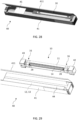
FIG. 1 is a plan view of a screening arrangement in an embodiment of the invention, mounted in a frame of a window; -
FIG. 2 is a perspective view of a screening arrangement in an embodiment of the invention, mounted in a frame of a roof window, and in a condition of use; -
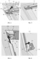
FIGS. 3 to 10 are partial perspective views of a screening arrangement in an embodiment of the invention during mounting in a frame of a roof window; -
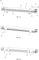
FIG. 11 is a perspective view of a screening arrangement in an embodiment of the invention; -
FIG. 12 is a view corresponding toFIG. 11 , of a further embodiment of the invention; -
FIG. 13 is a view corresponding toFIG. 11 , of an alternative embodiment of the invention; -
FIG. 14 is a partial perspective view, on a larger scale, of the screening arrangement ofFIG. 11 ; -
FIG. 15 is an exploded view of the details shown inFIG. 14 ; -
FIG. 16 is an end view of the embodiment ofFIG. 12 ; -
FIG. 17 is an end view of the embodiment ofFIG. 11 ; -
FIGS. 18 and 19 are perspective views of a cord holder in an embodiment of the screening arrangement, without and with a cord, respectively; -
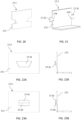
FIG. 20 is a perspective view of a cord holder in another embodiment of the screening arrangement; -
FIG. 21 is a perspective view of a cord holder in a still further embodiment of the screening arrangement; -
FIG. 22A is a plan view of a cord holder in yet another embodiment of the screening arrangement; -
FIG. 22B is an end view of the cord holder ofFIG. 22A ; -
FIGS. 23A and 23B are views corresponding toFIGS. 22A and 22B ; -
FIG. 24A is a plan view of a cord holder in still yet another embodiment of the screening arrangement; -
FIG. 24B is an end view of a top casing of the screening arrangement in a supply condition, with the cord holder ofFIG. 24A ; -
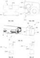
FIG. 25 is an exploded perspective view of a top casing of the screening arrangement, with a cord holder and a strap; -
FIG. 26 is a partial plan view of a strap in an alternative embodiment of the screening arrangement; -
FIG. 27 is a partial plan view of a strap in a further alternative embodiment of the screening arrangement; -
FIG. 28 is a perspective view of a screening arrangement in an embodiment of the invention, provided in a packaging in the supply condition; and -
FIG. 29 is a partial perspective, exploded view of the screening arrangement and packaging ofFIG. 28 . - In the following detailed description, preferred embodiments of the present invention will be described. However, it is to be understood that features of the different embodiments are exchangeable between the embodiments and may be combined in different ways, unless anything else is specifically indicated. It may also be noted that, for the sake of clarity, the dimensions of certain components illustrated in the drawings may differ from the corresponding dimensions in real-life implementations.
- It is noted that terms such as "up", "down", "left-hand", "right-hand", "exterior", "interior", "outer", "inner" are relative and refers to the viewpoint in question. By "front side" and "back side", respectively, are meant sides of elements facing the interior and the exterior, respectively. Correspondingly, terms such as "top", "bottom", "side" etc. denote the position of components in a mounted condition.
- Referring initially to
FIGS. 1 and 2 , an embodiment of a screening arrangement generally designated 10 is shown, mounted in aframe 2 representing a window. In the shown configuration, theframe 2 constitutes a pane-carrying sash of aroof window 1 and may be pivotable about a centre axis, or top-hung, relative to a stationary frame (not shown) of theroof window 1. - The
frame 2 may likewise be a stationary frame, which in a mounted position of the window lines an aperture in a building. It is noted that the term "frame" is to be understood as incorporating any substantially rectangular structure positioned in any opening in a building, whether in a wall or the roof, and surrounding anopening 3 to be screened. Thescreening arrangement 10 may thus be utilised in connection with e.g. windows having a frame only, windows having a sash frame and a stationary frame, or in doors. - In the present context, the
screening arrangement 10 will be described as an interior screening arrangement to be mounted on the interior side of a roof window, i.e., the side facing an inside room of a building, and in which theframe 2 is a pane-carrying sash connected to a stationary frame connected to a roof structure (not shown). - The
frame 2 has a top member 2.1, two mutually parallel side members 2.2, 2.3, and a bottom member 2.4, surrounding theopening 3 to be screened, covered by a suitable panel element such as insulating glazing in the form of apane 4. - The
screening arrangement 10 comprises a screening device including atop casing 11, abottom element 14, and ascreening body 15 having two side edges and a top and bottom portion. The top portion of thescreening body 15 is accommodated in thetop casing 11 and the bottom portion is fastened to thebottom element 14. The top portion of thescreening body 15 is typically fastened to a winding, folding, or rotating structure accommodated in thetop casing 11. In the embodiments to be described, thetop casing 11, thebottom profile 14, thescreening body 15, and a parallelguidance cord system 28 form a screening device constituting a roller blind, for instance a blackout roller blind. A roller assembly 20 (shown inFIG. 16 ) is provided, including a spring-biasedroller bar 21 on which thescreening body 15 is wound, and aguide bar 22 over which thescreening body 15 is guided. - The
screening body 15 is typically made from cloth or fabric, which is here flexible to allow rolling up. In principle, the screening body could be any feasible type for use in other screening devices such as roller screens, lamella blinds, curtains, and shades. If made by cloth or fabric, the screening body may be formed by a percentage of recycled or reused material which has proven to reduce the carbon footprint to a significant extent. The material and the manufacturing process may adhere to certified standards including OEKO-TEX® Standard 100 (2276-378) and STeP by OEKO-TEX® (22002567). - In the embodiment shown, the screening device of the
screening arrangement 10 comprises twoside rails frame 2 in the mounted condition. The side rails 12, 13 are also connected to thetop casing 11. - In
FIG. 1 , thescreening arrangement 10 is shown during a step of mounting. Here, thetop casing 11 has been connected to theframe 2 and is located at the top member 2.1 of theframe 2, parallel thereto. Thebottom element 14 is positioned in close proximity to thetop casing 11. The screening body 15 (not visible inFIG. 1 ) is accommodated in its entirety in thetop casing 11. Further elements indicated inFIG. 1 include the parallelguidance cord system 28 and atransportation assembly 16 comprising means for holding a set of cords of the parallelguidance cord system 28 as will be described in further detail below. - In
FIG. 2 , thescreening arrangement 10 is in a condition of use, in which thebottom element 14 is able to move to an arbitrary screening position thereby deploying thescreening body 15 to cover a desired portion of theopening 3. During the movement, the parallelguidance cord system 28 keeps thebottom element 14 parallel to thetop casing 11 at all times. This makes it possible for a user to grip thebottom element 14 at virtually any position along the length of thebottom element 14 and move thebottom element 14. - One example of a prior art screening arrangement with this functionality is shown and described in the embodiments of the above-mentioned
EP2412916B1 , and also in Applicant'sWO 2008/131757 A1 andWO 2008/131761 A1 . - Referring now to
FIGS. 3 to 11 , an embodiment of ascreening arrangement 10 of the present invention will be described in detail, including a description of how thescreening arrangement 10 is brought from a supply condition to a mounted condition. - Initially, reference is also briefly made to
FIGS. 28 and 29 , showing an example of apackaging 40 suitable for transportation and supply of thescreening arrangement 10. Thepackaging 40 comprises acardboard box 41 having a general form of a rectangular prism. Thecardboard box 41 may be provided from a blank and may as shown have anopenable lid 411. Thetop casing 11, thebottom element 14, and the screening body (not visible) form one unit together with the parallelguidance cord system 28 and thetransportation assembly 16 in thecardboard box 41. This unit is sub-packaged in end blocks 42, 43 which may be formed of a paper-based material such as folded cardboard, moulded pulp etc. One of or both end blocks 42, 43 may be temporarily fixated to the bottom of thecardboard box 41 so as to remain stationary relative to thecardboard box 41. Side rails 12, 13 are packaged in a sub-packaging 44 which may also be from a paper-based material such as folded cardboard. Since the height of roof windows is most often larger than the width, the side rails are typically the components dimensioning the length of thecardboard box 41, whereas the width and the height of thecardboard box 41 are typically constant throughout the size range of thescreening arrangements 10. Finally, a manual 45 is included in thepackaging 40 in the embodiment shown, containing installation guidance to the user in order to allow thescreening arrangement 10 to be brought from the supply condition to the mounted condition in which thescreening arrangement 10 is ready to assume a condition of use. - As shown in
FIG. 3 , thetop casing 11 comprises afront rail 114 defining a first direction corresponding to a width direction W, the first direction being perpendicular to a second direction corresponding to a height direction L. The first and second directions are perpendicular to a third direction corresponding to a depth direction D. - The
top casing 11 is configured to be mounted at the top member 2.1 of theframe 2. In the embodiment shown, thetop casing 11 is, at its longitudinal ends, provided with a set of end pieces 25 (shown inFIG. 11 ) comprising engagement means configured to be brought into engagement with a set of mountingbrackets 24 connected to the side members 2.2, 2.3 of theframe 2, near the top member 2.1. In case such mountingbrackets 24 are not pre-mounted on theframe 2, it is possible to order and fasten such mounting brackets separately. The unit comprising thetop casing 11, thebottom element 14, the screening body 15 (not visible), the parallelguidance cord system 28, and thetransportation assembly 16, is mounted in theframe 2 by moving the unit in the depth direction D to engage theend pieces 25 with the mountingbrackets 24. The position shown inFIG. 4 is now attained. - Referring now to
FIG. 5 , thetop casing 11 comprises a set ofangular brackets 26 at the longitudinal ends of thetop casing 11 configured to interact with a track in the side rails 12, 13. A counterpart track is typically provided on a back side of thefront rail 114. The side rails 12, 13 have a profile corresponding to thefront rail 114 of thetop casing 11 such that a U-shaped configuration with mitred joints is able to be formed. - To ensure proper sliding of the
bottom element 14 in the side rails 12, 13 when moving thebottom element 14 to a desired screening position in the condition of use, thebottom element 14 comprises a set ofside guidance elements 144 at the longitudinal ends of thebottom element 14 configured to interact with a track in the side rails 12, 13. - As shown in
FIG. 6 , thescreening arrangement 10 furthermore comprises a set offoot fittings 27 in the embodiment shown, connected to or connectable to the side members 2.2, 2.3 of theframe 2, near the bottom member 2.4. Typically, thefoot fittings 27 are not pre-mounted on theframe 2 but supplied with thescreening arrangement 10, for the user to fasten to the side members 2.2, 2.3 of theframe 2, here as indicated by a screw. - One after the other, the side rails 12, 13 are slid onto the respective
angular brackets 26 andside guidance elements 144 while moving the side rails 12, 13 upwards. Once engaged with thefoot fittings 27, the position of the side rails 12, 13 is adjusted such that the mitred top ends of the side rails 12, 13 are brought into contact with correspondingly mitred ends of thefront rail 114 of thetop casing 11. The side rails 12, 13 are, in the embodiment shown, mechanically fastened to the side members 2.2, 2.3 of theframe 2 by means of screws as indicated inFIG. 7 . - Throughout the above steps, from the supply condition to the condition shown in
FIG. 7 , which may be denoted an intermediate mounted condition, thetransportation assembly 16 has kept the cords of the parallelguidance cord system 28 stationary relative to thebottom element 14 and thetop casing 11. - To bring the
screening arrangement 10 from the intermediate mounted condition to a final mounted condition, the cords of the parallelguidance cord system 28 need to be brought into a position in which they form an H-formed configuration in a manner known per se, namely in that onecord 28a of the set of cords of the parallelguidance cord system 28 extends from a first longitudinal end of thetop casing 11 at one side member 2.2 (the right-hand side member in the drawings) through thebottom element 14, and to a position near the bottom member 2.4 at the other side member 2.3 (the left-hand side member of theframe 2, and theother cord 28b (cf.FIG. 11 ) extends in a mirror-inverted way, namely from a second longitudinal end of thetop casing 11 at the other side member 2.3, through thebottom element 14, and to a position near the bottom member 2.4 at the one side member 2.2. In the supply condition, the cords of the set ofcords bottom element 14, and the only cord readily accessible at the respective ends of thebottom profile 14 is the cord intended to be connected at the associated side member of theframe 2. - To keep the
cords guidance cord system 28 in place in the supply condition, thetransportation assembly 16 comprises a set ofcord holders 17. Referring now also toFIGS. 14 to 19 , eachcord holder 17 comprises a substantiallyplanar base 171 provided with cord holding means. Eachcord holder 17 is held in abutment with a front side of thebottom element 14 in the supply condition of thescreening arrangement 10. It is appreciated that onecord holder 17 is provided for eachcord guidance cord system 28. The left-hand and right-hand cord holders may be identical, or with variations. In the embodiments shown, thecord holders 17 are symmetric; however, it is possible to design the cord holders in a left-hand and a right-hand version. In the following, reference will be made to onecord holder 17. - The
cord holder 17 is made substantially from a paper-based material. One way of forming thecord holder 17 is from cardboard of a certain thickness, forinstance 2 to 5 mm, to allow the substantiallyplanar base 171 to be held in abutment with the front side of thebottom element 14 and to retain the associated cord, 28a or 28b, without rupturing or bending unintentionally. - In the embodiment shown in
FIGS. 14 to 19 , the cord holding means of thecord holder 17 comprise tworecesses 173, inopposite side edges base 171 of thecord holder 17. Locking means for thecord cut 174 in thebase 171, thecut 174 here adjoins therespective recess 173. - It is furthermore noted that the
bottom element 14 is positioned in close proximity, in the height direction L, to thetop casing 11 in the supply condition. By the term "close proximity", it is meant that the bottom element is located at or near the top casing in the supply condition. Typical ranges for any distance between the bottom element and the top casing are 0 to 10 mm, in particular 1 to 5 mm, including configurations in which one or more portions of thebottom element 14 overlap one or more portions of thetop casing 11. - In the embodiment shown, in which the
roller assembly 20 comprises a spring-biasedroller bar 21, thebottom element 14 will be pulled into its uppermost position relative to thetop casing 11 by means of the spring bias. A detailed description of the configuration of thetop casing 11 in the embodiment shown is given in Applicant's co-pending application published under No.EP4177437A1 . Elements shown inFIG. 16 but not described in further detail include atop portion 110 and acover 113 forming the back of thetop casing 11. Aflange portion 111 and atrack 112 provide connection of theend pieces 25. Finally, alight proofing element 30 is provided. - Thus, the
bottom element 14 assumes its uppermost position both in the supply condition, but also in a non-screening position in the condition of use. As shown inFIGS. 16 and 17 , atop edge 141 of thebottom element 14 is in the embodiment shown located substantially along abottom edge 114b of thefront rail 114 of thetop casing 11. - In the embodiment shown, the
cord holder 17 is substantially L-shaped comprising aleg 172 protruding from the base 171 at alower portion 171b thereof, theleg 172 abutting abottom edge 142 of thebottom element 14 in the supply condition. - In the supply condition of the
screening arrangement 10, anupper portion 171a of thebase 171 of thecord holder 17 is positioned between a back side of thefront rail 114 and the front side of thebottom element 14 and of thescreening body 15. In this position, thecord holder 17 is press-fit between the back side of thefront rail 114 and the front side of thebottom element 14. - By suitable dimensioning of the
cord holder 17 relative to thefront rail 114 and thebottom element 14, the press-fit may constitute the sole retention means to hold thecord holder 17 in abutment with the front side of thebottom element 14. This corresponds to the embodiment shown inFIG. 12 , in which the twocord holders 17 constitute the sole constituents of thetransportation assembly 16, or the embodiment ofFIG. 13 , in which straps 18 are provided, but not overlapping thecord holders 17. In the embodiment ofFIG. 13 , thestraps 18 function to hold thebottom element 14 and thetop casing 11 together in the supply condition, for instance no spring-bias is present to pull thebottom element 14 to its uppermost position. The enveloping effect could be obtained also by asingle strap 18, for instance placed at a central position in the width direction W. - The height of the
base 171 of thecord holder 17 will typically exceed the height of thebottom element 14 in order to ensure appropriate abutment with the front side of thebottom element 14, but a lower height is conceivable as well, in particular in the embodiment shown, in which thebottom element 14 has alongitudinal groove 143 into which a user can insert their fingers, or insert a tool, in the condition of use to operate thescreening arrangement 10. Alternative or additional retention means may then be provided if for instance flanges folded out from the base 171 are accommodated in thelongitudinal groove 143. This also reduces the risk of inadvertent skewing of thecord holders 17 on thebottom element 4. - In the embodiments in which two
straps 18 are provided to overlaprespective cord holders 17 at least partly, thestraps 18 also function as alternative or additional retention means to hold thecord holders 17 in abutment with the front side of thebottom element 14. - The
straps 18 are made from a paper-based material, wrapped around thetop casing 11 and thebottom element 14 about an axis parallel to the width direction W in the supply condition. - In the embodiments shown, in which the
straps 18 overlap thecord holders 17, thestraps 18 need to be broken before accessing thecord holders 17. Since the position of thetransportation assembly 16 close to thecords screening body 15, it is considered unsuitable to cut thestraps 18 by a knife or scissors. Hence, thestraps 18 need to be able to be torn manually. To this end, the strap or straps 18 is/are made from relative thin paper strip, for instance of banding paper. One example of a suitable commercially available product is TruePaper from manufacturer Ubro System Pac A/S. - Reverting now to
FIG. 8 , thescreening arrangement 10 is shown during the mounting step in which the left-hand strap 18 is torn. Thestrap 18 is then pulled out from behind thetop casing 11 and collected for recycling in an environmentally sustainable manner. Since thestrap 18 is paper-based, thestrap 18 allows recycling as high-grade paper-based material. - As shown in
FIG. 9 , thecord holder 17 with thecord 28a wound on the cord holding means provided by therecesses 173 in thebase 171 is subsequently removed from the abutment with the front side of thebottom element 14. Thecord 28a is unwound from thecord holder 17. In the embodiment shown, the free end of thecord 28a is provided with a cord end fitting 29a which fits into the foot fitting 27 as shown inFIG. 10 . Thecord holders 17 are then collected of for recycling, also as high-grade paper-based material. - The
screening arrangement 10 is now in its mounted condition. Thebottom element 14 is ready to be moved by a user to obtain a desired screening position. - Further alternative embodiments will now be described with reference to
FIGS. 20 to 27 . Only differences from the above embodiments will be described in detail. Elements having the same or analogous function as in the above embodiments are denoted by the same reference numerals. To distinguish, the cord holder of the embodiments are denoted 17.1, 17.2, ... and the strap 18.1, 18.2. - In the embodiment of
FIG. 20 , the cord holder 17.1 is composed of the base 171 including the cord holding means, that is, no leg is present. - In the embodiment of
FIG. 21 , the cord holding means of the cord holder 17.2 comprise at least one flange, here two flanges 17.21 protruding from arespective side edge base 171 of the cord holder 17.2. - In the embodiment of
FIGS. 22A and 22B , the cord holding means of the cord holder 17.3 comprise a flap 17.31 provided in thebase 171 and configured to be bent out of the plane of the base 171 to accommodate thecords guidance cord system 28 in the supply condition. - In the embodiment of
FIGS. 23A and 23B , the cord holding means of the cord holder 17.4 comprise two flaps 17.41, 17.42 provided in thebase 171 and configured to be bent out of the plane of the base 171 to accommodate thecords guidance cord system 28 in the supply condition. - In the embodiment of
FIGS. 24A and 24B , the cord holding means of the cord holder 17.5 comprises a flap 17.53 provided in thebase 171 and configured to be bent out of the plane of the base 171 to abut a front side of thefront rail 114 of thetop casing 11 in the supply condition. - Referring now to
FIG. 25 , thestrap 18 is formed by apaper band 180 with overlappingend portions strap 18 in the supply condition. If thepaper band 180 is made of a suitable material, such as the TruePaper mentioned in the above, the overlappingend portions FIG. 25 is the feature that thestrap 18 is provided with aweakening line 183 positioned outside the overlappingend portions paper band 180. The position is chosen such that the weakeningline 183 is accessible to a user during mounting of thescreening arrangement 10. - Alternative embodiments are shown in
FIGS. 26 and 27 , the strap 18.1, 18.2 comprises mechanical engagement means including interlocking slits 18.11, 18.12 as inFIG. 26 , or a slit 18.21 and a flap 18.22. - Combinations between the various embodiments are conceivable.
- Steps of an inventive method of mounting a screening arrangements as described in the above comprise the following:
- connecting the
top casing 11 to theframe 2 of theroof window 1, - removing the
cord holders 17 from the abutment with the front side of thebottom element 14, and - releasing the
cords cord holders 17, and connecting free ends of thecords frame 2 of theroof window 1, thereby attaining the mounted condition of thescreening arrangement 10. - Any side rails 12, 13 present in the screening arrangement are preferably connected to the
top casing 11 before the step of releasing thecord holders 17. - In a further aspect, an alternative method of mounting a screening arrangement from a supply condition to a mounted condition in a
frame 2 of aroof window 1 is provided. Referring to thescreening arrangement 10 described in the above embodiments, namely as comprising atop casing 11, abottom element 14, ascreening body 15, a parallelguidance cord system 28 comprising a set ofcords transportation assembly 16 comprising a set ofcord holders 17 of a paper-based material and provided with means for holding thecords top casing 11 and/or thebottom element 14, and at least onestrap 18 of a paper-based material wrapped around thetop casing 11 and thebottom element 14, the alternative method comprises the steps of: - connecting the
top casing 11 to theframe 2 of theroof window 1, - tearing the
straps 18, - removing the
straps 18 from thetop casing 11 by pulling one end of each tornstrap 18, - removing the
cord holders 17 from the abutment with the front side of thebottom element 14, and - releasing the
cords cord holders 17, and connecting free ends of thecords frame 2 of theroof window 1, thereby attaining the mounted condition of thescreening arrangement 10. - In case the
screening arrangement 10 furthermore comprises a set of side rails 12, 13, the side rails 12, 13 are connected to thetop casing 11 before the step of tearing thestraps 18 and releasing thecord holders 17. - Specific embodiments of the invention have now been described. However, several alternatives are possible, as would be apparent for someone skilled in the art.
- Such and other obvious modifications must be considered to be within the scope of the present invention, as it is defined by the appended claims.
-
- 1
- roof window
- 2
- frame
2.1 top member
2.2 side member
2.3 side member
2.4 bottom member - 3
- window opening
- 4
- pane
- 10
- screening arrangement
- 11
- top casing
110 top portion
111 flange portion
112 track
113 cover
114 front rail - 12
- side rail
- 13
- side rail
- 14
- bottom element
141 top edge
142 bottom edge
143 longitudinal groove
144 side guidance element - 15
- screening body
- 16
- retention means
- 17
- cord holder
171 base
171a upper portion
171b lower portion
171c side edge
171d side edge
172 leg
173 cord holding means / recess
174 cut - 17.1
- cord holder (alternative embodiment)
- 17.2
- cord holder (alternative embodiment)
17.21 flange - 17.3
- cord holder alternative embodiment)
17.31 flap - 17.4
- cord holder
- 18
- strap
180 paper band
181 overlapping end portion
182 overlapping end portion
183 weakening line - 18.1
- strap alternative embodiment
18.11 slit
18.12 slit - 18.2
- strap alternative embodiment)
18.21 slit
18.22 flap - 20
- roller assembly
- 21
- roller bar
- 22
- guide bar
- 24
- mounting bracket
- 25
- end piece
- 26
- angular bracket
- 27
- foot fitting
- 28
- parallel guidance cord system
- 28a
- cord
- 28b
- cord
- 29a
- cord end fitting
- 30
- light proofing element
- 40
- packaging
41 cardboard box
411 lid
42 end block
43 end block
44 sub-packaging
45 installation manual - L
- longitudinal direction
- W
- width direction
- D
- depth direction
- T
- arrow
Claims (19)
- A screening arrangement (10) for a roof window (1), said roof window comprising a frame (2) with a top member (2.1), a bottom member (2.4) and two mutually parallel side members (2.2, 2.3), the screening arrangement (10) being configured to assume a supply condition, a mounted condition in which the screening arrangement is mounted in the frame (2) of the roof window, and a condition of use, said screening arrangement comprising:a top casing (11) comprising a front rail (114) defining a first direction corresponding to a width direction (W), the first direction being perpendicular to a second direction corresponding to a height direction (L), the first and second directions being perpendicular to a third direction corresponding to a depth direction (D), said top casing (11) being configured to be mounted at the top member (2.1) of the frame (2),a bottom element (14) extending substantially in parallel with the top casing (11) and being movable relative to the top casing (11) in the height direction (L) in the condition of use,a screening body (15) having a top portion accommodated in the top casing (11) and a bottom portion fastened to the bottom element (14),a parallel guidance cord system (28) comprising a set of cords (28a, 28b), each cord (28a, 28b) being configured to extend from a first longitudinal end of the top casing (11) at one side member (2.2, 2.3), through the bottom element (14), and to a position near the bottom member (2.4) at the other side member (2.3, 2.2) of the frame (2) in the mounted condition, anda transportation assembly (16) comprising means for holding the cords (28a, 28b) of the parallel guidance cord system (28) in the supply condition of the screening arrangement (10),characterised in thatthe bottom element (14) is positioned in close proximity, in the height direction (L), to the top casing (11) in the supply condition, thatsaid transportation assembly comprises a set of cord holders (17), each cord holder (17) comprising a substantially planar base (171) provided with cord holding means and being held in abutment with a front side of the bottom element (14) in the supply condition of the screening arrangement (10), and in thateach cord holder (17) is made substantially from a paper-based material.
- A screening arrangement according to claim 1, wherein the bottom element (14) is provided with retention means for holding the cord holders (17) of the transportation assembly (16) in abutment with the front side of the bottom element (14)
- A screening arrangement according to any one of the preceding claims, wherein a top edge (141) of the bottom element (14) is located substantially along a bottom edge (114b) of the front rail (114) of the top casing (11) in the supply condition of the screening arrangement (10), and wherein an upper portion (171a) of the base (171) of the cord holder (17) is positioned between a back side of the front rail (114) and the front side of the bottom element (14) and of the screening body (15) such that the cord holder (17) is press-fit between the back side of the front rail (114) and the front side of the bottom element (14).
- A screening arrangement according to any one of the preceding claims, wherein the transportation assembly (16) comprises at least one strap (18) made from a paper-based material, wrapped around the top casing (11) and the bottom element (14) about an axis parallel to the width direction (W) in the supply condition the transportation assembly (16) preferably comprising two straps (18), more preferably positioned at or near respective cord holders (17) as seen in the width direction (W), more preferably such that each strap (18) overlaps at least a part of a respective cord holder (17).
- A screening arrangement according to claim 4, wherein each strap (18) is formed by a paper band (180) with overlapping end portions (181, 182) configured to be brought into engagement with each other to form a ring-shaped strap (18) in the supply condition, and wherein the overlapping end portions (181, 182) are sealed or welded together, or each strap (18.1, 18.2) comprises mechanical engagement means including interlocking slit(s) (18.11, 18.12; 18.21) and/or flap(s) (18.22).
- A screening arrangement according to any one of the preceding claims, wherein each strap (18) is provided with a weakening line (183) positioned outside the overlapping end portions (181, 182) of the paper band (180), preferably at such a position so as to be accessible to a user during mounting of the screening arrangement (10).
- A screening arrangement according to any one of the preceding claims, wherein the cord holder (17) is substantially L-shaped comprising a leg (172) protruding from the base (171) at a lower portion (171b) thereof, the leg (172) abutting a bottom edge (142) of the bottom element (14) in the supply condition.
- A screening arrangement according to any one of claims 1 to 6, wherein the cord holder (17.1) is composed of the base (171) including the cord holding means.
- A screening arrangement according to any one of the preceding claims, wherein the cord holding means of each cord holder (17) comprise at least one recess (173) in a side edge (171c, 171d) of the base (171) of the cord holder (17).
- A screening arrangement according to any one of the preceding claims, wherein the cord holding means of each cord holder (17.2) comprise at least one flange (17.21) protruding from a side edge (171c, 171d) of the base (171) of the cord holder (17.2).
- A screening arrangement according to any one of the preceding claims, wherein the cord holding means of each cord holder (17.3; 17.4) comprise at least one flap (17.31; 17.41, 17.42) provided in the base (171) and configured to be bent out of the plane of the base (171) to accommodate the cords (28a, 28b) of the parallel guidance cord system (28) in the supply condition.
- A screening arrangement according to any one of the preceding claims, wherein each cord holder (17.5) comprises at least one flap (17.53) provided in the base (171) and configured to be bent out of the plane of the base (171) to abut a front side of the front rail (114) of the top casing (11) in the supply condition.
- A screening arrangement according to any one of the preceding claims, wherein the cord holding means of each cord holder (17) comprise locking means for the cord (28a, 28b) of the parallel guidance cord system (28), preferably in the form of a cut (174) in the base (171), more preferably the cut (174) adjoins other portions of the cord holding means.
- A screening arrangement according to any one of the preceding claims, wherein the screening arrangement (10) furthermore comprises two side rails (12, 13) configured to be connected to the top casing (11) during mounting, the top casing (11) preferably comprising a set of angular brackets (26) at the longitudinal ends of the top casing (11) configured to interact with a track in the side rails (12, 13) the bottom element (14) more preferably comprising a set of side guidance elements (144) at the longitudinal ends of the bottom element (14) configured to interact with a track in the side rails (12, 13).
- A screening arrangement according to any one of the preceding claims, wherein the top casing (11) at its longitudinal ends is provided with a set of end pieces (25) comprising engagement means configured to be brought into engagement with a set of mounting brackets (24) connected to or connectable to the side members (2.2, 2.3) of the frame (2), near the top member (2.1), during mounting of the screening arrangement (10).
- A screening arrangement according to any one of the preceding claims, wherein a free end of each cord (28a, 28b) of the parallel guidance cord system (28) is provided with a cord end fitting (29a) configured to be brought into engagement with a set of foot fittings (27) connected to or connectable to the side members (2.2, 2.3) of the frame (2), near the bottom member (2.4), during mounting of the screening arrangement (10).
- A screening arrangement according to any one of the preceding claims, wherein the top casing (11), the bottom profile (14), the screening body (15), and the parallel guidance cord system (28) form a screening device constituting a roller blind, more preferably a blackout roller blind, and wherein a roller assembly (20) is accommodated in the top casing (11), the roller assembly (20) comprising a spring-biased roller bar (21) and preferably a guide bar (22).
- A method of mounting a screening arrangement according to any one of claims 1 to 17,
comprising the steps of:connecting the top casing (11) to the frame (2) of the roof window (1),removing the cord holders (17) from the abutment with the front side of the bottom element (14), andreleasing the cords (28a, 28b) from the cord holders (17), and connecting free ends of the cords (28a, 28b) to the frame (2) of the roof window (1), thereby attaining the mounted condition of the screening arrangement (10). - The method of claim 18, wherein the screening arrangement (10) furthermore comprises a set of side rails (12, 13), and wherein the side rails (12, 13) are connected to the top casing (11) before the step of releasing the cord holders (17).
Applications Claiming Priority (1)
| Application Number | Priority Date | Filing Date | Title |
|---|---|---|---|
| DKPA202370017 | 2023-01-13 |
Publications (2)
| Publication Number | Publication Date |
|---|---|
| EP4400689A1 true EP4400689A1 (en) | 2024-07-17 |
| EP4400689B1 EP4400689B1 (en) | 2025-10-01 |
Family
ID=89618924
Family Applications (1)
| Application Number | Title | Priority Date | Filing Date |
|---|---|---|---|
| EP24151427.2A Active EP4400689B1 (en) | 2023-01-13 | 2024-01-11 | Screening arrangement comprising a transportation assembly and method of mounting a screening arrangement |
Country Status (2)
| Country | Link |
|---|---|
| EP (1) | EP4400689B1 (en) |
| DK (1) | DK4400689T3 (en) |
Cited By (2)
| Publication number | Priority date | Publication date | Assignee | Title |
|---|---|---|---|---|
| EP4717871A1 (en) * | 2024-09-25 | 2026-04-01 | VKR Holding A/S | External screening arrangement comprising a return element and methods of mounting and dismounting an external screening arrangement |
| EP4717872A1 (en) * | 2024-09-25 | 2026-04-01 | VKR Holding A/S | External screening arrangement comprising a transportation assembly and method of mounting an external screening arrangement |
Citations (8)
| Publication number | Priority date | Publication date | Assignee | Title |
|---|---|---|---|---|
| WO2008131761A1 (en) | 2007-04-26 | 2008-11-06 | Vkr Holding A/S | A screening arrangement including a top element having a compact configuration |
| WO2008131757A1 (en) | 2007-04-26 | 2008-11-06 | Vkr Holding A/S | A screening arrangement having an end piece with an integrated roller shaft |
| EP2412916A2 (en) | 2007-10-26 | 2012-02-01 | VKR Holding A/S | A screening arrangement including a fitting for fixation, and method of mounting such a screening arrangement |
| US8205657B2 (en) * | 2006-06-09 | 2012-06-26 | Hunter Douglas Industries Bv | Covering and component parts thereof |
| JP2012241310A (en) * | 2011-05-13 | 2012-12-10 | Nichibei Co Ltd | Packaging method of rolling screen and rolling screen |
| EP2963228A1 (en) * | 2014-06-02 | 2016-01-06 | VKR Holding A/S | A screening arrangement with improved means for mounting |
| DE102018211634A1 (en) * | 2017-07-12 | 2019-01-17 | Centor Design Pty Ltd. | System and method for the transport and installation of a screening arrangement |
| EP4177437A1 (en) | 2021-11-03 | 2023-05-10 | VKR Holding A/S | Screening arrangement comprising a light-proofing element |
-
2024
- 2024-01-11 DK DK24151427.2T patent/DK4400689T3/en active
- 2024-01-11 EP EP24151427.2A patent/EP4400689B1/en active Active
Patent Citations (9)
| Publication number | Priority date | Publication date | Assignee | Title |
|---|---|---|---|---|
| US8205657B2 (en) * | 2006-06-09 | 2012-06-26 | Hunter Douglas Industries Bv | Covering and component parts thereof |
| WO2008131761A1 (en) | 2007-04-26 | 2008-11-06 | Vkr Holding A/S | A screening arrangement including a top element having a compact configuration |
| WO2008131757A1 (en) | 2007-04-26 | 2008-11-06 | Vkr Holding A/S | A screening arrangement having an end piece with an integrated roller shaft |
| EP2412916A2 (en) | 2007-10-26 | 2012-02-01 | VKR Holding A/S | A screening arrangement including a fitting for fixation, and method of mounting such a screening arrangement |
| EP2412916B1 (en) | 2007-10-26 | 2013-09-25 | VKR Holding A/S | A screening arrangement including a fitting for fixation, and method of mounting such a screening arrangement |
| JP2012241310A (en) * | 2011-05-13 | 2012-12-10 | Nichibei Co Ltd | Packaging method of rolling screen and rolling screen |
| EP2963228A1 (en) * | 2014-06-02 | 2016-01-06 | VKR Holding A/S | A screening arrangement with improved means for mounting |
| DE102018211634A1 (en) * | 2017-07-12 | 2019-01-17 | Centor Design Pty Ltd. | System and method for the transport and installation of a screening arrangement |
| EP4177437A1 (en) | 2021-11-03 | 2023-05-10 | VKR Holding A/S | Screening arrangement comprising a light-proofing element |
Cited By (2)
| Publication number | Priority date | Publication date | Assignee | Title |
|---|---|---|---|---|
| EP4717871A1 (en) * | 2024-09-25 | 2026-04-01 | VKR Holding A/S | External screening arrangement comprising a return element and methods of mounting and dismounting an external screening arrangement |
| EP4717872A1 (en) * | 2024-09-25 | 2026-04-01 | VKR Holding A/S | External screening arrangement comprising a transportation assembly and method of mounting an external screening arrangement |
Also Published As
| Publication number | Publication date |
|---|---|
| EP4400689B1 (en) | 2025-10-01 |
| DK4400689T3 (en) | 2025-12-01 |
Similar Documents
| Publication | Publication Date | Title |
|---|---|---|
| EP4400689B1 (en) | Screening arrangement comprising a transportation assembly and method of mounting a screening arrangement | |
| KR100441219B1 (en) | FIBER SECTOR FOR BODY SHEET AND METHOD AND DEVICE FOR PRODUCING THE SAME | |
| EP3700822B1 (en) | Method and system for creating custom-sized packaging boxes and for automatically packaging items | |
| KR102106421B1 (en) | Covering for architectural opening including cell structures biased to open and manufacturing method thereof | |
| KR100902366B1 (en) | Covering tubular slats for openings in buildings | |
| DE69605388T2 (en) | IMPROVED SLEEVE FOR AN INTERIOR COVERING AND METHOD FOR PRODUCING IT | |
| DK2748071T3 (en) | PACKAGING FOR A WINDOW AND PROCEDURE FOR PACKAGING | |
| KR200261897Y1 (en) | Vertical Type Blind | |
| MXPA05004684A (en) | Temporary window covering. | |
| EP2412916B1 (en) | A screening arrangement including a fitting for fixation, and method of mounting such a screening arrangement | |
| CA3234843A1 (en) | Reclosable bag having a repulpable zipper | |
| KR102351714B1 (en) | Eco-friendly paperroll withdrawal device | |
| AT17950U1 (en) | Wrapped skylight, vent louver mount and using a vent louver mount | |
| EP4412922B1 (en) | Packed roof window product, a method for packing a packed roof window product, and a method of unpacking a packed roof window product | |
| CA2317996C (en) | Flanged edge protector for window unit | |
| EP2220327B1 (en) | Screening arrangement including a fitting facilitating display of the screening body, and combination of a screening arrangement and a package improving display of the screening arrangement | |
| EP4717872A1 (en) | External screening arrangement comprising a transportation assembly and method of mounting an external screening arrangement | |
| EP4717871A1 (en) | External screening arrangement comprising a return element and methods of mounting and dismounting an external screening arrangement | |
| EP2140148B1 (en) | A method for fastening a screening body to a bottom element in a screening arrangement | |
| KR101982530B1 (en) | Method of joining sheet fabric for speed door | |
| AU2020403566B2 (en) | Child-resistant package | |
| GB2245253A (en) | Composite packaging blanks and methods of their manufacture | |
| ITMI940160U1 (en) | PERFECTED ELEMENT FOR ATTACKING ROLLER BELTS | |
| WO2025051828A1 (en) | Reusable transport container | |
| GB2394458A (en) | Covering for opening with base element used for packaging |
Legal Events
| Date | Code | Title | Description |
|---|---|---|---|
| PUAI | Public reference made under article 153(3) epc to a published international application that has entered the european phase |
Free format text: ORIGINAL CODE: 0009012 |
|
| STAA | Information on the status of an ep patent application or granted ep patent |
Free format text: STATUS: THE APPLICATION HAS BEEN PUBLISHED |
|
| AK | Designated contracting states |
Kind code of ref document: A1 Designated state(s): AL AT BE BG CH CY CZ DE DK EE ES FI FR GB GR HR HU IE IS IT LI LT LU LV MC ME MK MT NL NO PL PT RO RS SE SI SK SM TR |
|
| STAA | Information on the status of an ep patent application or granted ep patent |
Free format text: STATUS: REQUEST FOR EXAMINATION WAS MADE |
|
| 17P | Request for examination filed |
Effective date: 20250116 |
|
| GRAP | Despatch of communication of intention to grant a patent |
Free format text: ORIGINAL CODE: EPIDOSNIGR1 |
|
| STAA | Information on the status of an ep patent application or granted ep patent |
Free format text: STATUS: GRANT OF PATENT IS INTENDED |
|
| INTG | Intention to grant announced |
Effective date: 20250515 |
|
| GRAS | Grant fee paid |
Free format text: ORIGINAL CODE: EPIDOSNIGR3 |
|
| GRAA | (expected) grant |
Free format text: ORIGINAL CODE: 0009210 |
|
| STAA | Information on the status of an ep patent application or granted ep patent |
Free format text: STATUS: THE PATENT HAS BEEN GRANTED |
|
| AK | Designated contracting states |
Kind code of ref document: B1 Designated state(s): AL AT BE BG CH CY CZ DE DK EE ES FI FR GB GR HR HU IE IS IT LI LT LU LV MC ME MK MT NL NO PL PT RO RS SE SI SK SM TR |
|
| REG | Reference to a national code |
Ref country code: GB Ref legal event code: FG4D Ref country code: CH Ref legal event code: F10 Free format text: ST27 STATUS EVENT CODE: U-0-0-F10-F00 (AS PROVIDED BY THE NATIONAL OFFICE) Effective date: 20251001 |
|
| REG | Reference to a national code |
Ref country code: DE Ref legal event code: R096 Ref document number: 602024000754 Country of ref document: DE |
|
| REG | Reference to a national code |
Ref country code: IE Ref legal event code: FG4D |
|
| REG | Reference to a national code |
Ref country code: DK Ref legal event code: T3 Effective date: 20251126 |
|
| REG | Reference to a national code |
Ref country code: NL Ref legal event code: FP |
|
| PGFP | Annual fee paid to national office [announced via postgrant information from national office to epo] |
Ref country code: FR Payment date: 20251208 Year of fee payment: 3 |
|
| PGFP | Annual fee paid to national office [announced via postgrant information from national office to epo] |
Ref country code: IE Payment date: 20251209 Year of fee payment: 3 |
|
| PGFP | Annual fee paid to national office [announced via postgrant information from national office to epo] |
Ref country code: PL Payment date: 20251212 Year of fee payment: 3 |
|
| REG | Reference to a national code |
Ref country code: AT Ref legal event code: MK05 Ref document number: 1842673 Country of ref document: AT Kind code of ref document: T Effective date: 20251001 |
|
| PG25 | Lapsed in a contracting state [announced via postgrant information from national office to epo] |
Ref country code: ES Free format text: LAPSE BECAUSE OF FAILURE TO SUBMIT A TRANSLATION OF THE DESCRIPTION OR TO PAY THE FEE WITHIN THE PRESCRIBED TIME-LIMIT Effective date: 20251001 |
|
| REG | Reference to a national code |
Ref country code: LT Ref legal event code: MG9D |
|
| PG25 | Lapsed in a contracting state [announced via postgrant information from national office to epo] |
Ref country code: NO Free format text: LAPSE BECAUSE OF FAILURE TO SUBMIT A TRANSLATION OF THE DESCRIPTION OR TO PAY THE FEE WITHIN THE PRESCRIBED TIME-LIMIT Effective date: 20260101 |
|
| PGFP | Annual fee paid to national office [announced via postgrant information from national office to epo] |
Ref country code: DK Payment date: 20260113 Year of fee payment: 3 Ref country code: DE Payment date: 20251203 Year of fee payment: 3 |
|
| PG25 | Lapsed in a contracting state [announced via postgrant information from national office to epo] |
Ref country code: FI Free format text: LAPSE BECAUSE OF FAILURE TO SUBMIT A TRANSLATION OF THE DESCRIPTION OR TO PAY THE FEE WITHIN THE PRESCRIBED TIME-LIMIT Effective date: 20251001 Ref country code: HR Free format text: LAPSE BECAUSE OF FAILURE TO SUBMIT A TRANSLATION OF THE DESCRIPTION OR TO PAY THE FEE WITHIN THE PRESCRIBED TIME-LIMIT Effective date: 20251001 Ref country code: AT Free format text: LAPSE BECAUSE OF FAILURE TO SUBMIT A TRANSLATION OF THE DESCRIPTION OR TO PAY THE FEE WITHIN THE PRESCRIBED TIME-LIMIT Effective date: 20251001 |
|
| PG25 | Lapsed in a contracting state [announced via postgrant information from national office to epo] |
Ref country code: RS Free format text: LAPSE BECAUSE OF FAILURE TO SUBMIT A TRANSLATION OF THE DESCRIPTION OR TO PAY THE FEE WITHIN THE PRESCRIBED TIME-LIMIT Effective date: 20260101 |
|
| PG25 | Lapsed in a contracting state [announced via postgrant information from national office to epo] |
Ref country code: IS Free format text: LAPSE BECAUSE OF FAILURE TO SUBMIT A TRANSLATION OF THE DESCRIPTION OR TO PAY THE FEE WITHIN THE PRESCRIBED TIME-LIMIT Effective date: 20260201 |
|
| PG25 | Lapsed in a contracting state [announced via postgrant information from national office to epo] |
Ref country code: PT Free format text: LAPSE BECAUSE OF FAILURE TO SUBMIT A TRANSLATION OF THE DESCRIPTION OR TO PAY THE FEE WITHIN THE PRESCRIBED TIME-LIMIT Effective date: 20260202 Ref country code: CZ Free format text: LAPSE BECAUSE OF FAILURE TO SUBMIT A TRANSLATION OF THE DESCRIPTION OR TO PAY THE FEE WITHIN THE PRESCRIBED TIME-LIMIT Effective date: 20251001 |
|
| PG25 | Lapsed in a contracting state [announced via postgrant information from national office to epo] |
Ref country code: LV Free format text: LAPSE BECAUSE OF FAILURE TO SUBMIT A TRANSLATION OF THE DESCRIPTION OR TO PAY THE FEE WITHIN THE PRESCRIBED TIME-LIMIT Effective date: 20251001 |
|
| PG25 | Lapsed in a contracting state [announced via postgrant information from national office to epo] |
Ref country code: BG Free format text: LAPSE BECAUSE OF FAILURE TO SUBMIT A TRANSLATION OF THE DESCRIPTION OR TO PAY THE FEE WITHIN THE PRESCRIBED TIME-LIMIT Effective date: 20251001 |
|
| PG25 | Lapsed in a contracting state [announced via postgrant information from national office to epo] |
Ref country code: LT Free format text: LAPSE BECAUSE OF FAILURE TO SUBMIT A TRANSLATION OF THE DESCRIPTION OR TO PAY THE FEE WITHIN THE PRESCRIBED TIME-LIMIT Effective date: 20251001 |
|
| PG25 | Lapsed in a contracting state [announced via postgrant information from national office to epo] |
Ref country code: SM Free format text: LAPSE BECAUSE OF FAILURE TO SUBMIT A TRANSLATION OF THE DESCRIPTION OR TO PAY THE FEE WITHIN THE PRESCRIBED TIME-LIMIT Effective date: 20251001 |
|
| PG25 | Lapsed in a contracting state [announced via postgrant information from national office to epo] |
Ref country code: IT Free format text: LAPSE BECAUSE OF FAILURE TO SUBMIT A TRANSLATION OF THE DESCRIPTION OR TO PAY THE FEE WITHIN THE PRESCRIBED TIME-LIMIT Effective date: 20251001 |
|
| PG25 | Lapsed in a contracting state [announced via postgrant information from national office to epo] |
Ref country code: EE Free format text: LAPSE BECAUSE OF FAILURE TO SUBMIT A TRANSLATION OF THE DESCRIPTION OR TO PAY THE FEE WITHIN THE PRESCRIBED TIME-LIMIT Effective date: 20251001 |
|
| PG25 | Lapsed in a contracting state [announced via postgrant information from national office to epo] |
Ref country code: SK Free format text: LAPSE BECAUSE OF FAILURE TO SUBMIT A TRANSLATION OF THE DESCRIPTION OR TO PAY THE FEE WITHIN THE PRESCRIBED TIME-LIMIT Effective date: 20251001 |
|
| PG25 | Lapsed in a contracting state [announced via postgrant information from national office to epo] |
Ref country code: SE Free format text: LAPSE BECAUSE OF FAILURE TO SUBMIT A TRANSLATION OF THE DESCRIPTION OR TO PAY THE FEE WITHIN THE PRESCRIBED TIME-LIMIT Effective date: 20251001 |
|
| PLBE | No opposition filed within time limit |
Free format text: ORIGINAL CODE: 0009261 |
|
| STAA | Information on the status of an ep patent application or granted ep patent |
Free format text: STATUS: NO OPPOSITION FILED WITHIN TIME LIMIT |
|
| REG | Reference to a national code |
Ref country code: CH Ref legal event code: L10 Free format text: ST27 STATUS EVENT CODE: U-0-0-L10-L00 (AS PROVIDED BY THE NATIONAL OFFICE) Effective date: 20260812 |