EP4400682A1 - Hinge assembly and refrigeration device provided with same - Google Patents
Hinge assembly and refrigeration device provided with same Download PDFInfo
- Publication number
- EP4400682A1 EP4400682A1 EP22866560.0A EP22866560A EP4400682A1 EP 4400682 A1 EP4400682 A1 EP 4400682A1 EP 22866560 A EP22866560 A EP 22866560A EP 4400682 A1 EP4400682 A1 EP 4400682A1
- Authority
- EP
- European Patent Office
- Prior art keywords
- shaft
- hinge assembly
- slot
- hinge
- protrusion
- Prior art date
- Legal status (The legal status is an assumption and is not a legal conclusion. Google has not performed a legal analysis and makes no representation as to the accuracy of the status listed.)
- Pending
Links
Images




Classifications
-
- E—FIXED CONSTRUCTIONS
- E05—LOCKS; KEYS; WINDOW OR DOOR FITTINGS; SAFES
- E05D—HINGES OR SUSPENSION DEVICES FOR DOORS, WINDOWS OR WINGS
- E05D3/00—Hinges with pins
- E05D3/06—Hinges with pins with two or more pins
- E05D3/18—Hinges with pins with two or more pins with sliding pins or guides
-
- E—FIXED CONSTRUCTIONS
- E05—LOCKS; KEYS; WINDOW OR DOOR FITTINGS; SAFES
- E05D—HINGES OR SUSPENSION DEVICES FOR DOORS, WINDOWS OR WINGS
- E05D11/00—Additional features or accessories of hinges
- E05D11/06—Devices for limiting the opening movement of hinges
-
- E—FIXED CONSTRUCTIONS
- E05—LOCKS; KEYS; WINDOW OR DOOR FITTINGS; SAFES
- E05D—HINGES OR SUSPENSION DEVICES FOR DOORS, WINDOWS OR WINGS
- E05D5/00—Construction of single parts, e.g. the parts for attachment
- E05D5/02—Parts for attachment, e.g. flaps
- E05D5/06—Bent flaps
-
- E—FIXED CONSTRUCTIONS
- E05—LOCKS; KEYS; WINDOW OR DOOR FITTINGS; SAFES
- E05D—HINGES OR SUSPENSION DEVICES FOR DOORS, WINDOWS OR WINGS
- E05D7/00—Hinges or pivots of special construction
- E05D7/08—Hinges or pivots of special construction for use in suspensions comprising two spigots placed at opposite edges of the wing, especially at the top and the bottom, e.g. trunnions
- E05D7/081—Hinges or pivots of special construction for use in suspensions comprising two spigots placed at opposite edges of the wing, especially at the top and the bottom, e.g. trunnions the pivot axis of the wing being situated near one edge of the wing, especially at the top and bottom, e.g. trunnions
-
- F—MECHANICAL ENGINEERING; LIGHTING; HEATING; WEAPONS; BLASTING
- F25—REFRIGERATION OR COOLING; COMBINED HEATING AND REFRIGERATION SYSTEMS; HEAT PUMP SYSTEMS; MANUFACTURE OR STORAGE OF ICE; LIQUEFACTION SOLIDIFICATION OF GASES
- F25D—REFRIGERATORS; COLD ROOMS; ICE-BOXES; COOLING OR FREEZING APPARATUS NOT OTHERWISE PROVIDED FOR
- F25D23/00—General constructional features
- F25D23/02—Doors; Covers
-
- F—MECHANICAL ENGINEERING; LIGHTING; HEATING; WEAPONS; BLASTING
- F25—REFRIGERATION OR COOLING; COMBINED HEATING AND REFRIGERATION SYSTEMS; HEAT PUMP SYSTEMS; MANUFACTURE OR STORAGE OF ICE; LIQUEFACTION SOLIDIFICATION OF GASES
- F25D—REFRIGERATORS; COLD ROOMS; ICE-BOXES; COOLING OR FREEZING APPARATUS NOT OTHERWISE PROVIDED FOR
- F25D23/00—General constructional features
- F25D23/02—Doors; Covers
- F25D23/028—Details
-
- E—FIXED CONSTRUCTIONS
- E05—LOCKS; KEYS; WINDOW OR DOOR FITTINGS; SAFES
- E05Y—INDEXING SCHEME ASSOCIATED WITH SUBCLASSES E05D AND E05F, RELATING TO CONSTRUCTION ELEMENTS, ELECTRIC CONTROL, POWER SUPPLY, POWER SIGNAL OR TRANSMISSION, USER INTERFACES, MOUNTING OR COUPLING, DETAILS, ACCESSORIES, AUXILIARY OPERATIONS NOT OTHERWISE PROVIDED FOR, APPLICATION THEREOF
- E05Y2201/00—Constructional elements; Accessories therefor
- E05Y2201/60—Suspension or transmission members; Accessories therefor
- E05Y2201/622—Suspension or transmission members elements
- E05Y2201/682—Pins
-
- E—FIXED CONSTRUCTIONS
- E05—LOCKS; KEYS; WINDOW OR DOOR FITTINGS; SAFES
- E05Y—INDEXING SCHEME ASSOCIATED WITH SUBCLASSES E05D AND E05F, RELATING TO CONSTRUCTION ELEMENTS, ELECTRIC CONTROL, POWER SUPPLY, POWER SIGNAL OR TRANSMISSION, USER INTERFACES, MOUNTING OR COUPLING, DETAILS, ACCESSORIES, AUXILIARY OPERATIONS NOT OTHERWISE PROVIDED FOR, APPLICATION THEREOF
- E05Y2800/00—Details, accessories and auxiliary operations not otherwise provided for
- E05Y2800/26—Form or shape
- E05Y2800/266—Form or shape curved
-
- E—FIXED CONSTRUCTIONS
- E05—LOCKS; KEYS; WINDOW OR DOOR FITTINGS; SAFES
- E05Y—INDEXING SCHEME ASSOCIATED WITH SUBCLASSES E05D AND E05F, RELATING TO CONSTRUCTION ELEMENTS, ELECTRIC CONTROL, POWER SUPPLY, POWER SIGNAL OR TRANSMISSION, USER INTERFACES, MOUNTING OR COUPLING, DETAILS, ACCESSORIES, AUXILIARY OPERATIONS NOT OTHERWISE PROVIDED FOR, APPLICATION THEREOF
- E05Y2800/00—Details, accessories and auxiliary operations not otherwise provided for
- E05Y2800/26—Form or shape
- E05Y2800/292—Form or shape having apertures
- E05Y2800/296—Slots
-
- E—FIXED CONSTRUCTIONS
- E05—LOCKS; KEYS; WINDOW OR DOOR FITTINGS; SAFES
- E05Y—INDEXING SCHEME ASSOCIATED WITH SUBCLASSES E05D AND E05F, RELATING TO CONSTRUCTION ELEMENTS, ELECTRIC CONTROL, POWER SUPPLY, POWER SIGNAL OR TRANSMISSION, USER INTERFACES, MOUNTING OR COUPLING, DETAILS, ACCESSORIES, AUXILIARY OPERATIONS NOT OTHERWISE PROVIDED FOR, APPLICATION THEREOF
- E05Y2900/00—Application of doors, windows, wings or fittings thereof
- E05Y2900/30—Application of doors, windows, wings or fittings thereof for domestic appliances
- E05Y2900/31—Application of doors, windows, wings or fittings thereof for domestic appliances for refrigerators
Definitions
- the utility model relates to the technical field of home appliances, and in particular to a hinge assembly and refrigeration device having the same.
- a refrigeration device uses a single-axis hinge assembly, where a door performs a circular motion around a fixed axis of the hinge assembly, allowing the door to open at a large angle. At the same time, when the door is opened, a lateral side of the door occupy a certain space.
- An objective of the utility model is to provide a hinge assembly and refrigeration device having the same which can reduce a size of the hinge assembly and change a motion trajectory of the door to adapt to different application scenarios.
- an embodiment of the utility model provides a hinge assembly which includes a first hinge part and a second hinge part that cooperate with each other; the hinge assembly further includes a first shaft and a second shaft that are located on the first hinge part, and a fitting part located on the second hinge part, the fitting part includes a first fitting part and a second fitting part that are interconnected, when the hinge assembly is in an opening process, the first shaft moves at the first fitting part, and the second shaft moves at the second fitting part, when the hinge assembly is at a maximum opening angle, the first shaft is located at a stop end of the first fitting part, the stop end is located at the second fitting part.
- the fitting part is a slot
- the slot includes a first slot and a second slot that are interconnected, when the hinge assembly is in the opening process, the first shaft moves within the first slot, and the second shaft moves within the second slot, when the hinge assembly is at the maximum opening angle, the first shaft is located at a stop end of the first slot, the stop end is located within the second slot.
- a movement trajectory of the first shaft partially overlaps with a movement trajectory of the second shaft.
- the slot includes a first section, a middle section, and a second section that are sequentially connected, the first section together with the middle section forms the first slot, and the middle section together with the second section forms the second slot.
- the second hinge part rotates around a first rotational axis as a center axis relative to the first hinge part, the first rotational axis is a variable axis.
- the second hinge part rotates around a first rotational axis as a center axis relative to the first hinge part, the first rotational axis is a virtual axis.
- the second hinge part when the hinge assembly is opening from a closed state to a first opening angle, the second hinge part rotates around a first rotational axis as a center axis relative to the first hinge part, when the hinge assembly continues to be opened to the maximum opening angle from the first opening angle, the second hinge part rotates around a second rotational axis as a center axis relative to the first hinge part, the first rotational axis is different from the second rotational axis.
- the first rotational axis is a variable axis
- the second rotational axis is a fixed axis
- both the first rotational axis and the second rotational axis are virtual axes.
- the second slot is an arc slot with a central axis being a fixed axis.
- one of the first hinge part and the second hinge part is connected to a cabinet, and the other is connected to a door, the first shaft and the second shaft slide simultaneously within the slot to drive the door relative to the cabinet to produce a translational movement.
- the cabinet includes an accommodating chamber and a pivot side connected to the hinge assembly, when the hinge assembly is opened from a closed state to a first opening angle, the door moves from the pivot side towards the accommodating chamber.
- the second slot includes a beginning end and a final end, when the hinge assembly is in a closed state, the second shaft is located at the beginning end, and the first shaft is located at an end of the first slot far from the second slot, when the hinge assembly is opened from the closed state to the first opening angle, the first shaft moves within the first slot, driving the second shaft from the beginning end to the final end, and the door moves from the pivot side towards the accommodating chamber.
- the door includes a front wall away from the accommodating chamber and a side wall that is always sandwiched between the front wall and the accommodating chamber, the second hinge part is connected to the door, the beginning end is farther away from the front wall and the side wall compared to the final end.
- the second slot includes a beginning end and a final end
- the first slot includes a first part and a second part that are interconnected, when the hinge assembly is opened from the closed state to a first intermediate opening angle, the second shaft remains at the beginning end, and the first shaft moves within the first part around the second shaft as a central axis, when the hinge assembly is opened from the first intermediate opening angle to the first opening angle, the first shaft moves within the second part, driving the second shaft from the beginning end to the final end, and the door moves from the pivot side towards the accommodating chamber.
- one of the first hinge part and the second hinge part is connected to a cabinet, and the other is connected to a door, when the hinge assembly is opened from a closed state to a first opening angle, the first shaft and the second shaft slide simultaneously within the slot to drive the door relative to the cabinet to produce a translational movement, when the hinge assembly continues to be opened to the maximum opening angle from the first opening angle, the first shaft and the second shaft slide simultaneously within the slot to drive the door to rotate in suit.
- the cabinet includes an accommodating chamber and a pivot side connected to the hinge assembly
- the second slot includes a beginning end, a middle position, and a final end that are sequentially arranged, when the hinge assembly is in the closed state, the second shaft is located at the beginning end, and the first shaft is located at the end of the first slot far from the second slot, when the hinge assembly is opening from the closed state to the first opening angle, the first shaft moves within the first slot, driving the second shaft from the beginning end to the middle position, and the door moves from the pivot side towards the accommodating chamber, when the hinge assembly continues to be opened to the maximum opening angle from the first opening angle, the first shaft continues to move within the first slot, driving the second shaft from the middle position to the final end, and the door rotates in suit.
- the beginning end is located within the first slot.
- the fitting part is a protrusion
- the protrusion includes a first protrusion and second protrusion that are interconnected
- the first shaft includes a first notch that mates with the first protrusion
- the second shaft includes a second notch that mates with the second protrusion
- both the first protrusion and the second protrusion are elongated, the first notch is fitted on an outside of the first protrusion and slides along an extension direction of the first protrusion, and the second notch is fitted on tan outside of the second protrusion and slides along an extension direction of the second protrusion.
- the first shaft includes two first protruding columns, the two first protruding columns together form the first notch
- the second shaft includes two second protruding columns, the two second protruding columns together form the second notch.
- the first shaft further includes a first shaft main part connected to the first hinge part
- the second shaft further includes a second shaft main part connected to the first hinge part
- the two first protruding columns are located on a side of the first shaft main part away from the first hinge part
- the two second protruding columns are located on a side of the second shaft main part away from the first hinge part.
- the beneficial effects of an embodiment of the utility model include: the first fitting part and the second fitting part of this embodiment are interconnected, which can reduce a space occupied by an entire fitting part of the second hinge part, and an integrated fitting part is easy to mold. Additionally, the hinge assembly includes two shafts, which, compared to a single-axle hinge assembly, can change a motion trajectory of the door to adapt to different application scenarios.
- FIG. 1 for a schematic diagram of a refrigeration device 100 according to an embodiment of the utility model.
- the refrigeration device 100 includes a cabinet 10, a door 20, and a hinge assembly 30 connecting the cabinet 10 and the door 20.
- the refrigeration device 100 can be a refrigerator, freezer, wine cooler, etc., with the refrigeration device 100 being exemplified as a refrigerator here.
- the hinge assembly 30 is not only applicable to the refrigeration device 100 but can also be applied to other scenarios, such as cupboards, wardrobes, etc.
- the utility model is exemplified by an application of the hinge assembly 30 to the refrigerator 100 but is not limited to this.
- FIG. 2 a schematic diagram of the hinge assembly 30 with slots according to an embodiment of the utility model is shown.
- the hinge assembly 30 includes a first hinge part 31 and a second hinge part 32 that cooperate with each other.
- first hinge part 31 connects to either the cabinet 10 or the door 20, and the second hinge part 32 connects to the other.
- hinge parts refers to the hinge parts being independent components installed on the cabinet 10 or the door 20, or the hinge parts being directly integrated into the cabinet 10 or the door 20.
- the hinge assembly 30 also includes a first shaft 311 and a second shaft 312 located on the first hinge part 31, as well as a fitting part 40 located on the second hinge part 32.
- first shaft 311 and the second shaft 312 located on the first hinge part 31 means that the first shaft 311 and the second shaft 312 are set on the first hinge part 31.
- the first shaft 311 and the second shaft 312 can either be integrally formed with or assembled together with the first hinge part 31.
- the fitting part 40 includes a first fitting part 321 and a second fitting part 322 which are interconnected.
- the first shaft 311 moves at the first fitting part 321, and the second shaft 312 moves at the second fitting part 322.
- the hinge assembly 30 is at a maximum opening angle, the first shaft 311 is located at a stop end A1 of the first fitting part 321, and the stop end A1 is located at the second fitting part 322.
- the first fitting part 321 and the second fitting part 322 are interconnected, which can reduce a space occupied by an entire fitting part of the second hinge part 32, and an integrated fitting part 40 is easy to mold.
- the hinge assembly 30 includes two shafts. Compared to a single-axle hinge assembly, it can change a motion trajectory of the door 20 to adapt to different application scenarios.
- the fitting part 40 is exemplified as a slot 40 for explanation.
- the slot 40 can penetrate the second hinge part 32 in a thickness direction of the second hinge part 32, meaning the slot 40 is a through hole, or, the slot 40 can have a closed area on a side away from the first hinge part 31, meaning the slot 40 is a groove.
- the slot 40 includes a first slot 321 and a second slot 322 which are interconnected.
- first shaft 311 moves within the first slot 321
- second shaft 312 moves within the second slot 322.
- the slot 40 includes a first slot 321 and a second slot 322 which are interconnected" means that there is a direct connection between the first slot 321 and the second slot 322 without any gap, making the slot 40 a complete through structure.
- the hinge assembly 30 is in an opening process refers to the second hinge part 32 is opened away from the first hinge part 31, that is, actuating the second hinge part 32 in one direction to move away from the first hinge part 31.
- the opening process of the hinge assembly 30 corresponds to a opening process of the door 20.
- the first shaft 311 When the hinge assembly 30 is at a maximum opening angle, the first shaft 311 is located at a stop end A2 of the first slot 321, and the stop end A2 is located within the second slot 322.
- the hinge assembly 30 being at the maximum opening angle corresponds to the door 20 opening to a maximum opening angle
- the stop end A2 is located within the second slot 32" means that the stop end A2 is at an end or a middle position of the second slot 322.
- first slot 321 and the second slot 322 are interconnected, which can reduce a space occupied by av entire slot 40 of the second hinge part 32, and an integrated slot 40 is easy to mold, significantly reducing a molding process of the hinge assembly 30.
- the hinge assembly 30 in this embodiment includes two shafts. Compared to a single-axle hinge assembly, this embodiment can change a motion trajectory of the door to adapt to different application scenarios.
- a movement trajectory of the first shaft 311 partially overlaps with that of the second shaft 312.
- the movement trajectory of the first shaft 311 refers to all the movement paths of the first shaft 311 during an entire opening process of the hinge assembly 30 and the movement trajectory of the second shaft 312 refers to all the movement paths of the second shaft 312 during the entire opening process of the hinge assembly 30.
- Partially overlap means that during the entire opening process of the hinge assembly 30, the first shaft 311 passes through some areas that the second shaft 312 has passed through.
- the slot 40 has a section that is a shared area for both the first shaft 311 and the second shaft 312, effectively reducing an overall length of the slot 40 in an extension direction, thereby further reducing the space occupied by the entire slot 40 of the second hinge part 32.
- the slot 40 includes a first section L1, a middle section L2, and a second section L3 that are sequentially connected , with the first section L1 and the middle section L2 combined to form the first slot 321, and the middle section L2 and the second section L3 combined to form the second slot 322.
- the slot 40 is divided into three sequentially connected sections, with the middle section L2 being an overlapping area between the first slot 321 and the second slot 322.
- the first slot 321 includes a starting end A1 and a stopping end A2 set oppositely
- the second slot 322 includes a beginning end B1 and a final end B2 set oppositely.
- the first shaft 311 is located at the stopping end A2, which is between the beginning end B1 and the final end B2 of the second slot 322, meaning the stopping end A2 is in a middle area of the second slot 322.
- the slot 40 could be of other structures.
- a slot 40' includes a first slot 321' and a second slot 322' that are interconnected without an overlapping area.
- the first slot 321' includes a starting end A1 and a stopping end A2 set oppositely
- the second slot 322' includes a beginning end B1 and a final end B2 set oppositely.
- the hinge assembly 30' is at a maximum opening angle
- the first shaft 311' is located at the stopping end A2, which is at a junction area of the first slot 321' and the second slot 322', meaning the stopping end A2 is at an end of the second slot 322' and overlaps with the beginning end B1.
- the first rotational axis P1 is a variable axis and also a virtual axis.
- the first rotational axis P1 is a variable axis
- the first rotational axis P1 is not a fixed axis.
- a position of the first rotational axis P1 is always changing, meaning the relative position between the first rotational axis P1 and the cabinet 10 or the door 20 is variable.
- the first rotational axis P1 is a virtual axis
- the first rotational axis P1 is not an actual shaft present within the hinge assembly 30.
- the second hinge part 32 rotates around a second rotational axis P2 relative to the first hinge part 31, where the first rotational axis P1 and the second rotational axis P2 are different.
- the second hinge part 32 initially rotates relative to the first hinge part 31 around the first rotational axis P1 and then around the second rotational axis P2.
- the second rotational axis P2 is a fixed axis and also a virtual axis.
- the second rotational axis P2 is a fixed axis
- the position of the second rotational axis P2 is always fixed, meaning the relative position between the second rotational axis P2 and the cabinet 10 or the door 20 is fixed.
- the hinge assembly 30 may only include either the first rotational axis P1 or the second rotational axis P2.
- the forms of the first rotational axis P1 and the second rotational axis P2 are not limited to the description above; that is, the first rotational axis P1 and the second rotational axis P2 can be selected as a fixed axis, a non-fixed axis, a virtual axis, or a physical axis (the physical axis is defined as an actual component included in the hinge assembly 30) depending on the actual situation.
- both the first shaft 311 and the second shaft 312 rotate around the first rotational axis P1.
- the door 20 generates a translational movement relative to the cabinet 10
- the door 20 rotates relative to the cabinet 10
- the door 20 also moves horizontally relative to the cabinet 10, especially when applied to a refrigerator
- the translational movement refers to a horizontal movement; that is, in addition to rotate relative to the cabinet 10, the door 20 also generates horizontal movement relative to the cabinet 10.
- the cabinet 10 includes a accommodating chamber D and a pivot side P connected to a hinge assembly 30a.
- the hinge assembly 30a When the hinge assembly 30a is opened from a closed state to a first opening angle ⁇ 1, the door 20 moves from the pivot side P towards the accommodating chamber D.
- the accommodating chamber D refers to a compartment formed by an enclosure of the cabinet 10 for storing items
- the pivot side P refers to a side where the door 20 is hinged to the cabinet 10, with the movement towards the accommodating chamber D indicated as a left move in FIG. 14 .
- a second slot 322a includes a beginning end B1 and a final end B2.
- a second shaft 312a is at the beginning end B1
- a first shaft 311a is at the end of the first slot 321a far from a second slot 322a.
- the hinge assembly 30a is opened from the closed state to a first opening angle ⁇ 1
- the first shaft 311a moves within the first slot 321a, driving the second shaft 312 from the beginning end B1 to the final end B2, and the door 20 moves from the pivot side P towards the accommodating chamber D.
- a movement of the door 20 from the pivot side P towards the accommodating chamber D means the door 20 moves a certain distance away from the cupboard to avoid interference with the cupboard during the initial opening process.
- the door 20 includes a front wall 21 away from the accommodating chamber D and a side wall 22 that is always sandwiched between the front wall 21 and the accommodating chamber D.
- the beginning end B1 is farther away from the front wall 21 and the side wall 22 compared to the final end B2.
- the first opening angle ⁇ 1 is a maximum opening angle.
- the first shaft 311a moves from the starting end A1 to the stopping end A2, driving the second shaft 312a from the beginning end B1 to the final end B2, with the stopping end A2 overlapping with the beginning end B1, and the door 20 moves from the pivot side P towards the accommodating chamber D.
- the stopping end A2 may not overlap with the beginning end B1, for example, the stopping end A2 could be on a side of the beginning end B1 far from the final end B2.
- a second slot 322b includes a beginning end B1 and a final end B2.
- a first slot 321b includes a first part M1 and a second part M2 that are connected.
- the hinge assembly 30b When the hinge assembly 30b continues to be opened from the first intermediate opening angle ⁇ 11 to a first opening angle ⁇ 1, the first shaft 311b moves within the second part M2, driving the second shaft 312b from the beginning end B1 to the final end B2, and the door 20b moves from the pivot side P towards the accommodating chamber D.
- the door 20 first rotates in suit to a certain degree and then moves a certain distance away from a cupboard 200 to prevent interference with the cupboard 200 during an initial opening process.
- the first opening angle ⁇ 1 is a maximum opening angle.
- the first shaft 311b moves from the starting end A1 to the stopping end A2, driving the second shaft 312b from the beginning end B1 to the final end B2.
- the stopping end A2 overlaps with the beginning end B1, and the door 20 first rotates in suit, then moves from the pivot side P towards the accommodating chamber D.
- a hinge assembly 30c when a hinge assembly 30c is opened from a closed state to a first opening angle ⁇ 1, a second hinge part 32c rotates around a first rotational axis P1 relative to a first hinge part 31c, and both a first shaft 311c and a second shaft 312c slide within a slot 40c, driving the door 20 to generate a translational movement relative to the cabinet 10.
- the hinge assembly 30c When the hinge assembly 30c continues to be opened from the first opening angle ⁇ 1 to a maximum opening angle ⁇ 2, the second hinge part 32c rotates in suit around a second rotational axis P2 relative to the first hinge part 31c, and both the first shaft 311c and the second shaft 312c slide within the slot 40c, driving the door 20 to rotate in suit.
- a second slot 322c includes a beginning end B1, a middle position B3, and a final end B2 that are sequentially arranged.
- the hinge assembly 30c When the hinge assembly 30c is in a closed state, the second shaft 312c is at the beginning end B1, and the first shaft 311c is at the end of the first slot 321c far from the second slot 322c.
- the hinge assembly 30c When the hinge assembly 30c is opened from the closed state to the first opening angle ⁇ 1, the first shaft 311c moves within the first slot 321c, driving the second shaft 312c from the beginning end B1 to the middle position B2, and the door 20 moves from the pivot side P towards the accommodating chamber D.
- the hinge assembly 30c When the hinge assembly 30c continues to be opened from the first opening angle ⁇ 1 to the maximum opening angle ⁇ 2, the first shaft 311c continues to move within the first slot 321c, driving the second shaft 312c from the middle position B3 to the final end B2, and the door 20 rotates in suit.
- the first shaft 311c moves from the starting end A1 to the stopping end A2, driving the second shaft 312c from the beginning end B1 to the final end B2.
- the beginning end B1 is located within the first slot 321c, or in other words, the stopping end A2 is located within the second slot 322c, meaning there is an overlapping area between the first slot 321c and the second slot 322c.
- the door 20c first moves from the pivot side P towards the accommodating chamber D, and then continues to rotate in suit.
- the first shaft 311c is located within the second slot 322c.
- the first shaft 311c is precisely at the beginning end B1 of the second slot 322c.
- the second slot 322c is an arc slot with a central axis being a fixed axis, meaning at this time, both the first shaft 311c and the second shaft 312c move together within the second slot 322c around the second rotational axis P2, causing the door 20 to rotate in suit relative to the cabinet 10.
- the first shaft 311c could also be in different positions.
- the fitting part 40 is a protrusion located on the second hinge part 32d.
- the protrusion includes a first protrusion 321d and a second protrusion 322d that are interconnected.
- the first shaft 311d includes a first notch 313d that mates with the first protrusion 321d
- the second shaft 312d includes a second notch 314d that mates with the second protrusion 322d.
- the first protrusion 321d in this embodiment could also include a starting end, a stopping end, etc.
- the second protrusion 322d could include a beginning end, a middle position, and a final end, etc.
- the specifics can refer to the description of the first embodiment and will not be reiterated here.
- both the first protrusion 321d and the second protrusion 322d are elongated.
- the first notch 313d is fitted on an outside of the first protrusion 321d and slides along an extension direction of the first protrusion 321d.
- the second notch 314d is fitted on an outside of the second protrusion 322d and slides along an extension direction of the second protrusion 322d.
- an opening width of the first notch 313d is roughly the same as a width of the first protrusion 321d, ensuring that when the first notch 313d slides at the first protrusion 321d, it can stably slide along the extension direction of the first protrusion 321d without wobbling or disengaging. Moreover, a length of the first notch 313d in the extension direction of the first protrusion 321d is minimized to prevent interference between the first notch 313d and the first protrusion 321d during the sliding process.
- an opening width of the second notch 314d is roughly the same as a width of the second protrusion 322d, ensuring that when the second notch 314d slides at the second protrusion 322d, it can stably slide along the extension direction of the second protrusion 322d without wobbling or disengaging. Furthermore, a length of the second notch 314d in the extension direction of the second protrusion 322d is minimized to prevent interference between the second notch 314d and the second protrusion 322d during the sliding process.
- the ends of the first protrusion 321d and the second protrusion 322d are equipped with stoppers to prevent the first notch 313d and the second notch 314d from disengaging from the first protrusion 321d and the second protrusion 322d during the sliding process.
- the stoppers can be protrusions located at the ends of the first protrusion 321d and the second protrusion 322d or the ends of the first protrusion 321d and the second protrusion 322d could be bent to limit further sliding of the first notch 313d and the second notch 314d, but this is not limited to such configurations.
- the first shaft 311d includes two first protruding columns 3111d, which together form the first notch 313d.
- the second shaft 312d includes two second protruding columns 3121d, which together form the second notch 314d.
- both the first protruding columns 3111d and the second protruding columns 3121d are cylindrical.
- first notch 313d moves relative to the first protrusion 321d, it essentially means that the two first protruding columns 3111d slide on either side of the first protrusion 321d, reducing a friction between the first notch 313d and the first protrusion 321d and preventing the first notch 313d from getting stuck during the sliding process.
- the second notch 314d moves relative to the second protrusion 322d, it essentially means that the two second protruding columns 3121d slide on either side of the second protrusion 322d, reducing a friction between the second notch 314d and the second protrusion 322d and preventing the second notch 314d from getting stuck during the sliding process.
- the first shaft 311d also includes a first shaft main part 3112d connected to the first hinge part 31d
- the second shaft 312d also includes a second shaft main part 3122d connected to the first hinge part 31d.
- the two first protruding columns 3111d are located on a side of the first shaft main part 3112d away from the first hinge part 31d
- the two second protruding columns 3121d are located on a side of the second shaft main part 3122d away from the first hinge part 31d.
- the two first protruding columns 3111d and the two second protruding columns 3121d could directly connect to the first hinge part 31d.
Landscapes
- Engineering & Computer Science (AREA)
- Mechanical Engineering (AREA)
- Chemical & Material Sciences (AREA)
- Combustion & Propulsion (AREA)
- Physics & Mathematics (AREA)
- Thermal Sciences (AREA)
- General Engineering & Computer Science (AREA)
- Refrigerator Housings (AREA)
- Hinges (AREA)
Abstract
Description
- The present application claims the priority of the
Chinese patent application filed on September 9, 2021, with the application number 202122181198.6 - The utility model relates to the technical field of home appliances, and in particular to a hinge assembly and refrigeration device having the same.
- Currently, a refrigeration device uses a single-axis hinge assembly, where a door performs a circular motion around a fixed axis of the hinge assembly, allowing the door to open at a large angle. At the same time, when the door is opened, a lateral side of the door occupy a certain space.
- For instance, in recent years, with a progress of society and an improvement of people's living standards, a placement location and method of a refrigerator in home has become increasingly important to ordinary users. In line with current home decoration styles, some families pursue an integrated style, necessitating the embedding of refrigerators into cupboards to form what is called an embedded refrigerator device, suitable for integrated homes, smart homes, etc. These refrigerators are referred to as embedded refrigerators, and current refrigerators struggle to adapt to this type of embedded application scenario.
- In light of this, it is necessary to improve existing refrigerators to address the aforementioned issues.
- An objective of the utility model is to provide a hinge assembly and refrigeration device having the same which can reduce a size of the hinge assembly and change a motion trajectory of the door to adapt to different application scenarios.
- To achieve one of the purposes of the utility model, an embodiment of the utility model provides a hinge assembly which includes a first hinge part and a second hinge part that cooperate with each other; the hinge assembly further includes a first shaft and a second shaft that are located on the first hinge part, and a fitting part located on the second hinge part, the fitting part includes a first fitting part and a second fitting part that are interconnected, when the hinge assembly is in an opening process, the first shaft moves at the first fitting part, and the second shaft moves at the second fitting part, when the hinge assembly is at a maximum opening angle, the first shaft is located at a stop end of the first fitting part, the stop end is located at the second fitting part.
- As a further improvement of an embodiment of the utility model, the fitting part is a slot, the slot includes a first slot and a second slot that are interconnected, when the hinge assembly is in the opening process, the first shaft moves within the first slot, and the second shaft moves within the second slot, when the hinge assembly is at the maximum opening angle, the first shaft is located at a stop end of the first slot, the stop end is located within the second slot.
- As a further improvement of an embodiment of the utility model, a movement trajectory of the first shaft partially overlaps with a movement trajectory of the second shaft.
- As a further improvement of an embodiment of the utility model, the slot includes a first section, a middle section, and a second section that are sequentially connected, the first section together with the middle section forms the first slot, and the middle section together with the second section forms the second slot.
- As a further improvement of an embodiment of the utility model, the second hinge part rotates around a first rotational axis as a center axis relative to the first hinge part, the first rotational axis is a variable axis.
- As a further improvement of an embodiment of the utility model, the second hinge part rotates around a first rotational axis as a center axis relative to the first hinge part, the first rotational axis is a virtual axis.
- As a further improvement of an embodiment of the utility model, when the hinge assembly is opening from a closed state to a first opening angle, the second hinge part rotates around a first rotational axis as a center axis relative to the first hinge part, when the hinge assembly continues to be opened to the maximum opening angle from the first opening angle, the second hinge part rotates around a second rotational axis as a center axis relative to the first hinge part, the first rotational axis is different from the second rotational axis.
- As a further improvement of an embodiment of the utility model, the first rotational axis is a variable axis, and the second rotational axis is a fixed axis.
- As a further improvement of an embodiment of the utility model, both the first rotational axis and the second rotational axis are virtual axes.
- As a further improvement of an embodiment of the utility model, the second slot is an arc slot with a central axis being a fixed axis.
- As a further improvement of an embodiment of the utility model, one of the first hinge part and the second hinge part is connected to a cabinet, and the other is connected to a door, the first shaft and the second shaft slide simultaneously within the slot to drive the door relative to the cabinet to produce a translational movement.
- As a further improvement of an embodiment of the utility model, the cabinet includes an accommodating chamber and a pivot side connected to the hinge assembly, when the hinge assembly is opened from a closed state to a first opening angle, the door moves from the pivot side towards the accommodating chamber.
- As a further improvement of an embodiment of the utility model, the second slot includes a beginning end and a final end, when the hinge assembly is in a closed state, the second shaft is located at the beginning end, and the first shaft is located at an end of the first slot far from the second slot, when the hinge assembly is opened from the closed state to the first opening angle, the first shaft moves within the first slot, driving the second shaft from the beginning end to the final end, and the door moves from the pivot side towards the accommodating chamber.
- As a further improvement of an embodiment of the utility model, the door includes a front wall away from the accommodating chamber and a side wall that is always sandwiched between the front wall and the accommodating chamber, the second hinge part is connected to the door, the beginning end is farther away from the front wall and the side wall compared to the final end.
- As a further improvement of an embodiment of the utility model, the second slot includes a beginning end and a final end, and the first slot includes a first part and a second part that are interconnected, when the hinge assembly is opened from the closed state to a first intermediate opening angle, the second shaft remains at the beginning end, and the first shaft moves within the first part around the second shaft as a central axis, when the hinge assembly is opened from the first intermediate opening angle to the first opening angle, the first shaft moves within the second part, driving the second shaft from the beginning end to the final end, and the door moves from the pivot side towards the accommodating chamber.
- As a further improvement of an embodiment of the utility model, one of the first hinge part and the second hinge part is connected to a cabinet, and the other is connected to a door, when the hinge assembly is opened from a closed state to a first opening angle, the first shaft and the second shaft slide simultaneously within the slot to drive the door relative to the cabinet to produce a translational movement, when the hinge assembly continues to be opened to the maximum opening angle from the first opening angle, the first shaft and the second shaft slide simultaneously within the slot to drive the door to rotate in suit.
- As a further improvement of an embodiment of the utility model, the cabinet includes an accommodating chamber and a pivot side connected to the hinge assembly, the second slot includes a beginning end, a middle position, and a final end that are sequentially arranged, when the hinge assembly is in the closed state, the second shaft is located at the beginning end, and the first shaft is located at the end of the first slot far from the second slot, when the hinge assembly is opening from the closed state to the first opening angle, the first shaft moves within the first slot, driving the second shaft from the beginning end to the middle position, and the door moves from the pivot side towards the accommodating chamber, when the hinge assembly continues to be opened to the maximum opening angle from the first opening angle, the first shaft continues to move within the first slot, driving the second shaft from the middle position to the final end, and the door rotates in suit.
- As a further improvement of an embodiment of the utility model, the beginning end is located within the first slot.
- As a further improvement of an embodiment of the utility model, the fitting part is a protrusion, the protrusion includes a first protrusion and second protrusion that are interconnected, the first shaft includes a first notch that mates with the first protrusion, and the second shaft includes a second notch that mates with the second protrusion, when the hinge assembly is in the opening process, the first notch slides along the first protrusion and the second notch slides along the second protrusion, when the hinge assembly is at the maximum opening angle, the first notch is located at a stop end of the first protrusion, the stop end is located at the second protrusion.
- As a further improvement of an embodiment of the utility model, both the first protrusion and the second protrusion are elongated, the first notch is fitted on an outside of the first protrusion and slides along an extension direction of the first protrusion, and the second notch is fitted on tan outside of the second protrusion and slides along an extension direction of the second protrusion.
- As a further improvement of an embodiment of the utility model, the first shaft includes two first protruding columns, the two first protruding columns together form the first notch, the second shaft includes two second protruding columns, the two second protruding columns together form the second notch.
- As a further improvement of an embodiment of the utility model, the first shaft further includes a first shaft main part connected to the first hinge part, and the second shaft further includes a second shaft main part connected to the first hinge part, the two first protruding columns are located on a side of the first shaft main part away from the first hinge part, and the two second protruding columns are located on a side of the second shaft main part away from the first hinge part.
- Compared with the existing technology, the beneficial effects of an embodiment of the utility model include: the first fitting part and the second fitting part of this embodiment are interconnected, which can reduce a space occupied by an entire fitting part of the second hinge part, and an integrated fitting part is easy to mold. Additionally, the hinge assembly includes two shafts, which, compared to a single-axle hinge assembly, can change a motion trajectory of the door to adapt to different application scenarios.
-
-
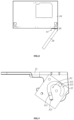
FIG. 1 is a perspective view of a refrigeration device in an embodiment of the utility model. -
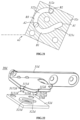
FIG. 2 is a perspective view of a hinge assembly in an embodiment of the utility model. -
FIG. 3 is an exploded view of the hinge assembly in an embodiment of the utility model. -
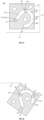
FIG. 4 is a cross-sectional view of a hinge assembly in another embodiment of the utility model. -
FIG. 5 is a top view of the refrigeration device in a closed state in an embodiment of the utility model. -
FIG. 6 is a schematic diagram of the hinge assembly in a closed state in an embodiment of the utility model. -
FIG. 7 is a cross-sectional view of the hinge assembly in the closed state in an embodiment of the utility model. -
FIG. 8 is a top view of the refrigeration device at a first opening angle in an embodiment of the utility model. -
FIG. 9 is a schematic diagram of the hinge assembly at a first opening angle in an embodiment of the utility model. -
FIG. 10 is a cross-sectional view of the hinge assembly at the first opening angle in an embodiment of the utility model. -
FIG. 11 is a top view of the refrigeration device at a maximum opening angle in an embodiment of the utility model. -
FIG. 12 is a schematic diagram of the hinge assembly at a maximum opening angle in an embodiment of the utility model. -
FIG. 13 is a cross-sectional view of the hinge assembly at the maximum opening angle in an embodiment of the utility model. -
FIG. 14 is a cross-sectional view of a hinge assembly in a closed state in a first specific example of the utility model. -
FIG. 15 is a cross-sectional view of the hinge assembly at a first opening angle in the first specific example of the utility model. -
FIG. 16 is a cross-sectional view of a hinge assembly in a closed state in a second specific example of the utility model. -
FIG. 17 is a cross-sectional view of the hinge assembly at a first intermediate opening angle in the second specific example of the utility model. -
FIG. 18 is a cross-sectional view of the hinge assembly at a first opening angle in the second specific example of the utility model. -
FIG. 19 is a cross-sectional view of a hinge assembly in a closed state in a third specific example of the utility model. -
FIG. 20 is a cross-sectional view of the hinge assembly at a first opening angle in the third specific example of the utility model. -
FIG. 21 is a cross-sectional view of the hinge assembly at a maximum opening angle in the third specific example of the utility model. -
FIG. 22 is an exploded view of a hinge assembly in a second embodiment of the utility model. - The following will provide a detailed description of the utility model with reference to specific embodiments shown in drawings. However, the embodiments do not limit the utility model; a structural, methodological, or functional modifications made by those of ordinary skill in the art based on the embodiments are all included within a scope of protection of the utility model.
- In various figures of the utility model, some dimensions of structures or parts are exaggerated relative to other structures or parts for a sake of illustration. Therefore, they are only used to illustrate a basic structure of a theme of the utility model.
- Refer to
FIG. 1 for a schematic diagram of arefrigeration device 100 according to an embodiment of the utility model. - The
refrigeration device 100 includes acabinet 10, adoor 20, and ahinge assembly 30 connecting thecabinet 10 and thedoor 20. - It should be noted that the
refrigeration device 100 can be a refrigerator, freezer, wine cooler, etc., with therefrigeration device 100 being exemplified as a refrigerator here. - Moreover, the
hinge assembly 30 is not only applicable to therefrigeration device 100 but can also be applied to other scenarios, such as cupboards, wardrobes, etc. The utility model is exemplified by an application of thehinge assembly 30 to therefrigerator 100 but is not limited to this. - Combining
FIG. 2 andFIG. 3 , a schematic diagram of thehinge assembly 30 with slots according to an embodiment of the utility model is shown. - The
hinge assembly 30 includes afirst hinge part 31 and asecond hinge part 32 that cooperate with each other. - Here, the
first hinge part 31 connects to either thecabinet 10 or thedoor 20, and thesecond hinge part 32 connects to the other. - It should be noted that a connection of hinge parts to the
cabinet 10 or thedoor 20 refers to the hinge parts being independent components installed on thecabinet 10 or thedoor 20, or the hinge parts being directly integrated into thecabinet 10 or thedoor 20. - The
hinge assembly 30 also includes afirst shaft 311 and asecond shaft 312 located on thefirst hinge part 31, as well as afitting part 40 located on thesecond hinge part 32. - Here, "the
first shaft 311 and thesecond shaft 312 located on thefirst hinge part 31" means that thefirst shaft 311 and thesecond shaft 312 are set on thefirst hinge part 31. Thefirst shaft 311 and thesecond shaft 312 can either be integrally formed with or assembled together with thefirst hinge part 31. The explanation of "located on" in other parts of the utility model can refer to the above description, which will not be reiterated subsequently. - The
fitting part 40 includes a firstfitting part 321 and a secondfitting part 322 which are interconnected. When thehinge assembly 30 is in a process of opening, thefirst shaft 311 moves at the firstfitting part 321, and thesecond shaft 312 moves at the secondfitting part 322. When thehinge assembly 30 is at a maximum opening angle, thefirst shaft 311 is located at a stop end A1 of the firstfitting part 321, and the stop end A1 is located at the secondfitting part 322. - In this embodiment, the first
fitting part 321 and the secondfitting part 322 are interconnected, which can reduce a space occupied by an entire fitting part of thesecond hinge part 32, and an integratedfitting part 40 is easy to mold. Additionally, thehinge assembly 30 includes two shafts. Compared to a single-axle hinge assembly, it can change a motion trajectory of thedoor 20 to adapt to different application scenarios. - In a first embodiment of the utility model, the
fitting part 40 is exemplified as aslot 40 for explanation. - The
slot 40 can penetrate thesecond hinge part 32 in a thickness direction of thesecond hinge part 32, meaning theslot 40 is a through hole, or, theslot 40 can have a closed area on a side away from thefirst hinge part 31, meaning theslot 40 is a groove. - The
slot 40 includes afirst slot 321 and asecond slot 322 which are interconnected. When thehinge assembly 30 is in an opening process, thefirst shaft 311 moves within thefirst slot 321, and thesecond shaft 312 moves within thesecond slot 322. - Here, the
first shaft 311 moves within the area defined by thefirst slot 321, and thesecond shaft 312 moves within the area defined by thesecond slot 322. "Theslot 40 includes afirst slot 321 and asecond slot 322 which are interconnected" means that there is a direct connection between thefirst slot 321 and thesecond slot 322 without any gap, making the slot 40 a complete through structure. - Furthermore, "the
hinge assembly 30 is in an opening process" refers to thesecond hinge part 32 is opened away from thefirst hinge part 31, that is, actuating thesecond hinge part 32 in one direction to move away from thefirst hinge part 31. When thehinge assembly 30 is installed on therefrigerator 100, the opening process of thehinge assembly 30 corresponds to a opening process of thedoor 20. - When the
hinge assembly 30 is at a maximum opening angle, thefirst shaft 311 is located at a stop end A2 of thefirst slot 321, and the stop end A2 is located within thesecond slot 322. - Here, the
hinge assembly 30 being at the maximum opening angle corresponds to thedoor 20 opening to a maximum opening angle, and "the stop end A2 is located within thesecond slot 32" means that the stop end A2 is at an end or a middle position of thesecond slot 322. - In this embodiment, the
first slot 321 and thesecond slot 322 are interconnected, which can reduce a space occupied by aventire slot 40 of thesecond hinge part 32, and anintegrated slot 40 is easy to mold, significantly reducing a molding process of thehinge assembly 30. - Additionally, the
hinge assembly 30 in this embodiment includes two shafts. Compared to a single-axle hinge assembly, this embodiment can change a motion trajectory of the door to adapt to different application scenarios. - In this embodiment, a movement trajectory of the
first shaft 311 partially overlaps with that of thesecond shaft 312. - Here, the movement trajectory of the
first shaft 311 refers to all the movement paths of thefirst shaft 311 during an entire opening process of thehinge assembly 30, and the movement trajectory of thesecond shaft 312 refers to all the movement paths of thesecond shaft 312 during the entire opening process of thehinge assembly 30. "Partially overlap" means that during the entire opening process of thehinge assembly 30, thefirst shaft 311 passes through some areas that thesecond shaft 312 has passed through. - Thus, the
slot 40 has a section that is a shared area for both thefirst shaft 311 and thesecond shaft 312, effectively reducing an overall length of theslot 40 in an extension direction, thereby further reducing the space occupied by theentire slot 40 of thesecond hinge part 32. - Specifically, the
slot 40 includes a first section L1, a middle section L2, and a second section L3 that are sequentially connected , with the first section L1 and the middle section L2 combined to form thefirst slot 321, and the middle section L2 and the second section L3 combined to form thesecond slot 322. - In other words, the
slot 40 is divided into three sequentially connected sections, with the middle section L2 being an overlapping area between thefirst slot 321 and thesecond slot 322. - In this embodiment, the
first slot 321 includes a starting end A1 and a stopping end A2 set oppositely, and thesecond slot 322 includes a beginning end B1 and a final end B2 set oppositely. When thehinge assembly 30 is at the maximum opening angle, thefirst shaft 311 is located at the stopping end A2, which is between the beginning end B1 and the final end B2 of thesecond slot 322, meaning the stopping end A2 is in a middle area of thesecond slot 322. - Of course, in other embodiments, the
slot 40 could be of other structures. - Combining with
FIG. 4 , a slot 40' includes a first slot 321' and a second slot 322' that are interconnected without an overlapping area. The first slot 321' includes a starting end A1 and a stopping end A2 set oppositely, and the second slot 322' includes a beginning end B1 and a final end B2 set oppositely. When the hinge assembly 30' is at a maximum opening angle, the first shaft 311' is located at the stopping end A2, which is at a junction area of the first slot 321' and the second slot 322', meaning the stopping end A2 is at an end of the second slot 322' and overlaps with the beginning end B1. - In this embodiment, combined with
FIG. 5 to FIG. 13 , when thehinge assembly 30 is opened from the closed state to a first opening angle α1, thesecond hinge part 32 rotates around a first rotational axis P1 relative to thefirst hinge part 31. - The first rotational axis P1 is a variable axis and also a virtual axis.
- Here, "the first rotational axis P1 is a variable axis" means that the first rotational axis P1 is not a fixed axis.
- That is, a position of the first rotational axis P1 is always changing, meaning the relative position between the first rotational axis P1 and the
cabinet 10 or thedoor 20 is variable. - Additionally, "the first rotational axis P1 is a virtual axis" indicates that the first rotational axis P1 is not an actual shaft present within the
hinge assembly 30. - When the
hinge assembly 30 continues to be opened from the first opening angle α1 to a maximum opening angle α2, thesecond hinge part 32 rotates around a second rotational axis P2 relative to thefirst hinge part 31, where the first rotational axis P1 and the second rotational axis P2 are different. - That is, during the entire opening process of the
hinge assembly 30, thesecond hinge part 32 initially rotates relative to thefirst hinge part 31 around the first rotational axis P1 and then around the second rotational axis P2. - In this embodiment, the second rotational axis P2 is a fixed axis and also a virtual axis.
- Here, "the second rotational axis P2 is a fixed axis" means that the position of the second rotational axis P2 is always fixed, meaning the relative position between the second rotational axis P2 and the
cabinet 10 or thedoor 20 is fixed. - In other embodiments, the
hinge assembly 30 may only include either the first rotational axis P1 or the second rotational axis P2. The forms of the first rotational axis P1 and the second rotational axis P2 are not limited to the description above; that is, the first rotational axis P1 and the second rotational axis P2 can be selected as a fixed axis, a non-fixed axis, a virtual axis, or a physical axis (the physical axis is defined as an actual component included in the hinge assembly 30) depending on the actual situation. - In this embodiment, continuing with
FIG. 5 to FIG. 13 , when thehinge assembly 30 is opening from the closed state to the first opening angle α1, thesecond hinge part 32 rotates around the first rotational axis P1 relative to thefirst hinge part 31, and both thefirst shaft 311 and thesecond shaft 312 slide within theslot 40, driving thedoor 20 to generate a translational movement relative to thecabinet 10. - That is, at this time, both the
first shaft 311 and thesecond shaft 312 rotate around the first rotational axis P1. - Here, "the
door 20 generates a translational movement relative to thecabinet 10" means that, when thedoor 20 rotates relative to thecabinet 10, thedoor 20 also moves horizontally relative to thecabinet 10, especially when applied to a refrigerator, the translational movement refers to a horizontal movement; that is, in addition to rotate relative to thecabinet 10, thedoor 20 also generates horizontal movement relative to thecabinet 10. - Below, various specific examples of the motion trajectory of the
door 20 are introduced. - In a first specific example, combined with
FIG. 14 and FIG. 15 , thecabinet 10 includes a accommodating chamber D and a pivot side P connected to ahinge assembly 30a. When thehinge assembly 30a is opened from a closed state to a first opening angle α1, thedoor 20 moves from the pivot side P towards the accommodating chamber D. - Here, the accommodating chamber D refers to a compartment formed by an enclosure of the
cabinet 10 for storing items, and the pivot side P refers to a side where thedoor 20 is hinged to thecabinet 10, with the movement towards the accommodating chamber D indicated as a left move inFIG. 14 . - Specifically, a
second slot 322a includes a beginning end B1 and a final end B2. When thehinge assembly 30a is in the closed state, asecond shaft 312a is at the beginning end B1, and afirst shaft 311a is at the end of thefirst slot 321a far from asecond slot 322a. When thehinge assembly 30a is opened from the closed state to a first opening angle α1, thefirst shaft 311a moves within thefirst slot 321a, driving thesecond shaft 312 from the beginning end B1 to the final end B2, and thedoor 20 moves from the pivot side P towards the accommodating chamber D. - That is, when there is a cupboard next to the refrigerator, a movement of the
door 20 from the pivot side P towards the accommodating chamber D means thedoor 20 moves a certain distance away from the cupboard to avoid interference with the cupboard during the initial opening process. - Here, the
door 20 includes afront wall 21 away from the accommodating chamber D and aside wall 22 that is always sandwiched between thefront wall 21 and the accommodating chamber D. When thesecond hinge part 32 is connected to thedoor 20, the beginning end B1 is farther away from thefront wall 21 and theside wall 22 compared to the final end B2. - It should be noted that in this specific example, the first opening angle α1 is a maximum opening angle. The
first shaft 311a moves from the starting end A1 to the stopping end A2, driving thesecond shaft 312a from the beginning end B1 to the final end B2, with the stopping end A2 overlapping with the beginning end B1, and thedoor 20 moves from the pivot side P towards the accommodating chamber D. - In other examples, the stopping end A2 may not overlap with the beginning end B1, for example, the stopping end A2 could be on a side of the beginning end B1 far from the final end B2.
- In a second specific example, combined with
FIG. 16 to FIG. 18 , asecond slot 322b includes a beginning end B1 and a final end B2. Afirst slot 321b includes a first part M1 and a second part M2 that are connected. When ahinge assembly 30b is opened from a closed state to a first intermediate opening angle α11, asecond shaft 312b remains at the beginning end B1, and afirst shaft 311b moves within the first part M1 centered around thesecond shaft 312b. When thehinge assembly 30b continues to be opened from the first intermediate opening angle α11 to a first opening angle α1, thefirst shaft 311b moves within the second part M2, driving thesecond shaft 312b from the beginning end B1 to the final end B2, and the door 20b moves from the pivot side P towards the accommodating chamber D. - That is, the
door 20 first rotates in suit to a certain degree and then moves a certain distance away from a cupboard 200 to prevent interference with the cupboard 200 during an initial opening process. - Here, in refrigerators with French doors or multi-door refrigerators that have a mullion, there are side-by-side left door and right door. Rotating the
door 20 in suit to a certain degree first can prevent interference between the left door and right door. - It should be noted that, in this specific example, the first opening angle α1 is a maximum opening angle. The
first shaft 311b moves from the starting end A1 to the stopping end A2, driving thesecond shaft 312b from the beginning end B1 to the final end B2. The stopping end A2 overlaps with the beginning end B1, and thedoor 20 first rotates in suit, then moves from the pivot side P towards the accommodating chamber D. - In a third specific example, combined with
FIG. 19 to FIG. 21 , when ahinge assembly 30c is opened from a closed state to a first opening angle α1, asecond hinge part 32c rotates around a first rotational axis P1 relative to afirst hinge part 31c, and both afirst shaft 311c and asecond shaft 312c slide within aslot 40c, driving thedoor 20 to generate a translational movement relative to thecabinet 10. When thehinge assembly 30c continues to be opened from the first opening angle α1 to a maximum opening angle α2, thesecond hinge part 32c rotates in suit around a second rotational axis P2 relative to thefirst hinge part 31c, and both thefirst shaft 311c and thesecond shaft 312c slide within theslot 40c, driving thedoor 20 to rotate in suit. - Specifically, a
second slot 322c includes a beginning end B1, a middle position B3, and a final end B2 that are sequentially arranged. When thehinge assembly 30c is in a closed state, thesecond shaft 312c is at the beginning end B1, and thefirst shaft 311c is at the end of thefirst slot 321c far from thesecond slot 322c. When thehinge assembly 30c is opened from the closed state to the first opening angle α1, thefirst shaft 311c moves within thefirst slot 321c, driving thesecond shaft 312c from the beginning end B1 to the middle position B2, and thedoor 20 moves from the pivot side P towards the accommodating chamber D. When thehinge assembly 30c continues to be opened from the first opening angle α1 to the maximum opening angle α2, thefirst shaft 311c continues to move within thefirst slot 321c, driving thesecond shaft 312c from the middle position B3 to the final end B2, and thedoor 20 rotates in suit. - It should be noted that, in this specific example, the
first shaft 311c moves from the starting end A1 to the stopping end A2, driving thesecond shaft 312c from the beginning end B1 to the final end B2. The beginning end B1 is located within thefirst slot 321c, or in other words, the stopping end A2 is located within thesecond slot 322c, meaning there is an overlapping area between thefirst slot 321c and thesecond slot 322c. The door 20c first moves from the pivot side P towards the accommodating chamber D, and then continues to rotate in suit. - In an example, when the
second shaft 312c moves from the middle position B3 to the final end B2, thefirst shaft 311c is located within thesecond slot 322c. For instance, when thesecond shaft 312c is at the middle position B3, thefirst shaft 311c is precisely at the beginning end B1 of thesecond slot 322c. Thesecond slot 322c is an arc slot with a central axis being a fixed axis, meaning at this time, both thefirst shaft 311c and thesecond shaft 312c move together within thesecond slot 322c around the second rotational axis P2, causing thedoor 20 to rotate in suit relative to thecabinet 10. - Of course, in other examples, when the
second shaft 312c is at the middle position B3, thefirst shaft 311c could also be in different positions. - In a second embodiment of the utility model, combined with
FIG. 22 , thefitting part 40 is a protrusion located on thesecond hinge part 32d. The protrusion includes afirst protrusion 321d and asecond protrusion 322d that are interconnected. Thefirst shaft 311d includes afirst notch 313d that mates with thefirst protrusion 321d, and thesecond shaft 312d includes asecond notch 314d that mates with thesecond protrusion 322d. When thehinge assembly 30d is in the opening process, thefirst notch 313d slides along thefirst protrusion 321d, and thesecond notch 314d slides along thesecond protrusion 322d. When thehinge assembly 30d is at a maximum opening angle, thefirst notch 313d is located at a stop end of thefirst protrusion 321d, which is located at thesecond protrusion 314d. - It should be noted that, similar to the first embodiment, the
first protrusion 321d in this embodiment could also include a starting end, a stopping end, etc., and thesecond protrusion 322d could include a beginning end, a middle position, and a final end, etc. The specifics can refer to the description of the first embodiment and will not be reiterated here. - In this embodiment, both the
first protrusion 321d and thesecond protrusion 322d are elongated. Thefirst notch 313d is fitted on an outside of thefirst protrusion 321d and slides along an extension direction of thefirst protrusion 321d. Similarly, thesecond notch 314d is fitted on an outside of thesecond protrusion 322d and slides along an extension direction of thesecond protrusion 322d. - Here, an opening width of the
first notch 313d is roughly the same as a width of thefirst protrusion 321d, ensuring that when thefirst notch 313d slides at thefirst protrusion 321d, it can stably slide along the extension direction of thefirst protrusion 321d without wobbling or disengaging. Moreover, a length of thefirst notch 313d in the extension direction of thefirst protrusion 321d is minimized to prevent interference between thefirst notch 313d and thefirst protrusion 321d during the sliding process. - Similarly, an opening width of the
second notch 314d is roughly the same as a width of thesecond protrusion 322d, ensuring that when thesecond notch 314d slides at thesecond protrusion 322d, it can stably slide along the extension direction of thesecond protrusion 322d without wobbling or disengaging. Furthermore, a length of thesecond notch 314d in the extension direction of thesecond protrusion 322d is minimized to prevent interference between thesecond notch 314d and thesecond protrusion 322d during the sliding process. - The ends of the
first protrusion 321d and thesecond protrusion 322d are equipped with stoppers to prevent thefirst notch 313d and thesecond notch 314d from disengaging from thefirst protrusion 321d and thesecond protrusion 322d during the sliding process. - Here, the stoppers can be protrusions located at the ends of the
first protrusion 321d and thesecond protrusion 322d or the ends of thefirst protrusion 321d and thesecond protrusion 322d could be bent to limit further sliding of thefirst notch 313d and thesecond notch 314d, but this is not limited to such configurations. - In this embodiment, the
first shaft 311d includes two first protrudingcolumns 3111d, which together form thefirst notch 313d. Similarly, thesecond shaft 312d includes two second protrudingcolumns 3121d, which together form thesecond notch 314d. - Here, both the first protruding
columns 3111d and the second protrudingcolumns 3121d are cylindrical. - Thus, when the
first notch 313d moves relative to thefirst protrusion 321d, it essentially means that the two first protrudingcolumns 3111d slide on either side of thefirst protrusion 321d, reducing a friction between thefirst notch 313d and thefirst protrusion 321d and preventing thefirst notch 313d from getting stuck during the sliding process. - Similarly, when the
second notch 314d moves relative to thesecond protrusion 322d, it essentially means that the two second protrudingcolumns 3121d slide on either side of thesecond protrusion 322d, reducing a friction between thesecond notch 314d and thesecond protrusion 322d and preventing thesecond notch 314d from getting stuck during the sliding process. - In this embodiment, the
first shaft 311d also includes a first shaftmain part 3112d connected to thefirst hinge part 31d, and thesecond shaft 312d also includes a second shaftmain part 3122d connected to thefirst hinge part 31d. The two first protrudingcolumns 3111d are located on a side of the first shaftmain part 3112d away from thefirst hinge part 31d, and the two second protrudingcolumns 3121d are located on a side of the second shaftmain part 3122d away from thefirst hinge part 31d. - Of course, in other embodiments, the two first protruding
columns 3111d and the two second protrudingcolumns 3121d could directly connect to thefirst hinge part 31d. - Other explanations of this embodiment can refer to the first embodiment and will not be reiterated here.
- The above embodiments are only intended to illustrate technical solutions of the utility model and not to limit it. Although the utility model has been described in detail with reference to preferable embodiments, for example, if technologies of different embodiments can be superimposed to achieve corresponding effects, such schemes are also within a protection scope of the utility model. Those skilled in the art should understand that modifications or equivalent substitutions can be made to the technical solutions of the utility model without departing from a spirit and scope of the technical solutions of the utility model.
Claims (23)
- A hinge assembly, characterized in that it comprises a first hinge part and a second hinge part that cooperate with each other; the hinge assembly further comprises a first shaft and a second shaft that are located on the first hinge part, and a fitting part located on the second hinge part, the fitting part comprises a first fitting part and a second fitting part that are interconnected, when the hinge assembly is in an opening process, the first shaft moves at the first fitting part, and the second shaft moves at the second fitting part, when the hinge assembly is at a maximum opening angle, the first shaft is located at a stop end of the first fitting part, the stop end is located at the second fitting part.
- The hinge assembly according to claim 1, characterized in that the fitting part is a slot, the slot comprises a first slot and a second slot that are interconnected, when the hinge assembly is in the opening process, the first shaft moves within the first slot, and the second shaft moves within the second slot, when the hinge assembly is at the maximum opening angle, the first shaft is located at a stop end of the first slot, the stop end is located within the second slot.
- The hinge assembly according to claim 2, characterized in that a movement trajectory of the first shaft partially overlaps with a movement trajectory of the second shaft.
- The hinge assembly according to claim 2, characterized in that the slot comprises a first section, a middle section, and a second section that are sequentially connected, the first section together with the middle section forms the first slot, and the middle section together with the second section forms the second slot.
- The hinge assembly according to claim 2, characterized in that the second hinge part rotates around a first rotational axis as a center axis relative to the first hinge part, the first rotational axis is a variable axis.
- The hinge assembly according to claim 2, characterized in that the second hinge part rotates around a first rotational axis as a center axis relative to the first hinge part, the first rotational axis is a virtual axis.
- The hinge assembly according to claim 2, characterized in that, when the hinge assembly is opening from a closed state to a first opening angle, the second hinge part rotates around a first rotational axis as a center axis relative to the first hinge part, when the hinge assembly continues to be opened to the maximum opening angle from the first opening angle, the second hinge part rotates around a second rotational axis as a center axis relative to the first hinge part, the first rotational axis is different from the second rotational axis.
- The hinge assembly according to claim 7, characterized in that the first rotational axis is a variable axis, and the second rotational axis is a fixed axis.
- The hinge assembly according to claim 7, characterized in that both the first rotational axis and the second rotational axis are virtual axes.
- The hinge assembly according to claim 2, characterized in that the second slot is an arc slot with a central axis being a fixed axis.
- The hinge assembly according to claim 2, characterized in that one of the first hinge part and the second hinge part is connected to a cabinet, and the other is connected to a door, the first shaft and the second shaft slide simultaneously within the slot to drive the door relative to the cabinet to produce a translational movement.
- The hinge assembly according to claim 11, characterized in that the cabinet comprises an accommodating chamber and a pivot side connected to the hinge assembly, when the hinge assembly is opened from a closed state to a first opening angle, the door moves from the pivot side towards the accommodating chamber.
- The hinge assembly according to claim 12, characterized in that the second slot comprises a beginning end and a final end, when the hinge assembly is in a closed state, the second shaft is located at the beginning end, and the first shaft is located at an end of the first slot far from the second slot, when the hinge assembly is opened from the closed state to the first opening angle, the first shaft moves within the first slot, driving the second shaft from the beginning end to the final end, and the door moves from the pivot side towards the accommodating chamber.
- The hinge assembly according to claim 13, characterized in that the door comprises a front wall away from the accommodating chamber and a side wall that is always sandwiched between the front wall and the accommodating chamber, the second hinge part is connected to the door, the beginning end is farther away from the front wall and the side wall compared to the final end.
- The hinge assembly according to claim 12, characterized in that the second slot comprises a beginning end and a final end, and the first slot comprises a first part and a second part that are interconnected, when the hinge assembly is opened from the closed state to a first intermediate opening angle, the second shaft remains at the beginning end, and the first shaft moves within the first part around the second shaft as a central axis, when the hinge assembly is opened from the first intermediate opening angle to the first opening angle, the first shaft moves within the second part, driving the second shaft from the beginning end to the final end, and the door moves from the pivot side towards the accommodating chamber.
- The hinge assembly according to claim 2, characterized in that one of the first hinge part and the second hinge part is connected to a cabinet, and the other is connected to a door, when the hinge assembly is opened from a closed state to a first opening angle, the first shaft and the second shaft slide simultaneously within the slot to drive the door relative to the cabinet to produce a translational movement, when the hinge assembly continues to be opened to the maximum opening angle from the first opening angle, the first shaft and the second shaft slide simultaneously within the slot to drive the door to rotate in suit.
- The hinge assembly according to claim 16, characterized in that the cabinet comprises an accommodating chamber and a pivot side connected to the hinge assembly, the second slot comprises a beginning end, a middle position, and a final end that are sequentially arranged, when the hinge assembly is in the closed state, the second shaft is located at the beginning end, and the first shaft is located at the end of the first slot far from the second slot, when the hinge assembly is opening from the closed state to the first opening angle, the first shaft moves within the first slot, driving the second shaft from the beginning end to the middle position, and the door moves from the pivot side towards the accommodating chamber, when the hinge assembly continues to be opened to the maximum opening angle from the first opening angle, the first shaft continues to move within the first slot, driving the second shaft from the middle position to the final end, and the door rotates in suit.
- The hinge assembly according to claim 17, characterized in that the beginning end is located within the first slot.
- The hinge assembly according to claim 1, characterized in that the fitting part is a protrusion, the protrusion comprises a first protrusion and second protrusion that are interconnected, the first shaft comprises a first notch that mates with the first protrusion, and the second shaft comprises a second notch that mates with the second protrusion, when the hinge assembly is in the opening process, the first notch slides along the first protrusion and the second notch slides along the second protrusion, when the hinge assembly is at the maximum opening angle, the first notch is located at a stop end of the first protrusion, the stop end is located at the second protrusion.
- The hinge assembly according to claim 19, characterized in that both the first protrusion and the second protrusion are elongated, the first notch is fitted on an outside of the first protrusion and slides along an extension direction of the first protrusion, and the second notch is fitted on tan outside of the second protrusion and slides along an extension direction of the second protrusion.
- The hinge assembly according to claim 19, characterized in that the first shaft comprises two first protruding columns, the two first protruding columns together form the first notch, the second shaft comprises two second protruding columns, the two second protruding columns together form the second notch.
- The hinge assembly according to claim 21, characterized in that the first shaft further comprises a first shaft main part connected to the first hinge part, and the second shaft further comprises a second shaft main part connected to the first hinge part, the two first protruding columns are located on a side of the first shaft main part away from the first hinge part, and the two second protruding columns are located on a side of the second shaft main part away from the first hinge part.
- A refrigeration device, characterized in that it comprises a cabinet, a door, and a hinge assembly connecting the cabinet and the door, the hinge assembly is any one of the hinge assembly according to claims 1-22.
Applications Claiming Priority (2)
| Application Number | Priority Date | Filing Date | Title |
|---|---|---|---|
| CN202122181198.6U CN216110239U (en) | 2021-09-09 | 2021-09-09 | Hinge assembly and refrigeration equipment with same |
| PCT/CN2022/117151 WO2023036097A1 (en) | 2021-09-09 | 2022-09-06 | Hinge assembly and refrigeration device provided with same |
Publications (2)
| Publication Number | Publication Date |
|---|---|
| EP4400682A1 true EP4400682A1 (en) | 2024-07-17 |
| EP4400682A4 EP4400682A4 (en) | 2024-12-04 |
Family
ID=80732454
Family Applications (1)
| Application Number | Title | Priority Date | Filing Date |
|---|---|---|---|
| EP22866560.0A Pending EP4400682A4 (en) | 2021-09-09 | 2022-09-06 | Hinge assembly and refrigeration device provided with same |
Country Status (3)
| Country | Link |
|---|---|
| EP (1) | EP4400682A4 (en) |
| CN (1) | CN216110239U (en) |
| WO (1) | WO2023036097A1 (en) |
Cited By (1)
| Publication number | Priority date | Publication date | Assignee | Title |
|---|---|---|---|---|
| EP4707513A1 (en) * | 2024-09-06 | 2026-03-11 | LG Electronics Inc. | Home appliance |
Families Citing this family (7)
| Publication number | Priority date | Publication date | Assignee | Title |
|---|---|---|---|---|
| CN216110239U (en) * | 2021-09-09 | 2022-03-22 | 青岛海尔电冰箱有限公司 | Hinge assembly and refrigeration equipment with same |
| CN115807605A (en) * | 2021-09-15 | 2023-03-17 | 青岛海尔电冰箱有限公司 | Hinge and built-in refrigerator with the hinge |
| CN117190594B (en) * | 2022-05-30 | 2026-04-07 | 海信冰箱有限公司 | Refrigerator with a refrigerator body |
| CN118273605B (en) * | 2022-12-30 | 2025-09-16 | 海信冰箱有限公司 | Refrigerator with a refrigerator body |
| CN118273606B (en) * | 2022-12-30 | 2025-09-16 | 海信冰箱有限公司 | Refrigerator with a refrigerator body |
| WO2025007850A1 (en) * | 2023-07-05 | 2025-01-09 | 青岛海尔电冰箱有限公司 | Storage assembly and refrigerator having same |
| CN121631711A (en) * | 2024-09-04 | 2026-03-10 | 合肥华凌股份有限公司 | A refrigeration device |
Family Cites Families (11)
| Publication number | Priority date | Publication date | Assignee | Title |
|---|---|---|---|---|
| US1466039A (en) * | 1921-12-23 | 1923-08-28 | Burcsak John | Hinge for bookcases, etc |
| US3083403A (en) * | 1959-04-23 | 1963-04-02 | Jervis Corp | Hidden hinge structure |
| JP2001311354A (en) * | 2000-05-01 | 2001-11-09 | Nifco Inc | Guide structure of movable body |
| JP2004301457A (en) * | 2003-03-31 | 2004-10-28 | Toshiba Corp | Refrigerator and hinge mechanism therefor |
| KR20140104640A (en) * | 2013-02-21 | 2014-08-29 | 삼성전자주식회사 | Refrigerator having double doors |
| CN108286862B (en) * | 2017-12-12 | 2020-09-29 | 青岛海尔股份有限公司 | Embedded hinge device |
| CN112282540B (en) * | 2019-07-23 | 2022-06-24 | 青岛海尔电冰箱有限公司 | Refrigerator with movable plate |
| CN112282542B (en) * | 2019-07-23 | 2022-10-28 | 青岛海尔电冰箱有限公司 | Refrigerator with decorative sheet |
| CN213477969U (en) * | 2020-08-19 | 2021-06-18 | 合肥美的电冰箱有限公司 | Hinged components and lockers |
| CN117824269A (en) * | 2021-04-14 | 2024-04-05 | 海信冰箱有限公司 | refrigerator |
| CN216110239U (en) * | 2021-09-09 | 2022-03-22 | 青岛海尔电冰箱有限公司 | Hinge assembly and refrigeration equipment with same |
-
2021
- 2021-09-09 CN CN202122181198.6U patent/CN216110239U/en active Active
-
2022
- 2022-09-06 EP EP22866560.0A patent/EP4400682A4/en active Pending
- 2022-09-06 WO PCT/CN2022/117151 patent/WO2023036097A1/en not_active Ceased
Cited By (1)
| Publication number | Priority date | Publication date | Assignee | Title |
|---|---|---|---|---|
| EP4707513A1 (en) * | 2024-09-06 | 2026-03-11 | LG Electronics Inc. | Home appliance |
Also Published As
| Publication number | Publication date |
|---|---|
| WO2023036097A1 (en) | 2023-03-16 |
| CN216110239U (en) | 2022-03-22 |
| EP4400682A4 (en) | 2024-12-04 |
Similar Documents
| Publication | Publication Date | Title |
|---|---|---|
| EP4400682A1 (en) | Hinge assembly and refrigeration device provided with same | |
| JP7444965B2 (en) | refrigerator | |
| CN115012752B (en) | Hinge assembly and refrigeration equipment with same | |
| CN112282544B (en) | Refrigerator | |
| US8388078B2 (en) | Refrigerator with a door-in-door | |
| US7008032B2 (en) | Refrigerator incorporating french doors with rotating mullion bar | |
| CN114857847B (en) | Hinge assembly and refrigeration equipment having the same | |
| WO2021037120A1 (en) | Embedded refrigerator capable of facilitating door opening | |
| WO2021037110A1 (en) | Free embedded refrigerator | |
| WO2021037096A1 (en) | Refrigerator provided with switchable hinge assembly | |
| CN112282545B (en) | Refrigerator with a door | |
| WO2021037121A1 (en) | Free built-in refrigerator capable of increasing degree of opening | |
| WO2021037117A1 (en) | Embedded refrigerator | |
| US20250003670A1 (en) | Hinge and built-in refrigerator having the same | |
| CN115045579B (en) | Hinge assembly and refrigeration appliance with same | |
| CN219889857U (en) | Door opening assembly for embedded refrigerator and refrigerator | |
| CN112444090B (en) | Embedded refrigerator with switching assembly | |
| CN220355854U (en) | Storage device | |
| CN218881924U (en) | Hinge assembly and refrigerator | |
| WO2023274345A1 (en) | Hinge component and refrigeration device having same | |
| CN115788195B (en) | Hinge assembly and refrigeration equipment with same | |
| DK180654B1 (en) | Hinge assembly for a door of a refrigeration compartment | |
| KR20230082479A (en) | refrigerator | |
| KR100704661B1 (en) | Kimchi Refrigerator | |
| CN115788194B (en) | Hinge assembly with multiple slots and household appliance having the same |
Legal Events
| Date | Code | Title | Description |
|---|---|---|---|
| STAA | Information on the status of an ep patent application or granted ep patent |
Free format text: STATUS: THE INTERNATIONAL PUBLICATION HAS BEEN MADE |
|
| PUAI | Public reference made under article 153(3) epc to a published international application that has entered the european phase |
Free format text: ORIGINAL CODE: 0009012 |
|
| STAA | Information on the status of an ep patent application or granted ep patent |
Free format text: STATUS: REQUEST FOR EXAMINATION WAS MADE |
|
| 17P | Request for examination filed |
Effective date: 20240408 |
|
| AK | Designated contracting states |
Kind code of ref document: A1 Designated state(s): AL AT BE BG CH CY CZ DE DK EE ES FI FR GB GR HR HU IE IS IT LI LT LU LV MC MK MT NL NO PL PT RO RS SE SI SK SM TR |
|
| A4 | Supplementary search report drawn up and despatched |
Effective date: 20241031 |
|
| RIC1 | Information provided on ipc code assigned before grant |
Ipc: E05D 7/081 20060101ALI20241025BHEP Ipc: E05D 5/06 20060101ALI20241025BHEP Ipc: F25D 23/02 20060101ALI20241025BHEP Ipc: E05D 5/02 20060101AFI20241025BHEP |
|
| DAV | Request for validation of the european patent (deleted) | ||
| DAX | Request for extension of the european patent (deleted) | ||
| STAA | Information on the status of an ep patent application or granted ep patent |
Free format text: STATUS: EXAMINATION IS IN PROGRESS |
|
| 17Q | First examination report despatched |
Effective date: 20250613 |