EP4400670A1 - A fastening system - Google Patents
A fastening system Download PDFInfo
- Publication number
- EP4400670A1 EP4400670A1 EP23151501.6A EP23151501A EP4400670A1 EP 4400670 A1 EP4400670 A1 EP 4400670A1 EP 23151501 A EP23151501 A EP 23151501A EP 4400670 A1 EP4400670 A1 EP 4400670A1
- Authority
- EP
- European Patent Office
- Prior art keywords
- exemplary
- plate
- fastening system
- receiver
- flange
- Prior art date
- Legal status (The legal status is an assumption and is not a legal conclusion. Google has not performed a legal analysis and makes no representation as to the accuracy of the status listed.)
- Pending
Links
Images








Classifications
-
- E—FIXED CONSTRUCTIONS
- E04—BUILDING
- E04F—FINISHING WORK ON BUILDINGS, e.g. STAIRS, FLOORS
- E04F13/00—Coverings or linings, e.g. for walls or ceilings
- E04F13/07—Coverings or linings, e.g. for walls or ceilings composed of covering or lining elements; Sub-structures therefor; Fastening means therefor
- E04F13/08—Coverings or linings, e.g. for walls or ceilings composed of covering or lining elements; Sub-structures therefor; Fastening means therefor composed of a plurality of similar covering or lining elements
- E04F13/0801—Separate fastening elements
- E04F13/0803—Separate fastening elements with load-supporting elongated furring elements between wall and covering elements
- E04F13/081—Separate fastening elements with load-supporting elongated furring elements between wall and covering elements with additional fastening elements between furring elements and covering elements
- E04F13/0812—Separate fastening elements with load-supporting elongated furring elements between wall and covering elements with additional fastening elements between furring elements and covering elements fixed by means of spring action
-
- E—FIXED CONSTRUCTIONS
- E04—BUILDING
- E04F—FINISHING WORK ON BUILDINGS, e.g. STAIRS, FLOORS
- E04F13/00—Coverings or linings, e.g. for walls or ceilings
- E04F13/07—Coverings or linings, e.g. for walls or ceilings composed of covering or lining elements; Sub-structures therefor; Fastening means therefor
- E04F13/08—Coverings or linings, e.g. for walls or ceilings composed of covering or lining elements; Sub-structures therefor; Fastening means therefor composed of a plurality of similar covering or lining elements
- E04F13/0801—Separate fastening elements
- E04F13/0803—Separate fastening elements with load-supporting elongated furring elements between wall and covering elements
- E04F13/0805—Separate fastening elements with load-supporting elongated furring elements between wall and covering elements with additional fastening elements between furring elements and the wall
-
- E—FIXED CONSTRUCTIONS
- E04—BUILDING
- E04F—FINISHING WORK ON BUILDINGS, e.g. STAIRS, FLOORS
- E04F13/00—Coverings or linings, e.g. for walls or ceilings
- E04F13/07—Coverings or linings, e.g. for walls or ceilings composed of covering or lining elements; Sub-structures therefor; Fastening means therefor
- E04F13/08—Coverings or linings, e.g. for walls or ceilings composed of covering or lining elements; Sub-structures therefor; Fastening means therefor composed of a plurality of similar covering or lining elements
- E04F13/0801—Separate fastening elements
- E04F13/0803—Separate fastening elements with load-supporting elongated furring elements between wall and covering elements
- E04F13/081—Separate fastening elements with load-supporting elongated furring elements between wall and covering elements with additional fastening elements between furring elements and covering elements
- E04F13/0816—Separate fastening elements with load-supporting elongated furring elements between wall and covering elements with additional fastening elements between furring elements and covering elements the additional fastening elements extending into the back side of the covering elements
-
- E—FIXED CONSTRUCTIONS
- E04—BUILDING
- E04F—FINISHING WORK ON BUILDINGS, e.g. STAIRS, FLOORS
- E04F13/00—Coverings or linings, e.g. for walls or ceilings
- E04F13/07—Coverings or linings, e.g. for walls or ceilings composed of covering or lining elements; Sub-structures therefor; Fastening means therefor
- E04F13/08—Coverings or linings, e.g. for walls or ceilings composed of covering or lining elements; Sub-structures therefor; Fastening means therefor composed of a plurality of similar covering or lining elements
- E04F13/0801—Separate fastening elements
- E04F13/0803—Separate fastening elements with load-supporting elongated furring elements between wall and covering elements
- E04F13/081—Separate fastening elements with load-supporting elongated furring elements between wall and covering elements with additional fastening elements between furring elements and covering elements
- E04F13/0816—Separate fastening elements with load-supporting elongated furring elements between wall and covering elements with additional fastening elements between furring elements and covering elements the additional fastening elements extending into the back side of the covering elements
- E04F13/0819—Separate fastening elements with load-supporting elongated furring elements between wall and covering elements with additional fastening elements between furring elements and covering elements the additional fastening elements extending into the back side of the covering elements inserted into grooves in the back side of the covering elements
Definitions
- the present disclosure generally relates to a fastening system suitable for use with cladding elements to form a building façade wherein the cladding elements are secured to a building surface or framework using the fastening system to form the building façade.
- the present disclosure relates to a concealed fastening system wherein the fastening system used to secure cladding elements to a building surface or framework is hidden from general view.
- the embodiments have been developed primarily for use as a concealed fastening system for fibre cement cladding elements and will be described hereinafter with reference to this application.
- the concealed fastening system is not limited to this particular field of use and that the embodiments can also be used with other building products including other types of cladding elements and/or other fibre cement building products.
- the embodiments of the concealed fastening system described hereinafter are with respect to a cladding system installed as an exterior building façade. It should be readily understood that the concealed fastening system of the present disclosure is also not limited to this particular application and that the embodiments hereinafter disclosed can also be used in an interior application if so desired.
- Cladding systems are widely known in building construction.
- systems where façade panels or cladding elements of various types of materials are fixed to a substrate it is often desired to use a concealed or hidden fastening system to secure the façade panels to avoid face fixing the façade panel to the substrate through the exterior face of the façade panel.
- Such concealed fastening systems usually comprise a horizontal and vertical supporting framework to which the façade panels are secured using a complicated clip system.
- Such systems are expensive and complex to install.
- Such systems also provide limited flexibility to allow for on-site adjustments if required during installation.
- the present disclosure relates generally to a fastening system for use with cladding elements and is suitable for securing a cladding element to a substrate.
- the concealed fastening system comprises a receiver comprising a base section and side sections extending from the base section such that a central cavity is formed, each side section comprising a first projection and a second projection wherein the first projection extends at an angle ⁇ from base section and the second projection extends at an angle ⁇ from the first projection remote from the base section and wherein the second projection remote from the first projection comprises a hook, wherein the base section of the receiver is configured to mount to either a cladding element or a substrate; a rail comprising a base element and side arms extending from the base element, each side arm comprising a first flange extending orthogonally from base element, a second flange extending orthogonally from the first flange remote from the base element, a third flange extending orthogonally from the second flange remote from the first flange and a fourth flange extending at an angle ⁇ from third flange remote from the second flange such that the fourth flanges of each side arm extend towards each
- angle ⁇ is approximately 94° and 158°+/- 2°. In a further embodiment, angle ⁇ is approximately 132° +/- 2°.
- angle ⁇ is approximately 92° and 156° +/- 2°. In a further embodiment, angle ⁇ is approximately 125° +/- 2°.
- ⁇ is approximately 93° and 157°+/- 2°. In a further embodiment, angle ⁇ is approximately 131° +/- 2°.
- angle ⁇ is approximately 132° +/- 2°
- angle ⁇ is approximately 125° +/- 2 and angle ⁇ is approximately 131° +/- 2°.
- the second flange of the rail further comprises a nub at the junction between the second flange and the third flange. In a further embodiment, the second flange of the rail further comprises a groove at the junction between the second flange and the third flange.
- the side sections of the receiver further comprise extended side sections wherein extended side sections are positioned between the base section and the first projection of the receiver.
- the second projection and hook of the receiver further comprise a central cut-away portion.
- the concealed fastening system further comprises a bracket comprising a first plate and a second plate wherein the second plate extends orthogonally from the first plate and the second plate is configured to attach to the substrate; and an adaptor plate comprising a main plate and a secondary plate wherein the secondary plate extends orthogonally from the main plate and the first plate of the bracket and the main plate of the adaptor plate are configured to attach to the substrate.
- the bracket further comprises a resiliently biased clip mechanism wherein the clip mechanism comprises a connective form extension comprising a first end connected to the first plate and second end remote from the first end wherein the second end is spaced apart from the first plate such that a gap is formed between the clip mechanism and the first plate.
- the bracket further comprises side walls extending orthogonally from first plate and/or second plate such that side walls are spaced apart from each other by width (W) of the bracket.
- the bracket further comprises a detent at the junction between the first plate and the second plate.
- the term 'comprise' shall have an inclusive meaning. Thus it is understood that it should be taken to mean an inclusion of not only the listed components it directly references, but also non specified components. Accordingly, the term 'comprise' is to be attributable with as broad an interpretation as possible and this rationale should also be used when the terms 'comprised' and/or 'comprising' are used.
- the concealed fastening system of the present disclosure is suitable for attaching or mounting one or more cladding elements to a substrate.
- the concealed fastening system comprises a receiver 120 comprising a base section 122 and side sections 124, 126 extending from the base section 122 such that a central cavity 121 is formed, each side section 124, 126 remote from the base section 122 terminates in a hook 127; and a rail 100 comprising a base element 102 and side arms 104, 106 extending from the base element 102.
- the rail 100 at least partially seats within the central cavity 121 of the receiver 120 such that the side arms 104, 106 of the rail abut hooks 127 of receiver 120 and the base section 122 of the receiver and the base element 102 of the rail are spaced apart from each other by a distance as will be described more fully below.
- the base section 122 of the receiver and the base element 102 of the rail are each configured to be secured to either of the substrate or the cladding elements such that the concealed fastening system of the present disclosure can be used whereby the receiver 120 is attached to the substrate and the rail 100 is attached to the cladding element or vice versa as desired by the end user and as disclosed more fully below.
- the concealed fastening system of the present disclosure further comprises a bracket 10, 20, 30, 40, 50 and adaptor plate 60, 70,80 as will be disclosed more fully below with reference to FIG's 1(a) to FIG. 9 .
- bracket 10, 20, 30, 40, 50 and adaptor plate 60, 70 80 components enable an installer/end user to overcome any surface defects or uneven surfaces on a substrate when installing the concealed fastening system of the present disclosure.
- Each of the following components of the concealed fastening system of the present disclosure may be formed from a range of materials including, but not limited to, metals such as steel or aluminium, or polymeric materials such as fibre reinforced polymer composites. It is preferable when using metals such as steel that the steel grades have mechanical properties which are equivalent to or exceed the requirements specified in EN 10346 2015 as associated with structural steel grades DX51, S220 and S450.
- brackets 10, 20, 30, 40, 50 of the present disclosure.
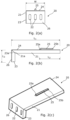
- Each of brackets 10, 20, 30, 40, 50 are substantially 'L-shaped' brackets comprising a first plate 14, 24, 34, 44, 54 and a second plate 16, 26, 36, 46, 56 wherein the second plate 16, 26, 36, 46, 56 extends substantially orthogonally from the first plate 14, 24, 34, 44, 54.
- one or more apertures 12, 22, 32, 42, 52 are provided in second plate 16, 26, 36, 46, 56.
- exemplary brackets 10, 20, 30, 40, 50 are secured to a substrate using appropriate fasteners which are secured to the substrate through one or more apertures 12, 22, 32, 42, 52 as will be disclosed more fully below.
- the apertures 12 of first exemplary bracket 10 comprise an elliptical or rounded oblong shape. This configuration of the apertures allows for adjustments during installation if so desired. It should be understood that the configuration of any one of the one or more apertures 12, 22, 32, 42, 52 in each of the exemplary brackets 10, 20, 30, 40, 50 can vary to accommodate various types of fasteners and/or substrates. For example, with reference to FIG.
- the one or more apertures 12 can be configured to comprise a central aperture 12a to allow for an appropriate fastener be used to secure the exemplary brackets of the present disclosure to a concrete or masonry substrate and one or more further apertures 12b, 12c surrounding the central aperture be configured to allow an appropriate fastener be used to secure the exemplary brackets of the present disclosure to a timber or metal (for example steel) substrate.
- Further exemplary configurations of apertures suitable for use are apertures 42, 52 shown in exemplary brackets 40 and 50 respectively. An installer can select the appropriate configuration of aperture(s) to use to secure the exemplary brackets 10, 20, 30, 40, 50 of the present disclosure to a substrate.
- First exemplary bracket 10 further comprises side walls 11, 13.
- Side walls 11 extend orthogonally from first plate 14 such that side walls 11 are spaced apart from each other by the width (W) of first exemplary bracket 10.
- side walls 13 extend orthogonally from second plate 16 such that side walls 13 are spaced apart from each other by the width (W) of first exemplary bracket 10.
- edges 11a and 13a of side walls 11 and 13 are configured to allow the side walls 11 and 13 seat together such that at least a portion of edges 11a and 13a are abutting edges.
- side walls 11 and 13 seat together such that at least a portion of side walls 11 and 13 overlap each other.
- Side walls 11 and 13 provide additional support to exemplary bracket 10 resisting or preventing rotational movement of bracket 10 when under load.
- the first plate 14 of first exemplary bracket 10 also comprises an optional clip mechanism 15.
- clip mechanism 15 comprises a connective form extension which comprises a first end 15a connected to first plate 15 and second end 15b remote from first end 15a and which is spaced apart from first plate 14 such that a gap is formed between clip mechanism 15 and first plate 14.
- clip mechanism 15 extends from first plate 14 in a direction opposite to that of second plate 16. Clip mechanism 15 is resiliently biased towards the first plate 14 and accommodates the main plate 62, 72, 82 of exemplary adaptor plates 60, 70 and 18 as illustrated in FIG. 9 and further disclosed below.
- clip mechanism 15 is configured to provide a resilient bias and can adopt any configuration known a person skilled in the art which will achieve this functionality.
- clip mechanism 15 is configured to have a 'duck bill profile' a profile that is recognised by a person skilled in the art to provide a resilient bias.
- first exemplary bracket 10 can comprise more than one clip mechanism if so desired.
- the width W of each of exemplary brackets 10, 20, 30, 40, 50 is variable and ranges between 50 to 200mm +/- 1.0mm.
- First exemplary bracket 10 comprises a width W that is approximately 80mm wide +/- 1.0mm.
- the length L 1 of the first plate 14, 24, 34, 44, 54 of exemplary brackets 10, 20, 30, 40, 50 14 is also variable and ranges between 40mm and 400mm +/- 1.0mm.
- Distance L 2 will be described with reference to first exemplary bracket 10 and is the distance between first end 15a and the end of first plate 14 remote from second plate 16. However, it should be understood that distance L 2 between the first end of the clip mechanism and the edge of the first plate remote from the second plate is dictated by the length L 4 of the adaptor plate as shown in FIG. 6(a) .
- distance L 2 of first exemplary bracket 10 is approximately 85mm +/- 1.0mm however this can be altered as required to accommodate the range of measurements provided for L 4 below.
- the length L 3 of second plate 16 is also variable and can range between approximately 50mm to 100mm +/- 1.0mm.
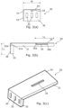
- Second exemplary bracket 20 as shown in FIG's 2(a) to 2(c) differs from that of first exemplary bracket 10 in that second exemplary bracket 20 has side walls 21, 23 on one side of bracket 20 only. As before, side walls 21 and 23 provide additional support to exemplary bracket 20 resisting or preventing rotational movement of bracket 20 when under load.
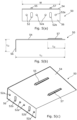
- Third exemplary bracket 30 as shown in Fig's 3(a) to 3(c) differs from that of the second exemplary bracket 20 in that the clip mechanism 35 of the third exemplary bracket 30 extends from first plate 35 in the same direction as that of second plate 36.
- Fourth exemplary bracket 40 as shown in FIG's 4(a) to 4(c) differs from that of first exemplary bracket 10 in that fourth exemplary bracket 40 has no side walls.
- Fourth exemplary bracket further comprises a detent 44a at the junction between the first plate 44 and the second plate 46 to prevent rotation of the first plate 44 relative to the second plate 46 when under load.
- the configuration of apertures 42 of fourth exemplary bracket comprises circular outer apertures 42a and an central oblong aperture 42b. It should be readily understood that apertures 42 could also be configured as described above with respect to the each of the first to third embodiments of exemplary brackets 10, 20 and 30.
- Fifth exemplary bracket 50 as shown in FIG's 5(a) to 5(c) is similar to that of fourth exemplary bracket 40, however in this exemplary embodiment the width W of fifth exemplary bracket 50 is approximately 150mm +/- 1.0mm wide.
- Fifth exemplary bracket further comprises a second clip mechanism 57 in first plate 54 and additional apertures in second plate 56. Second clip mechanism 57 is as described above in relation to clip mechanism 15 of first exemplary bracket 10. It should be understood that each of the differentiating features of the respective exemplary embodiments of brackets 10, 20, 30, 40, 50 are interchangeable and any one or more of those features can be used in any combination with each of the substantially 'L-shaped' exemplary brackets.
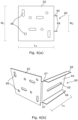
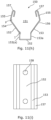
- Adaptor plates 60, 70 and 80 are substantially 'L-shaped' adaptor plates comprising main plate 62, 72, 82 and secondary plate 64, 74, 84 wherein the secondary plate 64, 74, 84 extends substantially orthogonally from the main plate 62, 72, 82.
- Main plate 62, 72, 82 further comprises a plurality of openings 66, 76, 86. In use, openings 66, 76, 86 allow the main plate 62, 72, 82 be secured to the first plate 14, 24, 34, 44, 54 of brackets 10, 20, 30, 40, 50 as will be described more fully below with respect to FIG. 9 .
- Secondary plate 64, 74, 84 of adaptor plates 60, 70 80 is further provided with one or more wing member(s) 68, 78, 88 which extend orthogonally from side edges 67, 87 of secondary plate 64, 74, 84 away from main plate 62, 72, 82.
- Secondary plate 64, 74, 84 of adaptor plates 60, 70,80 further comprises an optional elongate opening 65 as shown in FIG 6(b) .
- Elongate opening 65 provides an opening through which fasteners can be positioned to secure additional optional components such as for example internal and/or external corner trim fixing brackets 185 and 190 as shown in FIG's. 15 and 16 respectively to the concealed fastening system of the present disclosure as will be disclosed more fully below.
- main plate 62, 72, 82 is between approximately 46mm and 192mm +/- 1.0mm wide W 1 and between approximately 46mm and 192mm +/- 1.0mm long L 4 whilst secondary plate 64, 74, 84 is between approximately 33mm and 135mm +/- 1.0mm wide W 2 and between approximately 75mm and 180mm +/- 1.0mm long L 5 .
- width W 1 of the main plate 62, 72, 82 of the exemplary adaptor plate is approximately 4% to 8% less than the width W of the first plate 14, 24, 34, 44, 54 of the exemplary brackets 10, 20, 30, 40, 50.
- the main plate 62, 72, 82 of the adaptor plate 60, 70 80 and the first plate 14, 24, 34, 44, 54 of the bracket 10, 20, 30, 40, 50 prefferably has such an overlap between the main plate 62, 72, 82 of the adaptor plate 60, 70 80 and the first plate 14, 24, 34, 44, 54 of the bracket 10, 20, 30, 40, 50 to allow for load transfer and load distribution from the adaptor plate 60, 70, 80 across the width of the first plate 14, 24, 34, 44, 54 of the bracket 10, 20, 30, 40, 50.
- the width W 1 it is also possible for the width W 1 to be equal to or more than 8% less than the width W of the first plate 14, 24, 34, 44, 54 of the exemplary brackets 10, 20, 30, 40, 50.
- the width W 1 of the main plate 62, 72, 82 of the exemplary adaptor plate is approximately 4% to 75% less than the width W of the first plate 14, 24, 34, 44, 54 of the exemplary brackets 10, 20, 30, 40, 50.
- the width W 2 of secondary plate 64, 74, 84 is also variable and is dependent on the width of base element 102, 112 of rail 100, 110 as shown in FIG's. 10(a) and 10(b) and described more fully below.
- width W of first plate 14 of bracket 10 is approximately 80mm wide +/- 1.0mm
- width W 1 of main plate 62, 72, 82 is approximately 5% less than the width W of first plate or approximately 1475mm +/- 1.0mm wide.
- exemplary bracket 50 as shown in FIG. 5(a) to FIG. 5(c) , wherein width W of first plate 54 is approximately 150mm wide +/- 1.0mm, the width W 1 of the main plate 62, 72, 82 of exemplary adaptor plate 60, 70, 80 is approximately 5% less than the width W of exemplary bracket 50 or approximately 142.5mm +/- 1.0mm wide.
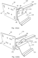
- Exemplary adaptor plates 60, 70 and 80 seat together with exemplary brackets 10, 20, 30, 40, 50 as shown in FIG. 9 .
- Main plate 82 of exemplary adaptor plate 80 is placed on exemplary bracket 30 and seated under clip mechanism 35.
- Clip mechanism 35 is resiliently biased towards the main plate 82 of exemplary adaptor plate 80 thereby holding exemplary adaptor plate 80 in position on exemplary bracket 30.
- additional fasteners are inserted through openings 86 to further secure exemplary adaptor plate 80 to exemplary bracket 30. It should be understood that in some instances clip mechanism 35 may not be present and in such embodiments, fasteners inserted through openings 86 will retain the adaptor plate 80 in position on exemplary bracket 30.
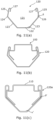
- Exemplary rails 100, 110 are substantially 'U' shaped articles comprising a base element 102, 112 from which side arms 104, 114, 106, 116 project orthogonally forming a recess 108, 118.
- side arms 104, 106 each comprise a first flange 103 wherein first flange 103 extends orthogonally from base element 102 such that side arms 104, 106 extend from base element 102 in the same direction but are spaced apart from each other.
- Side arms 104, 106 each further comprise a second flange 105 which extends orthogonally from first flange 103 remote from base element 102 in a direction away from base element 102 such that the second flange 105 extends in a plane parallel to but spaced apart from base element 102.
- the overall width W 3 of exemplary rail 100 is equivalent to the sum of the widths of the base element and each of the second flanges approximately, overall width W 3 ranges between approximately 40 mm and 150mm +/-1.0mm. In this exemplary embodiment overall width W 3 is approximately 48 mm +/- 1.0mm.
- the width of the base element 102 is such that the base element 102 can seat easily on either a substrate or the rear face of a cladding element or alternatively the secondary plate 64, 74, 84 of exemplary adaptor plates 60, 70, 80 when adaptor plates 60,70, 80 are present in the concealed fastening system of the present disclosure.
- the width of the base element 102 is variable. In the present embodiment as shown, the width of base element 102 approximately the same as W 2 i.e., is approximately 33mm +/- 1.0mm.
- Side arms 104, 106 each further comprise a third flange 107 which also extends in a direction away from base element 102 however third flange 107 extends orthogonally from second flange 105 in a plane parallel to but spaced apart from first flange 103.
- Side arms 104, 106 each further comprise fourth flange 109 which extends at an angle ⁇ from third flange 107 such that the fourth flanges 109 of each side arm 104, 106 extend towards each other forming an opening 109(a).
- Angle ⁇ in the exemplary rails of the present disclosure ranges between approximately 94° and 158°+/- 2° and more preferably is between approximately 125° and 145°+/- 2°.
- exemplary rails 100, 110 angle ⁇ is approximately 132° +/- 2°.
- the length of exemplary rails 100, 110 ranges between 25mm +/- 1.0mm and 20m +/- 1.0cm wherein the length of exemplary rail 100, 110 is the distance between opposing ends of the exemplary rail 100, 110 which is perpendicular to overall width W 3 .
- one or a plurality of rail elements can be used to mount a cladding element to a substrate.
- the concealed fastening system of the present disclosure could for example mount a cladding element that is 4.2m or 6m long using either an elongate rail that is approximately the same length as the cladding element or alternatively, using a plurality of discrete shorter rails that can be spaced apart along the same length as that of the cladding element as desired by the end user.
- exemplary rail 110 differs from that of FIG. 10(a) in that each of second flange 115 is provided with a nub 115a at the junction between second flange 115 and third flange 117.
- exemplary rail 110 can be provided with a groove or slot at the junction between second flange 115 and third flange 117.
- the groove or slot is provided in addition to nubs 115(a)
- the groove or slot is provided on second flange 115 between nubs 115(a) and first flange 113 to provide a seat for the end of hook 127 of receiver 120 as will be disclosed more fully below.
- Nubs 115(a) and/or grove or slot are provided in exemplary rail 110 to provide additional resistance to prevent the receiver from deflecting when in use as will be disclosed more fully below.
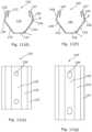
- First exemplary receiver 120 of the present disclosure is also a substantially 'U' shaped article with a complimentary configuration to that of the exemplary rail 100, 110. Further exemplary receivers are shown in each of FIG's 11(c) to 11(i) each of which have substantially the same 'U' shape configuration as that of first exemplary receiver 120.
- the configuration of each of the exemplary receivers 120, 120a, 130, 140, 150 allow the exemplary rails 100, 110 to seat within the cavity of each respective receiver 120, 120a, 130, 140, 150 as disclosed more fully below. Accordingly, exemplary receivers will be described generally in the following with reference to first exemplary receiver 120.
- First exemplary receiver 120 comprises a base section 122 from which side sections 124, 126 extend forming a central cavity 121 in the central internal area of the 'U' shaped article.
- the width of base section 122 is commensurate with base element 102 122 of exemplary rails 100, 110.
- Side sections 124, 126 each comprise a first projection 123 and a second projection 125, wherein first projections 123 extend at an angle ⁇ away from each side of base section 122 and second projections 125 extend at an angle ⁇ from the first projection 123 remote from base section 122.
- angle ⁇ between first projection 123 and second projection 125 is greater than angle ⁇ between first projection 123 and base section 122.
- Angle ⁇ in the exemplary receivers of the present disclosure ranges between approximately 93° and 157°+/- 2° and more preferably is between approximately 123° and 143°+/- 2°. In the exemplary receivers of the present disclosure ranges, angle ⁇ is approximately 131° +/- 2°.
- Angle ⁇ in the exemplary receivers of the present disclosure ranges between approximately 92° and 156° +/- 2° and more preferably is between approximately 120° and 140° +/- 2°. In the exemplary receivers of the present disclosure angle ⁇ in is approximately 125° +/- 2°. In the exemplary embodiments of the exemplary receivers 120, 120a, 130, 140, 150, angle ⁇ of exemplary rails 100, 110 is equal to or greater than angle ⁇ of the exemplary receivers 120, 120a, 130, 140, 150, of the present disclosure.
- each second projection 125 remote from first projection 123 is provided with a hook 127 in which the curved section is turned towards the central cavity 121.
- base section 122 is further provided with one or more holes to facilitate locating fasteners to allow the rail to be secured to the secondary plates 64, 74, 84 of adaptor plates 60, 70 ,80 or alternatively to the rear face 314 of a cladding panel 300 as shown in Fig 17(a) .
- Second exemplary receiver 120a as shown in FIG. 11(c) is similar to first exemplary receiver 120 however first projections 123 extend at an angle ⁇ ' away from each side of base section 122 and second projections 125 extend at an angle ⁇ ' from the first projection 123 remote from base section 122.
- each of side sections 124, 126 optionally further comprises one or more small projections or knurls.
- the one or more small projections are positioned on first projection 123 of side sections 124, 126.
- the one or more small projections reduce movement of the exemplary rails 100, 110 when seated within exemplary receivers 120, 120a, 130, 140, 150 (as further disclosed below) thus reducing noise created by such movement when in use.
- first and second exemplary embodiments of the concealed fastening system of the present disclosure in which rails 100 and 110 respectively are shown seated together with first and second exemplary receivers 120, 120a such that rails 100 and 110 seat within the central cavity 121, 121a of receivers 120, 120a whereby the second flange 105,115 of rails 100, 110 abut the hook 127, 127a of receivers 120, 120a.
- the ends of hook 127,127a which abut the second flange 105,115 of rails 100, 110, seat within a groove or slot provided on the outer surface of second flange 105, 115 to retain the ends of hook 127, 127a in position and provide restraint to prevent the receiver from deflecting when in use.
- first exemplary receiver 120 it should be understood that the disclosure is applicable to each of exemplary receivers 120, 120a, 130, 140, 150.
- First and second projections 123, 125 are configured to allow for limited pivotal movement at the junctions between the first projection 123 and the base section122; and the first projection 123 and second projection 125 respectively to allow side sections 124, 126 move apart for rails 100, 110 to be resiliently inserted into the central cavity 121. Once rails 100, 110 are inserted into the central cavity 121, side sections 124, 126 move back into position to allow engagement with the rail such that the hook 127 abuts second flange 105, 115 respectively thereby preventing movement of rails 100, 110 out of the central cavity 121.
- rails 110, 110 can be inserted into the central cavity 121 but cannot be easily removed without physical intervention to disengage and remove the impediments caused by hooks 127 and second sections 124, 126 respectively.
- the reference numerals of the various sections of the exemplary rails and receiver have largely been omitted from FIG's 11(b) and 11(c) for clarity.
- nubs 115a of exemplary rail 110 are configured to seat within the curved section of hook 127 thus providing additional resistance when in use.
- Any one of the exemplary rail receiver systems of the present disclosure can be adapted to include nubs in the configuration of the rail component.
- fasteners such as for example, one or more screws can be placed through the exemplary rail 100, 110 and exemplary receiver 120, 120a, 130, 140, 150 when seated together in the concealed fastening system of the present disclosure thereby preventing lateral movement of the exemplary rail 100, 110 and exemplary receiver 120, 120a, 130, 140, 150.
- the fasteners are restricted to one location on the concealed fastening system of the present disclosure to allow for natural movement within the concealed fastening system to occur but prevent disengagement of the exemplary rail 100, 110 from the exemplary receiver 120, 120a, 130, 140, 150.
- Third, fourth and fifth exemplary receivers 130, 140 and 150 of the present disclosure are shown in FIG's 11(d) to 11(i) respectively.
- Third exemplary receiver 130 as shown in FIG 11(d) and 11(e) is substantially identical to that of first exemplary receiver 120, base section 132 of second exemplary receiver 130 in which a plurality of hexagonal holes 138 provided to facilitate locating fasteners to secure exemplary rail 130 to the secondary plate 64, 74, 84 of adaptor plates 60, 70 ,80 or alternatively to the rear face 314 of a cladding panel 300 is shown.
- fourth exemplary receiver 140 as shown in FIG. 11(f) and 11(g) is substantially identical to that of first and third exemplary receiver 120 and 130.
- Fourth exemplary receiver comprises a plurality of oblong shaped holes 148 in base section 142. It should be understood that alternate configurations and frequencies of holes 138, 148 and 158 on base section 122, 132, 142, 152 can be selected as desired by the end user.
- angle ⁇ ranges between approximately 92° and 156° +/- 2°.
- angle ⁇ is more preferably between approximately 120° and 140° +/-2°.
- Angle ⁇ in the receiver of the present disclosure ranges between approximately 93° and 157°+/- 2° and more preferably is between approximately 123° and 143°+/- 2°.
- angle ⁇ is approximately 131° +/- 2°.
- fifth exemplary receiver 150 as shown in FIG's 11(h) and 11(i), there is shown an exemplary receiver which is similar to that of first, second, third and fourth exemplary receivers 120, 120a, 130 and 140.
- Fifth exemplary receiver 150 comprises extended side sections 154, 156 to allow for adjustment of the distance between a cladding panel 300 and a substrate relative to the first, second and third exemplary receivers 120, 130 and 140. In this way it is possible for the concealed fastening system of the present disclosure to achieve a lapped siding aesthetic as will be disclosed more fully below with reference to FIG. 19 .
- Fifth exemplary receiver 150 comprises a base section 152 from which extended side sections 154, 156 project forming central cavity 151 in the internal area of the substantially 'U' shaped article.
- Side sections 154, 166 each comprise an extension section 153a positioned between base section 152 and first projection 153.
- Each extension section 153a projects substantially orthogonally in the same direction from each side of base section 152 such that extension sections 153a are spaced apart and parallel to each other.
- Each of first projections 153 extend from extension sections 153a remote from base section 152 such that first projections 153 extend at an angle away from base section 152.
- first projections 153 and extension sections 153a corresponds to angle ⁇ of first, second and third exemplary receivers 120, 130 and 140 less the angle from which extension sections 153a extend from base section 152 which in the embodiment shown is substantially 90°. It should be understood that if first projections 153 were extended to base section 152, the angle between first projections 153 and base section 152 would be equivalent to angle ⁇ of first, second and third exemplary receivers 120, 130 and 140.
- second projections 155 extend at an angle ⁇ from the first projection 153 remote from base section 152.
- the end of each second projection 155 remote from first projection 153 is also provided with a hook 157 in which the curved section is turned towards the central cavity 151.
- Base section 152 is further provided with hexagonal shaped holes 158 to facilitate locating fasteners to allow the rail to be secured to the secondary plates 64, 74, 84 of adaptor plates 60, 70 80 or alternatively to the rear face 314 of a cladding panel 300 as shown in Fig 17(a) .
- exemplary receivers 120, 120a, 130, 140, 150, 500 are commensurate with the width and length of exemplary rails 100, 110.
- each of the exemplary rails 100, 110 and/or exemplary receivers 120, 120a, 130, 140, 150, 500 can be further provided with water management features to allow water to flow through the concealed fastening system of the present disclosure.
- Such features are known to a person skilled in the art and generally comprise a series of openings which allow water to pass through the exemplary rails 100, 110 and exemplary receivers 120, 120a, 130, 140, 150, 500 rather than sit on the top surface when in use, positioned between the substrate and cladding element.
- FIG. 12(a) and 12(b) there is shown perspective views of exemplary adaptor plate 60 on which receivers 120 and 150 have been secured to secondary plate 64 respectively.
- FIG. 12(a) shows adaptor plate 60 together with receiver 120 forming a central section 160 of a concealed fastening system of the present disclosure.
- FIG. 12(b) shows adaptor plate 60 together with receiver 150 forming an alternate embodiment of a central section 170 of a concealed fastening system of the present disclosure.
- Receiver 120, 150 receives rail 100, 110 as disclosed above.
- exemplary rails 100, 110 can be secured to secondary plate 64 in similar way such that the configuration of a central section is reversed whereby rails 100, 110 are secured to the adaptor plate 60 and exemplary receivers 120, 130, 140 and 150 are then inserted into exemplary rails 100, 110 as shown in FIG's 13(b) and 13(c) and as described more fully below.
- additional optional components such as for example internal and/or external corner trim fixing brackets 185 and 190 as shown in FIG's. 15 and 16 are secured to the base element 102, 112 of exemplary rails 100, 110 or base section 122, 122a, 132, 142, 152, 502 of exemplary receivers 120, 120a, 130, 140, 150, 500.
- additional optional components such as for example internal and/or external corner trim fixing brackets 185 and 190 are also secured to the secondary plate, 64, 74, 84 of exemplary adaptor plates 60, 70, 80 via elongate opening 65.
- FIG. 13(a) shows a third exemplary embodiment of the concealed fastening system 200 of the present disclosure comprising a first exemplary embodiment bracket 10 to which a first exemplary embodiment adaptor plate 60 has been secured as outlined above with respect to exemplary bracket 30 and exemplary adaptor plate 80 as shown in FIG. 9 .
- First exemplary receiver 120 has been secured to secondary plate 64 of adaptor plate 60 as outlined above with respect to FIG. 12(a) and exemplary rail 100 has been inserted into first exemplary receiver 120 as outlined above with respect to FIG. 11(b) .
- FIG. 13(b) shows a fourth exemplary embodiment of the concealed fastening system 210 of the present disclosure in which the locations of the exemplary rail 100 and first exemplary receiver 120 have been reversed, that is, exemplary rail 100 has been secured to secondary plate 64 of adaptor plate 60 and then inserted into first exemplary receiver 120.
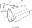
- FIG. 13(c) shows a fifth exemplary embodiment of the concealed fastening system 220 comprising a first exemplary embodiment bracket 10 and first exemplary embodiment adaptor plate 60 as before.
- Exemplary rail 100 has been secured to secondary plate 64 of adaptor plate 60 and then inserted into fourth exemplary receiver 150.
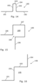
- FIG's 14, 15 and 16 there are shown an exemplary joint profile 180, an exemplary external corner profile 185 and an exemplary internal corner profile 190 respectively.
- Each of these profiles 180, 185 and 190 can be secured to the secured to the base element 102, 112 of exemplary rails 100, 110 or base section 122, 122a, 132, 142, 152, 502 of exemplary receivers 120, 120a, 130, 140, 150, 500 and also to the secondary plate 64, 74, 84 of adaptor plates 60, 70 80 via elongate opening 65 ( FIG 6(b) ) if adaptor plates 60, 70 80 are present.
- joint profiles such as joint profile 180 to provide a visible aesthetic joint between adjacent cladding elements.
- trim elements at the corners of buildings such as for example internal and external corner profiles 190 and 185 respectively to create the appropriate finish at a corner when installing cladding on a building structure.
- Joint profile 180 comprises fastening strips 181 on either side of protrusion 184 comprising side flanks 182 and base flank 183.
- joint profile 180 is secured to the secondary plate 64, 74 and 84 of one or more adaptor plates 60, 70 ,80 such that base flank 183 can be positioned between two adjacent cladding elements 300 ( FIG. 17(a) ) thereby forming the visible portion of a joint between the two adjacent cladding elements 300.
- internal corner profile 190 is secured to the secondary plate 64, 74, 84 of adaptor plates 60, 70 80 via side flanks 191, 194 such that internal flanks 192, 193 form an internal corner 195 between two cladding elements 300.
- external corner profile 185 is secured to the secondary plate 64, 74, 84 of adaptor plates 60, 70, 80 via side flanks 186 such that the box section 189 formed by internal flanks 187 forms an external corner between two cladding elements 300.
- Internal flanks 187 do not form a closed box section 189, a gap 188 is provided to allow some flexibility during the installation process and/or after installation.
- FIG. 17(a) is a perspective view of a building panel 300 comprising a front face 312, a rear face 314 spaced apart from the front face 312 and a side face 316 intermediate to and contiguous to each of the front face 312 and rear face 314.
- Building panel 300 is configured for installation on a building substructure such that major external surfaces or front face 312 of adjacent building panels 300 are positioned together in sequence as cladding panels 310 to create an external façade on the building.
- building panel 300 is a fibre cement cladding panel manufactured using the Hatschek process.
- Alternative suitable fibre cement manufacturing processes such as, for example, Flow-on or Fourdrinier or any other suitable manufacturing process known to the skilled person could also be used.
- building panel 300 can be made from any material suited to the intended application for example, timber, plasterboard, a panel which has alternate materials such as for example brick slips forming an external face of the panel or the like. Manufacturer's recommendations should be followed regarding suitability.
- a plurality of exemplary rails 100 are secured to the rear face 314 of cladding panel 300.
- exemplary rail 100 is installed using mechanical means or a combination of mechanical and chemical means.
- exemplary rails 100 secured to the rear face 314 of each building panel 300 is determined by the position of the corresponding exemplary receiver 120 on the substrate which will be determined in turn by the size and weight of building panels 300 to be secured to the substrate and also superimposed variable loading created by environmental conditions, for example wind loads which will be known and/or available to the person skilled in the art.
- one or more of exemplary rail 110 or alternatively in a reverse configuration one or more of exemplary receivers 120, 120a, 130, 140, 150 could be installed on the rear face 314 of cladding panel 300.
- exemplary rails 100, 110 are then installed directly or additionally with exemplary brackets 10, 20, 30, 40, 50 and adaptor plates 60, 70, 80 onto substrate 320.
- FIG. 17(b) is a partial perspective view of a building substrate 320 on which a number of horizontal and vertical framing members 324 and 326 respectively have been positioned on the external face 322 of building substrate 320.
- the position of the horizontal framing members 324 is such that the horizontal framing members 324 are aligned with the position of the exemplary rails 100 on the rear face 314 of building panel 300.
- the horizontal and vertical framing members 324 and 326 respectively are optional.
- horizontal and vertical framing members 324 and 326 respectively are often used to further assist when trying to overcome the instance where an external face 322 of a building substrate 322 has an uneven surface.
- Exemplary brackets 10 have been positioned on horizontal framing members 324.
- exemplary brackets 10 on horizontal framing members 324 is determined by a person skilled in the art and is determined by factors including the size and weight of building panels 300 to be secured to the substrate and also superimposed variable loading created by environmental conditions, for example wind loads. Any one of the exemplary brackets 10, 20, 30, 40, 50 of the present disclosure can be attached to the horizontal and vertical framing members 324 and 326 or directly to the building substrate 322 as desired by the installer.
- levelling of building sub-assemblies should be completed before installing any building panels for example, a floor top and base sub-assembly should be lined and levelled to the corners as determined necessary by the person skilled in the art. It is preferable that the preparatory works completed result in the substrate being weather protected before installation begins.
- building paper or house wrap may optionally also be installed on the external face 322 of the building substrate 322, between the external face 322 of the building substrate 322 and the horizontal and vertical framing members 324 and 326 (or exemplary brackets 10, 20, 30, 40, 50 of the present disclosure in the event that horizontal and vertical framing members 324 and 326 are not present).
- Building wrap is intended to provide additional protection against liquid water, such as from ingress of wind driven rain, through the external façade until it contacts a building frame where it may cause durability issues if it is resident there over extended periods of time.
- HardieWrap TM is a breathable non-woven polyolefin sheet, which prevents transmission of liquid water, but allows for transmission of water vapour, thereby allowing any water trapped against the frame to dry out over time.
- the building paper or building wrap is installed by nailing at predetermined intervals to the external face 322 of the building substrate 322, as per manufacturer's installation instructions.
- sheathing board as known to a person skilled in the art could be used to provide weather protection to the substrate.
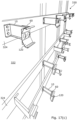
- FIG. 17(c) is a partial perspective side view 330 of the building substrate 320 of FIG. 17(b) which shows exemplary adaptor plate 60 and exemplary receiver 120 now secured to each of exemplary brackets 10 thereby forming a central section of a concealed fastening system of the present disclosure.
- the main plate of exemplary adaptor plate 60 is placed on the first plate of exemplary bracket 10.
- the main plate of exemplary adaptor plate 60 can also be placed and seated under a clip mechanism together with additional fasteners as desired to secure exemplary adaptor plate 60 to exemplary bracket 10.
- Exemplary receiver 120 has been secured to the secondary plate of adaptor plate 60 by fixings extending through holes in the base section of receiver 120.
- FIG. 17(d) is a partial perspective side view of the building substrate of FIG. 17(c) in which exemplary rail 100 positioned on the rear face 314 of building panels 300 has been placed in exemplary receiver 120.
- the building panel 300 is simply brought into alignment with the building substrate 320 and pushed into position so that the exemplary rail 100 is resiliently mounted within exemplary receiver 120 as disclosed above.
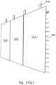
- FIG. 17(e) is a partial perspective front view of FIG. 17(d) showing building panels 300 installed using the concealed fastening system of the present disclosure.
- FIG. 18(a) to 18(d) shows an alternate embodiment of an exemplary receiver 500 in position on an adaptor plate (not visible) and bracket 10 mounted to horizontal member 324 on building substrate 320.
- Exemplary receiver 500 has been designed to accommodate a support member 510.
- Support member 510 comprises a square faced beam structure comprising at least a front face 514 and side face 512.
- Support member 510 is used to provide additional support at a junction between adjacent building panels 300. Additional support member 510 can also be used to provide an aesthetic finish as disclosed further below.
- Exemplary receiver 500 is similar to that of first, second, third and fourth exemplary receivers 120, 120a, 130 and 140 comprising a base section 502 from which a first projection 503 and a second projection 505, wherein first projections 503 extend from each side of base section 502 and second projections 505 extend from the first projection 503 remote from base section 502.
- the end of each second projection 505 remote from first projection 505 is provided with a hook 507.
- First projection 503, second projection 505 and hook 507 have a central cut-away portion 503a, 507c forming a seating area for support member 510 as shown in FIG's 18(b) and 18(c).
- Cut-away portion 507c forms a first and second region 507a and 507b within second projection 505 and hook 507 which enables an installer to insert an exemplary rail of the present disclosure into exemplary receiver 500 such that the exemplary rail and panel can abut each side face 512 and front face 512 as shown in FIG. 18(c) , therein exemplary rail 100 positioned on the rear face of panel 300 has been inserted into second region 507b.
- FIG. 18(d) there is shown a joint aesthetic which is created using the exemplary receiver 500 (shown in dotted form to the rear of two adjacent panels).
- Rear face 314 of panel 300 is seated against the front face 514 of support member 510 such that side face 316 of panel 300 is slightly off centre and perpendicular to front face 514 of support member 510.
- the second panel is also positioned slightly off centre on the support member 510 such that a gap is formed between the first and second panel forming a joint aesthetic wherein the front face 514 of support member 510 forms the base of the joint aesthetic and the side faces 316 of the first and second panels 300 form the sides of the joint aesthetic as shown in FIG. 18(d) .
- One or more exemplary receivers 500 can be used to support the panels as needed along the length of the joint aesthetic as determined by the installer.
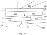
- FIG. 19 there is shown a further configuration 600 of two adjacent building panels 300 installed on a substrate using the concealed fastening system of the present disclosure such that the adjacent building panels 300 are installed in an overlapped configuration 600.
- Exemplary receivers 120 and 150 have both been secured to the rear face 314 of a panel 300 such that exemplary receiver 120 is located at the edge of rear face 314 adjacent first side face 316a and exemplary receiver 150 is secured slightly away from the edge of rear face 314 such that there is a space between exemplary receiver 150 and second side face 316b.
- receiver 150 is secured approximately 50mm +/- 0.5mm away from the edge of rear face 314.
- exemplary receiver 150 may be located at the edge of rear face 314 adjacent second side face 316b.
- the extended side sections 154, 156 of exemplary receiver 150 causes one side of panel 300 to project further than the opposing side of panel 300 to which exemplary receiver 120 is secured.
- the distance that exemplary receiver 150 projects further is equivalent to the approximate thickness of the building panel 300 such that the edge of one building panel 300 to which exemplary receiver 120 is secured can seat behind the edge of a second building panel 300 to which exemplary receiver 150 is secured forming an overlap is touching in the form of a shiplap joint as shown.
- exemplary receivers 120, 150 on first and second building panels 300 are collocated on exemplary rail 100 and first side face 316a abuts exemplary receiver 150.
- the distance that exemplary receiver 150 projects is greater than the approximate thickness of the building panel 300 such that the edge of one building panel 300 to which exemplary receiver 150 is secured is spaced apart from the edge of a second building panel 300 to which exemplary receiver 120 is secured forming an open-space lap joint.
- Each of the components of the concealed fastening system of the present disclosure may be formed from a range of materials including, but not limited to, metals such as steel or aluminium, or polymeric materials such as fibre reinforced polymer composites. It is preferable when using metals such as steel that the steel grades have mechanical properties which are equivalent to or exceed the requirements specified in EN 10346 2015 as associated with structural steel grades DX51, S220 and S450.
- the materials are formed into the desired configuration using known forming techniques such as but not limited to, for example, punching, rolling, pressing, forging or extrusion.
- the dimensions of the exemplary rails may change in accordance with the strength of the material used to form the component part for example if higher grade steel is used, greater loads can be carried by the concealed fastening system of the present disclosure. Consequently, either the size and/or frequency and/or positioning of the components of the concealed fastening system on a substrate/cladding element can be adjusted accordingly as determined by a person skilled in the art.
- the terms 'approximately', 'about', 'generally' and 'substantially' as used herein represent a value, amount, or characteristic close to the stated value, amount or characteristic that still performs a desired function or achieves a desired result.
- the terms 'approximately', 'about', 'generally' and 'substantially' may refer to an amount that is within less than or equal to 10% of, within less than or equal to 5% of, within less than or equal to 1% of, within less than or equal to 0.1% of, and within less than or equal to 0.01% of the stated amount.
Landscapes
- Engineering & Computer Science (AREA)
- Architecture (AREA)
- Civil Engineering (AREA)
- Structural Engineering (AREA)
- Connection Of Plates (AREA)
Abstract
A concealed fastening system suitable for securing a cladding element (300) to a substrate (320) comprising a receiver (120, 120a, 130, 140,150) comprising a base section (122) and side sections (124, 126) extending from the base section such that a central cavity (121) is formed, each side section comprising a hook (127) remote from the base section; and a rail (100, 110) comprising a base element (102) and side arms (104, 106) extending from the base element. The rail seats within the central cavity of the receiver such that the side arms of the rail abut the hook of the receiver. In use, either the receiver or the rail attaches to a substrate and the other of the receiver or rail connects to a cladding element. The system optionally further comprises a bracket (10, 20, 30, 40, 50) to which an adaptor plate (60, 70, 80) is attached. In use, the bracket and adaptor plate are seated between the substrate and either of the receiver or rail.
Description
- The present disclosure generally relates to a fastening system suitable for use with cladding elements to form a building façade wherein the cladding elements are secured to a building surface or framework using the fastening system to form the building façade. In particular, the present disclosure relates to a concealed fastening system wherein the fastening system used to secure cladding elements to a building surface or framework is hidden from general view.
- The embodiments have been developed primarily for use as a concealed fastening system for fibre cement cladding elements and will be described hereinafter with reference to this application. However, it will be appreciated that the concealed fastening system is not limited to this particular field of use and that the embodiments can also be used with other building products including other types of cladding elements and/or other fibre cement building products. Additionally, the embodiments of the concealed fastening system described hereinafter are with respect to a cladding system installed as an exterior building façade. It should be readily understood that the concealed fastening system of the present disclosure is also not limited to this particular application and that the embodiments hereinafter disclosed can also be used in an interior application if so desired.
- Any discussion of the prior art throughout the specification should in no way be considered as an admission that such prior art is widely known of forms part of the common general knowledge in the field.
- Cladding systems are widely known in building construction. In systems where façade panels or cladding elements of various types of materials are fixed to a substrate it is often desired to use a concealed or hidden fastening system to secure the façade panels to avoid face fixing the façade panel to the substrate through the exterior face of the façade panel. Such concealed fastening systems usually comprise a horizontal and vertical supporting framework to which the façade panels are secured using a complicated clip system. Such systems are expensive and complex to install. Such systems also provide limited flexibility to allow for on-site adjustments if required during installation.
- The present disclosure relates generally to a fastening system for use with cladding elements and is suitable for securing a cladding element to a substrate.
- The embodiments have been developed primarily for use with fiber cement cladding panels, elements or articles and will be described hereinafter with reference to this application. However, it will be appreciated that the embodiments are not limited to this field of use and that the embodiments can be used to provide concealed fastening of any product in any suitable field of use known to the person skilled in the art.
- According to the present disclosure there is provided a concealed fastening system as set out in appended Claims 1 to 15.
- In one embodiment, the concealed fastening system comprises a receiver comprising a base section and side sections extending from the base section such that a central cavity is formed, each side section comprising a first projection and a second projection wherein the first projection extends at an angle α from base section and the second projection extends at an angle β from the first projection remote from the base section and wherein the second projection remote from the first projection comprises a hook, wherein the base section of the receiver is configured to mount to either a cladding element or a substrate; a rail comprising a base element and side arms extending from the base element, each side arm comprising a first flange extending orthogonally from base element, a second flange extending orthogonally from the first flange remote from the base element, a third flange extending orthogonally from the second flange remote from the first flange and a fourth flange extending at an angle δ from third flange remote from the second flange such that the fourth flanges of each side arm extend towards each other, wherein the rail seats within the central cavity of the receiver such that the second flange of the rail abuts the hook of the receiver, wherein the base element of the rail is configured to mount to either a cladding element or a substrate; and wherein angle δ of the rail is equal to or greater than angle β of the receiver.
- In one embodiment, angle δ is approximately 94° and 158°+/- 2°. In a further embodiment, angle δ is approximately 132° +/- 2°.
- In one embodiment, angle α is approximately 92° and 156° +/- 2°. In a further embodiment, angle α is approximately 125° +/- 2°.
- In one embodiment, β is approximately 93° and 157°+/- 2°. In a further embodiment, angle β is approximately 131° +/- 2°.
- In a further embodiment, when angle δ is approximately 132° +/- 2°, angle α is approximately 125° +/- 2 and angle β is approximately 131° +/- 2°.
- In one embodiment, the second flange of the rail further comprises a nub at the junction between the second flange and the third flange. In a further embodiment, the second flange of the rail further comprises a groove at the junction between the second flange and the third flange.
- In one embodiment, the side sections of the receiver further comprise extended side sections wherein extended side sections are positioned between the base section and the first projection of the receiver.
- In one embodiment, the second projection and hook of the receiver further comprise a central cut-away portion.
- In one embodiment, the concealed fastening system further comprises a bracket comprising a first plate and a second plate wherein the second plate extends orthogonally from the first plate and the second plate is configured to attach to the substrate; and an adaptor plate comprising a main plate and a secondary plate wherein the secondary plate extends orthogonally from the main plate and the first plate of the bracket and the main plate of the adaptor plate are configured to attach to the substrate.
- In one embodiment, the bracket further comprises a resiliently biased clip mechanism wherein the clip mechanism comprises a connective form extension comprising a first end connected to the first plate and second end remote from the first end wherein the second end is spaced apart from the first plate such that a gap is formed between the clip mechanism and the first plate.
- In one embodiment, the bracket further comprises side walls extending orthogonally from first plate and/or second plate such that side walls are spaced apart from each other by width (W) of the bracket.
- In one embodiment, the bracket further comprises a detent at the junction between the first plate and the second plate.
- For the purposes of this specification, the term 'comprise' shall have an inclusive meaning. Thus it is understood that it should be taken to mean an inclusion of not only the listed components it directly references, but also non specified components. Accordingly, the term 'comprise' is to be attributable with as broad an interpretation as possible and this rationale should also be used when the terms 'comprised' and/or 'comprising' are used.
- Further aspects or embodiments of the present disclosure will become apparent from the ensuing description which is given by way of example only.
- Certain embodiments of the present disclosure will now be described, by way of example only, with reference to the accompanying drawings. From figure to figure, the same or similar reference numerals are used to designate similar components of an illustrated embodiment.
-
FIG. 1(a) is a front view of a first exemplary bracket of the present disclosure; -
FIG. 1(b) is a side view of the exemplary bracket ofFIG. 1(a) ; -
FIG. 1(c) is a perspective view of the exemplary bracket ofFIG. 1(a) ; -
FIG. 2(a) is a front view of a second exemplary bracket of the present disclosure; -
FIG. 2(b) is a side view of the exemplary bracket ofFIG. 2(a) ; -
FIG. 2(c) is a perspective view of the exemplary bracket ofFIG. 2(a) ; -
FIG. 3(a) is a front view of a third exemplary bracket of the present disclosure; -
FIG. 3(b) is a side view of the exemplary bracket ofFIG. 3(a) ; -
FIG. 3(c) is a perspective view of the exemplary bracket ofFIG. 3(a) ; -
FIG. 4(a) is a front view of a fourth exemplary bracket of the present disclosure; -
FIG. 4(b) is a side view of the exemplary bracket ofFIG. 4(a) ; -
FIG. 4(c) is a perspective view of the exemplary bracket ofFIG. 4(a) ; -
FIG. 5(a) is a front view of a fifth exemplary bracket of the present disclosure; -
FIG. 5(b) is a side view of the exemplary bracket ofFIG. 5(a) ; -
FIG. 5(c) is a perspective view of the exemplary bracket ofFIG. 5(a) ; -
FIG. 6(a) is a back view of a first exemplary adaptor plate of the present disclosure; -
FIG. 6(b) is a perspective view of the first exemplary adaptor plate ofFIG. 6(a) ; -
FIG. 7 is a back view of a second exemplary adaptor plate of the present disclosure; -
FIG. 8 is a back view of a third exemplary adaptor plate of the present disclosure; -
FIG. 9 is a perspective view of the third exemplary adaptor plate ofFIG. 8 together with a sixth exemplary bracket of the present disclosure; -
FIG. 10(a) is an end view of a first exemplary rail of the present disclosure; -
FIG. 10(b) is an end view of a second exemplary rail of the present disclosure; -
FIG. 11(a) is an end view of a first exemplary receiver of the present disclosure; -
FIG. 11(b) is an end view of the first concealed fastening system of the present disclosure comprising first exemplary rail ofFIG. 10(a) together with the first exemplary receiver ofFIG. 11(a) ; -
FIG. 11(c) is an end view of a second concealed fastening system of the present disclosure comprising first exemplary rail ofFIG. 10(b) together with an alternate embodiment of the first exemplary receiver ofFIG. 11(a) ; -
FIG. 11(d) and FIG 11(e) are an end view and a top view respectively of a second exemplary receiver of the present disclosure; -
FIG. 11(f) and FIG 11(g) are an end view and a top view respectively of a third exemplary receiver of the present disclosure; -
FIG. 11(h) and FIG 11(i) are an end view and a top view respectively of a fourth exemplary receiver of the present disclosure; -
FIG. 12(a) is a perspective view of a first exemplary sub assembly of the present disclosure comprising the first exemplary adaptor plate ofFIG. 6(a) together with the first exemplary receiver ofFIG 11(a) ; -
FIG. 12(b) is a perspective view of a second exemplary sub assembly of the present disclosure the first exemplary adaptor plate ofFIG. 6(a) together with the first exemplary receiver ofFIG 11(h) ; -
FIG. 13(a) is a perspective view of a third exemplary concealed fastening system of the present disclosure; -
FIG. 13(b) is a perspective view of a fourth exemplary concealed fastening system of the present disclosure; -
FIG. 13(c) is a perspective view of a fifth exemplary concealed fastening system of the present disclosure; -
FIG. 14 is an end view of an exemplary joint profile of the present disclosure; -
FIG. 15 is an end view of an exemplary external corner profile of the present disclosure; -
FIG. 16 is an end view of an exemplary internal corner profile of the present disclosure; -
FIG. 17(a) is a perspective view of the rear face of panel with the first exemplary rail ofFIG. 10 attached; -
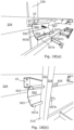
FIG 17(b) to FIG.17(e) are a series of perspective views of the installation process of the exemplary concealed fastening system of the present disclosure; -
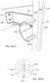
FIG 18(a) to FIG.18(d) are a series of perspective views of the installation process of an exemplary concealed fastening system of the present disclosure at a joint between adjacent panels; and -
FIG. 19 is a top perspective sectional view of a sixth exemplary concealed fastening system of the present disclosure. - In the description that follows, like parts may be marked throughout the specification and drawings with like reference numerals. The drawing figures are not necessarily to scale and certain features may be shown exaggerated in scale or in somewhat generalized or schematic form in the interest of clarity and conciseness. It should be understood that the measurements of provided for each of the features of the embodiments of the components of the concealed fastening system in the following disclosure are exemplary measurements for each of these features. The measurements of the embodiments can be adjusted as appropriate by a person skilled in the art in to scale the components to make larger or smaller components whilst achieving the functionality of the concealed fastening system.
- The concealed fastening system of the present disclosure is suitable for attaching or mounting one or more cladding elements to a substrate. With reference to FIG's 10(a), 11(a), 11(b) and 11(c), in one embodiment of the present disclosure, the concealed fastening system comprises a
receiver 120 comprising abase section 122 andside sections base section 122 such that acentral cavity 121 is formed, eachside section base section 122 terminates in ahook 127; and arail 100 comprising abase element 102 andside arms 104, 106 extending from thebase element 102. Therail 100 at least partially seats within thecentral cavity 121 of thereceiver 120 such that theside arms 104, 106 of the rail abut hooks 127 ofreceiver 120 and thebase section 122 of the receiver and thebase element 102 of the rail are spaced apart from each other by a distance as will be described more fully below. Thebase section 122 of the receiver and thebase element 102 of the rail are each configured to be secured to either of the substrate or the cladding elements such that the concealed fastening system of the present disclosure can be used whereby thereceiver 120 is attached to the substrate and therail 100 is attached to the cladding element or vice versa as desired by the end user and as disclosed more fully below. - In a further embodiment of the present disclosure, the concealed fastening system of the present disclosure further comprises a
bracket adaptor plate FIG. 9 . The addition ofbracket adaptor plate - All optional and essential components of the concealed fastening system of the present disclosure will now be described in more detail. For the purposes of the following the concealed fastening system will be disclosed with just the receiver and rail components and also with the bracket, adaptor plate, receiver and rail components.
- Each of the following components of the concealed fastening system of the present disclosure may be formed from a range of materials including, but not limited to, metals such as steel or aluminium, or polymeric materials such as fibre reinforced polymer composites. It is preferable when using metals such as steel that the steel grades have mechanical properties which are equivalent to or exceed the requirements specified in EN 10346 2015 as associated with structural steel grades DX51, S220 and S450.
- Referring now to
FIG. 1(a) to FIG. 5(c) there are shownexemplary brackets brackets first plate second plate second plate first plate exemplary brackets more apertures second plate exemplary brackets more apertures - Referring now specifically to FIG's 1(a) to 1(c), the
apertures 12 of firstexemplary bracket 10 comprise an elliptical or rounded oblong shape. This configuration of the apertures allows for adjustments during installation if so desired. It should be understood that the configuration of any one of the one ormore apertures exemplary brackets FIG. 1(c) the one ormore apertures 12 can be configured to comprise acentral aperture 12a to allow for an appropriate fastener be used to secure the exemplary brackets of the present disclosure to a concrete or masonry substrate and one or morefurther apertures apertures exemplary brackets exemplary brackets - First
exemplary bracket 10 further comprisesside walls Side walls 11 extend orthogonally fromfirst plate 14 such thatside walls 11 are spaced apart from each other by the width (W) of firstexemplary bracket 10. Similarly,side walls 13 extend orthogonally fromsecond plate 16 such thatside walls 13 are spaced apart from each other by the width (W) of firstexemplary bracket 10. Conveniently edges 11a and 13a ofside walls side walls edges embodiments side walls side walls Side walls exemplary bracket 10 resisting or preventing rotational movement ofbracket 10 when under load. - The
first plate 14 of firstexemplary bracket 10 also comprises anoptional clip mechanism 15. In the first exemplary embodiment of thebracket 10 shown,clip mechanism 15 comprises a connective form extension which comprises afirst end 15a connected tofirst plate 15 andsecond end 15b remote fromfirst end 15a and which is spaced apart fromfirst plate 14 such that a gap is formed betweenclip mechanism 15 andfirst plate 14. In the embodiment shown,clip mechanism 15 extends fromfirst plate 14 in a direction opposite to that ofsecond plate 16.Clip mechanism 15 is resiliently biased towards thefirst plate 14 and accommodates themain plate exemplary adaptor plates FIG. 9 and further disclosed below. It should be readily understood thatclip mechanism 15 is configured to provide a resilient bias and can adopt any configuration known a person skilled in the art which will achieve this functionality. For example, in an alternate exemplaryembodiment clip mechanism 15 is configured to have a 'duck bill profile' a profile that is recognised by a person skilled in the art to provide a resilient bias. It should also be understood that firstexemplary bracket 10 can comprise more than one clip mechanism if so desired. - The width W of each of
exemplary brackets exemplary bracket 10 comprises a width W that is approximately 80mm wide +/- 1.0mm. The length L1 of thefirst plate exemplary brackets exemplary bracket 10 and is the distance betweenfirst end 15a and the end offirst plate 14 remote fromsecond plate 16. However, it should be understood that distance L2 between the first end of the clip mechanism and the edge of the first plate remote from the second plate is dictated by the length L4 of the adaptor plate as shown inFIG. 6(a) . In the embodiment shown, distance L2 of firstexemplary bracket 10 is approximately 85mm +/- 1.0mm however this can be altered as required to accommodate the range of measurements provided for L4 below. The length L3 ofsecond plate 16 is also variable and can range between approximately 50mm to 100mm +/- 1.0mm. - Second
exemplary bracket 20 as shown in FIG's 2(a) to 2(c) differs from that of firstexemplary bracket 10 in that secondexemplary bracket 20 hasside walls bracket 20 only. As before,side walls exemplary bracket 20 resisting or preventing rotational movement ofbracket 20 when under load. - Third
exemplary bracket 30 as shown in Fig's 3(a) to 3(c) differs from that of the secondexemplary bracket 20 in that theclip mechanism 35 of the thirdexemplary bracket 30 extends fromfirst plate 35 in the same direction as that ofsecond plate 36. - Fourth
exemplary bracket 40 as shown in FIG's 4(a) to 4(c) differs from that of firstexemplary bracket 10 in that fourthexemplary bracket 40 has no side walls. Fourth exemplary bracket further comprises adetent 44a at the junction between thefirst plate 44 and thesecond plate 46 to prevent rotation of thefirst plate 44 relative to thesecond plate 46 when under load. Additionally, the configuration ofapertures 42 of fourth exemplary bracket comprises circularouter apertures 42a and an centraloblong aperture 42b. It should be readily understood thatapertures 42 could also be configured as described above with respect to the each of the first to third embodiments ofexemplary brackets - Fifth
exemplary bracket 50 as shown in FIG's 5(a) to 5(c) is similar to that of fourthexemplary bracket 40, however in this exemplary embodiment the width W of fifthexemplary bracket 50 is approximately 150mm +/- 1.0mm wide. Fifth exemplary bracket further comprises asecond clip mechanism 57 infirst plate 54 and additional apertures insecond plate 56.Second clip mechanism 57 is as described above in relation to clipmechanism 15 of firstexemplary bracket 10. It should be understood that each of the differentiating features of the respective exemplary embodiments ofbrackets - Referring now to
FIG. 6(a) to FIG. 8 there are shownexemplary adaptor plates Adaptor plates main plate secondary plate secondary plate main plate Main plate openings openings main plate first plate brackets FIG. 9 . -
Secondary plate adaptor plates secondary plate main plate Secondary plate adaptor plates elongate opening 65 as shown inFIG 6(b) .Elongate opening 65 provides an opening through which fasteners can be positioned to secure additional optional components such as for example internal and/or external cornertrim fixing brackets - In each of the exemplary embodiments of
adaptor plates main plate secondary plate main plate first plate exemplary brackets main plate adaptor plate first plate bracket main plate adaptor plate first plate bracket adaptor plate first plate bracket first plate exemplary brackets main plate first plate exemplary brackets secondary plate base element rail - With reference to the exemplary embodiments of the present disclosure and specifically with reference to the first
exemplary bracket 10 wherein width W offirst plate 14 ofbracket 10 is approximately 80mm wide +/- 1.0mm, width W1 ofmain plate exemplary bracket 50 as shown inFIG. 5(a) to FIG. 5(c) , wherein width W offirst plate 54 is approximately 150mm wide +/- 1.0mm, the width W1 of themain plate exemplary adaptor plate exemplary bracket 50 or approximately 142.5mm +/- 1.0mm wide. -
Exemplary adaptor plates exemplary brackets FIG. 9 .Main plate 82 ofexemplary adaptor plate 80 is placed onexemplary bracket 30 and seated underclip mechanism 35.Clip mechanism 35 is resiliently biased towards themain plate 82 ofexemplary adaptor plate 80 thereby holdingexemplary adaptor plate 80 in position onexemplary bracket 30. Although not shown, additional fasteners are inserted throughopenings 86 to further secureexemplary adaptor plate 80 toexemplary bracket 30. It should be understood that in some instances clipmechanism 35 may not be present and in such embodiments, fasteners inserted throughopenings 86 will retain theadaptor plate 80 in position onexemplary bracket 30. - Referring now to FIG's 10(a) and 10(b), there are shown two
exemplary rails Exemplary rails base element arms recess FIG. 10(a) ,side arms 104, 106 each comprise afirst flange 103 whereinfirst flange 103 extends orthogonally frombase element 102 such thatside arms 104, 106 extend frombase element 102 in the same direction but are spaced apart from each other.Side arms 104, 106 each further comprise asecond flange 105 which extends orthogonally fromfirst flange 103 remote frombase element 102 in a direction away frombase element 102 such that thesecond flange 105 extends in a plane parallel to but spaced apart frombase element 102. The overall width W3 ofexemplary rail 100 is equivalent to the sum of the widths of the base element and each of the second flanges approximately, overall width W3 ranges between approximately 40 mm and 150mm +/-1.0mm. In this exemplary embodiment overall width W3 is approximately 48 mm +/- 1.0mm. The width of thebase element 102 is such that thebase element 102 can seat easily on either a substrate or the rear face of a cladding element or alternatively thesecondary plate exemplary adaptor plates adaptor plates base element 102 is variable. In the present embodiment as shown, the width ofbase element 102 approximately the same as W2 i.e., is approximately 33mm +/- 1.0mm. -
Side arms 104, 106 each further comprise athird flange 107 which also extends in a direction away frombase element 102 howeverthird flange 107 extends orthogonally fromsecond flange 105 in a plane parallel to but spaced apart fromfirst flange 103.Side arms 104, 106 each further comprisefourth flange 109 which extends at an angle δ fromthird flange 107 such that thefourth flanges 109 of eachside arm 104, 106 extend towards each other forming an opening 109(a). Angle δ in the exemplary rails of the present disclosure ranges between approximately 94° and 158°+/- 2° and more preferably is between approximately 125° and 145°+/- 2°. In theexemplary rails exemplary rails exemplary rail exemplary rail exemplary rails - Referring now to
FIG 10(b) ,exemplary rail 110 differs from that ofFIG. 10(a) in that each ofsecond flange 115 is provided with a nub 115a at the junction betweensecond flange 115 andthird flange 117. Alternatively, or additionally,exemplary rail 110 can be provided with a groove or slot at the junction betweensecond flange 115 andthird flange 117. In the event that the groove or slot is provided in addition to nubs 115(a), the groove or slot is provided onsecond flange 115 between nubs 115(a) andfirst flange 113 to provide a seat for the end ofhook 127 ofreceiver 120 as will be disclosed more fully below. Nubs 115(a) and/or grove or slot are provided inexemplary rail 110 to provide additional resistance to prevent the receiver from deflecting when in use as will be disclosed more fully below. - Referring now to
FIG. 11(a) , there is shown a firstexemplary receiver 120 of the present disclosure. First exemplary receiver is also a substantially 'U' shaped article with a complimentary configuration to that of theexemplary rail exemplary receiver 120. The configuration of each of theexemplary receivers exemplary rails respective receiver exemplary receiver 120. - First
exemplary receiver 120 comprises abase section 122 from whichside sections central cavity 121 in the central internal area of the 'U' shaped article. The width ofbase section 122 is commensurate withbase element 102 122 ofexemplary rails -
Side sections first projection 123 and asecond projection 125, whereinfirst projections 123 extend at an angle α away from each side ofbase section 122 andsecond projections 125 extend at an angle β from thefirst projection 123 remote frombase section 122. In the exemplary embodiments, angle β betweenfirst projection 123 andsecond projection 125 is greater than angle α betweenfirst projection 123 andbase section 122. Angle β in the exemplary receivers of the present disclosure ranges between approximately 93° and 157°+/- 2° and more preferably is between approximately 123° and 143°+/- 2°. In the exemplary receivers of the present disclosure ranges, angle β is approximately 131° +/- 2°. Angle α in the exemplary receivers of the present disclosure ranges between approximately 92° and 156° +/- 2° and more preferably is between approximately 120° and 140° +/- 2°. In the exemplary receivers of the present disclosure angle α in is approximately 125° +/- 2°. In the exemplary embodiments of theexemplary receivers exemplary rails exemplary receivers - The end of each
second projection 125 remote fromfirst projection 123 is provided with ahook 127 in which the curved section is turned towards thecentral cavity 121. Although not visible inFIG. 11(a) ,base section 122 is further provided with one or more holes to facilitate locating fasteners to allow the rail to be secured to thesecondary plates adaptor plates rear face 314 of acladding panel 300 as shown inFig 17(a) . Secondexemplary receiver 120a as shown inFIG. 11(c) is similar to firstexemplary receiver 120 howeverfirst projections 123 extend at an angle α' away from each side ofbase section 122 andsecond projections 125 extend at an angle β' from thefirst projection 123 remote frombase section 122. - Although not shown, each of
side sections first projection 123 ofside sections exemplary rails exemplary receivers - Referring now specifically to FIG's 11(b) and 11(c), there is shown first and second exemplary embodiments of the concealed fastening system of the present disclosure in which rails 100 and 110 respectively are shown seated together with first and second
exemplary receivers rails central cavity 121, 121a ofreceivers rails hook 127, 127a ofreceivers rails second flange hook 127, 127a in position and provide restraint to prevent the receiver from deflecting when in use. The following will be described with reference to firstexemplary receiver 120 however it should be understood that the disclosure is applicable to each ofexemplary receivers second projections first projection 123 and the base section122; and thefirst projection 123 andsecond projection 125 respectively to allowside sections rails central cavity 121. Oncerails central cavity 121,side sections hook 127 abutssecond flange rails central cavity 121. Accordingly, rails 110, 110 can be inserted into thecentral cavity 121 but cannot be easily removed without physical intervention to disengage and remove the impediments caused byhooks 127 andsecond sections FIG. 11(c) nubs 115a ofexemplary rail 110 are configured to seat within the curved section ofhook 127 thus providing additional resistance when in use. Any one of the exemplary rail receiver systems of the present disclosure can be adapted to include nubs in the configuration of the rail component. In a further embodiment, fasteners such as for example, one or more screws can be placed through theexemplary rail exemplary receiver exemplary rail exemplary receiver exemplary rail exemplary receiver - Third, fourth and fifth
exemplary receivers exemplary receiver 130 as shown inFIG 11(d) and 11(e) is substantially identical to that of firstexemplary receiver 120,base section 132 of secondexemplary receiver 130 in which a plurality ofhexagonal holes 138 provided to facilitate locating fasteners to secureexemplary rail 130 to thesecondary plate adaptor plates rear face 314 of acladding panel 300 is shown. Similarly, fourthexemplary receiver 140 as shown inFIG. 11(f) and 11(g) is substantially identical to that of first and thirdexemplary receiver holes 148 inbase section 142. It should be understood that alternate configurations and frequencies ofholes base section - In each of first, second, third and fourth
exemplary receivers exemplary receivers exemplary receivers - Referring now specifically to fifth
exemplary receiver 150 as shown in FIG's 11(h) and 11(i), there is shown an exemplary receiver which is similar to that of first, second, third and fourthexemplary receivers exemplary receiver 150 comprises extendedside sections cladding panel 300 and a substrate relative to the first, second and thirdexemplary receivers FIG. 19 . Fifthexemplary receiver 150 comprises abase section 152 from whichextended side sections central cavity 151 in the internal area of the substantially 'U' shaped article.Side sections 154, 166 each comprise anextension section 153a positioned betweenbase section 152 andfirst projection 153. Eachextension section 153a projects substantially orthogonally in the same direction from each side ofbase section 152 such thatextension sections 153a are spaced apart and parallel to each other. Each offirst projections 153 extend fromextension sections 153a remote frombase section 152 such thatfirst projections 153 extend at an angle away frombase section 152. The angle γ between each offirst projections 153 andextension sections 153a, corresponds to angle α of first, second and thirdexemplary receivers extension sections 153a extend frombase section 152 which in the embodiment shown is substantially 90°. It should be understood that iffirst projections 153 were extended tobase section 152, the angle betweenfirst projections 153 andbase section 152 would be equivalent to angle α of first, second and thirdexemplary receivers second projections 155 extend at an angle β from thefirst projection 153 remote frombase section 152. The end of eachsecond projection 155 remote fromfirst projection 153 is also provided with ahook 157 in which the curved section is turned towards thecentral cavity 151.Base section 152 is further provided with hexagonal shapedholes 158 to facilitate locating fasteners to allow the rail to be secured to thesecondary plates adaptor plates rear face 314 of acladding panel 300 as shown inFig 17(a) . - It should also be understood that the width and length of
exemplary receivers exemplary rails - Although not shown, each of the
exemplary rails exemplary receivers exemplary rails exemplary receivers - Referring now to
FIG. 12(a) and 12(b) , there is shown perspective views ofexemplary adaptor plate 60 on whichreceivers secondary plate 64 respectively.FIG. 12(a) showsadaptor plate 60 together withreceiver 120 forming acentral section 160 of a concealed fastening system of the present disclosure.FIG. 12(b) showsadaptor plate 60 together withreceiver 150 forming an alternate embodiment of acentral section 170 of a concealed fastening system of the present disclosure.Receiver rail exemplary rails secondary plate 64 in similar way such that the configuration of a central section is reversed wherebyrails adaptor plate 60 andexemplary receivers exemplary rails - In one embodiment on the present disclosure additional optional components such as for example internal and/or external corner
trim fixing brackets base element exemplary rails base section exemplary receivers trim fixing brackets exemplary adaptor plates elongate opening 65. - Referring now to FIG's 13(a) 13(b) and 13(c), there is shown three further alternate exemplary embodiments of the
concealed fastening system FIG. 13(a) shows a third exemplary embodiment of theconcealed fastening system 200 of the present disclosure comprising a firstexemplary embodiment bracket 10 to which a first exemplaryembodiment adaptor plate 60 has been secured as outlined above with respect toexemplary bracket 30 andexemplary adaptor plate 80 as shown inFIG. 9 . Firstexemplary receiver 120 has been secured tosecondary plate 64 ofadaptor plate 60 as outlined above with respect toFIG. 12(a) andexemplary rail 100 has been inserted into firstexemplary receiver 120 as outlined above with respect toFIG. 11(b) .FIG. 13(b) shows a fourth exemplary embodiment of theconcealed fastening system 210 of the present disclosure in which the locations of theexemplary rail 100 and firstexemplary receiver 120 have been reversed, that is,exemplary rail 100 has been secured tosecondary plate 64 ofadaptor plate 60 and then inserted into firstexemplary receiver 120.FIG. 13(c) shows a fifth exemplary embodiment of theconcealed fastening system 220 comprising a firstexemplary embodiment bracket 10 and first exemplaryembodiment adaptor plate 60 as before.Exemplary rail 100 has been secured tosecondary plate 64 ofadaptor plate 60 and then inserted into fourthexemplary receiver 150. - Turning briefly to FIG's 14, 15 and 16, there are shown an exemplary
joint profile 180, an exemplaryexternal corner profile 185 and an exemplaryinternal corner profile 190 respectively. Each of theseprofiles base element exemplary rails base section exemplary receivers secondary plate adaptor plates FIG 6(b) ) ifadaptor plates joint profile 180 to provide a visible aesthetic joint between adjacent cladding elements. Similarly, it is also often desired to provide trim elements at the corners of buildings such as for example internal and external corner profiles 190 and 185 respectively to create the appropriate finish at a corner when installing cladding on a building structure. -
Joint profile 180, comprises fastening strips 181 on either side ofprotrusion 184 comprising side flanks 182 andbase flank 183. In use,joint profile 180 is secured to thesecondary plate more adaptor plates base flank 183 can be positioned between two adjacent cladding elements 300 (FIG. 17(a) ) thereby forming the visible portion of a joint between the twoadjacent cladding elements 300. Similarly, in the event it is desired to provide either internal or external corner profiles 190, 185 betweenadjacent cladding elements 300 on a building façade,internal corner profile 190 is secured to thesecondary plate adaptor plates internal flanks internal corner 195 between two claddingelements 300. In a similar manner,external corner profile 185 is secured to thesecondary plate adaptor plates box section 189 formed byinternal flanks 187 forms an external corner between two claddingelements 300. Internal flanks 187 do not form aclosed box section 189, agap 188 is provided to allow some flexibility during the installation process and/or after installation. - Turning now to FIG's 17(a) to 17(e), there is shown an exemplary sequence of steps for one method of installing a building panel using an exemplary concealed fastening system of the present disclosure;
FIG. 17(a) is a perspective view of abuilding panel 300 comprising afront face 312, arear face 314 spaced apart from thefront face 312 and aside face 316 intermediate to and contiguous to each of thefront face 312 andrear face 314. Buildingpanel 300 is configured for installation on a building substructure such that major external surfaces orfront face 312 ofadjacent building panels 300 are positioned together in sequence as claddingpanels 310 to create an external façade on the building. In the embodiment shown in the present disclosure,building panel 300 is a fibre cement cladding panel manufactured using the Hatschek process. Alternative suitable fibre cement manufacturing processes, such as, for example, Flow-on or Fourdrinier or any other suitable manufacturing process known to the skilled person could also be used. It is also understood that buildingpanel 300 can be made from any material suited to the intended application for example, timber, plasterboard, a panel which has alternate materials such as for example brick slips forming an external face of the panel or the like. Manufacturer's recommendations should be followed regarding suitability. A plurality ofexemplary rails 100 are secured to therear face 314 ofcladding panel 300. In one embodiment of the present disclosureexemplary rail 100 is installed using mechanical means or a combination of mechanical and chemical means. The number and position ofexemplary rails 100 secured to therear face 314 of eachbuilding panel 300 is determined by the position of the correspondingexemplary receiver 120 on the substrate which will be determined in turn by the size and weight ofbuilding panels 300 to be secured to the substrate and also superimposed variable loading created by environmental conditions, for example wind loads which will be known and/or available to the person skilled in the art. It is of course understood that in further embodiments of the present disclosure, one or more ofexemplary rail 110 or alternatively in a reverse configuration one or more ofexemplary receivers rear face 314 ofcladding panel 300. In such a reverse configurationexemplary rails exemplary brackets adaptor plates substrate 320. -
FIG. 17(b) is a partial perspective view of abuilding substrate 320 on which a number of horizontal and vertical framingmembers external face 322 ofbuilding substrate 320. The position of thehorizontal framing members 324 is such that thehorizontal framing members 324 are aligned with the position of theexemplary rails 100 on therear face 314 ofbuilding panel 300. It should be understood that the horizontal and vertical framingmembers members external face 322 of abuilding substrate 322 has an uneven surface.Exemplary brackets 10 have been positioned onhorizontal framing members 324. The frequency and position ofexemplary brackets 10 onhorizontal framing members 324 is determined by a person skilled in the art and is determined by factors including the size and weight ofbuilding panels 300 to be secured to the substrate and also superimposed variable loading created by environmental conditions, for example wind loads. Any one of theexemplary brackets members building substrate 322 as desired by the installer. - All preparatory works deemed necessary by a person skilled in the art for example, levelling of building sub-assemblies should be completed before installing any building panels for example, a floor top and base sub-assembly should be lined and levelled to the corners as determined necessary by the person skilled in the art. It is preferable that the preparatory works completed result in the substrate being weather protected before installation begins. Although not shown, building paper or house wrap, may optionally also be installed on the
external face 322 of thebuilding substrate 322, between theexternal face 322 of thebuilding substrate 322 and the horizontal and vertical framingmembers 324 and 326 (orexemplary brackets members external face 322 of thebuilding substrate 322, as per manufacturer's installation instructions. In alternative embodiments sheathing board as known to a person skilled in the art could be used to provide weather protection to the substrate. -
FIG. 17(c) is a partialperspective side view 330 of thebuilding substrate 320 ofFIG. 17(b) which showsexemplary adaptor plate 60 andexemplary receiver 120 now secured to each ofexemplary brackets 10 thereby forming a central section of a concealed fastening system of the present disclosure. As disclosed above, the main plate ofexemplary adaptor plate 60 is placed on the first plate ofexemplary bracket 10. Although not shown, it should be understood that the main plate ofexemplary adaptor plate 60 can also be placed and seated under a clip mechanism together with additional fasteners as desired to secureexemplary adaptor plate 60 toexemplary bracket 10.Exemplary receiver 120 has been secured to the secondary plate ofadaptor plate 60 by fixings extending through holes in the base section ofreceiver 120. -
FIG. 17(d) is a partial perspective side view of the building substrate ofFIG. 17(c) in whichexemplary rail 100 positioned on therear face 314 ofbuilding panels 300 has been placed inexemplary receiver 120. To achieve this, thebuilding panel 300 is simply brought into alignment with thebuilding substrate 320 and pushed into position so that theexemplary rail 100 is resiliently mounted withinexemplary receiver 120 as disclosed above. In this way a number ofbuilding panels 300 can be easily mounted on abuilding substrate 320 using the concealed fastening system of the present disclosure by simply pushing thebuilding panels 300 into position in accordance with the present disclosure.FIG. 17(e) is a partial perspective front view ofFIG. 17(d) showingbuilding panels 300 installed using the concealed fastening system of the present disclosure. -
FIG. 18(a) to 18(d) shows an alternate embodiment of anexemplary receiver 500 in position on an adaptor plate (not visible) andbracket 10 mounted tohorizontal member 324 onbuilding substrate 320.Exemplary receiver 500 has been designed to accommodate asupport member 510.Support member 510 comprises a square faced beam structure comprising at least afront face 514 andside face 512.Support member 510 is used to provide additional support at a junction betweenadjacent building panels 300.Additional support member 510 can also be used to provide an aesthetic finish as disclosed further below.Exemplary receiver 500 is similar to that of first, second, third and fourthexemplary receivers base section 502 from which afirst projection 503 and asecond projection 505, whereinfirst projections 503 extend from each side ofbase section 502 andsecond projections 505 extend from thefirst projection 503 remote frombase section 502. The end of eachsecond projection 505 remote fromfirst projection 505 is provided with ahook 507.First projection 503,second projection 505 and hook 507 have a central cut-away portion support member 510 as shown in FIG's 18(b) and 18(c). Cut-away portion 507c forms a first andsecond region second projection 505 and hook 507 which enables an installer to insert an exemplary rail of the present disclosure intoexemplary receiver 500 such that the exemplary rail and panel can abut eachside face 512 andfront face 512 as shown inFIG. 18(c) , thereinexemplary rail 100 positioned on the rear face ofpanel 300 has been inserted intosecond region 507b. With reference toFIG. 18(d) there is shown a joint aesthetic which is created using the exemplary receiver 500 (shown in dotted form to the rear of two adjacent panels). Rear face 314 ofpanel 300 is seated against thefront face 514 ofsupport member 510 such that side face 316 ofpanel 300 is slightly off centre and perpendicular tofront face 514 ofsupport member 510. In practice when a second panel is placed on the building substrate usingfirst region 507a, the second panel is also positioned slightly off centre on thesupport member 510 such that a gap is formed between the first and second panel forming a joint aesthetic wherein thefront face 514 ofsupport member 510 forms the base of the joint aesthetic and the side faces 316 of the first andsecond panels 300 form the sides of the joint aesthetic as shown inFIG. 18(d) . One or moreexemplary receivers 500 can be used to support the panels as needed along the length of the joint aesthetic as determined by the installer. - Turning now to
FIG. 19 there is shown afurther configuration 600 of twoadjacent building panels 300 installed on a substrate using the concealed fastening system of the present disclosure such that theadjacent building panels 300 are installed in an overlappedconfiguration 600.Exemplary receivers rear face 314 of apanel 300 such thatexemplary receiver 120 is located at the edge ofrear face 314 adjacentfirst side face 316a andexemplary receiver 150 is secured slightly away from the edge ofrear face 314 such that there is a space betweenexemplary receiver 150 andsecond side face 316b. In the exemplary embodiment shownreceiver 150 is secured approximately 50mm +/- 0.5mm away from the edge ofrear face 314. It should be understood that it is also possible forexemplary receiver 150 to be located at the edge ofrear face 314 adjacentsecond side face 316b. When afirst panel 300 is installed on a building substrate using the concealed fastening system of the present disclosure, theextended side sections exemplary receiver 150 causes one side ofpanel 300 to project further than the opposing side ofpanel 300 to whichexemplary receiver 120 is secured. The distance thatexemplary receiver 150 projects further is equivalent to the approximate thickness of thebuilding panel 300 such that the edge of onebuilding panel 300 to whichexemplary receiver 120 is secured can seat behind the edge of asecond building panel 300 to whichexemplary receiver 150 is secured forming an overlap is touching in the form of a shiplap joint as shown. In this configuration,exemplary receivers second building panels 300 are collocated onexemplary rail 100 andfirst side face 316a abutsexemplary receiver 150. In an alternate embodiment, the distance thatexemplary receiver 150 projects is greater than the approximate thickness of thebuilding panel 300 such that the edge of onebuilding panel 300 to whichexemplary receiver 150 is secured is spaced apart from the edge of asecond building panel 300 to whichexemplary receiver 120 is secured forming an open-space lap joint. - Each of the components of the concealed fastening system of the present disclosure may be formed from a range of materials including, but not limited to, metals such as steel or aluminium, or polymeric materials such as fibre reinforced polymer composites. It is preferable when using metals such as steel that the steel grades have mechanical properties which are equivalent to or exceed the requirements specified in EN 10346 2015 as associated with structural steel grades DX51, S220 and S450. In the instance where the components of the concealed fastening system are formed from metals such as steel or aluminium, the materials are formed into the desired configuration using known forming techniques such as but not limited to, for example, punching, rolling, pressing, forging or extrusion. It should also be understood that the dimensions of the exemplary rails may change in accordance with the strength of the material used to form the component part for example if higher grade steel is used, greater loads can be carried by the concealed fastening system of the present disclosure. Consequently, either the size and/or frequency and/or positioning of the components of the concealed fastening system on a substrate/cladding element can be adjusted accordingly as determined by a person skilled in the art.
- It will of course be understood that the invention is not limited to the specific details described herein, which are given by way of example only, and that various modifications and alterations are possible within the scope of the disclosure as defined in the appended claims.
- Certain features that are described in this disclosure in the context of separate implementations can also be implemented in combination in a single implementation. Conversely, various features that are described in the context of a single implementation can also be implemented in multiple implementations separately or in any suitable sub-combination. Moreover, although features may be described above as acting in certain combinations, one or more features from a claimed combination can, in some cases, be excised from the combination, and the combination may be claimed as any sub-combination or variation of any sub-combination.
- Moreover, while methods may be depicted in the drawings or described in the specification in a particular order, such methods need not be performed in the particular order shown or in sequential order, and that all methods need not be performed, to achieve desirable results. Other methods that are not depicted or described can be incorporated in the example methods and processes. For example, one or more additional methods can be performed before, after, simultaneously, or between any of the described methods. Further, the methods may be rearranged or reordered in other implementations. Also, the separation of various system components in the implementations described above should not be understood as requiring such separation in all implementations, and it should be understood that the described components and systems can generally be integrated together in a single product or packaged into multiple products. Additionally, other implementations are within the scope of this disclosure.
- Conditional language, such as 'can', 'could', 'might', or 'may', unless specifically stated otherwise, or otherwise understood within the context as used, is generally intended to convey that certain embodiments include or do not include, certain features, elements, and/or steps. Thus, such conditional language is not generally intended to imply that features, elements, and/or steps are in any way required for one or more embodiments.
- Conjunctive language, such as the phrase 'at least one of X, Y, and Z' unless specifically stated otherwise, is otherwise understood with the context as used in general to convey that an item, term, etc. may be either X, Y or Z. Thus, such conjunctive language is not generally intended to imply that certain embodiments require the presence of at least one of X, at least one of Y, and at least one of Z.
- Language of degree used herein, such as the terms 'approximately', 'about', 'generally' and 'substantially' as used herein represent a value, amount, or characteristic close to the stated value, amount or characteristic that still performs a desired function or achieves a desired result. For example, the terms 'approximately', 'about', 'generally' and 'substantially' may refer to an amount that is within less than or equal to 10% of, within less than or equal to 5% of, within less than or equal to 1% of, within less than or equal to 0.1% of, and within less than or equal to 0.01% of the stated amount.
- Although making and using various embodiments are discussed in detail below, it should be appreciated that the description provides many inventive concepts that may be embodied in a wide variety of contexts. The specific aspects and embodiments discussed herein are merely illustrative of ways to make and use the systems and methods disclosed herein and do not limit the scope of the disclosure. The systems and methods described herein may be used in conjunction with decorated fibre cement building panels and are described herein with reference to this application. However, it will be appreciated that the disclosure is not limited to this particular field of use.
- Some embodiments have been described in connection with the accompanying drawings. The figures are not drawn to scale, and some features have been exaggerated for the purposes of clarity an conciseness. Dimensions and proportions other than what are shown are contemplated and are within the scope of the disclosed inventions. Distances, angles, etc. are merely illustrative and do not necessarily bear an exact relationship to actual dimensions and layout of the devices illustrated. Components can be added, removed, and/or rearranged. Further, the disclosure herein of any particular feature, aspect, method, property, characteristic, quality, attribute, element, or the like in connection with various embodiments can be used in all other embodiments set forth herein. Additionally, it will be recognized that any methods described herein may be practised using any device suitable for performing the recited steps.
- While a number of embodiments and variations thereof have been described in detail, other modifications and methods of using the same will be apparent to those of skill in the art. Accordingly, it should be understood that various applications, modifications, materials, and substitutions can be made of equivalents without departing from the unique and inventive disclosure herein or the scope of the claims.
Claims (15)
- A concealed fastening system suitable for securing a cladding element to a substrate comprising;a receiver (120, 120a, 130, 140, 150) comprising a base section (122) and side sections (124, 126) extending from the base section such that a central cavity (121) is formed, each side section comprising a first projection (123) and a second projection (125) wherein the first projection extends at an angle α from base section and the second projection extends at an angle β from the first projection remote from the base section and wherein the second projection remote from the first projection comprises a hook (127), wherein the base section of the receiver is configured to mount to either a cladding element (300) or a substrate (320);a rail (100, 110) comprising a base element (102) and side arms (104, 106) extending from the base element, each side arm comprising a first flange (103) extending orthogonally from base element, a second flange (105) extending orthogonally from the first flange remote from the base element, a third flange (107) extending orthogonally from the second flange remote from the first flange and a fourth flange (109) extending at an angle δ from third flange remote from the second flange such that the fourth flanges of each side arm extend towards each other, wherein the rail seats within the central cavity of the receiver such that the second flange (105) of the rail abuts the hook (127) of the receiver, wherein the base element of the rail is configured to mount to either a cladding element (300) or a substrate (320); and wherein angle δ of the rail is equal to or greater than angle β of the receiver.
- A concealed fastening system as claimed in Claim 1, wherein the angle δ is approximately 94° and 158°+/- 2.
- A concealed fastening system as claimed Claim 1 or Claim 2, wherein the angle δ is approximately 132° +/- 2°.
- A concealed fastening system as claimed in any one of the previous claims, wherein the angle α is approximately 92° and 156° +/- 2°.
- A concealed fastening system as claimed in any one of the previous claims, wherein the angle α is approximately 125° +/- 2°.
- A concealed fastening system as claimed in any one of the previous claims, wherein the angle β is approximately 93° and 157°+/- 2°.
- A concealed fastening system as claimed in any one of the previous claims, wherein the angle β is approximately 131° +/- 2°.
- A concealed fastening system as claimed in any one of the previous claims, wherein the second flange of the rail further comprises a nub (115(a)) at the junction between the second flange and the third flange.
- A concealed fastening system as claimed in any one of the previous claims, wherein the second flange of the rail further comprises a groove at the junction between the second flange and the third flange.
- A concealed fastening system as claimed in any one of the previous claims, wherein the side sections of the receiver further comprise extended side sections (153a) wherein extended side sections are positioned between the base section and the first projection of the receiver.
- A concealed fastening system as claimed in any one of the previous claims, wherein the second projection and hook of the receiver further comprise a central cut-away portion (507c).
- A concealed fastening system as claimed in any one of the previous claims, further comprising a bracket (10, 20, 30, 40, 50) comprising a first plate (14) and a second plate (16) wherein the second plate extends orthogonally from the first plate and the second plate is configured to attach to the substrate; and an adaptor plate (60, 70, 80) comprising a main plate (62) and a secondary plate (64) wherein the secondary plate extends orthogonally from the main plate and the first plate of the bracket and the main plate of the adaptor plate are configured to attach to the substrate.
- A concealed fastening system as claimed in any one of the preceding claims, wherein the bracket further comprises a clip mechanism (15) wherein the clip mechanism comprises a connective form extension comprising a first end (15a) connected to the first plate and second end (15b) remote from the first end wherein the second end is spaced apart from the first plate such that a gap is formed between the clip mechanism and the first plate.
- A concealed fastening system as claimed in any one of the preceding claims, wherein the bracket further comprises side walls (11, 13) extending orthogonally from first plate and/or second plate such that side walls are spaced apart from each other by width (W) of the bracket.
- A concealed fastening system as claimed in any one of the preceding claims, wherein the bracket further comprises a detent (44a) at the junction between the first plate and the second plate.
Priority Applications (4)
| Application Number | Priority Date | Filing Date | Title |
|---|---|---|---|
| EP23151501.6A EP4400670A1 (en) | 2023-01-13 | 2023-01-13 | A fastening system |
| AU2023285745A AU2023285745A1 (en) | 2023-01-13 | 2023-12-19 | A fastening system |
| CA3223813A CA3223813A1 (en) | 2023-01-13 | 2023-12-19 | A fastening system |
| US18/404,716 US12703982B2 (en) | 2023-01-13 | 2024-01-04 | Fastening system |
Applications Claiming Priority (1)
| Application Number | Priority Date | Filing Date | Title |
|---|---|---|---|
| EP23151501.6A EP4400670A1 (en) | 2023-01-13 | 2023-01-13 | A fastening system |
Publications (1)
| Publication Number | Publication Date |
|---|---|
| EP4400670A1 true EP4400670A1 (en) | 2024-07-17 |
Family
ID=84981290
Family Applications (1)
| Application Number | Title | Priority Date | Filing Date |
|---|---|---|---|
| EP23151501.6A Pending EP4400670A1 (en) | 2023-01-13 | 2023-01-13 | A fastening system |
Country Status (4)
| Country | Link |
|---|---|
| US (1) | US12703982B2 (en) |
| EP (1) | EP4400670A1 (en) |
| AU (1) | AU2023285745A1 (en) |
| CA (1) | CA3223813A1 (en) |
Citations (5)
| Publication number | Priority date | Publication date | Assignee | Title |
|---|---|---|---|---|
| US3815309A (en) * | 1972-10-02 | 1974-06-11 | Specialties Const | Fastening system |
| DE9000858U1 (en) * | 1990-01-26 | 1990-04-05 | Wagner, Peter, Dipl.-Ing., 3303 Vechelde | Fastening element for facade elements, especially bricks |
| WO2001038667A1 (en) * | 1999-11-22 | 2001-05-31 | Ralph Essebier | Wainscot/panel fixing system for a wall and a ceiling |
| KR200235678Y1 (en) * | 2001-03-14 | 2001-10-08 | 덕 수 강 | A device fixing the stone |
| WO2017042521A1 (en) * | 2015-09-11 | 2017-03-16 | Stiplastics | Device for keeping a facing element at a spacing from a vapor barrier membrane, and dual-reinforcement construction system including such a device |
Family Cites Families (18)
| Publication number | Priority date | Publication date | Assignee | Title |
|---|---|---|---|---|
| US3144733A (en) * | 1961-12-26 | 1964-08-18 | United States Gypsum Co | Clip construction |
| US4408427A (en) * | 1980-10-03 | 1983-10-11 | Donn Incorporated | Framing system for demountable walls or the like |
| FR2522049A1 (en) * | 1982-02-25 | 1983-08-26 | Guerin Gabriel | DEVICE FOR FASTENING A STONE PLATE COATING RECONSTITUTED ON A WALL STRUCTURE |
| US5590502A (en) * | 1995-02-28 | 1997-01-07 | Usg Interiors, Inc. | Panel access clip for relocatable partitions |
| DE19908585A1 (en) * | 1999-02-27 | 2000-08-31 | Profil Vertrieb Gmbh | Profile that can be attached to an anchoring base |
| JP4700455B2 (en) * | 2005-09-21 | 2011-06-15 | ニチハ株式会社 | Fastening bracket and outer wall construction structure |
| US8882065B2 (en) * | 2011-04-26 | 2014-11-11 | Kimball International, Inc. | Two piece track assembly |
| DE102013200211A1 (en) * | 2013-01-09 | 2014-07-10 | Hilti Aktiengesellschaft | console |
| US20140196399A1 (en) * | 2013-01-14 | 2014-07-17 | II John David Egri | Expansion Bracket |
| US9206609B2 (en) * | 2013-05-02 | 2015-12-08 | Donald George White | Thermal break wall systems and thermal adjustable clip |
| US10145122B2 (en) * | 2014-04-01 | 2018-12-04 | Control Y Desarrollo Empresarial, S.L. | Surface coating and clamp for said coating |
| CN105696754A (en) * | 2014-12-10 | 2016-06-22 | 顺和系统有限公司 | Modular decorative wall panel |
| ES2586736B1 (en) * | 2015-04-15 | 2017-09-07 | Cupa Innovacion S.L.U. | VENTILATED FACADE |
| US9834941B1 (en) * | 2016-02-18 | 2017-12-05 | Henry H. Bilge | Thermal break system for wall panels secured to an existing wall |
| GB2593050B (en) * | 2021-02-23 | 2022-03-09 | Metalline Services Ltd | A multipart bracket and rainscreen cladding mount system including same |
| ES1286749Y (en) * | 2021-11-18 | 2022-05-09 | Sist Tecnicos Del Accesorio Y Componentes S L | DEVICE FOR FIXING VENTILATED FAÇADES |
| US20240360677A1 (en) * | 2023-04-28 | 2024-10-31 | ECO Cladding | Façade cladding system and bracket therefor |
| US20250347121A1 (en) * | 2024-01-25 | 2025-11-13 | SFS Group International AG | Facade panel fastening system |
-
2023
- 2023-01-13 EP EP23151501.6A patent/EP4400670A1/en active Pending
- 2023-12-19 CA CA3223813A patent/CA3223813A1/en active Pending
- 2023-12-19 AU AU2023285745A patent/AU2023285745A1/en active Pending
-
2024
- 2024-01-04 US US18/404,716 patent/US12703982B2/en active Active
Patent Citations (5)
| Publication number | Priority date | Publication date | Assignee | Title |
|---|---|---|---|---|
| US3815309A (en) * | 1972-10-02 | 1974-06-11 | Specialties Const | Fastening system |
| DE9000858U1 (en) * | 1990-01-26 | 1990-04-05 | Wagner, Peter, Dipl.-Ing., 3303 Vechelde | Fastening element for facade elements, especially bricks |
| WO2001038667A1 (en) * | 1999-11-22 | 2001-05-31 | Ralph Essebier | Wainscot/panel fixing system for a wall and a ceiling |
| KR200235678Y1 (en) * | 2001-03-14 | 2001-10-08 | 덕 수 강 | A device fixing the stone |
| WO2017042521A1 (en) * | 2015-09-11 | 2017-03-16 | Stiplastics | Device for keeping a facing element at a spacing from a vapor barrier membrane, and dual-reinforcement construction system including such a device |
Also Published As
| Publication number | Publication date |
|---|---|
| US20240240466A1 (en) | 2024-07-18 |
| AU2023285745A1 (en) | 2024-08-01 |
| US12703982B2 (en) | 2026-08-11 |
| CA3223813A1 (en) | 2025-07-02 |
Similar Documents
| Publication | Publication Date | Title |
|---|---|---|
| US10876299B2 (en) | Fastening system | |
| WO2008101320A1 (en) | Apparatus and method for installing cladding to structures | |
| WO2016028500A1 (en) | Suspended ceiling grid system | |
| WO2014071450A1 (en) | A cladding assembly | |
| AU2019283988A1 (en) | Multifunctional flashing device | |
| EP1757751A1 (en) | Wall face exterior structure of outer wall face insulation building and its wall face exterior furring, lateral furring strip frame for installing wall face exterior material and wall face exterior froming method by lateral furring strip frame, and exterior furring material and outer wall employing | |
| EP3631117B1 (en) | A system for fixing panels on the facades of the buildings | |
| RU2771308C2 (en) | Suspension system | |
| US7047702B1 (en) | Perimeter angle trim | |
| US20240240466A1 (en) | Fastening system | |
| US20210164234A1 (en) | Clip for cast stone wall system | |
| EP1764455A2 (en) | Anchoring system for cladding panels and profiles, particularly for ventilated facades | |
| US20230183985A1 (en) | Building surface product including attachment structures, building surface system, and method of assembly | |
| US20240060310A1 (en) | A multipart bracket and rainscreen cladding mount system including same | |
| CZ2001800A3 (en) | Connecting profile for ceiling tiles | |
| US20230392384A1 (en) | Cladding installation system | |
| US20250172038A1 (en) | Architectural Panel Mounting Systems and Methods | |
| JP7777791B2 (en) | Panel Device | |
| EP3978699B1 (en) | Demountable wall partition system | |
| JP2019116785A (en) | Ceiling panel | |
| AU2023263540A1 (en) | Façade system | |
| WO2023087111A1 (en) | Clip and wall facing system for segmental retaining walls | |
| AU745364B2 (en) | Linear diffuser mounting frame | |
| US20060216109A1 (en) | Attachment device for building materials | |
| IE20230197A1 (en) | A Cladding installation system |
Legal Events
| Date | Code | Title | Description |
|---|---|---|---|
| PUAI | Public reference made under article 153(3) epc to a published international application that has entered the european phase |
Free format text: ORIGINAL CODE: 0009012 |
|
| STAA | Information on the status of an ep patent application or granted ep patent |
Free format text: STATUS: THE APPLICATION HAS BEEN PUBLISHED |
|
| AK | Designated contracting states |
Kind code of ref document: A1 Designated state(s): AL AT BE BG CH CY CZ DE DK EE ES FI FR GB GR HR HU IE IS IT LI LT LU LV MC ME MK MT NL NO PL PT RO RS SE SI SK SM TR |
|
| STAA | Information on the status of an ep patent application or granted ep patent |
Free format text: STATUS: REQUEST FOR EXAMINATION WAS MADE |
|
| 17P | Request for examination filed |
Effective date: 20241218 |