EP4400645A1 - Method for providing a conductive polymer material on fabric - Google Patents
Method for providing a conductive polymer material on fabric Download PDFInfo
- Publication number
- EP4400645A1 EP4400645A1 EP23151775.6A EP23151775A EP4400645A1 EP 4400645 A1 EP4400645 A1 EP 4400645A1 EP 23151775 A EP23151775 A EP 23151775A EP 4400645 A1 EP4400645 A1 EP 4400645A1
- Authority
- EP
- European Patent Office
- Prior art keywords
- fabric
- oxidant
- stencil
- conductive polymer
- polymer material
- Prior art date
- Legal status (The legal status is an assumption and is not a legal conclusion. Google has not performed a legal analysis and makes no representation as to the accuracy of the status listed.)
- Withdrawn
Links
Images



Classifications
-
- D—TEXTILES; PAPER
- D06—TREATMENT OF TEXTILES OR THE LIKE; LAUNDERING; FLEXIBLE MATERIALS NOT OTHERWISE PROVIDED FOR
- D06M—TREATMENT, NOT PROVIDED FOR ELSEWHERE IN CLASS D06, OF FIBRES, THREADS, YARNS, FABRICS, FEATHERS OR FIBROUS GOODS MADE FROM SUCH MATERIALS
- D06M11/00—Treating fibres, threads, yarns, fabrics or fibrous goods made from such materials, with inorganic substances or complexes thereof; Such treatment combined with mechanical treatment, e.g. mercerising
- D06M11/07—Treating fibres, threads, yarns, fabrics or fibrous goods made from such materials, with inorganic substances or complexes thereof; Such treatment combined with mechanical treatment, e.g. mercerising with halogens; with halogen acids or salts thereof; with oxides or oxyacids of halogens or salts thereof
- D06M11/11—Treating fibres, threads, yarns, fabrics or fibrous goods made from such materials, with inorganic substances or complexes thereof; Such treatment combined with mechanical treatment, e.g. mercerising with halogens; with halogen acids or salts thereof; with oxides or oxyacids of halogens or salts thereof with halogen acids or salts thereof
- D06M11/28—Halides of elements of Groups 8, 9, 10 or 18 of the Periodic Table
-
- D—TEXTILES; PAPER
- D06—TREATMENT OF TEXTILES OR THE LIKE; LAUNDERING; FLEXIBLE MATERIALS NOT OTHERWISE PROVIDED FOR
- D06M—TREATMENT, NOT PROVIDED FOR ELSEWHERE IN CLASS D06, OF FIBRES, THREADS, YARNS, FABRICS, FEATHERS OR FIBROUS GOODS MADE FROM SUCH MATERIALS
- D06M11/00—Treating fibres, threads, yarns, fabrics or fibrous goods made from such materials, with inorganic substances or complexes thereof; Such treatment combined with mechanical treatment, e.g. mercerising
- D06M11/32—Treating fibres, threads, yarns, fabrics or fibrous goods made from such materials, with inorganic substances or complexes thereof; Such treatment combined with mechanical treatment, e.g. mercerising with oxygen, ozone, ozonides, oxides, hydroxides or percompounds; Salts derived from anions with an amphoteric element-oxygen bond
- D06M11/36—Treating fibres, threads, yarns, fabrics or fibrous goods made from such materials, with inorganic substances or complexes thereof; Such treatment combined with mechanical treatment, e.g. mercerising with oxygen, ozone, ozonides, oxides, hydroxides or percompounds; Salts derived from anions with an amphoteric element-oxygen bond with oxides, hydroxides or mixed oxides; with salts derived from anions with an amphoteric element-oxygen bond
- D06M11/48—Oxides or hydroxides of chromium, molybdenum or tungsten; Chromates; Dichromates; Molybdates; Tungstates
-
- D—TEXTILES; PAPER
- D06—TREATMENT OF TEXTILES OR THE LIKE; LAUNDERING; FLEXIBLE MATERIALS NOT OTHERWISE PROVIDED FOR
- D06M—TREATMENT, NOT PROVIDED FOR ELSEWHERE IN CLASS D06, OF FIBRES, THREADS, YARNS, FABRICS, FEATHERS OR FIBROUS GOODS MADE FROM SUCH MATERIALS
- D06M11/00—Treating fibres, threads, yarns, fabrics or fibrous goods made from such materials, with inorganic substances or complexes thereof; Such treatment combined with mechanical treatment, e.g. mercerising
- D06M11/32—Treating fibres, threads, yarns, fabrics or fibrous goods made from such materials, with inorganic substances or complexes thereof; Such treatment combined with mechanical treatment, e.g. mercerising with oxygen, ozone, ozonides, oxides, hydroxides or percompounds; Salts derived from anions with an amphoteric element-oxygen bond
- D06M11/50—Treating fibres, threads, yarns, fabrics or fibrous goods made from such materials, with inorganic substances or complexes thereof; Such treatment combined with mechanical treatment, e.g. mercerising with oxygen, ozone, ozonides, oxides, hydroxides or percompounds; Salts derived from anions with an amphoteric element-oxygen bond with hydrogen peroxide or peroxides of metals; with persulfuric, permanganic, pernitric, percarbonic acids or their salts
-
- D—TEXTILES; PAPER
- D06—TREATMENT OF TEXTILES OR THE LIKE; LAUNDERING; FLEXIBLE MATERIALS NOT OTHERWISE PROVIDED FOR
- D06M—TREATMENT, NOT PROVIDED FOR ELSEWHERE IN CLASS D06, OF FIBRES, THREADS, YARNS, FABRICS, FEATHERS OR FIBROUS GOODS MADE FROM SUCH MATERIALS
- D06M11/00—Treating fibres, threads, yarns, fabrics or fibrous goods made from such materials, with inorganic substances or complexes thereof; Such treatment combined with mechanical treatment, e.g. mercerising
- D06M11/83—Treating fibres, threads, yarns, fabrics or fibrous goods made from such materials, with inorganic substances or complexes thereof; Such treatment combined with mechanical treatment, e.g. mercerising with metals; with metal-generating compounds, e.g. metal carbonyls; Reduction of metal compounds on textiles
-
- D—TEXTILES; PAPER
- D06—TREATMENT OF TEXTILES OR THE LIKE; LAUNDERING; FLEXIBLE MATERIALS NOT OTHERWISE PROVIDED FOR
- D06M—TREATMENT, NOT PROVIDED FOR ELSEWHERE IN CLASS D06, OF FIBRES, THREADS, YARNS, FABRICS, FEATHERS OR FIBROUS GOODS MADE FROM SUCH MATERIALS
- D06M13/00—Treating fibres, threads, yarns, fabrics or fibrous goods made from such materials, with non-macromolecular organic compounds; Such treatment combined with mechanical treatment
- D06M13/244—Treating fibres, threads, yarns, fabrics or fibrous goods made from such materials, with non-macromolecular organic compounds; Such treatment combined with mechanical treatment with compounds containing sulfur or phosphorus
- D06M13/248—Treating fibres, threads, yarns, fabrics or fibrous goods made from such materials, with non-macromolecular organic compounds; Such treatment combined with mechanical treatment with compounds containing sulfur or phosphorus with compounds containing sulfur
- D06M13/256—Sulfonated compounds esters thereof, e.g. sultones
-
- D—TEXTILES; PAPER
- D06—TREATMENT OF TEXTILES OR THE LIKE; LAUNDERING; FLEXIBLE MATERIALS NOT OTHERWISE PROVIDED FOR
- D06M—TREATMENT, NOT PROVIDED FOR ELSEWHERE IN CLASS D06, OF FIBRES, THREADS, YARNS, FABRICS, FEATHERS OR FIBROUS GOODS MADE FROM SUCH MATERIALS
- D06M15/00—Treating fibres, threads, yarns, fabrics, or fibrous goods made from such materials, with macromolecular compounds; Such treatment combined with mechanical treatment
- D06M15/01—Treating fibres, threads, yarns, fabrics, or fibrous goods made from such materials, with macromolecular compounds; Such treatment combined with mechanical treatment with natural macromolecular compounds or derivatives thereof
- D06M15/03—Polysaccharides or derivatives thereof
-
- D—TEXTILES; PAPER
- D06—TREATMENT OF TEXTILES OR THE LIKE; LAUNDERING; FLEXIBLE MATERIALS NOT OTHERWISE PROVIDED FOR
- D06M—TREATMENT, NOT PROVIDED FOR ELSEWHERE IN CLASS D06, OF FIBRES, THREADS, YARNS, FABRICS, FEATHERS OR FIBROUS GOODS MADE FROM SUCH MATERIALS
- D06M15/00—Treating fibres, threads, yarns, fabrics, or fibrous goods made from such materials, with macromolecular compounds; Such treatment combined with mechanical treatment
- D06M15/19—Treating fibres, threads, yarns, fabrics, or fibrous goods made from such materials, with macromolecular compounds; Such treatment combined with mechanical treatment with synthetic macromolecular compounds
- D06M15/21—Macromolecular compounds obtained by reactions only involving carbon-to-carbon unsaturated bonds
- D06M15/356—Macromolecular compounds obtained by reactions only involving carbon-to-carbon unsaturated bonds of other unsaturated compounds containing nitrogen, sulfur, silicon or phosphorus atoms
- D06M15/3562—Macromolecular compounds obtained by reactions only involving carbon-to-carbon unsaturated bonds of other unsaturated compounds containing nitrogen, sulfur, silicon or phosphorus atoms containing nitrogen
-
- D—TEXTILES; PAPER
- D06—TREATMENT OF TEXTILES OR THE LIKE; LAUNDERING; FLEXIBLE MATERIALS NOT OTHERWISE PROVIDED FOR
- D06M—TREATMENT, NOT PROVIDED FOR ELSEWHERE IN CLASS D06, OF FIBRES, THREADS, YARNS, FABRICS, FEATHERS OR FIBROUS GOODS MADE FROM SUCH MATERIALS
- D06M15/00—Treating fibres, threads, yarns, fabrics, or fibrous goods made from such materials, with macromolecular compounds; Such treatment combined with mechanical treatment
- D06M15/19—Treating fibres, threads, yarns, fabrics, or fibrous goods made from such materials, with macromolecular compounds; Such treatment combined with mechanical treatment with synthetic macromolecular compounds
- D06M15/21—Macromolecular compounds obtained by reactions only involving carbon-to-carbon unsaturated bonds
- D06M15/356—Macromolecular compounds obtained by reactions only involving carbon-to-carbon unsaturated bonds of other unsaturated compounds containing nitrogen, sulfur, silicon or phosphorus atoms
- D06M15/3566—Macromolecular compounds obtained by reactions only involving carbon-to-carbon unsaturated bonds of other unsaturated compounds containing nitrogen, sulfur, silicon or phosphorus atoms containing sulfur
-
- D—TEXTILES; PAPER
- D06—TREATMENT OF TEXTILES OR THE LIKE; LAUNDERING; FLEXIBLE MATERIALS NOT OTHERWISE PROVIDED FOR
- D06M—TREATMENT, NOT PROVIDED FOR ELSEWHERE IN CLASS D06, OF FIBRES, THREADS, YARNS, FABRICS, FEATHERS OR FIBROUS GOODS MADE FROM SUCH MATERIALS
- D06M23/00—Treatment of fibres, threads, yarns, fabrics or fibrous goods made from such materials, characterised by the process
- D06M23/06—Processes in which the treating agent is dispersed in a gas, e.g. aerosols
-
- D—TEXTILES; PAPER
- D06—TREATMENT OF TEXTILES OR THE LIKE; LAUNDERING; FLEXIBLE MATERIALS NOT OTHERWISE PROVIDED FOR
- D06M—TREATMENT, NOT PROVIDED FOR ELSEWHERE IN CLASS D06, OF FIBRES, THREADS, YARNS, FABRICS, FEATHERS OR FIBROUS GOODS MADE FROM SUCH MATERIALS
- D06M23/00—Treatment of fibres, threads, yarns, fabrics or fibrous goods made from such materials, characterised by the process
- D06M23/14—Processes for the fixation or treatment of textile materials in three-dimensional [3D] forms
-
- D—TEXTILES; PAPER
- D06—TREATMENT OF TEXTILES OR THE LIKE; LAUNDERING; FLEXIBLE MATERIALS NOT OTHERWISE PROVIDED FOR
- D06M—TREATMENT, NOT PROVIDED FOR ELSEWHERE IN CLASS D06, OF FIBRES, THREADS, YARNS, FABRICS, FEATHERS OR FIBROUS GOODS MADE FROM SUCH MATERIALS
- D06M23/00—Treatment of fibres, threads, yarns, fabrics or fibrous goods made from such materials, characterised by the process
- D06M23/16—Processes for the non-uniform application of treating agents, e.g. one-sided treatment; Differential treatment
-
- D—TEXTILES; PAPER
- D06—TREATMENT OF TEXTILES OR THE LIKE; LAUNDERING; FLEXIBLE MATERIALS NOT OTHERWISE PROVIDED FOR
- D06M—TREATMENT, NOT PROVIDED FOR ELSEWHERE IN CLASS D06, OF FIBRES, THREADS, YARNS, FABRICS, FEATHERS OR FIBROUS GOODS MADE FROM SUCH MATERIALS
- D06M2101/00—Chemical constitution of the fibres, threads, yarns, fabrics or fibrous goods made from such materials, to be treated
- D06M2101/02—Natural fibres, other than mineral fibres
- D06M2101/04—Vegetal fibres
-
- D—TEXTILES; PAPER
- D06—TREATMENT OF TEXTILES OR THE LIKE; LAUNDERING; FLEXIBLE MATERIALS NOT OTHERWISE PROVIDED FOR
- D06M—TREATMENT, NOT PROVIDED FOR ELSEWHERE IN CLASS D06, OF FIBRES, THREADS, YARNS, FABRICS, FEATHERS OR FIBROUS GOODS MADE FROM SUCH MATERIALS
- D06M2101/00—Chemical constitution of the fibres, threads, yarns, fabrics or fibrous goods made from such materials, to be treated
- D06M2101/02—Natural fibres, other than mineral fibres
- D06M2101/10—Animal fibres
-
- D—TEXTILES; PAPER
- D06—TREATMENT OF TEXTILES OR THE LIKE; LAUNDERING; FLEXIBLE MATERIALS NOT OTHERWISE PROVIDED FOR
- D06M—TREATMENT, NOT PROVIDED FOR ELSEWHERE IN CLASS D06, OF FIBRES, THREADS, YARNS, FABRICS, FEATHERS OR FIBROUS GOODS MADE FROM SUCH MATERIALS
- D06M2101/00—Chemical constitution of the fibres, threads, yarns, fabrics or fibrous goods made from such materials, to be treated
- D06M2101/16—Synthetic fibres, other than mineral fibres
Definitions
- the present invention concerns a method for providing a conductive polymer material on a fabric which involves impregnating the fabric with oxidant and then exposing the fabric to a monomer vapor.
- conductive material to fabrics is becoming increasing important with the advent of electronic wearable garments (such as, for example, e-textiles and smart garments).
- Such wearable garments are provided with conductive material which, for example, may serve as a flat antenna, concentric windings, capacitors (such as interdigitated capacitors), and/or electrodes to support higher levels of integration to wearable technology devices.
- the existing methods cannot be easily introduced into existing fabric manufacturing processes and are also unsuitable for applying conductive material to existing wearable garments so are not useful to adapt existing wearable garments to make them smart garments.
- An aim of the present invention to obviate or mitigate at least some of the disadvantages associated with existing methods used to apply conductive material to fabric.
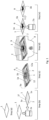
- Figure 1 provides an illustration of the steps involved in method for providing a conductive polymer material 9 on a fabric 1, according to a favourable embodiment of the present invention.
- the method comprises the steps of, (a) providing a fabric 1 and (b) impregnating the fabric with oxidant 2 using any suitable means.
- the fabric 1 may be woven or unwoven fabric, such as, for example, cotton, nylon, wool, paper, polyester, polyethylene any other suitable material; most preferably the fabric 1 will comprise fibres (i.e. most preferably the fabric will comprise a fibrous material).
- the fabric 1 is a wearable garment, such as pants, sweater, T-shirt, or the likes, which is to be provided with a conductive polymer material, in a predefined pattern or form (preferably a predefined 2-dimensional pattern or 2-dimensional form).
- Wearable garments used in the present invention such as T-shirts, typically comprise cotton fabric; other wearable garments used in the present invention, such as leggings, typically comprise nylon fabric, or spandex fabric. Because the conductive polymer material is electrically conductive, wearable garments which have been provided with a conductive polymer material using the method of the present invention, will have electronic capabilities enabling then to be used to form smart garments.
- the step (b) of impregnating the fabric 1 with oxidant may be performed using any suitable means.
- the step (b) of impregnating the fabric 1 with oxidant comprises submersing the fabric 1 in an oxidant solution 2a.
- the oxidant 2a will penetrate into the fabric 1, so that oxidant 2 which is in the oxidant solution 2a will become impregnated in the fabric 1. So, after step (b) has been performed oxidant 2 will be present both on the surface of the fabric 1 and also within the fabric 1 (i.e. between the fibres of the fabric, below the surface of the fabric).
- the fabric 1 is removed from the oxidant solution 2a and then dried.
- the fabric 1 may be allowed to dry passively, or, the fabric 1 may be actively dried using a dryer means (such as, a heater, a dehumidifier, or a ventilation cabinet, for example).
- a dryer means such as, a heater, a dehumidifier, or a ventilation cabinet, for example.
- the step of drying the fabric 1 is done in such a way to minimize contact with the fabric 1; contact with the fabric 1 after it has been removed from the oxidant solution 2a could result in removal of some of the impregnated oxidant 2 from the fabric 1 at the point of contact, so minimizing contact with the fabric 1 will ensure that a higher portion of the oxidant 2 will remain impregnated in the fabric 1.
- the fabric 1 may be positioned on a drying rack; the drying rack is preferably configured to hold (and thus contact) the fabric 1 at opposite ends 1d,1e of the fabric 1 only, so that the portion 1f of the fabric 1 which is between the opposite ends 1d,1e remain untouched by the drying rack.
- the fabric 1 is preferably dried using a drying rack; the drying rack preferably comprises a frame member which supports a plurality of rods, threads or wires, which are arranged to form a grid.
- the frame member of the drying rack may comprise any one of metal, plastic, and/or glass.
- Fabric 1 which is to be dried can be laid on the grid and arranged on the grid in such a way to ensure that the fabric 1 is without folds; alternatively, the fabric 1 which is to be dried can be hung over a rod, thread or wire, of the grid.
- the drying rack is then positioned in a well-ventilated area to allow solvent of the oxidant solution 2a to evaporate from the fabric 1; in an embodiment the fabric 1 is allowed to air dry on the drying rack for a period of time until dry.
- the drying rack is arranged to hold the fabric taut over a vessel, and oxidant solution 2a drips from the fabric 1 into the vessel where it is collected and may be reused.
- the fabric 1 While the fabric 1 is held on the drying rack the fabric 1 could, optionally, be exposed to an air flow so as to promote drying of the fabric 1.
- the fabric 1 preferably remains on the drying rack until the solvent of the oxidant solution 2a, which was absorbed into the fabric 1 when the fabric was submerged in the oxidant solution 2a in step (b), has evaporated and the fabric 1 is dry; the fabric 1 will retain the oxidant 2 on its surface and within the fabric (i.e. the oxidant 2 will be present both on the surface of the fabric 1 and also within the fabric 1 (i.e. between the fibres of the fabric, below the surface of the fabric)).
- the fabric 1 is heated so that the fabric 1 is actively dried; for example after the fabric 1 is removed from the oxidant solution 2a the fabric 1 may be placed in a drying oven and the temperature within the drying oven is adjusted to a suitable temperature which will promote the evaporation of the solvent of the oxidant solution, from the fabric 1, thereby leaving the fabric 1 dry and with the oxidant 2 remaining on the surface of the fabric 1 and within the fabric 1.
- the fabric 1 is exposed to an air flow; for example after the fabric 1 is removed from the oxidant solution 2a the fabric 1 may be placed in a ventilation cabinet where the fabric 1 will be exposed to a suitable air flow which will promote the evaporation of the solvent of the oxidant solution 2a, from the fabric 1, thereby leaving the fabric 1 dry and with the oxidant 2 remaining on the surface of the fabric 1 and within the fabric 1.
- a step (c) of applying a stencil 5 (most preferably a rigid stencil) having a cut-out 6, to the fabric 1, is carried out, so that at least some part 1a of the fabric 1 is covered by the stencil 5 and at least some other part 1b of the fabric 1 is exposed through the cut-out 6 of the stencil 5.
- a stencil 5 most preferably a rigid stencil having a cut-out 6,
- the stencil 5 may take any suitable form and the cut-out 6 may take any suitable form.
- the stencil 5 has a 'star-shaped' cut-out 6.
- the cut-out 6 in the stencil 5 has an interdigitated shape, as shown in Figure 3a .
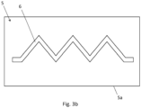
- the cut-out 6 in the stencil 5 has a zig-zag shape (or saw-tooth shape), as shown in Figure 3b .
- a stencil 5 which has cut-out 6 having a zig-zag shape enables the conductive polymer material 9 to be generated in shape which will ensure that the conductive polymer material 9 will define an electrode with a zig-zag profile, which can be used as a strain sensor.
- a strain sensor can be used to measure the strain within the fabric 1 when the fabric 1 is stretched for example.
- the electrical resistance of the zig-zag shaped electrode can be measured; when the fabric 1 is stretched the zig-zag shaped electrode will also be stretched together with the fabric 1; stretching of the zig-zag shaped electrode will reduce the electrical resistance of the zig-zag shaped electrode.
- the electrical resistance of the zig-zag shaped electrode can thus be used as an indicator of the amount of strain within the fabric 1 (caused by stretching the fabric).
- the cut-out 6 in the stencil 5 has a shape of a circular spiral or polygonal spiral, as shown in Figure 3c .
- a stencil 5 which has cut-out 6 having a circular spiral or polygonal spiral shape enables the conductive polymer material to be generated in shape which will ensure that the conductive polymer material will define an inductive coil and/or an antenna, which can be used for wireless communication.
- the stencil 5 fo have a cut-out 6; in an embodiment the stencil 5 has no cut-out 6.
- the method further comprises providing a support member 12 (preferably a rigid support member 12) and clamping the fabric 1 between the support member 12 and the stencil 5, so that the stencil 5 is held against fabric 1 with force.
- the fabric 1 may be positioned between a support member 12 and the stencil 5 and clips, screws, or magnets, can be applied to the support member 12 and stencil 5 which apply a force to the support member 12 and the stencil 5 to cause the support member 12 and the stencil 5 to clamp the fabric 1.
- the perimeter 12a of the support member 12 matches the perimeter 5a of the stencil 5 i.e. the dimensions of the perimeter 12a of the support member 12 match the dimensions of the perimeter 5a of the stencil 5.
- the support member 12 has a rectangular shape which matches the rectangular shape of the stencil 5.
- the stencil 5 which is used may have a planar profile.
- the fabric 1 is a sheet of fabric 1 that can be arranged in a planar profile, and the stencil 5 and also the support member 12 each have a planar profile.
- the stencil 5 used may have a curved profile corresponding to the profile of the surface of the fabric 1 (or corresponding to the profile of a portion of the surface of the fabric 1). If the fabric 1 which is to be provided with conductive polymer material 9 is in the form of a sock then the stencil 5 used may have a profile corresponding to the profile of a portion of a surface of the sock so as to allow the stencil 5 to fit snugly onto the sock, as illustrated in Figure 2 .
- the stencil 5 used may have a profile corresponding to the profile of a portion of a surface of the of the glove, so as to allow the stencil 5 to fit snugly onto that portion of the surface of the glove.
- the stencil 5 may comprise any suitable material.
- the stencil 5 may comprise any one or more of polymethylmethacrylate, and/or polylactic acid, and/or polyethylene, and/or polyether ether ketone, and/or metal (such as sheet metal), and/or stainless steel, and/or aluminium.
- the method further comprises providing a support member 12 (preferably a rigid support member) and then positioning the fabric 1 on the support member 12 (or mounting the fabric 1 on the support member 12).
- a support member 12 preferably a rigid support member
- the fabric 1 is in the form of a wearable garment
- the wearable garment is mounted onto the support member 12.
- the support member 12 has a suitable 3-D profile so that it can receive the wearable garment (most preferably the support member has a curved profile matching the profile of the inside of the wearable garment or, at least, matching the profile of a portion of the inside of the wearable garment).
- the support member 12 may have a shape corresponding to a portion of the inside of a sock if the wearable garment is a sock; the support member 12 may have a cylindrical shape, corresponding to the inside of a sleeve, if the wearable garment is a sleeve of a sweater; the support member may have a shape resembling a hand, if the wearable garment is a glove.
- Providing a support member 12 which has a suitable 3-D profile so that it can receive the wearable garment allows for a snug fit of the wearable garment on the support member 12.
- the stencil 5 will preferably have a suitable 3-D profile so that it can be placed on at least a part of the wearable garment when the wearable garment is mounted on the support member 12.
- the stencil 5 may have a cylindrical profile or semi-cylindrical profile if the wearable garment a sleeve of a sweater, or a sock, or a glove; in another example, the stencil 5 may have a substantially L-shaped profile with semi-cylindrical cross section, if the wearable garment is a sock.
- the method will comprise the steps of mounting the wearable garment onto the support member 12 so that the support member 12 contacts an inside surface of the wearable garment; then applying the stencil 5 onto an outer surface of the wearable garment, so that the wearable garment is sandwiched between the support member 12 and the stencil 5, the support member being in contact with the inside surface of the wearable garment and the stencil 5 being in contact with and overlaying at least portion of the outer surface of the wearable garment.
- This embodiment facilitates providing a conductive polymer material 9 on a surface of a fabric 1 which has a non-planar profile (e.g.
- this embodiment facilitates providing a conductive polymer material 9 on a surface of wearable garments without having to unstitch/dismantle the wearable garments.
- a step (d) of exposing the fabric 1 to a monomer vapor 7 so that the monomer vapor 7 reacts with the oxidant 2 impregnated in the fabric 1 to generate a conductive polymer material 9 on the fabric 1 and within the fabric 1, is carried out.
- the conductive polymer material 9 which is generated on the fabric 1 and within the fabric 1, is electrically conductive.
- the part 1a of the fabric 1 which is covered by the stencil 5 will not be exposed to the monomer vapor 7, while the other part 1b of the fabric 1 is exposed to the monomer vapor 7 through the cut-out 6 of the stencil 5; as a result, the conductive polymer material 9 is generated only on and within the part 1b of the fabric 1 which is exposed to the monomer vapor 7 through the cut-out 6 of the stencil 5. Consequently the 2-dimensional shape of the conductive polymer material 9 which is generated only on and within the part 1b of the fabric 1, will correspond to the 2-dimensional shape of the cut-out 6 in the stencil 5.
- the 2-dimensional shape of the cut-out 6 is a star-shape, consequently the conductive polymer material 9 which is generated only on and within the part 1b of the fabric 1 is star-shaped (however it should be understood that the cut-out 6 could have any suitable shape).
- the monomer vapor 7 reacts both with the oxidant 2 on the surface of the fabric 1 and also with the oxidant 2 that is within the fabric 1 (i.e. oxidant 2 that is below the surface of the fabric 1, between the fibres of the fabric 1), so that a conductive polymer material 9 is generated both on the surface of the part 1b of the fabric 1 which is exposed to the monomer vapor 7 through the cut-out 6 of the stencil 5, and, also within the fabric 1 (i.e. below the surface of the fabric, between the fibres of the fabric) of the part 1b of the fabric which is exposed to the monomer vapor 7 through the cut-out 6 of the stencil 5.
- the generated conductive polymer material 9 will be 3-dimensional, penetrating into the fabric 1 to below the surface of the fabric 1, but will have a 2-dimensional shape which corresponds to the 2-dimensional shape cut-out 6 of the stencil 5.
- the monomer vapor 7 may have any suitable composition.
- the monomer vapor 7 may be a conductive monomer vapor 7, such as pyrrole, and/or pyrrole's derivatives such as pyrrole's alkyl, and/or alkoxy, and/or hydroxyl, and/or carboxyl derivatives (e.g. 1-methylpyrrole); and/or aniline, including aniline's derivatives such as aniline's alkyl, and/or alkoxy, and/or hydroxyl, and/or carboxyl derivatives (e.g.
- thiophene including thiophene's derivatives such as thiophene's alkyl, and/or alkoxy, and/or hydroxyl, and/or carboxyl derivatives (e.g. 3,4-ethylenedioxythiophene).
- the monomer vapor 7 is provided by a precursor to the monomer vapor 7.
- a precursor to the monomer vapor 7 is a chemical compound in a solid or liquid state which can release the monomer vapor 7.
- the monomer vapor 7 will preferably provide a partial vapor pressure of at least 5 mmHg of a total vapor pressure of 1 atm. Most preferably the monomer vapor 7 will provide a partial vapor pressure between 5 mmHg-10 mmHg of a total vapor pressure of 1 atm.
- a partial vapor pressure between 5 mmHg-10 mmHg facilitates the monomer vapor to polymerize the oxidant 2 that is on and within the fabric 1, so as to form the conductive polymer material 9 on and within the fabric 1.
- the precursor to the monomer vapor 7 releases enough monomer vapor 7 when the precursor is at 20°C (or at room temperature) so that the monomer vapor 7 will provide a partial vapor pressure between 5 mmHg-10 mmHg of a total vapor pressure of 1 atm.
- the precursor needs to be heated to a temperature which is above 20°C (or above room temperature), so that the precursor releases enough monomer vapor 7 sufficient to ensure that the monomer vapor 7 will provide a partial vapor pressure between 5 mmHg-10 mmHg of a total vapor pressure of 1 atm.
- Increasing the temperature of precursor to the monomer vapor 7 i.e.
- the monomer vapor 7 may have any suitable composition (the invention is not limited to requiring the monomer vapor 7 to comprise pyrrole vapor and/or aniline vapor).
- the temperature to which any precursor to a suitable monomer vapor 7 should be heated to in order to provide a partial vapor pressure between 5 mmHg-10 mmHg, is known in the art.
- the monomer vapor 7 may comprise pyrrole; a precursor to pyrrole vapor (e.g. pyrrole in a liquid or solid state) is provided at 20°C (or at room temperature), and at this temperature the precursor provides a pyrrole vapor (monomer vapor 7) which exhibits a partial vapor pressure of 7 mmHg of a total vapor pressure of 1 atm.
- the monomer vapor 7 may comprise aniline; a precursor to aniline vapor (e.g.
- aniline in a liquid or solid state is provided; when the precursor to aniline vapor is at 20°C (or room temperature) the aniline vapor released by the precursor provides only a partial vapor pressure of less than 1 mmHg, which is outside of the desired partial vapor pressure range between 5 mmHg-10 mmHg; accordingly the precursor to aniline vapor is preferably heated to a predefined, known, temperature which is above 20°C (above room temperature) so that the aniline vapor provided by the precursor provides a partial vapor pressure of between 5 mmHg-10 mmHg of a total vapor pressure of 1 atm.
- the precursor to aniline vapor is heated to a temperature of 69°C; at a temperature of 69°C the precursor to aniline vapor provides an aniline vapor which exhibits a partial vapor pressure of 10 mmHg of a total vapor pressure of 1 atm.
- step (d) of exposing the fabric 1 to a monomer vapor 7 comprises placing the fabric in a chamber 8 (such as a desiccator); then closing the chamber 8, preferably so that the chamber is air-tight (i.e. the fabric is contain in an air tight chamber 8).
- a chamber 8 such as a desiccator
- the monomer vapor 7 is provided inside the chamber 8 so that the part 1b of the fabric 1 which is exposed through the cut-out 6 of the stencil 5 is exposed to the monomer vapor 7.
- a precursor of the monomer vapor 7 is provided inside the chamber 8, in liquid or solid form, and this precursor provides the monomer vapor 7 within the chamber 8 (i.e. the precursor releases monomer vapor 7 into the chamber 8).
- the precursor to the monomer vapor 7 releases the monomer vapor 7 when the precursor is at 20°C (or at room temperature); in this embodiment when the temperature inside the chamber 8 is at 20°C (or at room temperature) the precursor to the monomer vapor 7 can simply be placed inside the chamber 8 and will release the monomer vapor 7 into chamber 8 without requiring any heating.
- the precursor needs to be heated to a temperature which is above 20°C (or above room temperature), before it releases a sufficient amount of the monomer vapor 7; in this embodiment the precursor to the monomer vapor 7 is first placed inside the chamber 8 and the precursor is then heated to a predefined temperature which is above 20°C (or above room temperature) while in the chamber 8, to cause the precursor to release the monomer vapor 7 into the chamber 8.
- the monomer vapor 7 provided inside the chamber 8 will provide a partial vapor pressure between 5 mmHg-10 mmHg of a total vapor pressure of 1 atm inside the chamber 8.
- the monomer vapor 7 may have any suitable composition (the invention is not limited to requiring the monomer vapor 7 to comprise pyrrole vapor and/or aniline vapor).
- the temperature to which any precursor to a suitable monomer vapor 7 should be heated to in order to provide a partial vapor pressure between 5 mmHg-10 mmHg, is known in the art.
- the monomer vapor 7 may comprise pyrrole; in this case the inside of the chamber 8 is set to be 20°C (or at room temperature); and a precursor to pyrrole vapor (in a liquid or solid state) is provided inside the chamber 8. At 20°C (or at room temperature) the precursor to pyrrole vapor releases a pyrrole vapor, which defines the monomer vapor 7, which exhibits a partial vapor pressure of 7 mmHg of a total vapor pressure of 1 atm inside the chamber 8. Thus, in this embodiment the precursor does not need to be heated.
- a partial vapor pressure of 7 mmHg facilitates the pyrrole vapor to polymerize the oxidant 2 that is on and within the fabric 1, so as to form the conductive polymer material 9 on and within the fabric 1.
- the precursor to pyrrole vapor may be heated to a temperature above 20°C; for example, the precursor to pyrrole vapor may be heated to a temperature between 20°C - 30°C.
- the monomer vapor 7 may comprise aniline; in this case a precursor to aniline vapor (in a liquid or solid state) is provided inside the chamber 8; the precursor to aniline vapor is preferably heated to a temperature of 69°C; at a temperature of 69°C the precursor to aniline vapor provides an aniline vapor which exhibits a partial vapor pressure of 10 mmHg of a total vapor pressure of 1 atm inside the chamber 8.
- a partial vapor pressure of 10 mmHg facilitates the aniline vapor to polymerize the oxidant 2 that is on and within the fabric 1, so as to form the conductive polymer material 9 on and within the fabric 1.
- the precursor to aniline vapor may be heated to a temperature above 69°C; for example, the precursor to aniline vapor may be heated to a temperature between 70°C -180°C.
- the monomer vapor 7 which in the chamber 8 is 3,4-ethylenedioxythiophene vapor; in this case a precursor to 3,4-ethylenedioxythiophene vapor (in a liquid or solid state) is provided inside the chamber 8; then the precursor to 3,4-ethylenedioxythiophene vapor is heated to a temperature in the range 150°C -300°C to provide a 3,4-ethylenedioxythiophene vapor which has a sufficiently high partial vapor pressure of the total vapor pressure inside the chamber 8, to facilitate the 3,4-ethylenedioxythiophene vapor to polymerize the oxidant 2 that is on and within the fabric 1, so as to form the conductive polymer material 9 on and within the fabric 1.
- the precursor releases the monomer vapor 7 the part 1b of the fabric 1 which is exposed through the cut-out 6 of the stencil 5 is exposed to the monomer vapor 7 inside the chamber 8.
- the monomer vapor 7 will polymerize the oxidant 2 that is on and within the part 1b of the fabric 1, so as to form the conductive polymer material 9 on and within the part 1b of the fabric 1.
- a partial vapor pressure between 5 mmHg-10 mmHg facilitates the monomer vapor to polymerize the oxidant 2.
- the method comprises providing a vacuum within the chamber 8.
- the method comprises providing a vacuum within the chamber 8 so as to remove all gases and vapours from inside the chamber 8 so that the monomer vapor 7 is the only vapor inside the chamber.
- the precursor of the monomer vapor 7 is provided inside the chamber 8. Since all gases and vapour were removed from the chamber 8 by the vacuum, the only vapor in the chamber 8 is the monomer vapor 7 which is provided by the precursor of the monomer vapor 7. Consequently, all of the vapor pressure inside the chamber 8 will be provided solely by the monomer vapor 7 since there are no other gases or vapours within the chamber 8 to contribute to the total vapor pressure within the chamber 8.
- This embodiment can remove the need to heat the precursor to the monomer vapor 7 to achieve a monomer vapor pressure which will facilitate the monomer vapor 7 to polymerize the oxidant 2 that is on and within the fabric 1, so as to form the conductive polymer material 9 on and within the fabric 1.
- the precursor to aniline vapor in a liquid or solid state
- the precursor to aniline vapor will provide aniline vapor which provides a vapor pressure of 10 mmHg inside the chamber, without the need to heat the precursor; a vapor pressure of 10 mmHg facilitates the aniline vapor to polymerize the oxidant 2 that is on and within the fabric 1, so as to form the conductive polymer material 9 on and within the fabric 1.
- the method comprises decreasing the pressure within the chamber 8 so as to reduce the temperature to which a precursor to the monomer vapor 7 needs to be heated to provide sufficient amount of monomer vapor 7 inside the chamber 8, so that monomer vapor 7 provides a partial vapor pressure between 5 mmHg-10 mmHg of a total vapor pressure of 1 atm inside the chamber 8. Most preferably the method comprises decreasing the pressure within the chamber 8 so that the pressure within the chamber 8 is less than 1atm.
- the pressure within the chamber 8 is decreased and the precursor is heated to provide sufficient monomer vapor 7; the decreased pressure within the chamber 8 reduces the temperature to which the precursor of the monomer vapor 7 needs to be heated to in order to achieve a monomer vapor pressure which will facilitate the monomer vapor 7 to polymerize the oxidant 2 that is on and within the fabric 1, so as to form the conductive polymer material 9 on and within the fabric 1.
- the temperature which a precursor to the monomer vapor 7 needs to be heated to depends on the composition of the precursor and also on the pressure inside the chamber 8; typically, the more the pressure inside the chamber 8 is decreased the lower the temperature to which the precursor will need to be heated to in order to provide a suitable amount of monomer vapor 7 within the chamber 8.
- the pressure inside the chamber 8 should be decreased to a level, and the precursor of the monomer vapor 7 heated to a temperatures, which is sufficient to cause the precursor to provide a sufficient amount of monomer vapor inside the chamber 8 so that the monomer vapor pressure inside the chamber 8 is sufficient to facilitate the monomer vapor 7 to polymerize the oxidant 2 that is on and within the fabric 1, so as to form the conductive polymer material 9 on and within the fabric 1.
- the method preferably, comprises a step (e) of retrieving the oxidant 2 that is impregnated in the part 1a of fabric 1, which was covered by the stencil 5, for reuse.
- the step (e) of retrieving the oxidant 2 may be done using any suitable means.
- the step (e) of retrieving the oxidant 2 comprises submersing the fabric 1 in a suitable solvent 2a'; when the fabric is submersed in a suitable solvent 2a' the oxidant 2 that is on and within the part 1a of fabric 1 will dissolve in the solvent 2a', to form an oxidant solution 2a.
- suitable solvents 2a' include, but are not limited to, methanol, and/or ethanol, and/or water, and/or any combination of one or more of said aforementioned; most preferably the solvent 2a' comprises methanol.
- the solvent 2a' which is used will depend on the chemical characteristics of the oxidant 2 which is impregnated in the part 1a of fabric 1 (i.e.
- the solvent 2a' which is used will depend on the chemical characteristic of the oxidant 2 which is to be retrieved from the part 1a of fabric 1); for example methanol, acetone, isopropyl alcohol can be used as solvent to dissolve FeCl 3 oxidant; in another example water can be used as a solvent; water is a cheaper and environmentally friendly solvent 2a'.
- the method involves moving (stirring and/agitating), manually and/or using suitable mechanical means, the fabric 1 when it is submersed in the solvent 2a' so as to promote the movement of the oxidant 2 from the part 1a of fabric 1 into the solvent 2a'.
- the method may further comprise heating said oxidant solution 2a, so that some of the solvent evaporates, to bring the oxidant solution 2a to a predefined oxidant concentration. Evaporating the solvent will increase the oxidant concentration of the oxidant solution 2a.
- step (e) of retrieving the oxidant 2 comprises submersing the fabric 1 in the same solution 2a as was used in step (b); the oxidant 2 will move out of the part 1a of the fabric 1 and into the oxidant solution 2a thereby increasing the concentration of oxidant in the oxidant solution 2a.
- the resulting oxidant solution 2a forms an oxidant solution 2a which can be reused (e.g.
- the oxidant solution 2a may then be heated, so that some of the solvent evaporates, to bring the oxidant solution 2a to a predefined oxidant concentration before the oxidant solution 2a is reused; most preferably, the oxidant solution 2a is heated to bring the oxidant solution 2a to the same oxidant concentration as the concentration the oxidant solution 2a initially had, prior to submersing the fabric 1 in the oxidant solution 2a in the step (b). Evaporating the solvent will increase the oxidant concentration of the oxidant solution 2a.
- the conductive polymer material 9 may be doped. Doping the conductive polymer can be done by any suitable means.
- the method further comprises a step of adding dopant to the oxidant solution 2a before submersing the fabric 1 in the oxidant solution 2a in step (b). Then when step (b) is carried out the fabric 1 is submersed in the doped oxidant solution; the fabric 1 will thus be impregnated with both oxidant 2 and dopant.
- step (d) when step (d) is carried out (wherein the monomer vapor 7 reacts with the oxidant impregnated in the fabric) the dopant will be present in the generated conductive polymer material 9; so step (d) will result in a doped conductive polymer material 9 being generated on and within the fabric 1.
- the method comprises doping the conductive polymer material 9 with a dopant after it has been generated on and within the fabric 1.
- the method may further comprise a step of doping the conductive polymer material 9 with a dopant.
- the conductive polymer material 9 may be doped using any suitable means.
- the method may further comprise providing a solution which comprises the dopant (i.e. providing a dopant solution); then after the conductive polymer material 9 has been generated on and within the fabric 1 (e.g. after step (d) has been carried out), then submersing the conductive polymer material 9 which is on and within the fabric 1 in said dopant solution.
- the conductive polymer material 9 is submersed in the dopant solution the dopant which is in the solution will be absorbed into the conductive polymer material 9 to dope conductive polymer material 9.
- the dopant used in any of the embodiments of the present invention may take any suitable form.
- the dopant is preferably a material that will improve predefined properties of the conductive polymer material 9 which is generated on and within the fabric 1.
- the dopant may comprise, any one or more of, p-toluene sulfonate, chondroitin sulfate, dodecylbenzenesulfonate, anthraquinone sulfonate, camphorsulfonic acid.
- an stencil 5 is not essential to the present invention i.e. the step (c) of applying a stencil 5 having a cut-out 6, to the fabric 1, is not essential to the present invention (and it follows that any subsequent steps relating to the stencil 5 of the above mentioned embodiments, are also not essential to the present invention).
- the stencil 5 is used to restrict the parts of the fabric which are provided with conductive polymer material 9 and/or to ensure that the conductive polymer material 9 will have a predefined 2-dimensional form/shape on the fabric 1.
- the whole of the fabric 1 (or the whole of a section of a fabric 1) is to be provided with conductive polymer material 9 then there is no need to use a stencil 5 and thus there is no need to perform a step (c) of applying a stencil 5 having a cut-out 6, to the fabric 1.
- the fabric 1 is to be provided with conductive polymer material 9 in any form/shape then, again in this scenario, there is no need to use a stencil 5 and thus there is no need to perform a step (c) of applying a stencil 5 having a cut-out 6, to the fabric 1.
- the stencil 5 which is used in step (c) has no cut-out 6.
- the stencil 5 will be arranged to cover some part of the fabric 1 leaving another part of the fabric exposed.
- the conductive polymer material 9 will be provided on the exposed part of the fabric 1.
- the stencil 5 may comprise a plurality of mechanically independent pieces which can be individually applied to the surface of the fabric 1.
- the method may further comprise a step of arranging the plurality of pieces in a predefined pattern on the fabric 1.
- the conductive polymer material 9 will be provided on the part(s) of the fabric 1 which are not covered by any of the plurality of pieces.
- the monomer vapor 7 used in any of the embodiments of the present invention may comprises one or more of, either pyrrole, aniline, thiophene, and/or any derivatives of the aforementioned compounds, such as, for example, pyrrole, including its alkyl, alkoxy, hydroxyl, carboxyl derivatives (e.g. 1-methylpyrrole); aniline, including its alkyl, alkoxy, hydroxyl, carboxyl derivatives (e.g. o-aminophenol); thiophene, including its alkyl, alkoxy, hydroxyl, carboxyl derivatives (e.g. 3,4-ethylenedioxythiophene).
- pyrrole including its alkyl, alkoxy, hydroxyl, carboxyl derivatives (e.g. 1-methylpyrrole)
- aniline including its alkyl, alkoxy, hydroxyl, carboxyl derivatives (e.g. o-aminophenol)
- thiophene including its alkyl
- the oxidant 2 used in any of the embodiments of the present invention may comprise one or more of, ferric chloride, ammonium persulfate, ammonium dichromate, chloroauric acid, potassium permanganate, iron(III) salts of p-toluenesulfonic acid, dodecylbenzenesulfonic acid, 4-morpholinepropanesulfonic acid, 3-pyridinesulfonic acid.
- a further advantage of the method of the present invention is that it can be used to provide a conductive polymer material on a fabric which has a non-planar profile.
- the method of the present invention can thus be used to provide a conductive polymer material directly on to any part of an existing wearable garment without the need to unstitch/dismantle the garment.
- the method of the present invention can thus be used to provide a conductive polymer material directly on to a sock, sweater/pullover, sleeve, or glove for example, without having to unstitch/dismantle the sock, sweater/pullover, sleeve, or glove.
- the method of the present invention can be used to provide a conductive polymer material directly on finger portion of a glove, which has a cylindrical profile, without having to unstitch/dismantle the finger portion of the glove to make a finger portion into a planar profile.
- the method of the present invention can easily be incorporated into existing wearable textile manufacturing processes because it does not require any adaptation of the existing manufacturing steps, rather the method of the present invention is an add-on which can be used when it is desired to transform the already manufactured wearable textiles into wearable textiles with electronic capability (e.g. to form smart wearable textiles).
- Figure 2 illustrates a method of the present invention used to provide a conductive polymer material 9 on a fabric 1 in the form of a sock 1.
- the method illustrated in Figure 2 is similar to the method illustrated in Figure 1 and like features are awarded the same reference numbers.
- the stencil 5 used has a profile which corresponds to the profile of an outside surface 20 of the sock 1.
- the stencil 5 used has a substantially L-shaped profile with a substantially semi-cylindrical cross section corresponding to the profile of an outside surface 20 of the sock 1.
- the support member 12 has a shape corresponding to the profile of an inside surface of the sock 1.
- the step (c) comprise mounting the sock onto the support member 12 so that the support member 12 contacts an inside surface of the sock 1; in this particular example the support member 12 is pushed inside the sock 1 so that the support member 12 contacts an inside surface of the sock 1.
- the size of the support member 12 is preferably substantially equivalent to the volume inside the sock 1, so that when the support member 12 will fit snugly inside the sock when the support member 12 is pushed inside the sock 1.
- the stencil 5 is then applied to the outer surface 20 of the sock so that the sock is sandwiched between the support member 12 and the stencil 5, the support member 12 being in contact with the inside surface of the sock 1 and the stencil 5 being in contact with and overlaying at least part of the outer surface 20 of the sock 1.
- the methods of the present invention may be used to form a wearable textile capacitor.
- the fabric which is used when performing the steps of any of the above-mentioned embodiments is a wearable garment; and the stencil 5 which is used a has cut-out 6 having an interdigitated shape.
- the methods of the present invention may be used to form a wearable textile strain sensor.
- the fabric which is used when performing the steps of any of the above-mentioned embodiments is a wearable garment; and the stencil 5 which is used a has cut-out 6 having a zig-zag shape (or saw-tooth shape).
- the methods of the present invention may be used to form a wearable antenna and/or induction coil.
- the fabric which is used when performing the steps of any of the above-mentioned embodiments is a wearable garment; and the stencil 5 with the cut-out 6 in form of a circular spiral or polygonal spiral.
- Providing a wearable garment with an antenna will enable wireless communication between the wearable garment and another electronic device (such as a mobile device, like, for example, a smart watch or smart phone, or the likes).
Landscapes
- Engineering & Computer Science (AREA)
- Textile Engineering (AREA)
- Chemical & Material Sciences (AREA)
- Chemical Kinetics & Catalysis (AREA)
- Dispersion Chemistry (AREA)
- Treatment Of Fiber Materials (AREA)
- Treatments For Attaching Organic Compounds To Fibrous Goods (AREA)
Abstract
According to the present invention there is provided a method for providing a conductive polymer material (9) on a fabric (1), the method comprising the steps of, (a) providing a fabric (1); (b) impregnate the fabric (1) with oxidant (2); (c) exposing the fabric (1) to a monomer vapor (7) so that the monomer vapor (7) reacts with the oxidant (2) impregnated in the fabric (1) to generate a conductive polymer material (9) on the fabric (1). There is further provided a fabric comprising a conductive polymer material formed using the method of the present invention.
Description
- The present invention concerns a method for providing a conductive polymer material on a fabric which involves impregnating the fabric with oxidant and then exposing the fabric to a monomer vapor.
- The application of conductive material to fabrics is becoming increasing important with the advent of electronic wearable garments (such as, for example, e-textiles and smart garments). Such wearable garments are provided with conductive material which, for example, may serve as a flat antenna, concentric windings, capacitors (such as interdigitated capacitors), and/or electrodes to support higher levels of integration to wearable technology devices.
- However, existing methods for providing conductive material onto fabrics are inadequate. Existing methods for applying conductive material to fabrics include screen-printing and inkjet printing of conductive inks (comprising conductive carbon or polymers) on the fabric. These existing methods involve multiple complicated steps, are expensive to set up, waste large amounts of materials, and typically only work well when the conductive material/ink is applied to a flat surface of the fabric. These limitations of existing methods make them unsuitable for mass producing electronic wearable garments (such as, for example, e-textiles and smart garments).
- Furthermore, the existing methods cannot be easily introduced into existing fabric manufacturing processes and are also unsuitable for applying conductive material to existing wearable garments so are not useful to adapt existing wearable garments to make them smart garments.
- Also, some of existing methods used to apply conductive material to fabric do not apply the conductive material in a way to make it robust enough to withstand subsequent bending and stretching without loss of function and performance.
- An aim of the present invention to obviate or mitigate at least some of the disadvantages associated with existing methods used to apply conductive material to fabric.
- According to the present invention, this aim is achieved by a method having the steps recited in
independent claim 1. The dependent claims recite favourable, optional, features of various embodiments of the inventions. - Exemplary embodiments of the invention, given by way of example only, will be described in the detailed description, with reference to the following drawings in which:
-
Figure 1 provides an illustration of the steps involved in a method according to an embodiment of the present invention; -
Figure 2 provides an illustration of the steps involved in a method according to the present invention, wherein the fabric is in the form of wearable garment (a sock), and the method involves mounting the sock on a support, and involves using a stencil which has a curved profile corresponding to a profile of a portion of an outer surface the sock; -
Figure 3a shows an example of a stencil which can be used when performing the method of the present invention;Figure 3b shows another example of a stencil which can be used when performing the method of the present invention. -
Figure 1 provides an illustration of the steps involved in method for providing aconductive polymer material 9 on afabric 1, according to a favourable embodiment of the present invention. In this embodiment the method comprises the steps of, (a) providing afabric 1 and (b) impregnating the fabric withoxidant 2 using any suitable means. - The
fabric 1 may be woven or unwoven fabric, such as, for example, cotton, nylon, wool, paper, polyester, polyethylene any other suitable material; most preferably thefabric 1 will comprise fibres (i.e. most preferably the fabric will comprise a fibrous material). In an embodiment thefabric 1 is a wearable garment, such as pants, sweater, T-shirt, or the likes, which is to be provided with a conductive polymer material, in a predefined pattern or form (preferably a predefined 2-dimensional pattern or 2-dimensional form). Wearable garments used in the present invention, such as T-shirts, typically comprise cotton fabric; other wearable garments used in the present invention, such as leggings, typically comprise nylon fabric, or spandex fabric. Because the conductive polymer material is electrically conductive, wearable garments which have been provided with a conductive polymer material using the method of the present invention, will have electronic capabilities enabling then to be used to form smart garments. - The step (b) of impregnating the
fabric 1 with oxidant may be performed using any suitable means. Preferably, the step (b) of impregnating thefabric 1 with oxidant comprises submersing thefabric 1 in anoxidant solution 2a. It should be understood that in step (b) theoxidant 2a will penetrate into thefabric 1, so thatoxidant 2 which is in theoxidant solution 2a will become impregnated in thefabric 1. So, after step (b) has been performedoxidant 2 will be present both on the surface of thefabric 1 and also within the fabric 1 (i.e. between the fibres of the fabric, below the surface of the fabric). - Preferably after the
fabric 1 has been submersed in theoxidant solution 2a, thefabric 1 is removed from theoxidant solution 2a and then dried. Thefabric 1 may be allowed to dry passively, or, thefabric 1 may be actively dried using a dryer means (such as, a heater, a dehumidifier, or a ventilation cabinet, for example). Most preferably, the step of drying thefabric 1 is done in such a way to minimize contact with thefabric 1; contact with thefabric 1 after it has been removed from theoxidant solution 2a could result in removal of some of the impregnatedoxidant 2 from thefabric 1 at the point of contact, so minimizing contact with thefabric 1 will ensure that a higher portion of theoxidant 2 will remain impregnated in thefabric 1. - For example, in one embodiment after the
fabric 1 is removed from the oxidant solution 2b thefabric 1 may be positioned on a drying rack; the drying rack is preferably configured to hold (and thus contact) thefabric 1 atopposite ends 1d,1e of thefabric 1 only, so that theportion 1f of thefabric 1 which is between theopposite ends 1d,1e remain untouched by the drying rack. Thefabric 1 is preferably dried using a drying rack; the drying rack preferably comprises a frame member which supports a plurality of rods, threads or wires, which are arranged to form a grid. The frame member of the drying rack may comprise any one of metal, plastic, and/or glass.Fabric 1 which is to be dried can be laid on the grid and arranged on the grid in such a way to ensure that thefabric 1 is without folds; alternatively, thefabric 1 which is to be dried can be hung over a rod, thread or wire, of the grid. The drying rack is then positioned in a well-ventilated area to allow solvent of theoxidant solution 2a to evaporate from thefabric 1; in an embodiment thefabric 1 is allowed to air dry on the drying rack for a period of time until dry. Most preferably the drying rack is arranged to hold the fabric taut over a vessel, andoxidant solution 2a drips from thefabric 1 into the vessel where it is collected and may be reused. While thefabric 1 is held on the drying rack thefabric 1 could, optionally, be exposed to an air flow so as to promote drying of thefabric 1. Thefabric 1 preferably remains on the drying rack until the solvent of theoxidant solution 2a, which was absorbed into thefabric 1 when the fabric was submerged in theoxidant solution 2a in step (b), has evaporated and thefabric 1 is dry; thefabric 1 will retain theoxidant 2 on its surface and within the fabric (i.e. theoxidant 2 will be present both on the surface of thefabric 1 and also within the fabric 1 (i.e. between the fibres of the fabric, below the surface of the fabric)). - Alternatively, in another embodiment after the
fabric 1 is removed from theoxidant solution 2a thefabric 1 is heated so that thefabric 1 is actively dried; for example after thefabric 1 is removed from theoxidant solution 2a thefabric 1 may be placed in a drying oven and the temperature within the drying oven is adjusted to a suitable temperature which will promote the evaporation of the solvent of the oxidant solution, from thefabric 1, thereby leaving thefabric 1 dry and with theoxidant 2 remaining on the surface of thefabric 1 and within thefabric 1. In another embodiment after thefabric 1 is removed from theoxidant solution 2a thefabric 1 is exposed to an air flow; for example after thefabric 1 is removed from theoxidant solution 2a thefabric 1 may be placed in a ventilation cabinet where thefabric 1 will be exposed to a suitable air flow which will promote the evaporation of the solvent of theoxidant solution 2a, from thefabric 1, thereby leaving thefabric 1 dry and with theoxidant 2 remaining on the surface of thefabric 1 and within thefabric 1. - In this embodiment, next, a step (c) of applying a stencil 5 (most preferably a rigid stencil) having a cut-out 6, to the
fabric 1, is carried out, so that at least somepart 1a of thefabric 1 is covered by thestencil 5 and at least someother part 1b of thefabric 1 is exposed through the cut-out 6 of thestencil 5. - It should be understood that the
stencil 5 may take any suitable form and the cut-out 6 may take any suitable form. In the embodiment illustrated inFigure 1 (andFigure 2 ) thestencil 5 has a 'star-shaped' cut-out 6. In another embodiment the cut-out 6 in thestencil 5 has an interdigitated shape, as shown inFigure 3a . Using astencil 5 which has cut-out 6 having an interdigitated shape enables theconductive polymer material 9 to be generated in a shape which will ensure that theconductive polymer material 9 will define an interdigital capacitor (having two electrodes and a dielectric separator) and/or one or more interdigitated electrodes on and within thefabric 1. - In another embodiment the cut-out 6 in the
stencil 5 has a zig-zag shape (or saw-tooth shape), as shown inFigure 3b . Using astencil 5 which has cut-out 6 having a zig-zag shape enables theconductive polymer material 9 to be generated in shape which will ensure that theconductive polymer material 9 will define an electrode with a zig-zag profile, which can be used as a strain sensor. Such a strain sensor can be used to measure the strain within thefabric 1 when thefabric 1 is stretched for example. During use, the electrical resistance of the zig-zag shaped electrode can be measured; when thefabric 1 is stretched the zig-zag shaped electrode will also be stretched together with thefabric 1; stretching of the zig-zag shaped electrode will reduce the electrical resistance of the zig-zag shaped electrode. The electrical resistance of the zig-zag shaped electrode can thus be used as an indicator of the amount of strain within the fabric 1 (caused by stretching the fabric). - In another embodiment the cut-out 6 in the
stencil 5 has a shape of a circular spiral or polygonal spiral, as shown inFigure 3c . Using astencil 5 which has cut-out 6 having a circular spiral or polygonal spiral shape enables the conductive polymer material to be generated in shape which will ensure that the conductive polymer material will define an inductive coil and/or an antenna, which can be used for wireless communication. - It should be understood that it is not essential for the
stencil 5 fo have a cut-out 6; in an embodiment thestencil 5 has no cut-out 6. - In the embodiment illustrated in
Figure 1 , the method further comprises providing a support member 12 (preferably a rigid support member 12) and clamping thefabric 1 between thesupport member 12 and thestencil 5, so that thestencil 5 is held againstfabric 1 with force. For example, thefabric 1 may be positioned between asupport member 12 and thestencil 5 and clips, screws, or magnets, can be applied to thesupport member 12 andstencil 5 which apply a force to thesupport member 12 and thestencil 5 to cause thesupport member 12 and thestencil 5 to clamp thefabric 1. Preferably, theperimeter 12a of thesupport member 12 matches theperimeter 5a of thestencil 5 i.e. the dimensions of theperimeter 12a of thesupport member 12 match the dimensions of theperimeter 5a of thestencil 5. In the embodiment shown inFigure 1 , thesupport member 12 has a rectangular shape which matches the rectangular shape of thestencil 5. - In the
case fabric 1 which is to be provided withconductive polymer material 9 can be arranged in a planar profile (e.g. a sheet of fabric), then thestencil 5 which is used may have a planar profile. In the embodiment shown inFigure 1 thefabric 1 is a sheet offabric 1 that can be arranged in a planar profile, and thestencil 5 and also thesupport member 12 each have a planar profile. - In case the
fabric 1 which is to be provided withconductive polymer material 9 has a non-planar profile (e.g. a sleeve of a wearable garment, which has a cylindrical profile) then thestencil 5 used may have a curved profile corresponding to the profile of the surface of the fabric 1 (or corresponding to the profile of a portion of the surface of the fabric 1). If thefabric 1 which is to be provided withconductive polymer material 9 is in the form of a sock then thestencil 5 used may have a profile corresponding to the profile of a portion of a surface of the sock so as to allow thestencil 5 to fit snugly onto the sock, as illustrated inFigure 2 . If thefabric 1 which is to be provided with conductive polymer material is in the form of a glove, then thestencil 5 used may have a profile corresponding to the profile of a portion of a surface of the of the glove, so as to allow thestencil 5 to fit snugly onto that portion of the surface of the glove. - In the present invention the
stencil 5 may comprise any suitable material. For example, thestencil 5 may comprise any one or more of polymethylmethacrylate, and/or polylactic acid, and/or polyethylene, and/or polyether ether ketone, and/or metal (such as sheet metal), and/or stainless steel, and/or aluminium. - In an embodiment the method further comprises providing a support member 12 (preferably a rigid support member) and then positioning the
fabric 1 on the support member 12 (or mounting thefabric 1 on the support member 12). For example, in the case thefabric 1 is in the form of a wearable garment, then the wearable garment is mounted onto thesupport member 12. Thesupport member 12 has a suitable 3-D profile so that it can receive the wearable garment (most preferably the support member has a curved profile matching the profile of the inside of the wearable garment or, at least, matching the profile of a portion of the inside of the wearable garment). For example, thesupport member 12 may have a shape corresponding to a portion of the inside of a sock if the wearable garment is a sock; thesupport member 12 may have a cylindrical shape, corresponding to the inside of a sleeve, if the wearable garment is a sleeve of a sweater; the support member may have a shape resembling a hand, if the wearable garment is a glove. Providing asupport member 12 which has a suitable 3-D profile so that it can receive the wearable garment allows for a snug fit of the wearable garment on thesupport member 12. In this embodiment thestencil 5 will preferably have a suitable 3-D profile so that it can be placed on at least a part of the wearable garment when the wearable garment is mounted on thesupport member 12. For example, thestencil 5 may have a cylindrical profile or semi-cylindrical profile if the wearable garment a sleeve of a sweater, or a sock, or a glove; in another example, thestencil 5 may have a substantially L-shaped profile with semi-cylindrical cross section, if the wearable garment is a sock. In this embodiment the method will comprise the steps of mounting the wearable garment onto thesupport member 12 so that thesupport member 12 contacts an inside surface of the wearable garment; then applying thestencil 5 onto an outer surface of the wearable garment, so that the wearable garment is sandwiched between thesupport member 12 and thestencil 5, the support member being in contact with the inside surface of the wearable garment and thestencil 5 being in contact with and overlaying at least portion of the outer surface of the wearable garment. This embodiment facilitates providing aconductive polymer material 9 on a surface of afabric 1 which has a non-planar profile (e.g. surface of sleeve, sock, finger of a glove, which has a substantially cylindrical profile); in particular this embodiment facilitates providing aconductive polymer material 9 on a surface of wearable garments without having to unstitch/dismantle the wearable garments. - Referring to the embodiment illustrated in
Figure 1 , with thestencil 5 applied to thefabric 1, a step (d) of exposing thefabric 1 to amonomer vapor 7 so that themonomer vapor 7 reacts with theoxidant 2 impregnated in thefabric 1 to generate aconductive polymer material 9 on thefabric 1 and within thefabric 1, is carried out. In the present invention theconductive polymer material 9 which is generated on thefabric 1 and within thefabric 1, is electrically conductive. Thepart 1a of thefabric 1 which is covered by thestencil 5 will not be exposed to themonomer vapor 7, while theother part 1b of thefabric 1 is exposed to themonomer vapor 7 through the cut-out 6 of thestencil 5; as a result, theconductive polymer material 9 is generated only on and within thepart 1b of thefabric 1 which is exposed to themonomer vapor 7 through the cut-out 6 of thestencil 5. Consequently the 2-dimensional shape of theconductive polymer material 9 which is generated only on and within thepart 1b of thefabric 1, will correspond to the 2-dimensional shape of the cut-out 6 in thestencil 5. In the example shown inFigure 1 the 2-dimensional shape of the cut-out 6 is a star-shape, consequently theconductive polymer material 9 which is generated only on and within thepart 1b of thefabric 1 is star-shaped (however it should be understood that the cut-out 6 could have any suitable shape). - It should be noted that when the
fabric 1 is exposed to themonomer vapor 7 then themonomer vapor 7 reacts both with theoxidant 2 on the surface of thefabric 1 and also with theoxidant 2 that is within the fabric 1 (i.e. oxidant 2 that is below the surface of thefabric 1, between the fibres of the fabric 1), so that aconductive polymer material 9 is generated both on the surface of thepart 1b of thefabric 1 which is exposed to themonomer vapor 7 through the cut-out 6 of thestencil 5, and, also within the fabric 1 (i.e. below the surface of the fabric, between the fibres of the fabric) of thepart 1b of the fabric which is exposed to themonomer vapor 7 through the cut-out 6 of thestencil 5. In other words, the generatedconductive polymer material 9 will be 3-dimensional, penetrating into thefabric 1 to below the surface of thefabric 1, but will have a 2-dimensional shape which corresponds to the 2-dimensional shape cut-out 6 of thestencil 5. - It should be understood that the
monomer vapor 7 may have any suitable composition. For example, themonomer vapor 7 may be aconductive monomer vapor 7, such as pyrrole, and/or pyrrole's derivatives such as pyrrole's alkyl, and/or alkoxy, and/or hydroxyl, and/or carboxyl derivatives (e.g. 1-methylpyrrole); and/or aniline, including aniline's derivatives such as aniline's alkyl, and/or alkoxy, and/or hydroxyl, and/or carboxyl derivatives (e.g. o-aminophenol); thiophene, including thiophene's derivatives such as thiophene's alkyl, and/or alkoxy, and/or hydroxyl, and/or carboxyl derivatives (e.g. 3,4-ethylenedioxythiophene). - Preferably the
monomer vapor 7 is provided by a precursor to themonomer vapor 7. A precursor to themonomer vapor 7 is a chemical compound in a solid or liquid state which can release themonomer vapor 7. Themonomer vapor 7 will preferably provide a partial vapor pressure of at least 5 mmHg of a total vapor pressure of 1 atm. Most preferably themonomer vapor 7 will provide a partial vapor pressure between 5 mmHg-10 mmHg of a total vapor pressure of 1 atm. A partial vapor pressure between 5 mmHg-10 mmHg facilitates the monomer vapor to polymerize theoxidant 2 that is on and within thefabric 1, so as to form theconductive polymer material 9 on and within thefabric 1. - In an embodiment the precursor to the
monomer vapor 7 releasesenough monomer vapor 7 when the precursor is at 20°C (or at room temperature) so that themonomer vapor 7 will provide a partial vapor pressure between 5 mmHg-10 mmHg of a total vapor pressure of 1 atm. In another embodiment the precursor needs to be heated to a temperature which is above 20°C (or above room temperature), so that the precursor releasesenough monomer vapor 7 sufficient to ensure that themonomer vapor 7 will provide a partial vapor pressure between 5 mmHg-10 mmHg of a total vapor pressure of 1 atm. Increasing the temperature of precursor to the monomer vapor 7 (i.e. heating the precursor) to a temperature which is above 20°C (or above room temperature), will increase the amount ofmonomer vapor 7 which the precursor provides, which in turn will increase the partial pressure ofmonomer vapor 7. As described above, themonomer vapor 7 may have any suitable composition (the invention is not limited to requiring themonomer vapor 7 to comprise pyrrole vapor and/or aniline vapor). The temperature to which any precursor to asuitable monomer vapor 7 should be heated to in order to provide a partial vapor pressure between 5 mmHg-10 mmHg, is known in the art. - For example, the
monomer vapor 7 may comprise pyrrole; a precursor to pyrrole vapor (e.g. pyrrole in a liquid or solid state) is provided at 20°C (or at room temperature), and at this temperature the precursor provides a pyrrole vapor (monomer vapor 7) which exhibits a partial vapor pressure of 7 mmHg of a total vapor pressure of 1 atm. In another example, themonomer vapor 7 may comprise aniline; a precursor to aniline vapor (e.g. aniline in a liquid or solid state) is provided; when the precursor to aniline vapor is at 20°C (or room temperature) the aniline vapor released by the precursor provides only a partial vapor pressure of less than 1 mmHg, which is outside of the desired partial vapor pressure range between 5 mmHg-10 mmHg; accordingly the precursor to aniline vapor is preferably heated to a predefined, known, temperature which is above 20°C (above room temperature) so that the aniline vapor provided by the precursor provides a partial vapor pressure of between 5 mmHg-10 mmHg of a total vapor pressure of 1 atm. Most preferably the precursor to aniline vapor is heated to a temperature of 69°C; at a temperature of 69°C the precursor to aniline vapor provides an aniline vapor which exhibits a partial vapor pressure of 10 mmHg of a total vapor pressure of 1 atm. - In the embodiment shown in
Figure 1 , step (d) of exposing thefabric 1 to amonomer vapor 7 comprises placing the fabric in a chamber 8 (such as a desiccator); then closing thechamber 8, preferably so that the chamber is air-tight (i.e. the fabric is contain in an air tight chamber 8). - While the
fabric 1 is contained within theclosed chamber 8, themonomer vapor 7 is provided inside thechamber 8 so that thepart 1b of thefabric 1 which is exposed through the cut-out 6 of thestencil 5 is exposed to themonomer vapor 7. In the preferred embodiment a precursor of themonomer vapor 7 is provided inside thechamber 8, in liquid or solid form, and this precursor provides themonomer vapor 7 within the chamber 8 (i.e. the precursor releasesmonomer vapor 7 into the chamber 8). In an embodiment the precursor to themonomer vapor 7 releases themonomer vapor 7 when the precursor is at 20°C (or at room temperature); in this embodiment when the temperature inside thechamber 8 is at 20°C (or at room temperature) the precursor to themonomer vapor 7 can simply be placed inside thechamber 8 and will release themonomer vapor 7 intochamber 8 without requiring any heating. In another embodiment the precursor needs to be heated to a temperature which is above 20°C (or above room temperature), before it releases a sufficient amount of themonomer vapor 7; in this embodiment the precursor to themonomer vapor 7 is first placed inside thechamber 8 and the precursor is then heated to a predefined temperature which is above 20°C (or above room temperature) while in thechamber 8, to cause the precursor to release themonomer vapor 7 into thechamber 8. - In the most preferred embodiment, the
monomer vapor 7 provided inside thechamber 8 will provide a partial vapor pressure between 5 mmHg-10 mmHg of a total vapor pressure of 1 atm inside thechamber 8. As described above, themonomer vapor 7 may have any suitable composition (the invention is not limited to requiring themonomer vapor 7 to comprise pyrrole vapor and/or aniline vapor). The temperature to which any precursor to asuitable monomer vapor 7 should be heated to in order to provide a partial vapor pressure between 5 mmHg-10 mmHg, is known in the art. - For example, the
monomer vapor 7 may comprise pyrrole; in this case the inside of thechamber 8 is set to be 20°C (or at room temperature); and a precursor to pyrrole vapor (in a liquid or solid state) is provided inside thechamber 8. At 20°C (or at room temperature) the precursor to pyrrole vapor releases a pyrrole vapor, which defines themonomer vapor 7, which exhibits a partial vapor pressure of 7 mmHg of a total vapor pressure of 1 atm inside thechamber 8. Thus, in this embodiment the precursor does not need to be heated. A partial vapor pressure of 7 mmHg facilitates the pyrrole vapor to polymerize theoxidant 2 that is on and within thefabric 1, so as to form theconductive polymer material 9 on and within thefabric 1. Optionally, in another embodiment, the precursor to pyrrole vapor may be heated to a temperature above 20°C; for example, the precursor to pyrrole vapor may be heated to a temperature between 20°C - 30°C. - In another example, the
monomer vapor 7 may comprise aniline; in this case a precursor to aniline vapor (in a liquid or solid state) is provided inside thechamber 8; the precursor to aniline vapor is preferably heated to a temperature of 69°C; at a temperature of 69°C the precursor to aniline vapor provides an aniline vapor which exhibits a partial vapor pressure of 10 mmHg of a total vapor pressure of 1 atm inside thechamber 8. A partial vapor pressure of 10 mmHg facilitates the aniline vapor to polymerize theoxidant 2 that is on and within thefabric 1, so as to form theconductive polymer material 9 on and within thefabric 1. Optionally, in another embodiment, the precursor to aniline vapor may be heated to a temperature above 69°C; for example, the precursor to aniline vapor may be heated to a temperature between 70°C -180°C. - In another example, the
monomer vapor 7 which in thechamber 8 is 3,4-ethylenedioxythiophene vapor; in this case a precursor to 3,4-ethylenedioxythiophene vapor (in a liquid or solid state) is provided inside thechamber 8; then the precursor to 3,4-ethylenedioxythiophene vapor is heated to a temperature in the range 150°C -300°C to provide a 3,4-ethylenedioxythiophene vapor which has a sufficiently high partial vapor pressure of the total vapor pressure inside thechamber 8, to facilitate the 3,4-ethylenedioxythiophene vapor to polymerize theoxidant 2 that is on and within thefabric 1, so as to form theconductive polymer material 9 on and within thefabric 1. - When the precursor releases the
monomer vapor 7 thepart 1b of thefabric 1 which is exposed through the cut-out 6 of thestencil 5 is exposed to themonomer vapor 7 inside thechamber 8. Themonomer vapor 7 will polymerize theoxidant 2 that is on and within thepart 1b of thefabric 1, so as to form theconductive polymer material 9 on and within thepart 1b of thefabric 1. A partial vapor pressure between 5 mmHg-10 mmHg facilitates the monomer vapor to polymerize theoxidant 2. - In another embodiment, the method comprises providing a vacuum within the
chamber 8. Most preferably the method comprises providing a vacuum within thechamber 8 so as to remove all gases and vapours from inside thechamber 8 so that themonomer vapor 7 is the only vapor inside the chamber. The precursor of themonomer vapor 7 is provided inside thechamber 8. Since all gases and vapour were removed from thechamber 8 by the vacuum, the only vapor in thechamber 8 is themonomer vapor 7 which is provided by the precursor of themonomer vapor 7. Consequently, all of the vapor pressure inside thechamber 8 will be provided solely by themonomer vapor 7 since there are no other gases or vapours within thechamber 8 to contribute to the total vapor pressure within thechamber 8. This embodiment can remove the need to heat the precursor to themonomer vapor 7 to achieve a monomer vapor pressure which will facilitate themonomer vapor 7 to polymerize theoxidant 2 that is on and within thefabric 1, so as to form theconductive polymer material 9 on and within thefabric 1. For example, if the precursor to aniline vapor (in a liquid or solid state) is provided inside thechamber 8 which has had all gases and vapour removed by vacuum, then the precursor to aniline vapor will provide aniline vapor which provides a vapor pressure of 10 mmHg inside the chamber, without the need to heat the precursor; a vapor pressure of 10 mmHg facilitates the aniline vapor to polymerize theoxidant 2 that is on and within thefabric 1, so as to form theconductive polymer material 9 on and within thefabric 1. - In another embodiment, the method comprises decreasing the pressure within the
chamber 8 so as to reduce the temperature to which a precursor to themonomer vapor 7 needs to be heated to provide sufficient amount ofmonomer vapor 7 inside thechamber 8, so thatmonomer vapor 7 provides a partial vapor pressure between 5 mmHg-10 mmHg of a total vapor pressure of 1 atm inside thechamber 8. Most preferably the method comprises decreasing the pressure within thechamber 8 so that the pressure within thechamber 8 is less than 1atm. In this embodiment the pressure within thechamber 8 is decreased and the precursor is heated to providesufficient monomer vapor 7; the decreased pressure within thechamber 8 reduces the temperature to which the precursor of themonomer vapor 7 needs to be heated to in order to achieve a monomer vapor pressure which will facilitate themonomer vapor 7 to polymerize theoxidant 2 that is on and within thefabric 1, so as to form theconductive polymer material 9 on and within thefabric 1. In this embodiment the temperature which a precursor to themonomer vapor 7 needs to be heated to depends on the composition of the precursor and also on the pressure inside thechamber 8; typically, the more the pressure inside thechamber 8 is decreased the lower the temperature to which the precursor will need to be heated to in order to provide a suitable amount ofmonomer vapor 7 within thechamber 8. In this embodiment, the pressure inside thechamber 8 should be decreased to a level, and the precursor of themonomer vapor 7 heated to a temperatures, which is sufficient to cause the precursor to provide a sufficient amount of monomer vapor inside thechamber 8 so that the monomer vapor pressure inside thechamber 8 is sufficient to facilitate themonomer vapor 7 to polymerize theoxidant 2 that is on and within thefabric 1, so as to form theconductive polymer material 9 on and within thefabric 1. - After the fabric has been exposed to a monomer vapor 7 (more specifically after the
part 1b of thefabric 1 has been exposed to themonomer vapor 7 inside the chamber 8), the method preferably, comprises a step (e) of retrieving theoxidant 2 that is impregnated in thepart 1a offabric 1, which was covered by thestencil 5, for reuse. The step (e) of retrieving theoxidant 2 may be done using any suitable means. In the embodiment shown inFigure 1 the step (e) of retrieving theoxidant 2 comprises submersing thefabric 1 in a suitable solvent 2a'; when the fabric is submersed in a suitable solvent 2a' theoxidant 2 that is on and within thepart 1a offabric 1 will dissolve in the solvent 2a', to form anoxidant solution 2a.Suitable solvents 2a' include, but are not limited to, methanol, and/or ethanol, and/or water, and/or any combination of one or more of said aforementioned; most preferably the solvent 2a' comprises methanol. Most preferably the solvent 2a' which is used will depend on the chemical characteristics of theoxidant 2 which is impregnated in thepart 1a of fabric 1 (i.e. the solvent 2a' which is used will depend on the chemical characteristic of theoxidant 2 which is to be retrieved from thepart 1a of fabric 1); for example methanol, acetone, isopropyl alcohol can be used as solvent to dissolve FeCl3 oxidant; in another example water can be used as a solvent; water is a cheaper and environmentally friendly solvent 2a'. Most preferably the method involves moving (stirring and/agitating), manually and/or using suitable mechanical means, thefabric 1 when it is submersed in the solvent 2a' so as to promote the movement of theoxidant 2 from thepart 1a offabric 1 into the solvent 2a'. - After the
fabric 1 has been submersed in the solvent 2a' so that theoxidant 2 that is on and within thepart 1a offabric 1 has dissolved in the solvent 2a' to form anoxidant solution 2a, the method may further comprise heating saidoxidant solution 2a, so that some of the solvent evaporates, to bring theoxidant solution 2a to a predefined oxidant concentration. Evaporating the solvent will increase the oxidant concentration of theoxidant solution 2a. - In an embodiment, like the embodiment illustrated in
Figure 1 , in which step (b) of impregnating thefabric 1 with oxidant preferably comprises submersing thefabric 1 in anoxidant solution 2a, the step (e) of retrieving theoxidant 2 comprises submersing thefabric 1 in thesame solution 2a as was used in step (b); theoxidant 2 will move out of thepart 1a of thefabric 1 and into theoxidant solution 2a thereby increasing the concentration of oxidant in theoxidant solution 2a. After the oxidant has been retrieved back into theoxidant solution 2a (i.e. after step (e) is completed) the resultingoxidant solution 2a forms anoxidant solution 2a which can be reused (e.g. for performing another step (b)). Reusing theoxidant solution 2a will reduce waste. Optionally after theoxidant 2 has been retrieved out of thepart 1a of thefabric 1 and back into theoxidant solution 2a (that was used in step (b)) theoxidant solution 2a may then be heated, so that some of the solvent evaporates, to bring theoxidant solution 2a to a predefined oxidant concentration before theoxidant solution 2a is reused; most preferably, theoxidant solution 2a is heated to bring theoxidant solution 2a to the same oxidant concentration as the concentration theoxidant solution 2a initially had, prior to submersing thefabric 1 in theoxidant solution 2a in the step (b). Evaporating the solvent will increase the oxidant concentration of theoxidant solution 2a. - In an embodiment the
conductive polymer material 9 may be doped. Doping the conductive polymer can be done by any suitable means. For example, in one embodiment the method further comprises a step of adding dopant to theoxidant solution 2a before submersing thefabric 1 in theoxidant solution 2a in step (b). Then when step (b) is carried out thefabric 1 is submersed in the doped oxidant solution; thefabric 1 will thus be impregnated with bothoxidant 2 and dopant. Subsequently, when step (d) is carried out (wherein themonomer vapor 7 reacts with the oxidant impregnated in the fabric) the dopant will be present in the generatedconductive polymer material 9; so step (d) will result in a dopedconductive polymer material 9 being generated on and within thefabric 1. - In another example the method comprises doping the
conductive polymer material 9 with a dopant after it has been generated on and within thefabric 1. In other words, after step (d) has been carried out, the method may further comprise a step of doping theconductive polymer material 9 with a dopant. Theconductive polymer material 9 may be doped using any suitable means. For example, the method may further comprise providing a solution which comprises the dopant (i.e. providing a dopant solution); then after theconductive polymer material 9 has been generated on and within the fabric 1 (e.g. after step (d) has been carried out), then submersing theconductive polymer material 9 which is on and within thefabric 1 in said dopant solution. When theconductive polymer material 9 is submersed in the dopant solution the dopant which is in the solution will be absorbed into theconductive polymer material 9 to dopeconductive polymer material 9. - It should be understood that the dopant used in any of the embodiments of the present invention may take any suitable form. The dopant is preferably a material that will improve predefined properties of the
conductive polymer material 9 which is generated on and within thefabric 1. For example, the dopant may comprise, any one or more of, p-toluene sulfonate, chondroitin sulfate, dodecylbenzenesulfonate, anthraquinone sulfonate, camphorsulfonic acid. - It should be understood that the use of an
stencil 5 is not essential to the present invention i.e. the step (c) of applying astencil 5 having a cut-out 6, to thefabric 1, is not essential to the present invention (and it follows that any subsequent steps relating to thestencil 5 of the above mentioned embodiments, are also not essential to the present invention). In the above-mentioned embodiment, illustrated inFigure 1 , thestencil 5 is used to restrict the parts of the fabric which are provided withconductive polymer material 9 and/or to ensure that theconductive polymer material 9 will have a predefined 2-dimensional form/shape on thefabric 1. However, if for example the whole of the fabric 1 (or the whole of a section of a fabric 1) is to be provided withconductive polymer material 9 then there is no need to use astencil 5 and thus there is no need to perform a step (c) of applying astencil 5 having a cut-out 6, to thefabric 1. If, for example, thefabric 1 is to be provided withconductive polymer material 9 in any form/shape then, again in this scenario, there is no need to use astencil 5 and thus there is no need to perform a step (c) of applying astencil 5 having a cut-out 6, to thefabric 1. - In yet another variation of the invention the
stencil 5 which is used in step (c) has no cut-out 6. In this embodiment thestencil 5 will be arranged to cover some part of thefabric 1 leaving another part of the fabric exposed. In this embodiment theconductive polymer material 9 will be provided on the exposed part of thefabric 1. - In yet another embodiment the
stencil 5 may comprise a plurality of mechanically independent pieces which can be individually applied to the surface of thefabric 1. In this embodiment the method may further comprise a step of arranging the plurality of pieces in a predefined pattern on thefabric 1. In this embodiment theconductive polymer material 9 will be provided on the part(s) of thefabric 1 which are not covered by any of the plurality of pieces. - It should be understood that the
monomer vapor 7 used in any of the embodiments of the present invention may comprises one or more of, either pyrrole, aniline, thiophene, and/or any derivatives of the aforementioned compounds, such as, for example, pyrrole, including its alkyl, alkoxy, hydroxyl, carboxyl derivatives (e.g. 1-methylpyrrole); aniline, including its alkyl, alkoxy, hydroxyl, carboxyl derivatives (e.g. o-aminophenol); thiophene, including its alkyl, alkoxy, hydroxyl, carboxyl derivatives (e.g. 3,4-ethylenedioxythiophene). - It should be understood that the
oxidant 2 used in any of the embodiments of the present invention may comprise one or more of, ferric chloride, ammonium persulfate, ammonium dichromate, chloroauric acid, potassium permanganate, iron(III) salts of p-toluenesulfonic acid, dodecylbenzenesulfonic acid, 4-morpholinepropanesulfonic acid, 3-pyridinesulfonic acid. - A further advantage of the method of the present invention is that it can be used to provide a conductive polymer material on a fabric which has a non-planar profile. The method of the present invention can thus be used to provide a conductive polymer material directly on to any part of an existing wearable garment without the need to unstitch/dismantle the garment. For example, the method of the present invention can thus be used to provide a conductive polymer material directly on to a sock, sweater/pullover, sleeve, or glove for example, without having to unstitch/dismantle the sock, sweater/pullover, sleeve, or glove. In another example the method of the present invention can be used to provide a conductive polymer material directly on finger portion of a glove, which has a cylindrical profile, without having to unstitch/dismantle the finger portion of the glove to make a finger portion into a planar profile. As a result the method of the present invention can easily be incorporated into existing wearable textile manufacturing processes because it does not require any adaptation of the existing manufacturing steps, rather the method of the present invention is an add-on which can be used when it is desired to transform the already manufactured wearable textiles into wearable textiles with electronic capability (e.g. to form smart wearable textiles).
-
Figure 2 illustrates a method of the present invention used to provide aconductive polymer material 9 on afabric 1 in the form of asock 1. The method illustrated inFigure 2 is similar to the method illustrated inFigure 1 and like features are awarded the same reference numbers. - In the method illustrated in
Figure 2 , thestencil 5 used has a profile which corresponds to the profile of anoutside surface 20 of thesock 1. In this example thestencil 5 used has a substantially L-shaped profile with a substantially semi-cylindrical cross section corresponding to the profile of anoutside surface 20 of thesock 1. Thesupport member 12 has a shape corresponding to the profile of an inside surface of thesock 1. - The step (c) comprise mounting the sock onto the
support member 12 so that thesupport member 12 contacts an inside surface of thesock 1; in this particular example thesupport member 12 is pushed inside thesock 1 so that thesupport member 12 contacts an inside surface of thesock 1. The size of thesupport member 12 is preferably substantially equivalent to the volume inside thesock 1, so that when thesupport member 12 will fit snugly inside the sock when thesupport member 12 is pushed inside thesock 1. - The
stencil 5 is then applied to theouter surface 20 of the sock so that the sock is sandwiched between thesupport member 12 and thestencil 5, thesupport member 12 being in contact with the inside surface of thesock 1 and thestencil 5 being in contact with and overlaying at least part of theouter surface 20 of thesock 1. - The methods of the present invention may be used to form a wearable textile capacitor. Preferably, in order to form a wearable textile capacitor, the fabric which is used when performing the steps of any of the above-mentioned embodiments, is a wearable garment; and the
stencil 5 which is used a has cut-out 6 having an interdigitated shape. - The methods of the present invention may be used to form a wearable textile strain sensor. Preferably, in order to form a wearable textile strain sensor, the fabric which is used when performing the steps of any of the above-mentioned embodiments, is a wearable garment; and the
stencil 5 which is used a has cut-out 6 having a zig-zag shape (or saw-tooth shape). - The methods of the present invention may be used to form a wearable antenna and/or induction coil. Preferably, in order to form a wearable antenna and/or induction coil, the fabric which is used when performing the steps of any of the above-mentioned embodiments, is a wearable garment; and the
stencil 5 with the cut-out 6 in form of a circular spiral or polygonal spiral. Providing a wearable garment with an antenna will enable wireless communication between the wearable garment and another electronic device (such as a mobile device, like, for example, a smart watch or smart phone, or the likes). - Various modifications and variations to the described embodiments of the invention will be apparent to those skilled in the art without departing from the scope of the invention as defined in the appended claims. Although the invention has been described in connection with specific preferred embodiments, it should be understood that the invention as claimed should not be unduly limited to such specific embodiment
Claims (15)
- A method for providing a conductive polymer material (9) on a fabric (1), the method comprising the steps of,(a) providing a fabric (1);(b) impregnate the fabric (1) with oxidant (2);(c) exposing the fabric (1) to a monomer vapor (7) so that the monomer vapor (7) reacts with the oxidant (2) impregnated in the fabric (1) to generate a conductive polymer material (9) on the fabric (1).
- A method according to claim 1 further comprising a step of applying a stencil to the fabric, so that the conductive polymer material is generated only in the part of the fabric which is not covered by the stencil.
- A method according to claim 2 wherein the stencil has a cut-out, so that the conductive polymer material is generated on the part of the fabric which is exposed through the cut-out of the stencil, and no conductive polymer material is generated on the part of the fabric which is coved by the stencil.
- A method according to claim 3 wherein the cut-out is an interdigitated shape or a zig-zag shape.
- A method according to any one of claims 2-4 wherein the stencil has a curved profile.
- A method according to any one of claims 2-5 further comprising providing a support member in contact with a first surface of the fabric, and providing the stencil in contact with a second, opposite, surface of the fabric, so that the fabric is located between the support member and stencil.
- A method according to any one of the preceding claims wherein step (b) comprises submersing the fabric in an oxidant solution.
- A method according to claim 7 wherein the oxidant solution further comprises a dopant.
- A method according to claim 7 or 8 further comprising the step of drying the fabric after it has been removed from the oxidant solution.
- A method according to any one of the preceding claims comprising a step of retrieving oxidant which has not reacted with the monomer vapor, for reuse.
- A method according to claim 10, wherein step (b) comprises submersing the fabric in an oxidant solution, and wherein the step of retrieving the oxidant comprises submersing the fabric in the same solution which was used in step (b).
- A method according to claim 11, after the fabric has been submersed in the same solution which was used in step (b), removing the fabric from said solution, and then evaporating some of the solvent of the solution so as to bring the oxidant solution to a predefined oxidant concentration.
- A method according to any one of the preceding claims further comprising the step of submersing the conductive polymer material which was generated on the fabric in a dopant solution.
- A method according to any one of the preceding claims wherein the fabric is a wearable garment.
- A fabric comprising a conductive polymer material which has been formed using a method according to any one of claims 1-14.
Priority Applications (2)
| Application Number | Priority Date | Filing Date | Title |
|---|---|---|---|
| EP23151775.6A EP4400645A1 (en) | 2023-01-16 | 2023-01-16 | Method for providing a conductive polymer material on fabric |
| PCT/EP2024/050813 WO2024153590A1 (en) | 2023-01-16 | 2024-01-15 | Method for providing a conductive polymer material on fabric |
Applications Claiming Priority (1)
| Application Number | Priority Date | Filing Date | Title |
|---|---|---|---|
| EP23151775.6A EP4400645A1 (en) | 2023-01-16 | 2023-01-16 | Method for providing a conductive polymer material on fabric |
Publications (1)
| Publication Number | Publication Date |
|---|---|
| EP4400645A1 true EP4400645A1 (en) | 2024-07-17 |
Family
ID=84981006
Family Applications (1)
| Application Number | Title | Priority Date | Filing Date |
|---|---|---|---|
| EP23151775.6A Withdrawn EP4400645A1 (en) | 2023-01-16 | 2023-01-16 | Method for providing a conductive polymer material on fabric |
Country Status (2)
| Country | Link |
|---|---|
| EP (1) | EP4400645A1 (en) |
| WO (1) | WO2024153590A1 (en) |
Citations (4)
| Publication number | Priority date | Publication date | Assignee | Title |
|---|---|---|---|---|
| US20130199822A1 (en) * | 2010-05-20 | 2013-08-08 | Qinguo Fan | Flexible, permeable, electrically conductive and transparent textiles and methods for making them |
| WO2018050827A2 (en) * | 2016-09-16 | 2018-03-22 | Nordic Flex S.L | A method for manufacturing a multi-layer film, a multi layer film, a sensor device, a sensor sheet, a sports gear, and a method for detecting movments of a target |
| CN110284330A (en) * | 2019-07-23 | 2019-09-27 | 安徽工程大学 | Super-hydrophobicization arranges the method that preparation has durable electromagnetic shielding performance fabric |
| US11378471B2 (en) * | 2019-11-26 | 2022-07-05 | Korea Institute Of Industrial Technology | Method of fabricating a conductive fabric, a multi-pressure sensor for a fiber type and a multi-pressure measuring method using the sensor |
-
2023
- 2023-01-16 EP EP23151775.6A patent/EP4400645A1/en not_active Withdrawn
-
2024
- 2024-01-15 WO PCT/EP2024/050813 patent/WO2024153590A1/en not_active Ceased
Patent Citations (4)
| Publication number | Priority date | Publication date | Assignee | Title |
|---|---|---|---|---|
| US20130199822A1 (en) * | 2010-05-20 | 2013-08-08 | Qinguo Fan | Flexible, permeable, electrically conductive and transparent textiles and methods for making them |
| WO2018050827A2 (en) * | 2016-09-16 | 2018-03-22 | Nordic Flex S.L | A method for manufacturing a multi-layer film, a multi layer film, a sensor device, a sensor sheet, a sports gear, and a method for detecting movments of a target |
| CN110284330A (en) * | 2019-07-23 | 2019-09-27 | 安徽工程大学 | Super-hydrophobicization arranges the method that preparation has durable electromagnetic shielding performance fabric |
| US11378471B2 (en) * | 2019-11-26 | 2022-07-05 | Korea Institute Of Industrial Technology | Method of fabricating a conductive fabric, a multi-pressure sensor for a fiber type and a multi-pressure measuring method using the sensor |
Non-Patent Citations (1)
| Title |
|---|
| CUTHBERT TYLER J. ET AL: "HACS: Helical Auxetic Yarn Capacitive Strain Sensors with Sensitivity Beyond the Theoretical Limit", ADVANCED MATERIALS, vol. 35, no. 10, 6 January 2023 (2023-01-06), DE, pages 2209321, XP093047783, ISSN: 0935-9648, Retrieved from the Internet <URL:https://onlinelibrary.wiley.com/doi/full-xml/10.1002/adma.202209321> [retrieved on 20230605], DOI: 10.1002/adma.202209321 * |
Also Published As
| Publication number | Publication date |
|---|---|
| WO2024153590A1 (en) | 2024-07-25 |
Similar Documents
| Publication | Publication Date | Title |
|---|---|---|
| EP2710315B1 (en) | Dielectric dryer drum | |
| Deng et al. | A shape‐memory supercapacitor fiber | |
| Huang et al. | Electrodeposition of polypyrrole on carbon nanotube-coated cotton fabrics for all-solid flexible supercapacitor electrodes | |
| CN105839228B (en) | A kind of preparation method of polyacrylonitrile-based conductive fiber material | |
| CN106975465A (en) | Functionalized polyethy-lene imines grafted porous nanofiber sorbing material and its preparation | |
| DE202011110942U1 (en) | Steam ironing apparatus | |
| WO2024153590A1 (en) | Method for providing a conductive polymer material on fabric | |
| CN109824915A (en) | A kind of preparation method of high-performance conductive polyalcohol hydrogel | |
| CN109355799A (en) | A kind of nitrogen-doped graphene fiber nonwoven fabric and preparation method thereof | |
| JPS6015138B2 (en) | electric double layer capacitor | |
| CN114583384B (en) | Porous fiber composite diaphragm and preparation method thereof | |
| Al‐Jallad et al. | Preparation of nonwoven mats of electrospun poly (lactic acid)/polyaniline blend nanofibers: A new approach | |
| Wu et al. | Polyaniline sheathed electrospun nanofiber bar for in vivo extraction of trace acidic phytohormones in plant tissue | |
| CN114941240A (en) | Preparation method of water-resistant carbon nanotube aerogel composite fiber electrode | |
| JP2001160525A (en) | Pretreatment of activated carbon for polarizable electrodes | |
| US20070065586A1 (en) | Methods for coating conducting polymer | |
| CN113502682B (en) | Cellulose-based activated carbon fiber paper and preparation method and application thereof | |
| KR20050120569A (en) | Method and machine for treating textile materials by ammonia or other liquids | |
| WO2025148634A1 (en) | Method for preparing flexible conductive fiber | |
| DE2358067C3 (en) | Process for drying electrical or other equipment | |
| CN113913159A (en) | High-latent-heat flexible composite phase-change material and preparation method thereof | |
| CN108862242B (en) | A kind of preparation method of phosphorus-doped hollow carbon material | |
| Yao et al. | Microstructure, thermal and electrical properties of polyaniline/phenolic composite aerogel | |
| CN115323784A (en) | A kind of polypyrrole conductive flexible fiber membrane material and preparation method thereof | |
| CN114220668B (en) | Carbon fiber electrode materials suitable for supercapacitors and their preparation methods and applications |
Legal Events
| Date | Code | Title | Description |
|---|---|---|---|
| PUAI | Public reference made under article 153(3) epc to a published international application that has entered the european phase |
Free format text: ORIGINAL CODE: 0009012 |
|
| STAA | Information on the status of an ep patent application or granted ep patent |
Free format text: STATUS: THE APPLICATION HAS BEEN PUBLISHED |
|
| AK | Designated contracting states |
Kind code of ref document: A1 Designated state(s): AL AT BE BG CH CY CZ DE DK EE ES FI FR GB GR HR HU IE IS IT LI LT LU LV MC ME MK MT NL NO PL PT RO RS SE SI SK SM TR |
|
| STAA | Information on the status of an ep patent application or granted ep patent |
Free format text: STATUS: THE APPLICATION IS DEEMED TO BE WITHDRAWN |
|
| 18D | Application deemed to be withdrawn |
Effective date: 20250118 |