EP4400644A1 - Cradle for docking an iron head and steaming device comprising the cradle - Google Patents
Cradle for docking an iron head and steaming device comprising the cradle Download PDFInfo
- Publication number
- EP4400644A1 EP4400644A1 EP23151366.4A EP23151366A EP4400644A1 EP 4400644 A1 EP4400644 A1 EP 4400644A1 EP 23151366 A EP23151366 A EP 23151366A EP 4400644 A1 EP4400644 A1 EP 4400644A1
- Authority
- EP
- European Patent Office
- Prior art keywords
- cradle
- protruding portion
- support member
- iron head
- resting platform
- Prior art date
- Legal status (The legal status is an assumption and is not a legal conclusion. Google has not performed a legal analysis and makes no representation as to the accuracy of the status listed.)
- Withdrawn
Links
Images





Classifications
-
- D—TEXTILES; PAPER
- D06—TREATMENT OF TEXTILES OR THE LIKE; LAUNDERING; FLEXIBLE MATERIALS NOT OTHERWISE PROVIDED FOR
- D06F—LAUNDERING, DRYING, IRONING, PRESSING OR FOLDING TEXTILE ARTICLES
- D06F81/00—Ironing boards
- D06F81/003—Ironing boards with flat iron support
-
- D—TEXTILES; PAPER
- D06—TREATMENT OF TEXTILES OR THE LIKE; LAUNDERING; FLEXIBLE MATERIALS NOT OTHERWISE PROVIDED FOR
- D06F—LAUNDERING, DRYING, IRONING, PRESSING OR FOLDING TEXTILE ARTICLES
- D06F75/00—Hand irons
- D06F75/08—Hand irons internally heated by electricity
- D06F75/10—Hand irons internally heated by electricity with means for supplying steam to the article being ironed
- D06F75/12—Hand irons internally heated by electricity with means for supplying steam to the article being ironed the steam being produced from water supplied to the iron from an external source
Definitions
- the invention relates to cradle for docking an iron head.
- the invention also relates to a steaming device comprising an iron head and a cradle for docking the iron head.
- the invention may be used in the field of garment care.
- Steaming devices are known to be used for ironing or steaming garments to remove creases through the use of heat and moisture from steam.
- One type of steaming device is a so-called "all-in-one" steaming device that comprises a base unit, which base unit houses a water tank.
- An iron head which can be alternatively referred to as a steamer head or a handheld unit, is connected to the base unit by a flexible hose cord through which steam and/or water is delivered from the base unit to the iron head.
- a steam generator is included in the base unit and/or the iron head.
- the iron head is provided with a treatment plate, also known as a soleplate, delimiting one or more steam vents through which steam is discharged onto a fabric being treated.
- Steaming devices can include a support base, in other words a stand, to which a pole assembly is mounted.
- the support base assists to minimize the risk of the pole assembly toppling over during use.
- Such steaming devices can also include an ironing board for facilitating steaming and/or ironing of garments.
- Such an ironing board can be supported by the pole assembly mounted to the support base.
- Steaming devices can include a cradle on which to dock the iron head, for example while the user is laying garments on the ironing board.
- Tilting of the iron head when docked on the cradle can be problematic, particularly when the above-mentioned hose cord connects the iron head to the base unit. Such tilting of the iron head can risk exposing the soleplate, creating a potential safety concern due to the possibility of the user accidentally touching the thus exposed soleplate.
- the cradle according to the invention comprises:
- the soleplate is elevated relative to the resting platform proximal to both the front and rear ends of the resting platform.
- first and second lateral support members Due to the upper parts of the first and second lateral support members extending towards each other, over the the resting platform, to define the confined rear region, backwards tilting of the iron head can be restricted by the first and second lateral support members.
- the first and second lateral support members restrict the backwards tilting by an upper surface of the iron head's casing contacting the first and second lateral support members.
- Such tilting even when restricted by the first and second lateral support members, can risk that the soleplate is exposed to a degree that creates a potential safety concern due to the possibility of the user accidentally touching the thus exposed soleplate.
- the cradle accordingly includes at least one rear protruding portion that protrudes from the resting platform into the confined rear region, in other words proximal to the rear end of the resting platform, and at least one front protruding portion protruding from the resting platform proximal to the front end, with the at least one rear protruding portion protruding further in height from the resting platform than the at least one front protruding portion.
- the rear protruding portion(s) protruding further in height from the resting platform than the front protruding portion(s) can raise a rearward portion of the soleplate relative to a front portion of the soleplate when the iron head is docked on the cradle.
- the thus created moment can serve to limit the spacing between a front end of the soleplate and the resting platform.
- the front and rear protruding portions can accordingly be regarded as fulfilling a dual purpose: minimizing/preventing contact of the resting platform by the soleplate proximal to the front and rear ends of the resting platform thereby to enable cheaper material to be used for fabricating the resting platform itself, and enhancing user safety by limiting the spacing between a front end of the soleplate and the resting platform when the iron head is docked on the cradle.
- the at least one rear protruding portion comprises a first rear protruding portion protruding into the confined region proximal to the left side, and a second rear protruding portion protruding into the confined region proximal to the right side.
- the first and second rear protruding portions can assist to constrain tilting of the iron head relative to the resting platform at each side of the cradle.
- a central longitudinal axis extends between the rear end and the front end and bisects the resting platform, with the first rear protruding portion and the second rear protruding portion being symmetrically arranged on respective sides of the central longitudinal axis. This can assist to ensure that the iron head is balanced when docked on the cradle.
- the at least one rear protruding portion comprises a ramp that inclines upwardly towards the rear end of the resting platform to a highest point of the at least one rear protruding portion.
- the ramp can assist the user to guide the iron head onto the cradle, and in particular can help the user to locate the rear surface of the iron head against the back support member.
- the ramp e.g. in the form of one or more rails, inclines smoothly backwards towards the rear end of the resting platform.
- the first rear protruding portion can include a first ramp that inclines upwardly towards the rear end of the resting platform to a highest point of the first rear protruding portion, with the second rear protruding portion including a second ramp that inclines upwardly towards the rear end of the resting platform to a highest point of the second rear protruding portion.
- the at least one front protruding portion is centrally positioned between the left side and the right side.
- the central positioning of the front protruding portion can assist in balancing the iron head when docked on the cradle.
- each of the, at least one front protruding portion is positioned along the longitudinal axis.
- the at least one rear protruding portion and/or the at least one front protruding portion comprises a heat resistant material arranged to make contact with the soleplate.
- at least the highest point of the rear protruding portion(s) and/or the front protruding portion(s) is made of such a heat resistant material.
- Any suitable heat resistant material can be used, for example a heat resistant elastomeric material, e.g. silicone rubber. Such a heat resistant elastomeric material can assist to minimize the risk of the soleplate being scratched when the iron head is being docked on the cradle.
- a heat resistant elastomeric material e.g. silicone rubber.
- Such a heat resistant elastomeric material can assist to minimize the risk of the soleplate being scratched when the iron head is being docked on the cradle.
- first lateral support member and the second lateral support member curvedly extend over the resting platform towards each other. This curving of the first and second lateral support members can assist to reduce the risk of scratching of the upper surface of the casing by the first and second lateral support members.
- such a curving shape of the first and second lateral support members can follow the profile of the upper surface of the iron head's casing so that the iron head is a snug fit into the cradle.
- a surface of the first lateral support member that faces the resting platform preferably curves, e.g. together with the first lateral support member as a whole, over the resting platform and towards the second lateral support member, with a surface of the second lateral support member that faces the resting platform curving, e.g. together with the second lateral support member as a whole, over the resting platform and towards the first lateral support member.
- a height difference measured between a highest point of the at least one rear protruding portion and a highest point of the at least one front protruding portion is in the range [1; 3] mm.
- a height difference larger than 3 mm can compromise ease of fitting of the iron head onto the cradle, while ensuring that the height difference is equal to or greater than 1 mm can assist to avoid excessive backwards tilting of the iron head docked on the cradle.
- the first lateral support member and the second lateral support member each project further in height from the resting platform than the back support member.
- moulding considerations may mean that a relatively large opening on the resting platform is provided at the rear. This, in turn, can risk weakening the part strength and hence require a separate part for the rear protruding portion(s), thereby making construction more complicated and costly.
- first and second lateral edges of the resting platform each extend between the rear end and the front end of the resting platform, with the first lateral support member projecting from the first lateral edge proximal to the rear end, and the second lateral support member projecting from the second lateral edge proximal to the rear end.
- a width of the resting platform tapers from at or proximal to the rear end to the front end.
- Such tapering of the resting platform can mean that the resting platform is wider proximal to the rear end and narrower proximal to the front end.
- This tapering resting platform can correspond to a tapering shape of the soleplate of the iron head. In this way, the shape of the resting platform can provide an intuitive guide for how the iron head should be orientated in order to be docked on the cradle.
- a steaming device comprising:
- the steaming device comprises a base unit comprising a water tank, and a hose cord connecting the iron head to the base unit.
- the hose cord is arranged to extend away from the rear surface of the iron head.
- the iron head can tilt backwardly due to the weight of the hose cord.
- the rear protruding portion(s) protruding further in height from the resting platform than the front protruding portion(s), causing the rearward portion of the soleplate to be raised when the iron head is docked on the cradle, can assist to counteract such hose cord-related tilting of the iron head.
- the iron head comprises a casing having an upper surface that faces away from the resting platform when the iron head is supported thereon, with a gap being provided between the upper surface and each of the first lateral support member and the second lateral support member when the iron head is docked on the cradle with all of the front and rear protruding portions being in contact with the soleplate.
- a minimum distance across the gap is preferably in the range of [1; 4] mm. Such a minimum distance can provide a balance between constraining tilting of the docked iron head with ensuring that docking of the iron head on the cradle is sufficiently easy for the user to implement.
- tilting of the iron head relative to the resting platform is constrained to less than 3 degrees, preferably to less than 2 degrees. This can assist to reduce the risk of the user accidentally contacting the soleplate due to the soleplate being exposed by tilting of the iron head docked on the cradle.
- Fig.1 depicts a steaming device 10 according to an example.
- the steaming device 10 comprises an iron head 14.
- the steaming device 10 comprises a base unit 12 comprising a water tank, and a hose cord 20 for connecting the iron head 14 to the base unit 12.
- the water tank stores water used to generate steam.
- the steaming device 10 further comprises a steam generator to which the water stored in the water tank is supplied.
- the iron head 14 comprises a soleplate 16 for treating garments. Steam is releasable to a garment being treated using the steaming device 10 via at least one steam vent delimited by the soleplate 16.
- the soleplate 16 tapers from at or proximal to a broader rear end of the soleplate 16 to a sharper front end of the soleplate 16.
- a broader rear end of the soleplate 16 can be proximal to, or in some examples included in, a rear surface 18 of the iron head 14.
- the iron head 14 comprises a casing 22.
- a casing 22 can be made of any suitable material, such as a plastic material, e.g. an engineering thermoplastic.
- an upper surface 24 of the casing 22 faces away from the soleplate 16.
- the iron head 14 includes a handle 25 that, when grasped by the user, enables the iron head 14 to be held by the user and moved over a garment.
- the hose cord 20 connects to the handle 25 of the iron head 14.
- the hose cord 20 can connect to, and rearwardly extend away from, the handle 25.
- the hose cord 20 can connect to, and rearwardly extend away from, a portion of the casing 22 other than the handle 25.
- the hose cord 20 preferably extends rearwardly away from the rear surface 18 of the iron head 14. This can assist to minimize the risk of the hose cord 20 impeding movement of the iron head 14, in particular when the iron head 14 is being moved over a garment.
- the steam generator is included in the base unit 12, and the steam generated by the steam generator is supplied to the iron head 14 via the hose cord 20.
- the iron head 14 preferably includes a steam heater 27 arranged to re-heat steam and/or water received from the steam generator, prior to the steam exiting the iron head 14 via the at least one steam vent.
- the steam heater 27 may assist to minimise the risk of spitting of water onto the garment being treated.
- the iron head 14 can comprise a steam chamber arranged to generate steam from water supplied, e.g. pumped, thereto from the water tank included in the base unit 12.
- the steaming device 10 comprises a pole assembly 26.
- a pole assembly 26 can support an ironing board 28.
- the steaming device 10 shown in Fig.1 can be regarded as a stand steamer.
- the pole assembly 26 is preferably a telescopic pole assembly 26.
- height adjustment of the ironing board 28 can be implemented by extending and collapsing the telescopic pole assembly 26.
- the ironing board 28 is preferably tiltable between a vertical orientation and a horizontal orientation, with the latter being shown in Fig.1 .
- the vertical orientation can be used for steaming hanging garments, and the horizontal orientation can be used for ironing.
- the steaming device 10 includes a support base 30 arranged to support the base unit 12 and/or the pole assembly 26.
- the present disclosure more generally relates to a cradle 100 for docking the iron head 14.
- a cradle 100 can be included in the steaming device 10, as illustrated in Fig. 1 .
- the user can be supplied with the cradle 100 along with the iron head 14.
- the iron head 14 can be docked on, in other words supported by, the cradle 100 while the iron head 14 is not being held by the user, in other words during a non-active steaming period.
- the cradle 100 comprises a resting platform 102 for supporting the soleplate 16 of the iron head 14 thereon.
- the resting platform 102 comprises a rear end 104 and a front end 106.
- the rear end 104 opposes the front end 106.
- a width of the resting platform 102 tapers from at or proximal to the rear end 104 to the front end 106.
- Such tapering of the resting platform 102 can mean that the resting platform 102 is wider proximal to the rear end 104 and narrower proximal to the front end 106.
- This tapering resting platform 102 can correspond to the tapering shape of the soleplate 16 of the iron head 14. In this way, the shape of the resting platform 102 can provide an intuitive guide for how the iron head 14 should be orientated in order to be docked on the cradle 100.
- first and second lateral edges 108, 110 of the resting platform 102 each extend between the rear end 104 and the front end 106.
- the cradle 100 includes a back support member 112 for the rear surface 18 of the iron head 14 to rest thereagainst.
- the back support member 112 projects from the rear end 104 of the resting platform 102.
- the rear surface 18 of the iron head 14 includes a rear-facing surface of the casing 22.
- the casing 22 backwardly protrudes further than the rear end of the soleplate 16, such that the casing 22, rather than the soleplate 16, contacts the back support member 112 when the iron head 14 is docked on the cradle 100.
- Such a design can assist to protect the back support member 112 from the heat of the soleplate 16, due to the rear end of the soleplate 16 being prevented by the backwardly protruding casing 22 from contacting the back support member 112 when the iron head 14 is docked on the cradle 100.
- a first lateral support member 114 projects from a left side of the resting platform 102
- a second lateral support member 116 projects from a right side of the resting platform 102.
- an upper part of the first lateral support member 114 and an upper part of the second lateral support member 116 extend towards each other, over the resting platform 102, to define, together with the back support member 112, a confined rear region 118 of the cradle 100 for accommodating a rear part of the iron head 14.
- the rear part of the iron head 14 accommodated by the confined rear region 118 of the cradle 100 includes a rearward portion of the casing 22 and a rearward portion of the soleplate 16, e.g. that terminates at the broader rear end of the soleplate 16.
- the rear part of the iron head 14 is distinguished from the rear surface 18 of the iron head 14 due to the rear surface 18 of the iron head 14 being the surface of the iron head 14 that rests against the back support member 112 of the cradle 100, and the rear part of the iron head 14 being the part of the iron head 14 that resides in the confined rear region 118 of the cradle 100 defined by the back support member 112 together with the upper parts of the first and second lateral support members 114, 116 extending towards each other and over the resting platform 102.
- the first lateral support member 114 projects from the first lateral edge 108 proximal to the rear end 104 of the resting platform 102
- the second lateral support member 116 projects from the second lateral edge 110 proximal to the rear end 104 of the resting platform 102.
- the first lateral support member 114 and the second lateral support member 116 each project further in height from the resting platform 102 than the back support member 112.
- Such a design can balance the requirement for the iron head 14 to be securely dockable on the cradle 100 with avoiding that too much material, e.g. plastic material, is used to fabricate the cradle 100.
- FIG.5A and 5B there can be tendency for the iron head 14 to tilt backwardly, for example due to the weight of the hose cord 20.
- a moment generated by the weight of the hose cord 20, noting that the hose cord 20 can have a length that is equal to or greater than 1 meter, can be more than the weight of the iron head 14, leading to backward tilting (illustrated by a curved arrow) of the iron head 14 when docked on the cradle 100.
- the backwards tilting of the iron head 14 can be restricted by the first and second lateral support members 114, 116.
- the first and second lateral support members 114, 116 restrict the backwards tilting by the upper surface 24 of the casing 22 contacting the first and second lateral support members 114, 116.
- Such tilting even when restricted by the first and second lateral support members 114, 116, can risk that the soleplate 16 is exposed to a degree that creates a potential safety concern due to the possibility of the user accidentally touching the thus exposed soleplate 16.
- the cradle 100 accordingly includes at least one rear protruding portion 120, 122 that protrudes from the resting platform 102 into the confined rear region 118, in other words proximal to the rear end 104 of the resting platform 102, and at least one front protruding portion 124 protruding from the resting platform 102 proximal to the front end 106, with the at least one rear protruding portion 120, 122 protruding further in height from the resting platform 102 than the at least one front protruding portion 124.
- each of the, at least one rear protruding portion 120, 122 protruding further in height from the resting platform 102 than the front protruding portion(s) 124 can raise the rearward portion of the soleplate 16 relative to a front portion of the soleplate 16 when the iron head 14 is docked on the cradle 100.
- the thus created moment can serve to limit the spacing between the front end of the soleplate 16 and the resting platform 102.
- the soleplate 16 is elevated relative to the resting platform 102 proximal to both the front and rear ends 104, 106 of the resting platform 102, as best shown in Fig.4B .
- the resting platform 102 need not itself be made from material capable of withstanding the high temperature of the soleplate 16. A lower cost material can therefore be used for the resting platform 102 itself.
- the rear protruding portion(s) 120, 122 protruding further in height from the resting platform 102 than the front protruding portion(s) 124 can reduce a minimum distance D1 across a gap between the upper surface 24 of the casing 22 and each of the first lateral support member 114 and the second lateral support member 116 when the iron head 14 is docked on the cradle 100 with all of the front and rear protruding portions 120, 122, 124 being in contact with the soleplate 16.
- FIGs.6 to 9 illustrate the iron head 14 when the soleplate 16 is in full contact with all of the front and rear protruding portions 120, 122, 124 that protrude from the resting platform 102, in other words before a possible backward tilting of the iron head 14.
- the minimum distance D1 across the gap is larger in the case of the cradle 100 shown in Figs.6 and 8 , which does not include rear protruding portion(s) 120, 122 protruding further in height from the resting platform 102 than front protruding portion(s) 124, than in the case of the cradle 100 shown in Figs.7 and 9 .
- a minimum distance D1 across the gap is in the range of [1; 4] mm.
- Such a minimum distance D1 can provide a balance between constraining tilting of the docked iron head 14 with ensuring that docking of the iron head 14 on the cradle 100 is sufficiently easy for the user to implement.
- backwards tilting of the iron head 14 docked on the cradle 100 can be restricted, e.g. stopped, by the first and second lateral support members 114, 116.
- tilting of the iron head 14 relative to the resting platform 102 is constrained to less than 3 degrees, preferably to less than 2 degrees. This can assist to reduce the risk of the user accidentally contacting the soleplate 16 due to the soleplate 16 being exposed by tilting of the iron head 14 docked on the cradle 100.
- Such a maximum tilt angle can be directly and positively verified by measuring the angle between the respective planes of the surface of the resting platform 102 (from which surface the front and rear protruding portions 120, 122, 124 protrude), and the surface of the soleplate 16 when the docked iron head 14, with the rear surface 18 against the back support member 112 and the soleplate 16 being in contact with each of the rear protruding portion(s) 120, 122, is backwardly tilted so that the upper surface 24 of the casing 22 contacts one or both of the first and second lateral support members 114, 116.
- a height difference HD measured between a highest point of the at least one rear protruding portion 120, 122 and a highest point of the at least one front protruding portion 124 is in the range [1; 3] mm.
- a height difference HD larger than 3 mm can compromise ease of fitting of the iron head 14 onto the cradle 100, while ensuring that the height difference HD is equal to or greater than 1 mm can assist to avoid excessive backwards tilting of the iron head 14 docked on the cradle 100.
- the at least one rear protruding portion 120, 122 comprises a first rear protruding portion 120 protruding into the confined region 118 proximal to the left side, and a second rear protruding portion 122 protruding into the confined region 118 proximal to the right side.
- the first and second rear protruding portions 120, 122 can assist to constrain tilting of the iron head 14 relative to the resting platform 102 at each side of the cradle 100.
- a central longitudinal axis LA extends between the rear end 104 and the front end 106 and bisects the resting platform 102, with the first rear protruding portion 120 and the second rear protruding portion 122 being symmetrically arranged on respective sides of the central longitudinal axis LA. This can assist to ensure that the iron head 14 is balanced when docked on the cradle 100.
- each of the, at least one rear protruding portion 120, 122 comprises a ramp 126; 128 that inclines upwardly towards the rear end 104 of the resting platform 102 to a highest point of the at least one rear protruding portion 120, 122.
- the ramp 126; 128 can assist the user to guide the iron head 14 onto the cradle 100, and in particular can help the user to locate the rear surface 18 of the iron head 14 against the back support member 112.
- the first rear protruding portion 120 can include a first ramp 126 that inclines upwardly towards the rear end 104 of the resting platform 102 to a highest point of the first rear protruding portion 120, with the second rear protruding portion 122 including a second ramp 128 that inclines upwardly towards the rear end 104 of the resting platform 102 to a highest point of the second rear protruding portion 122.
- the, e.g. each of the, at least one front protruding portion 124 is centrally positioned between the left side and the right side of the resting platform 102.
- the, e.g. each of the, at least one front protruding portion 124 is positioned along the longitudinal axis LA.
- Such central positioning of the front protruding portion(s) 124 can assist in balancing the iron head 14 when docked on the cradle 100.
- the at least one rear protruding portion 120, 122 and/or the at least one front protruding portion 124 comprises a heat resistant material arranged to make contact with the soleplate 16.
- at least the highest point of the rear protruding portion(s) 120, 122 and/or the front protruding portion(s) is made of such a heat resistant material.
- Any suitable heat resistant material can be used, for example a heat resistant elastomeric material, e.g. silicone rubber. Such a heat resistant elastomeric material can assist to minimize the risk of the soleplate 16 being scratched when the iron head 14 is being docked on the cradle 100.
- a heat resistant elastomeric material e.g. silicone rubber.
- Such a heat resistant elastomeric material can assist to minimize the risk of the soleplate 16 being scratched when the iron head 14 is being docked on the cradle 100.
- the cradle 100 e.g. parts of the cradle 100 other than the rear and front protruding portions 120, 122, 124, can be made of any suitable mechanically robust material, such as an engineering thermoplastic.
- the first and second lateral support members 114, 116 restricting the tilting of the iron head 14 can risk damage to, e.g. scratching of, the upper surface 24 of the casing 22, particularly when the upper surface 24 makes contact with relatively sharp edges of the first and second lateral support members 114, 116. Such damage can, in particular, occur when the user docks the iron head 14 on the cradle 100 and removes the iron head 14 from the cradle 100.
- a curving shape of the first and second lateral support members 114, 116 can follow the profile of the upper surface 24 of the casing 22 so that the iron head 14 is a snug fit into the cradle 100.
- the first lateral support member 114 and the second lateral support member 116 curvedly extend over the resting platform 102 towards each other. This curving of the first and second lateral support members 114, 116 can assist to reduce the risk of scratching of the upper surface 24 of the casing 22 by the first and second lateral support members 114, 116.
- a surface of the first lateral support member 114 that faces the resting platform 102 preferably curves, e.g. together with the first lateral support member 114 as a whole, over the resting platform 102 and towards the second lateral support member 116, with a surface of the second lateral support member 116 that faces the resting platform 102 curving, e.g. together with the second lateral support member as a whole, over the resting platform 102 and towards the first lateral support member 114.
Landscapes
- Engineering & Computer Science (AREA)
- Textile Engineering (AREA)
- Health & Medical Sciences (AREA)
- Public Health (AREA)
- Irons (AREA)
Abstract
The invention relates to a cradle (100) for docking an iron head, which iron head has a soleplate for treating garments. The cradle comprises a resting platform (102) for supporting the soleplate thereon. The resting platform comprises a rear end (104) and a front end (106). The cradle includes a back support member (112) for a rear surface of the iron head to rest thereagainst. The back support member projects from the rear end of the resting platform. A first lateral support member (114) projects from a left side of the resting platform, and a second lateral support member (116) projects from a right side of the resting platform. An upper part of the first lateral support member and an upper part of the second lateral support member extend towards each other to define, together with the back support member, a confined rear region (118) of the cradle for accommodating a rear part of the iron head. At least one rear protruding portion (120, 122) protrudes from the resting platform into the confined rear region, and at least one front protruding portion (124) protrudes from the resting platform proximal to the front end. The at least one rear protruding portion protrudes further in height from the resting platform than the at least one front protruding portion.
Description
- The invention relates to cradle for docking an iron head.
- The invention also relates to a steaming device comprising an iron head and a cradle for docking the iron head.
- The invention may be used in the field of garment care.
- Steaming devices are known to be used for ironing or steaming garments to remove creases through the use of heat and moisture from steam.
- One type of steaming device is a so-called "all-in-one" steaming device that comprises a base unit, which base unit houses a water tank. An iron head, which can be alternatively referred to as a steamer head or a handheld unit, is connected to the base unit by a flexible hose cord through which steam and/or water is delivered from the base unit to the iron head. A steam generator is included in the base unit and/or the iron head. The iron head is provided with a treatment plate, also known as a soleplate, delimiting one or more steam vents through which steam is discharged onto a fabric being treated.
- Steaming devices can include a support base, in other words a stand, to which a pole assembly is mounted. The support base assists to minimize the risk of the pole assembly toppling over during use. Such steaming devices can also include an ironing board for facilitating steaming and/or ironing of garments. Such an ironing board can be supported by the pole assembly mounted to the support base.
- Steaming devices can include a cradle on which to dock the iron head, for example while the user is laying garments on the ironing board.
- Tilting of the iron head when docked on the cradle can be problematic, particularly when the above-mentioned hose cord connects the iron head to the base unit. Such tilting of the iron head can risk exposing the soleplate, creating a potential safety concern due to the possibility of the user accidentally touching the thus exposed soleplate.
- It is an object of the invention to propose a cradle for docking an iron head that avoids or mitigates the above-mentioned problem.
- The invention is defined by the independent claims. The dependent claims define advantageous embodiments.
- To this end, the cradle according to the invention comprises:
- a resting platform for supporting a soleplate of the iron head thereon, the resting platform comprising a rear end and a front end,
- a back support member for a rear surface of the iron head to rest thereagainst, the back support member projecting from the rear end of the resting platform,
- a first lateral support member projecting from a left side of the resting platform,
- a second lateral support member projecting from a right side of the resting platform, an upper part of the first lateral support member and an upper part of the second lateral support member extending towards each other to define, together with the back support member, a confined rear region of the cradle for accommodating a rear part of the iron head,
- at least one rear protruding portion protruding from the resting platform into the confined rear region, and
- at least one front protruding portion protruding from the resting platform proximal to the front end, wherein the at least one rear protruding portion protrudes further in height from the resting platform than the at least one front protruding portion.
- By the cradle comprising front and rear protruding portions that protrude from the resting platform proximal to the front end and proximal to the rear end of the resting platform, when the iron head is docked on the cradle the soleplate is elevated relative to the resting platform proximal to both the front and rear ends of the resting platform.
- In this way, direct contact between the soleplate and the resting platform can be minimized or prevented, and hence the resting platform need not itself be made from material capable of withstanding the high temperature of the soleplate. A lower cost material can therefore be used for the resting platform itself.
- Due to the upper parts of the first and second lateral support members extending towards each other, over the the resting platform, to define the confined rear region, backwards tilting of the iron head can be restricted by the first and second lateral support members. For example, the first and second lateral support members restrict the backwards tilting by an upper surface of the iron head's casing contacting the first and second lateral support members.
- Such tilting, even when restricted by the first and second lateral support members, can risk that the soleplate is exposed to a degree that creates a potential safety concern due to the possibility of the user accidentally touching the thus exposed soleplate.
- The cradle accordingly includes at least one rear protruding portion that protrudes from the resting platform into the confined rear region, in other words proximal to the rear end of the resting platform, and at least one front protruding portion protruding from the resting platform proximal to the front end, with the at least one rear protruding portion protruding further in height from the resting platform than the at least one front protruding portion.
- The rear protruding portion(s) protruding further in height from the resting platform than the front protruding portion(s) can raise a rearward portion of the soleplate relative to a front portion of the soleplate when the iron head is docked on the cradle.
- The thus created moment can serve to limit the spacing between a front end of the soleplate and the resting platform.
- The risk of the user accidentally contacting the soleplate due to the soleplate being exposed by tilting of the iron head docked on the cradle is correspondingly reduced.
- The front and rear protruding portions can accordingly be regarded as fulfilling a dual purpose: minimizing/preventing contact of the resting platform by the soleplate proximal to the front and rear ends of the resting platform thereby to enable cheaper material to be used for fabricating the resting platform itself, and enhancing user safety by limiting the spacing between a front end of the soleplate and the resting platform when the iron head is docked on the cradle.
- In some embodiments, the at least one rear protruding portion comprises a first rear protruding portion protruding into the confined region proximal to the left side, and a second rear protruding portion protruding into the confined region proximal to the right side. The first and second rear protruding portions can assist to constrain tilting of the iron head relative to the resting platform at each side of the cradle.
- In some embodiments, a central longitudinal axis extends between the rear end and the front end and bisects the resting platform, with the first rear protruding portion and the second rear protruding portion being symmetrically arranged on respective sides of the central longitudinal axis. This can assist to ensure that the iron head is balanced when docked on the cradle.
- In some embodiments, the at least one rear protruding portion comprises a ramp that inclines upwardly towards the rear end of the resting platform to a highest point of the at least one rear protruding portion. The ramp can assist the user to guide the iron head onto the cradle, and in particular can help the user to locate the rear surface of the iron head against the back support member.
- For example, the ramp, e.g. in the form of one or more rails, inclines smoothly backwards towards the rear end of the resting platform.
- In embodiments in which the at least one rear protruding portion comprises the first rear protruding portion and the second rear protruding portion, the first rear protruding portion can include a first ramp that inclines upwardly towards the rear end of the resting platform to a highest point of the first rear protruding portion, with the second rear protruding portion including a second ramp that inclines upwardly towards the rear end of the resting platform to a highest point of the second rear protruding portion.
- In some embodiments, the at least one front protruding portion is centrally positioned between the left side and the right side. The central positioning of the front protruding portion can assist in balancing the iron head when docked on the cradle.
- For example, the, e.g. each of the, at least one front protruding portion is positioned along the longitudinal axis.
- In some embodiments, the at least one rear protruding portion and/or the at least one front protruding portion comprises a heat resistant material arranged to make contact with the soleplate. In other words, at least the highest point of the rear protruding portion(s) and/or the front protruding portion(s) is made of such a heat resistant material.
- Any suitable heat resistant material can be used, for example a heat resistant elastomeric material, e.g. silicone rubber. Such a heat resistant elastomeric material can assist to minimize the risk of the soleplate being scratched when the iron head is being docked on the cradle.
- In some embodiments, the first lateral support member and the second lateral support member curvedly extend over the resting platform towards each other. This curving of the first and second lateral support members can assist to reduce the risk of scratching of the upper surface of the casing by the first and second lateral support members.
- Alternatively or additionally, such a curving shape of the first and second lateral support members can follow the profile of the upper surface of the iron head's casing so that the iron head is a snug fit into the cradle.
- In some embodiments, a surface of the first lateral support member that faces the resting platform preferably curves, e.g. together with the first lateral support member as a whole, over the resting platform and towards the second lateral support member, with a surface of the second lateral support member that faces the resting platform curving, e.g. together with the second lateral support member as a whole, over the resting platform and towards the first lateral support member.
- In some embodiments, a height difference measured between a highest point of the at least one rear protruding portion and a highest point of the at least one front protruding portion is in the range [1; 3] mm.
- A height difference larger than 3 mm can compromise ease of fitting of the iron head onto the cradle, while ensuring that the height difference is equal to or greater than 1 mm can assist to avoid excessive backwards tilting of the iron head docked on the cradle.
- In some embodiments, the first lateral support member and the second lateral support member each project further in height from the resting platform than the back support member. Such a design can balance the requirement for the iron head to be securely dockable on the cradle with avoiding that too much material, e.g. plastic material, is used to fabricate the cradle.
- Should, for instance, the back support member project higher, e.g. to reach the height of the first and second lateral support members, moulding considerations may mean that a relatively large opening on the resting platform is provided at the rear. This, in turn, can risk weakening the part strength and hence require a separate part for the rear protruding portion(s), thereby making construction more complicated and costly.
- In at least some embodiments, first and second lateral edges of the resting platform each extend between the rear end and the front end of the resting platform, with the first lateral support member projecting from the first lateral edge proximal to the rear end, and the second lateral support member projecting from the second lateral edge proximal to the rear end.
- In some embodiments, a width of the resting platform tapers from at or proximal to the rear end to the front end.
- Such tapering of the resting platform can mean that the resting platform is wider proximal to the rear end and narrower proximal to the front end.
- This tapering resting platform can correspond to a tapering shape of the soleplate of the iron head. In this way, the shape of the resting platform can provide an intuitive guide for how the iron head should be orientated in order to be docked on the cradle.
- According to another aspect there is provided a steaming device comprising:
- an iron head having a soleplate, and
- the cradle according to any of the embodiments described herein.
- In some embodiments, the steaming device comprises a base unit comprising a water tank, and a hose cord connecting the iron head to the base unit.
- In some embodiments, the hose cord is arranged to extend away from the rear surface of the iron head.
- In such embodiments, there can be tendency for the iron head to tilt backwardly due to the weight of the hose cord. A moment generated by the weight of the hose cord, noting that the hose cord can have a length that is equal to or greater than 1 meter, can be more than the weight of the iron head, leading to backward tilting of the iron head when docked on the cradle.
- The rear protruding portion(s) protruding further in height from the resting platform than the front protruding portion(s), causing the rearward portion of the soleplate to be raised when the iron head is docked on the cradle, can assist to counteract such hose cord-related tilting of the iron head.
- In some embodiments, the iron head comprises a casing having an upper surface that faces away from the resting platform when the iron head is supported thereon, with a gap being provided between the upper surface and each of the first lateral support member and the second lateral support member when the iron head is docked on the cradle with all of the front and rear protruding portions being in contact with the soleplate.
- A minimum distance across the gap is preferably in the range of [1; 4] mm. Such a minimum distance can provide a balance between constraining tilting of the docked iron head with ensuring that docking of the iron head on the cradle is sufficiently easy for the user to implement.
- In some embodiments, tilting of the iron head relative to the resting platform is constrained to less than 3 degrees, preferably to less than 2 degrees. This can assist to reduce the risk of the user accidentally contacting the soleplate due to the soleplate being exposed by tilting of the iron head docked on the cradle.
- Detailed explanations and other aspects of the invention will be given below.
- Particular aspects of the invention will now be explained with reference to the embodiments described hereinafter and considered in connection with the accompanying drawings, in which identical parts or sub-steps are designated in the same manner:
-
Fig. 1 depicts a steaming device according to an example, -
Fig.2 depicts a cradle for docking an iron head according to the invention, -
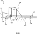
Fig.3 provides a cutaway view of the cradle shown inFig.2 , -
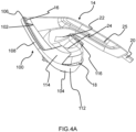
Figs.4A and4B respectively provide exterior and interior views of an iron head docked on the cradle shown inFigs.2 and3 , -
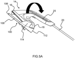
Figs.5A and5B depict tilting of an iron head docked on a cradle, -
Fig.6 depicts an iron head docked on a cradle that does not include rear protruding portion(s) that protrude(s) further in height from a resting platform of the cradle than front protruding portion(s), and hence is not according to the invention as defined in claim 1 of the appended set of claims, -
Fig.7 depicts an iron head according to the invention docked on a cradle that includes rear protruding portion(s) that protrude(s) further in height from a resting platform of the cradle than front protruding portion(s), -
Fig.8 provides a perspective view of part of the iron head and cradle shown inFig.6 , and -
Fig.9 provides a perspective view of part of the iron head and cradle shown inFig.7 . -
Fig.1 depicts asteaming device 10 according to an example. The steamingdevice 10 comprises aniron head 14. - In some embodiments, such as that shown in
Fig. 1 , the steamingdevice 10 comprises abase unit 12 comprising a water tank, and ahose cord 20 for connecting theiron head 14 to thebase unit 12. The water tank stores water used to generate steam. To this end, the steamingdevice 10 further comprises a steam generator to which the water stored in the water tank is supplied. - Referring to
Figs. 1 and4 , theiron head 14 comprises asoleplate 16 for treating garments. Steam is releasable to a garment being treated using the steamingdevice 10 via at least one steam vent delimited by thesoleplate 16. - In some embodiments, such as that shown in
Figs.4A and4B , thesoleplate 16 tapers from at or proximal to a broader rear end of thesoleplate 16 to a sharper front end of thesoleplate 16. Such a broader rear end of thesoleplate 16 can be proximal to, or in some examples included in, arear surface 18 of theiron head 14. - In at least some embodiments, the
iron head 14 comprises acasing 22. Such acasing 22 can be made of any suitable material, such as a plastic material, e.g. an engineering thermoplastic. - As shown in
Figs.4A and4B , anupper surface 24 of thecasing 22 faces away from thesoleplate 16. - Preferably, the
iron head 14 includes ahandle 25 that, when grasped by the user, enables theiron head 14 to be held by the user and moved over a garment. - In some embodiments, such as that shown in
Figs.4A and4B , thehose cord 20 connects to thehandle 25 of theiron head 14. In such embodiments, thehose cord 20 can connect to, and rearwardly extend away from, thehandle 25. In alternative embodiments (not shown in the Figures), thehose cord 20 can connect to, and rearwardly extend away from, a portion of thecasing 22 other than thehandle 25. - More generally, the
hose cord 20 preferably extends rearwardly away from therear surface 18 of theiron head 14. This can assist to minimize the risk of thehose cord 20 impeding movement of theiron head 14, in particular when theiron head 14 is being moved over a garment. - In some embodiments, the steam generator is included in the
base unit 12, and the steam generated by the steam generator is supplied to theiron head 14 via thehose cord 20. - In such embodiments, the
iron head 14 preferably includes asteam heater 27 arranged to re-heat steam and/or water received from the steam generator, prior to the steam exiting theiron head 14 via the at least one steam vent. Thesteam heater 27 may assist to minimise the risk of spitting of water onto the garment being treated. - In alternative embodiments, the
iron head 14 can comprise a steam chamber arranged to generate steam from water supplied, e.g. pumped, thereto from the water tank included in thebase unit 12. - In some embodiments, such as that shown in
Fig.1 , the steamingdevice 10 comprises apole assembly 26. Such apole assembly 26 can support anironing board 28. - Thus, the steaming
device 10 shown inFig.1 can be regarded as a stand steamer. - The
pole assembly 26 is preferably atelescopic pole assembly 26. In such embodiments, height adjustment of the ironingboard 28 can be implemented by extending and collapsing thetelescopic pole assembly 26. - Alternatively or additionally, the ironing
board 28 is preferably tiltable between a vertical orientation and a horizontal orientation, with the latter being shown inFig.1 . The vertical orientation can be used for steaming hanging garments, and the horizontal orientation can be used for ironing. - In some embodiments, such as that shown in
Fig. 1 , the steamingdevice 10 includes asupport base 30 arranged to support thebase unit 12 and/or thepole assembly 26. - The present disclosure more generally relates to a
cradle 100 for docking theiron head 14. Such acradle 100 can be included in the steamingdevice 10, as illustrated inFig. 1 . Thus, the user can be supplied with thecradle 100 along with theiron head 14. - The
iron head 14 can be docked on, in other words supported by, thecradle 100 while theiron head 14 is not being held by the user, in other words during a non-active steaming period. - In some embodiments, such as that shown in
Fig.1 , thecradle 100 is attachable to theironing board 28 and/or to thepole assembly 26 via asupport arm 101 that extends between thecradle 100 and the ironingboard 28 or, as the case may be, thepole assembly 26. - Referring to
Figs.2 to 4B , thecradle 100 comprises aresting platform 102 for supporting thesoleplate 16 of theiron head 14 thereon. Theresting platform 102 comprises arear end 104 and afront end 106. Therear end 104 opposes thefront end 106. - In some embodiments, such as shown in
Figs.2 to 4B , a width of theresting platform 102 tapers from at or proximal to therear end 104 to thefront end 106. Such tapering of theresting platform 102 can mean that theresting platform 102 is wider proximal to therear end 104 and narrower proximal to thefront end 106. - This
tapering resting platform 102 can correspond to the tapering shape of thesoleplate 16 of theiron head 14. In this way, the shape of theresting platform 102 can provide an intuitive guide for how theiron head 14 should be orientated in order to be docked on thecradle 100. - In some embodiments, such as shown in
Figs.2 to 4B , first and secondlateral edges resting platform 102 each extend between therear end 104 and thefront end 106. - The
cradle 100 includes aback support member 112 for therear surface 18 of theiron head 14 to rest thereagainst. Theback support member 112 projects from therear end 104 of theresting platform 102. - In some embodiments, and as best shown in
Fig.4B , therear surface 18 of theiron head 14 includes a rear-facing surface of thecasing 22. In such embodiments, thecasing 22 backwardly protrudes further than the rear end of thesoleplate 16, such that thecasing 22, rather than thesoleplate 16, contacts theback support member 112 when theiron head 14 is docked on thecradle 100. - Such a design can assist to protect the
back support member 112 from the heat of thesoleplate 16, due to the rear end of thesoleplate 16 being prevented by the backwardly protruding casing 22 from contacting theback support member 112 when theiron head 14 is docked on thecradle 100. - With continued reference to
Figs.2 to 4B , a firstlateral support member 114 projects from a left side of theresting platform 102, and a secondlateral support member 116 projects from a right side of theresting platform 102. - As best shown in
Fig.2 , an upper part of the firstlateral support member 114 and an upper part of the secondlateral support member 116 extend towards each other, over the restingplatform 102, to define, together with theback support member 112, a confinedrear region 118 of thecradle 100 for accommodating a rear part of theiron head 14. - For example, the rear part of the
iron head 14 accommodated by the confinedrear region 118 of thecradle 100 includes a rearward portion of thecasing 22 and a rearward portion of thesoleplate 16, e.g. that terminates at the broader rear end of thesoleplate 16. - It is noted that the rear part of the
iron head 14 is distinguished from therear surface 18 of theiron head 14 due to therear surface 18 of theiron head 14 being the surface of theiron head 14 that rests against theback support member 112 of thecradle 100, and the rear part of theiron head 14 being the part of theiron head 14 that resides in the confinedrear region 118 of thecradle 100 defined by theback support member 112 together with the upper parts of the first and secondlateral support members platform 102. - In some embodiments, such as shown in
Figs.2 to 4B , the firstlateral support member 114 projects from the firstlateral edge 108 proximal to therear end 104 of theresting platform 102, and the secondlateral support member 116 projects from the secondlateral edge 110 proximal to therear end 104 of theresting platform 102. - In some embodiments, and as best shown in
Fig.3 , the firstlateral support member 114 and the secondlateral support member 116 each project further in height from theresting platform 102 than theback support member 112. Such a design can balance the requirement for theiron head 14 to be securely dockable on thecradle 100 with avoiding that too much material, e.g. plastic material, is used to fabricate thecradle 100. - Referring to
Figs.5A and5B , there can be tendency for theiron head 14 to tilt backwardly, for example due to the weight of thehose cord 20. A moment generated by the weight of thehose cord 20, noting that thehose cord 20 can have a length that is equal to or greater than 1 meter, can be more than the weight of theiron head 14, leading to backward tilting (illustrated by a curved arrow) of theiron head 14 when docked on thecradle 100. - Due to the upper parts of the first and second
lateral support members resting platform 102, to define the confinedrear region 118, the backwards tilting of theiron head 14 can be restricted by the first and secondlateral support members lateral support members upper surface 24 of thecasing 22 contacting the first and secondlateral support members - Such tilting, even when restricted by the first and second
lateral support members soleplate 16 is exposed to a degree that creates a potential safety concern due to the possibility of the user accidentally touching the thus exposedsoleplate 16. - Referring again to
Figs.2 and4B , thecradle 100 accordingly includes at least onerear protruding portion resting platform 102 into the confinedrear region 118, in other words proximal to therear end 104 of theresting platform 102, and at least onefront protruding portion 124 protruding from theresting platform 102 proximal to thefront end 106, with the at least onerear protruding portion resting platform 102 than the at least onefront protruding portion 124. - The, e.g. each of the, at least one
rear protruding portion resting platform 102 than the front protruding portion(s) 124 can raise the rearward portion of thesoleplate 16 relative to a front portion of thesoleplate 16 when theiron head 14 is docked on thecradle 100. - The thus created moment can serve to limit the spacing between the front end of the
soleplate 16 and theresting platform 102. - The risk of the user accidentally contacting the
soleplate 16 due to thesoleplate 16 being exposed by tilting of theiron head 14 docked on thecradle 100 is correspondingly reduced. - Moreover, by the
cradle 100 comprising front and rear protrudingportions resting platform 102 proximal to thefront end 106 and proximal to therear end 104 of theresting platform 102, thesoleplate 16 is elevated relative to theresting platform 102 proximal to both the front andrear ends resting platform 102, as best shown inFig.4B . - In this way, direct contact between the
soleplate 16 and theresting platform 102 can be minimized or prevented, and hence theresting platform 102 need not itself be made from material capable of withstanding the high temperature of thesoleplate 16. A lower cost material can therefore be used for theresting platform 102 itself. - Referring to
Figs.6 to 9 , the rear protruding portion(s) 120, 122 protruding further in height from theresting platform 102 than the front protruding portion(s) 124 can reduce a minimum distance D1 across a gap between theupper surface 24 of thecasing 22 and each of the firstlateral support member 114 and the secondlateral support member 116 when theiron head 14 is docked on thecradle 100 with all of the front and rear protrudingportions soleplate 16. - It is noted, for the avoidance of doubt, that
Figs.6 to 9 illustrate theiron head 14 when thesoleplate 16 is in full contact with all of the front and rear protrudingportions resting platform 102, in other words before a possible backward tilting of theiron head 14. - In this connection, the minimum distance D1 across the gap is larger in the case of the
cradle 100 shown inFigs.6 and8 , which does not include rear protruding portion(s) 120, 122 protruding further in height from theresting platform 102 than front protruding portion(s) 124, than in the case of thecradle 100 shown inFigs.7 and9 . This is due to the latter including the rear protruding portion(s) 120, 122 protruding further in height from theresting platform 102 than front protruding portion(s) 124. - Preferably, a minimum distance D1 across the gap is in the range of [1; 4] mm. Such a minimum distance D1 can provide a balance between constraining tilting of the docked
iron head 14 with ensuring that docking of theiron head 14 on thecradle 100 is sufficiently easy for the user to implement. - It is reiterated that backwards tilting of the
iron head 14 docked on thecradle 100 can be restricted, e.g. stopped, by the first and secondlateral support members iron head 14 relative to theresting platform 102 is constrained to less than 3 degrees, preferably to less than 2 degrees. This can assist to reduce the risk of the user accidentally contacting thesoleplate 16 due to thesoleplate 16 being exposed by tilting of theiron head 14 docked on thecradle 100. - Such a maximum tilt angle can be directly and positively verified by measuring the angle between the respective planes of the surface of the resting platform 102 (from which surface the front and rear protruding
portions soleplate 16 when the dockediron head 14, with therear surface 18 against theback support member 112 and thesoleplate 16 being in contact with each of the rear protruding portion(s) 120, 122, is backwardly tilted so that theupper surface 24 of thecasing 22 contacts one or both of the first and secondlateral support members - In some embodiments, and referring to
Fig.3 , a height difference HD measured between a highest point of the at least onerear protruding portion front protruding portion 124 is in the range [1; 3] mm. - A height difference HD larger than 3 mm can compromise ease of fitting of the
iron head 14 onto thecradle 100, while ensuring that the height difference HD is equal to or greater than 1 mm can assist to avoid excessive backwards tilting of theiron head 14 docked on thecradle 100. - In some embodiments, such as shown in
Fig.2 , the at least onerear protruding portion rear protruding portion 120 protruding into the confinedregion 118 proximal to the left side, and a secondrear protruding portion 122 protruding into the confinedregion 118 proximal to the right side. The first and second rear protrudingportions iron head 14 relative to theresting platform 102 at each side of thecradle 100. - In some embodiments, a central longitudinal axis LA extends between the
rear end 104 and thefront end 106 and bisects theresting platform 102, with the firstrear protruding portion 120 and the secondrear protruding portion 122 being symmetrically arranged on respective sides of the central longitudinal axis LA. This can assist to ensure that theiron head 14 is balanced when docked on thecradle 100. - In some embodiments, and still referring to
Fig.2 , the, e.g. each of the, at least onerear protruding portion ramp 126; 128 that inclines upwardly towards therear end 104 of theresting platform 102 to a highest point of the at least onerear protruding portion ramp 126; 128 can assist the user to guide theiron head 14 onto thecradle 100, and in particular can help the user to locate therear surface 18 of theiron head 14 against theback support member 112. - For example, the
ramp 126; 128, e.g. in the form of one or more rails, inclines smoothly backwards towards therear end 104 of theresting platform 102. - In embodiments in which the at least one
rear protruding portion rear protruding portion 120 and the secondrear protruding portion 122, the firstrear protruding portion 120 can include afirst ramp 126 that inclines upwardly towards therear end 104 of theresting platform 102 to a highest point of the firstrear protruding portion 120, with the secondrear protruding portion 122 including asecond ramp 128 that inclines upwardly towards therear end 104 of theresting platform 102 to a highest point of the secondrear protruding portion 122. - In some embodiments, such as shown in
Fig.2 , the, e.g. each of the, at least onefront protruding portion 124 is centrally positioned between the left side and the right side of theresting platform 102. For example, the, e.g. each of the, at least onefront protruding portion 124 is positioned along the longitudinal axis LA. - Such central positioning of the front protruding portion(s) 124 can assist in balancing the
iron head 14 when docked on thecradle 100. - In at least some embodiments, the at least one
rear protruding portion front protruding portion 124 comprises a heat resistant material arranged to make contact with thesoleplate 16. In other words, at least the highest point of the rear protruding portion(s) 120, 122 and/or the front protruding portion(s) is made of such a heat resistant material. - Any suitable heat resistant material can be used, for example a heat resistant elastomeric material, e.g. silicone rubber. Such a heat resistant elastomeric material can assist to minimize the risk of the
soleplate 16 being scratched when theiron head 14 is being docked on thecradle 100. - At this point it is noted that the
cradle 100, e.g. parts of thecradle 100 other than the rear and front protrudingportions - The first and second
lateral support members iron head 14 can risk damage to, e.g. scratching of, theupper surface 24 of thecasing 22, particularly when theupper surface 24 makes contact with relatively sharp edges of the first and secondlateral support members iron head 14 on thecradle 100 and removes theiron head 14 from thecradle 100. Alternatively or additionally, such a curving shape of the first and secondlateral support members upper surface 24 of thecasing 22 so that theiron head 14 is a snug fit into thecradle 100. - Accordingly in some embodiments, such as shown in
Figs.2 to 9 , the firstlateral support member 114 and the secondlateral support member 116 curvedly extend over the restingplatform 102 towards each other. This curving of the first and secondlateral support members upper surface 24 of thecasing 22 by the first and secondlateral support members - In such embodiments, a surface of the first
lateral support member 114 that faces theresting platform 102 preferably curves, e.g. together with the firstlateral support member 114 as a whole, over the restingplatform 102 and towards the secondlateral support member 116, with a surface of the secondlateral support member 116 that faces theresting platform 102 curving, e.g. together with the second lateral support member as a whole, over the restingplatform 102 and towards the firstlateral support member 114. - The above embodiments as described are only illustrative, and not intended to limit the technique approaches of the present invention. Although the present invention is described in details referring to the preferable embodiments, those skilled in the art will understand that the technique approaches of the present invention can be modified or equally displaced without departing from the protective scope of the claims of the present invention. In the claims, the word "comprising" does not exclude other elements or steps, and the indefinite article "a" or "an" does not exclude a plurality. Any reference signs in the claims should not be construed as limiting the scope.
Claims (15)
- A cradle (100) for docking an iron head (14), the iron head having a soleplate (16) for treating garments, the cradle comprising:- a resting platform (102) for supporting the soleplate thereon, the resting platform comprising a rear end (104) and a front end (106),- a back support member (112) for a rear surface (18) of the iron head to rest thereagainst, the back support member projecting from the rear end of the resting platform,- a first lateral support member (114) projecting from a left side of the resting platform,- a second lateral support member (116) projecting from a right side of the resting platform, an upper part of the first lateral support member and an upper part of the second lateral support member extending towards each other to define, together with the back support member, a confined rear region (118) of the cradle for accommodating a rear part of the iron head,- at least one rear protruding portion (120, 122) protruding from the resting platform into the confined rear region, and- at least one front protruding portion (124) protruding from the resting platform proximal to the front end, wherein the at least one rear protruding portion protrudes further in height from the resting platform than the at least one front protruding portion.
- The cradle (100) according to claim 1, wherein the at least one rear protruding portion (120, 122) comprises a first rear protruding portion (120) protruding into the confined region (118) proximal to the left side, and a second rear protruding portion (122) protruding into the confined region proximal to the right side.
- The cradle (100) according to claim 2, wherein a central longitudinal axis (LA) extends between the rear end (104) and the front end (106) and bisects the resting platform (102), wherein the first rear protruding portion (120) and the second rear protruding portion (122) are symmetrically arranged on respective sides of the central longitudinal axis.
- The cradle (100) according to any one of claims 1 to 3, wherein the at least one rear protruding portion (120, 122) comprises a ramp (126; 128) that inclines upwardly towards the rear end (104) of the resting platform (102) to a highest point of the at least one rear protruding portion.
- The cradle (100) according to any one of claims 1 to 4, wherein the at least one front protruding portion (124) is centrally positioned between the left side and the right side.
- The cradle (100) according to any one of claims 1 to 5, wherein the at least one rear protruding portion (120, 122) and/or the at least one front protruding portion (124) comprises a heat resistant material arranged to make contact with the soleplate (16).
- The cradle (100) according to any one of claims 1 to 6, wherein the first lateral support member (114) and the second lateral support member (116) curvedly extend over the resting platform (102) towards each other.
- The cradle (100) according to any one of claims 1 to 7, wherein a height difference (HD) measured between a highest point of the at least one rear protruding portion (120, 122) and a highest point of the at least one front protruding portion (124) is in the range [1; 3] mm.
- The cradle (100) according to any one of claims 1 to 8, wherein the first lateral support member (114) and the second lateral support member (116) each project further in height from the resting platform (102) than the back support member (112).
- The cradle (100) according to any one of claims 1 to 9, wherein:- first and second lateral edges (108, 110) of the resting platform (102) each extend between the rear end (104) and the front end (106) of the resting platform,- the first lateral support member (114) projects from the first lateral edge (108) proximal to the rear end, and- the second lateral support member (116) projects from the second lateral edge (110) proximal to the rear end.
- A steaming device (10) comprising:- an iron head (14) having a soleplate (16), and- the cradle (100) according to any one of claims 1 to 10.
- The steaming device (10) according to claim 11, comprising:- a base unit (12) comprising a water tank, and- a hose cord (20) arranged to extend away from the rear surface (18) of the iron head (14), the hose cord connecting the iron head to the base unit.
- The steaming device (10) according to claim 11 or claim 12, wherein the iron head (14) comprises a casing (22) having an upper surface (24) that faces away from the resting platform (102) when the iron head is supported thereon, a gap being provided between the upper surface and each of the first lateral support member (114) and the second lateral support member (116) when the iron head is docked on the cradle (100) with all of the front and rear protruding portions (120, 122, 124) being in contact with the soleplate (16).
- The steaming device (10) according to claim 13, wherein a minimum distance (D1) across said gap is in the range of [1; 4] mm.
- The steaming device (10) according to any one of claims 11 to 14, wherein tilting of the iron head (14) relative to the resting platform (102) is constrained to less than 3 degrees.
Priority Applications (5)
| Application Number | Priority Date | Filing Date | Title |
|---|---|---|---|
| EP23151366.4A EP4400644A1 (en) | 2023-01-12 | 2023-01-12 | Cradle for docking an iron head and steaming device comprising the cradle |
| PCT/EP2023/084003 WO2024149517A1 (en) | 2023-01-12 | 2023-12-01 | Cradle for docking an iron head and steaming device comprising the cradle |
| KR1020247030465A KR102904175B1 (en) | 2023-01-12 | 2023-12-01 | A steaming device comprising a cradle and a cradle for docking with an iron head |
| EP23817160.7A EP4460597B1 (en) | 2023-01-12 | 2023-12-01 | Cradle for docking an iron head and steaming device comprising the cradle |
| CN202380023777.7A CN118765341B (en) | 2023-01-12 | 2023-12-01 | Bracket for docking iron head and steam device including the bracket |
Applications Claiming Priority (1)
| Application Number | Priority Date | Filing Date | Title |
|---|---|---|---|
| EP23151366.4A EP4400644A1 (en) | 2023-01-12 | 2023-01-12 | Cradle for docking an iron head and steaming device comprising the cradle |
Publications (1)
| Publication Number | Publication Date |
|---|---|
| EP4400644A1 true EP4400644A1 (en) | 2024-07-17 |
Family
ID=84943903
Family Applications (2)
| Application Number | Title | Priority Date | Filing Date |
|---|---|---|---|
| EP23151366.4A Withdrawn EP4400644A1 (en) | 2023-01-12 | 2023-01-12 | Cradle for docking an iron head and steaming device comprising the cradle |
| EP23817160.7A Active EP4460597B1 (en) | 2023-01-12 | 2023-12-01 | Cradle for docking an iron head and steaming device comprising the cradle |
Family Applications After (1)
| Application Number | Title | Priority Date | Filing Date |
|---|---|---|---|
| EP23817160.7A Active EP4460597B1 (en) | 2023-01-12 | 2023-12-01 | Cradle for docking an iron head and steaming device comprising the cradle |
Country Status (4)
| Country | Link |
|---|---|
| EP (2) | EP4400644A1 (en) |
| KR (1) | KR102904175B1 (en) |
| CN (1) | CN118765341B (en) |
| WO (1) | WO2024149517A1 (en) |
Families Citing this family (1)
| Publication number | Priority date | Publication date | Assignee | Title |
|---|---|---|---|---|
| EP4653977A1 (en) | 2024-05-24 | 2025-11-26 | LG Electronics Inc. | Knob assembly and cooking apparatus having same |
Citations (5)
| Publication number | Priority date | Publication date | Assignee | Title |
|---|---|---|---|---|
| EP2450486A1 (en) * | 2010-11-05 | 2012-05-09 | Seb S.A. | Charging station for a cordless iron |
| US20190376229A1 (en) * | 2018-06-12 | 2019-12-12 | Seb S.A. | Apparatus for steam treatment of laundry comprising a support device |
| WO2020053909A1 (en) * | 2018-09-14 | 2020-03-19 | De' Longhi Appliances S.R.L. Con Unico Socio | Support base for an iron |
| EP3696314A1 (en) * | 2019-02-12 | 2020-08-19 | Seb S.A. | Device for treating laundry with steam comprising a support device |
| WO2021254930A1 (en) * | 2020-06-19 | 2021-12-23 | Koninklijke Philips N.V. | A garment steamer with docking assembly |
Family Cites Families (3)
| Publication number | Priority date | Publication date | Assignee | Title |
|---|---|---|---|---|
| JP5408121B2 (en) * | 2010-12-27 | 2014-02-05 | 東芝ホームテクノ株式会社 | Ironing equipment |
| FR3092593B1 (en) * | 2019-02-12 | 2021-04-09 | Seb Sa | STEAMING LAUNDRY TREATMENT APPARATUS INCLUDING A SUPPORT DEVICE |
| JP2021194262A (en) * | 2020-06-15 | 2021-12-27 | 東芝ホームテクノ株式会社 | Steam ejection device mounting stage |
-
2023
- 2023-01-12 EP EP23151366.4A patent/EP4400644A1/en not_active Withdrawn
- 2023-12-01 KR KR1020247030465A patent/KR102904175B1/en active Active
- 2023-12-01 WO PCT/EP2023/084003 patent/WO2024149517A1/en not_active Ceased
- 2023-12-01 CN CN202380023777.7A patent/CN118765341B/en active Active
- 2023-12-01 EP EP23817160.7A patent/EP4460597B1/en active Active
Patent Citations (5)
| Publication number | Priority date | Publication date | Assignee | Title |
|---|---|---|---|---|
| EP2450486A1 (en) * | 2010-11-05 | 2012-05-09 | Seb S.A. | Charging station for a cordless iron |
| US20190376229A1 (en) * | 2018-06-12 | 2019-12-12 | Seb S.A. | Apparatus for steam treatment of laundry comprising a support device |
| WO2020053909A1 (en) * | 2018-09-14 | 2020-03-19 | De' Longhi Appliances S.R.L. Con Unico Socio | Support base for an iron |
| EP3696314A1 (en) * | 2019-02-12 | 2020-08-19 | Seb S.A. | Device for treating laundry with steam comprising a support device |
| WO2021254930A1 (en) * | 2020-06-19 | 2021-12-23 | Koninklijke Philips N.V. | A garment steamer with docking assembly |
Also Published As
| Publication number | Publication date |
|---|---|
| EP4460597A1 (en) | 2024-11-13 |
| KR102904175B1 (en) | 2025-12-26 |
| CN118765341B (en) | 2025-08-26 |
| WO2024149517A1 (en) | 2024-07-18 |
| KR20240145028A (en) | 2024-10-04 |
| CN118765341A (en) | 2024-10-11 |
| EP4460597B1 (en) | 2025-05-14 |
Similar Documents
| Publication | Publication Date | Title |
|---|---|---|
| EP4460597B1 (en) | Cradle for docking an iron head and steaming device comprising the cradle | |
| EP3262922B1 (en) | Wearable blower and assembly | |
| KR102533997B1 (en) | Ironing appliance including an iron including a bottom portion and a handle cantilevered relative to the bottom portion | |
| CN105798851B (en) | Components and hand-held work implements with hand-held work implements and support equipment | |
| CN113163997B (en) | Storage docking station for battery powered vacuum cleaner | |
| TW201731441A (en) | Vacuum cleaner | |
| CN211872368U (en) | Apparatus for steam treating laundry | |
| EP4424901A1 (en) | Accessory and garment steamer comprising the same | |
| AU2016336279B2 (en) | Assistance device | |
| JP6815332B2 (en) | Ironing appliances with iron and base including storage for ironing | |
| EP4573241B1 (en) | Telescopic pole assembly for supporting an ironing board | |
| EP4647545A1 (en) | Stand steamer comprising support base and detachable water tank | |
| JP2009028384A (en) | Cordless iron | |
| CN111110527B (en) | Paraplegic walker | |
| JPH0436722Y2 (en) | ||
| WO2026017541A1 (en) | Steaming device with moveable dock for supporting a steamer head | |
| JP4256451B2 (en) | Image forming apparatus | |
| KR960000024Y1 (en) | iron | |
| JP4007109B2 (en) | Cordless iron | |
| EP4177393A1 (en) | Garment steamer comprising a pivotable steamer head | |
| JP2024074275A (en) | Vacuum cleaner nozzle provided with pivot-blocking device | |
| KR20250038706A (en) | Garment steamer with detachable docking unit | |
| EP1421235A1 (en) | Improved ironing board | |
| JP2005224273A (en) | Clothing press equipment | |
| PL7037S2 (en) | Iron |
Legal Events
| Date | Code | Title | Description |
|---|---|---|---|
| PUAI | Public reference made under article 153(3) epc to a published international application that has entered the european phase |
Free format text: ORIGINAL CODE: 0009012 |
|
| STAA | Information on the status of an ep patent application or granted ep patent |
Free format text: STATUS: THE APPLICATION HAS BEEN PUBLISHED |
|
| AK | Designated contracting states |
Kind code of ref document: A1 Designated state(s): AL AT BE BG CH CY CZ DE DK EE ES FI FR GB GR HR HU IE IS IT LI LT LU LV MC ME MK MT NL NO PL PT RO RS SE SI SK SM TR |
|
| STAA | Information on the status of an ep patent application or granted ep patent |
Free format text: STATUS: THE APPLICATION IS DEEMED TO BE WITHDRAWN |
|
| 18D | Application deemed to be withdrawn |
Effective date: 20250118 |