EP4400488A1 - Gas separation method - Google Patents
Gas separation method Download PDFInfo
- Publication number
- EP4400488A1 EP4400488A1 EP22869683.7A EP22869683A EP4400488A1 EP 4400488 A1 EP4400488 A1 EP 4400488A1 EP 22869683 A EP22869683 A EP 22869683A EP 4400488 A1 EP4400488 A1 EP 4400488A1
- Authority
- EP
- European Patent Office
- Prior art keywords
- gas
- desorbed
- target
- adsorption
- component
- Prior art date
- Legal status (The legal status is an assumption and is not a legal conclusion. Google has not performed a legal analysis and makes no representation as to the accuracy of the status listed.)
- Pending
Links
- 238000000926 separation method Methods 0.000 title claims abstract description 46
- 238000000034 method Methods 0.000 claims abstract description 142
- 238000001179 sorption measurement Methods 0.000 claims abstract description 72
- 239000003463 adsorbent Substances 0.000 claims abstract description 70
- 238000003795 desorption Methods 0.000 claims abstract description 40
- 239000007789 gas Substances 0.000 claims description 417
- CURLTUGMZLYLDI-UHFFFAOYSA-N Carbon dioxide Chemical compound O=C=O CURLTUGMZLYLDI-UHFFFAOYSA-N 0.000 claims description 78
- 229910002092 carbon dioxide Inorganic materials 0.000 claims description 72
- 239000001569 carbon dioxide Substances 0.000 claims description 71
- OKKJLVBELUTLKV-UHFFFAOYSA-N Methanol Chemical compound OC OKKJLVBELUTLKV-UHFFFAOYSA-N 0.000 claims description 56
- VNWKTOKETHGBQD-UHFFFAOYSA-N methane Chemical compound C VNWKTOKETHGBQD-UHFFFAOYSA-N 0.000 claims description 44
- UGFAIRIUMAVXCW-UHFFFAOYSA-N Carbon monoxide Chemical compound [O+]#[C-] UGFAIRIUMAVXCW-UHFFFAOYSA-N 0.000 claims description 41
- 229910002091 carbon monoxide Inorganic materials 0.000 claims description 41
- 238000003786 synthesis reaction Methods 0.000 claims description 24
- 230000015572 biosynthetic process Effects 0.000 claims description 23
- 238000006243 chemical reaction Methods 0.000 claims description 19
- 238000006477 desulfuration reaction Methods 0.000 claims description 14
- 230000023556 desulfurization Effects 0.000 claims description 14
- 238000011144 upstream manufacturing Methods 0.000 claims description 14
- XLYOFNOQVPJJNP-UHFFFAOYSA-N water Substances O XLYOFNOQVPJJNP-UHFFFAOYSA-N 0.000 claims description 14
- NINIDFKCEFEMDL-UHFFFAOYSA-N Sulfur Chemical compound [S] NINIDFKCEFEMDL-UHFFFAOYSA-N 0.000 claims description 8
- 239000003638 chemical reducing agent Substances 0.000 claims description 8
- 229910052717 sulfur Inorganic materials 0.000 claims description 8
- 239000011593 sulfur Substances 0.000 claims description 8
- 238000002156 mixing Methods 0.000 claims description 5
- VUZPPFZMUPKLLV-UHFFFAOYSA-N methane;hydrate Chemical compound C.O VUZPPFZMUPKLLV-UHFFFAOYSA-N 0.000 claims description 3
- 239000003054 catalyst Substances 0.000 description 13
- 239000000203 mixture Substances 0.000 description 12
- 239000012535 impurity Substances 0.000 description 9
- XEEYBQQBJWHFJM-UHFFFAOYSA-N Iron Chemical compound [Fe] XEEYBQQBJWHFJM-UHFFFAOYSA-N 0.000 description 6
- 229910021536 Zeolite Inorganic materials 0.000 description 6
- HNPSIPDUKPIQMN-UHFFFAOYSA-N dioxosilane;oxo(oxoalumanyloxy)alumane Chemical compound O=[Si]=O.O=[Al]O[Al]=O HNPSIPDUKPIQMN-UHFFFAOYSA-N 0.000 description 6
- 238000004519 manufacturing process Methods 0.000 description 6
- 239000010457 zeolite Substances 0.000 description 6
- 230000003197 catalytic effect Effects 0.000 description 5
- 230000015556 catabolic process Effects 0.000 description 4
- 238000006731 degradation reaction Methods 0.000 description 4
- 239000000126 substance Substances 0.000 description 4
- OKTJSMMVPCPJKN-UHFFFAOYSA-N Carbon Chemical compound [C] OKTJSMMVPCPJKN-UHFFFAOYSA-N 0.000 description 3
- 229910052799 carbon Inorganic materials 0.000 description 3
- 230000000694 effects Effects 0.000 description 3
- 239000000446 fuel Substances 0.000 description 3
- 229910052742 iron Inorganic materials 0.000 description 3
- 238000001556 precipitation Methods 0.000 description 3
- 239000000047 product Substances 0.000 description 3
- 238000009628 steelmaking Methods 0.000 description 3
- 229910017518 Cu Zn Inorganic materials 0.000 description 2
- 229910017752 Cu-Zn Inorganic materials 0.000 description 2
- 229910017943 Cu—Zn Inorganic materials 0.000 description 2
- 239000006227 byproduct Substances 0.000 description 2
- TVZPLCNGKSPOJA-UHFFFAOYSA-N copper zinc Chemical compound [Cu].[Zn] TVZPLCNGKSPOJA-UHFFFAOYSA-N 0.000 description 2
- 238000010586 diagram Methods 0.000 description 2
- 239000002994 raw material Substances 0.000 description 2
- IJGRMHOSHXDMSA-UHFFFAOYSA-N Atomic nitrogen Chemical compound N#N IJGRMHOSHXDMSA-UHFFFAOYSA-N 0.000 description 1
- 238000010521 absorption reaction Methods 0.000 description 1
- 239000007795 chemical reaction product Substances 0.000 description 1
- 238000010276 construction Methods 0.000 description 1
- 238000001816 cooling Methods 0.000 description 1
- 239000002737 fuel gas Substances 0.000 description 1
- XLYOFNOQVPJJNP-ZSJDYOACSA-N heavy water Substances [2H]O[2H] XLYOFNOQVPJJNP-ZSJDYOACSA-N 0.000 description 1
- 238000009434 installation Methods 0.000 description 1
- 239000007788 liquid Substances 0.000 description 1
- 230000000704 physical effect Effects 0.000 description 1
- 239000012495 reaction gas Substances 0.000 description 1
- 238000004064 recycling Methods 0.000 description 1
- 230000001603 reducing effect Effects 0.000 description 1
- 238000011946 reduction process Methods 0.000 description 1
- 238000002407 reforming Methods 0.000 description 1
- 238000007086 side reaction Methods 0.000 description 1
- 238000002336 sorption--desorption measurement Methods 0.000 description 1
- 238000003860 storage Methods 0.000 description 1
- 230000002194 synthesizing effect Effects 0.000 description 1
- 239000013076 target substance Substances 0.000 description 1
- 238000010792 warming Methods 0.000 description 1
Images

Classifications
-
- B—PERFORMING OPERATIONS; TRANSPORTING
- B01—PHYSICAL OR CHEMICAL PROCESSES OR APPARATUS IN GENERAL
- B01D—SEPARATION
- B01D53/00—Separation of gases or vapours; Recovering vapours of volatile solvents from gases; Chemical or biological purification of waste gases, e.g. engine exhaust gases, smoke, fumes, flue gases, aerosols
- B01D53/34—Chemical or biological purification of waste gases
- B01D53/46—Removing components of defined structure
- B01D53/62—Carbon oxides
-
- B—PERFORMING OPERATIONS; TRANSPORTING
- B01—PHYSICAL OR CHEMICAL PROCESSES OR APPARATUS IN GENERAL
- B01D—SEPARATION
- B01D53/00—Separation of gases or vapours; Recovering vapours of volatile solvents from gases; Chemical or biological purification of waste gases, e.g. engine exhaust gases, smoke, fumes, flue gases, aerosols
- B01D53/02—Separation of gases or vapours; Recovering vapours of volatile solvents from gases; Chemical or biological purification of waste gases, e.g. engine exhaust gases, smoke, fumes, flue gases, aerosols by adsorption, e.g. preparative gas chromatography
- B01D53/04—Separation of gases or vapours; Recovering vapours of volatile solvents from gases; Chemical or biological purification of waste gases, e.g. engine exhaust gases, smoke, fumes, flue gases, aerosols by adsorption, e.g. preparative gas chromatography with stationary adsorbents
-
- B—PERFORMING OPERATIONS; TRANSPORTING
- B01—PHYSICAL OR CHEMICAL PROCESSES OR APPARATUS IN GENERAL
- B01D—SEPARATION
- B01D53/00—Separation of gases or vapours; Recovering vapours of volatile solvents from gases; Chemical or biological purification of waste gases, e.g. engine exhaust gases, smoke, fumes, flue gases, aerosols
- B01D53/02—Separation of gases or vapours; Recovering vapours of volatile solvents from gases; Chemical or biological purification of waste gases, e.g. engine exhaust gases, smoke, fumes, flue gases, aerosols by adsorption, e.g. preparative gas chromatography
- B01D53/04—Separation of gases or vapours; Recovering vapours of volatile solvents from gases; Chemical or biological purification of waste gases, e.g. engine exhaust gases, smoke, fumes, flue gases, aerosols by adsorption, e.g. preparative gas chromatography with stationary adsorbents
- B01D53/047—Pressure swing adsorption
-
- C—CHEMISTRY; METALLURGY
- C07—ORGANIC CHEMISTRY
- C07C—ACYCLIC OR CARBOCYCLIC COMPOUNDS
- C07C1/00—Preparation of hydrocarbons from one or more compounds, none of them being a hydrocarbon
- C07C1/02—Preparation of hydrocarbons from one or more compounds, none of them being a hydrocarbon from oxides of a carbon
- C07C1/04—Preparation of hydrocarbons from one or more compounds, none of them being a hydrocarbon from oxides of a carbon from carbon monoxide with hydrogen
-
- C—CHEMISTRY; METALLURGY
- C07—ORGANIC CHEMISTRY
- C07C—ACYCLIC OR CARBOCYCLIC COMPOUNDS
- C07C1/00—Preparation of hydrocarbons from one or more compounds, none of them being a hydrocarbon
- C07C1/02—Preparation of hydrocarbons from one or more compounds, none of them being a hydrocarbon from oxides of a carbon
- C07C1/12—Preparation of hydrocarbons from one or more compounds, none of them being a hydrocarbon from oxides of a carbon from carbon dioxide with hydrogen
-
- C—CHEMISTRY; METALLURGY
- C07—ORGANIC CHEMISTRY
- C07C—ACYCLIC OR CARBOCYCLIC COMPOUNDS
- C07C29/00—Preparation of compounds having hydroxy or O-metal groups bound to a carbon atom not belonging to a six-membered aromatic ring
- C07C29/15—Preparation of compounds having hydroxy or O-metal groups bound to a carbon atom not belonging to a six-membered aromatic ring by reduction of oxides of carbon exclusively
- C07C29/151—Preparation of compounds having hydroxy or O-metal groups bound to a carbon atom not belonging to a six-membered aromatic ring by reduction of oxides of carbon exclusively with hydrogen or hydrogen-containing gases
-
- C—CHEMISTRY; METALLURGY
- C07—ORGANIC CHEMISTRY
- C07C—ACYCLIC OR CARBOCYCLIC COMPOUNDS
- C07C31/00—Saturated compounds having hydroxy or O-metal groups bound to acyclic carbon atoms
- C07C31/02—Monohydroxylic acyclic alcohols
- C07C31/04—Methanol
-
- C—CHEMISTRY; METALLURGY
- C07—ORGANIC CHEMISTRY
- C07C—ACYCLIC OR CARBOCYCLIC COMPOUNDS
- C07C9/00—Aliphatic saturated hydrocarbons
- C07C9/02—Aliphatic saturated hydrocarbons with one to four carbon atoms
- C07C9/04—Methane
-
- C—CHEMISTRY; METALLURGY
- C22—METALLURGY; FERROUS OR NON-FERROUS ALLOYS; TREATMENT OF ALLOYS OR NON-FERROUS METALS
- C22B—PRODUCTION AND REFINING OF METALS; PRETREATMENT OF RAW MATERIALS
- C22B5/00—General methods of reducing to metals
- C22B5/02—Dry methods smelting of sulfides or formation of mattes
-
- B—PERFORMING OPERATIONS; TRANSPORTING
- B01—PHYSICAL OR CHEMICAL PROCESSES OR APPARATUS IN GENERAL
- B01D—SEPARATION
- B01D2253/00—Adsorbents used in seperation treatment of gases and vapours
- B01D2253/10—Inorganic adsorbents
- B01D2253/106—Silica or silicates
- B01D2253/108—Zeolites
-
- B—PERFORMING OPERATIONS; TRANSPORTING
- B01—PHYSICAL OR CHEMICAL PROCESSES OR APPARATUS IN GENERAL
- B01D—SEPARATION
- B01D2256/00—Main component in the product gas stream after treatment
- B01D2256/20—Carbon monoxide
-
- B—PERFORMING OPERATIONS; TRANSPORTING
- B01—PHYSICAL OR CHEMICAL PROCESSES OR APPARATUS IN GENERAL
- B01D—SEPARATION
- B01D2256/00—Main component in the product gas stream after treatment
- B01D2256/22—Carbon dioxide
-
- B—PERFORMING OPERATIONS; TRANSPORTING
- B01—PHYSICAL OR CHEMICAL PROCESSES OR APPARATUS IN GENERAL
- B01D—SEPARATION
- B01D2257/00—Components to be removed
- B01D2257/50—Carbon oxides
- B01D2257/502—Carbon monoxide
-
- B—PERFORMING OPERATIONS; TRANSPORTING
- B01—PHYSICAL OR CHEMICAL PROCESSES OR APPARATUS IN GENERAL
- B01D—SEPARATION
- B01D2257/00—Components to be removed
- B01D2257/50—Carbon oxides
- B01D2257/504—Carbon dioxide
-
- B—PERFORMING OPERATIONS; TRANSPORTING
- B01—PHYSICAL OR CHEMICAL PROCESSES OR APPARATUS IN GENERAL
- B01D—SEPARATION
- B01D2258/00—Sources of waste gases
- B01D2258/02—Other waste gases
- B01D2258/025—Other waste gases from metallurgy plants
-
- Y—GENERAL TAGGING OF NEW TECHNOLOGICAL DEVELOPMENTS; GENERAL TAGGING OF CROSS-SECTIONAL TECHNOLOGIES SPANNING OVER SEVERAL SECTIONS OF THE IPC; TECHNICAL SUBJECTS COVERED BY FORMER USPC CROSS-REFERENCE ART COLLECTIONS [XRACs] AND DIGESTS
- Y02—TECHNOLOGIES OR APPLICATIONS FOR MITIGATION OR ADAPTATION AGAINST CLIMATE CHANGE
- Y02C—CAPTURE, STORAGE, SEQUESTRATION OR DISPOSAL OF GREENHOUSE GASES [GHG]
- Y02C20/00—Capture or disposal of greenhouse gases
- Y02C20/40—Capture or disposal of greenhouse gases of CO2
Definitions
- This disclosure relates to a gas separation method.
- the pressure swing adsorption (PSA) method has been used as a method for separating predetermined gas components contained in a source gas (see, for example, JPH06-144818A (PTL 1)).
- the PSA method is a separation method that utilizes the fact that the amount of a gas component adsorbed on an adsorbent depends on the gas species and partial pressure thereof.
- the PSA method usually includes a process in which a gas component is adsorbed on an adsorbent (adsorption process), a process in which part of a desorbed gas desorbed in another adsorbent vessel is supplied as rinse gas to increase the adsorption ratio of the gas component on the adsorbent (rinse process), and a process in which the adsorbed gas component is desorbed from the adsorbent and recovered (desorption process).
- adsorption process a process in which a gas component is adsorbed on an adsorbent
- rinse process a process in which part of a desorbed gas desorbed in another adsorbent vessel is supplied as rinse gas to increase the adsorption ratio of the gas component on the adsorbent
- desorption process a process in which the adsorbed gas component is desorbed from the adsorbent and recovered
- the PSA method described above which has been applied in various fields, is often used as a method for producing highly concentrated gas by adsorbing a gas component contained in a source gas.
- the PSA method includes a pressurizing type utilizing a difference between increased pressure and normal pressure and a vacuum type utilizing a difference between normal pressure (or slightly increased pressure) and reduced pressure.
- the latter type is also called VSA (vacuum swing adsorption) method.
- CCU carbon dioxide capture and utilization
- JP2018-114464A a gas separation method based on the difference in gas desorption time, utilizing the characteristic that the time taken for gas to desorb from the adsorbent varies depending on the adsorbed gas species.
- This method can efficiently separate CO 2 , which has stronger adsorption affinity, from CO and N 2 , which have weaker adsorption affinity, among blast furnace gas (containing CO 2 , carbon monoxide (CO), and nitrogen (N 2 )) emitted from, for example, a steelmaking process.
- the CO 2 to be separated is precisely a gas (CO 2 -rich gas) that also contains some impurity gases such as CO and N 2 , but hereinafter referred to as CO 2 for the sake of simplicity of explanation.
- the simple gas separation method described in PTL 2 can be used to reduce the production cost of CCU chemicals.
- the gas separated by the method described in PTL 2 may be separated as a gas containing many impurities depending on the operation method. This may affect the catalytic performance of the reactor in the CCU process.
- Various catalysts are used in the reactor used for CCU, depending on the intended reaction product.
- the catalytic performance is affected not only by reaction conditions such as temperature and pressure, but also by the composition of the source gas.
- reaction conditions such as temperature and pressure
- high-purity CO 2 is required.
- an impurity gas component that does not affect the catalyst performance can be fed as it is to the reactor, high-purity CO 2 is not necessary.
- CO 2 separation apparatus when the required purity of the source gas CO 2 is different for each catalyst of the reactor, it is necessary to select the appropriate CO 2 separation apparatus depending on CO 2 purity. For example, when high-purity CO 2 is required, a CO 2 separation apparatus that can produce high-purity CO 2 , such as in the chemical absorption method, is suitable. When high-purity CO 2 is not required, CO 2 can be separated simply by using, for example, the PSA method described above.
- the pressure swing adsorption method can separate and supply a suitable gas from the source gas to each of a plurality of gas utilizing apparatuses.
- the gas separation method according to this disclosure which is a gas separation method for adsorbing and separating a target gas component from a source gas containing two or more gas components by a pressure swing adsorption method, includes a target gas component adsorption process in which the source gas is introduced into an adsorbent vessel filled with an adsorbent and the target gas component is adsorbed on the adsorbent, a target gas component desorption process in which the target gas component adsorbed on the adsorbent in the target gas component adsorption process is desorbed to discharge a desorbed gas from the adsorbent vessel, and a desorbed gas supply process in which the desorbed gas discharged from the adsorbent vessel in the target gas component desorption process is supplied to two or more different gas utilizing apparatuses.
- the target gas component desorption process has a desorbed gas utilizing apparatus switching process in which a supply destination of the desorbed gas in the
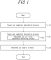
- FIG. 1 illustrates a flowchart of the gas separation method according to this disclosure.
- Step S1 a source gas is introduced into an adsorbent vessel filled with an adsorbent and a target gas component is adsorbed on the adsorbent (target gas component adsorption process).
- the source gas is not limited as long as it contains two or more gas components, but it should contain at least CO 2 and CO. While CO 2 and CO can contribute to global warming if released into the air, they can be effectively used as raw materials for synthesizing fuels such as methane and methanol, and as reducing agents in a reduction furnace. CO can also be used as a fuel gas because of its high heat quantity. Therefore, the source gas should contain at least CO 2 and CO.
- a by-product gas generated at steelworks can be used.
- the by-product gas exhaust gas emitted from a reduction furnace such as a blast furnace and shaft furnace can be used.
- blast furnace gas emitted from a blast furnace contains not only CO 2 richly, but also contain CO.
- the source gas contains CO, there are concerns about catalyst degradation due to carbon precipitation caused by CO, depending on the catalyst used by the gas utilizing apparatuses supplied in the desorbed gas supply process described below.
- the CO content of the desorbed gas supplied to such apparatuses can be controlled, so a blast furnace gas can be used as the source gas without problems.
- the source gas as described above is introduced into an adsorbent vessel filled with an adsorbent and a target gas component is adsorbed on the adsorbent.
- the adsorbent filled in the adsorbent vessel can be appropriately selected depending on the target gas component to be adsorbed on the adsorbent.
- the target gas component is not limited and can be, for example, CO 2 or CO. When the target gas component is CO 2 , 13X zeolite or the like can be suitably used as the adsorbent.
- Step S2 the target gas component adsorbed on the adsorbent in Step S 1 is desorbed to discharge a desorbed gas containing the target gas component from the adsorbent vessel (target gas component desorption process).
- Desorption of the target gas component from the adsorbent and discharge from the adsorbent vessel can be performed by connecting a vacuum pump to the adsorbent vessel.
- the desorption process is divided into multiple time periods and the desorbed gas is discharged separately for each time period.
- 13X zeolite used as an adsorbent for CO 2 has linear adsorption properties with respect to pressure for gas components with weaker adsorption affinity such as N 2 and CO.
- gas components with stronger adsorption affinity such as CO 2
- it has a large adsorption volume and nonlinear adsorption properties with respect to pressure.
- a gas component with linear adsorption properties with respect to pressure e.g., CO, N 2
- a gas component with nonlinear adsorption properties with respect to pressure is hardly desorbed under high-pressure conditions and rapidly desorbed when the pressure is reduced to low.
- a desorbed gas in the early stage of the desorption process which contains many impurity gas components, is fed to a gas utilizing apparatus that tolerate a source gas containing impurities.
- a desorbed gas in the latter stage of the desorption process which contains few impurity gas components, is fed to another gas utilizing apparatus that requires high-purity source gas.
- the amount of desorbed gas fed to these gas utilizing apparatuses and the concentration of the target gas component in the desorbed gas can be easily adjusted by changing the length of the time period produced by dividing the desorption process.
- Step S21 a supply destination of the desorbed gas in the desorbed gas supply process in Step S3 described below is switched among the gas utilizing apparatuses (desorbed gas utilizing apparatus switching process).
- the switching can be performed at the boundaries of multiple time periods that are produced by dividing the desorption process. This allows the desorbed gas to be fed to an appropriate gas utilizing apparatus based on its composition (concentration of target gas component).
- Step S3 the desorbed gas discharged from the adsorbent vessel in Step S2 is fed to two or more different gas utilizing apparatuses (desorbed gas supply process).
- the desorbed gas is thus fed to an appropriate gas utilizing apparatus based on its composition (concentration of target gas component).
- the "gas utilizing apparatus” means an apparatus such as a reactor, reformer, and condenser that chemically or physically transforms the desorbed or adsorbed off-gas to obtain a target substance.
- the reactor includes a methanol synthesis reactor and methane synthesis reactor.
- the reformer includes a water gas shift reformer and dry reforming apparatus that reacts methane with CO 2 .
- the condenser includes a CO 2 liquefaction apparatus and gas deep-cooling separation apparatus.
- one of the two or more different gas utilizing apparatuses is preferably a methanol synthesis reactor.
- Methanol can be used as a fuel and produced by the reaction of the equation (1) of CO 2 and H 2 or the equation (2) of CO and H 2 .
- Cu-Zn catalysts commonly used in methanol synthesis are less susceptible to degradation of catalytic performance due to carbon precipitation even when a CO-containing source gas is used. Rather, the source gas containing even a small amount of CO has the advantage of improving the yield of the reaction of converting CO 2 to methanol because the side reaction of converting CO 2 to CO is suppressed. Thus, when the gas utilizing apparatus is a methanol synthesis reactor, even a desorbed gas without a high concentration of CO 2 can be used as a source gas for methanol synthesis.
- a desorbed gas obtained in the middle stage of the desorption process when a relatively high concentration of CO is desorbed in the desorption process can be fed to the methanol synthesis reactor and the concentration control of the desorbed gas in this disclosure can be effectively used.
- one of the two or more different gas utilizing apparatuses is preferably a methane synthesis reactor.
- Methane can be used not only as a fuel, but also as a reducing agent for the reduction of oxides in the reduction furnace.
- Methane can be produced by the reaction of the equation (3) of CO 2 and H 2 or the equation (4) of CO and H 2 .
- Ni catalysts used in methane synthesis from CO 2 may suffer from degradation of catalytic performance due to carbon precipitation when a CO-containing source gas is used. Therefore, a desorbed gas obtained in the latter stage of the desorption process when a high concentration of CO 2 is desorbed in the desorption process is fed to the methanol synthesis reactor.
- one of the two or more different gas utilizing apparatuses is preferably a CO 2 liquefaction apparatus.
- the source gas is a mixed gas containing CO 2 and CO and the adsorbent is a zeolite
- most of the gas components that are desorbed in the latter stage of the desorption process are CO 2 that has stronger adsorption affinity on the adsorbent, and thus the desorbed gas is discharged as high-purity CO 2 gas. Therefore, the desorbed gas discharged in the latter stage of the desorption process can be fed to the CO 2 liquefaction apparatus for CO 2 storage (CCS) or other purposes.
- CCS CO 2 storage
- the product of the gas utilizing apparatus can be supplied as a reducing agent in the reduction furnace.
- the product in the gas utilizing apparatus is not limited to the above methanol and is not limited to any particular substance as long as it has a reducibility to raw materials of reduction furnaces such as iron ore.
- the physical properties, such as gas or liquid, are not limited, either.
- the methane produced has a reducing effect on oxides such as iron ore and thus can be used as a reducing agent in the reduction furnace.
- the source gas for the methane synthesis reactor is CO 2
- CO 2 it is possible to establish a carbon-recycling reduction process in which CO 2 is converted to methane and C is recycled.
- the methane synthesis reaction is an exothermic reaction, and by using the high-temperature methane produced as it is as a reducing agent in the reduction furnace, the reaction heat of the methane synthesis can also be effectively utilized.
- the PSA method can separate and supply a suitable gas from the source gas to each of a plurality of gas utilizing apparatuses.
- This disclosure can further comprise, upstream of the desorbed gas supply process, one or both of a desulfurization process in which sulfur is removed from the source gas or desorbed gas, and a water gas shift reaction process in which CO 2 is generated from CO and water (H 2 O) contained in the source gas or desorbed gas.
- a desulfurization process in which sulfur is removed from the source gas or desorbed gas
- a water gas shift reaction process in which CO 2 is generated from CO and water (H 2 O) contained in the source gas or desorbed gas.
- sulfur contained in the desorbed gas is preferably removed in a desulfurization apparatus before the gas is fed to the gas utilizing apparatus (desulfurization process).
- the desulfurization process can be performed or not depending on the performance of the catalyst, etc. used in the gas utilizing apparatus.
- the desulfurization process When the desulfurization process is performed, it may be performed at any stage upstream of the desorbed gas supply process that supplies a desorbed gas to the gas utilizing apparatus.
- the desulfurization process can be performed by installing a desulfurization apparatus upstream of any one of the gas utilizing apparatuses.
- a desulfurization apparatus can be installed upstream of the PSA apparatus to remove sulfur from the source gas, and then feed the source gas after desulfurization to the PSA apparatus so that all gas utilizing apparatuses are supplied with desulfurized desorbed gas.
- the water gas shift reaction process is a process to cause the reaction of CO and H 2 O in the equation (5), and the balance between CO and CO 2 concentrations can be adjusted by the reaction ratio.
- the requirements of the gas utilizing apparatus can be satisfied by performing the water gas shift reaction process as a pretreatment process of the desorbed gas supply process.
- Both the desulfurization process and water gas shift reaction process can be performed as appropriate according to the specifications of the gas utilizing apparatus. Both the desulfurization process and water gas shift reaction process can be performed consecutively upstream of the desorbed gas supply process. In such case, it is preferable to perform the water gas shift reaction process after the desulfurization process. By performing the processes in this order, sulfur in the gas is removed before the gas is fed to the apparatus where the water gas shift reaction takes place. This is more desirable because the catalyst in the apparatus where the water gas shift reaction process is performed will not be in contact with sulfur, which slows the catalyst degradation rate.
- a gas mixing process in which the desorbed gases with different concentrations of the target gas component discharged from the adsorbent vessel are mixed.
- a tank or other gas mixing apparatus upstream of the gas utilizing apparatus to collect and thoroughly mix the desorbed gas discharged during a given period to equalize the composition of the desorbed gas and reduce the effects of composition fluctuations before supplying the desorbed gas to the gas utilizing apparatus. This can reduce the effect on the production efficiency of the gas utilizing apparatus.
- the gas supplied to the gas utilizing apparatus is the desorbed gas obtained in the target gas component desorption process.
- an adsorption off-gas containing a non-adsorbed gas component that was not adsorbed by the adsorbent in the target gas component adsorption process can be fed to the gas utilizing apparatus (adsorption off-gas supply process).
- gas utilizing apparatus when the gas utilizing apparatus has a large allowable amount of impurity gas (e.g., CO) other than the main reaction gas (e.g., CO 2 ), gas containing a large amount of impurity gas, such as an adsorption off-gas containing a non-adsorbed gas component in the adsorption process of the PSA apparatus, can also be fed and used in the gas utilizing apparatus.
- impurity gas e.g., CO
- main reaction gas e.g., CO 2
- the "non-adsorbed gas component” which simply means a gas component that was not adsorbed on the adsorbent during the adsorption process, does not mean a gas component without adsorption affinity on the adsorbent.
- the source gas contains CO 2 , CO, and H 2 and the adsorbent is a zeolite
- the adsorption affinity on the adsorbent is higher in order of CO 2 , CO, and H 2 . Therefore, H 2 makes up the majority of the adsorption off-gas at the early stage of the adsorption process.
- CO 2 is no longer adsorbed on the adsorbent due to breakthrough.
- Such CO 2 that was not adsorbed on the adsorbent due to breakthrough is also included in the "non-adsorbed gas component".
- a supply destination of the adsorption off-gas is preferably switched among the gas utilizing apparatuses based on a concentration of the target gas component in the adsorption off-gas (adsorption off-gas utilizing apparatus switching process).
- the composition (concentration of target gas component) of the adsorbed off-gas containing a non-adsorbed gas component that was not adsorbed on the adsorbent in the target gas component adsorption process changes with time, as does the adsorbed gas.
- the source gas contains CO 2 , CO, and H 2 and the adsorbent is a zeolite
- the adsorption off-gas in the early stage of the adsorption process is mostly H 2 , and the concentration of CO increases as the adsorption process proceeds.
- an off-gas in the early stage of the adsorption process can be fed to a gas utilizing apparatus that uses H 2 and an off-gas in the middle stage of the adsorption process can be fed to an apparatus that uses CO 2 , thus making it possible to feed the appropriate gas to each of the gas utilizing apparatuses depending on the composition of the adsorption off-gas.
- a blast furnace gas was introduced into a gas separation apparatus and a desorbed gas was fed to the gas utilizing apparatus. Specifically, first, the blast furnace gas discharged from a blast furnace that is a reduction furnace was reformed and cleaned by a pretreatment apparatus. The reformed and cleaned gas was then introduced as a source gas into one of two adsorbent vessels that constitute the gas separation apparatus (PSA apparatus), where a valve V1 in the exhaust line is open and a valve V2 is closed (in the other adsorbent vessel, the valve V1 is closed and V2 is open).
- PSA apparatus gas separation apparatus
- CO 2 contained in the blast furnace gas was adsorbed onto an adsorbent (13X zeolite) filled in the adsorbent vessel (target gas component adsorption process).
- An adsorbed off-gas that was not adsorbed on the adsorbent in the target gas component adsorption process was introduced into a gas tank 1 positioned upstream of a methanol synthesis reactor that uses a Cu-Zn catalyst.
- CO 2 adsorbed on the adsorbent was desorbed by a vacuum pump VP, and the desorbed gas containing CO 2 was discharged from the adsorbent vessel (target gas component desorption process).
- the target gas component desorption process was divided into two time periods according to the changes over time of the composition of the adsorption gas.
- the valve V1 was closed, valve V2 was open, a valve V3 was open, and a valve V4 was closed, and an adsorption gas with a relatively low CO 2 concentration was introduced into the gas tank 1 positioned upstream of the methanol synthesis reactor and mixed with the adsorption off-gas (mixing process).
- valve V3 was closed and valve V4 was open to switch the supply destination of desorbed gas to a methane synthesis reactor, and a desorbed gas with a relatively high CO 2 concentration was introduced into a gas tank 2 positioned upstream of the methane synthesis reactor that uses a Ni catalyst.
- the gases introduced into the gas tank 1 and gas tank 2 were sufficiently mixed, respectively, the gas in the gas tank 1 was fed to the methanol synthesis reactor along with H 2 gas to synthesize methanol.
- the gas in the gas tank 2 was fed to the methane synthesis reactor along with H 2 gas to synthesize methane.
- the synthesized methane was fed to the blast furnace that is a reduction furnace as a reducing agent to reduce oxides contained in iron ores.
- the pressure swing adsorption method which can separate and supply a suitable gas from a source gas to each of a plurality of gas utilizing apparatuses, is useful in steelmaking industry.
Landscapes
- Chemical & Material Sciences (AREA)
- Organic Chemistry (AREA)
- Engineering & Computer Science (AREA)
- Oil, Petroleum & Natural Gas (AREA)
- Chemical Kinetics & Catalysis (AREA)
- General Chemical & Material Sciences (AREA)
- Analytical Chemistry (AREA)
- Environmental & Geological Engineering (AREA)
- Biomedical Technology (AREA)
- Health & Medical Sciences (AREA)
- Manufacturing & Machinery (AREA)
- Materials Engineering (AREA)
- Mechanical Engineering (AREA)
- Metallurgy (AREA)
- Separation Of Gases By Adsorption (AREA)
- Carbon And Carbon Compounds (AREA)
Abstract
Description
- This disclosure relates to a gas separation method.
- Conventionally, the pressure swing adsorption (PSA) method has been used as a method for separating predetermined gas components contained in a source gas (see, for example,
JPH06-144818A - The PSA method described above, which has been applied in various fields, is often used as a method for producing highly concentrated gas by adsorbing a gas component contained in a source gas. The PSA method includes a pressurizing type utilizing a difference between increased pressure and normal pressure and a vacuum type utilizing a difference between normal pressure (or slightly increased pressure) and reduced pressure. The latter type is also called VSA (vacuum swing adsorption) method.
- In recent years, the carbon dioxide capture and utilization (CCU) process, which produces useful chemicals such as methanol from carbon dioxide (CO2) emitted from steelmaking processes, etc., has been studied. Because the reaction process such as CCU can use even a source gas without high purity, the gas separation apparatus can be made inexpensive.
- As a gas separation apparatus suitable for CCU, we proposed, in
JP2018-114464A -
- PTL 1:
JPH06-144818A - PTL 2:
JP2018-114464A - The simple gas separation method described in
PTL 2 can be used to reduce the production cost of CCU chemicals. On the other hand, however, the gas separated by the method described inPTL 2 may be separated as a gas containing many impurities depending on the operation method. This may affect the catalytic performance of the reactor in the CCU process. - Various catalysts are used in the reactor used for CCU, depending on the intended reaction product. The catalytic performance is affected not only by reaction conditions such as temperature and pressure, but also by the composition of the source gas. For example, when a catalyst that is easily deactivated by impurity gas components other than CO2 is used, high-purity CO2 is required. On the other hand, because an impurity gas component that does not affect the catalyst performance can be fed as it is to the reactor, high-purity CO2 is not necessary.
- Thus, when the required purity of the source gas CO2 is different for each catalyst of the reactor, it is necessary to select the appropriate CO2 separation apparatus depending on CO2 purity. For example, when high-purity CO2 is required, a CO2 separation apparatus that can produce high-purity CO2, such as in the chemical absorption method, is suitable. When high-purity CO2 is not required, CO2 can be separated simply by using, for example, the PSA method described above.
- Meanwhile, when different CO2 separation apparatuses are installed in reactors, respectively, in this manner, various disadvantages arise, such as increased construction costs and increased operating personnel due to the installation of multiple apparatuses. In addition, the production volume of each reactor is constrained by the processing capacity of the CO2 separation apparatus, making it impossible to flexibly adjust the production volume balance among the reactors.
- It could thus be helpful to provide a gas separation method that can separate and supply a suitable gas from a source gas to each of a plurality of gas utilizing apparatuses by using the pressure swing adsorption method.
- We thus provide the following.
- [1] A gas separation method for adsorbing and separating a target gas component from a source gas containing two or more gas components by a pressure swing adsorption method, comprising
- a target gas component adsorption process in which the source gas is introduced into an adsorbent vessel filled with an adsorbent and the target gas component is adsorbed on the adsorbent,
- a target gas component desorption process in which the target gas component adsorbed on the adsorbent in the target gas component adsorption process is desorbed to discharge a desorbed gas containing the target gas component from the adsorbent vessel, and
- a desorbed gas supply process in which the desorbed gas discharged from the adsorbent vessel in the target gas component desorption process is supplied to two or more different gas utilizing apparatuses, wherein
- the target gas component desorption process has a desorbed gas utilizing apparatus switching process in which a supply destination of the desorbed gas in the desorbed gas supply process is switched among the gas utilizing apparatuses.
- [2] The gas separation method according to [1], wherein the source gas contains at least carbon dioxide and carbon monoxide.
- [3] The gas separation method according to [1] or [2], wherein the source gas is an exhaust gas discharged from a reduction furnace.
- [4] The gas separation method according to any one of [1] to [3], wherein in the desorbed gas utilizing apparatus switching process, the supply destination is switched among the gas utilizing apparatuses at boundaries of multiple time periods that are produced by dividing the target gas component desorption process.
- [5] The gas separation method according to any one of [1] to [4], further comprising, upstream of the desorbed gas supply process, one or both of a desulfurization process in which sulfur is removed from the source gas or the desorbed gas, and a water gas shift reaction process in which carbon dioxide is generated from the carbon monoxide and water contained in the source gas or the desorbed gas.
- [6] The gas separation method according to any one of [1] to [5], wherein the target gas component adsorption process further has an adsorption off-gas supply process in which an adsorption off-gas containing a non-adsorbed gas component not adsorbed on the adsorbent in the target gas component adsorption process is supplied to one of the two or more different gas utilizing apparatuses.
- [7] The gas separation method according to [6], wherein the target gas component adsorption process has an adsorption off-gas utilizing apparatus switching process for switching a supply destination of the adsorption off-gas among the gas utilizing apparatuses based on a concentration of the target gas component in the adsorption off-gas.
- [8] The gas separation method according to any one of [1] to [7], further comprising, downstream of the target gas component desorption process and upstream of the desorbed gas supply process, a gas mixing process in which the desorbed gases with different concentrations of the target gas component discharged from the adsorbent vessel are mixed.
- [9] The gas separation method according to any one of [1] to [8], wherein one of the two or more gas utilizing apparatuses is a methanol synthesis reactor.
- [10] The gas separation method according to any one of [1] to [9], wherein one of the two or more gas utilizing apparatuses is a methane synthesis reactor.
- [11] The gas separation method according to any one of [1] to [8], wherein one of the two or more gas utilizing apparatuses is a CO2 liquefaction apparatus.
- [12] The gas separation method according to [10] citing [2] or [3], or [11] citing [2] or [3], wherein a product of the gas utilizing apparatuses is supplied as a reducing agent in the reduction furnace.
- According to this disclosure, the pressure swing adsorption method can separate and supply a suitable gas from the source gas to each of a plurality of gas utilizing apparatuses.
- In the accompanying drawings:
-
FIG. 1 illustrates a flowchart of the gas separation method according to this disclosure; and -
FIG. 2 illustrates a flow diagram of the gas separation process in the example. - The following illustrates an embodiment of this disclosure with reference to the drawings. The gas separation method according to this disclosure, which is a gas separation method for adsorbing and separating a target gas component from a source gas containing two or more gas components by a pressure swing adsorption method, includes a target gas component adsorption process in which the source gas is introduced into an adsorbent vessel filled with an adsorbent and the target gas component is adsorbed on the adsorbent, a target gas component desorption process in which the target gas component adsorbed on the adsorbent in the target gas component adsorption process is desorbed to discharge a desorbed gas from the adsorbent vessel, and a desorbed gas supply process in which the desorbed gas discharged from the adsorbent vessel in the target gas component desorption process is supplied to two or more different gas utilizing apparatuses. The target gas component desorption process has a desorbed gas utilizing apparatus switching process in which a supply destination of the desorbed gas in the desorbed gas supply process is switched among the gas utilizing apparatuses.
-
FIG. 1 illustrates a flowchart of the gas separation method according to this disclosure. First, in Step S1, a source gas is introduced into an adsorbent vessel filled with an adsorbent and a target gas component is adsorbed on the adsorbent (target gas component adsorption process). - The source gas is not limited as long as it contains two or more gas components, but it should contain at least CO2 and CO. While CO2 and CO can contribute to global warming if released into the air, they can be effectively used as raw materials for synthesizing fuels such as methane and methanol, and as reducing agents in a reduction furnace. CO can also be used as a fuel gas because of its high heat quantity. Therefore, the source gas should contain at least CO2 and CO.
- As such CO2- and CO-containing source gases, a by-product gas generated at steelworks can be used. As the by-product gas, exhaust gas emitted from a reduction furnace such as a blast furnace and shaft furnace can be used. In particular, blast furnace gas emitted from a blast furnace contains not only CO2 richly, but also contain CO. When the source gas contains CO, there are concerns about catalyst degradation due to carbon precipitation caused by CO, depending on the catalyst used by the gas utilizing apparatuses supplied in the desorbed gas supply process described below. However, in this disclosure, the CO content of the desorbed gas supplied to such apparatuses can be controlled, so a blast furnace gas can be used as the source gas without problems.
- The source gas as described above is introduced into an adsorbent vessel filled with an adsorbent and a target gas component is adsorbed on the adsorbent. The adsorbent filled in the adsorbent vessel can be appropriately selected depending on the target gas component to be adsorbed on the adsorbent. The target gas component is not limited and can be, for example, CO2 or CO. When the target gas component is CO2, 13X zeolite or the like can be suitably used as the adsorbent.
- Next, in Step S2, the target gas component adsorbed on the adsorbent in
Step S 1 is desorbed to discharge a desorbed gas containing the target gas component from the adsorbent vessel (target gas component desorption process). Desorption of the target gas component from the adsorbent and discharge from the adsorbent vessel can be performed by connecting a vacuum pump to the adsorbent vessel. - In this disclosure, using changes over time in the composition of the desorbed gas (concentration of the target gas component), the desorption process is divided into multiple time periods and the desorbed gas is discharged separately for each time period. In detail, for example, 13X zeolite used as an adsorbent for CO2 has linear adsorption properties with respect to pressure for gas components with weaker adsorption affinity such as N2 and CO. In contrast, for gas components with stronger adsorption affinity such as CO2, it has a large adsorption volume and nonlinear adsorption properties with respect to pressure.
- When an adsorbent having different adsorption/desorption properties with respect to pressure depending on the gas component is used, there will be differences in the timing of desorption of the gas component in the desorption process. Specifically, a gas component with linear adsorption properties with respect to pressure (e.g., CO, N2) is desorbed in the depressurization process from a high-pressure state. In contrast, a gas component (e.g., CO2) with nonlinear adsorption properties with respect to pressure is hardly desorbed under high-pressure conditions and rapidly desorbed when the pressure is reduced to low.
- Depending on such difference in the desorption timing of gas component, for example, a desorbed gas in the early stage of the desorption process, which contains many impurity gas components, is fed to a gas utilizing apparatus that tolerate a source gas containing impurities. In contrast, a desorbed gas in the latter stage of the desorption process, which contains few impurity gas components, is fed to another gas utilizing apparatus that requires high-purity source gas. The amount of desorbed gas fed to these gas utilizing apparatuses and the concentration of the target gas component in the desorbed gas can be easily adjusted by changing the length of the time period produced by dividing the desorption process.
- In Step S21, a supply destination of the desorbed gas in the desorbed gas supply process in Step S3 described below is switched among the gas utilizing apparatuses (desorbed gas utilizing apparatus switching process). The switching can be performed at the boundaries of multiple time periods that are produced by dividing the desorption process. This allows the desorbed gas to be fed to an appropriate gas utilizing apparatus based on its composition (concentration of target gas component).
- Then, in Step S3, the desorbed gas discharged from the adsorbent vessel in Step S2 is fed to two or more different gas utilizing apparatuses (desorbed gas supply process). The desorbed gas is thus fed to an appropriate gas utilizing apparatus based on its composition (concentration of target gas component).
- Here, the "gas utilizing apparatus" means an apparatus such as a reactor, reformer, and condenser that chemically or physically transforms the desorbed or adsorbed off-gas to obtain a target substance. The reactor includes a methanol synthesis reactor and methane synthesis reactor. The reformer includes a water gas shift reformer and dry reforming apparatus that reacts methane with CO2. The condenser includes a CO2 liquefaction apparatus and gas deep-cooling separation apparatus.
- Of the above, one of the two or more different gas utilizing apparatuses is preferably a methanol synthesis reactor. Methanol can be used as a fuel and produced by the reaction of the equation (1) of CO2 and H2 or the equation (2) of CO and H2.
CO2 + 3H2 → CH3OH + H2O (1)
CO + 2H2 → CH3OH (2)
- Cu-Zn catalysts commonly used in methanol synthesis are less susceptible to degradation of catalytic performance due to carbon precipitation even when a CO-containing source gas is used. Rather, the source gas containing even a small amount of CO has the advantage of improving the yield of the reaction of converting CO2 to methanol because the side reaction of converting CO2 to CO is suppressed. Thus, when the gas utilizing apparatus is a methanol synthesis reactor, even a desorbed gas without a high concentration of CO2 can be used as a source gas for methanol synthesis. Therefore, a desorbed gas obtained in the middle stage of the desorption process when a relatively high concentration of CO is desorbed in the desorption process can be fed to the methanol synthesis reactor and the concentration control of the desorbed gas in this disclosure can be effectively used.
- Further, one of the two or more different gas utilizing apparatuses is preferably a methane synthesis reactor. Methane can be used not only as a fuel, but also as a reducing agent for the reduction of oxides in the reduction furnace. Methane can be produced by the reaction of the equation (3) of CO2 and H2 or the equation (4) of CO and H2.
CO2 + 4H2 → CH4 + 2H2O (3)
CO + 3H2 → CH4 + H2O (4)
- Ni catalysts used in methane synthesis from CO2 may suffer from degradation of catalytic performance due to carbon precipitation when a CO-containing source gas is used. Therefore, a desorbed gas obtained in the latter stage of the desorption process when a high concentration of CO2 is desorbed in the desorption process is fed to the methanol synthesis reactor.
- Furthermore, one of the two or more different gas utilizing apparatuses is preferably a CO2 liquefaction apparatus. When the source gas is a mixed gas containing CO2 and CO and the adsorbent is a zeolite, most of the gas components that are desorbed in the latter stage of the desorption process are CO2 that has stronger adsorption affinity on the adsorbent, and thus the desorbed gas is discharged as high-purity CO2 gas. Therefore, the desorbed gas discharged in the latter stage of the desorption process can be fed to the CO2 liquefaction apparatus for CO2 storage (CCS) or other purposes.
- When the source gas is a gas containing at least CO2 and CO, or exhaust gas discharged from the reduction furnace, the product of the gas utilizing apparatus can be supplied as a reducing agent in the reduction furnace. The product in the gas utilizing apparatus is not limited to the above methanol and is not limited to any particular substance as long as it has a reducibility to raw materials of reduction furnaces such as iron ore. The physical properties, such as gas or liquid, are not limited, either.
- For example, when the gas utilizing apparatus is a methane synthesis reactor, the methane produced has a reducing effect on oxides such as iron ore and thus can be used as a reducing agent in the reduction furnace. In particular, when the source gas for the methane synthesis reactor is CO2, it is possible to establish a carbon-recycling reduction process in which CO2 is converted to methane and C is recycled. The methane synthesis reaction is an exothermic reaction, and by using the high-temperature methane produced as it is as a reducing agent in the reduction furnace, the reaction heat of the methane synthesis can also be effectively utilized.
- In this way, the PSA method can separate and supply a suitable gas from the source gas to each of a plurality of gas utilizing apparatuses.
- This disclosure can further comprise, upstream of the desorbed gas supply process, one or both of a desulfurization process in which sulfur is removed from the source gas or desorbed gas, and a water gas shift reaction process in which CO2 is generated from CO and water (H2O) contained in the source gas or desorbed gas.
- In detail, when in the gas utilizing apparatus, catalytic performance is prone to be degraded due to sulfur, sulfur contained in the desorbed gas is preferably removed in a desulfurization apparatus before the gas is fed to the gas utilizing apparatus (desulfurization process). Thus, the desulfurization process can be performed or not depending on the performance of the catalyst, etc. used in the gas utilizing apparatus.
- When the desulfurization process is performed, it may be performed at any stage upstream of the desorbed gas supply process that supplies a desorbed gas to the gas utilizing apparatus. For example, the desulfurization process can be performed by installing a desulfurization apparatus upstream of any one of the gas utilizing apparatuses. In addition, a desulfurization apparatus can be installed upstream of the PSA apparatus to remove sulfur from the source gas, and then feed the source gas after desulfurization to the PSA apparatus so that all gas utilizing apparatuses are supplied with desulfurized desorbed gas.
- The water gas shift reaction process is a process to cause the reaction of CO and H2O in the equation (5), and the balance between CO and CO2 concentrations can be adjusted by the reaction ratio.
CO + H2O → CO2 + H2 (5)
- For example, when the allowable CO concentration is small or the required CO2 concentration is high in the gas utilizing apparatus, the requirements of the gas utilizing apparatus can be satisfied by performing the water gas shift reaction process as a pretreatment process of the desorbed gas supply process.
- Both the desulfurization process and water gas shift reaction process can be performed as appropriate according to the specifications of the gas utilizing apparatus. Both the desulfurization process and water gas shift reaction process can be performed consecutively upstream of the desorbed gas supply process. In such case, it is preferable to perform the water gas shift reaction process after the desulfurization process. By performing the processes in this order, sulfur in the gas is removed before the gas is fed to the apparatus where the water gas shift reaction takes place. This is more desirable because the catalyst in the apparatus where the water gas shift reaction process is performed will not be in contact with sulfur, which slows the catalyst degradation rate.
- In addition, it is preferable to further comprise, downstream of the target gas component desorption process and upstream of the desorbed gas supply process, a gas mixing process in which the desorbed gases with different concentrations of the target gas component discharged from the adsorbent vessel are mixed. In detail, when the desorbed gas discharged during each of the multiple time periods in the desorption process is fed as it is to the gas utilizing apparatus, composition fluctuations of the desorbed gas will directly lead to composition fluctuations of the source gas in the gas utilizing apparatus, which may affect the production efficiency of the gas utilizing apparatus. Therefore, it is preferable to install a tank or other gas mixing apparatus upstream of the gas utilizing apparatus to collect and thoroughly mix the desorbed gas discharged during a given period to equalize the composition of the desorbed gas and reduce the effects of composition fluctuations before supplying the desorbed gas to the gas utilizing apparatus. This can reduce the effect on the production efficiency of the gas utilizing apparatus.
- In the desorbed gas supply process, the gas supplied to the gas utilizing apparatus is the desorbed gas obtained in the target gas component desorption process. In this disclosure, in addition, an adsorption off-gas containing a non-adsorbed gas component that was not adsorbed by the adsorbent in the target gas component adsorption process can be fed to the gas utilizing apparatus (adsorption off-gas supply process). In detail, when the gas utilizing apparatus has a large allowable amount of impurity gas (e.g., CO) other than the main reaction gas (e.g., CO2), gas containing a large amount of impurity gas, such as an adsorption off-gas containing a non-adsorbed gas component in the adsorption process of the PSA apparatus, can also be fed and used in the gas utilizing apparatus.
- Here, the "non-adsorbed gas component", which simply means a gas component that was not adsorbed on the adsorbent during the adsorption process, does not mean a gas component without adsorption affinity on the adsorbent. For example, when the source gas contains CO2, CO, and H2 and the adsorbent is a zeolite, the adsorption affinity on the adsorbent is higher in order of CO2, CO, and H2. Therefore, H2 makes up the majority of the adsorption off-gas at the early stage of the adsorption process. However, when the adsorption process is continued, CO2 is no longer adsorbed on the adsorbent due to breakthrough. Such CO2 that was not adsorbed on the adsorbent due to breakthrough is also included in the "non-adsorbed gas component".
- When the adsorption off-gas is fed to the gas utilizing apparatus as described above, a supply destination of the adsorption off-gas is preferably switched among the gas utilizing apparatuses based on a concentration of the target gas component in the adsorption off-gas (adsorption off-gas utilizing apparatus switching process).
- In detail, the composition (concentration of target gas component) of the adsorbed off-gas containing a non-adsorbed gas component that was not adsorbed on the adsorbent in the target gas component adsorption process changes with time, as does the adsorbed gas. As described above, for example, when the source gas contains CO2, CO, and H2 and the adsorbent is a zeolite, the adsorption off-gas in the early stage of the adsorption process is mostly H2, and the concentration of CO increases as the adsorption process proceeds. Therefore, an off-gas in the early stage of the adsorption process can be fed to a gas utilizing apparatus that uses H2 and an off-gas in the middle stage of the adsorption process can be fed to an apparatus that uses CO2, thus making it possible to feed the appropriate gas to each of the gas utilizing apparatuses depending on the composition of the adsorption off-gas.
- Hereinafter, the example of this disclosure will be described, but this disclosure is not limited to it.
- According to the gas separation process flow diagram illustrated in
FIG. 2 , a blast furnace gas was introduced into a gas separation apparatus and a desorbed gas was fed to the gas utilizing apparatus. Specifically, first, the blast furnace gas discharged from a blast furnace that is a reduction furnace was reformed and cleaned by a pretreatment apparatus. The reformed and cleaned gas was then introduced as a source gas into one of two adsorbent vessels that constitute the gas separation apparatus (PSA apparatus), where a valve V1 in the exhaust line is open and a valve V2 is closed (in the other adsorbent vessel, the valve V1 is closed and V2 is open). CO2 contained in the blast furnace gas was adsorbed onto an adsorbent (13X zeolite) filled in the adsorbent vessel (target gas component adsorption process). An adsorbed off-gas that was not adsorbed on the adsorbent in the target gas component adsorption process was introduced into agas tank 1 positioned upstream of a methanol synthesis reactor that uses a Cu-Zn catalyst. - Next, CO2 adsorbed on the adsorbent was desorbed by a vacuum pump VP, and the desorbed gas containing CO2 was discharged from the adsorbent vessel (target gas component desorption process). The target gas component desorption process was divided into two time periods according to the changes over time of the composition of the adsorption gas. During the first period of the desorption process, in the adsorbent vessels, the valve V1 was closed, valve V2 was open, a valve V3 was open, and a valve V4 was closed, and an adsorption gas with a relatively low CO2 concentration was introduced into the
gas tank 1 positioned upstream of the methanol synthesis reactor and mixed with the adsorption off-gas (mixing process). Then, during the second period of the desorption process, the valve V3 was closed and valve V4 was open to switch the supply destination of desorbed gas to a methane synthesis reactor, and a desorbed gas with a relatively high CO2 concentration was introduced into agas tank 2 positioned upstream of the methane synthesis reactor that uses a Ni catalyst. When the gases introduced into thegas tank 1 andgas tank 2 were sufficiently mixed, respectively, the gas in thegas tank 1 was fed to the methanol synthesis reactor along with H2 gas to synthesize methanol. Meanwhile, the gas in thegas tank 2 was fed to the methane synthesis reactor along with H2 gas to synthesize methane. The synthesized methane was fed to the blast furnace that is a reduction furnace as a reducing agent to reduce oxides contained in iron ores. - The pressure swing adsorption method, which can separate and supply a suitable gas from a source gas to each of a plurality of gas utilizing apparatuses, is useful in steelmaking industry.
Claims (12)
- A gas separation method for adsorbing and separating a target gas component from a source gas containing two or more gas components by a pressure swing adsorption method, comprisinga target gas component adsorption process in which the source gas is introduced into an adsorbent vessel filled with an adsorbent and the target gas component is adsorbed on the adsorbent,a target gas component desorption process in which the target gas component adsorbed on the adsorbent in the target gas component adsorption process is desorbed to discharge a desorbed gas containing the target gas component from the adsorbent vessel, anda desorbed gas supply process in which the desorbed gas discharged from the adsorbent vessel in the target gas component desorption process is supplied to two or more different gas utilizing apparatuses, whereinthe target gas component desorption process has a desorbed gas utilizing apparatus switching process in which a supply destination of the desorbed gas in the desorbed gas supply process is switched among the gas utilizing apparatuses.
- The gas separation method according to claim 1, wherein the source gas contains at least carbon dioxide and carbon monoxide.
- The gas separation method according to claim 1 or 2, wherein the source gas is an exhaust gas discharged from a reduction furnace.
- The gas separation method according to any one of claims 1 to 3, wherein in the desorbed gas utilizing apparatus switching process, the supply destination is switched among the gas utilizing apparatuses at boundaries of multiple time periods that are produced by dividing the target gas component desorption process.
- The gas separation method according to any one of claims 1 to 4, further comprising, upstream of the desorbed gas supply process, one or both of a desulfurization process in which sulfur is removed from the source gas or the desorbed gas, and a water gas shift reaction process in which carbon dioxide is generated from the carbon monoxide and water contained in the source gas or the desorbed gas.
- The gas separation method according to any one of claims 1 to 5, wherein the target gas component adsorption process further has an adsorption off-gas supply process in which an adsorption off-gas containing a non-adsorbed gas component not adsorbed on the adsorbent in the target gas component adsorption process is supplied to one of the two or more different gas utilizing apparatuses.
- The gas separation method according to claim 6, wherein the target gas component adsorption process has an adsorption off-gas utilizing apparatus switching process for switching a supply destination of the adsorption off-gas among the gas utilizing apparatuses based on a concentration of the target gas component in the adsorption off-gas.
- The gas separation method according to any one of claims 1 to 7, further comprising, downstream of the target gas component desorption process and upstream of the desorbed gas supply process, a gas mixing process in which the desorbed gases with different concentrations of the target gas component discharged from the adsorbent vessel are mixed.
- The gas separation method according to any one of claims 1 to 8, wherein one of the two or more gas utilizing apparatuses is a methanol synthesis reactor.
- The gas separation method according to any one of claims 1 to 9, wherein one of the two or more gas utilizing apparatuses is a methane synthesis reactor.
- The gas separation method according to any one of claims 1 to 8, wherein one of the two or more gas utilizing apparatuses is a CO2 liquefaction apparatus.
- The gas separation method according to claim 10 citing claim 2 or 3, or claim 11 citing claim 2 or 3, wherein a product of the gas utilizing apparatuses is supplied as a reducing agent in the reduction furnace.
Applications Claiming Priority (2)
| Application Number | Priority Date | Filing Date | Title |
|---|---|---|---|
| JP2021151551 | 2021-09-16 | ||
| PCT/JP2022/027480 WO2023042535A1 (en) | 2021-09-16 | 2022-07-12 | Gas separation method |
Publications (2)
| Publication Number | Publication Date |
|---|---|
| EP4400488A1 true EP4400488A1 (en) | 2024-07-17 |
| EP4400488A4 EP4400488A4 (en) | 2025-01-22 |
Family
ID=85602723
Family Applications (1)
| Application Number | Title | Priority Date | Filing Date |
|---|---|---|---|
| EP22869683.7A Pending EP4400488A4 (en) | 2021-09-16 | 2022-07-12 | Gas separation method |
Country Status (5)
| Country | Link |
|---|---|
| EP (1) | EP4400488A4 (en) |
| JP (1) | JP7668816B2 (en) |
| KR (1) | KR20240046237A (en) |
| CN (1) | CN117957047A (en) |
| WO (1) | WO2023042535A1 (en) |
Families Citing this family (1)
| Publication number | Priority date | Publication date | Assignee | Title |
|---|---|---|---|---|
| WO2026053616A1 (en) * | 2024-09-03 | 2026-03-12 | Jfeスチール株式会社 | Gas separation equipment and gas separation method |
Family Cites Families (12)
| Publication number | Priority date | Publication date | Assignee | Title |
|---|---|---|---|---|
| US5096470A (en) * | 1990-12-05 | 1992-03-17 | The Boc Group, Inc. | Hydrogen and carbon monoxide production by hydrocarbon steam reforming and pressure swing adsorption purification |
| JP3280094B2 (en) | 1992-11-12 | 2002-04-30 | 川崎製鉄株式会社 | Method for producing molecular sieve carbon |
| US6245127B1 (en) * | 1999-05-27 | 2001-06-12 | Praxair Technology, Inc. | Pressure swing adsorption process and apparatus |
| US7871457B2 (en) * | 2006-04-03 | 2011-01-18 | Praxair Technology, Inc. | Carbon dioxide production method |
| KR101388266B1 (en) * | 2008-03-18 | 2014-04-22 | 스미토모 세이카 가부시키가이샤 | Method and apparatus for separating blast furnace gas |
| JP2013010697A (en) * | 2011-06-28 | 2013-01-17 | Jfe Steel Corp | Production method of methanol from gas occurring from steel plant and method for operating blast furnace |
| JP6677181B2 (en) * | 2017-01-19 | 2020-04-08 | Jfeスチール株式会社 | Gas separation and recovery method and equipment |
| JP2018168205A (en) * | 2017-03-29 | 2018-11-01 | 株式会社日立製作所 | Method and facility for producing methane |
| JP2019150769A (en) * | 2018-03-02 | 2019-09-12 | Jfeスチール株式会社 | Gas separation method |
| JP6930513B2 (en) * | 2018-10-24 | 2021-09-01 | Jfeスチール株式会社 | Organic matter synthesizer and synthesis method |
| JP7070460B2 (en) * | 2019-02-13 | 2022-05-18 | Jfeスチール株式会社 | Hydrogen gas manufacturing method and manufacturing equipment line |
| JP7147727B2 (en) * | 2019-10-08 | 2022-10-05 | Jfeスチール株式会社 | Gas separation and recovery method |
-
2022
- 2022-07-12 CN CN202280061314.5A patent/CN117957047A/en active Pending
- 2022-07-12 WO PCT/JP2022/027480 patent/WO2023042535A1/en not_active Ceased
- 2022-07-12 KR KR1020247008405A patent/KR20240046237A/en active Pending
- 2022-07-12 EP EP22869683.7A patent/EP4400488A4/en active Pending
- 2022-07-12 JP JP2022560528A patent/JP7668816B2/en active Active
Also Published As
| Publication number | Publication date |
|---|---|
| KR20240046237A (en) | 2024-04-08 |
| WO2023042535A1 (en) | 2023-03-23 |
| EP4400488A4 (en) | 2025-01-22 |
| JPWO2023042535A1 (en) | 2023-03-23 |
| CN117957047A (en) | 2024-04-30 |
| JP7668816B2 (en) | 2025-04-25 |
Similar Documents
| Publication | Publication Date | Title |
|---|---|---|
| RU2565321C2 (en) | Method of obtaining synthesis-gas for ammonia production | |
| CN100453447C (en) | A process for purifying hydrogen from a hydrogen-rich source | |
| CN111065716A (en) | Method and apparatus for producing hydrogen | |
| JP2008524107A (en) | Apparatus and method for hydrogen production | |
| EP4400488A1 (en) | Gas separation method | |
| US7695545B2 (en) | Adsorption process to recover hydrogen from feed gas mixtures having low hydrogen concentration | |
| JP6930513B2 (en) | Organic matter synthesizer and synthesis method | |
| JP4316386B2 (en) | Method and apparatus for producing hydrogen from hydrogen rich feed gas | |
| US20060090395A1 (en) | Compact synthesis gas generation system | |
| JP4187569B2 (en) | Hydrogen production equipment | |
| CA2933736C (en) | Process for producing ammonia synthesis gas | |
| JP2005517622A5 (en) | ||
| JP7122042B1 (en) | Purge method and system | |
| JP7207284B2 (en) | Gas separation and recovery equipment and gas separation and recovery method | |
| US20060198780A1 (en) | Method and apparatus for removing CO2 in mixed gas such as biogas | |
| EP4732931A1 (en) | Method for separating and recovering carbon dioxide and method for producing methanol | |
| KR20110076103A (en) | Method for producing ammonia and method for producing urea using converter gas | |
| US20200180955A1 (en) | Process for high-yield production of hydrogen from a synthesis gas, and debottlenecking of an existing unit | |
| AU2011203500B2 (en) | Apparatus and method for producing hydrogen | |
| JP2023170448A (en) | Purified gas manufacturing method and purified gas manufacturing device | |
| HK1116122A1 (en) | Apparatus and method for producing hydrogen | |
| HK1116122B (en) | Apparatus and method for producing hydrogen |
Legal Events
| Date | Code | Title | Description |
|---|---|---|---|
| STAA | Information on the status of an ep patent application or granted ep patent |
Free format text: STATUS: THE INTERNATIONAL PUBLICATION HAS BEEN MADE |
|
| PUAI | Public reference made under article 153(3) epc to a published international application that has entered the european phase |
Free format text: ORIGINAL CODE: 0009012 |
|
| STAA | Information on the status of an ep patent application or granted ep patent |
Free format text: STATUS: REQUEST FOR EXAMINATION WAS MADE |
|
| 17P | Request for examination filed |
Effective date: 20240411 |
|
| AK | Designated contracting states |
Kind code of ref document: A1 Designated state(s): AL AT BE BG CH CY CZ DE DK EE ES FI FR GB GR HR HU IE IS IT LI LT LU LV MC MK MT NL NO PL PT RO RS SE SI SK SM TR |
|
| DAV | Request for validation of the european patent (deleted) | ||
| DAX | Request for extension of the european patent (deleted) | ||
| RIC1 | Information provided on ipc code assigned before grant |
Ipc: B01D 53/62 20060101ALI20241212BHEP Ipc: B01D 53/047 20060101ALI20241212BHEP Ipc: C22B 5/02 20060101ALI20241212BHEP Ipc: C07C 31/04 20060101ALI20241212BHEP Ipc: C07C 9/04 20060101ALI20241212BHEP Ipc: C07C 1/12 20060101AFI20241212BHEP |
|
| A4 | Supplementary search report drawn up and despatched |
Effective date: 20250102 |
|
| RIC1 | Information provided on ipc code assigned before grant |
Ipc: B01D 53/62 20060101ALI20241218BHEP Ipc: B01D 53/047 20060101ALI20241218BHEP Ipc: C22B 5/02 20060101ALI20241218BHEP Ipc: C07C 31/04 20060101ALI20241218BHEP Ipc: C07C 9/04 20060101ALI20241218BHEP Ipc: C07C 1/12 20060101AFI20241218BHEP |