EP4400439A1 - Opening device for a package and package having an opening device - Google Patents
Opening device for a package and package having an opening device Download PDFInfo
- Publication number
- EP4400439A1 EP4400439A1 EP23218480.4A EP23218480A EP4400439A1 EP 4400439 A1 EP4400439 A1 EP 4400439A1 EP 23218480 A EP23218480 A EP 23218480A EP 4400439 A1 EP4400439 A1 EP 4400439A1
- Authority
- EP
- European Patent Office
- Prior art keywords
- cutter
- opening device
- flow channel
- collar
- retaining element
- Prior art date
- Legal status (The legal status is an assumption and is not a legal conclusion. Google has not performed a legal analysis and makes no representation as to the accuracy of the status listed.)
- Pending
Links
- 239000012528 membrane Substances 0.000 claims abstract description 25
- 238000000926 separation method Methods 0.000 claims abstract description 25
- 230000003993 interaction Effects 0.000 claims abstract description 19
- 230000001939 inductive effect Effects 0.000 claims abstract 2
- 239000007787 solid Substances 0.000 claims description 11
- 239000002131 composite material Substances 0.000 claims description 6
- 238000003780 insertion Methods 0.000 claims description 2
- 230000037431 insertion Effects 0.000 claims description 2
- 239000005022 packaging material Substances 0.000 description 14
- 239000000463 material Substances 0.000 description 12
- 235000013305 food Nutrition 0.000 description 9
- 239000004033 plastic Substances 0.000 description 8
- 229920003023 plastic Polymers 0.000 description 8
- 238000005520 cutting process Methods 0.000 description 5
- 239000002657 fibrous material Substances 0.000 description 5
- XAGFODPZIPBFFR-UHFFFAOYSA-N aluminium Chemical compound [Al] XAGFODPZIPBFFR-UHFFFAOYSA-N 0.000 description 3
- 229910052782 aluminium Inorganic materials 0.000 description 3
- 230000008878 coupling Effects 0.000 description 3
- 238000010168 coupling process Methods 0.000 description 3
- 238000005859 coupling reaction Methods 0.000 description 3
- 239000011888 foil Substances 0.000 description 3
- 238000007789 sealing Methods 0.000 description 3
- 241000227653 Lycopersicon Species 0.000 description 2
- 235000007688 Lycopersicon esculentum Nutrition 0.000 description 2
- 239000004698 Polyethylene Substances 0.000 description 2
- 239000004715 ethylene vinyl alcohol Substances 0.000 description 2
- 235000015203 fruit juice Nutrition 0.000 description 2
- 238000004519 manufacturing process Methods 0.000 description 2
- 230000007246 mechanism Effects 0.000 description 2
- 235000013336 milk Nutrition 0.000 description 2
- 239000008267 milk Substances 0.000 description 2
- 210000004080 milk Anatomy 0.000 description 2
- -1 polyethylene Polymers 0.000 description 2
- 229920000573 polyethylene Polymers 0.000 description 2
- 235000015067 sauces Nutrition 0.000 description 2
- 238000003860 storage Methods 0.000 description 2
- 238000004026 adhesive bonding Methods 0.000 description 1
- 235000013361 beverage Nutrition 0.000 description 1
- 239000011111 cardboard Substances 0.000 description 1
- 235000016213 coffee Nutrition 0.000 description 1
- 235000013353 coffee beverage Nutrition 0.000 description 1
- 239000011091 composite packaging material Substances 0.000 description 1
- 230000001419 dependent effect Effects 0.000 description 1
- 230000002349 favourable effect Effects 0.000 description 1
- 238000007373 indentation Methods 0.000 description 1
- 239000007788 liquid Substances 0.000 description 1
- 238000000034 method Methods 0.000 description 1
- 235000020124 milk-based beverage Nutrition 0.000 description 1
- 238000000465 moulding Methods 0.000 description 1
- 238000004806 packaging method and process Methods 0.000 description 1
- 239000000123 paper Substances 0.000 description 1
- 239000011087 paperboard Substances 0.000 description 1
- 229920000642 polymer Polymers 0.000 description 1
- 230000008569 process Effects 0.000 description 1
- 150000003839 salts Chemical class 0.000 description 1
- 230000000087 stabilizing effect Effects 0.000 description 1
- XLYOFNOQVPJJNP-UHFFFAOYSA-N water Substances O XLYOFNOQVPJJNP-UHFFFAOYSA-N 0.000 description 1
- 238000003466 welding Methods 0.000 description 1
- 235000014101 wine Nutrition 0.000 description 1
- 235000008924 yoghurt drink Nutrition 0.000 description 1
Images


Classifications
-
- B—PERFORMING OPERATIONS; TRANSPORTING
- B65—CONVEYING; PACKING; STORING; HANDLING THIN OR FILAMENTARY MATERIAL
- B65D—CONTAINERS FOR STORAGE OR TRANSPORT OF ARTICLES OR MATERIALS, e.g. BAGS, BARRELS, BOTTLES, BOXES, CANS, CARTONS, CRATES, DRUMS, JARS, TANKS, HOPPERS, FORWARDING CONTAINERS; ACCESSORIES, CLOSURES, OR FITTINGS THEREFOR; PACKAGING ELEMENTS; PACKAGES
- B65D5/00—Rigid or semi-rigid containers of polygonal cross-section, e.g. boxes, cartons or trays, formed by folding or erecting one or more blanks made of paper
- B65D5/42—Details of containers or of foldable or erectable container blanks
- B65D5/72—Contents-dispensing means
- B65D5/74—Spouts
- B65D5/746—Spouts formed separately from the container
- B65D5/747—Spouts formed separately from the container with means for piercing or cutting the container wall or a membrane connected to said wall
- B65D5/748—Spouts formed separately from the container with means for piercing or cutting the container wall or a membrane connected to said wall a major part of the container wall or membrane being left inside the container after the opening
Definitions
- the present invention relates to an opening device for a package, in particular for a composite package, filled with a pourable product, even more particular filled with a pourable food product.
- the present invention also relates to a package having a main body filled with a pourable product, even more particular filled with a pourable food product, and an opening device arranged on the main body.
- liquid or pourable food products such as fruit juice, UHT (ultra-high-temperature treated) milk, wine, tomato sauce, etc.
- UHT ultra-high-temperature treated milk
- wine tomato sauce
- etc. are sold in packages made of composite packaging material.
- a typical example is the parallelepiped-shaped package for pourable food products known as Tetra Brik Aseptic (registered trademark), which is made by sealing and folding a laminated strip packaging material.
- the packaging material has a multilayer structure comprising a carton and/or paper base layer, covered on both sides with layers of heat-seal plastic material, e.g. polyethylene.
- the packaging material also comprises a layer of oxygen-barrier material, e.g. an aluminum foil, which is superimposed on a layer of heat-seal plastic material, and is in turn covered with another layer of heat-seal plastic material forming the inner face of the package eventually contacting the food product.
- Some of the known packages in particular respective sealed main bodies of the packages formed from the packaging material, comprise a designated pour opening, which allows the outpouring of the pourable product from the packages.
- the designated pour opening is covered by a separation membrane, which isolates an inner space of the main body from an outer environment and which is to be opened or to be removed or to be ruptured or to be cut or to be pierced prior to the first outpouring of the pourable product.
- an opening device having a collar and a closure on the main body about the designated pour opening so as to be able to control the outpouring of the pourable product out of the main body and through the collar. Therefore, the collar has a pouring outlet so as to allow for a controlled outpouring of the pourable product from the package and the closure allows to selectively close and open the pouring outlet.
- Some of the known opening devices comprise a cutter so as to break the separation membrane covering the designated pour opening in a controlled manner.
- an opening device according to the independent claim.
- Number 1 indicates as a whole a package, in particular a composite package, comprising:
- Main body 2 may be obtained from a multilayer packaging material, preferentially being provided in the form of a web.
- the packaging material may comprise at least a layer of fibrous material, such as e.g. paper or cardboard, and at least two layers of heat-seal plastic material, e.g. polyethylene, interposing the layer of fibrous material in between one another.
- One of these two layers of heat-seal plastic material may define an inner face of main body 2 contacting the pourable product.
- the packaging material may also comprise a layer of gas- and light-barrier material, e.g. aluminum foil or ethylene vinyl alcohol (EVOH) film, in particular being arranged between one of the layers of the heat-seal plastic material and the layer of fibrous material. More preferentially, the packaging material may also comprise a further layer of heat-seal plastic material being interposed between the layer of gas- and light-barrier material and the layer of fibrous material.
- gas- and light-barrier material e.g. aluminum foil or ethylene vinyl alcohol (EVOH) film
- each opening device 3 may be applied to the respective main body 2 prior, during or after forming, filling and sealing of the respective main body 2 by means of a molding process and/or adhesive bonding and/or ultrasonic bonding and/or welding.
- each opening device 3 can be applied onto the packaging material prior to arranging the packaging material within or during advancement of the packaging material within a packaging machine for forming, filling and sealing the respective main body 2 from the packaging material.
- main body 2 may contain a pourable food product such as water, milk, milk-based drinks, yoghurt drinks, coffee-based drinks, fruit juice, beverages with pulp, tomato sauce, salt, sugar and the like.
- a pourable food product such as water, milk, milk-based drinks, yoghurt drinks, coffee-based drinks, fruit juice, beverages with pulp, tomato sauce, salt, sugar and the like.
- main body 2 may extend along a central (longitudinal) axis A.
- package 2 may comprise a first wall 4, preferentially being transversal, more preferentially perpendicular, to central axis A, from which main body 2 extends along central axis A.
- first wall 4 may define a supporting surface of package 2, which, in use, can be put in contact with a support element, such as e.g. a shelf, when, in use, being e.g. exposed within a sales point, placed within a storage chamber, placed within a refrigerator or similar.
- first wall 4 when being arranged on a support element first wall 4 may define a bottom wall of package 1, preferentially main body 2.
- main body 2 may also comprise a side wall 5 being (fixedly) connected to first wall 4 and extending from first wall 4.
- main body 2 may also comprise a second wall 6 opposite to first wall 4 and being (fixedly) connected to side wall 5.
- side wall 5 may be interposed between first wall 4 and second wall 6.
- second wall 6 may define a top wall of package 1, preferentially main body 2.
- first wall 4 and second wall 6 may be parallel to one another.
- first wall 4 and second wall 6 may be inclined with respect to one another.
- second wall 6 may define a slanted-top or a gable-top.
- second wall 6 may comprise the designated pour opening and opening device 3 may be fitted onto second wall 6.
- main body 2 may comprise a separation membrane covering the designated pour opening so as to isolate an inner space 7 of main body 2 from an outer environment.
- the separation membrane may be at least partially (and non-reversibly) breakable (i.e. openable and/or rupturable and/or cuttable and/or pierceable), in particular so as to allow a loss of the integrity of the separation membrane, which therefore allows the outpouring of the pourable product out of main body 2.
- the separation membrane may comprise a gas- and light-barrier material, e.g. aluminum foil or ethylene vinyl alcohol (EVOH) film.
- a gas- and light-barrier material e.g. aluminum foil or ethylene vinyl alcohol (EVOH) film.
- the separation membrane may be defined by a portion of the packaging material, in particular a portion of the layers of the packaging material being different from the layer of fibrous material.
- the separation membrane may comprise a portion of the layer of the gas- and light-barrier material.
- opening device 3 comprises at least:
- collar 15 may comprise an inlet opening 18 configured to allow entry of the pourable product, preferentially from inner space 7, into flow channel 16 and a pouring outlet 19 configured to allow exit of the pourable product from flow channel 16 (and collar 15).
- flow channel 16 may extend between inlet opening 18 and pouring outlet 19.
- the pourable product can flow from inner space 7 through the designated pour opening and/or inlet opening 18 into flow channel 16 and then through flow channel 16 and out of pouring outlet 19.
- collar 15 may comprise an inner surface 20 facing and/or delimiting flow channel 16, and preferentially also an outer surface 21 opposite to inner surface 20 (i.e. facing away from flow channel 16).
- inner surface 20 may also face cutter 17 with cutter 17 being at least partially arranged within flow channel 16.
- collar 15 and/or flow channel 16 may extend along a central axis B.
- collar 15 may have an annular cross-section profile in a cross-sectional plane being perpendicular to central axis B.
- collar 15 and/or inlet opening 18 and/or pouring outlet 19 may have a (substantially) circular cross-sectional profile, preferentially in a cross-sectional plane perpendicular to central axis B.
- Cutter 17 may be arranged, in particular moveably arranged, within flow channel 16.
- cutter 17 may extend along and/or have a central axis C.
- central axis C may be coaxial to central axis B with cutter 17 being at least partially placed within flow channel 16.
- cutter 17 when being at least partially arranged within flow channel 16 may be coaxial to collar 15.
- cutter 17 may comprise at least a cutting section 22 configured to break the separation membrane. More preferentially, cutting section 22 may comprise, even more preferentially consist of, a (curved) saw blade.
- cutting section 22 may be arranged at a first end portion 23 of cutter 17.
- cutter 17 may be controlled in a rest position in which cutter 17 is detached from the separation membrane (so as to guarantee integrity of the separation membrane) and an active position in which cutter 17, in particular cutting section 22, may be configured to break the separation membrane.
- cutter 17 when package 1 is provided to an end customer, cutter 17 is arranged in the rest position and the separation membrane is intact. Moreover, control of cutter 17 from the rest position to the active position may be actuated once. After the separation membrane has been broken, it is not necessary to repeatedly control cutter 17 between the active position and the rest position. In other words, after the separation membrane has been broken, control cutter 17 remains in the active position.
- Cutter 17 may be arranged in a first axial position and a second axial position with respect to central axis B when being in respectively the rest position and the active position.
- cutter 17, when being in the rest position and/or the first axial position, may be (substantially) fully arranged within flow channel 16.
- Cutter 17, when being in the active position and/or the second axial position, may at least partially extend out of flow channel 16 and through inlet opening 18.
- at least cutting section 22 may extend out of flow channel 16 and through inlet opening 18.
- cutter 17, when being in the rest position, may be closer to pouring outlet 19 than when being in the active position.
- cutter 17 may be configured to at least translate along central axis B and/or central axis C when, in use, moving between the rest position and the active position.
- cutter 17 may be configured to translate along and rotate about central axis B and/or central axis C when, in use, moving between the rest position and the active position.
- cutter 17 may be ring-shaped (i.e. having a cross-section with an annular shape in a plane perpendicular to central axis C).
- Cutter 17 may comprise an outer surface 24 facing inner surface 20, in particular at least with cutter 17 being in the rest position.
- opening device 3 may comprise an actuation device configured to actuate and guide movement of cutter 17 from the rest position to the active position.
- Opening device 3 further comprises a retaining device configured to block movement of cutter 17 out of flow channel 16 and through pouring outlet 19.
- the retaining device guarantees that cutter 17 cannot (accidently) exit from flow channel 16 through pouring outlet 19.
- the retaining device is configured to induce a rotation of cutter 17 about a rotation axis E transversal to central axis B and/or central axis C, preferentially leading to a jamming of cutter 17 within flow channel 16 and/or collar 15.
- cutter 17 may (accidently) move towards pouring outlet 19 the retaining device guarantees that cutter 17 rotates about rotation axis E prior to reaching pouring outlet 19. This again leads to cutter 17 becoming inclined with respect to central axis B and engaging with inner surface 20.
- the retaining device may comprise:
- retaining element 31 and interaction element 32 are configured to interact with one another so as to induce the rotation of cutter 17 about rotation axis E, preferentially leading to the jamming of cutter 17 within the flow channel 16 and/or collar 15.
- interaction element 32 interacts with retaining element 31 which leads to actuation of the angular movement of cutter 17 about rotation axis E. This again leads to the inclination of cutter 17 with respect to central axis B and the successive jamming of cutter 17 within flow channel 16.
- Figure 3a illustrates cutter 17 being in its rest position and Figure 3b shows cutter 17 in a jammed configuration.
- central axis C is inclined with respect to central axis B.
- retaining device may comprise only a single retaining element 31 and/or a single and unilateral retaining element 31.
- retaining element 31 may be locally restricted, i.e. retaining element 31 may have a limited local extension.
- retaining element 31 may extend between a first angular position 33 and a second angular position 34 about central axis B.
- a difference between first angular position 33 and second angular position 34 may be less than 10°, preferentially less than 5°, more preferentially less than 3°.
- a width (i.e. corresponding to the difference between first angular position 33 and second angular position 34 of retaining element 31 may range between 1.2 mm and 1.8 mm, preferentially between 1.3 mm and 1.7 mm, even more preferentially between 1.4 mm and 1.6 mm. According to some embodiments, the width of retaining element 31 may equal 1.5 mm.
- retaining element 31 may radially protrude from inner surface 20 towards a center of collar 15 and/or towards central axis B.
- retaining element 31 and/or interaction element 32 may be interposed between outer surface 24 and inner surface 20.
- a maximum radial extension d of retaining element 31 substantially equals, preferentially equals, the difference between an inner diameter of collar 15 (i.e. a radial distance between a first portion of inner surface 20 and a second portion of inner surface 20 opposite to the first portion of inner surface 20) and an outer diameter of cutter 17 (i.e. a radial distance between a first portion of outer surface 24 and a second portion of outer surface 24 opposite to the first portion of outer surface 24).
- maximum radial extension d of retaining element 31 may be determined as the distance between inner surface 20 and the farthest radial extension of retaining element 31 into flow channel 16.
- maximum radial extension d of retaining element 31 may be at least or may be larger than 0.7 mm. According to some embodiments, maximum radial extension d of retaining element 31 may equal 0.9 mm.
- retaining element 31 may comprise an abutment surface 35, preferentially facing inlet opening 18.
- interaction element 32 may have an engagement surface 36, preferentially facing pouring outlet 19.
- Engagement surface 36 may be configured to abut against abutment surface 35, preferentially during a(n) (accidental) movement of cutter 17 along second direction D2, so as induce the angular movement of cutter 17 about rotation axis E and so as to guarantee the jamming of cutter 17 within flow channel 16 and/or collar 15.
- abutment surface 35 may be inclined with respect to central axis B and/or inner surface 20.
- abutment surface 35 may define together with inner surface 20 an angle ranging between 140° and 160°, preferentially between 145° and 155°. In particular, such an angle is favorable with regard to a demolding operation.
- retaining element 31 may also comprise a guiding surface 37 facing pouring outlet 19 and configured to allow for a facilitated insertion of cutter 17 into flow channel 16 and/or collar 15.
- guiding surface 37 may be inclined with respect to central axis B and/or inner surface 20.
- retaining element 31 may be integral to collar 15 and/or interaction element 32 may be integral to cutter 17. Even more preferentially, retaining element 31 and collar 15 may be molded in a single piece and/or cutter 17 and interaction element 32 may be molded in a single piece.
- retaining element 31 may be formed as a solid protuberance.
- cutter 17 may comprise a second end portion 38 opposite to first end portion 23.
- cutter 17 may also comprise a flange 39.
- Flange 39 may be designed to stabilize movement of cutter 17 within flow channel 16.
- flange 39 may interact with collar 15, preferentially inner surface 20, for stabilizing movement of cutter 17, preferentially when moving from the respective rest position to the respective active position.
- flange 39 may comprise at least two flange elements 40 angularly displaced from one another about central axis C.
- each flange element 40 may radially protrude from cutter 17, preferentially from second end portion 38 of cutter 17 opposite to first end portion 23.
- each flange element 40 may radially protrude away from the respective central axis C.
- each flange element 40 may protrude towards inner surface 20 and/or away from a center of cutter 17.
- each flange element 40 may comprise and/or or may be defined by a plate, in particular a plate perpendicular to central axis C.
- each flange element 40 may be arc-shaped.
- each flange element 40 may have the same size as the other flange element(s) 40.
- opening device 3 may also comprise
- opening device 3 may also comprise a coupling ring 47 rotatably arranged around collar 15, in particular such that coupling ring 47 is inseparable from collar 15.
- each opening device 3 may also comprise a connection element, preferentially a tethering element, connected to, preferentially non-rupturably connected to, coupling ring 47 and closure 46.
- closure 46 may be controllable in at least:
- closure 46 may be rotatably coupled (about central axis B) to collar 15 when being in the closing position.
- opening device 3 may comprise an actuation device partially associated to (and/or connected to and/or carried by) collar 15, partially associated to (and/or connected to and/or carried by) closure 46 and partially associated to cutter 17 and being configured such that a rotation of closure 46 about central axis B may move cutter 17 from the rest position to the active position.
- the actuation device may comprise first interaction members (not shown), preferentially flaps, connected to closure 46, and second interaction members 48 connected to, in particular integrally connected to, cutter 17.
- the actuation device may also comprise a cam mechanism connected to collar 15 and/or cutter 17 and configured to guide movement of cutter 17 from the rest position to the active position.
- the cam mechanism may comprise a cam structure 49 connected to, preferentially integrally connected to, and protruding from cutter 17 and a plurality of cam elements 50 connected to, in particular integrally connected to, collar 15.
- cam structure 49 may define interaction element 32.
- first interaction members and second interaction members 48 may be configured to interact with one another for actuating movement of cutter 17 from the rest position to the active position.
- a rotation of the first interaction members about central axis B may be actuated for moving cutter 17, in particular by means of a rototranslatory movement, from the rest position to the active position.
- outpouring of the pourable product from package 1, in particular main body 2 requires opening of pouring outlet 19 and breaking of the separation membrane.
- the separation membrane is broken by moving cutter 17 from the rest position to the active position. This is achieved by the first interaction members rotating about central axis B.
- number 3' indicates an alternative embodiment of an opening device according to the present invention; as opening device 3' is similar to opening device 3, the following description is limited to the differences between them, and using the same references, where possible, for identical or corresponding parts.
- opening device 3' differs from opening device 3 in that retaining element 31 is hollow, thereby reducing the amount of plastic used.
- retaining element 31 may be formed as a hollow protuberance.
- each retaining element 33 may comprise a respective cavity.
- retaining element 31 may comprise, preferentially may consist of, a curved solid wall 51.
- solid wall 51 may delimit and/or define the respective hollow protuberance and/or the respective cavity.
- solid wall 51 may protrude towards the center of collar 15 and/or towards central axis B.
- retaining element 33 may be convexly shaped towards the center of collar 15 and/or towards central axis B.
- solid wall 51 may be integral to inner surface 20.
- retaining element 33 may define a respective indentation and/or groove in outer surface 24.
- solid wall 51 may have a thickness, preferentially a (substantially) constant thickness.
- the thickness of solid wall 51 corresponds to the thickness of the portions of collar 15 adjacent to and connected to solid wall 51 and/or of one or more other portions of collar 15.
- retaining element 31 can be easily demoulded, i.e. extracted from the forming mold during the manufacturing process.
Landscapes
- Engineering & Computer Science (AREA)
- Mechanical Engineering (AREA)
- Closures For Containers (AREA)
- Cartons (AREA)
Abstract
There is described an opening device (3, 3') for a package (1). The opening device (3, 3') comprises a collar (15) having a central axis (B) and delimiting a flow channel (16) extending between an inlet opening (18) of the collar (15) configured to allow entry of the pourable product into the flow channel (16) and a pouring outlet (19) of the collar (15) configured to allow exit of the pourable product from the flow channel (16) and a cutter (17) configured to break the separation membrane and being at least partially arranged within the flow channel (16). The opening device (3, 3') further comprises a retaining device configured to block movement of the cutter (17) out of the flow channel (16) and through the pouring outlet (19) by inducing a rotation of the cutter (17) about a rotation axis (E) transversal to the central axis (B). The retaining device comprises a retaining element (31) and an interaction element (32) configured to interact with one another so as to induce the rotation of the cutter (17) about the rotation axis (E).
Description
- The present invention relates to an opening device for a package, in particular for a composite package, filled with a pourable product, even more particular filled with a pourable food product.
- The present invention also relates to a package having a main body filled with a pourable product, even more particular filled with a pourable food product, and an opening device arranged on the main body.
- As is known, many liquid or pourable food products, such as fruit juice, UHT (ultra-high-temperature treated) milk, wine, tomato sauce, etc., are sold in packages made of composite packaging material.
- A typical example is the parallelepiped-shaped package for pourable food products known as Tetra Brik Aseptic (registered trademark), which is made by sealing and folding a laminated strip packaging material. The packaging material has a multilayer structure comprising a carton and/or paper base layer, covered on both sides with layers of heat-seal plastic material, e.g. polyethylene. In the case of aseptic packages for long-storage products, the packaging material also comprises a layer of oxygen-barrier material, e.g. an aluminum foil, which is superimposed on a layer of heat-seal plastic material, and is in turn covered with another layer of heat-seal plastic material forming the inner face of the package eventually contacting the food product.
- Some of the known packages, in particular respective sealed main bodies of the packages formed from the packaging material, comprise a designated pour opening, which allows the outpouring of the pourable product from the packages. Typically, the designated pour opening is covered by a separation membrane, which isolates an inner space of the main body from an outer environment and which is to be opened or to be removed or to be ruptured or to be cut or to be pierced prior to the first outpouring of the pourable product. It is also known to arrange an opening device having a collar and a closure on the main body about the designated pour opening so as to be able to control the outpouring of the pourable product out of the main body and through the collar. Therefore, the collar has a pouring outlet so as to allow for a controlled outpouring of the pourable product from the package and the closure allows to selectively close and open the pouring outlet.
- Some of the known opening devices comprise a cutter so as to break the separation membrane covering the designated pour opening in a controlled manner.
- Even though such opening devices work satisfyingly well, a need is felt in the sector to further improve the opening devices and/or the packages having opening devices.
- It is therefore an object of the present invention to provide an improved opening device for a package, in particular a composite package, filled with a pourable product, even more particular filled with a pourable food product.
- It is a further object of the present invention to provide in a straightforward and low-cost manner a package having a main body filled with a pourable product, in particular filled with a pourable food product, and an opening device applied on the main body.
- According to the present invention, there is provided an opening device according to the independent claim.
- Further advantageous embodiments of the opening device are specified in the respective dependent claims.
- According to the present invention, there is also provided a package according to
claim 15. - Two non-limiting embodiments of the present invention will be described by way of example with reference to the accompanying drawings, in which:
-
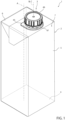
Figure 1 is a schematic perspective view of a package having a main body and an opening device according to a first embodiment of the present invention, with parts removed for clarity; -
Figure 2 is an exploded view of the opening device ofFigure 1 , with parts removed for clarity; -
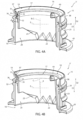
Figures 3a and 3b are sectioned perspective views of portions of the opening device ofFigure 1 being in two different configurations, with parts removed for clarity; and -
Figures 4a and 4b are sectioned perspective views of portions of an opening device according to a second embodiment of the present invention being in two different configurations, with parts removed for clarity. - Number 1 indicates as a whole a package, in particular a composite package, comprising:
- a
main body 2, preferentially a composite main body, even more particular a sealed composite main body, being filled with a pourable product, preferentially a pourable food product, and preferentially having a designated pour opening (not shown and known as such) configured to allow for the outpouring of the pourable product frommain body 2; and - an
opening device 3, preferentially an opening device formed from a polymer, fitted tomain body 2, preferentially tomain body 2 about the designated pour opening. -
Main body 2 may be obtained from a multilayer packaging material, preferentially being provided in the form of a web. The packaging material may comprise at least a layer of fibrous material, such as e.g. paper or cardboard, and at least two layers of heat-seal plastic material, e.g. polyethylene, interposing the layer of fibrous material in between one another. One of these two layers of heat-seal plastic material may define an inner face ofmain body 2 contacting the pourable product. - According to some possible embodiments, the packaging material may also comprise a layer of gas- and light-barrier material, e.g. aluminum foil or ethylene vinyl alcohol (EVOH) film, in particular being arranged between one of the layers of the heat-seal plastic material and the layer of fibrous material. More preferentially, the packaging material may also comprise a further layer of heat-seal plastic material being interposed between the layer of gas- and light-barrier material and the layer of fibrous material.
- According to a preferred non-limiting embodiment, each
opening device 3 may be applied to the respectivemain body 2 prior, during or after forming, filling and sealing of the respectivemain body 2 by means of a molding process and/or adhesive bonding and/or ultrasonic bonding and/or welding. - Alternatively, each
opening device 3 can be applied onto the packaging material prior to arranging the packaging material within or during advancement of the packaging material within a packaging machine for forming, filling and sealing the respectivemain body 2 from the packaging material. - According to some possible non-limiting embodiments,
main body 2 may contain a pourable food product such as water, milk, milk-based drinks, yoghurt drinks, coffee-based drinks, fruit juice, beverages with pulp, tomato sauce, salt, sugar and the like. - With particular reference to
Figure 1 ,main body 2 may extend along a central (longitudinal) axis A. - In more detail,
package 2 may comprise afirst wall 4, preferentially being transversal, more preferentially perpendicular, to central axis A, from whichmain body 2 extends along central axis A. Preferentially,first wall 4 may define a supporting surface ofpackage 2, which, in use, can be put in contact with a support element, such as e.g. a shelf, when, in use, being e.g. exposed within a sales point, placed within a storage chamber, placed within a refrigerator or similar. More preferentially, when being arranged on a support elementfirst wall 4 may define a bottom wall of package 1, preferentiallymain body 2. - Moreover,
main body 2 may also comprise aside wall 5 being (fixedly) connected tofirst wall 4 and extending fromfirst wall 4. - Additionally,
main body 2 may also comprise asecond wall 6 opposite tofirst wall 4 and being (fixedly) connected toside wall 5. In other words,side wall 5 may be interposed betweenfirst wall 4 andsecond wall 6. In particular, when being arranged on a support element,second wall 6 may define a top wall of package 1, preferentiallymain body 2. - According to some possible non-limiting embodiments,
first wall 4 andsecond wall 6 may be parallel to one another. - Alternatively,
first wall 4 andsecond wall 6 may be inclined with respect to one another. In other words,second wall 6 may define a slanted-top or a gable-top. - Preferentially,
second wall 6 may comprise the designated pour opening and openingdevice 3 may be fitted ontosecond wall 6. - Furthermore,
main body 2 may comprise a separation membrane covering the designated pour opening so as to isolate aninner space 7 ofmain body 2 from an outer environment. Additionally, the separation membrane may be at least partially (and non-reversibly) breakable (i.e. openable and/or rupturable and/or cuttable and/or pierceable), in particular so as to allow a loss of the integrity of the separation membrane, which therefore allows the outpouring of the pourable product out ofmain body 2. - Preferentially, the separation membrane may comprise a gas- and light-barrier material, e.g. aluminum foil or ethylene vinyl alcohol (EVOH) film.
- According to a preferred non-limiting embodiment, the separation membrane may be defined by a portion of the packaging material, in particular a portion of the layers of the packaging material being different from the layer of fibrous material. Preferentially, the separation membrane may comprise a portion of the layer of the gas- and light-barrier material.
- With particular reference to
Figures 1 to 4 ,opening device 3 comprises at least: - a
collar 15, preferentially aligned with the designated pour opening, delimiting aflow channel 16 for the pourable product; and - a
cutter 17 configured to break (i.e. to rupture and/or cut and/or pierce and/or open) the separation membrane and being at least partially arranged withincollar 15 and/orflow channel 16. - In more detail,
collar 15 may comprise aninlet opening 18 configured to allow entry of the pourable product, preferentially frominner space 7, intoflow channel 16 and apouring outlet 19 configured to allow exit of the pourable product from flow channel 16 (and collar 15). - Preferentially,
flow channel 16 may extend between inlet opening 18 and pouringoutlet 19. - In even more detail, in use and once the integrity of the separation membrane is lost due to operation of cutter 17 (see for more details further below), the pourable product can flow from
inner space 7 through the designated pour opening and/or inlet opening 18 intoflow channel 16 and then throughflow channel 16 and out of pouringoutlet 19. - In more detail,
collar 15 may comprise aninner surface 20 facing and/or delimitingflow channel 16, and preferentially also anouter surface 21 opposite to inner surface 20 (i.e. facing away from flow channel 16). - Preferentially,
inner surface 20 may also facecutter 17 withcutter 17 being at least partially arranged withinflow channel 16. - Moreover,
collar 15 and/orflow channel 16 may extend along a central axis B. - Preferentially,
collar 15 may have an annular cross-section profile in a cross-sectional plane being perpendicular to central axis B. - Even more preferentially,
collar 15 and/or inlet opening 18 and/or pouringoutlet 19 may have a (substantially) circular cross-sectional profile, preferentially in a cross-sectional plane perpendicular to central axis B. -
Cutter 17 may be arranged, in particular moveably arranged, withinflow channel 16. - Preferentially,
cutter 17 may extend along and/or have a central axis C. - Preferentially, central axis C may be coaxial to central axis B with
cutter 17 being at least partially placed withinflow channel 16. In other words,cutter 17 when being at least partially arranged withinflow channel 16 may be coaxial tocollar 15. - Preferentially,
cutter 17 may comprise at least acutting section 22 configured to break the separation membrane. More preferentially, cuttingsection 22 may comprise, even more preferentially consist of, a (curved) saw blade. - Moreover, cutting
section 22 may be arranged at afirst end portion 23 ofcutter 17. - Preferentially,
cutter 17 may be controlled in a rest position in whichcutter 17 is detached from the separation membrane (so as to guarantee integrity of the separation membrane) and an active position in whichcutter 17, inparticular cutting section 22, may be configured to break the separation membrane. - More preferentially, when package 1 is provided to an end customer,
cutter 17 is arranged in the rest position and the separation membrane is intact. Moreover, control ofcutter 17 from the rest position to the active position may be actuated once. After the separation membrane has been broken, it is not necessary to repeatedly controlcutter 17 between the active position and the rest position. In other words, after the separation membrane has been broken,control cutter 17 remains in the active position. -
Cutter 17 may be arranged in a first axial position and a second axial position with respect to central axis B when being in respectively the rest position and the active position. - Preferentially,
cutter 17, when being in the rest position and/or the first axial position, may be (substantially) fully arranged withinflow channel 16. -
Cutter 17, when being in the active position and/or the second axial position, may at least partially extend out offlow channel 16 and throughinlet opening 18. Preferentially, at least cuttingsection 22 may extend out offlow channel 16 and throughinlet opening 18. - In further detail,
cutter 17, when being in the rest position, may be closer to pouringoutlet 19 than when being in the active position. - As will be explained in more detail further below,
cutter 17 may be configured to at least translate along central axis B and/or central axis C when, in use, moving between the rest position and the active position. Preferentially,cutter 17 may be configured to translate along and rotate about central axis B and/or central axis C when, in use, moving between the rest position and the active position. - Preferentially, in use, during movement between the rest position and the
active position cutter 17 moves along a first direction D1. - More specifically,
cutter 17 may be ring-shaped (i.e. having a cross-section with an annular shape in a plane perpendicular to central axis C). -
Cutter 17 may comprise anouter surface 24 facinginner surface 20, in particular at least withcutter 17 being in the rest position. - Preferentially,
opening device 3 may comprise an actuation device configured to actuate and guide movement ofcutter 17 from the rest position to the active position. -
Opening device 3 further comprises a retaining device configured to block movement ofcutter 17 out offlow channel 16 and through pouringoutlet 19. In other words, the retaining device guarantees thatcutter 17 cannot (accidently) exit fromflow channel 16 through pouringoutlet 19. - The retaining device is configured to induce a rotation of
cutter 17 about a rotation axis E transversal to central axis B and/or central axis C, preferentially leading to a jamming ofcutter 17 withinflow channel 16 and/orcollar 15. - As will be explained in further detail, in case that
cutter 17 may (accidently) move towards pouringoutlet 19 the retaining device guarantees thatcutter 17 rotates about rotation axis E prior to reaching pouringoutlet 19. This again leads tocutter 17 becoming inclined with respect to central axis B and engaging withinner surface 20. - With particular reference to
Figures 2 to 3b , the retaining device may comprise: - a retaining
element 31 connected to, preferentially protruding from, inner surface 20 (and into flow channel 16); and - an
interaction element 32 connected to, and preferentially protruding from,cutter 17, more preferentiallyouter surface 24. - Furthermore, retaining
element 31 andinteraction element 32 are configured to interact with one another so as to induce the rotation ofcutter 17 about rotation axis E, preferentially leading to the jamming ofcutter 17 within theflow channel 16 and/orcollar 15. - More specifically, during a(n) (accidentally occurring) movement of
cutter 17 along a second direction D2 opposite to first direction D1,interaction element 32 interacts with retainingelement 31 which leads to actuation of the angular movement ofcutter 17 about rotation axis E. This again leads to the inclination ofcutter 17 with respect to central axis B and the successive jamming ofcutter 17 withinflow channel 16. -
Figure 3a illustratescutter 17 being in its rest position andFigure 3b showscutter 17 in a jammed configuration. Whencutter 17 is jammed, central axis C is inclined with respect to central axis B. - In particular, retaining device may comprise only a
single retaining element 31 and/or a single andunilateral retaining element 31. - Moreover, retaining
element 31 may be locally restricted, i.e. retainingelement 31 may have a limited local extension. - More precisely, retaining
element 31 may extend between a firstangular position 33 and a secondangular position 34 about central axis B. Preferentially, a difference between firstangular position 33 and secondangular position 34 may be less than 10°, preferentially less than 5°, more preferentially less than 3°. - According to some possible embodiments, a width (i.e. corresponding to the difference between first
angular position 33 and secondangular position 34 of retainingelement 31 may range between 1.2 mm and 1.8 mm, preferentially between 1.3 mm and 1.7 mm, even more preferentially between 1.4 mm and 1.6 mm. According to some embodiments, the width of retainingelement 31 may equal 1.5 mm. - More specifically, retaining
element 31 may radially protrude frominner surface 20 towards a center ofcollar 15 and/or towards central axis B. - Preferentially, retaining
element 31 and/orinteraction element 32 may be interposed betweenouter surface 24 andinner surface 20. - According to some preferred non-limiting embodiments, a maximum radial extension d of retaining
element 31 substantially equals, preferentially equals, the difference between an inner diameter of collar 15 (i.e. a radial distance between a first portion ofinner surface 20 and a second portion ofinner surface 20 opposite to the first portion of inner surface 20) and an outer diameter of cutter 17 (i.e. a radial distance between a first portion ofouter surface 24 and a second portion ofouter surface 24 opposite to the first portion of outer surface 24). - In particular, maximum radial extension d of retaining
element 31 may be determined as the distance betweeninner surface 20 and the farthest radial extension of retainingelement 31 intoflow channel 16. - Preferentially, maximum radial extension d of retaining
element 31 may be at least or may be larger than 0.7 mm. According to some embodiments, maximum radial extension d of retainingelement 31 may equal 0.9 mm. - This guarantees a good control of the angular movement of
cutter 17 about rotation axis E and an easy demolding ofcutter 17 during manufacturing. - In further detail, retaining
element 31 may comprise anabutment surface 35, preferentially facinginlet opening 18. - Moreover,
interaction element 32 may have anengagement surface 36, preferentially facing pouringoutlet 19. -
Engagement surface 36 may be configured to abut againstabutment surface 35, preferentially during a(n) (accidental) movement ofcutter 17 along second direction D2, so as induce the angular movement ofcutter 17 about rotation axis E and so as to guarantee the jamming ofcutter 17 withinflow channel 16 and/orcollar 15. - According to some preferred non-limiting embodiments,
abutment surface 35 may be inclined with respect to central axis B and/orinner surface 20. - Preferentially,
abutment surface 35 may define together withinner surface 20 an angle ranging between 140° and 160°, preferentially between 145° and 155°. In particular, such an angle is favorable with regard to a demolding operation. - According to some preferred non-limiting embodiments, retaining
element 31 may also comprise a guidingsurface 37 facing pouringoutlet 19 and configured to allow for a facilitated insertion ofcutter 17 intoflow channel 16 and/orcollar 15. - Preferentially, guiding
surface 37 may be inclined with respect to central axis B and/orinner surface 20. - According to some preferred non-limiting embodiments, retaining
element 31 may be integral tocollar 15 and/orinteraction element 32 may be integral tocutter 17. Even more preferentially, retainingelement 31 andcollar 15 may be molded in a single piece and/orcutter 17 andinteraction element 32 may be molded in a single piece. - According to some preferred non-limiting embodiments, retaining
element 31 may be formed as a solid protuberance. - With particular reference to
Figures 2 to 3b ,cutter 17 may comprise asecond end portion 38 opposite tofirst end portion 23. - According to some preferred non-limiting embodiments,
cutter 17 may also comprise aflange 39. -
Flange 39 may be designed to stabilize movement ofcutter 17 withinflow channel 16. - In more detail,
flange 39 may interact withcollar 15, preferentiallyinner surface 20, for stabilizing movement ofcutter 17, preferentially when moving from the respective rest position to the respective active position. - Preferentially,
flange 39 may comprise at least twoflange elements 40 angularly displaced from one another about central axis C. - By having spaced apart
flange elements 40 it is possible to easily arrangecutter 17 withinflow channel 16. - In more detail and with particular reference to
Figure 2 , eachflange element 40 may radially protrude fromcutter 17, preferentially fromsecond end portion 38 ofcutter 17 opposite tofirst end portion 23. - Preferentially, each
flange element 40 may radially protrude away from the respective central axis C. - Preferentially, each
flange element 40 may protrude towardsinner surface 20 and/or away from a center ofcutter 17. - According to the example embodiment shown, each
flange element 40 may comprise and/or or may be defined by a plate, in particular a plate perpendicular to central axis C. - Preferentially, each
flange element 40 may be arc-shaped. - Preferentially, each
flange element 40 may have the same size as the other flange element(s) 40. - In further detail and with particular reference to
Figures 1 to 3b ,opening device 3 may also comprise - a
base frame 45 configured to be fitted and/or being fitted onmain body 2, in particularsecond wall 6, and about the designated pour opening and carryingcollar 15; and - a
closure 46 configured to selectively open and close pouringoutlet 19. - Moreover,
opening device 3 may also comprise acoupling ring 47 rotatably arranged aroundcollar 15, in particular such thatcoupling ring 47 is inseparable fromcollar 15. - According to some possible non-limiting embodiments not shown, each
opening device 3 may also comprise a connection element, preferentially a tethering element, connected to, preferentially non-rupturably connected to,coupling ring 47 andclosure 46. - Advantageously,
closure 46 may be controllable in at least: - a closing position (see
Figure 1 ) in whichclosure 4 6 may be configured to cover and/or may cover pouringoutlet 19, preferentially for impeding an outflow of the pourable product fromcollar 15; and - an opening position (not specifically shown) in which
closure 46 may be configured to be and/or may be detached from pouringoutlet 19 so as to allow for an outflow of the pourable product. - In particular,
closure 46 may be rotatably coupled (about central axis B) tocollar 15 when being in the closing position. - Advantageously,
opening device 3 may comprise an actuation device partially associated to (and/or connected to and/or carried by)collar 15, partially associated to (and/or connected to and/or carried by)closure 46 and partially associated tocutter 17 and being configured such that a rotation ofclosure 46 about central axis B may movecutter 17 from the rest position to the active position. - According to some preferred non-limiting embodiments, the actuation device may comprise first interaction members (not shown), preferentially flaps, connected to
closure 46, andsecond interaction members 48 connected to, in particular integrally connected to,cutter 17. - Preferentially, the actuation device may also comprise a cam mechanism connected to
collar 15 and/orcutter 17 and configured to guide movement ofcutter 17 from the rest position to the active position. - Preferentially, the cam mechanism may comprise a
cam structure 49 connected to, preferentially integrally connected to, and protruding fromcutter 17 and a plurality ofcam elements 50 connected to, in particular integrally connected to,collar 15. - According to some preferred non-limiting embodiments, at least a portion of
cam structure 49 may defineinteraction element 32. - In particular, the first interaction members and
second interaction members 48 may be configured to interact with one another for actuating movement ofcutter 17 from the rest position to the active position. - Even more particular, a rotation of the first interaction members about central axis B may be actuated for moving
cutter 17, in particular by means of a rototranslatory movement, from the rest position to the active position. - In use, outpouring of the pourable product from package 1, in particular
main body 2, requires opening of pouringoutlet 19 and breaking of the separation membrane. - The separation membrane is broken by moving
cutter 17 from the rest position to the active position. This is achieved by the first interaction members rotating about central axis B. - With reference to
Figures 4a and 4b , number 3' indicates an alternative embodiment of an opening device according to the present invention; as opening device 3' is similar toopening device 3, the following description is limited to the differences between them, and using the same references, where possible, for identical or corresponding parts. - In particular, opening device 3' differs from opening
device 3 in that retainingelement 31 is hollow, thereby reducing the amount of plastic used. - In other words, retaining
element 31 may be formed as a hollow protuberance. In other words, each retainingelement 33 may comprise a respective cavity. - In more detail, according to such an
embodiment retaining element 31 may comprise, preferentially may consist of, a curvedsolid wall 51. Preferentially,solid wall 51 may delimit and/or define the respective hollow protuberance and/or the respective cavity. - Preferentially,
solid wall 51 may protrude towards the center ofcollar 15 and/or towards central axis B. - More specifically, retaining
element 33, preferentiallysolid wall 51, may be convexly shaped towards the center ofcollar 15 and/or towards central axis B. - Advantageously,
solid wall 51 may be integral toinner surface 20. - In more detail, retaining
element 33, preferentiallysolid wall 51, may define a respective indentation and/or groove inouter surface 24. - Moreover,
solid wall 51 may have a thickness, preferentially a (substantially) constant thickness. Preferentially, the thickness ofsolid wall 51 corresponds to the thickness of the portions ofcollar 15 adjacent to and connected tosolid wall 51 and/or of one or more other portions ofcollar 15. - The advantages of
opening device 3 and/or package 1 according to the present invention will be clear from the foregoing description. - In particular, by providing for the retaining device one guarantees that
cutter 17 cannot exit fromflow channel 16 and through pouringoutlet 19. Additionally, the Applicant has observed that retainingelement 31 can be easily demoulded, i.e. extracted from the forming mold during the manufacturing process. - Clearly, changes may be made to opening
device 3 or 3' and/or package 1 as described herein without, however, departing from the scope of protection as defined in the accompanying claims.
Claims (15)
- Opening device (3, 3') for a package (1), in particular a composite package, having a designated pour opening covered with a separation membrane and filled with a pourable product;the opening device (3, 3') comprises at least:- a collar (15) having a central axis (B) and delimiting a flow channel (16) extending between an inlet opening (18) of the collar (15) configured to allow entry of the pourable product into the flow channel (16) and a pouring outlet (19) of the collar (15) configured to allow exit of the pourable product from the flow channel (16); and- a cutter (17) configured to break the separation membrane and being at least partially arranged within the flow channel (16);wherein the collar (15) comprises an inner surface (20) facing the flow channel (16);wherein the opening device (3, 3') further comprises a retaining device configured to block movement of the cutter (17) out of the flow channel (16) and through the pouring outlet (19) by inducing a rotation of the cutter (17) about a rotation axis (E) transversal to the central axis (B);wherein the retaining device comprises a retaining element (31) protruding from the inner surface (20) of the collar (15) and an interaction element (32) connected to the cutter (17);wherein the retaining element (31) and the interaction element (32) are configured to interact with one another so as to induce the rotation of the cutter (17) about the rotation axis (E).
- Opening device according to claim 1, wherein the retaining element (31) and the interaction element (32) are configured such that the rotation of the cutter (17) about the rotation axis (E) leads to a jamming of the cutter (17) within the flow channel (16).
- Opening device according to claim 1 or 2, wherein the retaining device comprises only a single retaining element (31) and/or a single unilateral retaining element (31) .
- Opening device according to any one of the preceding claims, wherein the retaining element (31) extends between a first angular position (33) and a second angular position (34) about the central axis (B);
wherein a difference between the first angular position (33) and the second angular position (34) is less than 10°. - Opening device according to any one of the preceding claims, wherein a maximum radial extension (d) of the retaining element (31) substantially equals the difference between an inner diameter of the collar (15) and an outer diameter of the cutter (17).
- Opening device according to any one of the preceding claims, wherein a maximum radial extension (d) of the retaining element 31 is at least or is larger than 0.7 mm.
- Opening device according to any one of the preceding claims, wherein the retaining element (31) comprises a guiding surface (37) facing the pouring outlet (19) and configured to allow for a facilitated insertion of the cutter (17) into the flow channel (16).
- Opening device according to any one of the preceding claims, wherein the retaining element (31) comprises an abutment surface (35) and the interaction element (32) comprises an engagement surface (36);
wherein the engagement surface (36) is configured to abut against the abutment surface (35) leading to the rotation of the cutter (17) around the rotation axis (E). - Opening device according to claim 8, wherein the abutment surface (35) is inclined with respect to the central axis (B) and/or the inner surface (20).
- Opening device according to claim 9, wherein the abutment surface (35) defines together with the inner surface (20) an angle ranging between 140° and 160°.
- Opening device according to any one of the preceding claims, wherein the retaining element (31) is integrally connected to the inner surface of the collar (15) .
- Opening device according to any one of the preceding claims, wherein the retaining element (31) is formed by a hollow protuberance or as a solid protuberance.
- Opening device according to any one of the preceding claims, wherein the cutter (17) is arrangeable in a rest position in which the cutter (17) is detached from the separation membrane and an active position in which the cutter (17) is configured to break the separation membrane;
wherein the opening device (3, 3') also comprises an actuation device configured to actuate movement of the cutter (17) from the rest position to the active position. - Opening device according to any one of the preceding claims, and further comprising:- a base frame (45) configured to be fitted and/or being fitted on the main body (2) and about the designated pour opening and carrying collar (15); and- a closure (46) configured to selectively open and close the pouring outlet (19).
- Package (1) comprising:- a main body (2) filled with a pourable product and having a designated pour opening covered with a separation membrane; and- an opening device (3, 3') according to any one of the preceding claims fitted about the designated pour opening.
Applications Claiming Priority (1)
| Application Number | Priority Date | Filing Date | Title |
|---|---|---|---|
| IT102023000000474A IT202300000474A1 (en) | 2023-01-16 | 2023-01-16 | OPENING DEVICE FOR A PACKAGE AND PACKAGE HAVING AN OPENING DEVICE |
Publications (1)
| Publication Number | Publication Date |
|---|---|
| EP4400439A1 true EP4400439A1 (en) | 2024-07-17 |
Family
ID=85685636
Family Applications (1)
| Application Number | Title | Priority Date | Filing Date |
|---|---|---|---|
| EP23218480.4A Pending EP4400439A1 (en) | 2023-01-16 | 2023-12-20 | Opening device for a package and package having an opening device |
Country Status (7)
| Country | Link |
|---|---|
| EP (1) | EP4400439A1 (en) |
| JP (1) | JP2026500603A (en) |
| CN (1) | CN120500443A (en) |
| AU (1) | AU2023424801A1 (en) |
| IT (1) | IT202300000474A1 (en) |
| MX (1) | MX2025006044A (en) |
| WO (1) | WO2024153431A1 (en) |
Citations (3)
| Publication number | Priority date | Publication date | Assignee | Title |
|---|---|---|---|---|
| US20120181281A1 (en) * | 2004-11-15 | 2012-07-19 | Gregor Ott | Flat self-opening closure for composite packagings or for container nozzles or bottle necks to be closed by film material |
| WO2017207227A1 (en) * | 2016-05-31 | 2017-12-07 | Sig Technogoly Ag | Pouring element for a composite packaging and a composite packaging comprising a pouring element |
| EP3943408A1 (en) * | 2020-07-24 | 2022-01-26 | SIG Technology AG | Pouring element with securing cutting element guide |
-
2023
- 2023-01-16 IT IT102023000000474A patent/IT202300000474A1/en unknown
- 2023-12-20 WO PCT/EP2023/086907 patent/WO2024153431A1/en not_active Ceased
- 2023-12-20 AU AU2023424801A patent/AU2023424801A1/en active Pending
- 2023-12-20 CN CN202380090276.0A patent/CN120500443A/en active Pending
- 2023-12-20 JP JP2025525808A patent/JP2026500603A/en active Pending
- 2023-12-20 EP EP23218480.4A patent/EP4400439A1/en active Pending
-
2025
- 2025-05-23 MX MX2025006044A patent/MX2025006044A/en unknown
Patent Citations (3)
| Publication number | Priority date | Publication date | Assignee | Title |
|---|---|---|---|---|
| US20120181281A1 (en) * | 2004-11-15 | 2012-07-19 | Gregor Ott | Flat self-opening closure for composite packagings or for container nozzles or bottle necks to be closed by film material |
| WO2017207227A1 (en) * | 2016-05-31 | 2017-12-07 | Sig Technogoly Ag | Pouring element for a composite packaging and a composite packaging comprising a pouring element |
| EP3943408A1 (en) * | 2020-07-24 | 2022-01-26 | SIG Technology AG | Pouring element with securing cutting element guide |
Also Published As
| Publication number | Publication date |
|---|---|
| MX2025006044A (en) | 2025-07-01 |
| JP2026500603A (en) | 2026-01-08 |
| WO2024153431A1 (en) | 2024-07-25 |
| IT202300000474A1 (en) | 2024-07-16 |
| CN120500443A (en) | 2025-08-15 |
| AU2023424801A1 (en) | 2025-04-10 |
Similar Documents
| Publication | Publication Date | Title |
|---|---|---|
| EP3689771B1 (en) | Spout for a package and package-spout assembly | |
| US12365510B2 (en) | Spout for a container and package-spout assembly | |
| US12252311B2 (en) | Lid-spout assembly for a package and package having a lid-spout assembly | |
| EP4299460B1 (en) | Opening device for a package and package therewith | |
| US20250256885A1 (en) | Opening device for a package and package therewith | |
| JP6965287B2 (en) | Sheet packaging materials and sealed packages for manufacturing sealed packages of injectable foods | |
| US20240217698A1 (en) | Opening device for a package and package | |
| WO2024153431A1 (en) | Opening device for a package and package having an opening device | |
| EP4124584A1 (en) | Opening device for a package and package having an opening device | |
| EP4592209A1 (en) | Opening device for a package and package | |
| EP4674781A1 (en) | Opening device for a package and package having an opening device |
Legal Events
| Date | Code | Title | Description |
|---|---|---|---|
| PUAI | Public reference made under article 153(3) epc to a published international application that has entered the european phase |
Free format text: ORIGINAL CODE: 0009012 |
|
| STAA | Information on the status of an ep patent application or granted ep patent |
Free format text: STATUS: THE APPLICATION HAS BEEN PUBLISHED |
|
| AK | Designated contracting states |
Kind code of ref document: A1 Designated state(s): AL AT BE BG CH CY CZ DE DK EE ES FI FR GB GR HR HU IE IS IT LI LT LU LV MC ME MK MT NL NO PL PT RO RS SE SI SK SM TR |
|
| STAA | Information on the status of an ep patent application or granted ep patent |
Free format text: STATUS: REQUEST FOR EXAMINATION WAS MADE |
|
| 17P | Request for examination filed |
Effective date: 20250117 |