EP4400423A1 - Passenger seat tray table - Google Patents
Passenger seat tray table Download PDFInfo
- Publication number
- EP4400423A1 EP4400423A1 EP23151832.5A EP23151832A EP4400423A1 EP 4400423 A1 EP4400423 A1 EP 4400423A1 EP 23151832 A EP23151832 A EP 23151832A EP 4400423 A1 EP4400423 A1 EP 4400423A1
- Authority
- EP
- European Patent Office
- Prior art keywords
- tray table
- armrest
- passenger seat
- deployed configuration
- seat
- Prior art date
- Legal status (The legal status is an assumption and is not a legal conclusion. Google has not performed a legal analysis and makes no representation as to the accuracy of the status listed.)
- Pending
Links
Images


Classifications
-
- B—PERFORMING OPERATIONS; TRANSPORTING
- B64—AIRCRAFT; AVIATION; COSMONAUTICS
- B64D—EQUIPMENT FOR FITTING IN OR TO AIRCRAFT; FLIGHT SUITS; PARACHUTES; ARRANGEMENT OR MOUNTING OF POWER PLANTS OR PROPULSION TRANSMISSIONS IN AIRCRAFT
- B64D11/00—Passenger or crew accommodation; Flight-deck installations not otherwise provided for
- B64D11/06—Arrangements of seats, or adaptations or details specially adapted for aircraft seats
- B64D11/0638—Arrangements of seats, or adaptations or details specially adapted for aircraft seats with foldable tables, trays or cup holders
-
- B—PERFORMING OPERATIONS; TRANSPORTING
- B60—VEHICLES IN GENERAL
- B60N—SEATS SPECIALLY ADAPTED FOR VEHICLES; VEHICLE PASSENGER ACCOMMODATION NOT OTHERWISE PROVIDED FOR
- B60N2/00—Seats specially adapted for vehicles; Arrangement or mounting of seats in vehicles
- B60N2/75—Arm-rests
- B60N2/763—Arm-rests adjustable
- B60N2/77—Height adjustment
-
- B—PERFORMING OPERATIONS; TRANSPORTING
- B60—VEHICLES IN GENERAL
- B60N—SEATS SPECIALLY ADAPTED FOR VEHICLES; VEHICLE PASSENGER ACCOMMODATION NOT OTHERWISE PROVIDED FOR
- B60N3/00—Arrangements or adaptations of other passenger fittings, not otherwise provided for
- B60N3/001—Arrangements or adaptations of other passenger fittings, not otherwise provided for of tables or trays
- B60N3/002—Arrangements or adaptations of other passenger fittings, not otherwise provided for of tables or trays of trays
-
- B—PERFORMING OPERATIONS; TRANSPORTING
- B64—AIRCRAFT; AVIATION; COSMONAUTICS
- B64D—EQUIPMENT FOR FITTING IN OR TO AIRCRAFT; FLIGHT SUITS; PARACHUTES; ARRANGEMENT OR MOUNTING OF POWER PLANTS OR PROPULSION TRANSMISSIONS IN AIRCRAFT
- B64D11/00—Passenger or crew accommodation; Flight-deck installations not otherwise provided for
- B64D11/06—Arrangements of seats, or adaptations or details specially adapted for aircraft seats
- B64D11/0639—Arrangements of seats, or adaptations or details specially adapted for aircraft seats with features for adjustment or converting of seats
- B64D11/0644—Adjustable arm rests
Definitions
- the present invention relates to passenger seat tray tables.
- a passenger seat assembly for an aircraft and a method of positioning a tray table of a passenger seat assembly for an aircraft, are contemplated herein.
- a tray table provides a passenger with a flat surface on which they may place a number of objects and, particularly in the case of air travel, have a meal.
- Passenger seats for vehicles often have to strike a balance between comfort of the passenger, the durability of the passenger seat, and the compactness of the passenger seat. Since passenger seats will experience use from a great number of passengers during their operational lifetime, passenger seats are often designed with an average consumer or passenger in mind. Accordingly, passenger seats and their specific features, such as tray tables, may not facilitate the comfort of all passengers who use them.
- a passenger seat assembly for an aircraft comprising: a seat having a front side and a back side separated from one another in a depthwise direction, and a first lateral side and a second lateral side separated from one another in a widthwise direction; and an armrest located at one of the first lateral side or the second lateral side of the seat, the armrest comprising a tray table movable between a stowed configuration and a deployed configuration; wherein a position of the tray table is adjustable, relative to the seat, in the depthwise direction and in a heightwise direction when in the deployed configuration.
- the armrest may comprise a heightwise adjustment mechanism configured to control a height of the armrest relative to the seat; and the position of the tray table relative to the seat may be adjustable in the heightwise direction when in the deployed configuration by actuating the height adjustment mechanism of the armrest.
- the armrest may comprise a first armrest portion and a second armrest portion coupled by the height adjustment mechanism.
- the height adjustment mechanism may be configured to telescopically extend so as to move the second arm portion relative to the first arm portion between a number of discrete positions in the heightwise direction.
- the tray table may be slidably attached to the armrest via a sliding rail mechanism extending in the depthwise direction; and the position of the tray table relative to the seat may be adjustable in the depthwise direction when in the deployed configuration by actuating the sliding rail mechanism.
- the tray table may be housed in the armrest in the stowed configuration.
- the tray table may be configured to be moved from the stowed configuration to the deployed configuration by translating the tray table upwards relative to the seat, and by subsequently rotating the tray table out of the armrest and upwards into the deployed configuration.
- the armrest may comprise a cavity configured to house the tray table in the armrest when the tray table is in the stowed configuration.
- the armrest may comprise a first releasable cover configured to provide a surface for a passenger arm and to cover the tray table when the tray table is in the stowed configuration; wherein the first releasable cover is configured to be opened when the tray table is to be moved from the stowed configuration to the deployed configuration.
- the armrest may comprise a second releasable cover configured to enclose a front side opening of the cavity when the tray table is in the stowed configuration.
- the second releasable cover may be configured to automatically open when the tray table is moved in the forward direction.
- a supporting arm of the tray table may be rotatably mounted to a mounting member of the armrest.
- the tray table may comprise a first locking member configured to engage a second locking member of the mounting member to thereby prevent rotation between the supporting arm and the mounting member when the tray table is in the deployed configuration.
- the supporting arm may comprise a third locking member configured to be in rotational alignment with the second locking member only when the tray table is in the deployed configuration; wherein the first locking member is configured to engage the second locking member and the third locking member to thereby prevent rotation between the supporting arm and the mounting member when the tray table is in the deployed configuration.
- a width of the tray table may be adjustable when in the deployed configuration.
- the width of the tray table may be adjustable by action of a folding mechanism.
- the folding mechanism may comprise a flexible linear joint formed between a first tray table portion and a second tray table portion.
- a bank of passenger seat assemblies comprising: a plurality of seats each having a front side and a back side separated from one another in a depthwise direction, and a first lateral side and a second lateral side separated from one another in a widthwise direction; and a plurality of armrests, each armrest located at one of the first lateral side or the second lateral side of each seat, each armrest comprising a tray table movable between a stowed configuration and a deployed configuration; wherein a position of each tray table relative to the seat is adjustable in the depthwise direction and a heightwise direction when in the deployed configuration.
- the bank of passenger seat assemblies may comprise a passenger seat assembly according to the first aspect, or a plurality of passenger seat assemblies according to the first aspect.
- the plurality of seats may include the seat(s) or may be a plurality of the seats; and the plurality of armrests may include the armrest(s) or may be a plurality of the armrests.
- an aircraft comprising: a cabin having an aisle; and at least one of: a passenger seat assembly according to the first aspect; and a bank of passenger seat assemblies according to the second aspect.
- the aircraft may comprise a first bank of passenger seat assemblies located on a port side of the aisle; and a second bank of passenger seat assemblies located on a starboard side of the aisle opposite the port side; wherein the first bank of passenger seat assemblies is the bank of passenger seat assemblies according to the second aspect, wherein each armrest of the plurality of armrests is located on a starboard side of each seat; and wherein the second bank of passenger seat assemblies is a further bank of passenger seat assemblies according to the second aspect, wherein each armrest of the plurality of armrests is located on a port side of each seat.
- a method of positioning a tray table comprising: deploying the tray table from a stowed configuration to the deployed configuration; and adjusting, in the deployed configuration, a height of the tray table relative to the seat and a depth of the tray table relative to the seat.
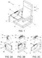
- Figure 1 shows a passenger seat assembly 100 comprising a seat 1 having a backrest 2, a first armrest 3 and a second armrest 4.
- the passenger seat assembly 100 also features a plurality of legs (not shown) that raise the seat 1 off the floor. In other embodiments, a stand or other supporting feature to raise the seat 1 off the floor can equally be employed in place of the legs.
- the passenger seat assembly 100 of the present embodiment is an aircraft passenger seat assembly, such as for a commercial aircraft. However, it will be readily apparent how the passenger seat assembly 100 may be adapted for use in other vehicles, such as trains, road vehicles or marine vessels.
- the seat 1 provides a surface suitable for the passenger to sit on the passenger seat assembly 100.
- the seat 1 has a front side from which the legs of a passenger will descend when sitting on the chair, and a back side where the backrest 2 meets the seat 1.
- the backrest 2 comprises a backrest portion 2a and a headrest portion 2b, each suitable for providing support to the passenger's back and head, respectively.
- the armrests 3, 4 are each located on a lateral side of the seat 1, providing the passenger with an upward-facing surface on which their arms may be supported.
- the first armrest 3 is located on the right lateral side of the seat 1, and the second armrest 4 is located opposite the first armrest 3, on the left lateral side of the seat 1.
- the distance between the front side of the seat 1 and the back side of the seat 1 can be considered as the depth of the seat 1.
- any extension or movement extending between the front side of the seat and the back side of the seat 1 can be considered to be in a depthwise direction.
- the distance between the left lateral side of the seat 1 and the right lateral side of the seat 1 can be considered as the width of the seat 1; and any extension or movement extending between the left lateral side of the seat 1 and the right lateral side of the seat 1 can be considered as being in a widthwise direction.
- Any extension or movement in and/or out of the plane defined by the seat 1 can be considered to be in a heightwise direction.
- the passenger will sit on the passenger seat assembly 100 facing towards the front side, with their back towards the back side of the seat 1.
- the direction in which the passenger faces is usually a direction of travel of the vehicle in which the passenger seat assembly 100 is situated.
- the first armrest 3, which is shown on the right lateral side of the seat 1, may thus be referred to as a starboard side armrest 3.
- the second armrest 4, which is shown on the left lateral side of the seat 1, may similarly be referred to as a port side armrest 4. Appreciably, these terms may be reversed where the passenger seat assembly 100 is situated with the front side of the seat 1 facing in a direction opposite to that of a direction of travel of the vehicle in which the passenger seat assembly 100 is situated.
- each armrest 3, 4 is fixed to the seat 1 on either side of the seat 1.
- each armrest may be instead fixed to a floor of the vehicle at each side of the seat 1.
- the armrests need not necessarily be fixed to the seat: they may be positioned relative to the seat 1.
- the first armrest 3 comprises a tray table 5, which is shown in a deployed configuration in figure 1 .
- the tray table 5 In the deployed configuration, the tray table 5 is configured to provide a flat surface (i.e. a surface parallel to a floor of the vehicle and/or perpendicular to the direction of gravity) on which the passenger may place one or more items.
- a flat surface i.e. a surface parallel to a floor of the vehicle and/or perpendicular to the direction of gravity
- the tray table 5 is shown in the stowed configuration in figure 6A , for example.
- the tray table 5 is movable between the stowed configuration and the deployed configuration.
- the tray table 5 when in the stowed configuration, the tray table 5 is flush, or housed by, the first armrest 3.
- the first armrest 3 comprises a guard portion 6, which may serve to protect and retain the tray table 5 when in the stowed configuration.
- the tray table 5 When in the deployed configuration, the tray table 5 is movable in the depthwise direction and the heightwise direction.
- the depthwise direction and the heightwise direction are illustrated by arrows D and H respectively, as illustrated in figure 1 .
- a passenger may be able to adjust a position of the tray table 5 in the deployed configuration to better accommodate the passenger's needs. For example, a shorter passenger may benefit from reducing the height of the tray table 5 by moving the tray table 5 towards the seat 1; whilst a taller passenger may benefit from increasing the height of the tray table 5 by moving the tray table 5 away from the seat 1.
- the passenger seat assembly 100 may provide improved comfort and usability for a greater range of passengers.
- first armrest 3 is shown comprising the tray table 5 and the second armrest 4 is shown not comprising the tray table 5, in other embodiments the second armrest may comprise the tray table 5 and the first armrest 3 may not comprise the tray table 5.
- the construction of the passenger seat assembly 100 is effectively mirrored about the centre of the passenger seat assembly in the widthwise direction.
- FIG 2A shows a perspective view of the first armrest 3, with the tray table 5 in the stowed configuration.
- the tray table 5 is stowed in the armrest 3 when in the stowed configuration.
- the armrest 5 comprises a height adjustment mechanism 10 by which a height of the armrest 3 is adjustable, relative to the seat 1.
- the height of the tray table 5 is also adjusted due to it being fixed to the armrest 3. Therefore, in the deployed configuration, the height of the tray table 5 is adjustable, relative to the seat 1, by actuating the height adjustment mechanism 10.
- the first armrest 3 comprises a first armrest portion 3a and a second armrest portion 3b.
- the tray table 5 is mounted to the second armrest portion 3b.
- the first armrest portion 3a and the second armrest portion 3b are coupled by the height adjustment mechanism 10.
- the height adjustment mechanism 10 comprises an extension 11 of the first armrest portion 3a to which the second armrest portion 3b is coupled.
- the extension 11 comprises a plurality of notches 12, which are each configured to mate with a latch 13 of the second armrest portion 3b, and are shown in closer detail in view A'.
- the latch 13 can be selectively released by operation of a depressible portion of the latch 13, enabling a passenger to adjust the height of the second armrest portion 3b, and in turn the tray table 5.
- an alternative heightwise adjustment mechanism can be used.
- the tray table 5 may be slidably mounted to the armrest portion 3 such that a height of the tray table 5 can be adjusted in the heightwise direction.
- the tray table 5 can comprise a hydraulic or motor-controlled actuator to vary a position of the tray table 5 in the heightwise direction, when in the deployed configuration.
- Figure 2B shows another perspective view of the first armrest 3, with the tray table 5 in the stowed configuration.
- the tray table 5 is fixed to the armrest 3 via a sliding rail mechanism 20, which can be seen in further detail in view B'.
- the sliding rail mechanism 20 extends along the first armrest 3 in the depthwise direction.
- the sliding rail mechanism 20 comprises a first sliding rail 21, which an arm 22 of the tray table 5 engages.
- the arm 22 is slidable along the first sliding rail 21, enabling the tray table 5 to be translated along the first sliding rail 21 relative to the armrest 3, to thereby adjust a position of the tray table 5 in the depthwise direction.
- the sliding rail mechanism 20 of the present embodiment is shown in further detail in figures 4C and 4D .
- the length of the first sliding rail 21 limits the range of movement of the tray table 5 in the depthwise direction.
- the arm 22 is at a rearmost position of the first sliding rail 21 (i.e. towards the back side of the seat 1), such that the tray table 5 is fully contained within the armrest 3.
- Figure 2C shows the first armrest 3 from a similar perspective as in figure 2B .
- the arm 22 is at a forwardmost position of the first sliding rail 21 (i.e. towards the front of the seat 1), such that the tray table 5 is extended forward of the armrest 3 as far as it will go.
- the sliding mechanism 20 of the present embodiment uses a first sliding rail 21, in other embodiments the sliding mechanism may instead use an alternative mechanism.
- the sliding mechanism could comprise a toothed rack rail and a pinion gear to facilitate translational movement between the tray table 5 and the armrest 3; or a columnar rod to which a sleeve is slidably mounted.
- the sliding mechanism 20 of the present embodiment slides the tray table 5 relative to the armrest 3 to adjust the position of the deployed tray table 5 in the depthwise direction
- alternative arrangements facilitating the depthwise adjustment of the tray table 5 are contemplated.
- the armrest 3 may be configured to be adjustable in the depthwise direction relative to the seat 1, thereby adjusting the position of the tray table 5 in the depthwise direction, relative to the seat 1, when in the deployed configuration.
- the armrest 3 may comprise a static portion fixed relative to the seat 1 and an adjustable portion coupled to the static portion by a depth adjustment mechanism, with the depth adjustment mechanism configured to telescopically extend so as to move the adjustable portion relative to the static portion, e.g. between a number of discrete positions, in the depthwise direction.
- the depth adjustment mechanism may comprise an extension of the static portion to which the adjustable portion is telescopically mounted.
- the extension may comprise a plurality of notches, which are each configured to mate with a latch of the adjustable portion, each notch providing a discrete position in which the adjustable portion can be extended relative to the static portion.
- the latch can be selectively released by operation of a depressible portion of the latch, enabling a passenger to adjust a depthwise extension of the adjustable portion relative to the static portion, and in turn the tray table relative to the seat 1.
- the depthwise adjustment of the armrest may be used in combination with the heightwise adjustment of the armrest 3 as described above.
- the armrest 3 may comprise a first armrest portion statically fixed relative to the seat 1; a second armrest portion coupled to the first armrest portion as described above, such that the second armrest portion is adjustable in the heightwise direction relative to the first armrest portion; and a third armrest portion coupled to the second armrest portion, such that the third armrest portion is adjustable in the depthwise direction relative to the second armrest portion.
- the tray table 5 can be mounted to the third armrest portion, such that a height and a depth of the tray table, in the deployed configuration, is controllable by adjusting the second portion in the heightwise direction and the third portion in the depthwise direction, respectively.
- Figures 3A-D illustrate the movement of the tray table 5 from the stowed configuration, in which the tray table 5 is housed in the first armrest 3, to the deployed configuration, in which the tray table 5 provides a flat surface, according to a preferred embodiment.
- the tray table 5 is movable between the stowed configuration and the deployed configuration by translating the tray table 5 upwards, relative to the seat 1, and by subsequently rotating the tray table 5 out of the first armrest 3 and upwards to the deployed configuration.
- the tray table 5 is rotated out and over the seat 1, and upwards to the deployed configuration, without needing to rotate around and over the armrest 3.
- the tray table 5 as illustrated in figures 3A-3D in accordance with the present embodiment, is rotated in a counter-clockwise direction rather than a clockwise direction, as part of its motion between the stowed configuration and the deployed configuration.
- the second armrest 4 comprises the tray table 5
- the tray table 5 can be moved in a clockwise direction rather than a counter-clockwise direction as it is rotated out and over the seat 1, and upwards to the deployed configuration.
- the tray table 5 By providing a tray table 5 that is moved from the stowed configuration to the deployed configuration by translating the tray table 5 upwards, relative to the seat 1, and by subsequently rotating the tray table 5 out of the armrest 3 from which it is stowed and upwards to the deployed configuration, the tray table 5 may be more compactly housed in the armrest 3 when in the stowed configuration. For example, since the tray table 5 need only be accessible from the armrest from towards the seat 1, multiple seats may be placed closer together. Additionally, a passenger may deploy the tray table 5 with a reduced risk of disturbing a neighbouring passenger, since the tray table 5 need not pass upwards and over the armrest 3 to be deployed over the seat 1.
- the second sliding rail 23 is fixed to an underside of the tray table 5.
- the arm 22, as well as being slidably mounted to each of the first and second sliding rails 21, 23, is rotatably mounted to the first and second sliding rails 21, 23 at each respective end thereof. Accordingly, the first end of the arm 22 is capable of sliding relative to the first sliding rail 21, and is also capable of rotating relative to the first sliding rail 21.
- the second end of the arm 22 is capable of sliding relative to the second sliding rail 23, and is also capable of rotating relative to the second sliding rail 23.
- the tray table 5 slides upwards in the heightwise direction via a sliding motion between the arm 22 and the second sliding rail 23, as shown in figure 3A .
- the tray table 5 slides upwards such that it clears the guard portion 6.
- the guard portion 6 has an inclined shape.
- the guard portion 6 is therefore lower towards the front side. Therefore, before moving upwards, the tray table 5 may be required to slide forwards in the depthwise direction, to help the tray table 5 clear an edge of the guard portion 6.
- the tray table 5 rotates upwards, for example by pivoting about the first end of the arm 22.
- the tray table 5 also slides outwards, i.e. towards the opposite lateral side of the seat 1, or towards the second armrest 4, by actuating the sliding mechanism formed by the second sliding rail 23 and the second end of the arm 22.
- the tray table 5 reaches the deployed configuration in which the tray table 5 lies flat, e.g. by pivoting the tray table 5 about the second end of the arm 22.
- the tray table 5 is maintained in the deployed configuration by securing a locking mechanism, as discussed below and as shown in figure 4 .
- the first armrest 3 does not comprise a guard portion 6.
- the tray table 5 may then be moved upwards, relative to the seat 1, and subsequently rotated out from the armrest 3 and upwards towards the deployed configuration, without needing to slide the tray table 5 forwards in the depthwise direction to assist the tray table 5 in clearing an edge of the guard portion 6.
- a width of the tray table 5 is adjustable when in the deployed configuration.
- the tray table 5 comprises a first tray table portion 5a and a second tray table portion 5b.
- the second tray table portion 5b is joined to the first table portion 5a via a folding mechanism 30.
- the width of the tray table 5 can be adjusted by folding out the second tray table portion 5b.
- the passenger may be able to further adjust the tray table 5 to better accommodate the passenger's needs.
- the folding mechanism 30 of the present embodiment comprises a linear joint formed between the first tray table portion 5a and the second tray table portion 5b, the linear joint comprising a flexible portion.
- the folding mechanism 30 can comprise any mechanism that facilitates a folding motion between the first tray table portion 5a and the second tray table portion 5b, such as one or more hinge joints or the like.
- the folding mechanism 30 of the present embodiment provides cantilevered support to the second tray table portion 5b when deployed.
- the second tray table portion 5b can be supported by the second armrest 4.
- Using a folding mechanism 30 to adjust a width of the tray table 5 may enable a passenger to select a size of the tray table 5 as desired when in the deployed configuration, whilst also enabling the tray table 5 to be housed in the first armrest 3 in a compact manner when in the stowed configuration.
- the second tray table portion 5b may be telescopically mounted, or slidably mounted, to the first tray table portion 5a to facilitate an adjustment of the width of the tray table 5 in the deployed configuration.
- a position of the tray table 5 may be additionally or alternatively adjusted in the widthwise direction.
- the first tray table portion 5a may be capable of being slid in the widthwise direction, e.g. via actuating the arm 22 relative to the second sliding rail 23, to adjust a position of the tray table 5 in the widthwise direction.
- the tray table 5 may comprise only the first tray table portion 5a, with the first tray table portion 5a being translatable relative to the seat 1 in the widthwise direction, such that a position of the tray table 5 is adjustable in the widthwise direction, when the tray table 5 is in the deployed configuration.
- Figures 4A-D each show a perspective view of the first armrest 3 and the tray table 5, and in particular show a locking mechanism 40 for retaining the tray table 5 in the deployed configuration.
- Figure 4A shows the tray table 5 in the stowed configuration.
- the first end of the arm 22 is slidably and rotatably coupled to the first sliding rail 21.
- a mounting member 41 is slidably coupled to the first sliding rail 21, and the first end of the arm 22 is rotatably coupled to the mounting member 41.
- the arm 22 is slidably and rotatably coupled to the first sliding rail 21.
- the underside of the tray table 5 is provided with a first locking member 42.
- the first locking member 42 is a protrusion extending from the underside of the tray table 5.
- FIG. 4C shows the mounting member 41 and the first end of the arm 22 in further detail.
- the mounting member 41 comprises a second locking member 41a which, in the present embodiment, is a first groove
- the arm 22 comprises a third locking member 22a which, in the present embodiment, is a second groove located at the first end of the arm 22.
- the second locking member 41a and the third locking member 22a are misaligned.
- the arm 22 rotates relative to the mounting member 41.
- the second locking member 41a and the third locking member 22a are configured to align.
- Figure 4D shows the locking mechanism 40 in a locked configuration.
- the first locking member 42 engages the second locking member 41a and the third locking member 22a, i.e. by engaging the channel provided by the first groove and the second groove when aligned.
- the first locking member 42 engages the second locking member 41a and the third locking member 22a via an interference fit, with lateral faces of the first locking member 42 preventing the second locking member 41a and the third locking member 22a from misaligning. Therefore, when in the locked configuration, the locking mechanism 40 prevents the arm 22 from rotating about the mounting member 41.
- the locking mechanism 40 is arranged to provide a releasable cantilever support for the tray table 5 when it is in the deployed configuration.
- the arm 22 can be referred to as a supporting arm 22, since it provides the necessary support to maintain the tray table 5 in the deployed configuration.
- the arm 22 of the tray table 5 is rotatably mounted to the mounting member 41 of the first armrest 3, and the third locking member 22a of the arm 22 is configured to align with the second locking member 41a of the armrest 3 only when the tray table 5 is in the deployed configuration. This may ensure a passenger correctly moves the tray table 5 to the deployed configuration before being able to engage the locking mechanism 40.
- the locking mechanism 40 comprises the mounting member 41 and the locking member 42
- alternative locking mechanisms are contemplated.
- the locking mechanism 40 may only comprise the first locking member 42 and the second locking member 41a.
- the tray table 5 may comprise a groove as the second locking member
- the mounting member 41 and optionally the arm 22 may comprise protrusions as the first and third locking members respectively, arranged to engage the groove in the deployed configuration.
- the armrest 3 may comprise a collapsible bracket or support member configured to be flush with the armrest 3 when the tray table 5 is in the stowed configuration, and configured to be extended when the tray table 5 is in the deployed configuration. When extended, the collapsible bracket or support member may provide a surface on which the tray table 5 can rest.
- Figure 5 shows the tray table 5 in the deployed configuration, viewed from the underside of the tray table 5.
- the tray table 5 is housed in the first armrest 3 in the present embodiment.
- the tray table 5 By housing the tray table 5 in the armrest 3, the tray table 5 may be more compactly arranged when stowed, such that the overall passenger seat assembly 100 can be made smaller. Additionally, the tray table 5 may be better protected by the armrest 3 from damage when stowed, for example if a passenger were to knock or impact the tray table 5 when passing, sitting on, or vacating, the seat 1.
- the armrest 3 defines a cavity 9 in which the tray table 5 is stowed.
- the cavity 9 is bounded by the armrest 3 on a first lateral side 9a, a back side 9b, and on a bottom side (not shown).
- the lateral side opposite to the second lateral side 9a is bounded at least partially by the guard portion 6.
- the front side and the top side of the cavity 9 are each bounded by releasable covers 7, 8.
- each of the releasable covers 7, 8 are opened such that movement of the tray table 5 is not restricted by the presence of the covers 7, 8.
- the provision of releasable covers 7, 8 may protect the tray table 5 and its respective adjustment mechanisms from damage when the tray table 5 is in the stowed configuration (e.g. when not in use).
- a front side releasable cover 7 bounds the front side of the cavity 9, and a top side releasable cover 8 bounds the top side of the cavity 9.
- each of the releasable covers 7, 8 are closed.
- the top side releasable cover 8 is closed, the top side releasable cover 8 provides a surface on which a passenger may rest their arm.
- the top side releasable cover (8) is manually opened by sliding the cover 8 around the side of the armrest 3, i.e. down the back side of the first lateral side 9a (see figures 3A-3D , for example).
- the top side releasable cover 8 is opened manually, for example by pressing a button to release a latch keeping the cover 8 in place, with the cover 8 resiliently biased to be in the open position; or by pulling a handle of the cover 8 and manually moving the cover 8 to the open position.
- the front side releasable cover 7 is configured to automatically open when the tray table 5 is moved in the forward direction.
- the tray table 5 pushes the releasable cover 7 to automatically open it.
- movement of the tray table 5 in the forward direction triggers an automatic opening mechanism arranged to open the front side releasable cover 7.
- the front side releasable cover 7 is resiliently biased to be in the open position, for example by a spring mechanism.
- the front side releasable cover 7 is maintained in the closed position by the top side releasable cover 8, by a groove or slot of the top side releasable cover 8 in which the front side releasable cover 7 is retained.
- the top side releasable cover 8 therefore has to be closed for the front side releasable cover 7 to be maintained in the closed position.
- the armrest 3 may comprise only the top side releasable cover 8, and the front side of the cavity may be bounded by a permanent wall of the armrest 3. This may be the case where the tray table 5 does not need to move in the depthwise direction to assist with clearing e.g. a guard portion 6.
- the tray table 5 can be fixed to an outer surface of the armrest 3 such that it simply sits against the surface of the armrest 3 when in the stowed configuration, rather than be housed in the armrest 3 when stowed.
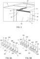
- FIG. 6A shows two banks 200 of passenger seat assemblies 100, each bank 200 comprising a plurality of seats 1 located either side of an aisle 301, e.g. in a cabin of an aircraft 300 or another vehicle.
- Each of the seats 1 and the armrests 203, 204 have a construction as described above.
- each bank 200 of passenger seat assemblies 100 is shown having three passenger seat assemblies 100, in other embodiments each bank 200 may comprise two passenger seat assemblies, or four or more passenger seat assemblies 100.
- a first plurality of the seats 1 are located on a first lateral side of an aisle 301, and a second plurality of the seats 1 are located on a second lateral side of the aisle 301, opposite the first lateral side of the aisle 301.
- Each seat 1 comprises an armrest 203, 204.
- the armrest 203, 204 closest to the aisle 301 for each seat 1 comprises a tray table 5, as discussed above.
- each of the tray tables 5 are in the stowed configuration.
- each of the tray tables 5 are in the deployed configuration.
- the side walls of the cabin of the aircraft 300 are normally arcuate, and internally concave. Accordingly, a heightwise clearance of the cabin may be reduced towards the side walls.
- the tray tables 5 By placing the tray tables 5 on the armrests 203, 204 closest to the aisle, no tray tables 5 need be provided for the armrests 203, 204 located next to a side wall of the cabin of the aircraft 300. According, the tray table 5 of both the most port side seat of the port side seat bank 200 and the most starboard side seat 1 of the starboard side seat bank 200 may be able to freely extend in the heightwise direction (e.g. during deployment or during adjustment of the tray table 5 in the deployed configuration) without its movement being restricted by the side wall of the cabin of the aircraft 300.
Landscapes
- Engineering & Computer Science (AREA)
- Aviation & Aerospace Engineering (AREA)
- Transportation (AREA)
- Mechanical Engineering (AREA)
- Passenger Equipment (AREA)
Abstract
Description
- The present invention relates to passenger seat tray tables. In particular, a passenger seat assembly for an aircraft, and a method of positioning a tray table of a passenger seat assembly for an aircraft, are contemplated herein.
- Passenger seats for vehicles such as aircraft, trains or the like are often fitted with features aimed to improve a passenger's comfort during their journey. One such feature is a tray table. In use, a tray table provides a passenger with a flat surface on which they may place a number of objects and, particularly in the case of air travel, have a meal.
- Passenger seats for vehicles often have to strike a balance between comfort of the passenger, the durability of the passenger seat, and the compactness of the passenger seat. Since passenger seats will experience use from a great number of passengers during their operational lifetime, passenger seats are often designed with an average consumer or passenger in mind. Accordingly, passenger seats and their specific features, such as tray tables, may not facilitate the comfort of all passengers who use them.
- It is desirable to improve a passenger's comfort during their journey.
- Viewed from a first aspect, there is provided a passenger seat assembly for an aircraft comprising: a seat having a front side and a back side separated from one another in a depthwise direction, and a first lateral side and a second lateral side separated from one another in a widthwise direction; and an armrest located at one of the first lateral side or the second lateral side of the seat, the armrest comprising a tray table movable between a stowed configuration and a deployed configuration; wherein a position of the tray table is adjustable, relative to the seat, in the depthwise direction and in a heightwise direction when in the deployed configuration.
- The armrest may comprise a heightwise adjustment mechanism configured to control a height of the armrest relative to the seat; and the position of the tray table relative to the seat may be adjustable in the heightwise direction when in the deployed configuration by actuating the height adjustment mechanism of the armrest.
- The armrest may comprise a first armrest portion and a second armrest portion coupled by the height adjustment mechanism.
- The height adjustment mechanism may be configured to telescopically extend so as to move the second arm portion relative to the first arm portion between a number of discrete positions in the heightwise direction.
- The tray table may be slidably attached to the armrest via a sliding rail mechanism extending in the depthwise direction; and the position of the tray table relative to the seat may be adjustable in the depthwise direction when in the deployed configuration by actuating the sliding rail mechanism.
- The tray table may be housed in the armrest in the stowed configuration.
- The tray table may be configured to be moved from the stowed configuration to the deployed configuration by translating the tray table upwards relative to the seat, and by subsequently rotating the tray table out of the armrest and upwards into the deployed configuration.
- The armrest may comprise a cavity configured to house the tray table in the armrest when the tray table is in the stowed configuration.
- The armrest may comprise a first releasable cover configured to provide a surface for a passenger arm and to cover the tray table when the tray table is in the stowed configuration; wherein the first releasable cover is configured to be opened when the tray table is to be moved from the stowed configuration to the deployed configuration.
- The armrest may comprise a second releasable cover configured to enclose a front side opening of the cavity when the tray table is in the stowed configuration.
- The second releasable cover may be configured to automatically open when the tray table is moved in the forward direction.
- A supporting arm of the tray table may be rotatably mounted to a mounting member of the armrest.
- The tray table may comprise a first locking member configured to engage a second locking member of the mounting member to thereby prevent rotation between the supporting arm and the mounting member when the tray table is in the deployed configuration.
- The supporting arm may comprise a third locking member configured to be in rotational alignment with the second locking member only when the tray table is in the deployed configuration; wherein the first locking member is configured to engage the second locking member and the third locking member to thereby prevent rotation between the supporting arm and the mounting member when the tray table is in the deployed configuration.
- A width of the tray table may be adjustable when in the deployed configuration.
- The width of the tray table may be adjustable by action of a folding mechanism.
- The folding mechanism may comprise a flexible linear joint formed between a first tray table portion and a second tray table portion.
- Viewed from a second aspect, there is provided a bank of passenger seat assemblies, comprising: a plurality of seats each having a front side and a back side separated from one another in a depthwise direction, and a first lateral side and a second lateral side separated from one another in a widthwise direction; and a plurality of armrests, each armrest located at one of the first lateral side or the second lateral side of each seat, each armrest comprising a tray table movable between a stowed configuration and a deployed configuration; wherein a position of each tray table relative to the seat is adjustable in the depthwise direction and a heightwise direction when in the deployed configuration.
- The bank of passenger seat assemblies may comprise a passenger seat assembly according to the first aspect, or a plurality of passenger seat assemblies according to the first aspect. Accordingly, the plurality of seats may include the seat(s) or may be a plurality of the seats; and the plurality of armrests may include the armrest(s) or may be a plurality of the armrests.
- Viewed from a third aspect, there is provided an aircraft comprising: a cabin having an aisle; and at least one of: a passenger seat assembly according to the first aspect; and a bank of passenger seat assemblies according to the second aspect.
- The aircraft may comprise a first bank of passenger seat assemblies located on a port side of the aisle; and a second bank of passenger seat assemblies located on a starboard side of the aisle opposite the port side; wherein the first bank of passenger seat assemblies is the bank of passenger seat assemblies according to the second aspect, wherein each armrest of the plurality of armrests is located on a starboard side of each seat; and wherein the second bank of passenger seat assemblies is a further bank of passenger seat assemblies according to the second aspect, wherein each armrest of the plurality of armrests is located on a port side of each seat.
- Viewed from a fourth aspect, there is provided a method of positioning a tray table, wherein the tray table belongs to a passenger seat assembly or a bank of passenger seat assemblies according to any of the preceding aspects, comprising: deploying the tray table from a stowed configuration to the deployed configuration; and adjusting, in the deployed configuration, a height of the tray table relative to the seat and a depth of the tray table relative to the seat.
- Certain exemplary embodiments of the invention are described below by way of example only and with reference to the accompanying drawings in which:
-
Figure 1 shows a passenger seat assembly having a tray table; -
Figures 2A-C each show a perspective view of an armrest of the passenger seat assembly and a detailed view of a feature of the passenger seat assembly, respectively; -
Figures 3A-D schematically illustrate the tray table moving from a stowed configuration to a deployed configuration; -
Figures 4A-D show a locking mechanism for retaining the tray table in a deployed configuration; -
Figure 5 shows a perspective view of the underside of the tray table in a deployed configuration; -
Figure 6A shows two banks of passenger seat assemblies each comprising a plurality of seats, with a tray table for each seat in a stowed configuration; and -
Figure 6B shows the two banks of passenger seat assemblies ofFigure 6A , with the tray table for each seat in a deployed configuration. -
Figure 1 shows apassenger seat assembly 100 comprising aseat 1 having abackrest 2, afirst armrest 3 and asecond armrest 4. Thepassenger seat assembly 100 also features a plurality of legs (not shown) that raise theseat 1 off the floor. In other embodiments, a stand or other supporting feature to raise theseat 1 off the floor can equally be employed in place of the legs. Thepassenger seat assembly 100 of the present embodiment is an aircraft passenger seat assembly, such as for a commercial aircraft. However, it will be readily apparent how thepassenger seat assembly 100 may be adapted for use in other vehicles, such as trains, road vehicles or marine vessels. - The
seat 1 provides a surface suitable for the passenger to sit on thepassenger seat assembly 100. Theseat 1 has a front side from which the legs of a passenger will descend when sitting on the chair, and a back side where thebackrest 2 meets theseat 1. Thebackrest 2 comprises abackrest portion 2a and aheadrest portion 2b, each suitable for providing support to the passenger's back and head, respectively. Thearmrests seat 1, providing the passenger with an upward-facing surface on which their arms may be supported. Thefirst armrest 3 is located on the right lateral side of theseat 1, and thesecond armrest 4 is located opposite thefirst armrest 3, on the left lateral side of theseat 1. - The distance between the front side of the
seat 1 and the back side of theseat 1 can be considered as the depth of theseat 1. Thus, any extension or movement extending between the front side of the seat and the back side of theseat 1 can be considered to be in a depthwise direction. Similarly, the distance between the left lateral side of theseat 1 and the right lateral side of theseat 1 can be considered as the width of theseat 1; and any extension or movement extending between the left lateral side of theseat 1 and the right lateral side of theseat 1 can be considered as being in a widthwise direction. Any extension or movement in and/or out of the plane defined by theseat 1 can be considered to be in a heightwise direction. - In general use, the passenger will sit on the
passenger seat assembly 100 facing towards the front side, with their back towards the back side of theseat 1. The direction in which the passenger faces is usually a direction of travel of the vehicle in which thepassenger seat assembly 100 is situated. Thefirst armrest 3, which is shown on the right lateral side of theseat 1, may thus be referred to as astarboard side armrest 3. Thesecond armrest 4, which is shown on the left lateral side of theseat 1, may similarly be referred to as aport side armrest 4. Appreciably, these terms may be reversed where thepassenger seat assembly 100 is situated with the front side of theseat 1 facing in a direction opposite to that of a direction of travel of the vehicle in which thepassenger seat assembly 100 is situated. - In the preferred embodiment, each
armrest seat 1 on either side of theseat 1. In other embodiments, however, each armrest may be instead fixed to a floor of the vehicle at each side of theseat 1. Thus, the armrests need not necessarily be fixed to the seat: they may be positioned relative to theseat 1. - The
first armrest 3 comprises a tray table 5, which is shown in a deployed configuration infigure 1 . The tray table 5, when in the deployed configuration, extends from the upper surface of thefirst armrest 3 towardssecond armrest 4. As such, in use, the tray table 5 will extend across the lap of a passenger when in the deployed configuration. In the deployed configuration, the tray table 5 is configured to provide a flat surface (i.e. a surface parallel to a floor of the vehicle and/or perpendicular to the direction of gravity) on which the passenger may place one or more items. When the tray table 5 is not in use, or not needed, it can be moved to a stowed configuration. The tray table 5 is shown in the stowed configuration infigure 6A , for example. Accordingly, the tray table 5 is movable between the stowed configuration and the deployed configuration. In the present embodiment, when in the stowed configuration, the tray table 5 is flush, or housed by, thefirst armrest 3. Thefirst armrest 3 comprises aguard portion 6, which may serve to protect and retain the tray table 5 when in the stowed configuration. - When in the deployed configuration, the tray table 5 is movable in the depthwise direction and the heightwise direction. The depthwise direction and the heightwise direction are illustrated by arrows D and H respectively, as illustrated in
figure 1 . Accordingly, a passenger may be able to adjust a position of the tray table 5 in the deployed configuration to better accommodate the passenger's needs. For example, a shorter passenger may benefit from reducing the height of the tray table 5 by moving the tray table 5 towards theseat 1; whilst a taller passenger may benefit from increasing the height of the tray table 5 by moving the tray table 5 away from theseat 1. Similarly, a smaller passenger may benefit from moving the tray table 5 towards them, by reducing the depth between the tray table 5 and thebackrest 2; whilst a larger passenger may benefit from moving the tray table 5 away from them, by increasing the depth between the tray table 5 and thebackrest 2. Therefore, thepassenger seat assembly 100 may provide improved comfort and usability for a greater range of passengers. - Whilst in the present embodiment the
first armrest 3 is shown comprising the tray table 5 and thesecond armrest 4 is shown not comprising the tray table 5, in other embodiments the second armrest may comprise the tray table 5 and thefirst armrest 3 may not comprise the tray table 5. In such embodiments, the construction of thepassenger seat assembly 100 is effectively mirrored about the centre of the passenger seat assembly in the widthwise direction. -
Figure 2A shows a perspective view of thefirst armrest 3, with the tray table 5 in the stowed configuration. In this embodiment, the tray table 5 is stowed in thearmrest 3 when in the stowed configuration. Thearmrest 5 comprises aheight adjustment mechanism 10 by which a height of thearmrest 3 is adjustable, relative to theseat 1. By adjusting the height of thearmrest 3 using theheight adjustment mechanism 10, the height of the tray table 5 is also adjusted due to it being fixed to thearmrest 3. Therefore, in the deployed configuration, the height of the tray table 5 is adjustable, relative to theseat 1, by actuating theheight adjustment mechanism 10. - In the present embodiment, the
first armrest 3 comprises afirst armrest portion 3a and asecond armrest portion 3b. The tray table 5 is mounted to thesecond armrest portion 3b. Thefirst armrest portion 3a and thesecond armrest portion 3b are coupled by theheight adjustment mechanism 10. In this particular embodiment, theheight adjustment mechanism 10 comprises anextension 11 of thefirst armrest portion 3a to which thesecond armrest portion 3b is coupled. - The
extension 11 comprises a plurality ofnotches 12, which are each configured to mate with alatch 13 of thesecond armrest portion 3b, and are shown in closer detail in view A'. Thelatch 13 can be selectively released by operation of a depressible portion of thelatch 13, enabling a passenger to adjust the height of thesecond armrest portion 3b, and in turn the tray table 5. - In other example embodiments, an alternative heightwise adjustment mechanism can be used. For example, the tray table 5 may be slidably mounted to the
armrest portion 3 such that a height of the tray table 5 can be adjusted in the heightwise direction. Additionally or alternatively, the tray table 5 can comprise a hydraulic or motor-controlled actuator to vary a position of the tray table 5 in the heightwise direction, when in the deployed configuration. -
Figure 2B shows another perspective view of thefirst armrest 3, with the tray table 5 in the stowed configuration. The tray table 5 is fixed to thearmrest 3 via a slidingrail mechanism 20, which can be seen in further detail in view B'. The slidingrail mechanism 20 extends along thefirst armrest 3 in the depthwise direction. By sliding the tray table 5 along the slidingrail mechanism 20, the position of the tray table 5, relative to theseat 1, in the depthwise direction can be adjusted when it is in the deployed configuration. - The sliding
rail mechanism 20 comprises a first slidingrail 21, which anarm 22 of the tray table 5 engages. Thearm 22 is slidable along the first slidingrail 21, enabling the tray table 5 to be translated along the first slidingrail 21 relative to thearmrest 3, to thereby adjust a position of the tray table 5 in the depthwise direction. The slidingrail mechanism 20 of the present embodiment is shown in further detail infigures 4C and 4D . - The length of the first sliding
rail 21 limits the range of movement of the tray table 5 in the depthwise direction. Thearm 22 is at a rearmost position of the first sliding rail 21 (i.e. towards the back side of the seat 1), such that the tray table 5 is fully contained within thearmrest 3. -
Figure 2C shows thefirst armrest 3 from a similar perspective as infigure 2B . Thearm 22 is at a forwardmost position of the first sliding rail 21 (i.e. towards the front of the seat 1), such that the tray table 5 is extended forward of thearmrest 3 as far as it will go. - Whilst the sliding
mechanism 20 of the present embodiment uses a first slidingrail 21, in other embodiments the sliding mechanism may instead use an alternative mechanism. For example, the sliding mechanism could comprise a toothed rack rail and a pinion gear to facilitate translational movement between the tray table 5 and thearmrest 3; or a columnar rod to which a sleeve is slidably mounted. - Also, whilst the sliding
mechanism 20 of the present embodiment slides the tray table 5 relative to thearmrest 3 to adjust the position of the deployed tray table 5 in the depthwise direction, in other embodiments alternative arrangements facilitating the depthwise adjustment of the tray table 5 are contemplated. - In one example embodiment, the
armrest 3 may be configured to be adjustable in the depthwise direction relative to theseat 1, thereby adjusting the position of the tray table 5 in the depthwise direction, relative to theseat 1, when in the deployed configuration. For example, thearmrest 3 may comprise a static portion fixed relative to theseat 1 and an adjustable portion coupled to the static portion by a depth adjustment mechanism, with the depth adjustment mechanism configured to telescopically extend so as to move the adjustable portion relative to the static portion, e.g. between a number of discrete positions, in the depthwise direction. The depth adjustment mechanism may comprise an extension of the static portion to which the adjustable portion is telescopically mounted. The extension may comprise a plurality of notches, which are each configured to mate with a latch of the adjustable portion, each notch providing a discrete position in which the adjustable portion can be extended relative to the static portion. The latch can be selectively released by operation of a depressible portion of the latch, enabling a passenger to adjust a depthwise extension of the adjustable portion relative to the static portion, and in turn the tray table relative to theseat 1. - In some embodiments, the depthwise adjustment of the armrest may be used in combination with the heightwise adjustment of the
armrest 3 as described above. For example, thearmrest 3 may comprise a first armrest portion statically fixed relative to theseat 1; a second armrest portion coupled to the first armrest portion as described above, such that the second armrest portion is adjustable in the heightwise direction relative to the first armrest portion; and a third armrest portion coupled to the second armrest portion, such that the third armrest portion is adjustable in the depthwise direction relative to the second armrest portion. The tray table 5 can be mounted to the third armrest portion, such that a height and a depth of the tray table, in the deployed configuration, is controllable by adjusting the second portion in the heightwise direction and the third portion in the depthwise direction, respectively. -
Figures 3A-D illustrate the movement of the tray table 5 from the stowed configuration, in which the tray table 5 is housed in thefirst armrest 3, to the deployed configuration, in which the tray table 5 provides a flat surface, according to a preferred embodiment. - As can be seen from the figures, the tray table 5 is movable between the stowed configuration and the deployed configuration by translating the tray table 5 upwards, relative to the
seat 1, and by subsequently rotating the tray table 5 out of thefirst armrest 3 and upwards to the deployed configuration. Thus, the tray table 5 is rotated out and over theseat 1, and upwards to the deployed configuration, without needing to rotate around and over thearmrest 3. In other words, the tray table 5 as illustrated infigures 3A-3D , in accordance with the present embodiment, is rotated in a counter-clockwise direction rather than a clockwise direction, as part of its motion between the stowed configuration and the deployed configuration. In other embodiments where thesecond armrest 4 comprises the tray table 5, the tray table 5 can be moved in a clockwise direction rather than a counter-clockwise direction as it is rotated out and over theseat 1, and upwards to the deployed configuration. - By providing a tray table 5 that is moved from the stowed configuration to the deployed configuration by translating the tray table 5 upwards, relative to the
seat 1, and by subsequently rotating the tray table 5 out of thearmrest 3 from which it is stowed and upwards to the deployed configuration, the tray table 5 may be more compactly housed in thearmrest 3 when in the stowed configuration. For example, since the tray table 5 need only be accessible from the armrest from towards theseat 1, multiple seats may be placed closer together. Additionally, a passenger may deploy the tray table 5 with a reduced risk of disturbing a neighbouring passenger, since the tray table 5 need not pass upwards and over thearmrest 3 to be deployed over theseat 1. - The
arm 22, which is slidably mounted to the first slidingrail 21 shown infigures 2B and 2C at a first end thereof, is slidably mounted to a second slidingrail 23 at a second end thereof. The second slidingrail 23 is fixed to an underside of the tray table 5. Thearm 22, as well as being slidably mounted to each of the first and second slidingrails rails arm 22 is capable of sliding relative to the first slidingrail 21, and is also capable of rotating relative to the first slidingrail 21. The second end of thearm 22 is capable of sliding relative to the second slidingrail 23, and is also capable of rotating relative to the second slidingrail 23. - In the present embodiment, to move the tray table 5 between the stowed configuration and the deployed configuration, firstly the tray table 5 slides upwards in the heightwise direction via a sliding motion between the
arm 22 and the second slidingrail 23, as shown infigure 3A . The tray table 5 slides upwards such that it clears theguard portion 6. As shown infigure 2B , for example, theguard portion 6 has an inclined shape. Theguard portion 6 is therefore lower towards the front side. Therefore, before moving upwards, the tray table 5 may be required to slide forwards in the depthwise direction, to help the tray table 5 clear an edge of theguard portion 6. - Secondly, as shown in
figure 3B , the tray table 5 rotates upwards, for example by pivoting about the first end of thearm 22. The tray table 5 also slides outwards, i.e. towards the opposite lateral side of theseat 1, or towards thesecond armrest 4, by actuating the sliding mechanism formed by the second slidingrail 23 and the second end of thearm 22. - Finally, as shown in
figure 3C , the tray table 5 reaches the deployed configuration in which the tray table 5 lies flat, e.g. by pivoting the tray table 5 about the second end of thearm 22. The tray table 5 is maintained in the deployed configuration by securing a locking mechanism, as discussed below and as shown infigure 4 . - Whilst the rotation of the tray table 5 about the first end of the
arm 22 and the second end of thearm 22 is described in two separate steps for reasons of clarity, it will be readily appreciated that, in practice, rotation of the tray table 5 out of thearmrest 3 and upwards over the seat may be facilitated by rotation of the tray table 5 about the first end and the second end of thearm 22 simultaneously, in one smooth operation. - In other embodiments, the
first armrest 3 does not comprise aguard portion 6. The tray table 5 may then be moved upwards, relative to theseat 1, and subsequently rotated out from thearmrest 3 and upwards towards the deployed configuration, without needing to slide the tray table 5 forwards in the depthwise direction to assist the tray table 5 in clearing an edge of theguard portion 6. - As shown in
figure 3D , a width of the tray table 5 is adjustable when in the deployed configuration. In the present embodiment, the tray table 5 comprises a firsttray table portion 5a and a secondtray table portion 5b. The secondtray table portion 5b is joined to thefirst table portion 5a via afolding mechanism 30. The width of the tray table 5 can be adjusted by folding out the secondtray table portion 5b. - By providing a tray table 5 that is adjustable in width, in addition to its position being adjustable in the heightwise direction and the depthwise direction, the passenger may be able to further adjust the tray table 5 to better accommodate the passenger's needs.
- The
folding mechanism 30 of the present embodiment comprises a linear joint formed between the firsttray table portion 5a and the secondtray table portion 5b, the linear joint comprising a flexible portion. In other embodiments, however, thefolding mechanism 30 can comprise any mechanism that facilitates a folding motion between the firsttray table portion 5a and the secondtray table portion 5b, such as one or more hinge joints or the like. Thefolding mechanism 30 of the present embodiment provides cantilevered support to the secondtray table portion 5b when deployed. In other embodiments, the secondtray table portion 5b can be supported by thesecond armrest 4. - Using a
folding mechanism 30 to adjust a width of the tray table 5 may enable a passenger to select a size of the tray table 5 as desired when in the deployed configuration, whilst also enabling the tray table 5 to be housed in thefirst armrest 3 in a compact manner when in the stowed configuration. - Whilst a
folding mechanism 30 is employed in the present embodiment, in other embodiments the secondtray table portion 5b may be telescopically mounted, or slidably mounted, to the firsttray table portion 5a to facilitate an adjustment of the width of the tray table 5 in the deployed configuration. - In other embodiments a position of the tray table 5 may be additionally or alternatively adjusted in the widthwise direction. For example, the first
tray table portion 5a may be capable of being slid in the widthwise direction, e.g. via actuating thearm 22 relative to the second slidingrail 23, to adjust a position of the tray table 5 in the widthwise direction. Alternatively, the tray table 5 may comprise only the firsttray table portion 5a, with the firsttray table portion 5a being translatable relative to theseat 1 in the widthwise direction, such that a position of the tray table 5 is adjustable in the widthwise direction, when the tray table 5 is in the deployed configuration. -
Figures 4A-D each show a perspective view of thefirst armrest 3 and the tray table 5, and in particular show alocking mechanism 40 for retaining the tray table 5 in the deployed configuration. -
Figure 4A shows the tray table 5 in the stowed configuration. As discussed above, the first end of thearm 22 is slidably and rotatably coupled to the first slidingrail 21. To facilitate this range of motion, a mountingmember 41 is slidably coupled to the first slidingrail 21, and the first end of thearm 22 is rotatably coupled to the mountingmember 41. Thus, indirectly via the mountingmember 41, thearm 22 is slidably and rotatably coupled to the first slidingrail 21. - As shown in
figure 4B , the underside of the tray table 5 is provided with afirst locking member 42. Thefirst locking member 42 is a protrusion extending from the underside of the tray table 5. -
Figure 4C shows the mountingmember 41 and the first end of thearm 22 in further detail. The mountingmember 41 comprises asecond locking member 41a which, in the present embodiment, is a first groove, and thearm 22 comprises athird locking member 22a which, in the present embodiment, is a second groove located at the first end of thearm 22. When the tray table 5 is in the stowed configuration, thesecond locking member 41a and thethird locking member 22a are misaligned. However, as the tray table 5 moves from the stowed configuration to the deployed configuration, as discussed above, thearm 22 rotates relative to the mountingmember 41. When the tray table 22 is in the deployed configuration, thesecond locking member 41a and thethird locking member 22a are configured to align. -
Figure 4D shows thelocking mechanism 40 in a locked configuration. In the locked configuration, the first lockingmember 42 engages thesecond locking member 41a and thethird locking member 22a, i.e. by engaging the channel provided by the first groove and the second groove when aligned. Thefirst locking member 42 engages thesecond locking member 41a and thethird locking member 22a via an interference fit, with lateral faces of the first lockingmember 42 preventing thesecond locking member 41a and thethird locking member 22a from misaligning. Therefore, when in the locked configuration, thelocking mechanism 40 prevents thearm 22 from rotating about the mountingmember 41. In other words, thelocking mechanism 40 is arranged to provide a releasable cantilever support for the tray table 5 when it is in the deployed configuration. In this manner, thearm 22 can be referred to as a supportingarm 22, since it provides the necessary support to maintain the tray table 5 in the deployed configuration. - In the present embodiment, the
arm 22 of the tray table 5 is rotatably mounted to the mountingmember 41 of thefirst armrest 3, and thethird locking member 22a of thearm 22 is configured to align with thesecond locking member 41a of thearmrest 3 only when the tray table 5 is in the deployed configuration. This may ensure a passenger correctly moves the tray table 5 to the deployed configuration before being able to engage thelocking mechanism 40. - Whilst in the present embodiment the
locking mechanism 40 comprises the mountingmember 41 and the lockingmember 42, in other embodiments alternative locking mechanisms are contemplated. For example, in other embodiments, thelocking mechanism 40 may only comprise the first lockingmember 42 and thesecond locking member 41a. In other embodiments, the tray table 5 may comprise a groove as the second locking member, and the mountingmember 41 and optionally thearm 22 may comprise protrusions as the first and third locking members respectively, arranged to engage the groove in the deployed configuration. In other embodiments, thearmrest 3 may comprise a collapsible bracket or support member configured to be flush with thearmrest 3 when the tray table 5 is in the stowed configuration, and configured to be extended when the tray table 5 is in the deployed configuration. When extended, the collapsible bracket or support member may provide a surface on which the tray table 5 can rest. -
Figure 5 shows the tray table 5 in the deployed configuration, viewed from the underside of the tray table 5. When in the stowed configuration, the tray table 5 is housed in thefirst armrest 3 in the present embodiment. - By housing the tray table 5 in the
armrest 3, the tray table 5 may be more compactly arranged when stowed, such that the overallpassenger seat assembly 100 can be made smaller. Additionally, the tray table 5 may be better protected by thearmrest 3 from damage when stowed, for example if a passenger were to knock or impact the tray table 5 when passing, sitting on, or vacating, theseat 1. - The
armrest 3 defines acavity 9 in which the tray table 5 is stowed. Thecavity 9 is bounded by thearmrest 3 on a firstlateral side 9a, aback side 9b, and on a bottom side (not shown). The lateral side opposite to the secondlateral side 9a is bounded at least partially by theguard portion 6. The front side and the top side of thecavity 9 are each bounded byreleasable covers covers - A front side releasable cover 7 bounds the front side of the
cavity 9, and a top side releasable cover 8 bounds the top side of thecavity 9. When the tray table 5 is in the stowed configuration, each of the releasable covers 7, 8 are closed. When the top side releasable cover 8 is closed, the top side releasable cover 8 provides a surface on which a passenger may rest their arm. - In the present embodiment, the top side releasable cover (8) is manually opened by sliding the
cover 8 around the side of thearmrest 3, i.e. down the back side of the firstlateral side 9a (seefigures 3A-3D , for example). In other embodiments, the top side releasable cover 8 is opened manually, for example by pressing a button to release a latch keeping thecover 8 in place, with thecover 8 resiliently biased to be in the open position; or by pulling a handle of thecover 8 and manually moving thecover 8 to the open position. - In the present embodiment, the front side releasable cover 7 is configured to automatically open when the tray table 5 is moved in the forward direction. The tray table 5 pushes the
releasable cover 7 to automatically open it. In other embodiments, movement of the tray table 5 in the forward direction triggers an automatic opening mechanism arranged to open the front sidereleasable cover 7. - In other embodiments, the front side releasable cover 7 is resiliently biased to be in the open position, for example by a spring mechanism. The front side releasable cover 7 is maintained in the closed position by the top side releasable cover 8, by a groove or slot of the top side releasable cover 8 in which the front side releasable cover 7 is retained. The top side releasable cover 8 therefore has to be closed for the front side releasable cover 7 to be maintained in the closed position. By having the front side releasable cover 7 automatically open when the top side releasable cover 8 is opened, a passenger may more readily access the tray table 5.
- In some embodiments, the
armrest 3 may comprise only the top side releasable cover 8, and the front side of the cavity may be bounded by a permanent wall of thearmrest 3. This may be the case where the tray table 5 does not need to move in the depthwise direction to assist with clearing e.g. aguard portion 6. - In other embodiments, the tray table 5 can be fixed to an outer surface of the
armrest 3 such that it simply sits against the surface of thearmrest 3 when in the stowed configuration, rather than be housed in thearmrest 3 when stowed. -
Figure 6A shows twobanks 200 ofpassenger seat assemblies 100, eachbank 200 comprising a plurality ofseats 1 located either side of anaisle 301, e.g. in a cabin of anaircraft 300 or another vehicle. Each of theseats 1 and thearmrests bank 200 ofpassenger seat assemblies 100 is shown having threepassenger seat assemblies 100, in other embodiments eachbank 200 may comprise two passenger seat assemblies, or four or morepassenger seat assemblies 100. - A first plurality of the
seats 1 are located on a first lateral side of anaisle 301, and a second plurality of theseats 1 are located on a second lateral side of theaisle 301, opposite the first lateral side of theaisle 301. Eachseat 1 comprises anarmrest armrest aisle 301 for eachseat 1 comprises a tray table 5, as discussed above. As seen infigure 6A , each of the tray tables 5 are in the stowed configuration. In comparison, as seen infigure 6B , each of the tray tables 5 are in the deployed configuration. On eachseat 1 located furthest from theaisle 301, there is provided anarmrest seat 1 furthest from theaisle 301. - The side walls of the cabin of the
aircraft 300 are normally arcuate, and internally concave. Accordingly, a heightwise clearance of the cabin may be reduced towards the side walls. By placing the tray tables 5 on thearmrests armrests aircraft 300. According, the tray table 5 of both the most port side seat of the portside seat bank 200 and the moststarboard side seat 1 of the starboardside seat bank 200 may be able to freely extend in the heightwise direction (e.g. during deployment or during adjustment of the tray table 5 in the deployed configuration) without its movement being restricted by the side wall of the cabin of theaircraft 300.
Claims (15)
- A passenger seat assembly (100) for an aircraft (300), comprising:a seat (1) having a front side and a back side separated from one another in a depthwise direction, and a first lateral side and a second lateral side separated from one another in a widthwise direction; andan armrest (3; 203; 204) located at one of the first lateral side or the second lateral side of the seat (1), the armrest (3; 203; 204) comprising a tray table (5) movable between a stowed configuration and a deployed configuration;wherein a position of the tray table (5) is adjustable, relative to the seat (1), in the depthwise direction and in a heightwise direction when in the deployed configuration.
- A passenger seat assembly (100) as claimed in claim 1, wherein the armrest (3; 203; 204) comprises a height adjustment mechanism (10) configured to control a height of the armrest (3; 203; 204) relative to the seat (1); and
wherein the position of the tray table (5) relative to the seat (1) is adjustable in the heightwise direction when in the deployed configuration by actuating the height adjustment mechanism (10) of the armrest (3; 203; 204). - A passenger seat assembly (100) as claimed in claim 2, wherein the armrest (3; 203; 204) comprises a first armrest portion (3a) and a second armrest portion (3b) coupled by the height adjustment mechanism (10);
wherein the height adjustment mechanism (10) is configured to telescopically extend so as to move the second arm portion (3b) relative to the first arm portion (3a) between a number of discrete positions in the heightwise direction. - A passenger seat assembly (100) as claimed in any preceding claim, wherein the tray table (5) is slidably attached to the armrest (3; 203; 204) via a sliding rail mechanism (20) extending in the depthwise direction; and
wherein the position of the tray table (5) relative to the seat (1) is adjustable in the depthwise direction when in the deployed configuration by actuating the sliding rail mechanism (20). - A passenger seat assembly (100) as claimed in any preceding claim, wherein the tray table (5) is housed in the armrest (3; 203; 204) in the stowed configuration.
- A passenger seat assembly (100; 200) as claimed in claim 5, wherein the tray table (5) is configured to be moved from the stowed configuration to the deployed configuration by translating the tray table (5) upwards relative to the seat (1), and by subsequently rotating the tray table (5) out of the armrest (3) and upwards into the deployed configuration.
- A passenger seat assembly (100) as claimed in claim 5 or 6, wherein the armrest (3; 203; 204) comprises a cavity (9) configured to house the tray table (5) in the armrest (3; 203; 204) when the tray table (5) is in the stowed configuration;wherein the armrest (3; 203; 204) comprises a first releasable cover (8) configured to provide a surface for a passenger arm and to cover the tray table (5) when the tray table (5) is in the stowed configuration; andwherein the first releasable cover (8) is configured to be opened when the tray table (5) is to be moved from the stowed configuration to the deployed configuration.
- A passenger seat assembly (100) as claimed in claim 7, wherein the armrest (3) comprises a second releasable cover (7) configured to enclose a front side opening of the cavity (9) when the tray table (5) is in the stowed configuration; and
wherein the second releasable cover (7) is configured to automatically open when the tray table (5) is moved in the forward direction. - A passenger seat assembly (100) as claimed in any preceding claim, wherein a supporting arm (22) of the tray table (5) is rotatably mounted to a mounting member (41) of the armrest (3; 203; 204),
wherein the tray table (5) comprises a first locking member (42) configured to engage a second locking member (41a) of the mounting member (41) to thereby prevent rotation between the supporting arm (22) and the mounting member (41) when the tray table (5) is in the deployed configuration. - A passenger seat assembly (100) as claimed in claim 9, wherein the supporting arm (22) comprises a third locking member (22a) configured to be in rotational alignment with the second locking member (41a) only when the tray table (5) is in the deployed configuration; and
wherein the first locking member (42) is configured to engage the second locking member (41a) and the third locking member (22a) to thereby prevent rotation between the supporting arm (22) and the mounting member (41) when the tray table (5) is in the deployed configuration. - A passenger seat assembly (100) as claimed in any preceding claim, wherein a width of the tray table (5) is adjustable when in the deployed configuration;optionally wherein the width of the tray table (5) is adjustable by action of a folding mechanism (30); andfurther optionally wherein the folding mechanism (30) comprises a flexible linear joint formed between a first tray table portion (5a) and a second tray table portion (5b).
- A bank (200) of passenger seat assemblies (100), comprising:a plurality of seats (1) each having a front side and a back side separated from one another in a depthwise direction, and a first lateral side and a second lateral side separated from one another in a widthwise direction; anda plurality of armrests (203; 204), each armrest (203; 204) located at one of the first lateral side or the second lateral side of each seat (1), each armrest (203; 204) comprising a tray table (5) movable between a stowed configuration and a deployed configuration;wherein a position of each tray table (5) relative to the seat (1) is adjustable in the depthwise direction and a heightwise direction when in the deployed configuration.
- An aircraft (300) comprising:a cabin having an aisle (301); andat least one of: a passenger seat assembly (100; 200) as claimed in any of claims 1 to 11; and a bank (200) of passenger seat assemblies (200) as claimed in claim 12.
- An aircraft (300) as claimed in claim 13, comprising a first bank (200) of passenger seat assemblies (100) located on a port side of the aisle (301); anda second bank (200) of passenger seat assemblies (100) located on a starboard side of the aisle (301) opposite the port side;wherein the first bank (200) of passenger seat assemblies (100) is the bank of passenger seat assemblies as claimed in claim 12, wherein each armrest (203) of the plurality of armrests (203) is located on a starboard side of each seat (1); andwherein the second bank (200) of passenger seat assemblies (100) is a further bank of passenger seat assemblies as claimed in claim 12, wherein each armrest (204) of the plurality of armrests (204) is located on a port side of each seat (1).
- A method of positioning a tray table (5), wherein the tray table (5) belongs to a passenger seat assembly (100; 200) or a bank (200) of passenger seat assemblies (100) as claimed in any preceding claim, comprising:deploying the tray table (5) from a stowed configuration to the deployed configuration; andadjusting, in the deployed configuration, a height of the tray table (5) relative to the seat (1) and a depth of the tray table (5) relative to the seat (1).
Priority Applications (2)
| Application Number | Priority Date | Filing Date | Title |
|---|---|---|---|
| EP23151832.5A EP4400423A1 (en) | 2023-01-16 | 2023-01-16 | Passenger seat tray table |
| US18/410,248 US20240239491A1 (en) | 2023-01-16 | 2024-01-11 | Passenger seat tray table |
Applications Claiming Priority (1)
| Application Number | Priority Date | Filing Date | Title |
|---|---|---|---|
| EP23151832.5A EP4400423A1 (en) | 2023-01-16 | 2023-01-16 | Passenger seat tray table |
Publications (1)
| Publication Number | Publication Date |
|---|---|
| EP4400423A1 true EP4400423A1 (en) | 2024-07-17 |
Family
ID=84981300
Family Applications (1)
| Application Number | Title | Priority Date | Filing Date |
|---|---|---|---|
| EP23151832.5A Pending EP4400423A1 (en) | 2023-01-16 | 2023-01-16 | Passenger seat tray table |
Country Status (2)
| Country | Link |
|---|---|
| US (1) | US20240239491A1 (en) |
| EP (1) | EP4400423A1 (en) |
Families Citing this family (1)
| Publication number | Priority date | Publication date | Assignee | Title |
|---|---|---|---|---|
| US12539800B2 (en) * | 2023-08-01 | 2026-02-03 | Lisa Marie JeanCharles | Reversible swivel and slide vehicle table |
Citations (7)
| Publication number | Priority date | Publication date | Assignee | Title |
|---|---|---|---|---|
| EP1172252A1 (en) * | 2000-07-15 | 2002-01-16 | Marlene Schneppendahl | Retractable folding table |
| US20050012375A1 (en) * | 2003-04-30 | 2005-01-20 | 3861589 Canada Inc. | Seat for aircraft |
| US20090026812A1 (en) * | 2006-02-03 | 2009-01-29 | Figueras International Seating, S.A. | Improvements to a System for Mounting Writing Tablets to Armchairs |
| US20130234486A1 (en) * | 2010-09-29 | 2013-09-12 | Airbus Operations Gmbh | Passenger seat system |
| WO2016018731A1 (en) * | 2014-08-01 | 2016-02-04 | B/E Aerospace Inc. | Passenger suite seating arrangement with moveable video monitor |
| US20180339630A1 (en) * | 2017-05-24 | 2018-11-29 | Toyota Boshoku Kabushiki Kaisha | Table apparatus for vehicle |
| DE102020207763A1 (en) * | 2020-06-23 | 2021-12-23 | Volkswagen Aktiengesellschaft | Armrest device for a vehicle seat, vehicle seat |
Family Cites Families (22)
| Publication number | Priority date | Publication date | Assignee | Title |
|---|---|---|---|---|
| US2518381A (en) * | 1949-08-20 | 1950-08-08 | Elsie M Runkles | Armchair with table attachment |
| US2845113A (en) * | 1956-03-06 | 1958-07-29 | James H Keel | Study board attachment for arm chairs |
| US3298735A (en) * | 1966-01-21 | 1967-01-17 | Room A Rama | Combination easy chair and table |
| US3366430A (en) * | 1966-06-21 | 1968-01-30 | William R. Diedrich | Support tray assembly |
| US3583760A (en) * | 1969-02-26 | 1971-06-08 | Universal Oil Prod Co | Stowable table system for vehicular seats |
| US3632161A (en) * | 1970-07-13 | 1972-01-04 | Universal Oil Prod Co | Side arm stowable table |
| US4834449A (en) * | 1988-04-18 | 1989-05-30 | Fred Engelman | Collapsible table assembly |
| US4944552A (en) * | 1989-03-17 | 1990-07-31 | Weber Aircraft, Inc. | Stowable table system |
| FR2705641B1 (en) * | 1993-05-26 | 1996-04-26 | Sicma Aero Seat | Passenger seat of a public transport vehicle with a retractable screen in the armrest. |
| US20060006704A1 (en) * | 2003-12-15 | 2006-01-12 | Be Aerospace, Inc. | Vehicle seating with storage feature |
| US7798072B2 (en) * | 2005-03-31 | 2010-09-21 | Becker Automotive Design, Inc. | Stowable table assembly with a tabletop locking mechanism |
| US8474384B2 (en) * | 2006-10-12 | 2013-07-02 | University Of South Florida | Folding armrest tray for wheelchairs |
| FR2915960B1 (en) * | 2007-05-11 | 2009-07-03 | Thales Sa | SEAT EQUIPPED WITH A RETRACTABLE VISUALIZATION SCREEN |
| US8256835B2 (en) * | 2008-10-14 | 2012-09-04 | Irwin Seating Company | Seat with movable tablet |
| EP2443033B1 (en) * | 2009-06-19 | 2016-12-07 | Recaro Aircraft Seating GmbH & Co. KG | Passenger seat device |
| US8109566B2 (en) * | 2009-11-03 | 2012-02-07 | Tuang Hock Koh | Collapsible desk assembly |
| EP2504233B1 (en) * | 2009-11-23 | 2017-08-23 | Zodiac Seats US LLC | Table stop assembly |
| EP3129291B1 (en) * | 2014-04-07 | 2018-10-03 | Geven S.p.A. | Displacement mechanism of a tray table mounted on an armrest of a seat, in particular an airplane seat |
| AT516954B1 (en) * | 2015-04-15 | 2016-10-15 | Facc Ag | Folding table, especially for an airplane |
| KR101694017B1 (en) * | 2015-06-26 | 2017-01-06 | 현대자동차주식회사 | Foldable table assembly for vehicle |
| DE102019124550A1 (en) * | 2019-09-12 | 2021-03-18 | Airbus Operations Gmbh | Table arrangement and passenger cabin area |
| CN118843406A (en) * | 2022-01-19 | 2024-10-25 | S&S 数控股份有限公司 | Tray table with braking mechanism |
-
2023
- 2023-01-16 EP EP23151832.5A patent/EP4400423A1/en active Pending
-
2024
- 2024-01-11 US US18/410,248 patent/US20240239491A1/en active Pending
Patent Citations (7)
| Publication number | Priority date | Publication date | Assignee | Title |
|---|---|---|---|---|
| EP1172252A1 (en) * | 2000-07-15 | 2002-01-16 | Marlene Schneppendahl | Retractable folding table |
| US20050012375A1 (en) * | 2003-04-30 | 2005-01-20 | 3861589 Canada Inc. | Seat for aircraft |
| US20090026812A1 (en) * | 2006-02-03 | 2009-01-29 | Figueras International Seating, S.A. | Improvements to a System for Mounting Writing Tablets to Armchairs |
| US20130234486A1 (en) * | 2010-09-29 | 2013-09-12 | Airbus Operations Gmbh | Passenger seat system |
| WO2016018731A1 (en) * | 2014-08-01 | 2016-02-04 | B/E Aerospace Inc. | Passenger suite seating arrangement with moveable video monitor |
| US20180339630A1 (en) * | 2017-05-24 | 2018-11-29 | Toyota Boshoku Kabushiki Kaisha | Table apparatus for vehicle |
| DE102020207763A1 (en) * | 2020-06-23 | 2021-12-23 | Volkswagen Aktiengesellschaft | Armrest device for a vehicle seat, vehicle seat |
Also Published As
| Publication number | Publication date |
|---|---|
| US20240239491A1 (en) | 2024-07-18 |
Similar Documents
| Publication | Publication Date | Title |
|---|---|---|
| EP3741677B1 (en) | Position adjustable armrest assemblies for passenger seats | |
| CA2903066C (en) | Vertically stowed tray table assembly with translational movement | |
| EP3313733B1 (en) | Passenger seat table assembly | |
| EP3312090B1 (en) | Passenger seating with partition assembly | |
| EP2981434B1 (en) | Passenger seat with drop-down armrest assembly | |
| CA2868186C (en) | Cantilevered tray table and aircraft passenger suite including the same | |
| US11427325B2 (en) | Table apparatus | |
| US8157328B2 (en) | Adjustable vehicle head restraint assembly for a vehicle seat | |
| US10179650B2 (en) | Sliding seating unit panel for providing enhanced passenger ingress and egress | |
| US20030111888A1 (en) | Vehicle passenger seat | |
| EP3702282B1 (en) | Multi-position adjustable headrest assembly | |
| AU2012351859A1 (en) | Vehicle seat | |
| US20120235458A1 (en) | Collapsible Bolster Cushion | |
| CN219214806U (en) | Vehicle console and vehicle | |
| US20240239491A1 (en) | Passenger seat tray table | |
| JP2020529363A (en) | Deployable table assembly | |
| US20180281962A1 (en) | Arced rail for aircraft tray table | |
| US9321375B2 (en) | Vehicle seat apparatus having suspension with independent armrest adjustment | |
| JP6470035B2 (en) | Table device for seat | |
| EP4321435A1 (en) | Deployable sleep support system for seated passengers | |
| US12371166B2 (en) | Deployable sleep support system for seated passengers | |
| JP2024086029A (en) | Seating device | |
| JP2016120771A (en) | Table for seat | |
| NZ626658B2 (en) | Vehicle seat |
Legal Events
| Date | Code | Title | Description |
|---|---|---|---|
| PUAI | Public reference made under article 153(3) epc to a published international application that has entered the european phase |
Free format text: ORIGINAL CODE: 0009012 |
|
| STAA | Information on the status of an ep patent application or granted ep patent |
Free format text: STATUS: THE APPLICATION HAS BEEN PUBLISHED |
|
| AK | Designated contracting states |
Kind code of ref document: A1 Designated state(s): AL AT BE BG CH CY CZ DE DK EE ES FI FR GB GR HR HU IE IS IT LI LT LU LV MC ME MK MT NL NO PL PT RO RS SE SI SK SM TR |
|
| STAA | Information on the status of an ep patent application or granted ep patent |
Free format text: STATUS: REQUEST FOR EXAMINATION WAS MADE |
|
| 17P | Request for examination filed |
Effective date: 20250117 |
|
| GRAP | Despatch of communication of intention to grant a patent |
Free format text: ORIGINAL CODE: EPIDOSNIGR1 |
|
| STAA | Information on the status of an ep patent application or granted ep patent |
Free format text: STATUS: GRANT OF PATENT IS INTENDED |
|
| RIC1 | Information provided on ipc code assigned before grant |
Ipc: B64D 11/06 20060101AFI20251103BHEP Ipc: B60N 2/75 20180101ALI20251103BHEP Ipc: B60N 3/00 20060101ALN20251103BHEP |
|
| RIC1 | Information provided on ipc code assigned before grant |
Ipc: B64D 11/06 20060101AFI20251118BHEP Ipc: B60N 2/75 20180101ALI20251118BHEP Ipc: B60N 3/00 20060101ALN20251118BHEP |
|
| INTG | Intention to grant announced |
Effective date: 20251126 |