EP4400419A1 - Drive assembly for driving a movable flow body of an aircraft - Google Patents
Drive assembly for driving a movable flow body of an aircraft Download PDFInfo
- Publication number
- EP4400419A1 EP4400419A1 EP23218975.3A EP23218975A EP4400419A1 EP 4400419 A1 EP4400419 A1 EP 4400419A1 EP 23218975 A EP23218975 A EP 23218975A EP 4400419 A1 EP4400419 A1 EP 4400419A1
- Authority
- EP
- European Patent Office
- Prior art keywords
- actuator
- drive assembly
- coupled
- electric motor
- flow body
- Prior art date
- Legal status (The legal status is an assumption and is not a legal conclusion. Google has not performed a legal analysis and makes no representation as to the accuracy of the status listed.)
- Granted
Links
Images


Classifications
-
- B—PERFORMING OPERATIONS; TRANSPORTING
- B64—AIRCRAFT; AVIATION; COSMONAUTICS
- B64C—AEROPLANES; HELICOPTERS
- B64C13/00—Control systems or transmitting systems for actuating flying-control surfaces, lift-increasing flaps, air brakes, or spoilers
- B64C13/24—Transmitting means
- B64C13/38—Transmitting means with power amplification
- B64C13/50—Transmitting means with power amplification using electrical energy
- B64C13/505—Transmitting means with power amplification using electrical energy having duplication or stand-by provisions
-
- B—PERFORMING OPERATIONS; TRANSPORTING
- B64—AIRCRAFT; AVIATION; COSMONAUTICS
- B64C—AEROPLANES; HELICOPTERS
- B64C13/00—Control systems or transmitting systems for actuating flying-control surfaces, lift-increasing flaps, air brakes, or spoilers
- B64C13/24—Transmitting means
- B64C13/38—Transmitting means with power amplification
- B64C13/50—Transmitting means with power amplification using electrical energy
-
- B—PERFORMING OPERATIONS; TRANSPORTING
- B64—AIRCRAFT; AVIATION; COSMONAUTICS
- B64C—AEROPLANES; HELICOPTERS
- B64C13/00—Control systems or transmitting systems for actuating flying-control surfaces, lift-increasing flaps, air brakes, or spoilers
- B64C13/24—Transmitting means
- B64C13/26—Transmitting means without power amplification or where power amplification is irrelevant
- B64C13/28—Transmitting means without power amplification or where power amplification is irrelevant mechanical
- B64C13/30—Transmitting means without power amplification or where power amplification is irrelevant mechanical using cable, chain, or rod mechanisms
-
- B—PERFORMING OPERATIONS; TRANSPORTING
- B64—AIRCRAFT; AVIATION; COSMONAUTICS
- B64C—AEROPLANES; HELICOPTERS
- B64C3/00—Wings
- B64C3/38—Adjustment of complete wings or parts thereof
- B64C3/44—Varying camber
- B64C3/50—Varying camber by leading or trailing edge flaps
-
- B—PERFORMING OPERATIONS; TRANSPORTING
- B64—AIRCRAFT; AVIATION; COSMONAUTICS
- B64D—EQUIPMENT FOR FITTING IN OR TO AIRCRAFT; FLIGHT SUITS; PARACHUTES; ARRANGEMENT OR MOUNTING OF POWER PLANTS OR PROPULSION TRANSMISSIONS IN AIRCRAFT
- B64D45/00—Aircraft indicators or protectors not otherwise provided for
- B64D45/0005—Devices specially adapted to indicate the position of a movable element of the aircraft, e.g. landing gear
-
- B—PERFORMING OPERATIONS; TRANSPORTING
- B64—AIRCRAFT; AVIATION; COSMONAUTICS
- B64C—AEROPLANES; HELICOPTERS
- B64C13/00—Control systems or transmitting systems for actuating flying-control surfaces, lift-increasing flaps, air brakes, or spoilers
- B64C13/24—Transmitting means
- B64C13/26—Transmitting means without power amplification or where power amplification is irrelevant
- B64C13/28—Transmitting means without power amplification or where power amplification is irrelevant mechanical
- B64C13/32—Transmitting means without power amplification or where power amplification is irrelevant mechanical using cam mechanisms
-
- B—PERFORMING OPERATIONS; TRANSPORTING
- B64—AIRCRAFT; AVIATION; COSMONAUTICS
- B64C—AEROPLANES; HELICOPTERS
- B64C13/00—Control systems or transmitting systems for actuating flying-control surfaces, lift-increasing flaps, air brakes, or spoilers
- B64C13/24—Transmitting means
- B64C13/26—Transmitting means without power amplification or where power amplification is irrelevant
- B64C13/28—Transmitting means without power amplification or where power amplification is irrelevant mechanical
- B64C13/34—Transmitting means without power amplification or where power amplification is irrelevant mechanical using toothed gearing
-
- B—PERFORMING OPERATIONS; TRANSPORTING
- B64—AIRCRAFT; AVIATION; COSMONAUTICS
- B64C—AEROPLANES; HELICOPTERS
- B64C9/00—Adjustable control surfaces or members, e.g. rudders
- B64C9/14—Adjustable control surfaces or members, e.g. rudders forming slots
- B64C9/16—Adjustable control surfaces or members, e.g. rudders forming slots at the rear of the wing
-
- B—PERFORMING OPERATIONS; TRANSPORTING
- B64—AIRCRAFT; AVIATION; COSMONAUTICS
- B64D—EQUIPMENT FOR FITTING IN OR TO AIRCRAFT; FLIGHT SUITS; PARACHUTES; ARRANGEMENT OR MOUNTING OF POWER PLANTS OR PROPULSION TRANSMISSIONS IN AIRCRAFT
- B64D45/00—Aircraft indicators or protectors not otherwise provided for
- B64D45/0005—Devices specially adapted to indicate the position of a movable element of the aircraft, e.g. landing gear
- B64D2045/001—Devices specially adapted to indicate the position of a movable element of the aircraft, e.g. landing gear for indicating symmetry of flaps deflection
-
- Y—GENERAL TAGGING OF NEW TECHNOLOGICAL DEVELOPMENTS; GENERAL TAGGING OF CROSS-SECTIONAL TECHNOLOGIES SPANNING OVER SEVERAL SECTIONS OF THE IPC; TECHNICAL SUBJECTS COVERED BY FORMER USPC CROSS-REFERENCE ART COLLECTIONS [XRACs] AND DIGESTS
- Y02—TECHNOLOGIES OR APPLICATIONS FOR MITIGATION OR ADAPTATION AGAINST CLIMATE CHANGE
- Y02T—CLIMATE CHANGE MITIGATION TECHNOLOGIES RELATED TO TRANSPORTATION
- Y02T50/00—Aeronautics or air transport
- Y02T50/40—Weight reduction
Definitions
- the invention relates to a drive assembly for driving a movable flow body of an aircraft movable, a drive system for a plurality of movable flow bodies, a high lift system having such a drive system, a wing, and an aircraft.
- high-lift systems For increasing the lift coefficient of a wing of an aircraft, high-lift systems are known. These often include trailing edge flaps and movable leading-edge devices, which are selectively operable. For example, they are usually activated during takeoff and landing, i.e., moved from a retracted into an extended position.
- Trailing-edge flaps of high-lift systems in commercial passenger aircraft are often driven by a single drive unit located in the center of the aircraft's fuselage, wherein the drive unit is often referred to as a "power control unit” (PCU).
- the PCU often comprises two motors acting in parallel, the drive power of which is transmitted to the respective transmission shaft system via a differential, whereby several drive types exist.
- a left hand and a right-hand transmission shaft system extend from the PCU into the left- or right-hand wing and are and are coupled with local mechanical actuating devices at corresponding flap stations.
- these actuators are often provided in the form of linear ball screw actuators or geared rotary actuators.
- safety brakes are often provided, which are often referred to as “wing tip brakes” (WTB).
- WTB wing tip brakes
- SFCC Standard Flap Control Computer
- EP 1 462 361 B1 and US Pat. US 7,048,234 B2 show a flap system on the wing of a fixed-wing aircraft in which system flaps are coupled to synchronized wing-internal individual drives.
- a drive assembly for driving a movable flow body of an aircraft comprising an electric motor having a first set of windings and a second set of windings, wherein the first set and the second set are independent from each other, a first motor control electronics unit coupled with the first set of windings and a control computer, a second motor control electronics unit coupled with the second set of windings and the control computer, a first actuator couplable with a first section of the movable flow body, a second actuator couplable with a second section of the same movable flow body, a first transmission shaft, and a second transmission shaft, wherein the transmission shafts each have a first end and a second end, wherein the electric motor is coupled with the first ends of the first transmission shaft and of the second transmission shaft to rotate both transmission shafts synchronously, wherein the second end of the first transmission shaft is coupled with the first actuator, wherein the second end of the second transmission shaft is coupled with the second actuator, and wherein the drive assembly is designed to selectively move and hold the movable motor
- the drive assembly relates to an apparatus or a group of components that are associated with a single movable flow body. This means, that one drive assembly is associated with and capable of driving one dedicated flow body. Using a plurality of these drive assemblies allows to move a plurality of flow bodies on a wing half or on two wing halves of the respective aircraft independently. A central drive unit and a set of transmission shaft systems are thus not required.
- the movable flow body may preferably be a trailing-edge component on a wing of an aircraft, which is extendable relative to a fixed wing part of the aircraft. However, it may also refer to a leading-edge component of a wing.
- the movable flow body may comprise a first section and a second section arranged at a spanwise distance to each other.
- the sections are couplable with one of the first actuator and the second actuator each.
- the flow body may be driven through both synchronously moving actuators on a course that is defined by a support of the movable flow body. For example, by moving the flow body further away from the fixed wing part of the aircraft, i.e., into an extended position, the wing surface area as well as the camber increases. Moving the flow body into the retracted position leads to a clean wing.
- the electric motor is preferably realized in the form of a DC motor. Preferably, it is a brushless motor. It may, for example, be supplied with electrical power from at least one high voltage DC bus (HVDC). Due to the use of two separate and independent sets of windings, the electric motor is a redundant device. Each of the sets of windings is connected to a dedicated motor control electronics (MCE) unit. It is feasible to connect both MCE units to two independent HVDC buses. For example, one of the MCE units may be connected to a first HVDC bus, the other one of the MCE units may be connected to a second HVDC bus. Also, both MCE units may be permanently or selectively be connected to both the first and the second HVDC bus. Hence, the function of moving the flow body can be maintained even if one HVDC bus and/or one MCE unit and/or one set of windings experiences a restricted function.
- HVDC high voltage DC bus
- the use of redundant windings may also improve the efficiency and performance of the electric motor. Because each set of windings can be controlled independently, the electric motor can be operated in a way that optimizes its efficiency and power output. This may be particularly useful for operating the electric motor at high speeds or under heavy loads.
- An MCE unit may be understood as a device that is used to control the speed and direction of the electric motor. It may comprise a power circuit, which provides the necessary power to the electric motor, and a control circuit, which processes control signals and adjusts the power to the electric motor accordingly.
- the design of the power circuit may depend on a number of factors, including the type of electric motor being used, the power requirements, and the specific application. It may comprise a switching device, such as a transistor or a MOSFET, which is used to control the flow of current to the electric motor. In addition, it may comprise an overcurrent protection device and filtering components.
- Both MCE units are connected to the control computer and receive signals to initiate an operation of the electric motor.
- the MCE unit in particular its control circuit, may also include various sensors and feedback mechanisms to monitor the performance of the electric motor and ensure its proper operation.
- the MCE units may also comprise control and monitoring logics for local monitoring tasks. Also, they may act as remote data concentrators if sensors (see further below) are connected to the MCE units. In this case, the MCE units may deliver the data to a data network, to which they may then connected.
- the MCE units may be arranged near the respective electric motor. However, they may also be placed in a further distance from the electric motor, such as in a flap-track-fairing.
- the actuators are coupled to the electric motor through the first or the second transmission shaft. They are preferably designed to transform a rotary motion of the respective transmission shaft into a linear motion to drive the associated section of the flow body.
- the actuators may comprise a linear actuator, such as a ball screw actuator.
- they may also comprise a rotary actuator, such as a geared rotary actuator, that provides a rotary motion for swiveling a lever or a similar component. Due to the connection of both actuators to the electric motor, they are driven synchronously and thus always provide the same amount of motion.
- Both transmission shafts are used for transferring mechanical power from the electric motor to the respective actuator.
- Each actuator is thus associated with one of the transmission shafts.
- the electric motor may be arranged in a fixed wing part of the respective aircraft substantially in the center between both sections and the transmission shafts extends from one side of the electric motor to the respective actuator.
- the transmission shafts are provided in the form of short, isolated shafts, which exclusively extend from the electric motor to the respective actuator. They may be coupled to each other through a shaft of the motor. The first end of both transmission shafts is connected to the motor shaft, while the second end of both transmission shafts is connected to the respective actuator. This clearly distinguishes from above-mentioned transmission shaft systems, where the transmission shaft is created by a plurality of shaft sections extending through substantially the whole wing in a spanwise direction.
- the drive assembly according to the invention neither has a mechanical link between the left-hand wing half and the right-hand wing half and also not between movable flow bodies on the same wing half.
- the PCU instead of the PCU several such drive assemblies would be required to move all desired flow bodies, such as trailing-edge flaps, and would provide the capability of performing a differential flap setting function by design, for instance to provide lateral trim.
- the drive assembly according to the invention still maintains a mechanical link between two driven support stations of a single flap or another movable flow body to synchronize the movement of the two actuators to avoid force fighting on the movable flow body.
- the drive assembly according to the invention has multiple advantages. For example, a better physical integration feasibility is possible due to fewer parts and the eliminated transmission shaft routing between flaps and from the center of the aircraft fuselage to inboard flaps. Fewer parts result in a weight saving on system level, an installation time saving and in lower drag of the system reducing the necessary power to operate the high lift system. Furthermore, the architecture provides the capability for the differential flap setting function by design.
- the first transmission shaft and the second transmission shaft are designed as flexible shafts.
- a flexible shaft is a type of mechanical component that is designed to transmit rotary motion from one point to another while being able to bend or flex along its length. This allows to accommodate changes in the alignment or orientation of the two points.
- the electric motor may comprise a motor shaft that protrudes from two axial sides of the electric motor.
- One of the transmission shafts may be connected to the motor shaft on one axial side, the other one of the transmission shafts may be connected to the motor shaft on other axial side. Both transmission shafts may extend along a straight or non-straight course to the respective actuator. Hence, a complex arrangement of rigid transmission shafts in combination with axial and rotary joints is not required.
- At least one position pickup unit is coupled with at least one of the transmission shafts and/or the electric motor, wherein the at least one position pickup unit is coupled with the control computer. Coupling the position pickup unit with the control computer may be conducted either directly or through the MCE units.
- the position pickup units may either provide an analogue or digital signal.
- both the transmission shafts may be equipped with a separate position pickup unit, i.e., a first position pickup unit and a second position pickup unit. They may also be referred to as position sensors, which are devices used to monitor the position of the transmission shafts and, consequently, of the respective actuator and the movable flow body.
- the electric motor may be coupled with a position pickup unit, which monitors the rotational position of the electric motor.
- the at least one position pickup unit comprises a sensor, such as a potentiometer or a position encoder, and a device that sends position information to the control computer.
- the measured position information is used to ensure that the respective flow body is placed in the desired position for take-off and landing, and to provide feedback for the pilots or automatic flight control system.
- At least one position pickup unit is coupled with at least one of the first and second actuators; and the at least one position pickup unit is coupled with the control computer.
- the term “coupled with” may also mean “arranged at”, “arranged on”, “located inside” and the like.
- the at least one position pickup unit (which may also be referred to as position sensor) may for example be a linear position sensor within a linear actuator or a rotary sensor within a rotary actuator.
- the coupling with the control computer is as defined above. If a position pickup unit is coupled with or arranged in at least one of the first and second actuators, this may mean that an actuator comprises the at least one position sensor and that, for example the position sensor is located inside the actuator.
- the at least one position pickup unit is a single position sensor.
- the arrangement can be a single position sensor in each actuator.
- the arrangement can also be one single position sensor in only one of the first and second actuators.
- the at least one position pickup unit is a redundant position sensor.
- one of the first or the second actuators may be coupled with a redundant position sensor. That is, only one of the actuators comprises one redundant position sensor.
- a redundant position sensor is provided in each actuator, i.e. both the first and the second actuators each are coupled with a position pickup unit which is a redundant position sensor.
- a "redundant position sensor” means that there are two position sensors of which each one provides its signal, for example via one connected signal channel.
- one actuator comprises a single position sensor and the other actuator comprises a redundant position sensor.
- the first actuator and/or the second actuator comprises a linear ball screw actuator.
- the actuators use a ball screw mechanism to convert rotary motion delivered by the respective transmission shaft into a linear motion.
- a type of actuator may comprise a ball screw that is rotatably supportable in a fixed wing part and driven by the respective transmission shaft.
- a nut engages with the ball screw and is mechanically couplable with the movable flow body at its respective section. The nut will travel along the longitudinal extension of the ball screw and is thus a linear actuator. This design leads to a high precision motion and a superior reliability.
- the first actuator and/or the second actuator comprises a geared rotary actuator.
- the actuators comprise a gear train having a plurality of gears, wherein the gear train is driven through the respective transmission shaft.
- the gears may provide a reduction ratio.
- the geared rotary actuator may comprise a rotating element, which is coupled to a lever, which in turn is coupled to the respective section of the movable flow body.
- Such an actuator is also commonly used in aircraft and is able to provide a precise and reliable control of the movable flow body.
- the first actuator and/or the second actuator comprises a no-back device and/or a power-off brake adapted to prevent the flow body from moving when the electric motor is stopped.
- a no-back device or power-off brake is a mechanical component that is used to prevent the movable flow body from moving when the electric motor that drives it is stopped.
- a no-back device typically consists of a brake or other mechanical mechanism that at least engages when the power is turned off or when it is not actively disengaged. The no-back device shall engage the brake in a retract position, such that the electric motor needs to pull actively against the brake and shall disengage in an extend direction, such that the electric motor only drives against the air loads.
- the electric motor may comprise a power-off brake to arrest the drive assembly before and after a drive sequence.
- the first and second transmission shafts and, consequently, the first and second actuator will be arrested when the electric motor is stopped.
- the power-off brake of the electric motor may be provided in addition to no-back devices or power-off brakes on the transmission shafts mentioned above.
- the actuators comprise a rotary input having a rotational axis transverse to a rotational axis of the electric motor.
- the electric motor may be aligned with a spanwise axis of the wing inside the fixed wing part. Its integration is thus very space efficient.
- the flexible transmission shafts allow to transfer the rotary motion from the spanwise rotational axis to a rotational axis that may be aligned substantially parallel to the longitudinal axis of the aircraft or perpendicular to the spanwise axis.
- a bevel gear stage may be provided in the actuators to not only route the rotational motion from a spanwise to a chordwise direction via a flexible shaft, but by a combination of a flexible shaft bending and the gear stage in the respective actuator.
- the rotational axis of the rotary input and the rotational axis of the electric motor enclose an angle in a range of 45° to 135°.
- the flexible transmission shafts allow the transfer of rotational motion in this angle range by bending.
- the angle range reflects the alignment of the electric motor parallel to the spanwise axis and the rotary input of the actuators parallel to the longitudinal axis or transverse to the spanwise axis with a swept wing.
- the invention further relates to a drive system, comprising a plurality of drive assemblies according to the above, wherein the drive assemblies are independent from each other, such that individual flow bodies are movable independently from each other.
- the drive system may comprise an even number of drive assemblies, in order to provide a symmetrical arrangement on two wing halves.
- the drive system may comprise four drive assemblies for moving four movable flow bodies, in particular trailing-edge flaps.
- the invention also relates to a high lift system, comprising at least one drive system according to the above and/or at least one drive assembly according to the explanation further above and at least one movable flow body coupled with the at least one drive system and/or the at least one drive assembly.
- the high lift system is a trailing-edge flap high lift system.
- the invention relates to a wing, comprising at least one such high lift system.
- the invention relates to an aircraft, comprising at least one wing according to the above, and/or at least one high lift system according to the above and/or at least one drive system according to the above and/or at least one drive assembly according to the above.
- Fig. 1 shows a drive assembly 2 for driving a movable flow body 4, which is shown in form of a trailing-edge flap.
- a movable flow body 4 is movably supported on a fixed wing part 6 of an aircraft 8 shown in Fig. 2 .
- the drive assembly 2 is exclusively associated with a single flow body 4, such that for moving a plurality of flow bodies 4, several drive assemblies 2 are required.
- the movable flow body 4 comprises a first section 10 and a second section 12, i.e., positional regions, which are arranged at a distance to each other in a spanwise direction.
- a first actuator 14 is coupled with the flow body 4 in the first section 10.
- a second actuator 16 is coupled with the second section 12 of the movable flow body 4.
- both actuators 14 and 16 are provided in the form of a ball screw actuator, i.e. a mechanical linear actuator, which has an integrated load sensor 18 as well as a no-back device 20, which is only schematically shown. These transform a rotational motion into a translational motion.
- Both actuators 14 and 16 are driven by an electric motor 22, which comprises a first set of windings 24 and a second set of windings 26, which are independent from each other. Both windings 24 and 26 are coupled with a motor control electronics (MCE) unit 28 and 30, respectively.
- the first MCE unit 28 is coupled with a first electrical power supply 32 and the second MCE unit 30 is coupled with a second electrical power supply 34. Both power supplies are redundant. They may be realized in the form of a high voltage DC bus or an AC bus each.
- the electric motor 22 is supplied with power from two independent power supplies and allows a safe operation even if one of the components, i.e., a set of windings 24 or 26, or an MCE unit 28 or 30, experiences a restricted function.
- the electric motor 22 may or may not comprise an additional power-off brake.
- a first transmission shaft 15 is provided to transfer the mechanical power from the electric motor 22 to the first actuator 14.
- mechanical power is transferred to the second actuator 16 through a second transmission shaft 17.
- Both transmission shafts 15 and 17 are provided as flexible shafts, which allow a simple change of orientation of the rotation and a compensation of temperature-induced changes in length.
- the electric motor 22 comprises a rotational axis 23, which is aligned substantially parallel to a spanwise axis 25 of the respective wing of the aircraft 8.
- the actuators 14 and 16 each comprise a rotary input 19, which is exemplarily arranged parallel to the longitudinal axis x of the aircraft 8.
- the ends of the transmission shafts 15 and 17 enclose an angle of exemplarily 55° or 125° at a wing sweep angle of 35°.
- a first control computer 36 and a second control computer 38 are coupled with one of the MCE units 28 and 30 each, in order to control operation of the electric motor 22.
- Both control computers 36 and 38 may be referred to as SFCCs (Slat Flap Control Computer).
- the electric motor 22 is coupled with a position pickup unit 40, which in turn is exemplarily connected to the MCE units 28 and 30 and, consequently, coupled with both control computers 36 and 38.
- the load sensors 18 are exemplarily connected to the MCE units 28 and 30. As stated before, the sensors 18 and 40 may also be directly connected to a data network.
- An input device 42 such as a flight lever, is exemplarily connected to the flight control computers 36 and 38 to signalize a motion of the flow body 4, initiating operation of the electric motor 22 and to monitor the position through position pickup unit 40 as well as the loads on the actuators 14 and 16 through the load sensors 18.
- Figs. 3 , 4 and 5 show further examples of a drive assembly 2 for driving a movable flow body 4, wherein the position pickup unit 40 (position sensor) is moved into the actuators 14 and 16.
- the position pickup unit 40 position sensor
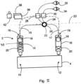
- Fig. 3 shows an example of a drive assembly 2, wherein a single position sensor "P" (as a position pickup unit 40) is within each actuator 14 and 16. This would deliver the same redundancy as in the arrangement of Fig. 1 .
- Fig. 4 shows a further example of a drive assembly 2, wherein a redundant position sensor "P/P" (as a position pickup unit 40) is within each actuator 14 and 16.
- Fig. 5 shows a further optional arrangement of a drive assembly 2, wherein one redundant position sensor "P/P" is located in only one of the two actuators 14 and 16.
- the aircraft 8 has a left-hand wing-half 44 and a right-hand wing-half 46, which both comprise an outboard flap 48 and an inboard flip 50.
- the flaps 48 and 50 are provided in the form of the movable flow body 4 and each of the flaps 48 and 50 is driven by a dedicated drive assembly 2.
- the plurality of drive assemblies 2 constitute a drive system 3.
- the drive system 3 in combination with the flaps 48 and 50 constitute a (trailing-edge) high lift system 52.
Landscapes
- Engineering & Computer Science (AREA)
- Aviation & Aerospace Engineering (AREA)
- Automation & Control Theory (AREA)
- Mechanical Engineering (AREA)
- Transmission Devices (AREA)
- Retarders (AREA)
Abstract
Description
- The invention relates to a drive assembly for driving a movable flow body of an aircraft movable, a drive system for a plurality of movable flow bodies, a high lift system having such a drive system, a wing, and an aircraft.
- For increasing the lift coefficient of a wing of an aircraft, high-lift systems are known. These often include trailing edge flaps and movable leading-edge devices, which are selectively operable. For example, they are usually activated during takeoff and landing, i.e., moved from a retracted into an extended position.
- Trailing-edge flaps of high-lift systems in commercial passenger aircraft are often driven by a single drive unit located in the center of the aircraft's fuselage, wherein the drive unit is often referred to as a "power control unit" (PCU). The PCU often comprises two motors acting in parallel, the drive power of which is transmitted to the respective transmission shaft system via a differential, whereby several drive types exist. A left hand and a right-hand transmission shaft system extend from the PCU into the left- or right-hand wing and are and are coupled with local mechanical actuating devices at corresponding flap stations. Commonly, these actuators are often provided in the form of linear ball screw actuators or geared rotary actuators. At the outboard ends of the transmission shaft systems, safety brakes are often provided, which are often referred to as "wing tip brakes" (WTB). Commonly, high-lift systems are controlled and monitored through a control computer, such as a "Slat Flap Control Computer" (SFCC).
- Starting from the PCU, synchronization between individual flaps of a left and a right wing as well as between the flaps of a wing is provided via the transmission shaft systems. Due to their lengths and course inside the wings, often a large number of bearings, cardan joints and couplings are provided.
- For providing different extension movements of inboard and outboard flaps, it is known to include an active differential gear box between inboard and outboard flaps between two coupled transmission shaft sections of the same wing. However, this is a complex component to enable differential flap settings function in a centralized system.
-
EP 1 462 361 B1US Pat. US 7,048,234 B2 show a flap system on the wing of a fixed-wing aircraft in which system flaps are coupled to synchronized wing-internal individual drives. - It is an object of the invention to propose an alternate drive system or drive assembly, which allows differential flap settings with a reduced mechanical complexity.
- This object is met by a drive assembly for driving a movable flow body of an aircraft having the features of
independent claim 1. Advantageous embodiments and further improvements may be gathered from the subclaims and the following description. - A drive assembly for driving a movable flow body of an aircraft is proposed, comprising an electric motor having a first set of windings and a second set of windings, wherein the first set and the second set are independent from each other, a first motor control electronics unit coupled with the first set of windings and a control computer, a second motor control electronics unit coupled with the second set of windings and the control computer, a first actuator couplable with a first section of the movable flow body, a second actuator couplable with a second section of the same movable flow body, a first transmission shaft, and a second transmission shaft, wherein the transmission shafts each have a first end and a second end, wherein the electric motor is coupled with the first ends of the first transmission shaft and of the second transmission shaft to rotate both transmission shafts synchronously, wherein the second end of the first transmission shaft is coupled with the first actuator, wherein the second end of the second transmission shaft is coupled with the second actuator, and wherein the drive assembly is designed to selectively move and hold the movable flow body into a plurality of extended positions and a retracted position relative to a fixed structural component of the aircraft by selectively moving and holding the first actuator and the second actuator.
- The drive assembly according to the invention relates to an apparatus or a group of components that are associated with a single movable flow body. This means, that one drive assembly is associated with and capable of driving one dedicated flow body. Using a plurality of these drive assemblies allows to move a plurality of flow bodies on a wing half or on two wing halves of the respective aircraft independently. A central drive unit and a set of transmission shaft systems are thus not required.
- The movable flow body may preferably be a trailing-edge component on a wing of an aircraft, which is extendable relative to a fixed wing part of the aircraft. However, it may also refer to a leading-edge component of a wing.
- The movable flow body may comprise a first section and a second section arranged at a spanwise distance to each other. The sections are couplable with one of the first actuator and the second actuator each. Thus, the flow body may be driven through both synchronously moving actuators on a course that is defined by a support of the movable flow body. For example, by moving the flow body further away from the fixed wing part of the aircraft, i.e., into an extended position, the wing surface area as well as the camber increases. Moving the flow body into the retracted position leads to a clean wing.
- The electric motor is preferably realized in the form of a DC motor. Preferably, it is a brushless motor. It may, for example, be supplied with electrical power from at least one high voltage DC bus (HVDC). Due to the use of two separate and independent sets of windings, the electric motor is a redundant device. Each of the sets of windings is connected to a dedicated motor control electronics (MCE) unit. It is feasible to connect both MCE units to two independent HVDC buses. For example, one of the MCE units may be connected to a first HVDC bus, the other one of the MCE units may be connected to a second HVDC bus. Also, both MCE units may be permanently or selectively be connected to both the first and the second HVDC bus. Hence, the function of moving the flow body can be maintained even if one HVDC bus and/or one MCE unit and/or one set of windings experiences a restricted function.
- In addition to providing a level of redundancy, the use of redundant windings may also improve the efficiency and performance of the electric motor. Because each set of windings can be controlled independently, the electric motor can be operated in a way that optimizes its efficiency and power output. This may be particularly useful for operating the electric motor at high speeds or under heavy loads.
- An MCE unit may be understood as a device that is used to control the speed and direction of the electric motor. It may comprise a power circuit, which provides the necessary power to the electric motor, and a control circuit, which processes control signals and adjusts the power to the electric motor accordingly. The design of the power circuit may depend on a number of factors, including the type of electric motor being used, the power requirements, and the specific application. It may comprise a switching device, such as a transistor or a MOSFET, which is used to control the flow of current to the electric motor. In addition, it may comprise an overcurrent protection device and filtering components.
- Both MCE units are connected to the control computer and receive signals to initiate an operation of the electric motor. The MCE unit, in particular its control circuit, may also include various sensors and feedback mechanisms to monitor the performance of the electric motor and ensure its proper operation. Furthermore, the MCE units may also comprise control and monitoring logics for local monitoring tasks. Also, they may act as remote data concentrators if sensors (see further below) are connected to the MCE units. In this case, the MCE units may deliver the data to a data network, to which they may then connected.
- The MCE units may be arranged near the respective electric motor. However, they may also be placed in a further distance from the electric motor, such as in a flap-track-fairing.
- The actuators are coupled to the electric motor through the first or the second transmission shaft. They are preferably designed to transform a rotary motion of the respective transmission shaft into a linear motion to drive the associated section of the flow body. For example, the actuators may comprise a linear actuator, such as a ball screw actuator. However, they may also comprise a rotary actuator, such as a geared rotary actuator, that provides a rotary motion for swiveling a lever or a similar component. Due to the connection of both actuators to the electric motor, they are driven synchronously and thus always provide the same amount of motion.
- Both transmission shafts are used for transferring mechanical power from the electric motor to the respective actuator. Each actuator is thus associated with one of the transmission shafts. The electric motor may be arranged in a fixed wing part of the respective aircraft substantially in the center between both sections and the transmission shafts extends from one side of the electric motor to the respective actuator.
- The transmission shafts are provided in the form of short, isolated shafts, which exclusively extend from the electric motor to the respective actuator. They may be coupled to each other through a shaft of the motor. The first end of both transmission shafts is connected to the motor shaft, while the second end of both transmission shafts is connected to the respective actuator. This clearly distinguishes from above-mentioned transmission shaft systems, where the transmission shaft is created by a plurality of shaft sections extending through substantially the whole wing in a spanwise direction.
- Compared to a centralized high lift system having a PCU, the drive assembly according to the invention neither has a mechanical link between the left-hand wing half and the right-hand wing half and also not between movable flow bodies on the same wing half. For an aircraft, instead of the PCU several such drive assemblies would be required to move all desired flow bodies, such as trailing-edge flaps, and would provide the capability of performing a differential flap setting function by design, for instance to provide lateral trim. As a further key feature the drive assembly according to the invention still maintains a mechanical link between two driven support stations of a single flap or another movable flow body to synchronize the movement of the two actuators to avoid force fighting on the movable flow body.
- The drive assembly according to the invention has multiple advantages. For example, a better physical integration feasibility is possible due to fewer parts and the eliminated transmission shaft routing between flaps and from the center of the aircraft fuselage to inboard flaps. Fewer parts result in a weight saving on system level, an installation time saving and in lower drag of the system reducing the necessary power to operate the high lift system. Furthermore, the architecture provides the capability for the differential flap setting function by design.
- In an advantageous embodiment, the first transmission shaft and the second transmission shaft are designed as flexible shafts. A flexible shaft is a type of mechanical component that is designed to transmit rotary motion from one point to another while being able to bend or flex along its length. This allows to accommodate changes in the alignment or orientation of the two points. The electric motor may comprise a motor shaft that protrudes from two axial sides of the electric motor. One of the transmission shafts may be connected to the motor shaft on one axial side, the other one of the transmission shafts may be connected to the motor shaft on other axial side. Both transmission shafts may extend along a straight or non-straight course to the respective actuator. Hence, a complex arrangement of rigid transmission shafts in combination with axial and rotary joints is not required.
- In an advantageous embodiment, at least one position pickup unit is coupled with at least one of the transmission shafts and/or the electric motor, wherein the at least one position pickup unit is coupled with the control computer. Coupling the position pickup unit with the control computer may be conducted either directly or through the MCE units. The position pickup units may either provide an analogue or digital signal. For example, both the transmission shafts may be equipped with a separate position pickup unit, i.e., a first position pickup unit and a second position pickup unit. They may also be referred to as position sensors, which are devices used to monitor the position of the transmission shafts and, consequently, of the respective actuator and the movable flow body. Instead and/or in addition thereto, the electric motor may be coupled with a position pickup unit, which monitors the rotational position of the electric motor. The at least one position pickup unit comprises a sensor, such as a potentiometer or a position encoder, and a device that sends position information to the control computer. The measured position information is used to ensure that the respective flow body is placed in the desired position for take-off and landing, and to provide feedback for the pilots or automatic flight control system.
- In an advantageous embodiment, at least one position pickup unit is coupled with at least one of the first and second actuators; and the at least one position pickup unit is coupled with the control computer. The term "coupled with" may also mean "arranged at", "arranged on", "located inside" and the like. The at least one position pickup unit (which may also be referred to as position sensor) may for example be a linear position sensor within a linear actuator or a rotary sensor within a rotary actuator. The coupling with the control computer is as defined above. If a position pickup unit is coupled with or arranged in at least one of the first and second actuators, this may mean that an actuator comprises the at least one position sensor and that, for example the position sensor is located inside the actuator.
- In an advantageous embodiment, the at least one position pickup unit is a single position sensor. Thus, the arrangement can be a single position sensor in each actuator. According to an example, the arrangement can also be one single position sensor in only one of the first and second actuators.
- In an advantageous embodiment, the at least one position pickup unit is a redundant position sensor.
- According to an example, one of the first or the second actuators may be coupled with a redundant position sensor. That is, only one of the actuators comprises one redundant position sensor.
- According to a further example, a redundant position sensor is provided in each actuator, i.e. both the first and the second actuators each are coupled with a position pickup unit which is a redundant position sensor. A "redundant position sensor" means that there are two position sensors of which each one provides its signal, for example via one connected signal channel.
- It is also conceivable that one actuator comprises a single position sensor and the other actuator comprises a redundant position sensor.
- All arrangements with a position pickup unit coupled with at least one of the actuators have the advantageous effect of measuring directly the actuator position instead of measuring the transmission position and thus, an even higher accuracy can be achieved.
- In an advantageous embodiment, the first actuator and/or the second actuator comprises a linear ball screw actuator. Thus, the actuators use a ball screw mechanism to convert rotary motion delivered by the respective transmission shaft into a linear motion. Such a type of actuator may comprise a ball screw that is rotatably supportable in a fixed wing part and driven by the respective transmission shaft. A nut engages with the ball screw and is mechanically couplable with the movable flow body at its respective section. The nut will travel along the longitudinal extension of the ball screw and is thus a linear actuator. This design leads to a high precision motion and a superior reliability.
- In an advantageous embodiment, the first actuator and/or the second actuator comprises a geared rotary actuator. Thus, the actuators comprise a gear train having a plurality of gears, wherein the gear train is driven through the respective transmission shaft. The gears may provide a reduction ratio. The geared rotary actuator may comprise a rotating element, which is coupled to a lever, which in turn is coupled to the respective section of the movable flow body. Such an actuator is also commonly used in aircraft and is able to provide a precise and reliable control of the movable flow body.
- In an advantageous embodiment, the first actuator and/or the second actuator comprises a no-back device and/or a power-off brake adapted to prevent the flow body from moving when the electric motor is stopped. Such a no-back device or power-off brake is a mechanical component that is used to prevent the movable flow body from moving when the electric motor that drives it is stopped. A no-back device typically consists of a brake or other mechanical mechanism that at least engages when the power is turned off or when it is not actively disengaged. The no-back device shall engage the brake in a retract position, such that the electric motor needs to pull actively against the brake and shall disengage in an extend direction, such that the electric motor only drives against the air loads.
- In an advantageous embodiment, the electric motor may comprise a power-off brake to arrest the drive assembly before and after a drive sequence. Thus, the first and second transmission shafts and, consequently, the first and second actuator, will be arrested when the electric motor is stopped. The power-off brake of the electric motor may be provided in addition to no-back devices or power-off brakes on the transmission shafts mentioned above.
- In an advantageous embodiment, the actuators comprise a rotary input having a rotational axis transverse to a rotational axis of the electric motor. For example, the electric motor may be aligned with a spanwise axis of the wing inside the fixed wing part. Its integration is thus very space efficient. The flexible transmission shafts allow to transfer the rotary motion from the spanwise rotational axis to a rotational axis that may be aligned substantially parallel to the longitudinal axis of the aircraft or perpendicular to the spanwise axis.
- At the second ends of the transmission shafts, i.e. at the rotary inputs, a bevel gear stage may be provided in the actuators to not only route the rotational motion from a spanwise to a chordwise direction via a flexible shaft, but by a combination of a flexible shaft bending and the gear stage in the respective actuator.
- In an additional option, the rotational axis of the rotary input and the rotational axis of the electric motor enclose an angle in a range of 45° to 135°. The flexible transmission shafts allow the transfer of rotational motion in this angle range by bending. The angle range reflects the alignment of the electric motor parallel to the spanwise axis and the rotary input of the actuators parallel to the longitudinal axis or transverse to the spanwise axis with a swept wing.
- The invention further relates to a drive system, comprising a plurality of drive assemblies according to the above, wherein the drive assemblies are independent from each other, such that individual flow bodies are movable independently from each other. For example, the drive system may comprise an even number of drive assemblies, in order to provide a symmetrical arrangement on two wing halves. In particular, the drive system may comprise four drive assemblies for moving four movable flow bodies, in particular trailing-edge flaps.
- The invention also relates to a high lift system, comprising at least one drive system according to the above and/or at least one drive assembly according to the explanation further above and at least one movable flow body coupled with the at least one drive system and/or the at least one drive assembly.
- In an additional option, the high lift system is a trailing-edge flap high lift system.
- Still further, the invention relates to a wing, comprising at least one such high lift system.
- Lastly, the invention relates to an aircraft, comprising at least one wing according to the above, and/or at least one high lift system according to the above and/or at least one drive system according to the above and/or at least one drive assembly according to the above.
- In the following, the attached drawings are used to illustrate exemplary embodiments in more detail. The illustrations are schematic and not to scale. Identical reference numerals refer to identical or similar elements. They show:
-
Fig. 1 shows a schematic view of a drive assembly. -
Fig. 2 shows a schematic view of an aircraft having a plurality of flaps and associated drive assemblies for driving the flaps. -
Figs. 3 ,4 and5 show further schematic views of a drive assembly. - Detailed description of exemplary embodiments
-
Fig. 1 shows adrive assembly 2 for driving amovable flow body 4, which is shown in form of a trailing-edge flap. Such amovable flow body 4 is movably supported on a fixedwing part 6 of anaircraft 8 shown inFig. 2 . Thedrive assembly 2 is exclusively associated with asingle flow body 4, such that for moving a plurality offlow bodies 4,several drive assemblies 2 are required. - The
movable flow body 4 comprises afirst section 10 and asecond section 12, i.e., positional regions, which are arranged at a distance to each other in a spanwise direction. Afirst actuator 14 is coupled with theflow body 4 in thefirst section 10. Asecond actuator 16 is coupled with thesecond section 12 of themovable flow body 4. - Exemplarily, both
actuators load sensor 18 as well as a no-back device 20, which is only schematically shown. These transform a rotational motion into a translational motion. - Both
actuators electric motor 22, which comprises a first set ofwindings 24 and a second set ofwindings 26, which are independent from each other. Bothwindings unit first MCE unit 28 is coupled with a firstelectrical power supply 32 and thesecond MCE unit 30 is coupled with a secondelectrical power supply 34. Both power supplies are redundant. They may be realized in the form of a high voltage DC bus or an AC bus each. Hence, theelectric motor 22 is supplied with power from two independent power supplies and allows a safe operation even if one of the components, i.e., a set ofwindings MCE unit - The
electric motor 22 may or may not comprise an additional power-off brake. - To transfer the mechanical power from the
electric motor 22 to thefirst actuator 14, afirst transmission shaft 15 is provided. In analogy, mechanical power is transferred to thesecond actuator 16 through asecond transmission shaft 17. Bothtransmission shafts - Exemplarily, the
electric motor 22 comprises arotational axis 23, which is aligned substantially parallel to aspanwise axis 25 of the respective wing of theaircraft 8. Theactuators rotary input 19, which is exemplarily arranged parallel to the longitudinal axis x of theaircraft 8. Thus, the ends of thetransmission shafts - A
first control computer 36 and asecond control computer 38 are coupled with one of theMCE units electric motor 22. Bothcontrol computers electric motor 22 is coupled with aposition pickup unit 40, which in turn is exemplarily connected to theMCE units control computers load sensors 18 are exemplarily connected to theMCE units sensors - An
input device 42, such as a flight lever, is exemplarily connected to theflight control computers flow body 4, initiating operation of theelectric motor 22 and to monitor the position throughposition pickup unit 40 as well as the loads on theactuators load sensors 18. -
Figs. 3 ,4 and5 show further examples of adrive assembly 2 for driving amovable flow body 4, wherein the position pickup unit 40 (position sensor) is moved into theactuators -
Fig. 3 shows an example of adrive assembly 2, wherein a single position sensor "P" (as a position pickup unit 40) is within eachactuator Fig. 1 . -
Fig. 4 shows a further example of adrive assembly 2, wherein a redundant position sensor "P/P" (as a position pickup unit 40) is within eachactuator -
Fig. 5 shows a further optional arrangement of adrive assembly 2, wherein one redundant position sensor "P/P" is located in only one of the twoactuators - The
aircraft 8 has a left-hand wing-half 44 and a right-hand wing-half 46, which both comprise anoutboard flap 48 and aninboard flip 50. Theflaps movable flow body 4 and each of theflaps dedicated drive assembly 2. The plurality ofdrive assemblies 2 constitute adrive system 3. Thedrive system 3 in combination with theflaps high lift system 52. -
- 2
- drive assembly
- 3
- drive system
- 4
- flow body
- 6
- fixed wing part
- 8
- aircraft
- 10
- first section
- 12
- second section
- 14
- first actuator
- 15
- first transmission shaft
- 16
- second actuator
- 17
- second transmission shaft
- 18
- load sensor
- 19
- rotary input
- 20
- no-back device
- 22
- electric motor
- 23
- spanwise axis
- 24
- first set of windings
- 26
- second set of windings
- 28
- first MCE unit
- 30
- second MCE unit
- 32
- first DC bus
- 34
- second DC bus
- 36
- first control computer
- 38
- second control computer
- 40
- position pickup unit
- 42
- input device
- 44
- left-hand wing half
- 46
- right-hand wing half
- 48
- outboard flap
- 50
- inboard flap
- 52
- high-lift system
- x
- longitudinal axis
Claims (15)
- Drive assembly (2) for driving a movable flow body (4, 48, 50) of an aircraft (8), comprising:- an electric motor (22) having a first set of windings (24) and a second set of windings (26), wherein the first set (24) and the second set (26) are independent from each other,- a first motor control electronics unit (28) coupled with the first set of windings (24) and a control computer (36, 38),- a second motor control electronics unit (30) coupled with the second set of windings (26) and the control computer (36, 38),- a first actuator (14) couplable with a first section (10) of the movable flow body (4, 48, 50),- a second actuator (16) couplable with a second section (12) of the same movable flow body (4, 48, 50),- a first transmission shaft (15), and- a second transmission shaft (17),wherein the transmission shafts (15, 17) each have a first end and a second end,wherein the electric motor (22) is coupled with the first ends of the first transmission shaft (15) and of the second transmission shaft (17) to rotate both transmission shafts (15, 17) synchronously,wherein the second end of the first transmission shaft (15) is coupled with the first actuator (14),wherein the second end of the second transmission shaft (17) is coupled with the second actuator (16), andwherein the drive assembly (2) is designed to selectively move and hold the movable flow body (4, 48, 50) into a plurality of extended positions and a retracted position relative to a fixed structural component (6) of the aircraft (8) by selectively moving and holding the first actuator (14) and the second actuator (16).
- Drive assembly (2) of claim 1,
wherein the first transmission shaft (15) and the second transmission shaft (17) are designed as flexible shafts. - Drive assembly (2) of claim 1 or 2,wherein at least one position pickup unit (40) is coupled with at least one of the transmission shafts (15, 17) and/or the electric motor (22), andwherein the at least one position pickup unit (40) is coupled with the control computer (36, 38).
- Drive assembly (2) of claim 1 or 2,wherein at least one position pickup unit (40) is coupled with at least one of the first and second actuators (14, 16); andwherein the at least one position pickup unit (40) is coupled with the control computer (36, 38).
- Drive assembly (2) of claim 4,
wherein the at least one position pickup unit (40) is a single position sensor. - Drive assembly (2) of claim 4,
wherein the at least one position pickup unit (40) is a redundant position sensor. - Drive assembly (2) of any of the preceding claims,
wherein the first actuator (14) and/or the second actuator (16) comprises a linear ball screw actuator. - Drive assembly (2) of any of the claims 1 to 3,
wherein the first actuator (14) and/or the second actuator (16) comprises a geared rotary actuator. - Drive assembly (2) of any of the preceding claims,
wherein the first actuator (14) and/or the second actuator (16) comprises a no-back device (20) and/or a power-off brake adapted to prevent the flow body (4, 48, 50) from moving when the electric motor (22) is stopped. - Drive assembly (2) of any of the preceding claims,
wherein the electric motor (22) comprises a power-off brake to arrest the drive assembly (2) before and after a drive sequence. - Drive assembly (2) of claim 2,wherein the actuators (14, 16) comprise a rotary input (19) having a rotational axis transverse to a rotational axis of the electric motor (22); andwherein the rotational axis of the rotary input (19) and the rotational axis of the electric motor (22) enclose an angle in a range of 45° to 135°.
- Drive system (3), comprising a plurality of drive assemblies (2) according to any of the preceding claims,
wherein the drive assemblies (2) are independent from each other, such that individual flow bodies (4, 48, 50) are movable independently from each other. - High lift system (52), comprising at least one drive system (3) according to claim 13 and/or at least one drive assembly (2) according to any of the claims 1 to 12 and at least one movable flow body (4, 48, 50) coupled with the at least one drive system (3) and/or the at least one drive assembly (2); and
wherein the high lift system (52) is a trailing-edge flap high lift system (52). - Wing (44, 46), comprising at least one high lift system (52) of claim 13.
- Aircraft (8), comprising at least one wing (44, 46) of claim 14 and/or at least one high lift system (52) of claim 13 and/or at least one drive system (3) of claim 12 and/or at least one drive assembly (2) of any of the claims 1 to 11.
Applications Claiming Priority (1)
| Application Number | Priority Date | Filing Date | Title |
|---|---|---|---|
| EP23151786.3A EP4400418A1 (en) | 2023-01-16 | 2023-01-16 | Drive assembly for driving a movable flow body of an aircraft |
Publications (2)
| Publication Number | Publication Date |
|---|---|
| EP4400419A1 true EP4400419A1 (en) | 2024-07-17 |
| EP4400419B1 EP4400419B1 (en) | 2026-02-04 |
Family
ID=84981329
Family Applications (2)
| Application Number | Title | Priority Date | Filing Date |
|---|---|---|---|
| EP23151786.3A Withdrawn EP4400418A1 (en) | 2023-01-16 | 2023-01-16 | Drive assembly for driving a movable flow body of an aircraft |
| EP23218975.3A Active EP4400419B1 (en) | 2023-01-16 | 2023-12-21 | Drive assembly for driving a movable flow body of an aircraft |
Family Applications Before (1)
| Application Number | Title | Priority Date | Filing Date |
|---|---|---|---|
| EP23151786.3A Withdrawn EP4400418A1 (en) | 2023-01-16 | 2023-01-16 | Drive assembly for driving a movable flow body of an aircraft |
Country Status (3)
| Country | Link |
|---|---|
| US (1) | US12391367B2 (en) |
| EP (2) | EP4400418A1 (en) |
| CN (1) | CN118343287A (en) |
Families Citing this family (2)
| Publication number | Priority date | Publication date | Assignee | Title |
|---|---|---|---|---|
| DE102024136724A1 (en) * | 2024-12-09 | 2026-06-11 | Liebherr-Aerospace Lindenberg Gmbh | Control system for an aircraft and aircraft |
| DE102025000268A1 (en) | 2025-01-23 | 2026-07-23 | Airbus Operations Gmbh | Drive arrangement for powering a movable flow device of an aircraft |
Citations (5)
| Publication number | Priority date | Publication date | Assignee | Title |
|---|---|---|---|---|
| US6824099B1 (en) * | 2003-07-10 | 2004-11-30 | The Boeing Company | Brake systems for aircraft wing flaps and other control surfaces |
| US7048234B2 (en) | 2003-03-27 | 2006-05-23 | Airbus Deutschland Gmbh | Adaptive flap and slat drive system for aircraft |
| US20060289696A1 (en) * | 2005-06-27 | 2006-12-28 | Honeywell International, Inc. | Electric flight control surface actuation system for aircraft flaps and slats |
| US20130026287A1 (en) * | 2011-07-28 | 2013-01-31 | Airbus Operations (Sas) | Method And Device For Detecting An Uncontrolled Movement Of An Aircraft Control Surface |
| US20200156766A1 (en) * | 2018-11-16 | 2020-05-21 | Bombardier Inc. | High-lift actuation system having independent actuation control |
Family Cites Families (11)
| Publication number | Priority date | Publication date | Assignee | Title |
|---|---|---|---|---|
| US3015936A (en) * | 1957-06-03 | 1962-01-09 | Curtiss Wright Corp | Thrust reversers |
| SE392083B (en) * | 1975-05-16 | 1977-03-14 | Skf Nova Ab | STEERING MECHANISM, MAINLY INTENDED FOR BATTERY |
| US4434389A (en) * | 1980-10-28 | 1984-02-28 | Kollmorgen Technologies Corporation | Motor with redundant windings |
| US6020711A (en) * | 1998-03-05 | 2000-02-01 | The United States Of America As Represented By The Secretary Of The Air Force | Multiple winding channel, magnetic coupling-alterable reluctance electrical machines and their fault tolerant control |
| US6755375B2 (en) * | 2002-10-22 | 2004-06-29 | The Boeing Company | Method and apparatus for controlling aircraft devices with multiple actuators |
| US6924574B2 (en) * | 2003-05-30 | 2005-08-02 | Wisconsin Alumni Research Foundation | Dual-rotor, radial-flux, toroidally-wound, permanent-magnet machine |
| DE102008022092A1 (en) * | 2008-05-05 | 2009-11-19 | Airbus Deutschland Gmbh | Fault-tolerant control system for adjusting the flaps of an aircraft with adjustable kinematics with a fixed axis of rotation |
| US9303743B2 (en) * | 2013-12-16 | 2016-04-05 | Honeywell International Inc. | Ball screw actuator including an axial soft stop |
| US10892672B2 (en) * | 2016-03-30 | 2021-01-12 | Advanced Magnet Lab, Inc. | Dual-rotor synchronous electrical machines |
| DE102016015383A1 (en) * | 2016-12-22 | 2018-06-28 | Liebherr-Aerospace Lindenberg Gmbh | Actuator in a landing gear system of an aircraft |
| US11715948B2 (en) * | 2021-02-09 | 2023-08-01 | The Boeing Company | Fault-tolerant power distribution in a vehicle |
-
2023
- 2023-01-16 EP EP23151786.3A patent/EP4400418A1/en not_active Withdrawn
- 2023-12-21 EP EP23218975.3A patent/EP4400419B1/en active Active
-
2024
- 2024-01-12 US US18/411,179 patent/US12391367B2/en active Active
- 2024-01-16 CN CN202410062887.0A patent/CN118343287A/en active Pending
Patent Citations (6)
| Publication number | Priority date | Publication date | Assignee | Title |
|---|---|---|---|---|
| US7048234B2 (en) | 2003-03-27 | 2006-05-23 | Airbus Deutschland Gmbh | Adaptive flap and slat drive system for aircraft |
| EP1462361B1 (en) | 2003-03-27 | 2006-06-28 | Airbus Deutschland GmbH | Airplane high lift surface drive system |
| US6824099B1 (en) * | 2003-07-10 | 2004-11-30 | The Boeing Company | Brake systems for aircraft wing flaps and other control surfaces |
| US20060289696A1 (en) * | 2005-06-27 | 2006-12-28 | Honeywell International, Inc. | Electric flight control surface actuation system for aircraft flaps and slats |
| US20130026287A1 (en) * | 2011-07-28 | 2013-01-31 | Airbus Operations (Sas) | Method And Device For Detecting An Uncontrolled Movement Of An Aircraft Control Surface |
| US20200156766A1 (en) * | 2018-11-16 | 2020-05-21 | Bombardier Inc. | High-lift actuation system having independent actuation control |
Also Published As
| Publication number | Publication date |
|---|---|
| US20240239476A1 (en) | 2024-07-18 |
| EP4400419B1 (en) | 2026-02-04 |
| US12391367B2 (en) | 2025-08-19 |
| EP4400418A1 (en) | 2024-07-17 |
| CN118343287A (en) | 2024-07-16 |
Similar Documents
| Publication | Publication Date | Title |
|---|---|---|
| US7048234B2 (en) | Adaptive flap and slat drive system for aircraft | |
| EP4400419B1 (en) | Drive assembly for driving a movable flow body of an aircraft | |
| US7556224B2 (en) | Distributed flight control surface actuation system | |
| US9190942B2 (en) | Near synchronous controlled induction motor drive actuation system | |
| US8814085B2 (en) | Fault-tolerant actuating system for adjusting flaps of an aircraft, comprising adjustment kinematics with a fixed pivot, and a method for monitoring an actuating system | |
| US7549605B2 (en) | Electric flight control surface actuation system for aircraft flaps and slats | |
| US11242131B2 (en) | High-lift actuation system having centralized inboard actuation control and independent outboard actuation control | |
| US20200156766A1 (en) | High-lift actuation system having independent actuation control | |
| EP2851284B1 (en) | Variable camber flap system and method | |
| CN102458995B (en) | aircraft with high lift system | |
| US11174006B2 (en) | High-lift actuation system with clutch architecture | |
| CN111439370B (en) | High lift system and flap control method | |
| CN114954904A (en) | Foldable wing, aircraft having the same, and folding control method | |
| US9809326B2 (en) | Method for adjusting the play in a high-lift system of an aircraft | |
| CN111516857A (en) | Flap distributed driving system | |
| EP4733188A1 (en) | Drive assembly for driving a movable flow device of an aircraft | |
| EP4491510A1 (en) | Single flap drive system for decentralized flap architectures |
Legal Events
| Date | Code | Title | Description |
|---|---|---|---|
| PUAI | Public reference made under article 153(3) epc to a published international application that has entered the european phase |
Free format text: ORIGINAL CODE: 0009012 |
|
| STAA | Information on the status of an ep patent application or granted ep patent |
Free format text: STATUS: THE APPLICATION HAS BEEN PUBLISHED |
|
| AK | Designated contracting states |
Kind code of ref document: A1 Designated state(s): AL AT BE BG CH CY CZ DE DK EE ES FI FR GB GR HR HU IE IS IT LI LT LU LV MC ME MK MT NL NO PL PT RO RS SE SI SK SM TR |
|
| STAA | Information on the status of an ep patent application or granted ep patent |
Free format text: STATUS: REQUEST FOR EXAMINATION WAS MADE |
|
| 17P | Request for examination filed |
Effective date: 20250110 |
|
| GRAP | Despatch of communication of intention to grant a patent |
Free format text: ORIGINAL CODE: EPIDOSNIGR1 |
|
| STAA | Information on the status of an ep patent application or granted ep patent |
Free format text: STATUS: GRANT OF PATENT IS INTENDED |
|
| RIC1 | Information provided on ipc code assigned before grant |
Ipc: B64C 13/50 20060101AFI20250716BHEP Ipc: B64D 45/00 20060101ALI20250716BHEP Ipc: B64C 9/16 20060101ALN20250716BHEP |
|
| INTG | Intention to grant announced |
Effective date: 20250730 |
|
| GRAS | Grant fee paid |
Free format text: ORIGINAL CODE: EPIDOSNIGR3 |
|
| GRAA | (expected) grant |
Free format text: ORIGINAL CODE: 0009210 |
|
| STAA | Information on the status of an ep patent application or granted ep patent |
Free format text: STATUS: THE PATENT HAS BEEN GRANTED |
|
| AK | Designated contracting states |
Kind code of ref document: B1 Designated state(s): AL AT BE BG CH CY CZ DE DK EE ES FI FR GB GR HR HU IE IS IT LI LT LU LV MC ME MK MT NL NO PL PT RO RS SE SI SK SM TR |
|
| REG | Reference to a national code |
Ref country code: CH Ref legal event code: F10 Free format text: ST27 STATUS EVENT CODE: U-0-0-F10-F00 (AS PROVIDED BY THE NATIONAL OFFICE) Effective date: 20260204 Ref country code: GB Ref legal event code: FG4D |
|
| REG | Reference to a national code |
Ref country code: DE Ref legal event code: R096 Ref document number: 602023011594 Country of ref document: DE |
|
| REG | Reference to a national code |
Ref country code: IE Ref legal event code: FG4D |
|
| REG | Reference to a national code |
Ref country code: NL Ref legal event code: MP Effective date: 20260204 |
|
| PG25 | Lapsed in a contracting state [announced via postgrant information from national office to epo] |
Ref country code: RS Free format text: LAPSE BECAUSE OF FAILURE TO SUBMIT A TRANSLATION OF THE DESCRIPTION OR TO PAY THE FEE WITHIN THE PRESCRIBED TIME-LIMIT Effective date: 20260504 |
|
| PG25 | Lapsed in a contracting state [announced via postgrant information from national office to epo] |
Ref country code: ES Free format text: LAPSE BECAUSE OF FAILURE TO SUBMIT A TRANSLATION OF THE DESCRIPTION OR TO PAY THE FEE WITHIN THE PRESCRIBED TIME-LIMIT Effective date: 20260204 |
|
| PG25 | Lapsed in a contracting state [announced via postgrant information from national office to epo] |
Ref country code: PL Free format text: LAPSE BECAUSE OF FAILURE TO SUBMIT A TRANSLATION OF THE DESCRIPTION OR TO PAY THE FEE WITHIN THE PRESCRIBED TIME-LIMIT Effective date: 20260204 |
|
| PG25 | Lapsed in a contracting state [announced via postgrant information from national office to epo] |
Ref country code: GR Free format text: LAPSE BECAUSE OF FAILURE TO SUBMIT A TRANSLATION OF THE DESCRIPTION OR TO PAY THE FEE WITHIN THE PRESCRIBED TIME-LIMIT Effective date: 20260505 |
|
| REG | Reference to a national code |
Ref country code: LT Ref legal event code: MG9D |
|
| PG25 | Lapsed in a contracting state [announced via postgrant information from national office to epo] |
Ref country code: LT Free format text: LAPSE BECAUSE OF FAILURE TO SUBMIT A TRANSLATION OF THE DESCRIPTION OR TO PAY THE FEE WITHIN THE PRESCRIBED TIME-LIMIT Effective date: 20260204 |
|
| PG25 | Lapsed in a contracting state [announced via postgrant information from national office to epo] |
Ref country code: NO Free format text: LAPSE BECAUSE OF FAILURE TO SUBMIT A TRANSLATION OF THE DESCRIPTION OR TO PAY THE FEE WITHIN THE PRESCRIBED TIME-LIMIT Effective date: 20260504 |
|
| PG25 | Lapsed in a contracting state [announced via postgrant information from national office to epo] |
Ref country code: AT Free format text: LAPSE BECAUSE OF FAILURE TO SUBMIT A TRANSLATION OF THE DESCRIPTION OR TO PAY THE FEE WITHIN THE PRESCRIBED TIME-LIMIT Effective date: 20260204 Ref country code: FI Free format text: LAPSE BECAUSE OF FAILURE TO SUBMIT A TRANSLATION OF THE DESCRIPTION OR TO PAY THE FEE WITHIN THE PRESCRIBED TIME-LIMIT Effective date: 20260204 Ref country code: SE Free format text: LAPSE BECAUSE OF FAILURE TO SUBMIT A TRANSLATION OF THE DESCRIPTION OR TO PAY THE FEE WITHIN THE PRESCRIBED TIME-LIMIT Effective date: 20260204 |
|
| REG | Reference to a national code |
Ref country code: AT Ref legal event code: MK05 Ref document number: 1883890 Country of ref document: AT Kind code of ref document: T Effective date: 20260204 |
|
| PG25 | Lapsed in a contracting state [announced via postgrant information from national office to epo] |
Ref country code: HR Free format text: LAPSE BECAUSE OF FAILURE TO SUBMIT A TRANSLATION OF THE DESCRIPTION OR TO PAY THE FEE WITHIN THE PRESCRIBED TIME-LIMIT Effective date: 20260204 |
|
| PG25 | Lapsed in a contracting state [announced via postgrant information from national office to epo] |
Ref country code: PT Free format text: LAPSE BECAUSE OF FAILURE TO SUBMIT A TRANSLATION OF THE DESCRIPTION OR TO PAY THE FEE WITHIN THE PRESCRIBED TIME-LIMIT Effective date: 20260605 Ref country code: IS Free format text: LAPSE BECAUSE OF FAILURE TO SUBMIT A TRANSLATION OF THE DESCRIPTION OR TO PAY THE FEE WITHIN THE PRESCRIBED TIME-LIMIT Effective date: 20260604 |
|
| PG25 | Lapsed in a contracting state [announced via postgrant information from national office to epo] |
Ref country code: NL Free format text: LAPSE BECAUSE OF FAILURE TO SUBMIT A TRANSLATION OF THE DESCRIPTION OR TO PAY THE FEE WITHIN THE PRESCRIBED TIME-LIMIT Effective date: 20260204 |
|
| PG25 | Lapsed in a contracting state [announced via postgrant information from national office to epo] |
Ref country code: LV Free format text: LAPSE BECAUSE OF FAILURE TO SUBMIT A TRANSLATION OF THE DESCRIPTION OR TO PAY THE FEE WITHIN THE PRESCRIBED TIME-LIMIT Effective date: 20260204 |
|
| PG25 | Lapsed in a contracting state [announced via postgrant information from national office to epo] |
Ref country code: BG Free format text: LAPSE BECAUSE OF FAILURE TO SUBMIT A TRANSLATION OF THE DESCRIPTION OR TO PAY THE FEE WITHIN THE PRESCRIBED TIME-LIMIT Effective date: 20260204 |