EP4400412A1 - Wing for an aircraft - Google Patents
Wing for an aircraft Download PDFInfo
- Publication number
- EP4400412A1 EP4400412A1 EP23151780.6A EP23151780A EP4400412A1 EP 4400412 A1 EP4400412 A1 EP 4400412A1 EP 23151780 A EP23151780 A EP 23151780A EP 4400412 A1 EP4400412 A1 EP 4400412A1
- Authority
- EP
- European Patent Office
- Prior art keywords
- track
- wing
- housing
- slat
- mounting part
- Prior art date
- Legal status (The legal status is an assumption and is not a legal conclusion. Google has not performed a legal analysis and makes no representation as to the accuracy of the status listed.)
- Pending
Links
Images
Classifications
-
- B—PERFORMING OPERATIONS; TRANSPORTING
- B64—AIRCRAFT; AVIATION; COSMONAUTICS
- B64C—AEROPLANES; HELICOPTERS
- B64C9/00—Adjustable control surfaces or members, e.g. rudders
- B64C9/14—Adjustable control surfaces or members, e.g. rudders forming slots
- B64C9/22—Adjustable control surfaces or members, e.g. rudders forming slots at the front of the wing
-
- B—PERFORMING OPERATIONS; TRANSPORTING
- B64—AIRCRAFT; AVIATION; COSMONAUTICS
- B64C—AEROPLANES; HELICOPTERS
- B64C9/00—Adjustable control surfaces or members, e.g. rudders
- B64C9/02—Mounting or supporting thereof
-
- B—PERFORMING OPERATIONS; TRANSPORTING
- B64—AIRCRAFT; AVIATION; COSMONAUTICS
- B64C—AEROPLANES; HELICOPTERS
- B64C3/00—Wings
- B64C3/38—Adjustment of complete wings or parts thereof
- B64C3/44—Varying camber
- B64C3/48—Varying camber by relatively-movable parts of wing structures
-
- B—PERFORMING OPERATIONS; TRANSPORTING
- B64—AIRCRAFT; AVIATION; COSMONAUTICS
- B64C—AEROPLANES; HELICOPTERS
- B64C3/00—Wings
- B64C3/18—Spars; Ribs; Stringers
- B64C3/185—Spars
-
- B—PERFORMING OPERATIONS; TRANSPORTING
- B64—AIRCRAFT; AVIATION; COSMONAUTICS
- B64C—AEROPLANES; HELICOPTERS
- B64C3/00—Wings
- B64C3/34—Tanks constructed integrally with wings, e.g. for fuel or water
-
- B—PERFORMING OPERATIONS; TRANSPORTING
- B64—AIRCRAFT; AVIATION; COSMONAUTICS
- B64C—AEROPLANES; HELICOPTERS
- B64C3/00—Wings
- B64C3/38—Adjustment of complete wings or parts thereof
- B64C3/54—Varying in area
- B64C3/546—Varying in area by foldable elements
-
- B—PERFORMING OPERATIONS; TRANSPORTING
- B64—AIRCRAFT; AVIATION; COSMONAUTICS
- B64C—AEROPLANES; HELICOPTERS
- B64C7/00—Structures or fairings not otherwise provided for
Definitions
- the present invention relates to a wing for an aircraft. Further aspects of the invention relate to a track housing assembly for such a wing, as well as to an aircraft comprising such a wing and/or such a track housing assembly.
- the wing comprises a main wing, a slat, and a connection assembly movably connecting the slat to the main wing, such that the slat is movable between a retracted position and at least one extended position.
- connection assembly comprises an elongate slat track that extends along a curved or straight track longitudinal axis between a front end and a rear end and has an intermediate portion between the front and rear ends.
- the front end of the slat track is mounted to the slat, preferably in a fixed and/or direct manner, e.g. by two spherical bearings, both arranged with an offset in a wing profile plane across a wing span direction.
- the rear end and/or the intermediate portion of the slat track are mounted to the main wing by a guide bearing, such as a roller bearing or a slide bearing, such that the slat track is movable along the track longitudinal axis along a predefined path between a stowed position, preferably when the slat is in the retracted position, and at least one deployed position, preferably when the slat is in the at least one extended position.
- a guide bearing such as a roller bearing or a slide bearing
- the main wing comprises a wing box including a front spar preferably extending in a span direction and from an upper skin to a lower skin of the main wing.
- the front spar includes an aperture for the slat track to reach through into an interior of the wing box, which is preferably used as fuel tank, when the slat track is in the stowed position.
- the main wing further comprises a track housing assembly including a track housing, also known as "track can", and a mounting device.
- the track housing is mounted to the front spar at the aperture, preferably around the aperture, by the mounting device and extending from the front spar to the interior of the wing box, so that the track housing may receive at least a part of the slat track when the slat track is in the stowed position and/or in a partly deployed position and reaches through the aperture.
- the track housing preferably separates the interior of the wing box vis-à-vis the slat track in a sealing manner, preferably such that no fuel may leak out of the interior of the wing box.
- the mounting device comprises a mounting flange at the track housing extending circumferentially around the opening of the track housing.
- the mounting flange is usually screwed or riveted to the inner surface of the front spar around the aperture from the interior of the wing box, i.e. from the tank, which is a difficult, laborious and time-consuming procedure both for installation as well as for maintenance.
- the object of the present invention is to simplify installation and maintenance of the track housing at the front spar.
- the mounting device comprises a quick release mount for mounting the track housing to the front spar.
- the quick release mount is formed as a bayonet mount.
- a bayonet mount relates to a very simple, reliable and quickly locking and unlocking quick release mount.
- the track housing comprises a housing wall surrounding a housing interior and extending preferably in an elongate and curved or straight manner from a housing front end to a housing rear end. At the housing front end an opening is provided in the housing wall, while the housing rear end is preferably closed by the housing wall or by a separate part.
- the track housing is mounted to the front spar in such a way that the opening is aligned with the aperture in the front spar, so that the slat track may reach through the opening into the housing interior when the slat track is in the stowed position.
- the housing wall separates and seals the interior of the wing box vis-à-vis the housing interior with the slat track. In such a way, a simple and reliable track housing is formed that can reliably seal the fuel tank in the interior of the wing box from the environment.
- the mounting device comprises a first mounting part mounted to or formed integrally with the track housing, in particular with the housing wall, preferably at the housing front end, and a second mounting part mounted to or formed integrally with the front spar at the aperture, preferably in or around the aperture.
- the first mounting part and the second mounting part are configured to be engaged with one another, preferably releasably engaged with one another.
- the first mounting part and the second mounting part are preferably configured to be locked in the engaged state, preferably by a locking device including e.g. one or more latches or screws.
- the locking device is preferably also releasable. In such a way, a very efficient quick release mount is formed.
- first mounting part and the second mounting part are configured to be engaged with one another, preferably releasably engaged with one another, by relative rotation of the first and second mounting parts about an engagement axis, preferably defining the opening and/or the aperture and perpendicular to the front spar. In such a way, a very efficient bayonet mount is formed.
- one of the first mounting part and the second mounting part comprises at least one locking flange, preferably in the form of a bayonet flange, preferably at least two equally spaced locking flanges, more preferred at least three equally spaced locking flanges, most preferred at least four equally spaced locking flanges.
- the other one of the first mounting part and the second mounting part, preferably the second mounting part comprises at least one locking undercut, preferably in the form of a bayonet undercut, preferably at least two equally spaced locking undercuts, more preferred at least three equally spaced locking undercuts, most preferred at least four equally spaced locking undercuts.
- the locking flange(s) By relative rotation of the first mounting part and the second mounting part about the engagement axis, preferably by rotation of the first mounting part relative to the second mounting part, the locking flange(s) can be moved into the locking undercut(s) to lock the first mounting part to the second mounting part and inhibit relative movement of the first and second locking parts in parallel to the engagement axis. In such a way, a very efficient bayonet mount is formed.
- the second mounting part is mounted to the front spar in such a way that the at least one locking undercut, and in the mounted state also the at least one locking flange, is arranged at a front side of the front spar, so that the track housing can be mounted from outside the wing box, i.e. inserted from the front through the aperture into the interior of the wing box and then locked by engaging first and second mounting parts.
- installation and maintenance of the track housing can be essentially simplified and accelerated, as it is not necessary to work from the interior of the wing box with its limited space.
- the second mounting part is mounted to the front spar in such a way that the at least one locking undercut, and in the mounted state also the at least one locking flange, is arranged at a rear side of the front spar, so that the track housing can be mounted from the interior of the wing box, i.e. inserted in the interior of the wing box and then fitted to the aperture and locked by engaging first and second mounting parts at the rear side of the front spar.
- This relates to an alternative way of mounting the track housing where all parts of the track housing and the mounting device can be in the interior of the wing box and the track housing and mounting device might be entirely supported at the rear side of the front spar.
- the second mounting part is formed and mounted to the front spar in such a way that a portion of the second mounting part extends through the aperture in the front spar in the form of a sleeve, thereby simplifying insertion and sealing of the track housing within the aperture. In such a way, a very efficient bayonet mount is formed.
- the mounting device comprises a sealing arrangement including at least one sealing element, preferably in the form of at least one sealing bead and/or at least one O-ring, arranged between the first mounting part and the second mounting part and/or between the track housing and the front spar, thereby sealing the interior of the wing box, in particular the fuel tank, vis-à-vis the environment outside the wing box.
- a sealing arrangement including at least one sealing element, preferably in the form of at least one sealing bead and/or at least one O-ring, arranged between the first mounting part and the second mounting part and/or between the track housing and the front spar, thereby sealing the interior of the wing box, in particular the fuel tank, vis-à-vis the environment outside the wing box.
- a further aspect of the invention relates to a track housing assembly for the wing according to any of the embodiments described above.
- the track housing assembly comprises a track housing and a mounting device.
- the track housing is configured to be mounted to a front spar of a main wing by the mounting device, so that the track housing may extend from the front spar to an interior of a wing box and may receive at least a part of a slat track when the slat track is in a stowed position.
- the mounting device comprises a quick release mount for mounting the track housing to the front spar.
- a further aspect of the invention relates to an aircraft comprising the wing according to any of the embodiments described above and/or comprising the track housing assembly according to any of the embodiments described above.
- the features and effects described above with respect to the wing and the track housing assembly apply vis-à-vis also to the aircraft.
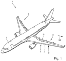
- FIG. 1 an aircraft 1 according to an embodiment of the present invention is illustrated.
- the aircraft 1 comprises a fuselage 2 and wings 3 that are formed according to an embodiment of the present invention.
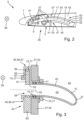
- Fig. 2 shows a wing 3 according to the invention in more detail.
- the wing 3 comprises a main wing 5, a slat 7, and a connection assembly 9 movably connecting the slat 7 to the main wing 5, such that the slat 7 is movable between a retracted position and at least one extended position.
- the connection assembly 9 comprises an elongate slat track 17 that extends along a track longitudinal axis 19 between a front end 21 and a rear end 23 and has an intermediate portion 25 between the front and rear ends 21, 23.
- the front end 21 of the slat track 17 is fixedly mounted to the slat 7.
- the rear end 23 and the intermediate portion 25 of the slat track 17 are movably mounted to the main wing 5 by a guide bearing 27, e.g. a roller bearing or a slide bearing, such that the slat track 17 is movable along the track longitudinal axis 19 within a predefined path between a stowed position 29, when the slat 7 is in the retracted position, as illustrated in Fig. 2 , and at least one deployed position (not shown), when the slat 7 is in the at least one extended position.
- a guide bearing 27 e.g. a roller bearing or a slide bearing
- the main wing 5 comprises a wing box 35 including a front spar 37 extending in a span direction 39 and from an upper skin to a lower skin of the main wing 5.
- the front spar 37 includes an aperture 41 for the slat track 17 to reach through into an interior 42 of the wing box 35 used as fuel tank, when the slat track 17 is in the stowed position 29.
- the main wing 5 further comprises a track housing assembly 43 including a track housing 45, also known as "track can", and a mounting device 47.
- the track housing 45 is mounted to the front spar 37 around the aperture 41 by the mounting device 47 and extending from the front spar 37 to the interior 42 of the wing box 35, so that the track housing 45 may receive at least a part of the slat track 17 when the slat track 17 is in the stowed position 29 and reaches through the aperture 41.
- the track housing 45 separates the interior 42 of the wing box 49 vis-à-vis the slat track 17 in a sealing manner, such that no fuel may leak out of the interior 42 of the wing box 35.
- the mounting device 47 comprises a quick release mount 49 for mounting the track housing 45 to the front spar 37.
- the quick release mount 49 in the present embodiment is formed as a bayonet mount 50.
- the track housing 45 comprises a housing wall 51 surrounding a housing interior 53 and extending in an elongate and curved manner from a housing front end 55 to a housing rear end 57. At the housing front end 55 an opening 59 is provided in the housing wall 51, while the housing rear end 57 is closed by the housing wall 51.
- the track housing 45 is mounted to the front spar 37 in such a way that the opening 59 is aligned with the aperture 41 in the front spar 37, so that the slat track 17 may reach through the opening 59 into the housing interior 53 when the slat track 17 is in the stowed position 29.
- the housing wall 51 separates and seals the interior 42 of the wing box 35 vis-à-vis the housing interior 53 with the slat track 17.
- the mounting device 47 comprises a first mounting part 61 fixedly mounted to or formed integrally with the housing wall 51 of the track housing 45 at the housing front end 55, and a second mounting part 63 mounted to the front spar 37 around the aperture 41.
- the first mounting part 61 and the second mounting part 63 are configured to be releasably engaged with one another.
- the first mounting part 61 and the second mounting part 63 are configured to be releasably engaged with one another by relative rotation of the first and second mounting parts 61, 63 about an engagement axis 65, wherein the engagement axis 65 defines the opening 59 and the aperture 41 and extends perpendicular to the front spar 37.
- the first mounting part 61 comprises four equally spaced locking flanges 67.
- the second mounting part 63 comprises four equally spaced locking undercuts 69.
- the second mounting part 63 is mounted to the front spar 37 in such a way that the at least one locking undercut 69, and in the mounted state also the at least one locking flange 67, is arranged at a front side of the front spar 37, so that the track housing 45 can be mounted from outside the wing box 35 by being inserted from the front through the aperture 41 into the interior 42 of the wing box 35 and then locked by engaging first and second mounting parts 61, 63.
- the second mounting part 63 is formed and mounted to the front spar 37 in such a way that a portion of the second mounting part 63 extends through the aperture 41 in the front spar 37 in the form of a sleeve, thereby simplifying insertion and sealing of the track housing 45 within the aperture 41.
- the mounting device 47 further comprises a sealing arrangement 75 including several sealing elements 77 in the form of sealing beads and O-rings arranged between the first mounting part 61 and the second mounting part 63 and between the track housing 45 and the front spar 37, thereby sealing the interior 42 of the wing box 35 with the fuel tank vis-à-vis the environment outside the wing box 35.
Landscapes
- Engineering & Computer Science (AREA)
- Aviation & Aerospace Engineering (AREA)
- Mechanical Engineering (AREA)
- Connection Of Plates (AREA)
- Fittings On The Vehicle Exterior For Carrying Loads, And Devices For Holding Or Mounting Articles (AREA)
- Turbine Rotor Nozzle Sealing (AREA)
Abstract
Description
- The present invention relates to a wing for an aircraft. Further aspects of the invention relate to a track housing assembly for such a wing, as well as to an aircraft comprising such a wing and/or such a track housing assembly.
- The wing comprises a main wing, a slat, and a connection assembly movably connecting the slat to the main wing, such that the slat is movable between a retracted position and at least one extended position.
- The connection assembly comprises an elongate slat track that extends along a curved or straight track longitudinal axis between a front end and a rear end and has an intermediate portion between the front and rear ends. The front end of the slat track is mounted to the slat, preferably in a fixed and/or direct manner, e.g. by two spherical bearings, both arranged with an offset in a wing profile plane across a wing span direction. The rear end and/or the intermediate portion of the slat track are mounted to the main wing by a guide bearing, such as a roller bearing or a slide bearing, such that the slat track is movable along the track longitudinal axis along a predefined path between a stowed position, preferably when the slat is in the retracted position, and at least one deployed position, preferably when the slat is in the at least one extended position.
- The main wing comprises a wing box including a front spar preferably extending in a span direction and from an upper skin to a lower skin of the main wing. The front spar includes an aperture for the slat track to reach through into an interior of the wing box, which is preferably used as fuel tank, when the slat track is in the stowed position.
- The main wing further comprises a track housing assembly including a track housing, also known as "track can", and a mounting device. The track housing is mounted to the front spar at the aperture, preferably around the aperture, by the mounting device and extending from the front spar to the interior of the wing box, so that the track housing may receive at least a part of the slat track when the slat track is in the stowed position and/or in a partly deployed position and reaches through the aperture. The track housing preferably separates the interior of the wing box vis-à-vis the slat track in a sealing manner, preferably such that no fuel may leak out of the interior of the wing box.
- Such wings are known in the art. In the known wings, the mounting device comprises a mounting flange at the track housing extending circumferentially around the opening of the track housing. The mounting flange is usually screwed or riveted to the inner surface of the front spar around the aperture from the interior of the wing box, i.e. from the tank, which is a difficult, laborious and time-consuming procedure both for installation as well as for maintenance.
- Therefore, the object of the present invention is to simplify installation and maintenance of the track housing at the front spar.
- This object is achieved in that the mounting device comprises a quick release mount for mounting the track housing to the front spar. By such a quick release mount, installation and maintenance of the track housing at the front spar can be essentially simplified and accelerated.
- According to a preferred embodiment, the quick release mount is formed as a bayonet mount. A bayonet mount relates to a very simple, reliable and quickly locking and unlocking quick release mount.
- According to a preferred embodiment, the track housing comprises a housing wall surrounding a housing interior and extending preferably in an elongate and curved or straight manner from a housing front end to a housing rear end. At the housing front end an opening is provided in the housing wall, while the housing rear end is preferably closed by the housing wall or by a separate part. The track housing is mounted to the front spar in such a way that the opening is aligned with the aperture in the front spar, so that the slat track may reach through the opening into the housing interior when the slat track is in the stowed position. Preferably, the housing wall separates and seals the interior of the wing box vis-à-vis the housing interior with the slat track. In such a way, a simple and reliable track housing is formed that can reliably seal the fuel tank in the interior of the wing box from the environment.
- According to a preferred embodiment, the mounting device comprises a first mounting part mounted to or formed integrally with the track housing, in particular with the housing wall, preferably at the housing front end, and a second mounting part mounted to or formed integrally with the front spar at the aperture, preferably in or around the aperture. The first mounting part and the second mounting part are configured to be engaged with one another, preferably releasably engaged with one another. In case the first mounting part and the second mounting part are configured to be releasably engaged with one another, the first mounting part and the second mounting part are preferably configured to be locked in the engaged state, preferably by a locking device including e.g. one or more latches or screws. The locking device is preferably also releasable. In such a way, a very efficient quick release mount is formed.
- In particular, it is preferred that the first mounting part and the second mounting part are configured to be engaged with one another, preferably releasably engaged with one another, by relative rotation of the first and second mounting parts about an engagement axis, preferably defining the opening and/or the aperture and perpendicular to the front spar. In such a way, a very efficient bayonet mount is formed.
- It is further preferred that one of the first mounting part and the second mounting part, preferably the first mounting part, comprises at least one locking flange, preferably in the form of a bayonet flange, preferably at least two equally spaced locking flanges, more preferred at least three equally spaced locking flanges, most preferred at least four equally spaced locking flanges. Preferably, the other one of the first mounting part and the second mounting part, preferably the second mounting part, comprises at least one locking undercut, preferably in the form of a bayonet undercut, preferably at least two equally spaced locking undercuts, more preferred at least three equally spaced locking undercuts, most preferred at least four equally spaced locking undercuts. By relative rotation of the first mounting part and the second mounting part about the engagement axis, preferably by rotation of the first mounting part relative to the second mounting part, the locking flange(s) can be moved into the locking undercut(s) to lock the first mounting part to the second mounting part and inhibit relative movement of the first and second locking parts in parallel to the engagement axis. In such a way, a very efficient bayonet mount is formed.
- In particular, it is preferred that the second mounting part is mounted to the front spar in such a way that the at least one locking undercut, and in the mounted state also the at least one locking flange, is arranged at a front side of the front spar, so that the track housing can be mounted from outside the wing box, i.e. inserted from the front through the aperture into the interior of the wing box and then locked by engaging first and second mounting parts. In such a way, installation and maintenance of the track housing can be essentially simplified and accelerated, as it is not necessary to work from the interior of the wing box with its limited space.
- Alternatively, it is preferred that the second mounting part is mounted to the front spar in such a way that the at least one locking undercut, and in the mounted state also the at least one locking flange, is arranged at a rear side of the front spar, so that the track housing can be mounted from the interior of the wing box, i.e. inserted in the interior of the wing box and then fitted to the aperture and locked by engaging first and second mounting parts at the rear side of the front spar. This relates to an alternative way of mounting the track housing where all parts of the track housing and the mounting device can be in the interior of the wing box and the track housing and mounting device might be entirely supported at the rear side of the front spar.
- According to a preferred embodiment, the second mounting part is formed and mounted to the front spar in such a way that a portion of the second mounting part extends through the aperture in the front spar in the form of a sleeve, thereby simplifying insertion and sealing of the track housing within the aperture. In such a way, a very efficient bayonet mount is formed.
- According to another preferred embodiment, the mounting device comprises a sealing arrangement including at least one sealing element, preferably in the form of at least one sealing bead and/or at least one O-ring, arranged between the first mounting part and the second mounting part and/or between the track housing and the front spar, thereby sealing the interior of the wing box, in particular the fuel tank, vis-à-vis the environment outside the wing box. In such a way, the environment of the slat track can be reliably sealed from the fuel tank and vice-versa.
- A further aspect of the invention relates to a track housing assembly for the wing according to any of the embodiments described above. The track housing assembly comprises a track housing and a mounting device. The track housing is configured to be mounted to a front spar of a main wing by the mounting device, so that the track housing may extend from the front spar to an interior of a wing box and may receive at least a part of a slat track when the slat track is in a stowed position. The mounting device comprises a quick release mount for mounting the track housing to the front spar. The features and effects described above with respect to the wing apply vis-à-vis also to the track housing assembly.
- A further aspect of the invention relates to an aircraft comprising the wing according to any of the embodiments described above and/or comprising the track housing assembly according to any of the embodiments described above. The features and effects described above with respect to the wing and the track housing assembly apply vis-à-vis also to the aircraft.
- Hereinafter, a preferred embodiment of the present invention is explained in more detail by means of a drawing. The drawing shows in
- Fig. 1
- a perspective view of an aircraft according to the present invention,
- Fig. 2
- a cross sectional view across the span direction of a wing of the aircraft shown in
Fig. 1 , - Fig. 3
- a schematic cross sectional view along the engagement axis of a track housing assembly as used in the wing shown in
Fig. 2 , and - Fig. 4
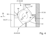
- a schematic front view (left side) and cross sectional view across the engagement axis (right side) of the track housing assembly shown in
Fig. 3 . - In
Fig. 1 anaircraft 1 according to an embodiment of the present invention is illustrated. Theaircraft 1 comprises afuselage 2 andwings 3 that are formed according to an embodiment of the present invention. -
Fig. 2 shows awing 3 according to the invention in more detail. Thewing 3 comprises amain wing 5, aslat 7, and aconnection assembly 9 movably connecting theslat 7 to themain wing 5, such that theslat 7 is movable between a retracted position and at least one extended position. - The
connection assembly 9 comprises anelongate slat track 17 that extends along a tracklongitudinal axis 19 between afront end 21 and arear end 23 and has anintermediate portion 25 between the front andrear ends front end 21 of theslat track 17 is fixedly mounted to theslat 7. Therear end 23 and theintermediate portion 25 of theslat track 17 are movably mounted to themain wing 5 by a guide bearing 27, e.g. a roller bearing or a slide bearing, such that theslat track 17 is movable along the tracklongitudinal axis 19 within a predefined path between a stowedposition 29, when theslat 7 is in the retracted position, as illustrated inFig. 2 , and at least one deployed position (not shown), when theslat 7 is in the at least one extended position. - The
main wing 5 comprises awing box 35 including afront spar 37 extending in aspan direction 39 and from an upper skin to a lower skin of themain wing 5. Thefront spar 37 includes anaperture 41 for theslat track 17 to reach through into an interior 42 of thewing box 35 used as fuel tank, when theslat track 17 is in the stowedposition 29. - The
main wing 5 further comprises atrack housing assembly 43 including atrack housing 45, also known as "track can", and a mountingdevice 47. Thetrack housing 45 is mounted to thefront spar 37 around theaperture 41 by the mountingdevice 47 and extending from thefront spar 37 to the interior 42 of thewing box 35, so that thetrack housing 45 may receive at least a part of theslat track 17 when theslat track 17 is in the stowedposition 29 and reaches through theaperture 41. Thetrack housing 45 separates the interior 42 of the wing box 49 vis-à-vis theslat track 17 in a sealing manner, such that no fuel may leak out of the interior 42 of thewing box 35. - As shown in
Figs. 3 and4 , the mountingdevice 47 comprises a quick release mount 49 for mounting thetrack housing 45 to thefront spar 37. The quick release mount 49 in the present embodiment is formed as a bayonet mount 50. - The
track housing 45 comprises ahousing wall 51 surrounding ahousing interior 53 and extending in an elongate and curved manner from a housingfront end 55 to a housingrear end 57. At the housingfront end 55 anopening 59 is provided in thehousing wall 51, while the housingrear end 57 is closed by thehousing wall 51. Thetrack housing 45 is mounted to thefront spar 37 in such a way that theopening 59 is aligned with theaperture 41 in thefront spar 37, so that theslat track 17 may reach through theopening 59 into thehousing interior 53 when theslat track 17 is in the stowedposition 29. Thehousing wall 51 separates and seals the interior 42 of thewing box 35 vis-à-vis thehousing interior 53 with theslat track 17. - As shown in
Figs. 3 and4 , the mountingdevice 47 comprises a first mountingpart 61 fixedly mounted to or formed integrally with thehousing wall 51 of thetrack housing 45 at the housingfront end 55, and a second mountingpart 63 mounted to thefront spar 37 around theaperture 41. The first mountingpart 61 and the second mountingpart 63 are configured to be releasably engaged with one another. Specifically, the first mountingpart 61 and the second mountingpart 63 are configured to be releasably engaged with one another by relative rotation of the first and second mountingparts engagement axis 65, wherein theengagement axis 65 defines theopening 59 and theaperture 41 and extends perpendicular to thefront spar 37. - As also shown in
Figs. 3 and4 , the first mountingpart 61 comprises four equally spaced lockingflanges 67. The second mountingpart 63 comprises four equally spaced locking undercuts 69. By rotation of thetrack housing 45 with the first mountingpart 61 relative to the second mountingpart 63, the lockingflanges 67 can be moved into the locking undercuts 69 to lock the first mountingpart 61 to the second mountingpart 63 and inhibit relative movement of the first and second mountingparts engagement axis 65. The second mountingpart 63 is mounted to thefront spar 37 in such a way that the at least one locking undercut 69, and in the mounted state also the at least one lockingflange 67, is arranged at a front side of thefront spar 37, so that thetrack housing 45 can be mounted from outside thewing box 35 by being inserted from the front through theaperture 41 into the interior 42 of thewing box 35 and then locked by engaging first and second mountingparts - The second mounting
part 63 is formed and mounted to thefront spar 37 in such a way that a portion of the second mountingpart 63 extends through theaperture 41 in thefront spar 37 in the form of a sleeve, thereby simplifying insertion and sealing of thetrack housing 45 within theaperture 41. The mountingdevice 47 further comprises a sealing arrangement 75 including several sealing elements 77 in the form of sealing beads and O-rings arranged between the first mountingpart 61 and the second mountingpart 63 and between thetrack housing 45 and thefront spar 37, thereby sealing the interior 42 of thewing box 35 with the fuel tank vis-à-vis the environment outside thewing box 35. - By a quick release mount 49 according to the present invention as described above, installation and maintenance of the
track housing 45 at thefront spar 37 can be essentially simplified and accelerated.
Claims (12)
- A wing (3) for an aircraft (1), comprisinga main wing (5),a slat (7), anda connection assembly (9) movably connecting the slat (7) to the main wing (5), such that the slat (7) is movable between a retracted position and at least one extended position,wherein the connection assembly (9) comprises an elongate slat track (17) that extends along a track longitudinal axis (19) between a front end (21) and a rear end (23) and has an intermediate portion (25) between the front and rear ends (21, 23),wherein the front end (21) of the slat track (17) is mounted to the slat (7),wherein the rear end (23) and/or the intermediate portion (25) of the slat track (17) are mounted to the main wing (5) by a guide bearing (27), such that the slat track (17) is movable along the track longitudinal axis (19) between a stowed position (29) and a deployed position,wherein the main wing (5) comprises a wing box (35) including a front spar (37),wherein the front spar (37) includes an aperture (41) for the slat track (17) to reach through when the slat track (17) is in the stowed position (29),wherein the main wing (5) comprises a track housing assembly (43) including a track housing (45) and a mounting device (47), wherein the track housing (45) is mounted to the front spar (37) at the aperture (41) by the mounting device (47) and extending from the front spar (37) to the interior (42) of the wing box (35), so that the track housing (45) may receive at least a part of the slat track (17) when the slat track (17) is in the stowed position (29),characterized in thatthe mounting device (47) comprises a quick release mount (49) for mounting the track housing (45) to the front spar (37).
- The wing (3) according to claim 1, wherein the quick release mount (49) is formed as a bayonet mount (50).
- The wing (3) according to claim 1 or 2, wherein the track housing (45) comprises a housing wall (51) surrounding a housing interior (53) and extending from a housing front end (55) to a housing rear end (57),wherein at the housing front end (55) an opening (59) is provided in the housing wall (51),wherein the track housing (45) is mounted to the front spar (37) in such a way that the opening (59) is aligned with the aperture (41) in the front spar (37), so that the slat track (17) may reach through the opening (59) into the housing interior (53) when the slat track (17) is in the stowed position (29).
- The wing (3) according to any of claims 1 to 3, wherein the mounting device (47) comprises a first mounting part (61) mounted to or formed integrally with the track housing (45) and a second mounting part (63) mounted to or formed integrally with the front spar (37) at the aperture (41),
wherein the first mounting part (61) and the second mounting part (63) are configured to be engaged with one another. - The wing (3) according to claim 4, wherein the first mounting part (61) and the second mounting part (63) are configured to be engaged with one another by relative rotation of the first and second mounting parts (61, 63) about an engagement axis (65).
- The wing (3) according to claim 4 or 5, wherein one of the first mounting part (61) and the second mounting part (63) comprises at least one locking flange (67), preferably at least two spaced locking flanges (67), more preferred at least three spaced locking flanges (67), most preferred at least four spaced locking flanges (67),wherein the other one of the first mounting part (61) and the second mounting part (63) comprises at least one locking undercut (69), preferably at least two spaced locking undercuts (69), more preferred at least three spaced locking undercuts (69), most preferred at least four spaced locking undercuts (69),wherein by relative rotation of the first mounting part (61) and the second mounting part (63) about the engagement axis (65) the locking flange (67) can be moved into the locking undercut (69) to lock the first mounting part (61) to the second mounting part (63).
- The wing (3) according to claim 6, wherein the second mounting part (63) is mounted to the front spar (37) in such a way that the at least one locking undercut (69) is arranged at a front side of the front spar (37).
- The wing (3) according to claim 6, wherein the second mounting part (63) is mounted to the front spar (37) in such a way that the at least one locking undercut (69) is arranged at a rear side of the front spar (37).
- The wing (3) according to any of claims 4 to 8, wherein the second mounting part (63) is formed and mounted to the front spar (37) in such a way that a portion of the second mounting part (63) extends through the aperture (41) in the front spar (37) in the form of a sleeve.
- The wing (3) according to any of claims 4 to 9, wherein the mounting device (47) comprises a sealing arrangement (75) including at least one sealing element (77) arranged between the first mounting part (61) and the second mounting part (63) and/or between the track housing (45) and the front spar (37), thereby sealing the interior (42) of the wing box (35) vis-à-vis the environment outside the wing box (35).
- A track housing assembly (43) for the wing (3) according to any of claims 1 to 10, the track housing assembly (43) comprisinga track housing (45), anda mounting device (47),wherein the track housing (45) is configured to be mounted to a front spar (37) of a main wing (5) by the mounting device (47), so that the track housing (45) may extend from the front spar (37) to an interior (42) of a wing box (35) and may receive at least a part of a slat track (17) when the slat track (17) is in a stowed position (29),characterized in thatthe mounting device (47) comprises a quick release mount (49) for mounting the track housing (45) to the front spar (37).
- An aircraft (1) comprising the wing (3) according to any of claims 1 to 10 and/or comprising the track housing assembly (43) according to claim 11.
Priority Applications (3)
| Application Number | Priority Date | Filing Date | Title |
|---|---|---|---|
| EP23151780.6A EP4400412A1 (en) | 2023-01-16 | 2023-01-16 | Wing for an aircraft |
| US18/406,989 US12351309B2 (en) | 2023-01-16 | 2024-01-08 | Wing for an aircraft |
| CN202410048771.1A CN118343286A (en) | 2023-01-16 | 2024-01-12 | Wing for aircraft, track shell assembly and aircraft |
Applications Claiming Priority (1)
| Application Number | Priority Date | Filing Date | Title |
|---|---|---|---|
| EP23151780.6A EP4400412A1 (en) | 2023-01-16 | 2023-01-16 | Wing for an aircraft |
Publications (1)
| Publication Number | Publication Date |
|---|---|
| EP4400412A1 true EP4400412A1 (en) | 2024-07-17 |
Family
ID=84981298
Family Applications (1)
| Application Number | Title | Priority Date | Filing Date |
|---|---|---|---|
| EP23151780.6A Pending EP4400412A1 (en) | 2023-01-16 | 2023-01-16 | Wing for an aircraft |
Country Status (3)
| Country | Link |
|---|---|
| US (1) | US12351309B2 (en) |
| EP (1) | EP4400412A1 (en) |
| CN (1) | CN118343286A (en) |
Citations (3)
| Publication number | Priority date | Publication date | Assignee | Title |
|---|---|---|---|---|
| US20100258674A1 (en) * | 2009-04-08 | 2010-10-14 | Airbus Operations Limited | Track container |
| WO2010122324A2 (en) * | 2009-04-23 | 2010-10-28 | Airbus Operations Limited | Aircraft assembly and spar |
| US20180135735A1 (en) * | 2016-11-14 | 2018-05-17 | Airbus Operations Limited | Roller components |
Family Cites Families (3)
| Publication number | Priority date | Publication date | Assignee | Title |
|---|---|---|---|---|
| GB9104370D0 (en) * | 1991-03-01 | 1991-04-17 | British Aerospace | Manufacture of track cans |
| GB0816022D0 (en) * | 2008-09-03 | 2008-10-08 | Airbus Uk Ltd | Slat support assembly |
| GB2527490A (en) * | 2014-04-17 | 2015-12-30 | Ip Dept Airbus Operations Ltd | A bearing block for a slat support assembly |
-
2023
- 2023-01-16 EP EP23151780.6A patent/EP4400412A1/en active Pending
-
2024
- 2024-01-08 US US18/406,989 patent/US12351309B2/en active Active
- 2024-01-12 CN CN202410048771.1A patent/CN118343286A/en active Pending
Patent Citations (3)
| Publication number | Priority date | Publication date | Assignee | Title |
|---|---|---|---|---|
| US20100258674A1 (en) * | 2009-04-08 | 2010-10-14 | Airbus Operations Limited | Track container |
| WO2010122324A2 (en) * | 2009-04-23 | 2010-10-28 | Airbus Operations Limited | Aircraft assembly and spar |
| US20180135735A1 (en) * | 2016-11-14 | 2018-05-17 | Airbus Operations Limited | Roller components |
Also Published As
| Publication number | Publication date |
|---|---|
| US12351309B2 (en) | 2025-07-08 |
| US20240239473A1 (en) | 2024-07-18 |
| CN118343286A (en) | 2024-07-16 |
Similar Documents
| Publication | Publication Date | Title |
|---|---|---|
| US10173783B2 (en) | Rotorcraft with cowling able to rotate and translate relative to the fuselage | |
| US10066430B2 (en) | Sliding closing element, in particular a sliding door or a sliding window, for a sliding closing element arrangement of a vehicle, in particular of an aircraft | |
| US4541595A (en) | Removable interior window unit for aircraft | |
| RU2657124C2 (en) | Vehicle window glass run system | |
| US10946948B2 (en) | Slide and rotating cockpit door and method | |
| EP3059157B1 (en) | Rotorcraft with cowling able to rotate and translate relative to the fuselage | |
| GB2527185A (en) | Vent stringer fitting | |
| EP3656657B1 (en) | Aircraft fuel tank aperture sealing | |
| US11142327B2 (en) | Aircraft turbomachine assembly comprising an articulated cowl | |
| US7448656B1 (en) | Dual action structural latch | |
| CN113950446A (en) | Carrier area with a luggage compartment and a roof panel above the luggage compartment and method for mounting and dismounting the roof panel above the luggage compartment | |
| US11319084B2 (en) | Propulsive assembly of an aircraft comprising a junction fairing between a nacelle and a pylon of the aircraft equipped with a removable cowl and aircraft equipped with said propulsive assembly | |
| US12117115B2 (en) | Electrical pass-through assembly for traversing a structure | |
| US12351309B2 (en) | Wing for an aircraft | |
| US20050133667A1 (en) | Aircraft door | |
| US12188511B2 (en) | Nut cap assembly | |
| EP3323711B1 (en) | Lockable track system for a translating nacelle structure | |
| EP3778379A1 (en) | Nut plate assembly | |
| CN118220495A (en) | Aircraft with engine pylons having movable fairings | |
| CN216300939U (en) | Fixing device and vehicle decoration assembly | |
| EP3957894B1 (en) | Fuel pipe assembly | |
| US20240239507A1 (en) | Aircraft having a locking device and a system for visual indication of the state of said locking device | |
| KR101979332B1 (en) | Rotorcraft with cowling able to rotate and translate relative to the fuselage | |
| US20240026913A1 (en) | Coupling kit-of-parts for a mounting arrangement for mounting an interior substructure to a primary structure of an aircraft | |
| US20230322386A1 (en) | Multi-receptacle payload assembly for aircraft |
Legal Events
| Date | Code | Title | Description |
|---|---|---|---|
| PUAI | Public reference made under article 153(3) epc to a published international application that has entered the european phase |
Free format text: ORIGINAL CODE: 0009012 |
|
| STAA | Information on the status of an ep patent application or granted ep patent |
Free format text: STATUS: THE APPLICATION HAS BEEN PUBLISHED |
|
| AK | Designated contracting states |
Kind code of ref document: A1 Designated state(s): AL AT BE BG CH CY CZ DE DK EE ES FI FR GB GR HR HU IE IS IT LI LT LU LV MC ME MK MT NL NO PL PT RO RS SE SI SK SM TR |
|
| STAA | Information on the status of an ep patent application or granted ep patent |
Free format text: STATUS: REQUEST FOR EXAMINATION WAS MADE |
|
| 17P | Request for examination filed |
Effective date: 20250115 |
|
| GRAP | Despatch of communication of intention to grant a patent |
Free format text: ORIGINAL CODE: EPIDOSNIGR1 |
|
| STAA | Information on the status of an ep patent application or granted ep patent |
Free format text: STATUS: GRANT OF PATENT IS INTENDED |
|
| INTG | Intention to grant announced |
Effective date: 20251118 |
|
| GRAJ | Information related to disapproval of communication of intention to grant by the applicant or resumption of examination proceedings by the epo deleted |
Free format text: ORIGINAL CODE: EPIDOSDIGR1 |
|
| STAA | Information on the status of an ep patent application or granted ep patent |
Free format text: STATUS: REQUEST FOR EXAMINATION WAS MADE |
|
| INTC | Intention to grant announced (deleted) | ||
| GRAP | Despatch of communication of intention to grant a patent |
Free format text: ORIGINAL CODE: EPIDOSNIGR1 |
|
| STAA | Information on the status of an ep patent application or granted ep patent |
Free format text: STATUS: GRANT OF PATENT IS INTENDED |