EP4400410A1 - Interchangeable air distribution coupling interface for an internal cabin of a vehicle - Google Patents
Interchangeable air distribution coupling interface for an internal cabin of a vehicle Download PDFInfo
- Publication number
- EP4400410A1 EP4400410A1 EP23209425.0A EP23209425A EP4400410A1 EP 4400410 A1 EP4400410 A1 EP 4400410A1 EP 23209425 A EP23209425 A EP 23209425A EP 4400410 A1 EP4400410 A1 EP 4400410A1
- Authority
- EP
- European Patent Office
- Prior art keywords
- floor
- air distribution
- outlet port
- coupling interface
- air
- Prior art date
- Legal status (The legal status is an assumption and is not a legal conclusion. Google has not performed a legal analysis and makes no representation as to the accuracy of the status listed.)
- Pending
Links
Images


Classifications
-
- B—PERFORMING OPERATIONS; TRANSPORTING
- B64—AIRCRAFT; AVIATION; COSMONAUTICS
- B64C—AEROPLANES; HELICOPTERS
- B64C1/00—Fuselages; Constructional features common to fuselages, wings, stabilising surfaces or the like
- B64C1/18—Floors
-
- B—PERFORMING OPERATIONS; TRANSPORTING
- B64—AIRCRAFT; AVIATION; COSMONAUTICS
- B64D—EQUIPMENT FOR FITTING IN OR TO AIRCRAFT; FLIGHT SUITS; PARACHUTES; ARRANGEMENT OR MOUNTING OF POWER PLANTS OR PROPULSION TRANSMISSIONS IN AIRCRAFT
- B64D11/00—Passenger or crew accommodation; Flight-deck installations not otherwise provided for
- B64D11/06—Arrangements of seats, or adaptations or details specially adapted for aircraft seats
- B64D11/0626—Arrangements of seats, or adaptations or details specially adapted for aircraft seats with individual temperature or ventilation control
-
- B—PERFORMING OPERATIONS; TRANSPORTING
- B64—AIRCRAFT; AVIATION; COSMONAUTICS
- B64D—EQUIPMENT FOR FITTING IN OR TO AIRCRAFT; FLIGHT SUITS; PARACHUTES; ARRANGEMENT OR MOUNTING OF POWER PLANTS OR PROPULSION TRANSMISSIONS IN AIRCRAFT
- B64D13/00—Arrangements or adaptations of air-treatment apparatus for aircraft crew or passengers, or freight space
- B64D13/06—Arrangements or adaptations of air-treatment apparatus for aircraft crew or passengers, or freight space the air being conditioned
-
- B—PERFORMING OPERATIONS; TRANSPORTING
- B64—AIRCRAFT; AVIATION; COSMONAUTICS
- B64D—EQUIPMENT FOR FITTING IN OR TO AIRCRAFT; FLIGHT SUITS; PARACHUTES; ARRANGEMENT OR MOUNTING OF POWER PLANTS OR PROPULSION TRANSMISSIONS IN AIRCRAFT
- B64D13/00—Arrangements or adaptations of air-treatment apparatus for aircraft crew or passengers, or freight space
-
- B—PERFORMING OPERATIONS; TRANSPORTING
- B64—AIRCRAFT; AVIATION; COSMONAUTICS
- B64D—EQUIPMENT FOR FITTING IN OR TO AIRCRAFT; FLIGHT SUITS; PARACHUTES; ARRANGEMENT OR MOUNTING OF POWER PLANTS OR PROPULSION TRANSMISSIONS IN AIRCRAFT
- B64D13/00—Arrangements or adaptations of air-treatment apparatus for aircraft crew or passengers, or freight space
- B64D2013/003—Cabin ventilation nozzles
-
- B—PERFORMING OPERATIONS; TRANSPORTING
- B64—AIRCRAFT; AVIATION; COSMONAUTICS
- B64D—EQUIPMENT FOR FITTING IN OR TO AIRCRAFT; FLIGHT SUITS; PARACHUTES; ARRANGEMENT OR MOUNTING OF POWER PLANTS OR PROPULSION TRANSMISSIONS IN AIRCRAFT
- B64D13/00—Arrangements or adaptations of air-treatment apparatus for aircraft crew or passengers, or freight space
- B64D13/06—Arrangements or adaptations of air-treatment apparatus for aircraft crew or passengers, or freight space the air being conditioned
- B64D2013/0603—Environmental Control Systems
- B64D2013/0625—Environmental Control Systems comprising means for distribution effusion of conditioned air in the cabin
Definitions
- Examples of the present disclosure generally relate to an interchangeable air distribution coupling interface for an internal cabin of a vehicle, such as a commercial aircraft.
- Aircraft are used to transport passengers and cargo between various locations.
- Aircraft typically include an air distribution system that provides airflow within an internal cabin.
- Connection joints typically couple to conduits that connect to the air distribution system.
- the connection joints are typically permanently bonded to a surface of a floor of the internal cabin. Because the connection joints are permanently bonded to the floor, certain features of the internal cabin are not reconfigurable without extensive rework to remove the connection joint, and typically one or more floor panels on which the connection joint is secured. Additionally, known connection joints generally do not allow for future seat location provisions (for example, additional seating) without extensive modification to the floor. Overall, known connections joints hinder quick and easy reconfiguration of various features of an internal cabin of an aircraft.
- an air distribution coupling interface configured to removably secure to a floor of an internal cabin of a vehicle.
- the air distribution coupling interface includes a main tube extending between an air inlet port and an air outlet port.
- the air inlet port is configured to couple to one or more conduits that are in fluid communication with an air distribution system.
- a securing flange is configured to removably secure the air distribution coupling interface to the floor of the internal cabin.
- the air outlet port is configured to deliver airflow provided by the air distribution system.
- the securing flange is not permanently bonded to the floor.
- the securing flange is configured to removably secure to the floor through one or more fasteners.
- the air inlet port is configured to be underneath the floor when the air distribution coupling interface is secured to the floor.
- the air outlet port is configured to deliver the airflow above the floor.
- the main tube is arcuate.
- connection tube securable to the air outlet port.
- a cap is securable to the air outlet port.
- the connection tube and the cap are interchangeably securable to the air outlet port.
- the securing flange is configured to removably secure to a lower surface of the floor.
- the air outlet port can be configured to deliver the airflow to a seat assembly within the internal cabin.
- Certain examples of the present disclosure provide a method for removably securing an air distribution coupling interface to a floor of an internal cabin of a vehicle, wherein the air distribution coupling interface comprises a securing flange, and a main tube extending between an air inlet port and an air outlet port, the method includes coupling the air outlet port to one or more conduits that are in fluid communication with an air distribution system; removably securing, by the securing flange, the air distribution coupling interface to the floor; and delivering airflow, by the air outlet port, provided by the air distribution system.
- Certain examples of the present disclosure provide a vehicle including an internal cabin, a floor within the internal cabin, and an air distribution coupling interface removably secured to the floor of the internal cabin, as described herein.
- certain examples of the present disclosure provide an air distribution coupling interface that is configured to be in fluid communication with an air distribution system, such as via one or more conduits routed underneath a floor of an internal cabin of a vehicle.
- the air distribution coupling interface is removably secured to the floor, such as via one or more fasteners, snaps, an interference fit, and/or the like, instead of being permanently bonded to the floor.
- the air distribution coupling interface is interchangeable.
- the air distribution coupling interface allows airflow to be provided to or proximate to a seat in a vehicle.
- Examples of the present disclosure provide an interchangeable through-floor air distribution coupling interface, which allows for both an installed seat at delivery to be connected to cabin air distribution and a seat to be hooked up to cabin air distribution in a post-delivery reconfiguration with minimum rework effort.
- the air distribution coupling interface is secured to a floor of an internal cabin through fasteners and/or threaded inserts.
- the air distribution coupling interface includes a flange that may not protrude through the floorboard when installed.
- the air distribution coupling interface allows for easy seat installation in relation to both pre- and post-delivery of a vehicle.
- the air distribution coupling interface may not be visible under a carpet if an operator of a vehicle chooses not to install a seat at a particular location.
- the operator can simply remove a cap of the air distribution coupling interface, and install an extension, thereby providing an interface to an air distribution system with minimal rework.
- the air distribution coupling interface allows seating configurations within an internal cabin of a vehicle, such as a commercial aircraft, to be efficiently and effectively updated in a cost-effective manner.
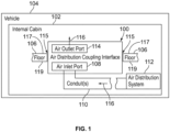
- Figure 1 illustrates a simplified block diagram of an air distribution coupling interface 100 within an internal cabin 102 of a vehicle 104, according to an example of the present disclosure.
- the vehicle 104 is an aircraft, such as a commercial jet.
- the vehicle 104 can be a land-based vehicle, such as an automobile, a bus, a train car, or the like.
- the vehicle 104 can be a watercraft.
- the vehicle 104 can be a spacecraft.
- the air distribution coupling interface 100 is removably secured to a floor 106 of the internal cabin 102.
- the air distribution coupling interface 100 is removably secured to the floor 106 through one or more fasteners.
- the air distribution coupling interface 100 is snapably secured to the floor 106, such as via one or more detents, deflectable beams, or the like.
- the air distribution coupling interface 100 can include threads that removably couple to reciprocal threads surrounding an opening within the floor 106.
- the air distribution coupling interface 100 includes an air inlet port 108, which can be underneath the floor 106.
- the air inlet port 108 fluidly couples to one or more conduits 110, such as one or more duct(s), tube(s), hoses, plenum(s), and/or the like, which fluidly couple to an air distribution system 112 of the vehicle 104.
- the air distribution system 112 can be or otherwise include a heating, ventilation, and air conditioning (HVAC) system, one or more air blowers, and/or the like.
- HVAC heating, ventilation, and air conditioning
- the air distribution system 112 is configured to provide conditioned, heated, circulated, and/or recirculated air to the internal cabin 102.
- the air distribution system 112 can be below the floor 106, above the floor 106, and/or supported on the floor 106.
- the conduit(s) 110 extend below the floor 106 and extend along a sidewall of the internal cabin 102.
- the air distribution coupling interface 100 also includes an air outlet port 114, which can extend above the floor 106.
- the air outlet port 114 can be flush with an upper surface of the floor 106.
- the air outlet port 114 can be recessed within the floor 106. Airflow 116 from the air distribution system is provided above the floor 106 by the air outlet port 114.
- the air distribution coupling interface 100 can be selectively secured and removed from one or more reciprocal openings 115 within the floor 106.
- the reciprocal openings 115 can be located throughout the internal cabin 102, thereby allowing for airflow to be delivered to various locations, as desired.
- the air distribution system 112 generates airflow 116, which is received by the air inlet port 108, and output through the air outlet port 114 at a desired location, such as underneath and/or to a seat assembly, within a monument (such as a galley, a closet, a lavatory, or the like), on or to sides of an aisle, and/or the like.
- a cap can be secured over the air outlet port 114 to prevent the airflow 116 from passing out of the air outlet port 114. If the airflow 116 is desired at the location at a later time, the cap can be removed from the air outlet port 114.
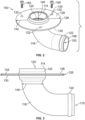
- Figure 2 illustrates an isometric top view of the air distribution coupling interface 100, according to an example of the present disclosure.
- Figure 3 illustrates a side view of the air distribution coupling interface 100 of Figure 2 .
- the air distribution coupling interface 100 includes a main tube 118 defining an internal passage 120 extending between the air inlet port 108 and the air outlet port 114.
- the main tube 118 can be arcuate.
- the main tube 118 has a smooth, curved shape without a right angle connection, thereby allowing for free and consistent fluid flow from the air inlet port 108 to the air outlet port 114.
- the air inlet port 108 includes an outer fitting 122 configured to secure retain an end of a conduit 110, such as a hose, tube, duct, and/or the like.
- the air outlet port 114 includes an outer circumferential surface 124 that is configured to receive and retain a cap and a connection tube. In at least one example, the outer circumferential surface 124 can be threaded.
- the air inlet port 108, the internal passage 120, and the air outlet port 114 can have circular cross-sections, in order to allow for free, efficient airflow therethrough.
- the air inlet port 108, the internal passage 120, and the air outlet port 114 can be sized and shaped differently than shown.
- the air distribution coupling interface 100 also includes a securing flange 126 radially and circumferentially extending around a portion of the main tube 118.
- the securing flange 126 is proximate to the air outlet port 114, such as less than 1 inch therefrom.
- the securing flange 126 is configured to removably secure the air distribution coupling interface 100 to the floor 106.
- the securing flange 126 includes a first surface 128, such as an upper surface, facing toward the air outlet port 114, and an opposite second surface 130, such as a lower surface, facing away from the air outlet port 114.
- One or more fastener through-holes 132 are formed through the securing flange 126 between and through the first surface 128 and the second surface 130.
- the fastener through-holes 132 are configured to receive fasteners 160, such as screws, bolts, or the like that are used to secure the securing flange 126 (and therefore the air distribution coupling interface 100) to the floor 106.
- the reciprocal opening 115 is formed through the floor 106 between and through an upper surface 117 and a lower surface 119.
- the reciprocal opening 115 can be a circular opening having a diameter.
- the diameter of the main tube 118 is smaller than the diameter of the reciprocal opening 115, thereby allowing the tube 118 to fit within the reciprocal opening 115.
- the diameter of the securing flange 126 is greater than the diameter of the reciprocal opening 115, thereby preventing the securing flange 126 from passing into the reciprocal opening 115.
- the second surface 130 of the securing flange 126 can rest on top of the upper surface 117 of the floor 106 surrounding the reciprocal opening 115, while the portion of the main tube 118 below the securing flange 126 passes through the reciprocal opening 115, thereby disposing the air inlet port 108 underneath the floor 106.
- the first surface 128 of the securing flange 126 can abut against, and be secured to, the lower surface 119 of the floor 106, and the air outlet port 114 can extend upwardly into the reciprocal opening 115.
- the diameter 140 of the main tube 118 can be 1.5 inches, and the diameter 142 of the securing flange is 4.5 inches.
- the diameter of the reciprocal opening 115 can be greater than 1.5 inches, but less than 4.5 inches.
- the diameter 140 can be greater or less than 1.5 inches
- the diameter 142 can be greater or less than 4.5 inches
- the diameter of the reciprocal opening 115 is greater than the diameter 140, but less than the diameter 142.
- the securing flange 126 is removably securable to the floor 106, such as through one or more fasteners 160, such as one or more screw(s), bolt(s), or the like. Accordingly, the securing flange 126 is not permanently bonded to the floor 106.
- the main tube 118 and/or the securing flange 126 can be removably secured to the floor 106 through a snapable interface, an interference fit, a threaded engagement (such as a threadable interface between an outer surface of the main tube 118 or the securing flange 126 and an internal edge of the floor 106 surrounding the reciprocal opening 115), and/or the like.
- the air distribution coupling interface 100 is configured to removably secure to the floor 106 of the internal cabin 102 of the vehicle 104.
- the air distribution coupling interface 100 includes the main tube 118 extending between the air inlet port 108 and the air outlet port 114.
- the air inlet port 108 is configured to couple to one or more conduits 110 that are in fluid communication with the air distribution system 112.
- the securing flange 126 is configured to removably secure the air distribution coupling interface 100 to the floor 106 of the internal cabin 102.
- the air outlet port 114 is configured to deliver airflow provided by the air distribution system 112.
- FIG 4 illustrates an isometric top view of a connection tube 170, according to an example of the present disclosure.
- Figure 5 illustrates a side view of the connection tube 170 of Figure 4 .
- the connection tube 170 includes a main body 172 defining a central passage 174 between an inlet end 176 and an outlet end 178.
- the connection tube 170 is configured to secure to the air outlet port 114.
- the inlet end 176 can fit around the air outlet port 114.
- the inlet end 176 can fit within the air outlet port 114.
- the inlet end 176 can threadably secure to the air outlet port 114.
- the inlet end 176 can snapably secure to the air outlet port 114.
- the inlet end 176 can secure to the air outlet port 114 through an interference fit.
- the inlet end 176 can be bonded to the air outlet port 114.
- connection tube 170 extends upwardly from the air outlet port 114, and provides a fitting for a conduit, such as a tube, hose, or the like, which can be used to channel airflow from the air distribution coupling interface 100 to a component, such as a portion of a seat assembly, a monument, or the like.
- a conduit such as a tube, hose, or the like
- the connection tube 170 can be straight and linear.
- the connection tube 170 can be curved, include one or more bends, or the like.
- FIG. 6 illustrates an isometric bottom view of a cap 180, according to an example of the present disclosure.
- the cap 180 includes an outer circumferential wall 182 connected to a cover 184.
- An internal chamber 186 is defined between the outer circumferential wall 182 and the cover 184.
- the cover 184 can include an opening 188 that allows for a reduced amount of airflow to pass therethrough.
- the cover 184 may not include the opening 188.
- the cap 180 is configured to be removably secured to the air outlet port 114.
- the cap 180 prevents airflow (or allows a reduced amount of airflow) from passing out of the air outlet port 114.
- the cap 180 can fit around the air outlet port 114, or be configured to fit within the air outlet port 114 to provide a plug.
- the cap 180 can threadably secure to the air outlet port 114.
- the cap 180 can snapably secure to the air outlet port 114.
- the cap 180 can secure to the air outlet port 114 through an interference fit.
- the cap 180 can be secured to the air outlet port 114. As desired, the cap 180 can be removed from the air outlet port 114, and the connection tube 170 can be subsequently secured to the air outlet port 114.
- the air distribution coupling interface 100 can be used in a variety of configurations, each of which can be changed, as desired. In one configuration, the air distribution coupling interface 100 can be used without the connection tube 170 or the cap 180. In another configuration, the air distribution coupling interface 100 can be used with the connection tube 170. In another configuration, the air distribution coupling interface 100 can be sued with the cap 180. Accordingly, the connection tube 170 and the cap 180 are interchangeably securable to the air outlet port 114.
- Figure 7 illustrates an isometric view of the connection tube 170 aligned with the air outlet port 114 of the air distribution coupling interface 100.
- the connection tube 170 in order to secure the connection tube 170 to the air outlet port 114, the connection tube 170 can be coaxially aligned with the air outlet port 114, and urged into the air outlet port 114 in the direction of arrow A.
- the inlet end 176 of the connection tube 170 can be configured to fit within the air outlet port 114.
- Figure 8 illustrates a side view of the air distribution coupling interface 100 having the connection tube 170 secured to the floor 106, according to an example of the present disclosure.
- the air outlet port 114 extends through the reciprocal opening 115.
- the first surface 128 of the securing flange 126 secures to the lower surface 119 of the floor 106, such as via the fasteners 160 (shown in Figure 1 ). Because the securing flange 126 secures to the lower surface 119, the securing flange 126 does not protrude above the floor 106, thereby maintaining a smooth upper surface in relation to the floor 106.
- fasteners may not extend to or otherwise affect the upper surface 117, thereby maintaining the aesthetics of a portion of the floor viewable by individuals within an internal cabin.
- the second surface 130 of the securing flange 126 may be secured to the upper surface 117 of the floor 106.
- Figure 9 illustrates an isometric view of the cap 180 aligned with the air outlet port 114 of the air distribution coupling interface 100.
- the first surface 128 of the securing flange 126 can be flush with an upper edge of the air outlet port 114.
- the cap 180 can be configured to fit within the air outlet port 114, thereby providing a plug.
- the connection cap 180 can be coaxially aligned with the air outlet port 114, and urged into the air outlet port 114 in the direction of arrow A.
- Figure 10 illustrates a side of an air distribution coupling interface 100, according to an example of the present disclosure.
- the main tube 118 can have a first linear segment 118a connected to a second linear segment 118b at an angle joint 118c, such as a 90 degree angle.
- FIG 11 illustrates a perspective front view of an aircraft 200, according to an example of the present disclosure.
- the aircraft 200 is an example of the vehicle 104 shown in Figure 1 .
- the aircraft 200 includes a propulsion system 212 that includes engines 214, for example.
- the propulsion system 212 may include more engines 214 than shown.
- the engines 214 are carried by wings 216 of the aircraft 200.
- the engines 214 may be carried by a fuselage 218 and/or an empennage 220.
- the empennage 220 may also support horizontal stabilizers 222 and a vertical stabilizer 224.
- the fuselage 218 of the aircraft 200 defines an internal cabin, which includes a flight deck or cockpit, one or more work sections (for example, galleys, personnel carryon baggage areas, and the like), one or more passenger sections (for example, first class, business class, and coach sections), one or more lavatories, and/or the like.
- Figure 11 shows an example of an aircraft 200. It is to be understood that the aircraft 200 can be sized, shaped, and configured differently than shown in Figure 11 .
- Figure 12A illustrates a top plan view of an internal cabin 230 of an aircraft, according to an example of the present disclosure.
- the internal cabin 230 may be within a fuselage 232 of the aircraft.
- one or more fuselage walls may define an interior of the internal cabin 230.
- the interior of the internal cabin 230 is defined by sidewall panels that connect to a ceiling and a floor.
- the sidewall panels include lateral segments that connect to ceiling segments.
- the lateral segments define lateral wall portions, while the ceiling segments define at least portions of the ceiling within the internal cabin 230.
- the internal cabin 230 includes multiple sections, including a front section 233, a first class section 234, a business class section 236, a front galley station 238, an expanded economy or coach section 240, a standard economy or coach section 242, and an aft section 244, which may include multiple lavatories and galley stations. It is to be understood that the internal cabin 230 may include more or less sections than shown. For example, the internal cabin 230 may not include a first class section, and may include more or less galley stations than shown.
- the internal cabin 230 includes two aisles 250 and 252 that lead to the aft section 244.
- the internal cabin 230 may have less or more aisles than shown.
- the internal cabin 230 may include a single aisle that extends through the center of the internal cabin 230 that leads to the aft section 244.
- Seat assemblies 300 are positioned throughout the internal cabin 230.
- the seat assemblies 300 may be arranged in rows 301.
- Reciprocal openings 115 may be formed within the floor 106 throughout the internal cabin 230.
- the reciprocal openings 115 can be within rows 301, aisles 250 and 252, disposed to sides of the aisles 250 and 252, underneath the seat assemblies 300, and/or the like.
- air distribution coupling interfaces 100 can be removably secured to the reciprocal openings 115.
- Figure 12B illustrates a top plan view of an internal cabin 280 of an aircraft, according to an example of the present disclosure.
- the internal cabin 280 may be within a fuselage 281 of the aircraft.
- one or more fuselage walls may define the interior of the internal cabin 280.
- the internal cabin 280 includes multiple sections, including a main cabin 282 having passenger seat assemblies 300, and an aft section 285 behind the main cabin 282. It is to be understood that the internal cabin 280 may include more or less sections than shown.
- the internal cabin 80 may include a single aisle 284 that leads to the aft section 285.
- the single aisle 284 may extend through the center of the internal cabin 280 that leads to the aft section 285.
- the single aisle 284 may be coaxially aligned with a central longitudinal plane of the internal cabin 280. Reciprocal openings 115 may be formed within the floor 106 throughout the internal cabin 280.
- Figure 13 illustrates a side view of a seat assembly 300, according to an example of the present disclosure.
- the seat assembly 300 is configured to be secured within an internal cabin of a vehicle, such as a commercial aircraft.
- the seat assembly 300 includes a base 330, which may include legs 332 that may be secured to seat tracks 334 secured to a floor 106 within a cabin of a vehicle.
- securing studs 336 (such as shear studs) downwardly extend from lower surfaces 338 of the legs 332.
- the securing studs 336 are securely retained within the seat tracks 334.
- the seat tracks 334 are configured to securely couple to the securing studs 336 to secure the seat assembly 300 in place.
- the base 330 supports a seat cushion 306 and a backrest 308, which includes a headrest 310. Arm rests 340 may be pivotally secured to the backrest 308.
- An air distribution coupling interface 100 is secured the floor 106, as described herein.
- a conduit 110 is secured to the air outlet port 114 and is in fluid communication with an air circuit 350, including one or more conduits, extending on and/or within the seat assembly 300.
- the air circuit 350 is also in fluid communication with one or more air outlets 370, such as nozzles, that allow the airflow 116 provided by the air distribution system 112, and through the air distribution coupling interface 100, to pass to a seated passenger.
- the air outlets 370 can be provided on or within the headrest 310.
- the seat assembly 300 may be sized and shaped differently than shown in Figure 13 .
- the seat assembly 300 may include more or less components than shown in Figure 13 . It is to be understood that the seat assembly 300 shown in Figure 13 is merely one example of a seat assembly that may be disposed within an internal cabin of a vehicle.
- examples of the present disclosure provide an air distribution coupling interface that can be easily and efficiently selectively secured and unsecured from a floor of an internal cabin of a vehicle, such as a commercial aircraft. Further, example of the present disclosure provide an air distribution coupling interface that allows for efficient reconfiguration of an internal cabin of a vehicle, such as a commercial aircraft.
- a structure, limitation, or element that is "configured to” perform a task or operation is particularly structurally formed, constructed, or adapted in a manner corresponding to the task or operation.
- an object that is merely capable of being modified to perform the task or operation is not “configured to” perform the task or operation as used herein.
Landscapes
- Engineering & Computer Science (AREA)
- Aviation & Aerospace Engineering (AREA)
- Health & Medical Sciences (AREA)
- General Health & Medical Sciences (AREA)
- Pulmonology (AREA)
- Mechanical Engineering (AREA)
- Seats For Vehicles (AREA)
- Duct Arrangements (AREA)
Abstract
Description
- Examples of the present disclosure generally relate to an interchangeable air distribution coupling interface for an internal cabin of a vehicle, such as a commercial aircraft.
- Aircraft are used to transport passengers and cargo between various locations. Aircraft typically include an air distribution system that provides airflow within an internal cabin. Connection joints typically couple to conduits that connect to the air distribution system. The connection joints are typically permanently bonded to a surface of a floor of the internal cabin. Because the connection joints are permanently bonded to the floor, certain features of the internal cabin are not reconfigurable without extensive rework to remove the connection joint, and typically one or more floor panels on which the connection joint is secured. Additionally, known connection joints generally do not allow for future seat location provisions (for example, additional seating) without extensive modification to the floor. Overall, known connections joints hinder quick and easy reconfiguration of various features of an internal cabin of an aircraft.
- A need exists for an air distribution coupling interface that can be easily and efficiently selectively secured and unsecured from a floor of an internal cabin of a vehicle, such as a commercial aircraft. Further, a need exists for an air distribution coupling interface that allows for efficient reconfiguration of an internal cabin of a vehicle, such as a commercial aircraft.
- With those needs in mind, certain examples of the present disclosure provide an air distribution coupling interface configured to removably secure to a floor of an internal cabin of a vehicle. The air distribution coupling interface includes a main tube extending between an air inlet port and an air outlet port. The air inlet port is configured to couple to one or more conduits that are in fluid communication with an air distribution system. A securing flange is configured to removably secure the air distribution coupling interface to the floor of the internal cabin. The air outlet port is configured to deliver airflow provided by the air distribution system.
- The securing flange is not permanently bonded to the floor. In at least one example, the securing flange is configured to removably secure to the floor through one or more fasteners.
- In at least one example, the air inlet port is configured to be underneath the floor when the air distribution coupling interface is secured to the floor. As a further example, the air outlet port is configured to deliver the airflow above the floor.
- In at least one example, the main tube is arcuate.
- In at least one example, a connection tube securable to the air outlet port. In at least one example, a cap is securable to the air outlet port. As a further example, the connection tube and the cap are interchangeably securable to the air outlet port.
- In at least one example, the securing flange is configured to removably secure to a lower surface of the floor.
- The air outlet port can be configured to deliver the airflow to a seat assembly within the internal cabin.
- Certain examples of the present disclosure provide a method for removably securing an air distribution coupling interface to a floor of an internal cabin of a vehicle, wherein the air distribution coupling interface comprises a securing flange, and a main tube extending between an air inlet port and an air outlet port, the method includes coupling the air outlet port to one or more conduits that are in fluid communication with an air distribution system; removably securing, by the securing flange, the air distribution coupling interface to the floor; and delivering airflow, by the air outlet port, provided by the air distribution system.
- Certain examples of the present disclosure provide a vehicle including an internal cabin, a floor within the internal cabin, and an air distribution coupling interface removably secured to the floor of the internal cabin, as described herein.
-
-
Figure 1 illustrates a simplified block diagram of an air distribution coupling interface within an internal cabin of a vehicle. -
Figure 2 illustrates an isometric top view of the air distribution coupling interface. -
Figure 3 illustrates a side view of the air distribution coupling interface ofFigure 2 . -
Figure 4 illustrates an isometric top view of a connection tube. -
Figure 5 illustrates a side view of the connection tube ofFigure 4 . -
Figure 6 illustrates an isometric bottom view of a cap. -
Figure 7 illustrates an isometric view of the connection tube aligned with an air outlet port of the air distribution coupling interface. -
Figure 8 illustrates a side view of the air distribution coupling interface having the connection tube secured to a floor. -
Figure 9 illustrates an isometric view of the cap aligned with the air outlet port of the air distribution coupling interface. -
Figure 10 illustrates a side of an air distribution coupling interface. -
Figure 11 illustrates a perspective front view of an aircraft. -
Figure 12A illustrates a top plan view of an internal cabin of an aircraft. -
Figure 12B illustrates a top plan view of an internal cabin of an aircraft. -
Figure 13 illustrates a side view of a seat assembly. - The foregoing summary, as well as the following detailed description of certain examples will be better understood when read in conjunction with the appended drawings. As used herein, an element or step recited in the singular and preceded by the word "a" or "an" should be understood as not necessarily excluding the plural of the elements or steps. Further, references to "one example" are not intended to be interpreted as excluding the existence of additional examples that also incorporate the recited features. Moreover, unless explicitly stated to the contrary, examples "comprising" or "having" an element or a plurality of elements having a particular condition can include additional elements not having that condition.
- As described herein, certain examples of the present disclosure provide an air distribution coupling interface that is configured to be in fluid communication with an air distribution system, such as via one or more conduits routed underneath a floor of an internal cabin of a vehicle. The air distribution coupling interface is removably secured to the floor, such as via one or more fasteners, snaps, an interference fit, and/or the like, instead of being permanently bonded to the floor. In this manner, the air distribution coupling interface is interchangeable. The air distribution coupling interface allows airflow to be provided to or proximate to a seat in a vehicle. Examples of the present disclosure provide an interchangeable through-floor air distribution coupling interface, which allows for both an installed seat at delivery to be connected to cabin air distribution and a seat to be hooked up to cabin air distribution in a post-delivery reconfiguration with minimum rework effort.
- In at least one example, the air distribution coupling interface is secured to a floor of an internal cabin through fasteners and/or threaded inserts. The air distribution coupling interface includes a flange that may not protrude through the floorboard when installed. As such, the air distribution coupling interface allows for easy seat installation in relation to both pre- and post-delivery of a vehicle. As an example, the air distribution coupling interface may not be visible under a carpet if an operator of a vehicle chooses not to install a seat at a particular location. In contrast, if a seat is selected for installation post-delivery, the operator can simply remove a cap of the air distribution coupling interface, and install an extension, thereby providing an interface to an air distribution system with minimal rework.
- The air distribution coupling interface, as described herein, allows seating configurations within an internal cabin of a vehicle, such as a commercial aircraft, to be efficiently and effectively updated in a cost-effective manner.
-
Figure 1 illustrates a simplified block diagram of an airdistribution coupling interface 100 within aninternal cabin 102 of avehicle 104, according to an example of the present disclosure. In at least one example, thevehicle 104 is an aircraft, such as a commercial jet. Optionally, thevehicle 104 can be a land-based vehicle, such as an automobile, a bus, a train car, or the like. As another example, thevehicle 104 can be a watercraft. As another example, thevehicle 104 can be a spacecraft. - The air
distribution coupling interface 100 is removably secured to afloor 106 of theinternal cabin 102. For example, instead of being permanently bonded to thefloor 106, the airdistribution coupling interface 100 is removably secured to thefloor 106 through one or more fasteners. As another example, the airdistribution coupling interface 100 is snapably secured to thefloor 106, such as via one or more detents, deflectable beams, or the like. As another example, the airdistribution coupling interface 100 can include threads that removably couple to reciprocal threads surrounding an opening within thefloor 106. - The air
distribution coupling interface 100 includes anair inlet port 108, which can be underneath thefloor 106. Theair inlet port 108 fluidly couples to one ormore conduits 110, such as one or more duct(s), tube(s), hoses, plenum(s), and/or the like, which fluidly couple to anair distribution system 112 of thevehicle 104. Theair distribution system 112 can be or otherwise include a heating, ventilation, and air conditioning (HVAC) system, one or more air blowers, and/or the like. Theair distribution system 112 is configured to provide conditioned, heated, circulated, and/or recirculated air to theinternal cabin 102. Theair distribution system 112 can be below thefloor 106, above thefloor 106, and/or supported on thefloor 106. In at least one example, the conduit(s) 110 extend below thefloor 106 and extend along a sidewall of theinternal cabin 102. - The air
distribution coupling interface 100 also includes anair outlet port 114, which can extend above thefloor 106. Optionally, theair outlet port 114 can be flush with an upper surface of thefloor 106. As another example, theair outlet port 114 can be recessed within thefloor 106.Airflow 116 from the air distribution system is provided above thefloor 106 by theair outlet port 114. - The air
distribution coupling interface 100 can be selectively secured and removed from one or morereciprocal openings 115 within thefloor 106. Thereciprocal openings 115 can be located throughout theinternal cabin 102, thereby allowing for airflow to be delivered to various locations, as desired. For example, theair distribution system 112 generatesairflow 116, which is received by theair inlet port 108, and output through theair outlet port 114 at a desired location, such as underneath and/or to a seat assembly, within a monument (such as a galley, a closet, a lavatory, or the like), on or to sides of an aisle, and/or the like. Ifairflow 116 is not desired at a certain location, a cap can be secured over theair outlet port 114 to prevent theairflow 116 from passing out of theair outlet port 114. If theairflow 116 is desired at the location at a later time, the cap can be removed from theair outlet port 114. -
Figure 2 illustrates an isometric top view of the airdistribution coupling interface 100, according to an example of the present disclosure.Figure 3 illustrates a side view of the airdistribution coupling interface 100 ofFigure 2 . Referring toFigures 1-3 , the airdistribution coupling interface 100 includes amain tube 118 defining aninternal passage 120 extending between theair inlet port 108 and theair outlet port 114. Themain tube 118 can be arcuate. For example, themain tube 118 has a smooth, curved shape without a right angle connection, thereby allowing for free and consistent fluid flow from theair inlet port 108 to theair outlet port 114. - The
air inlet port 108 includes anouter fitting 122 configured to secure retain an end of aconduit 110, such as a hose, tube, duct, and/or the like. Theair outlet port 114 includes an outercircumferential surface 124 that is configured to receive and retain a cap and a connection tube. In at least one example, the outercircumferential surface 124 can be threaded. - As shown, the
air inlet port 108, theinternal passage 120, and theair outlet port 114 can have circular cross-sections, in order to allow for free, efficient airflow therethrough. Optionally, theair inlet port 108, theinternal passage 120, and theair outlet port 114 can be sized and shaped differently than shown. - In at least one example, the air
distribution coupling interface 100 also includes a securingflange 126 radially and circumferentially extending around a portion of themain tube 118. The securingflange 126 is proximate to theair outlet port 114, such as less than 1 inch therefrom. The securingflange 126 is configured to removably secure the airdistribution coupling interface 100 to thefloor 106. - The securing
flange 126 includes afirst surface 128, such as an upper surface, facing toward theair outlet port 114, and an oppositesecond surface 130, such as a lower surface, facing away from theair outlet port 114. One or more fastener through-holes 132 are formed through the securingflange 126 between and through thefirst surface 128 and thesecond surface 130. The fastener through-holes 132 are configured to receivefasteners 160, such as screws, bolts, or the like that are used to secure the securing flange 126 (and therefore the air distribution coupling interface 100) to thefloor 106. - The
reciprocal opening 115 is formed through thefloor 106 between and through anupper surface 117 and alower surface 119. Thereciprocal opening 115 can be a circular opening having a diameter. The diameter of themain tube 118 is smaller than the diameter of thereciprocal opening 115, thereby allowing thetube 118 to fit within thereciprocal opening 115. In contrast, the diameter of the securingflange 126 is greater than the diameter of thereciprocal opening 115, thereby preventing the securingflange 126 from passing into thereciprocal opening 115. Instead, thesecond surface 130 of the securingflange 126 can rest on top of theupper surface 117 of thefloor 106 surrounding thereciprocal opening 115, while the portion of themain tube 118 below the securingflange 126 passes through thereciprocal opening 115, thereby disposing theair inlet port 108 underneath thefloor 106. As another example, thefirst surface 128 of the securingflange 126 can abut against, and be secured to, thelower surface 119 of thefloor 106, and theair outlet port 114 can extend upwardly into thereciprocal opening 115. - As a non-liming example, the
diameter 140 of themain tube 118 can be 1.5 inches, and thediameter 142 of the securing flange is 4.5 inches. The diameter of thereciprocal opening 115 can be greater than 1.5 inches, but less than 4.5 inches. Optionally, thediameter 140 can be greater or less than 1.5 inches, thediameter 142 can be greater or less than 4.5 inches, and the diameter of thereciprocal opening 115 is greater than thediameter 140, but less than thediameter 142. - As noted, the securing
flange 126 is removably securable to thefloor 106, such as through one ormore fasteners 160, such as one or more screw(s), bolt(s), or the like. Accordingly, the securingflange 126 is not permanently bonded to thefloor 106. As another example, themain tube 118 and/or the securingflange 126 can be removably secured to thefloor 106 through a snapable interface, an interference fit, a threaded engagement (such as a threadable interface between an outer surface of themain tube 118 or the securingflange 126 and an internal edge of thefloor 106 surrounding the reciprocal opening 115), and/or the like. - As described herein, the air
distribution coupling interface 100 is configured to removably secure to thefloor 106 of theinternal cabin 102 of thevehicle 104. The airdistribution coupling interface 100 includes themain tube 118 extending between theair inlet port 108 and theair outlet port 114. Theair inlet port 108 is configured to couple to one ormore conduits 110 that are in fluid communication with theair distribution system 112. The securingflange 126 is configured to removably secure the airdistribution coupling interface 100 to thefloor 106 of theinternal cabin 102. Theair outlet port 114 is configured to deliver airflow provided by theair distribution system 112. -
Figure 4 illustrates an isometric top view of aconnection tube 170, according to an example of the present disclosure.Figure 5 illustrates a side view of theconnection tube 170 ofFigure 4 . Theconnection tube 170 includes amain body 172 defining acentral passage 174 between aninlet end 176 and anoutlet end 178. Referring toFigures 2-5 , theconnection tube 170 is configured to secure to theair outlet port 114. For example, theinlet end 176 can fit around theair outlet port 114. As another example, theinlet end 176 can fit within theair outlet port 114. In at least one example, theinlet end 176 can threadably secure to theair outlet port 114. As another example, theinlet end 176 can snapably secure to theair outlet port 114. As another example, theinlet end 176 can secure to theair outlet port 114 through an interference fit. As another example, theinlet end 176 can be bonded to theair outlet port 114. - The
connection tube 170 extends upwardly from theair outlet port 114, and provides a fitting for a conduit, such as a tube, hose, or the like, which can be used to channel airflow from the airdistribution coupling interface 100 to a component, such as a portion of a seat assembly, a monument, or the like. As shown, theconnection tube 170 can be straight and linear. Optionally, theconnection tube 170 can be curved, include one or more bends, or the like. -
Figure 6 illustrates an isometric bottom view of acap 180, according to an example of the present disclosure. Thecap 180 includes an outercircumferential wall 182 connected to acover 184. Aninternal chamber 186 is defined between the outercircumferential wall 182 and thecover 184. As shown, thecover 184 can include anopening 188 that allows for a reduced amount of airflow to pass therethrough. Optionally, thecover 184 may not include theopening 188. - Referring to
Figures 2, 3 , and6 , thecap 180 is configured to be removably secured to theair outlet port 114. When secured to theair outlet port 114, thecap 180 prevents airflow (or allows a reduced amount of airflow) from passing out of theair outlet port 114. Thecap 180 can fit around theair outlet port 114, or be configured to fit within theair outlet port 114 to provide a plug. In at least one example, thecap 180 can threadably secure to theair outlet port 114. As another example, thecap 180 can snapably secure to theair outlet port 114. As another example, thecap 180 can secure to theair outlet port 114 through an interference fit. - Referring to
Figures 2-6 , thecap 180 can be secured to theair outlet port 114. As desired, thecap 180 can be removed from theair outlet port 114, and theconnection tube 170 can be subsequently secured to theair outlet port 114. The airdistribution coupling interface 100 can be used in a variety of configurations, each of which can be changed, as desired. In one configuration, the airdistribution coupling interface 100 can be used without theconnection tube 170 or thecap 180. In another configuration, the airdistribution coupling interface 100 can be used with theconnection tube 170. In another configuration, the airdistribution coupling interface 100 can be sued with thecap 180. Accordingly, theconnection tube 170 and thecap 180 are interchangeably securable to theair outlet port 114. -
Figure 7 illustrates an isometric view of theconnection tube 170 aligned with theair outlet port 114 of the airdistribution coupling interface 100. As shown, in order to secure theconnection tube 170 to theair outlet port 114, theconnection tube 170 can be coaxially aligned with theair outlet port 114, and urged into theair outlet port 114 in the direction of arrow A. As shown, theinlet end 176 of theconnection tube 170 can be configured to fit within theair outlet port 114. -
Figure 8 illustrates a side view of the airdistribution coupling interface 100 having theconnection tube 170 secured to thefloor 106, according to an example of the present disclosure. Theair outlet port 114 extends through thereciprocal opening 115. Thefirst surface 128 of the securingflange 126 secures to thelower surface 119 of thefloor 106, such as via the fasteners 160 (shown inFigure 1 ). Because the securingflange 126 secures to thelower surface 119, the securingflange 126 does not protrude above thefloor 106, thereby maintaining a smooth upper surface in relation to thefloor 106. Further, by securing the securingflange 126 to thelower surface 119, fasteners may not extend to or otherwise affect theupper surface 117, thereby maintaining the aesthetics of a portion of the floor viewable by individuals within an internal cabin. Optionally, thesecond surface 130 of the securingflange 126 may be secured to theupper surface 117 of thefloor 106. -
Figure 9 illustrates an isometric view of thecap 180 aligned with theair outlet port 114 of the airdistribution coupling interface 100. As shown, thefirst surface 128 of the securingflange 126 can be flush with an upper edge of theair outlet port 114. Thecap 180 can be configured to fit within theair outlet port 114, thereby providing a plug. In order to secure thecap 180 to theair outlet port 114, theconnection cap 180 can be coaxially aligned with theair outlet port 114, and urged into theair outlet port 114 in the direction of arrow A. -
Figure 10 illustrates a side of an airdistribution coupling interface 100, according to an example of the present disclosure. Instead of having an arcuate shape, themain tube 118 can have a firstlinear segment 118a connected to a secondlinear segment 118b at an angle joint 118c, such as a 90 degree angle. -
Figure 11 illustrates a perspective front view of anaircraft 200, according to an example of the present disclosure. Theaircraft 200 is an example of thevehicle 104 shown inFigure 1 . Theaircraft 200 includes apropulsion system 212 that includesengines 214, for example. Optionally, thepropulsion system 212 may includemore engines 214 than shown. Theengines 214 are carried bywings 216 of theaircraft 200. In other examples, theengines 214 may be carried by afuselage 218 and/or anempennage 220. Theempennage 220 may also supporthorizontal stabilizers 222 and avertical stabilizer 224. Thefuselage 218 of theaircraft 200 defines an internal cabin, which includes a flight deck or cockpit, one or more work sections (for example, galleys, personnel carryon baggage areas, and the like), one or more passenger sections (for example, first class, business class, and coach sections), one or more lavatories, and/or the like.Figure 11 shows an example of anaircraft 200. It is to be understood that theaircraft 200 can be sized, shaped, and configured differently than shown inFigure 11 . -
Figure 12A illustrates a top plan view of aninternal cabin 230 of an aircraft, according to an example of the present disclosure. Theinternal cabin 230 may be within afuselage 232 of the aircraft. For example, one or more fuselage walls may define an interior of theinternal cabin 230. The interior of theinternal cabin 230 is defined by sidewall panels that connect to a ceiling and a floor. The sidewall panels include lateral segments that connect to ceiling segments. The lateral segments define lateral wall portions, while the ceiling segments define at least portions of the ceiling within theinternal cabin 230. - The
internal cabin 230 includes multiple sections, including afront section 233, afirst class section 234, abusiness class section 236, afront galley station 238, an expanded economy orcoach section 240, a standard economy or coach section 242, and anaft section 244, which may include multiple lavatories and galley stations. It is to be understood that theinternal cabin 230 may include more or less sections than shown. For example, theinternal cabin 230 may not include a first class section, and may include more or less galley stations than shown. - As shown in
Figure 12A , theinternal cabin 230 includes twoaisles aft section 244. Optionally, theinternal cabin 230 may have less or more aisles than shown. For example, theinternal cabin 230 may include a single aisle that extends through the center of theinternal cabin 230 that leads to theaft section 244. -
Seat assemblies 300 are positioned throughout theinternal cabin 230. Theseat assemblies 300 may be arranged inrows 301.Reciprocal openings 115 may be formed within thefloor 106 throughout theinternal cabin 230. Thereciprocal openings 115 can be withinrows 301,aisles aisles seat assemblies 300, and/or the like. Referring toFigures 1-12A , air distribution coupling interfaces 100 can be removably secured to thereciprocal openings 115. -
Figure 12B illustrates a top plan view of aninternal cabin 280 of an aircraft, according to an example of the present disclosure. Theinternal cabin 280 may be within afuselage 281 of the aircraft. For example, one or more fuselage walls may define the interior of theinternal cabin 280. Theinternal cabin 280 includes multiple sections, including amain cabin 282 havingpassenger seat assemblies 300, and anaft section 285 behind themain cabin 282. It is to be understood that theinternal cabin 280 may include more or less sections than shown. - The internal cabin 80 may include a
single aisle 284 that leads to theaft section 285. Thesingle aisle 284 may extend through the center of theinternal cabin 280 that leads to theaft section 285. For example, thesingle aisle 284 may be coaxially aligned with a central longitudinal plane of theinternal cabin 280.Reciprocal openings 115 may be formed within thefloor 106 throughout theinternal cabin 280. -
Figure 13 illustrates a side view of aseat assembly 300, according to an example of the present disclosure. Theseat assembly 300 is configured to be secured within an internal cabin of a vehicle, such as a commercial aircraft. - The
seat assembly 300 includes abase 330, which may includelegs 332 that may be secured to seattracks 334 secured to afloor 106 within a cabin of a vehicle. In at least one example, securing studs 336 (such as shear studs) downwardly extend fromlower surfaces 338 of thelegs 332. The securingstuds 336 are securely retained within the seat tracks 334. The seat tracks 334 are configured to securely couple to the securingstuds 336 to secure theseat assembly 300 in place. Thebase 330 supports aseat cushion 306 and abackrest 308, which includes aheadrest 310. Arm rests 340 may be pivotally secured to thebackrest 308. - An air
distribution coupling interface 100 is secured thefloor 106, as described herein. Referring toFigures 1 and13 , aconduit 110 is secured to theair outlet port 114 and is in fluid communication with anair circuit 350, including one or more conduits, extending on and/or within theseat assembly 300. Theair circuit 350 is also in fluid communication with one ormore air outlets 370, such as nozzles, that allow theairflow 116 provided by theair distribution system 112, and through the airdistribution coupling interface 100, to pass to a seated passenger. As shown, theair outlets 370 can be provided on or within theheadrest 310. - The
seat assembly 300 may be sized and shaped differently than shown inFigure 13 . Theseat assembly 300 may include more or less components than shown inFigure 13 . It is to be understood that theseat assembly 300 shown inFigure 13 is merely one example of a seat assembly that may be disposed within an internal cabin of a vehicle. - Further, the disclosure comprises examples according to the following clauses:
- Clause 1. An air distribution coupling interface configured to removably secure to a floor of an internal cabin of a vehicle, the air distribution coupling interface comprising: a main tube extending between an air inlet port and an air outlet port, wherein the air inlet port is configured to couple to one or more conduits that are in fluid communication with an air distribution system; and
a securing flange configured to removably secure the air distribution coupling interface to the floor of the internal cabin, wherein the air outlet port is configured to deliver airflow provided by the air distribution system. - Clause 2. The air distribution coupling interface of Clause 1, wherein the securing flange is not permanently bonded to the floor.
- Clause 3. The air distribution coupling interface of Clauses 1 or 2, wherein the securing flange is configured to removably secure to the floor through one or more fasteners.
- Clause 4. The air distribution coupling interface of any of Clauses 1-3, wherein the air inlet port is configured to be underneath the floor when the air distribution coupling interface is secured to the floor.
- Clause 5. The air distribution coupling interface of Clause 4, wherein the air outlet port is configured to deliver the airflow above the floor.
- Clause 6. The air distribution coupling interface of any of Clauses 1-5, wherein the main tube is arcuate.
- Clause 7. The air distribution coupling interface of any of Clauses 1-6, further comprising a connection tube securable to the air outlet port.
-
Clause 8. The air distribution coupling interface of any of Clauses 1-7, further comprising a cap securable to the air outlet port. - Clause 9. The air distribution coupling interface of any of Clauses 1-8, wherein a connection tube and a cap are interchangeably securable to the air outlet port.
- Clause 10. The air distribution coupling interface of any of Clauses 1-9, wherein the securing flange is configured to removably secure to a lower surface of the floor.
- Clause 11. The air distribution coupling interface of any of Clauses 1-10, wherein the air outlet port is configured to deliver the airflow to a seat assembly within the internal cabin.
- Clause 12. A method for removably securing an air distribution coupling interface to a floor of an internal cabin of a vehicle, wherein the air distribution coupling interface comprises a securing flange, and a main tube extending between an air inlet port and an air outlet port, the method comprising: coupling the air outlet port to one or more conduits that are in fluid communication with an air distribution system; removably securing, by the securing flange, the air distribution coupling interface to the floor; and delivering airflow, by the air outlet port, provided by the air distribution system.
- Clause 13. The method of Clause 12, wherein said removably securing comprises removably securing the securing flange to the floor through one or more fasteners.
- Clause 14. The method of Clauses 12 or 13, wherein the air inlet port is underneath the floor when the air distribution coupling interface is secured to the floor, and wherein the air outlet port delivers the airflow above the floor.
- Clause 15. The method of any of Clauses 12-14, further comprising securing a connection tube to the air outlet port.
- Clause 16. The method of any of Clauses 12-15, further comprising securing a cap to the air outlet port.
- Clause 17. The method of any of Clauses 12-16, further comprising interchangeably securing a connection tube and a cap to the air outlet port.
- Clause 18. The method of any of Clauses 12-17, wherein said removably securing comprises removably the securing flange to a lower surface of the floor.
- Clause 19. The method of any of Clauses 12-18, wherein said delivering comprises delivering the airflow to a seat assembly within the internal cabin.
- Clause 20. A vehicle comprising: an internal cabin; a floor within the internal cabin; and an air distribution coupling interface removably secured to the floor of the internal cabin, the air distribution coupling interface comprising: a main tube extending between an air inlet port and an air outlet port, wherein the air inlet port couples to one or more conduits that are in fluid communication with an air distribution system, and wherein the air inlet port is underneath the floor when the air distribution coupling interface is secured to the floor; and a securing flange that removably secures the air distribution coupling interface to the floor of the internal cabin, wherein the air outlet port delivers airflow provided by the air distribution system above the floor, and wherein the securing flange is not permanently bonded to the floor; a connection tube securable to the air outlet port; and a cap securable to the air outlet port, wherein the connection tube and the cap are interchangeably securable to the air outlet port.
- As described herein, examples of the present disclosure provide an air distribution coupling interface that can be easily and efficiently selectively secured and unsecured from a floor of an internal cabin of a vehicle, such as a commercial aircraft. Further, example of the present disclosure provide an air distribution coupling interface that allows for efficient reconfiguration of an internal cabin of a vehicle, such as a commercial aircraft.
- While various spatial and directional terms, such as top, bottom, lower, mid, lateral, horizontal, vertical, front and the like can be used to describe examples of the present disclosure, it is understood that such terms are merely used with respect to the orientations shown in the drawings. The orientations can be inverted, rotated, or otherwise changed, such that an upper portion is a lower portion, and vice versa, horizontal becomes vertical, and the like.
- As used herein, a structure, limitation, or element that is "configured to" perform a task or operation is particularly structurally formed, constructed, or adapted in a manner corresponding to the task or operation. For purposes of clarity and the avoidance of doubt, an object that is merely capable of being modified to perform the task or operation is not "configured to" perform the task or operation as used herein.
- It is to be understood that the above description is intended to be illustrative, and not restrictive. For example, the above-described examples (and/or features thereof) can be used in combination with each other. In addition, many modifications can be made to adapt a particular situation or material to the teachings of the various examples of the disclosure without departing from their scope. While the dimensions and types of materials described herein are intended to provide various examples of the disclosure, the examples are by no means limiting and are exemplary by their very nature. Many other examples will be apparent to those of skill in the art upon reviewing the above description. The scope of the should, therefore, be determined with reference to the appended claims. In the appended claims and the detailed description herein, the terms "including" and "in which" are used as the plain-English equivalents of the respective terms "comprising" and "wherein." Moreover, the terms "first," "second," and "third," etc. are used merely as labels, and are not intended to impose numerical requirements on their objects.
- This written description uses examples to disclose the various examples of the disclosure, including the best mode, and also to enable any person skilled in the art to practice the various examples of the disclosure, including making and using any devices or systems and performing any incorporated methods. The patentable scope of the disclosure is defined by the claims, and can include other examples that occur to those skilled in the art.
Claims (15)
- A vehicle (104), optionally an aircraft, the vehicle (104) comprising:an internal cabin (102);a floor (106) within the internal cabin (102); andan air distribution coupling interface (100) configured to removably secure to the floor (106), the air distribution coupling interface (100) comprising:a main tube (118) extending between an air inlet port (108) and an air outlet port, wherein the air inlet port (108) is configured to couple to one or more conduits that are in fluid communication with an air distribution system (112); anda securing flange (126) configured to removably secure the air distribution coupling interface (100) to the floor (106) of the internal cabin (102), wherein the air outlet port is configured to deliver airflow (116) provided by the air distribution system (112).
- The vehicle (104) of claim 1, wherein the securing flange (126) is not permanently bonded to the floor (106).
- The vehicle (104) of claim 1 or 2, wherein the securing flange (126) is configured to removably secure to the floor (106) through one or more fasteners.
- The vehicle (104) of any preceding claim, wherein the air inlet port (108) is configured to be underneath the floor (106) when the air distribution coupling interface (100) is secured to the floor (106) and, optionally the air outlet port is configured to deliver the airflow (116) above the floor (106).
- The vehicle (104) of any preceding claim, wherein the main tube (118) is arcuate.
- The vehicle (104) of any preceding claim, wherein the air distribution coupling interface (100) further comprises a connection tube securable to the air outlet port.
- The vehicle (104) of any preceding claim, wherein:the air distribution coupling interface (100) further comprises a cap securable to the air outlet port; orthe air distribution coupling interface (100) further comprises a connection tube and a cap that are interchangeably securable to the air outlet port.
- The vehicle (104) of any preceding claim, wherein the securing flange (126) is configured to removably secure to a lower surface of the floor (106).
- The vehicle (104) of any preceding claim, wherein the air outlet port is configured to deliver the airflow (116) to a seat assembly within the internal cabin (102).
- A method for removably securing an air distribution coupling interface (100) to a floor (106) of an internal cabin (102) of a vehicle (104), wherein the air distribution coupling interface (100) comprises a securing flange (126), and a main tube (118) extending between an air inlet port (108) and an air outlet port, the method comprising:coupling the air outlet port to one or more conduits that are in fluid communication with an air distribution system (112);removably securing, by the securing flange (126), the air distribution coupling interface (100) to the floor (106); anddelivering airflow (116), by the air outlet port, provided by the air distribution system (112).
- The method of claim 10, wherein said removably securing comprises removably securing the securing flange (126) to the floor (106) through one or more fasteners.
- The method of claim 10 or 11, wherein the air inlet port (108) is underneath the floor (106) when the air distribution coupling interface (100) is secured to the floor (106), and wherein the air outlet port delivers the airflow (116) above the floor (106).
- The method of any of claims 10 to 12, further comprising:securing a connection tube to the air outlet port; orsecuring a cap to the air outlet port; orremoving a cap secured to the air outlet port and securing a connection tube to the air outlet port.
- The method of any of claims 10 to 13, wherein said removably securing comprises removably the securing flange (126) to a lower surface of the floor (106).
- The method of any of claims 10 to 14, wherein said delivering comprises delivering the airflow (116) to a seat assembly within the internal cabin (102).
Applications Claiming Priority (1)
| Application Number | Priority Date | Filing Date | Title |
|---|---|---|---|
| US18/154,903 US20240239490A1 (en) | 2023-01-16 | 2023-01-16 | Interchangeable air distribution coupling interface for an internal cabin of a vehicle |
Publications (1)
| Publication Number | Publication Date |
|---|---|
| EP4400410A1 true EP4400410A1 (en) | 2024-07-17 |
Family
ID=88833752
Family Applications (1)
| Application Number | Title | Priority Date | Filing Date |
|---|---|---|---|
| EP23209425.0A Pending EP4400410A1 (en) | 2023-01-16 | 2023-11-13 | Interchangeable air distribution coupling interface for an internal cabin of a vehicle |
Country Status (3)
| Country | Link |
|---|---|
| US (1) | US20240239490A1 (en) |
| EP (1) | EP4400410A1 (en) |
| CN (1) | CN118343294A (en) |
Citations (7)
| Publication number | Priority date | Publication date | Assignee | Title |
|---|---|---|---|---|
| US20060038074A1 (en) * | 2004-05-07 | 2006-02-23 | Buhr Theo D | Connecting element for connecting a conduit system to cooling aggregates in aircraft cabins |
| US20060226649A1 (en) * | 2004-07-23 | 2006-10-12 | Airbus Deutschland Gmbh | Adapter for coupling connecting pipes in a commercial aircraft |
| US20130082138A1 (en) * | 2011-09-30 | 2013-04-04 | Airbus Operations Sas | Ventilation system, air blowing and extraction circuits of such a system, as well as an aircraft avionics bay |
| CN204775987U (en) * | 2015-06-19 | 2015-11-18 | 中国航空工业集团公司西安飞机设计研究所 | Aircraft floor draining device |
| US20190368770A1 (en) * | 2018-05-29 | 2019-12-05 | John P. Hanus | Under Cabinet Ventilation System |
| US20200231289A1 (en) * | 2016-12-05 | 2020-07-23 | Clark C. Hampe, JR. | Airflow diverter for aircraft and method of use |
| US20220135235A1 (en) * | 2020-10-29 | 2022-05-05 | The Boeing Company | Ventilation systems and methods for internal cabins of vehicles |
Family Cites Families (5)
| Publication number | Priority date | Publication date | Assignee | Title |
|---|---|---|---|---|
| US6884159B1 (en) * | 2003-06-09 | 2005-04-26 | Robert Ferraud, Jr. | Hose assembly for conduiting and directing air from an air outlet vent of a vehicle to various locations within the vehicle |
| US6902473B1 (en) * | 2004-01-06 | 2005-06-07 | Kenneth D. Goobeck | Vehicle ventilation conduit system |
| US7022011B1 (en) * | 2004-07-06 | 2006-04-04 | Dwayne Wilson Rickman | Air duct expander |
| DE102006041030B4 (en) * | 2006-09-01 | 2014-11-20 | Airbus Operations Gmbh | An aircraft air conditioning system for individually conditioning areas of an aircraft cabin with a liquid coolant |
| DE102010018569A1 (en) * | 2010-04-28 | 2011-11-03 | Airbus Operations Gmbh | Carrier structure for use in an air supply arrangement and supply system with such a support structure and method for configuration |
-
2023
- 2023-01-16 US US18/154,903 patent/US20240239490A1/en active Pending
- 2023-11-13 EP EP23209425.0A patent/EP4400410A1/en active Pending
-
2024
- 2024-01-15 CN CN202410057581.6A patent/CN118343294A/en active Pending
Patent Citations (7)
| Publication number | Priority date | Publication date | Assignee | Title |
|---|---|---|---|---|
| US20060038074A1 (en) * | 2004-05-07 | 2006-02-23 | Buhr Theo D | Connecting element for connecting a conduit system to cooling aggregates in aircraft cabins |
| US20060226649A1 (en) * | 2004-07-23 | 2006-10-12 | Airbus Deutschland Gmbh | Adapter for coupling connecting pipes in a commercial aircraft |
| US20130082138A1 (en) * | 2011-09-30 | 2013-04-04 | Airbus Operations Sas | Ventilation system, air blowing and extraction circuits of such a system, as well as an aircraft avionics bay |
| CN204775987U (en) * | 2015-06-19 | 2015-11-18 | 中国航空工业集团公司西安飞机设计研究所 | Aircraft floor draining device |
| US20200231289A1 (en) * | 2016-12-05 | 2020-07-23 | Clark C. Hampe, JR. | Airflow diverter for aircraft and method of use |
| US20190368770A1 (en) * | 2018-05-29 | 2019-12-05 | John P. Hanus | Under Cabinet Ventilation System |
| US20220135235A1 (en) * | 2020-10-29 | 2022-05-05 | The Boeing Company | Ventilation systems and methods for internal cabins of vehicles |
Also Published As
| Publication number | Publication date |
|---|---|
| US20240239490A1 (en) | 2024-07-18 |
| CN118343294A (en) | 2024-07-16 |
Similar Documents
| Publication | Publication Date | Title |
|---|---|---|
| US11560072B2 (en) | Seat track covering systems and methods | |
| US12214886B2 (en) | Ventilation systems and methods for internal cabins of vehicles | |
| US10737788B2 (en) | Systems and methods for adaptively positioning a cross-aisle curtain header assembly within a vehicle | |
| US11465747B2 (en) | Overhead support platform system for a vehicle | |
| CN114426100A (en) | Ventilation system and method for an interior compartment of a vehicle | |
| US20200307806A1 (en) | Seat adjustment system and method | |
| US20250304254A1 (en) | Emergency oxygen systems for internal cabins of aircraft | |
| US20240239490A1 (en) | Interchangeable air distribution coupling interface for an internal cabin of a vehicle | |
| US10992120B2 (en) | Sidewall closeout area assembly, system, and method for routing conductive elements in an aircraft | |
| US20210107655A1 (en) | Galley systems for an internal cabin of a vehicle | |
| US12187440B2 (en) | Air curtain systems and methods for internal cabins of vehicles | |
| CN114104295A (en) | Ventilation system and method for an interior compartment of a vehicle | |
| EP4155207A1 (en) | Stowage bin assemblies for internal cabins of aircraft | |
| US10793278B1 (en) | Seat positioning systems and methods | |
| US20260015086A1 (en) | System and method for securing a seat assembly to seat tracks within an internal cabin of a vehicle | |
| EP3067274B1 (en) | Duct assembly and method of assembling thereof | |
| US12559237B2 (en) | Combination monument having lavatory and galley for an internal cabin of an aircraft | |
| US12595061B2 (en) | Modular power box mounting system | |
| US20240351690A1 (en) | Lounge system for an internal cabin of an aircraft | |
| US11472553B2 (en) | Ceiling retaining assemblies and methods for an internal cabin of a vehicle | |
| US11866176B2 (en) | Variable reclination backrest for a seat assembly | |
| US20240351691A1 (en) | Seating systems for internal cabins of aircraft | |
| US20240342513A1 (en) | Emergency oxygen systems for internal cabins of aircraft | |
| US11312496B2 (en) | Vehicle seat assemblies | |
| US11427328B2 (en) | Seat indexing systems and methods |
Legal Events
| Date | Code | Title | Description |
|---|---|---|---|
| PUAI | Public reference made under article 153(3) epc to a published international application that has entered the european phase |
Free format text: ORIGINAL CODE: 0009012 |
|
| STAA | Information on the status of an ep patent application or granted ep patent |
Free format text: STATUS: THE APPLICATION HAS BEEN PUBLISHED |
|
| AK | Designated contracting states |
Kind code of ref document: A1 Designated state(s): AL AT BE BG CH CY CZ DE DK EE ES FI FR GB GR HR HU IE IS IT LI LT LU LV MC ME MK MT NL NO PL PT RO RS SE SI SK SM TR |
|
| STAA | Information on the status of an ep patent application or granted ep patent |
Free format text: STATUS: REQUEST FOR EXAMINATION WAS MADE |
|
| 17P | Request for examination filed |
Effective date: 20241205 |
|
| STAA | Information on the status of an ep patent application or granted ep patent |
Free format text: STATUS: EXAMINATION IS IN PROGRESS |
|
| 17Q | First examination report despatched |
Effective date: 20251007 |