EP4400383A1 - Axlebox assembly, and assembly method of such an assembly - Google Patents
Axlebox assembly, and assembly method of such an assembly Download PDFInfo
- Publication number
- EP4400383A1 EP4400383A1 EP23218771.6A EP23218771A EP4400383A1 EP 4400383 A1 EP4400383 A1 EP 4400383A1 EP 23218771 A EP23218771 A EP 23218771A EP 4400383 A1 EP4400383 A1 EP 4400383A1
- Authority
- EP
- European Patent Office
- Prior art keywords
- housing
- ring
- abutment against
- axial abutment
- assembly
- Prior art date
- Legal status (The legal status is an assumption and is not a legal conclusion. Google has not performed a legal analysis and makes no representation as to the accuracy of the status listed.)
- Pending
Links
Images



Classifications
-
- B—PERFORMING OPERATIONS; TRANSPORTING
- B61—RAILWAYS
- B61F—RAIL VEHICLE SUSPENSIONS, e.g. UNDERFRAMES, BOGIES OR ARRANGEMENTS OF WHEEL AXLES; RAIL VEHICLES FOR USE ON TRACKS OF DIFFERENT WIDTH; PREVENTING DERAILING OF RAIL VEHICLES; WHEEL GUARDS, OBSTRUCTION REMOVERS OR THE LIKE FOR RAIL VEHICLES
- B61F15/00—Axle-boxes
- B61F15/20—Details
- B61F15/26—Covers; Sealing thereof
-
- B—PERFORMING OPERATIONS; TRANSPORTING
- B61—RAILWAYS
- B61F—RAIL VEHICLE SUSPENSIONS, e.g. UNDERFRAMES, BOGIES OR ARRANGEMENTS OF WHEEL AXLES; RAIL VEHICLES FOR USE ON TRACKS OF DIFFERENT WIDTH; PREVENTING DERAILING OF RAIL VEHICLES; WHEEL GUARDS, OBSTRUCTION REMOVERS OR THE LIKE FOR RAIL VEHICLES
- B61F15/00—Axle-boxes
- B61F15/12—Axle-boxes with roller, needle, or ball bearings
Definitions
- the present invention relates to the field of axleboxes, and in particular to those intended to be assembled to a railway vehicle bogie.
- a vehicle such as a wagon typically comprises one or more bogies, each bogie being supported by one or more axles attached to two wheels. These bogies are connected to axleboxes comprising a rotary bearing provided to provide the pivotal connection between the axlebox and the axle.
- a conventional wagon comprises two bogies, each bogie being supported by two axles.
- each bogie comprises four axleboxes each containing a rotary bearing.
- an axlebox comprises a cylindrical housing, with at least one rotary bearing inserted in a bore in the said cylindrical housing.
- a shaft end extends into a rear opening of the housing, with an journal extending from the shaft end and fitting into the rotary bearing.
- the front opening of the housing is closed by a cover.
- the rotary bearing generally comprises an outer ring mounted in the housing bore. Said outer ring is axially locked between the cover on the front face, and a shoulder in the housing bore on the rear face.
- the rotary bearing also comprises an inner ring mounted on the shaft end journal. Said inner ring is held axially between a cap attached to the journal on the front face, and a backing ring against a shoulder of the journal on the rear face.
- the outer ring is fixed and the inner ring is rotatable, with at least one row of rolling elements interposed between the relatively rotating rings.
- the cap is generally annular in shape, and typically comprises a substantially circular plate, provided with a plurality of apertures for the passage of retaining screws attached to the shaft end journal.
- This plate typically includes a central bore.
- the cap also includes an annular flange extending radially from the periphery of said plate, said flange abutting the inner race of the rotary bearing.
- the journal and the plate are axially separated from each other, forming an annular recessed portion radially closed by the flange.
- an axlebox comprises two rotary bearings of Cylindrical Roller Bearing type, rolling elements being cylindrical rollers.
- Cylindrical Roller Bearing comprises only one row of cylindrical rollers, between one inner ring and one outer ring.
- the axlebox is advantageously provided with two Cylindrical Roller Bearings in series.
- Such Cylindrical Roller Bearings are assembled separately during the assembly process, and then the parts are dismountable during maintenance process. More precisely, the two inner rings are first mounted in series, in diametral interference with the journal outer surface. Said inner rings are axially pushed in abutment against the backing ring on the rear side. The rolling elements and the two outer rings are inserted in the housing, and then mounted onto the inner rings.
- axlebox with only one bearing unit that is not dismountable.
- Such bearing unit has been developed for longer service life, and then less maintenance.
- Such rotary bearing is advantageously of Cylindrical Roller Unit type or Tappered Roller Unit type, and packed before being mounted in an axlebox assembly. More precisely, such a bearing unit comprises one outer ring provided with two raceways for two rows of rolling elements, and two inner rings. Each inner ring is provided with one raceway for one row of rolling elements.
- Such a bearing unit is pre-assembled before being mounted into the axlebox.
- the axlebox assembly process then comprises the step of mounting the bearing unit into the housing bore, the bearing outer ring being in abutment against the shoulder in the housing bore on the rear side.
- This housing assembly is mounted onto the shaft end journal, the bearing inner ring being in abutment against the backing ring mounted on the journal on the rear side.
- the cap, and then the cover are finally fixed on the front side.
- the assembled bearing unit and housing are of important weight.
- the assembly process of an axlebox with two dismountable bearings include the successive mounting of separated parts.
- the assembly process of an axlebox with one non-dismountable bearing unit include the pre-assembly of bearing unit with the housing, and then the mounting of such a housing assembly onto the shaft end journal.
- the standard tools to lift and push the separated parts are not sized for such a housing assembly. Standard tools are then not usable, and must be strongly reinforced.
- the aim of the present invention is to solve the mentioned difficulties. It is proposed an axlebox assembly with an improved design, to permit an easy assembly with the standard tools.
- the invention concerns an axlebox assembly comprising a housing, at least one rotary bearing, a backing ring, and a cap.
- the housing comprises a hollow body having a bore with a rear opening to accommodate a shaft end journal.
- the rotary bearing has a fixed outer ring mounted in the housing bore, a rotating inner ring mountable on an outer cylindrical surface of the shaft end journal, and at least one row of rolling elements interposed between the rings.
- the inner ring is mounted in axial abutment against a backing ring on rear side, and in axial abutment against a cap on front side, the said cap being fixed to the journal end.
- the housing is closed on front side by a front radial plate, the said cylindrical body and front radial plate being formed integral and defining an inner shoulder extending radially inwardly in the bore on front side.
- the axlebox assembly further comprises a rear cover fixed to the housing cylindrical body so as to close the rear opening.
- the outer ring is mounted in axial abutment against the said rear cover on rear side, and in axial abutment against the housing inner shoulder on front side.
- axlebox assembly may incorporate one or several of the following features:
- the invention also relates to a railway vehicle bogie, comprising at least one axle provided with a shaft, and at least one axlebox assembly according to any of the preceding embodiments and mounted on one end of the shaft.
- the present invention also relates to an assembly method of an axlebox assembly according to any of the preceding embodiments.
- the inner ring, the outer ring and the rolling elements are assembled to form the rotary bearing.
- the rear cover is freely positioned onto the shaft on rear side.
- the backing ring is then mounted on the shaft.
- the rotary bearing is mounted onto the shaft end journal, the inner ring being press-fitted onto an outer cylindrical surface of the journal, the said inner ring being in axial abutment against the backing ring on rear side.
- the cap is fixed onto the journal end, the inner ring being in axial abutment against the said cap on front side.
- the housing in mounted on the rotary bearing, the outer ring being fitted in the housing bore of housing body, the outer ring being in axial abutment against the housing inner shoulder on front side, the front radial plate of housing covering the cap and the journal end on front side.
- the rear cover is mounted and fixed onto the housing, the outer ring being in axial abutment against the rear cover on rear side.
- axlebox parts are assembled separately on the shaft.
- the backing ring, the rotary bearing, the cap, and then the housing are mounted and fixed one after the other.
- the operations are rather simple, and the tools are not overloaded. Standard tools can be used for lifting and pushing the parts.
- Such an axlebox assembly includes a non-dismountable bearing unit for a longer service life, and then requires les maintenance.
- an axlebox 1 is intended to be attached to a bogie of a railway vehicle so as to support an axle attached to the wheels of the railway vehicle in a pivotal connection.
- front and rear for the position of the axlebox in relation to the bogie.
- a front position is according to an axlebox side located axially towards the outside of the bogie, while a rear position is according to an axlebox side axially towards the inside of the bogie.
- the axlebox 1 comprises two attachment ends 1-1 and 1-2 for attaching the axlebox to a rail vehicle bogie (not shown).
- This attachment can be implemented in a conventional manner, each end 1-1 and 1-2 being attached to one end of a rod of a shock absorber coupled to a suspension (not shown).
- the axle comprises a shaft 2, extended at its axial end by a journal 3.
- the shaft is provided with an outer cylindrical surface 2-1, while the journal 3 has an outer cylindrical surface 3-1 of smaller outer diameter than the shaft.
- a shaft shoulder 2-2 is thus formed at the base of the journal 3.
- the axlebox 1 comprises a housing 4 with a housing body 5.
- Housing body 5 has a central cylindrical bore 5-1 of axis X5.
- the housing body 5 comprises a rear opening so as to receive the shaft 2.
- the housing 4 further comprises a front radial plate 6 closing the front side of the housing body 5.
- An inner shoulder 5-2 is provided in the housing bore 5-1, said shoulder radially downwardly extending from the said housing bore 5-1, and being formed on the front side of the housing 4.
- the axlebox 1 further comprises a rotary bearing 7 of axis X7.
- Bearing 7 comprises an outer ring 8 having two outer raceways 8-1, 8-2; two inner ring 9, 10 having each one inner raceway 9-1, 10-1, respectively; and two rows of rolling elements 11, 12 radially interposed between the raceways 8-1 and 9-1, 8-2 and 10-1, respectively.
- the rolling elements are advantageously held evenly spaced by cages (not referenced).
- the bearing further comprises a spacer 13 axially interposed between the two inner rings 9, 10.
- the rotary bearing 7 is of Tapered Roller Unit type, rolling elements 11, 12 consisting in tapered rollers.
- the rotary bearing may be of Cylindrical Roller Unit type, rolling elements being then cylindrical rollers.
- Such a bearing 7 is not dismountable after being mounted into the axlebox 1.
- the outer ring 8 may be in two ring parts, each ring part being provided with a raceway.
- the rotary bearing 7 is further provided with rear sealing means 14 arranged between the outer ring 8 and the inner ring 9 at the rear axial end of the bearing 7, and front sealing means 15 arranged between the outer ring 8 and the inner ring 10 at the front axial end of the bearing 7.
- the bearing space between the rings 8, 9 and 10 in which the rolling elements 11, 12 are housed is thus isolated from the external environment, and may contain a lubricating fluid, for example grease.
- the outer ring 8 is mounted in the bore 5-1 in the housing 4.
- the outer ring 8 is in axial abutment against the inner shoulder 5-2 of housing bore 5-1 on front side.
- the outer ring 8 is in axial abutment against a rear cover 16 on rear side, opposite to the shoulder 5-2.
- the rear cover 16 comprises a tubular portion 16-1 mounted in the housing bore 5-1, and defining a contact surface in axial abutment against a rear face of the outer ring 8.
- the rear cover 16 further comprises an annular radial outer collar 16-2 extending radially outwardly from the said tubular portion 16-1, said radial outer collar 16-2 being in axial abutment against a rear face of the housing body 5.
- the annular radial outer collar is provided with a plurality of through openings 16-3, screws 17 axially traversing the said openings 16-3 for being screwed in corresponding threaded holes provided to the said rear face of housing body 5.
- the rear cover 16 further comprises an annular radial inner collar 16-4 extending radially inwardly from the said tubular portion 16-1, said radial inner collar 16-4 being radially in close vicinity with a backing ring 18.
- Inner and outer radial collars 16-2, 16-4 of the rear cover 16 are of the same radial extension.
- the rear cover 16 is formed integral. Alternatively, the rear cover may formed by assembles parts.
- the outer ring 8 is axially pressed by the tubular portion 16-1 when the rear cover 16 is screwed onto the housing 4. The outer ring 8 is then axially maintained between the shoulder 5-2 on front side and the rear cover 16 on rear side within the housing bore 5-1 of housing 4.
- the rear inner ring 9, the spacer 13, and the front inner ring 10 are axially fitted in series onto the outer cylindrical surface 3-1 of the shaft end journal 3.
- the inner ring 9 is in axial abutment against a backing ring 18 on rear side.
- the backing ring 18 comprises an annular centering portion 18-1 mounted onto the outer cylindrical surface 2-1 of the shaft 2.
- the backing ring 18 further comprises an annular support portion 18-2 defining a first contact surface in axial abutment against the outer shoulder 2-2 of the shaft 2, and a second contact surface in axial abutment against the inner ring 9, said first and second contact surfaces being axially opposite to each other.
- the backing ring 18 is formed integral.
- Cap 19 comprises a radial plate 19-1 with a plurality of through openings 19-2, screws 20 axially traversing the said openings 19-2 for being screwed in corresponding threaded holes provided to a front face of journal 3.
- Cap 19 further comprises a collar 19-3 defining a bore mounted onto the journal outer cylindrical surface 3-1, and a contact surface onto which the inner ring 10 is in axial abutment.
- the inner ring 9, the spacer 13, and the inner ring 10 are axially pressed by the collar 19-3 when the cap 19 is screwed onto the journal 3.
- the inner ring 9, the spacer 13, and the inner ring 10 are then axially maintained between the cap 19 on front side and backing ring 18 on rear side onto the shaft end journal 3.
- the present invention also relates to an assembly method of the axlebox assembly 1 according to any of the preceding embodiments.
- the two inner rings 9, 10, the spacer 13, the outer ring 8, and the rolling elements 11, 12, are assembled to form the rotary bearing 7.
- the sealing means 14, 15 are further assembled on both axial sides of the rotary bearing 7.
- the rotary bearing 7 is assembled in the production channels of the bearing manufacturer, and then shipped to the axlebox manufacturer.
- the rear cover 16 is freely positioned onto a shaft 2 on rear side.
- the rear cover 16 is not fixed, it is only arranged around the shaft outer cylindrical surface 2-1.
- the backing ring 18 is then mounted on the shaft.
- the annular centering portion 18-1 is mounted onto the outer cylindrical surface 2-1 of the shaft 2.
- the annular support portion 18-2 is put in axial abutment against the outer shoulder 2-2 of the shaft 2.
- the backing ring 18 is mounted in its final position onto the shaft 2.
- a second step illustrated in Figure 3 the rotary bearing 7 is mounted onto the shaft end journal, the inner ring being press-fitted onto an outer cylindrical surface of the journal 3.
- the inner rings 9, 10 and the spacer 13 are press fitted onto the outer cylindrical surface 3-1 of the journal 3.
- the inner ring 9 is in axial abutment against the annular support portion 18-2 of the backing ring 18 on rear side.
- the rotary bearing 7 is mounted in its final position onto the shaft 2.
- a third step illustrated in Figure 4 the cap 19 is fixed onto the journal end 3.
- the inner ring 10 is in axial abutment against the collar 19-3 of said cap 19 on front side.
- Screws 20 are axially traversing openings 19-2 provided on the radial plate 19-1 of cap 19. Screws 20 are then screwed in corresponding threaded holes provided to a front face of journal 3.
- the inner ring 9, the spacer 13, and the inner ring 10 are axially pressed by the collar 19-3 after the cap 19 is screwed onto the journal 3.
- the cap 19 is mounted in its final position onto the shaft 2.
- a fourth step illustrated in Figure 5 the housing 4 in mounted on the rotary bearing 7.
- the central bore 5-1 of the housing body 5 is fitted onto the outer cylindrical surface of outer ring 8.
- the said outer ring 8 is in axial abutment against the housing inner shoulder 5-2 on front side.
- the front radial plate 6 of housing 4 covers the cap 6 and the journal end 3 on front side.
- the housing 4 is mounted in its final position onto the shaft 2.
- the rear cover 16 is finally mounted and fixed onto the housing 4. More precisely, the rear cover is slide axially from the intermediate position of step 1, and set in place with the housing 4.
- the tubular portion 16-1 of rear cover 16 is mounted in the housing bore 5-1.
- the outer ring 8 is in axial abutment against the radial annular collar 16-2 of the rear cover 16 on rear side.
- Screws 17 are axially traversing openings 16-3 provided on the said collar 16-3. Screws 17 are then screwed in corresponding threaded holes provided to the said rear face of housing body 5.
- the rear cover 16 is mounted in its final position onto the shaft 2, and the axlebox 1 is finally assembled.
- axlebox parts 4, 7, 16, 18, 19 are assembled separately on the shaft, being mounted and fixed one after the other.
- the operations are rather simple, and the tools are not overloaded. Standard tools can be used for lifting and pushing the parts.
- Such an axlebox assembly 1 includes a non-dismountable bearing unit 7 for a longer service life, and then requires les maintenance.
- axlebox can be adapted in terms of cost, performance, and ease of implementation.
Landscapes
- Engineering & Computer Science (AREA)
- Mechanical Engineering (AREA)
- Rolling Contact Bearings (AREA)
- Mounting Of Bearings Or Others (AREA)
Abstract
The invention relates to an axlebox assembly (1) comprising a housing (4), at least one rotary bearing (7), a backing ring (18), and a cap (19). The housing (4) comprises a hollow body (5) having a bore (5-1) with a rear opening to accommodate a shaft end journal (3). The rotary bearing (7) has a fixed outer ring (8) mounted in the housing bore (5-1), a rotating inner ring (9, 10) mountable on an outer cylindrical surface (3-1) of the shaft end journal (3), and at least one row of rolling elements (11, 12) interposed between the rings (8, 9, 10). Tthe inner ring (9, 10) is mounted in axial abutment against the backing ring (18) on rear side, and in axial abutment against the cap (19) on front side, the said cap (19) being fixed to the journal end (3).According to the invention, the housing (4) is closed on front side by a front radial plate (6), the said cylindrical body (5) and front radial plate (6) being formed integral and defining an inner shoulder (5-2) extending radially inwardly in the bore (5-1) on front side. The axlebox assembly (1) further comprises a rear cover (16) fixed to the housing cylindrical body (5) so as to close the rear opening. The outer ring (8) is mounted in axial abutment against the said rear cover (16) on rear side, and in axial abutment against the housing inner shoulder (5-2) on front side.
Description
- The present invention relates to the field of axleboxes, and in particular to those intended to be assembled to a railway vehicle bogie.
- In rail transport, a vehicle such as a wagon typically comprises one or more bogies, each bogie being supported by one or more axles attached to two wheels. These bogies are connected to axleboxes comprising a rotary bearing provided to provide the pivotal connection between the axlebox and the axle. For example, a conventional wagon comprises two bogies, each bogie being supported by two axles. In this case, each bogie comprises four axleboxes each containing a rotary bearing.
- Typically, an axlebox comprises a cylindrical housing, with at least one rotary bearing inserted in a bore in the said cylindrical housing. A shaft end extends into a rear opening of the housing, with an journal extending from the shaft end and fitting into the rotary bearing. The front opening of the housing is closed by a cover.
- The rotary bearing generally comprises an outer ring mounted in the housing bore. Said outer ring is axially locked between the cover on the front face, and a shoulder in the housing bore on the rear face. The rotary bearing also comprises an inner ring mounted on the shaft end journal. Said inner ring is held axially between a cap attached to the journal on the front face, and a backing ring against a shoulder of the journal on the rear face. The outer ring is fixed and the inner ring is rotatable, with at least one row of rolling elements interposed between the relatively rotating rings.
- The cap is generally annular in shape, and typically comprises a substantially circular plate, provided with a plurality of apertures for the passage of retaining screws attached to the shaft end journal. This plate typically includes a central bore. The cap also includes an annular flange extending radially from the periphery of said plate, said flange abutting the inner race of the rotary bearing. The journal and the plate are axially separated from each other, forming an annular recessed portion radially closed by the flange.
- Typically, an axlebox comprises two rotary bearings of Cylindrical Roller Bearing type, rolling elements being cylindrical rollers. Cylindrical Roller Bearing comprises only one row of cylindrical rollers, between one inner ring and one outer ring. The axlebox is advantageously provided with two Cylindrical Roller Bearings in series.
- Such Cylindrical Roller Bearings are assembled separately during the assembly process, and then the parts are dismountable during maintenance process. More precisely, the two inner rings are first mounted in series, in diametral interference with the journal outer surface. Said inner rings are axially pushed in abutment against the backing ring on the rear side. The rolling elements and the two outer rings are inserted in the housing, and then mounted onto the inner rings.
- Alternatively, it is proposed to provide axlebox with only one bearing unit that is not dismountable. Such bearing unit has been developed for longer service life, and then less maintenance. Such rotary bearing is advantageously of Cylindrical Roller Unit type or Tappered Roller Unit type, and packed before being mounted in an axlebox assembly. More precisely, such a bearing unit comprises one outer ring provided with two raceways for two rows of rolling elements, and two inner rings. Each inner ring is provided with one raceway for one row of rolling elements.
- Such a bearing unit is pre-assembled before being mounted into the axlebox. The axlebox assembly process then comprises the step of mounting the bearing unit into the housing bore, the bearing outer ring being in abutment against the shoulder in the housing bore on the rear side. This housing assembly is mounted onto the shaft end journal, the bearing inner ring being in abutment against the backing ring mounted on the journal on the rear side. The cap, and then the cover are finally fixed on the front side.
- However, the assembled bearing unit and housing are of important weight. The assembly process of an axlebox with two dismountable bearings include the successive mounting of separated parts. On the contrary, the assembly process of an axlebox with one non-dismountable bearing unit include the pre-assembly of bearing unit with the housing, and then the mounting of such a housing assembly onto the shaft end journal. The standard tools to lift and push the separated parts are not sized for such a housing assembly. Standard tools are then not usable, and must be strongly reinforced.
- The aim of the present invention is to solve the mentioned difficulties. It is proposed an axlebox assembly with an improved design, to permit an easy assembly with the standard tools.
- The invention concerns an axlebox assembly comprising a housing, at least one rotary bearing, a backing ring, and a cap.
- The housing comprises a hollow body having a bore with a rear opening to accommodate a shaft end journal.
- The rotary bearing has a fixed outer ring mounted in the housing bore, a rotating inner ring mountable on an outer cylindrical surface of the shaft end journal, and at least one row of rolling elements interposed between the rings.
- The inner ring is mounted in axial abutment against a backing ring on rear side, and in axial abutment against a cap on front side, the said cap being fixed to the journal end.
- According to the invention, the housing is closed on front side by a front radial plate, the said cylindrical body and front radial plate being formed integral and defining an inner shoulder extending radially inwardly in the bore on front side.
- The axlebox assembly further comprises a rear cover fixed to the housing cylindrical body so as to close the rear opening.
- The outer ring is mounted in axial abutment against the said rear cover on rear side, and in axial abutment against the housing inner shoulder on front side.
- According to further aspects of the invention which are advantageous but not compulsory, such an axlebox assembly may incorporate one or several of the following features:
- The at least one rotary bearing is of Cylindrical Roller Unit type, the rolling elements being cylindrical rollers.
- The at least one rotary bearing is of Tapered Roller Unit type, the rolling elements being tapered rollers.
- The rotary bearing comprises at least one outer ring provided with two outer raceways, two inner rings provided each with one inner raceway, and two rows of rolling elements, each row being supported in rotation by an outer raceway and an inner raceway.
- The rotary bearing further comprises a spacer axially interposed between the two inner rings.
- The front radial plate of housing is provided with a central through opening defining a front opening for the housing.
- The front radial plate of housing if further provided with a plug closing the central through opening.
- The backing ring comprises an annular centering portion mounted onto an outer cylindrical surface of the shaft.
- The backing ring comprises an annular support portion defining a first contact surface in axial abutment against an outer shoulder of the shaft, and a second contact surface in axial abutment against an inner ring, said first and second contact surfaces being axially opposite to each other.
- The backing ring is formed integral.
- The rear cover comprises a tubular portion mounted in the housing bore, and defining a contact surface in axial abutment against the outer ring.
- The rear cover further comprises an annular radial outer collar extending radially outwardly from the said tubular portion, said radial outer collar being in axial abutment against a rear face of the housing body.
- The annular radial outer collar is provided with a plurality of through openings, screws axially traversing the said openings for being screwed in corresponding threaded holes provided to the said rear face of housing body.
- The rear cover further comprises an annular radial inner collar extending radially inwardly from the said tubular portion, said radial inner collar being radially in close vicinity with the backing ring.
- Inner and outer radial collars of the rear cover are of the same radial extension.
- The rear cover is formed integral.
- The invention also relates to a railway vehicle bogie, comprising at least one axle provided with a shaft, and at least one axlebox assembly according to any of the preceding embodiments and mounted on one end of the shaft.
- The present invention also relates to an assembly method of an axlebox assembly according to any of the preceding embodiments.
- In a preliminary step, the inner ring, the outer ring and the rolling elements are assembled to form the rotary bearing.
- In a first assembly step, the rear cover is freely positioned onto the shaft on rear side. The backing ring is then mounted on the shaft.
- In a second step, the rotary bearing is mounted onto the shaft end journal, the inner ring being press-fitted onto an outer cylindrical surface of the journal, the said inner ring being in axial abutment against the backing ring on rear side.
- In a third step, the cap is fixed onto the journal end, the inner ring being in axial abutment against the said cap on front side.
- In a fourth step, the housing in mounted on the rotary bearing, the outer ring being fitted in the housing bore of housing body, the outer ring being in axial abutment against the housing inner shoulder on front side, the front radial plate of housing covering the cap and the journal end on front side.
- In a fifth and final step, the rear cover is mounted and fixed onto the housing, the outer ring being in axial abutment against the rear cover on rear side.
- Thanks to the invention, the axlebox parts are assembled separately on the shaft. The backing ring, the rotary bearing, the cap, and then the housing are mounted and fixed one after the other. The operations are rather simple, and the tools are not overloaded. Standard tools can be used for lifting and pushing the parts.
- Such an axlebox assembly includes a non-dismountable bearing unit for a longer service life, and then requires les maintenance.
- The foregoing summary, as well as the detailed description of the embodiments of the present invention, will be better understood when read in conjunction with the appended drawings. For the purpose of illustrating the invention there are shown in the drawings, which are diagrammatic, embodiments that are presently preferred. It should be understood, however, that the present invention is not limit to the precise arrangements and instrumentalities shown. In the drawings:
-
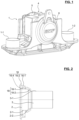
Figure 1 is a perspective front view of an axlebox assembly according to the invention, -
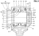
Figure 2 to 6 are views in axial cross section of the successive steps of assembling the axlebox ofFigure 1 , and -
Figure 7 is a perspective view of a rear cover according to the invention. - With reference to
Figures 1 and6 , anaxlebox 1 is intended to be attached to a bogie of a railway vehicle so as to support an axle attached to the wheels of the railway vehicle in a pivotal connection. - For the remainder of the description, we define the terms "front" and "rear" for the position of the axlebox in relation to the bogie. A front position is according to an axlebox side located axially towards the outside of the bogie, while a rear position is according to an axlebox side axially towards the inside of the bogie.
- The
axlebox 1 comprises two attachment ends 1-1 and 1-2 for attaching the axlebox to a rail vehicle bogie (not shown). This attachment can be implemented in a conventional manner, each end 1-1 and 1-2 being attached to one end of a rod of a shock absorber coupled to a suspension (not shown). - The axle comprises a
shaft 2, extended at its axial end by ajournal 3. The shaft is provided with an outer cylindrical surface 2-1, while thejournal 3 has an outer cylindrical surface 3-1 of smaller outer diameter than the shaft. A shaft shoulder 2-2 is thus formed at the base of thejournal 3. - The
axlebox 1 comprises ahousing 4 with ahousing body 5.Housing body 5 has a central cylindrical bore 5-1 of axis X5. Thehousing body 5 comprises a rear opening so as to receive theshaft 2. According to the invention, thehousing 4 further comprises a frontradial plate 6 closing the front side of thehousing body 5. An inner shoulder 5-2 is provided in the housing bore 5-1, said shoulder radially downwardly extending from the said housing bore 5-1, and being formed on the front side of thehousing 4. - To achieve the pivotal connection between the axle and the
axlebox 1, theaxlebox 1 further comprises arotary bearing 7 of axis X7.Bearing 7 comprises anouter ring 8 having two outer raceways 8-1, 8-2; twoinner ring elements spacer 13 axially interposed between the twoinner rings Figure 3 to 6 , therotary bearing 7 is of Tapered Roller Unit type, rollingelements bearing 7 is not dismountable after being mounted into theaxlebox 1. Alternatively, theouter ring 8 may be in two ring parts, each ring part being provided with a raceway. - Advantageously, the
rotary bearing 7 is further provided with rear sealing means 14 arranged between theouter ring 8 and theinner ring 9 at the rear axial end of thebearing 7, and front sealing means 15 arranged between theouter ring 8 and theinner ring 10 at the front axial end of thebearing 7. The bearing space between therings elements - The
outer ring 8 is mounted in the bore 5-1 in thehousing 4. Theouter ring 8 is in axial abutment against the inner shoulder 5-2 of housing bore 5-1 on front side. According to the invention, theouter ring 8 is in axial abutment against arear cover 16 on rear side, opposite to the shoulder 5-2. - As illustrated in
Figure 7 , therear cover 16 comprises a tubular portion 16-1 mounted in the housing bore 5-1, and defining a contact surface in axial abutment against a rear face of theouter ring 8. Therear cover 16 further comprises an annular radial outer collar 16-2 extending radially outwardly from the said tubular portion 16-1, said radial outer collar 16-2 being in axial abutment against a rear face of thehousing body 5. The annular radial outer collar is provided with a plurality of through openings 16-3, screws 17 axially traversing the said openings 16-3 for being screwed in corresponding threaded holes provided to the said rear face ofhousing body 5. Therear cover 16 further comprises an annular radial inner collar 16-4 extending radially inwardly from the said tubular portion 16-1, said radial inner collar 16-4 being radially in close vicinity with abacking ring 18. Inner and outer radial collars 16-2, 16-4 of therear cover 16 are of the same radial extension. Therear cover 16 is formed integral. Alternatively, the rear cover may formed by assembles parts. - The
outer ring 8 is axially pressed by the tubular portion 16-1 when therear cover 16 is screwed onto thehousing 4. Theouter ring 8 is then axially maintained between the shoulder 5-2 on front side and therear cover 16 on rear side within the housing bore 5-1 ofhousing 4. - The rear
inner ring 9, thespacer 13, and the frontinner ring 10 are axially fitted in series onto the outer cylindrical surface 3-1 of theshaft end journal 3. Theinner ring 9 is in axial abutment against abacking ring 18 on rear side. - The
backing ring 18 comprises an annular centering portion 18-1 mounted onto the outer cylindrical surface 2-1 of theshaft 2. Thebacking ring 18 further comprises an annular support portion 18-2 defining a first contact surface in axial abutment against the outer shoulder 2-2 of theshaft 2, and a second contact surface in axial abutment against theinner ring 9, said first and second contact surfaces being axially opposite to each other. Thebacking ring 18 is formed integral. - The front
inner ring 10 is in axial abutment against acap 19 fixed to the journal end.Cap 19 comprises a radial plate 19-1 with a plurality of through openings 19-2, screws 20 axially traversing the said openings 19-2 for being screwed in corresponding threaded holes provided to a front face ofjournal 3.Cap 19 further comprises a collar 19-3 defining a bore mounted onto the journal outer cylindrical surface 3-1, and a contact surface onto which theinner ring 10 is in axial abutment. - The
inner ring 9, thespacer 13, and theinner ring 10 are axially pressed by the collar 19-3 when thecap 19 is screwed onto thejournal 3. Theinner ring 9, thespacer 13, and theinner ring 10 are then axially maintained between thecap 19 on front side andbacking ring 18 on rear side onto theshaft end journal 3. - The present invention also relates to an assembly method of the
axlebox assembly 1 according to any of the preceding embodiments. - In a preliminary step, the two
inner rings spacer 13, theouter ring 8, and the rollingelements rotary bearing 7. Advantageously, the sealing means 14, 15 are further assembled on both axial sides of therotary bearing 7. Therotary bearing 7 is assembled in the production channels of the bearing manufacturer, and then shipped to the axlebox manufacturer. - In a first assembly step of the axlebox assembly, as illustrated in
Figure 2 , therear cover 16 is freely positioned onto ashaft 2 on rear side. Therear cover 16 is not fixed, it is only arranged around the shaft outer cylindrical surface 2-1. - The
backing ring 18 is then mounted on the shaft. The annular centering portion 18-1 is mounted onto the outer cylindrical surface 2-1 of theshaft 2. The annular support portion 18-2 is put in axial abutment against the outer shoulder 2-2 of theshaft 2. During this step, thebacking ring 18 is mounted in its final position onto theshaft 2. - In a second step illustrated in
Figure 3 , therotary bearing 7 is mounted onto the shaft end journal, the inner ring being press-fitted onto an outer cylindrical surface of thejournal 3. Theinner rings spacer 13 are press fitted onto the outer cylindrical surface 3-1 of thejournal 3. Theinner ring 9 is in axial abutment against the annular support portion 18-2 of thebacking ring 18 on rear side. During this step, therotary bearing 7 is mounted in its final position onto theshaft 2. - In a third step illustrated in
Figure 4 , thecap 19 is fixed onto thejournal end 3. Theinner ring 10 is in axial abutment against the collar 19-3 of saidcap 19 on front side.Screws 20 are axially traversing openings 19-2 provided on the radial plate 19-1 ofcap 19.Screws 20 are then screwed in corresponding threaded holes provided to a front face ofjournal 3. Theinner ring 9, thespacer 13, and theinner ring 10 are axially pressed by the collar 19-3 after thecap 19 is screwed onto thejournal 3. During this step, thecap 19 is mounted in its final position onto theshaft 2. - In a fourth step illustrated in
Figure 5 , thehousing 4 in mounted on therotary bearing 7. The central bore 5-1 of thehousing body 5 is fitted onto the outer cylindrical surface ofouter ring 8. The saidouter ring 8 is in axial abutment against the housing inner shoulder 5-2 on front side. The frontradial plate 6 ofhousing 4 covers thecap 6 and thejournal end 3 on front side. During this step, thehousing 4 is mounted in its final position onto theshaft 2. - In a fifth and final step illustrated in
Figure 6 , therear cover 16 is finally mounted and fixed onto thehousing 4. More precisely, the rear cover is slide axially from the intermediate position ofstep 1, and set in place with thehousing 4. The tubular portion 16-1 ofrear cover 16 is mounted in the housing bore 5-1. Theouter ring 8 is in axial abutment against the radial annular collar 16-2 of therear cover 16 on rear side.Screws 17 are axially traversing openings 16-3 provided on the said collar 16-3.Screws 17 are then screwed in corresponding threaded holes provided to the said rear face ofhousing body 5. During this step, therear cover 16 is mounted in its final position onto theshaft 2, and theaxlebox 1 is finally assembled. - Thanks to the invention, the
axlebox parts - Such an
axlebox assembly 1 includes anon-dismountable bearing unit 7 for a longer service life, and then requires les maintenance. - Furthermore, the technical features of the various embodiments can be combined with each other in whole or in part. In this way, the axlebox can be adapted in terms of cost, performance, and ease of implementation.
Claims (10)
- Axlebox assembly (1) comprising a housing (4), at least one rotary bearing (7), a backing ring (18), and a cap (19), wherein:- the housing (4) comprises a hollow body (5) having a bore (5-1) with a rear opening to accommodate a shaft end journal (3);- the rotary bearing (7) has a fixed outer ring (8) mounted in the housing bore (5-1), a rotating inner ring (9, 10) mountable on an outer cylindrical surface (3-1) of the shaft end journal (3), and at least one row of rolling elements (11, 12) interposed between the rings (8, 9, 10);- the inner ring (9, 10) is mounted in axial abutment against the backing ring (18) on rear side, and in axial abutment against the cap (19) on front side, the said cap (19) being fixed to the journal end (3);characterized in that:- the housing (4) is closed on front side by a front radial plate (6), the said cylindrical body (5) and front radial plate (6) being formed integral and defining an inner shoulder (5-2) extending radially inwardly in the bore (5-1) on front side;- the axlebox assembly (1) further comprises a rear cover (16) fixed to the housing cylindrical body (5) so as to close the rear opening; and- the outer ring (8) is mounted in axial abutment against the said rear cover (16) on rear side, and in axial abutment against the housing inner shoulder (5-2) on front side.
- Axlebox assembly (1) according to the claim 1, wherein the rotary bearing (7) comprises at least one outer ring (8) provided with two outer raceways (8-1, 8-2), two inner rings (9, 10) provided each with one inner raceway (9-1, 10-1), and two rows of rolling elements (11, 12), each row being supported in rotation by an outer raceway (8-1, 8-2) and an inner raceway (9-1, 10-1).
- Axlebox assembly according to any of the preceding claims, wherein the backing ring (18) comprises:- an annular centering portion (18-1) mounted onto an outer cylindrical surface (2-1) of the shaft (2);- an annular support portion (18-2) defining a first contact surface in axial abutment against an outer shoulder (2-2) of the shaft (2), and a second contact surface in axial abutment against an inner ring (9), said first and second contact surfaces being axially opposite to each other.
- Axlebox assembly according to any of the preceding claims, wherein the rear cover (16) comprises:- a tubular portion (16-1) mounted in the housing bore (5-1), and defining a contact surface in axial abutment against the outer ring (8); and- an annular radial outer collar (16-2) extending radially outwardly from the said tubular portion (16-1), said radial outer collar (16-2) being in axial abutment against a rear face of the housing body (5).
- Axlebox assembly (1) according to the claim 4, wherein the annular radial outer collar (16-2) is provided with a plurality of through openings (16-3), screws (17) axially traversing the said openings (16-3) for being screwed in corresponding threaded holes provided to the said rear face of housing body (5).
- Axlebox assembly (1) according to the claim 4 or 5, wherein the rear cover (16) further comprises an annular radial inner collar (16-4) extending radially inwardly from the said tubular portion (16-1), said radial inner collar (16-4) being radially in close vicinity with the backing ring (18).
- Axlebox assembly (1) according to the claim 6, wherein inner and outer radial collars (16-2, 16-4) of the rear cover (16) are of the same radial extension.
- Axlebox assembly (1) according to any of the claims 4 to 7, wherein the rear cover (16) is formed integral.
- Railway vehicle bogie, comprising at least one axle provided with a shaft (2), and at least one axlebox assembly (1) according to any of the preceding claims and mounted on one end of the shaft (2).
- Assembly method of an axlebox assembly (1) according to any of the preceding claims, and comprising the successive steps:- in a preliminary step, the inner ring (9, 10), the outer ring (8) and the rolling elements (11, 12) are assembled to form the rotary bearing (7);- in a first assembly step, the rear cover (16) is freely positioned onto the shaft (2) on rear side, and the backing ring (18) is then mounted on the shaft (2);- in a second step, the rotary bearing (7) is mounted onto the shaft end journal (3), the inner ring (9, 10) being press-fitted onto an outer cylindrical surface (3-1) of the journal (3), the said inner ring (9) being in axial abutment against the backing ring (18) on rear side;- in a third step, the cap (19) is fixed onto the journal end (3), the inner ring (10) being in axial abutment against the said cap (19) on front side;- in a fourth step, the housing (4) in mounted on the rotary bearing (7), the outer ring (8) being fitted in the housing bore (5-1) of housing body (5), the outer ring (8) being in axial abutment against the housing inner shoulder (5-2) on front side, the front radial plate (6) of housing covering the cap (19) and the journal end (3) on front side; and- in a fifth and final step, the rear cover (16) is mounted and fixed onto the housing (4), the outer ring (8) being in axial abutment against the rear cover (16) on rear side.
Applications Claiming Priority (1)
| Application Number | Priority Date | Filing Date | Title |
|---|---|---|---|
| DE102023200241.8A DE102023200241A1 (en) | 2023-01-12 | 2023-01-12 | Axle bearing assembly and method for assembling such an assembly |
Publications (1)
| Publication Number | Publication Date |
|---|---|
| EP4400383A1 true EP4400383A1 (en) | 2024-07-17 |
Family
ID=89430589
Family Applications (1)
| Application Number | Title | Priority Date | Filing Date |
|---|---|---|---|
| EP23218771.6A Pending EP4400383A1 (en) | 2023-01-12 | 2023-12-20 | Axlebox assembly, and assembly method of such an assembly |
Country Status (2)
| Country | Link |
|---|---|
| EP (1) | EP4400383A1 (en) |
| DE (1) | DE102023200241A1 (en) |
Citations (4)
| Publication number | Priority date | Publication date | Assignee | Title |
|---|---|---|---|---|
| US1966923A (en) * | 1929-11-11 | 1934-07-17 | Symington Co | Journal box |
| US2486123A (en) * | 1944-07-15 | 1949-10-25 | American Steel Foundries | Journal connection |
| US3869180A (en) * | 1971-09-30 | 1975-03-04 | Roulements Soc Nouvelle | Railway journal box bearing race mounting |
| EP2712784A1 (en) * | 2012-09-28 | 2014-04-02 | Jtekt Corporation | Bearing unit for railway vehicle |
-
2023
- 2023-01-12 DE DE102023200241.8A patent/DE102023200241A1/en active Pending
- 2023-12-20 EP EP23218771.6A patent/EP4400383A1/en active Pending
Patent Citations (4)
| Publication number | Priority date | Publication date | Assignee | Title |
|---|---|---|---|---|
| US1966923A (en) * | 1929-11-11 | 1934-07-17 | Symington Co | Journal box |
| US2486123A (en) * | 1944-07-15 | 1949-10-25 | American Steel Foundries | Journal connection |
| US3869180A (en) * | 1971-09-30 | 1975-03-04 | Roulements Soc Nouvelle | Railway journal box bearing race mounting |
| EP2712784A1 (en) * | 2012-09-28 | 2014-04-02 | Jtekt Corporation | Bearing unit for railway vehicle |
Also Published As
| Publication number | Publication date |
|---|---|
| DE102023200241A1 (en) | 2024-07-18 |
Similar Documents
| Publication | Publication Date | Title |
|---|---|---|
| US6135643A (en) | Hub unit bearing assembly and a method of making the same | |
| US10563693B2 (en) | Hub-bearing unit configured for mounting on the knuckle of a suspension | |
| CN103448467B (en) | Asymmetric hub unit | |
| US5385413A (en) | Bearing assembly with axial retention | |
| CN102267336A (en) | Wheel hub assembly | |
| US10562350B2 (en) | Axle wheel end axial thrust assembly | |
| KR20030036170A (en) | Wheel mounting with a bearing race embedded in a cast component | |
| CA1084569A (en) | Wheel mounting | |
| US3844631A (en) | Unitized thrust bearing and interlocking seal assembly therefor | |
| US4900166A (en) | Taper roller bearings for vehicle wheels | |
| EP2965922A1 (en) | Flanged hub-bearing unit | |
| US7699405B2 (en) | Vehicle wheel end assemblies and methods of assembly thereof | |
| US3741614A (en) | Roller bearings | |
| US20060051006A1 (en) | Rolling bearing arrangement | |
| JPH0328003A (en) | Bearing device for wheel hub | |
| US20100027931A1 (en) | Wheel end support bearing | |
| US20100150488A1 (en) | Bearing assembly | |
| US11794522B2 (en) | Axle wheel end axial thrust assembly | |
| US6557947B1 (en) | Three quarter floating automotive axle | |
| US11230143B2 (en) | Hub-bearing assembly for vehicles | |
| WO1995013198A1 (en) | Wheel bearing arrangements | |
| US3397021A (en) | Axle bearing construction | |
| EP0733494A2 (en) | Bearing assembly for axles of industrial vehicles | |
| WO2003089256A1 (en) | Method of assembling a package bearing and an assembly tool therefore | |
| WO2016040831A1 (en) | Axle wheel end axial thrust assembly |
Legal Events
| Date | Code | Title | Description |
|---|---|---|---|
| PUAI | Public reference made under article 153(3) epc to a published international application that has entered the european phase |
Free format text: ORIGINAL CODE: 0009012 |
|
| STAA | Information on the status of an ep patent application or granted ep patent |
Free format text: STATUS: THE APPLICATION HAS BEEN PUBLISHED |
|
| AK | Designated contracting states |
Kind code of ref document: A1 Designated state(s): AL AT BE BG CH CY CZ DE DK EE ES FI FR GB GR HR HU IE IS IT LI LT LU LV MC ME MK MT NL NO PL PT RO RS SE SI SK SM TR |
|
| STAA | Information on the status of an ep patent application or granted ep patent |
Free format text: STATUS: REQUEST FOR EXAMINATION WAS MADE |
|
| 17P | Request for examination filed |
Effective date: 20241223 |