EP4400344A1 - Liftgate metallic reinforcement thermal joining to the thermoplastic inner panel - Google Patents
Liftgate metallic reinforcement thermal joining to the thermoplastic inner panel Download PDFInfo
- Publication number
- EP4400344A1 EP4400344A1 EP23217356.7A EP23217356A EP4400344A1 EP 4400344 A1 EP4400344 A1 EP 4400344A1 EP 23217356 A EP23217356 A EP 23217356A EP 4400344 A1 EP4400344 A1 EP 4400344A1
- Authority
- EP
- European Patent Office
- Prior art keywords
- lift gate
- reinforcement bracket
- gate panel
- panel
- aperture
- Prior art date
- Legal status (The legal status is an assumption and is not a legal conclusion. Google has not performed a legal analysis and makes no representation as to the accuracy of the status listed.)
- Pending
Links
Images


Classifications
-
- B—PERFORMING OPERATIONS; TRANSPORTING
- B60—VEHICLES IN GENERAL
- B60J—WINDOWS, WINDSCREENS, NON-FIXED ROOFS, DOORS, OR SIMILAR DEVICES FOR VEHICLES; REMOVABLE EXTERNAL PROTECTIVE COVERINGS SPECIALLY ADAPTED FOR VEHICLES
- B60J5/00—Doors
- B60J5/10—Doors arranged at the vehicle rear
- B60J5/101—Doors arranged at the vehicle rear for non-load transporting vehicles, i.e. family cars including vans
- B60J5/107—Doors arranged at the vehicle rear for non-load transporting vehicles, i.e. family cars including vans constructional details, e.g. about door frame, panels, materials used, reinforcements
-
- B—PERFORMING OPERATIONS; TRANSPORTING
- B29—WORKING OF PLASTICS; WORKING OF SUBSTANCES IN A PLASTIC STATE IN GENERAL
- B29C—SHAPING OR JOINING OF PLASTICS; SHAPING OF MATERIAL IN A PLASTIC STATE, NOT OTHERWISE PROVIDED FOR; AFTER-TREATMENT OF THE SHAPED PRODUCTS, e.g. REPAIRING
- B29C65/00—Joining or sealing of preformed parts, e.g. welding of plastics materials; Apparatus therefor
- B29C65/02—Joining or sealing of preformed parts, e.g. welding of plastics materials; Apparatus therefor by heating, with or without pressure
- B29C65/44—Joining a heated non plastics element to a plastics element
- B29C65/46—Joining a heated non plastics element to a plastics element heated by induction
-
- B—PERFORMING OPERATIONS; TRANSPORTING
- B29—WORKING OF PLASTICS; WORKING OF SUBSTANCES IN A PLASTIC STATE IN GENERAL
- B29C—SHAPING OR JOINING OF PLASTICS; SHAPING OF MATERIAL IN A PLASTIC STATE, NOT OTHERWISE PROVIDED FOR; AFTER-TREATMENT OF THE SHAPED PRODUCTS, e.g. REPAIRING
- B29C65/00—Joining or sealing of preformed parts, e.g. welding of plastics materials; Apparatus therefor
- B29C65/56—Joining or sealing of preformed parts, e.g. welding of plastics materials; Apparatus therefor using mechanical means or mechanical connections, e.g. form-fits
- B29C65/64—Joining a non-plastics element to a plastics element, e.g. by force
- B29C65/645—Joining a non-plastics element to a plastics element, e.g. by force using friction or ultrasonic vibrations
-
- B—PERFORMING OPERATIONS; TRANSPORTING
- B29—WORKING OF PLASTICS; WORKING OF SUBSTANCES IN A PLASTIC STATE IN GENERAL
- B29C—SHAPING OR JOINING OF PLASTICS; SHAPING OF MATERIAL IN A PLASTIC STATE, NOT OTHERWISE PROVIDED FOR; AFTER-TREATMENT OF THE SHAPED PRODUCTS, e.g. REPAIRING
- B29C66/00—General aspects of processes or apparatus for joining preformed parts
- B29C66/01—General aspects dealing with the joint area or with the area to be joined
- B29C66/05—Particular design of joint configurations
- B29C66/10—Particular design of joint configurations particular design of the joint cross-sections
- B29C66/11—Joint cross-sections comprising a single joint-segment, i.e. one of the parts to be joined comprising a single joint-segment in the joint cross-section
- B29C66/112—Single lapped joints
- B29C66/1122—Single lap to lap joints, i.e. overlap joints
-
- B—PERFORMING OPERATIONS; TRANSPORTING
- B29—WORKING OF PLASTICS; WORKING OF SUBSTANCES IN A PLASTIC STATE IN GENERAL
- B29C—SHAPING OR JOINING OF PLASTICS; SHAPING OF MATERIAL IN A PLASTIC STATE, NOT OTHERWISE PROVIDED FOR; AFTER-TREATMENT OF THE SHAPED PRODUCTS, e.g. REPAIRING
- B29C66/00—General aspects of processes or apparatus for joining preformed parts
- B29C66/01—General aspects dealing with the joint area or with the area to be joined
- B29C66/05—Particular design of joint configurations
- B29C66/20—Particular design of joint configurations particular design of the joint lines, e.g. of the weld lines
- B29C66/21—Particular design of joint configurations particular design of the joint lines, e.g. of the weld lines said joint lines being formed by a single dot or dash or by several dots or dashes, i.e. spot joining or spot welding
-
- B—PERFORMING OPERATIONS; TRANSPORTING
- B29—WORKING OF PLASTICS; WORKING OF SUBSTANCES IN A PLASTIC STATE IN GENERAL
- B29C—SHAPING OR JOINING OF PLASTICS; SHAPING OF MATERIAL IN A PLASTIC STATE, NOT OTHERWISE PROVIDED FOR; AFTER-TREATMENT OF THE SHAPED PRODUCTS, e.g. REPAIRING
- B29C66/00—General aspects of processes or apparatus for joining preformed parts
- B29C66/01—General aspects dealing with the joint area or with the area to be joined
- B29C66/05—Particular design of joint configurations
- B29C66/303—Particular design of joint configurations the joint involving an anchoring effect
- B29C66/3032—Particular design of joint configurations the joint involving an anchoring effect making use of protrusions or cavities belonging to at least one of the parts to be joined
- B29C66/30321—Particular design of joint configurations the joint involving an anchoring effect making use of protrusions or cavities belonging to at least one of the parts to be joined making use of protrusions belonging to at least one of the parts to be joined
-
- B—PERFORMING OPERATIONS; TRANSPORTING
- B29—WORKING OF PLASTICS; WORKING OF SUBSTANCES IN A PLASTIC STATE IN GENERAL
- B29C—SHAPING OR JOINING OF PLASTICS; SHAPING OF MATERIAL IN A PLASTIC STATE, NOT OTHERWISE PROVIDED FOR; AFTER-TREATMENT OF THE SHAPED PRODUCTS, e.g. REPAIRING
- B29C66/00—General aspects of processes or apparatus for joining preformed parts
- B29C66/50—General aspects of joining tubular articles; General aspects of joining long products, i.e. bars or profiled elements; General aspects of joining single elements to tubular articles, hollow articles or bars; General aspects of joining several hollow-preforms to form hollow or tubular articles
- B29C66/51—Joining tubular articles, profiled elements or bars; Joining single elements to tubular articles, hollow articles or bars; Joining several hollow-preforms to form hollow or tubular articles
- B29C66/53—Joining single elements to tubular articles, hollow articles or bars
- B29C66/532—Joining single elements to the wall of tubular articles, hollow articles or bars
-
- B—PERFORMING OPERATIONS; TRANSPORTING
- B29—WORKING OF PLASTICS; WORKING OF SUBSTANCES IN A PLASTIC STATE IN GENERAL
- B29C—SHAPING OR JOINING OF PLASTICS; SHAPING OF MATERIAL IN A PLASTIC STATE, NOT OTHERWISE PROVIDED FOR; AFTER-TREATMENT OF THE SHAPED PRODUCTS, e.g. REPAIRING
- B29C66/00—General aspects of processes or apparatus for joining preformed parts
- B29C66/50—General aspects of joining tubular articles; General aspects of joining long products, i.e. bars or profiled elements; General aspects of joining single elements to tubular articles, hollow articles or bars; General aspects of joining several hollow-preforms to form hollow or tubular articles
- B29C66/51—Joining tubular articles, profiled elements or bars; Joining single elements to tubular articles, hollow articles or bars; Joining several hollow-preforms to form hollow or tubular articles
- B29C66/54—Joining several hollow-preforms, e.g. half-shells, to form hollow articles, e.g. for making balls, containers; Joining several hollow-preforms, e.g. half-cylinders, to form tubular articles
-
- B—PERFORMING OPERATIONS; TRANSPORTING
- B29—WORKING OF PLASTICS; WORKING OF SUBSTANCES IN A PLASTIC STATE IN GENERAL
- B29C—SHAPING OR JOINING OF PLASTICS; SHAPING OF MATERIAL IN A PLASTIC STATE, NOT OTHERWISE PROVIDED FOR; AFTER-TREATMENT OF THE SHAPED PRODUCTS, e.g. REPAIRING
- B29C66/00—General aspects of processes or apparatus for joining preformed parts
- B29C66/70—General aspects of processes or apparatus for joining preformed parts characterised by the composition, physical properties or the structure of the material of the parts to be joined; Joining with non-plastics material
- B29C66/72—General aspects of processes or apparatus for joining preformed parts characterised by the composition, physical properties or the structure of the material of the parts to be joined; Joining with non-plastics material characterised by the structure of the material of the parts to be joined
- B29C66/721—Fibre-reinforced materials
-
- B—PERFORMING OPERATIONS; TRANSPORTING
- B29—WORKING OF PLASTICS; WORKING OF SUBSTANCES IN A PLASTIC STATE IN GENERAL
- B29C—SHAPING OR JOINING OF PLASTICS; SHAPING OF MATERIAL IN A PLASTIC STATE, NOT OTHERWISE PROVIDED FOR; AFTER-TREATMENT OF THE SHAPED PRODUCTS, e.g. REPAIRING
- B29C66/00—General aspects of processes or apparatus for joining preformed parts
- B29C66/70—General aspects of processes or apparatus for joining preformed parts characterised by the composition, physical properties or the structure of the material of the parts to be joined; Joining with non-plastics material
- B29C66/73—General aspects of processes or apparatus for joining preformed parts characterised by the composition, physical properties or the structure of the material of the parts to be joined; Joining with non-plastics material characterised by the intensive physical properties of the material of the parts to be joined, by the optical properties of the material of the parts to be joined, by the extensive physical properties of the parts to be joined, by the state of the material of the parts to be joined or by the material of the parts to be joined being a thermoplastic or a thermoset
- B29C66/739—General aspects of processes or apparatus for joining preformed parts characterised by the composition, physical properties or the structure of the material of the parts to be joined; Joining with non-plastics material characterised by the intensive physical properties of the material of the parts to be joined, by the optical properties of the material of the parts to be joined, by the extensive physical properties of the parts to be joined, by the state of the material of the parts to be joined or by the material of the parts to be joined being a thermoplastic or a thermoset characterised by the material of the parts to be joined being a thermoplastic or a thermoset
- B29C66/7392—General aspects of processes or apparatus for joining preformed parts characterised by the composition, physical properties or the structure of the material of the parts to be joined; Joining with non-plastics material characterised by the intensive physical properties of the material of the parts to be joined, by the optical properties of the material of the parts to be joined, by the extensive physical properties of the parts to be joined, by the state of the material of the parts to be joined or by the material of the parts to be joined being a thermoplastic or a thermoset characterised by the material of the parts to be joined being a thermoplastic or a thermoset characterised by the material of at least one of the parts being a thermoplastic
-
- B—PERFORMING OPERATIONS; TRANSPORTING
- B29—WORKING OF PLASTICS; WORKING OF SUBSTANCES IN A PLASTIC STATE IN GENERAL
- B29C—SHAPING OR JOINING OF PLASTICS; SHAPING OF MATERIAL IN A PLASTIC STATE, NOT OTHERWISE PROVIDED FOR; AFTER-TREATMENT OF THE SHAPED PRODUCTS, e.g. REPAIRING
- B29C66/00—General aspects of processes or apparatus for joining preformed parts
- B29C66/70—General aspects of processes or apparatus for joining preformed parts characterised by the composition, physical properties or the structure of the material of the parts to be joined; Joining with non-plastics material
- B29C66/74—Joining plastics material to non-plastics material
- B29C66/742—Joining plastics material to non-plastics material to metals or their alloys
-
- B—PERFORMING OPERATIONS; TRANSPORTING
- B29—WORKING OF PLASTICS; WORKING OF SUBSTANCES IN A PLASTIC STATE IN GENERAL
- B29C—SHAPING OR JOINING OF PLASTICS; SHAPING OF MATERIAL IN A PLASTIC STATE, NOT OTHERWISE PROVIDED FOR; AFTER-TREATMENT OF THE SHAPED PRODUCTS, e.g. REPAIRING
- B29C66/00—General aspects of processes or apparatus for joining preformed parts
- B29C66/80—General aspects of machine operations or constructions and parts thereof
- B29C66/83—General aspects of machine operations or constructions and parts thereof characterised by the movement of the joining or pressing tools
- B29C66/832—Reciprocating joining or pressing tools
- B29C66/8322—Joining or pressing tools reciprocating along one axis
-
- B—PERFORMING OPERATIONS; TRANSPORTING
- B60—VEHICLES IN GENERAL
- B60J—WINDOWS, WINDSCREENS, NON-FIXED ROOFS, DOORS, OR SIMILAR DEVICES FOR VEHICLES; REMOVABLE EXTERNAL PROTECTIVE COVERINGS SPECIALLY ADAPTED FOR VEHICLES
- B60J5/00—Doors
- B60J5/10—Doors arranged at the vehicle rear
- B60J5/101—Doors arranged at the vehicle rear for non-load transporting vehicles, i.e. family cars including vans
-
- B—PERFORMING OPERATIONS; TRANSPORTING
- B62—LAND VEHICLES FOR TRAVELLING OTHERWISE THAN ON RAILS
- B62D—MOTOR VEHICLES; TRAILERS
- B62D27/00—Connections between superstructure or understructure sub-units
- B62D27/02—Connections between superstructure or understructure sub-units rigid
-
- B—PERFORMING OPERATIONS; TRANSPORTING
- B62—LAND VEHICLES FOR TRAVELLING OTHERWISE THAN ON RAILS
- B62D—MOTOR VEHICLES; TRAILERS
- B62D29/00—Superstructures, understructures, or sub-units thereof, characterised by the material thereof
- B62D29/001—Superstructures, understructures, or sub-units thereof, characterised by the material thereof characterised by combining metal and synthetic material
-
- B—PERFORMING OPERATIONS; TRANSPORTING
- B29—WORKING OF PLASTICS; WORKING OF SUBSTANCES IN A PLASTIC STATE IN GENERAL
- B29C—SHAPING OR JOINING OF PLASTICS; SHAPING OF MATERIAL IN A PLASTIC STATE, NOT OTHERWISE PROVIDED FOR; AFTER-TREATMENT OF THE SHAPED PRODUCTS, e.g. REPAIRING
- B29C66/00—General aspects of processes or apparatus for joining preformed parts
- B29C66/70—General aspects of processes or apparatus for joining preformed parts characterised by the composition, physical properties or the structure of the material of the parts to be joined; Joining with non-plastics material
- B29C66/71—General aspects of processes or apparatus for joining preformed parts characterised by the composition, physical properties or the structure of the material of the parts to be joined; Joining with non-plastics material characterised by the composition of the plastics material of the parts to be joined
-
- B—PERFORMING OPERATIONS; TRANSPORTING
- B29—WORKING OF PLASTICS; WORKING OF SUBSTANCES IN A PLASTIC STATE IN GENERAL
- B29C—SHAPING OR JOINING OF PLASTICS; SHAPING OF MATERIAL IN A PLASTIC STATE, NOT OTHERWISE PROVIDED FOR; AFTER-TREATMENT OF THE SHAPED PRODUCTS, e.g. REPAIRING
- B29C66/00—General aspects of processes or apparatus for joining preformed parts
- B29C66/70—General aspects of processes or apparatus for joining preformed parts characterised by the composition, physical properties or the structure of the material of the parts to be joined; Joining with non-plastics material
- B29C66/72—General aspects of processes or apparatus for joining preformed parts characterised by the composition, physical properties or the structure of the material of the parts to be joined; Joining with non-plastics material characterised by the structure of the material of the parts to be joined
- B29C66/721—Fibre-reinforced materials
- B29C66/7212—Fibre-reinforced materials characterised by the composition of the fibres
-
- B—PERFORMING OPERATIONS; TRANSPORTING
- B29—WORKING OF PLASTICS; WORKING OF SUBSTANCES IN A PLASTIC STATE IN GENERAL
- B29C—SHAPING OR JOINING OF PLASTICS; SHAPING OF MATERIAL IN A PLASTIC STATE, NOT OTHERWISE PROVIDED FOR; AFTER-TREATMENT OF THE SHAPED PRODUCTS, e.g. REPAIRING
- B29C66/00—General aspects of processes or apparatus for joining preformed parts
- B29C66/70—General aspects of processes or apparatus for joining preformed parts characterised by the composition, physical properties or the structure of the material of the parts to be joined; Joining with non-plastics material
- B29C66/74—Joining plastics material to non-plastics material
- B29C66/742—Joining plastics material to non-plastics material to metals or their alloys
- B29C66/7422—Aluminium or alloys of aluminium
-
- B—PERFORMING OPERATIONS; TRANSPORTING
- B29—WORKING OF PLASTICS; WORKING OF SUBSTANCES IN A PLASTIC STATE IN GENERAL
- B29C—SHAPING OR JOINING OF PLASTICS; SHAPING OF MATERIAL IN A PLASTIC STATE, NOT OTHERWISE PROVIDED FOR; AFTER-TREATMENT OF THE SHAPED PRODUCTS, e.g. REPAIRING
- B29C66/00—General aspects of processes or apparatus for joining preformed parts
- B29C66/70—General aspects of processes or apparatus for joining preformed parts characterised by the composition, physical properties or the structure of the material of the parts to be joined; Joining with non-plastics material
- B29C66/74—Joining plastics material to non-plastics material
- B29C66/742—Joining plastics material to non-plastics material to metals or their alloys
- B29C66/7428—Transition metals or their alloys
- B29C66/74283—Iron or alloys of iron, e.g. steel
-
- B—PERFORMING OPERATIONS; TRANSPORTING
- B60—VEHICLES IN GENERAL
- B60J—WINDOWS, WINDSCREENS, NON-FIXED ROOFS, DOORS, OR SIMILAR DEVICES FOR VEHICLES; REMOVABLE EXTERNAL PROTECTIVE COVERINGS SPECIALLY ADAPTED FOR VEHICLES
- B60J5/00—Doors
- B60J5/04—Doors arranged at the vehicle sides
- B60J5/048—Doors arranged at the vehicle sides characterised by the material
- B60J5/0481—Doors arranged at the vehicle sides characterised by the material plastic
Definitions
- the present invention relates to a method of joining metal reinforcements to thermoplastic liftgate inner panels using various thermal joining techniques.
- thermoplastic lift gates In the automotive field it has been desirable to produce exterior components out of polymeric material, rather than by forming the components out of metal.
- lift gates for a vehicle have traditionally been formed of stamped metal components.
- reinforcements used in thermoplastic lift gates are metal plates which are fastened to the interior portion of the lift gate, connecting the metal reinforcements at specific locations is accomplished using fasteners or adhesives.
- a reinforced lift gate panel arrangement that includes a lift gate panel formed of fiber filled polymer material.
- the lift gate panel has a structural side with a connection surface region.
- the arrangement further includes at least one reinforcement bracket with a panel contact side and a tool contact side with at least one aperture formed through the reinforcement bracket that extends from the panel contact side to the tool contact side.
- the at least one reinforcement bracket is connected to the lift gate panel using only the at least one mechanical lock and without adhesives. Also, in the present embodiment of the invention the at least one reinforcement bracket is connected to the lift gate panel using only the at least one mechanical lock and without threaded fasteners.
- a reinforced lift gate panel arrangement 10 that includes a lift gate panel 12 formed of fiber filled polymer material.
- the lift gate panel 12 has a structural side 14 two connection surface regions 16a, 16b. While two connection surface regions 16a, 16b are shown it is within the scope of this invention for there to be a lesser or greater number of connection surface regions depending on the needs of a particular application.
- the reinforced liftgate panel arrangement 10 further includes reinforcement bracket 18a, 18b each having a panel contact side 20a, 20b and a tool contact side 22a, 22b.
- Each reinforcement bracket 18a, 18b includes a number of connection regions 24a-i, 26a-i that each include apertures 28a-e formed through the respective reinforcement bracket 18a, 18b and extends from the panel contact side 20a, 20b to the tool contact side 22a, 22b.
- the connection surface regions 16a, 16b are shaped surfaces or regions on the structural side 14 of the lift gate panel 12 that allow all or a portion of the corresponding the reinforcement brackets 18a, 18b to have surface to surface contact with the structural side 14, so that a suitable mechanical connection can be formed. It is also within the scope of the invention for just each of the connection regions 24a-i, 26a-i to have surface to surface contact with the connection surface region 16a, 16b of the reinforcement bracket 18a, 18b.
- the present embodiment of the invention shows two once piece reinforcement brackets 18a, 18b it is within the scope of the invention for there to be a greater or lesser number of reinforcement brackets, or for them to be formed of multiple pieces.
- each of the connection regions 24a-i, 26a-i include apertures 28a-e totaling five in number. While five apertures are shown it is within the scope of the invention for a greater or lesser number of apertures to be used.
- a mechanical lock is between the reinforcement bracket 18a, 18b and the liftgate panel 12 is formed using the method described below.
- Fig. 2 is a cross sectional view of a mechanical lock 29, which would be formed at each of the apertures 28a-e of the connection regions 24a-i, 26a-i described above.
- the apertures 28a-e each have a draft angle 30a, 30b that is an angled edge of the material of the reinforcement bracket 18a, 18b.
- the fiber filled polymeric material of the lift gate panel 12 is melted in a localized region so that the draft angle 30a, 30b becomes embedded into the material of the lift gate panel 12 to form the mechanical lock 29 that is strengthened by the draft angle 30a, 30b providing more surface area and better embedding into the lift gate panel 12.
- the reinforcement brackets 18a, 18b are connected to the lift gate panel 12 using only the mechanical locks and without adhesives. Also, in the present embodiment of the invention the reinforcement bracket 18a, 18b are connected to the lift gate panel 12 using only the mechanical locks, without threaded fasteners.
- Another embodiment of the present invention is directed to a method of connecting the reinforcement brackets 18a, 18b to the lift gate panel 12 for a vehicle.
- the method includes the steps of providing the reinforcement bracket 18a, 18b having a panel contact side 20a, 20b and a tool contact side 22a, 22b.
- the reinforcement bracket 18a, 18b is formed of metal or alloy. Suitable material includes iron, steel and aluminum.
- the reinforcement bracket 18a, 18b includes at least one aperture 28a-e formed through the reinforcement bracket 18a, 18b that extends from the panel contact side 20a, 20b to the tool contact side 22a, 22b.
- the method further includes providing the lift gate panel 12 having a structural side 14 with the connection surface region 16a, 16b.
- the lift gate panel 12 is formed of long fiber filled polymeric material.
- the lift gate panel 12 can be an inner panel, middle panel or outer panel of a lift gate.
- Suitable polymers for forming the liftgate inner panel include ABS, polypropylene and thermoplastic olefin materials, while suitable long fibers includes glass fibers, carbon fibers, or any other type of filler material.
- the method further includes providing a lock forming tool 32 with an output surface 34.
- the lock forming tool 32 can take many forms depending on the requirements of a particular application. However, it is within the scope of this invention for the lock forming tool 32 to include, but not be limited to one of an ultrasonic welding tool, a microwave welding tool, an induction heating tool, a heat staking tool, and combinations thereof where several tools are used in unison or succession.
- the method continues with a first step of placing the reinforcement bracket 18a, 18b against the structural side 14 of the lift gate panel 12, so that the panel contact side 20a, 20b is in contact with the connection surface region 16a, 16b of the lift gate panel 12. Then a step of positioning the lock forming tool 32 so that the output surface is in contact with the tool contact side of the reinforcement bracket is conducted. During this step, the output surface 34 surrounds the apertures 28a-e of the reinforcement bracket 18a, 18b.
- a step of energizing the lock forming tool 32 occurs. During this step heating of a portion of the reinforcement bracket 18a, 18b and a portion of the lift gate panel 12 occurs. A localized molten unit of molten polymer of the lift gate panel 12 is formed and a part of the molten unit flows into the at least one aperture 28a-e of the reinforcement bracket. Then a step during a step the lock forming tool 32 is deenergized and removed from the reinforcement bracket 18a, 18b. At a step, the molten unit is cured to form a mechanical lock 29 that connects the reinforcement bracket to the lift gate inner panel.
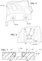
- Fig. 7 is an enlarged cross sectional side elevational view of an alternative mechanical connection between a reinforcement bracket and a liftgate panel according to another embodiment of the invention.
- a mechanical lock 129 which would be formed at each of the apertures 28a-e of the connection regions 24a-i, 26a-i described above.
- the apertures 28a-e each have a concave draft angle 130a, 130b where a portion of the metal around the apertures 28a-e is curved back or bend backward to form a collar in the material of a reinforcement bracket 118, which can be used in place of reinforcement bracket 18a, 18b discussed above.
- the fiber filled polymeric material of the lift gate panel 12 is melted into a fixing region 131a, 131b and the concave draft angle 130a, 130b becomes embedded into the material of the lift gate panel 12 to form the mechanical lock 129, that is strengthened by the concave draft angle 130a, 130b providing more surface area and better embedding into the lift gate panel.
Landscapes
- Engineering & Computer Science (AREA)
- Mechanical Engineering (AREA)
- Chemical & Material Sciences (AREA)
- Combustion & Propulsion (AREA)
- Transportation (AREA)
- Architecture (AREA)
- Structural Engineering (AREA)
- Body Structure For Vehicles (AREA)
Abstract
Description
- The present invention relates to a method of joining metal reinforcements to thermoplastic liftgate inner panels using various thermal joining techniques.
- In the automotive field it has been desirable to produce exterior components out of polymeric material, rather than by forming the components out of metal. In particular lift gates for a vehicle have traditionally been formed of stamped metal components. More recently there have been several different lift gates produced that are formed of thermoplastic material. This provides a substantial reduction in weight, as well as providing greater variety in style and design, sense the thermoplastic material is able to be more easily formed with greater angles, forming the lift gate or other components out of thermoplastics can sometimes require the attachment of reinforcements. Typically, reinforcements used in thermoplastic lift gates are metal plates which are fastened to the interior portion of the lift gate, connecting the metal reinforcements at specific locations is accomplished using fasteners or adhesives. However, this is problematic because the use of fasteners increases production time and complexity, while using adhesives increases costs and creates recycling difficulties, since the adhesive material is adhered to the metal reinforcement. It is desirable to develop new methods for connecting the reinforcements at desired locations on the thermoplastic lift gate.
- A reinforced lift gate panel arrangement that includes a lift gate panel formed of fiber filled polymer material. The lift gate panel has a structural side with a connection surface region. The arrangement further includes at least one reinforcement bracket with a panel contact side and a tool contact side with at least one aperture formed through the reinforcement bracket that extends from the panel contact side to the tool contact side. There is at least one mechanical lock formed between the lift gate panel and the reinforcement bracket. The mechanical lock is formed by a portion of the fiber filled polymer material curing in the at least one aperture of the reinforcement bracket.
- In the present embodiment of the invention the at least one reinforcement bracket is connected to the lift gate panel using only the at least one mechanical lock and without adhesives. Also, in the present embodiment of the invention the at least one reinforcement bracket is connected to the lift gate panel using only the at least one mechanical lock and without threaded fasteners.
- Further areas of applicability of the present invention will become apparent from the detailed description provided hereinafter. It should be understood that the detailed description and specific examples, while indicating the preferred embodiment of the invention, are intended for purposes of illustration only and are not intended to limit the scope of the invention.
- The present invention will become more fully understood from the detailed description and the accompanying drawings, wherein:
-
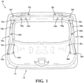
Fig. 1 is a rear side elevational view of a liftgate arrangement according to one embodiment of the present invention. -
Fig. 2 is a side elevational schematic view of a method of forming a mechanical connection between a reinforcement bracket to a liftgate panel. -
Fig. 3 is an enlarged cross sectional side elevational view of a reinforcement bracket connected to a lift gate panel. -
Fig. 4 is a side elevational view of a reinforcement bracket according to one embodiment of the present invention. -
Fig. 5 an enlarged side perspective of a portion of the reinforcement bracket. -
Fig. 6 is an enlarged elevational view of one group of apertures formed in the reinforcement bracket. -
Fig. 7 is an enlarged cross sectional side elevational view of an alternative mechanical connection between a reinforcement bracket and a liftgate panel according to another embodiment of the invention. - The following description of the preferred embodiments is merely exemplary in nature and is in no way intended to limit the invention, its application, or uses.
- Referring now to the
figures 1 and2-6 there is shown a reinforced liftgate panel arrangement 10 that includes alift gate panel 12 formed of fiber filled polymer material. Thelift gate panel 12 has astructural side 14 twoconnection surface regions connection surface regions liftgate panel arrangement 10 further includesreinforcement bracket panel contact side tool contact side reinforcement bracket connection regions 24a-i, 26a-i that each includeapertures 28a-e formed through therespective reinforcement bracket panel contact side tool contact side connection surface regions structural side 14 of thelift gate panel 12 that allow all or a portion of the corresponding thereinforcement brackets structural side 14, so that a suitable mechanical connection can be formed. It is also within the scope of the invention for just each of theconnection regions 24a-i, 26a-i to have surface to surface contact with theconnection surface region reinforcement bracket piece reinforcement brackets - As described above each of the
connection regions 24a-i, 26a-i includeapertures 28a-e totaling five in number. While five apertures are shown it is within the scope of the invention for a greater or lesser number of apertures to be used. At each aperture, a mechanical lock is between thereinforcement bracket liftgate panel 12 is formed using the method described below.Fig. 2 is a cross sectional view of amechanical lock 29, which would be formed at each of theapertures 28a-e of theconnection regions 24a-i, 26a-i described above. As shown theapertures 28a-e each have adraft angle reinforcement bracket lift gate panel 12 is melted in a localized region so that thedraft angle lift gate panel 12 to form themechanical lock 29 that is strengthened by thedraft angle lift gate panel 12. - In the present embodiment of the invention the
reinforcement brackets lift gate panel 12 using only the mechanical locks and without adhesives. Also, in the present embodiment of the invention thereinforcement bracket lift gate panel 12 using only the mechanical locks, without threaded fasteners. - Another embodiment of the present invention is directed to a method of connecting the
reinforcement brackets lift gate panel 12 for a vehicle. The method includes the steps of providing thereinforcement bracket panel contact side tool contact side reinforcement bracket reinforcement bracket aperture 28a-e formed through thereinforcement bracket panel contact side tool contact side lift gate panel 12 having astructural side 14 with theconnection surface region lift gate panel 12 is formed of long fiber filled polymeric material. Thelift gate panel 12 can be an inner panel, middle panel or outer panel of a lift gate. Suitable polymers for forming the liftgate inner panel include ABS, polypropylene and thermoplastic olefin materials, while suitable long fibers includes glass fibers, carbon fibers, or any other type of filler material. - The method further includes providing a
lock forming tool 32 with anoutput surface 34. Thelock forming tool 32 can take many forms depending on the requirements of a particular application. However, it is within the scope of this invention for thelock forming tool 32 to include, but not be limited to one of an ultrasonic welding tool, a microwave welding tool, an induction heating tool, a heat staking tool, and combinations thereof where several tools are used in unison or succession. - The method continues with a first step of placing the
reinforcement bracket structural side 14 of thelift gate panel 12, so that thepanel contact side connection surface region lift gate panel 12. Then a step of positioning thelock forming tool 32 so that the output surface is in contact with the tool contact side of the reinforcement bracket is conducted. During this step, theoutput surface 34 surrounds theapertures 28a-e of thereinforcement bracket - Once the
lock forming tool 32 is in position, a step of energizing thelock forming tool 32 occurs. During this step heating of a portion of thereinforcement bracket lift gate panel 12 occurs. A localized molten unit of molten polymer of thelift gate panel 12 is formed and a part of the molten unit flows into the at least oneaperture 28a-e of the reinforcement bracket. Then a step during a step thelock forming tool 32 is deenergized and removed from thereinforcement bracket mechanical lock 29 that connects the reinforcement bracket to the lift gate inner panel. -
Fig. 7 is an enlarged cross sectional side elevational view of an alternative mechanical connection between a reinforcement bracket and a liftgate panel according to another embodiment of the invention. As shown inFig.7 there is a cross sectional view of amechanical lock 129, which would be formed at each of theapertures 28a-e of theconnection regions 24a-i, 26a-i described above. Theapertures 28a-e each have aconcave draft angle apertures 28a-e is curved back or bend backward to form a collar in the material of areinforcement bracket 118, which can be used in place ofreinforcement bracket lift gate panel 12 is melted into a fixingregion concave draft angle lift gate panel 12 to form themechanical lock 129, that is strengthened by theconcave draft angle - The description of the invention is merely exemplary in nature and, thus, variations that do not depart from the gist of the invention are intended to be within the scope of the invention. Such variations are not to be regarded as a departure from the spirit and scope of the invention.
Claims (11)
- A reinforced lift gate panel (12) arrangement (10) comprising:a lift gate panel (12) formed of fiber filled polymer material and having a structural side (14) with a connection surface region (16a, 16b);at least one reinforcement bracket (18a, 18b) with a panel contact side (20a, 20b) and a tool contact side (22a, 22b), the reinforcement bracket (18a, 18b) includes at least one aperture (28a-e) formed through the reinforcement bracket (18a, 18b) that extends from the panel contact side (20a, 20b) to the tool contact side (22a, 22b);at least one mechanical lock (29; 129) formed between the lift gate panel (12) and the reinforcement bracket (18a, 18b), wherein the mechanical lock (29; 129) is formed by a portion of the fiber filled polymer material curing in the at least one aperture (28a-e) of the reinforcement bracket (18a, 18b).
- The reinforced lift gate panel (12) arrangement (10) of claim 1, wherein the at least one aperture (28a-e) further comprises a draft angle surface (30a, 30b; 130a, 130b) that the portion of the fiber filled material curing of the lift gate panel (12) extends into the molten unit and forms part of the mechanical lock (29; 129).
- The reinforced lift gate panel (12) arrangement (10) of claim 1 or 2, wherein the at least one reinforcement bracket (18a, 18b) is connected to the lift gate panel (12) using only the at least one mechanical lock (29; 129) and without adhesives.
- The reinforced lift gate panel (12) arrangement (10) of any one of claims 1 to 3, wherein the at least one reinforcement bracket (18a, 18b) is connected to the lift gate panel (12) using only the at least one mechanical lock (29; 129) and without threaded fasteners.
- The reinforced lift gate panel (12) arrangement (10) of any one of claims 1 to 4, wherein the lift gate panel (12) is an inner panel of a lift gate.
- The reinforced lift gate panel (12) arrangement (10) of any one of claims 1 to 5, wherein the at least one reinforcement bracket (18a, 18b) is metal or alloy.
- The reinforced lift gate panel (12) arrangement (10) of any one of claims 1 to 6, wherein the at least one aperture (28a-e) further comprises:a concave draft angle (130a, 130b) where a portion of the metal around the at least one aperture (28a-e) forms a collar in the material of the reinforcement bracket (18a, 18b), anda fixing region (131a, 131b) and the concave draft angle (130a, 130b) becomes embedded into the material of the lift gate panel (12) to form the mechanical lock (129), which is strengthened by the concave draft angle (130a, 130b) providing more surface area and better embedding into the lift gate panel (12).
- A method of connecting a reinforcement bracket (18a, 18b) to a lift gate panel (12) for a vehicle comprising the steps of:providing a reinforcement bracket (18a, 18b) with a panel contact side (20a, 20b) and a tool contact side (22a, 22b), the reinforcement bracket (18a, 18b) includes at least one aperture (28a-e) formed through the reinforcement bracket (18a, 18b) that extends from the panel contact side (20a, 20b) to the tool contact side (22a, 22b);providing a lift gate panel (12) having a structural side (14) with a connection surface region (16a, 16b);providing a lock forming tool (32) with an output surface (34);placing the reinforcement bracket (18a, 18b) against the structural side (14) of the lift gate panel (12) so that the panel contact side (20a, 20b) is in contact with the connection surface region (16a, 16b) of the lift gate panel (12);positioning the lock forming tool (32) so that the output surface (34) is in contact with the tool contact side (22a, 22b) of the reinforcement bracket (18a, 18b), wherein the output surface (34) surrounds the at least one aperture (28a-e) of the reinforcement bracket (18a, 18b);energizing the lock forming tool (32) and heating a portion of the lift gate panel (12) to form a localized molten unit, wherein a part of the molten unit flows into the at least one aperture (28a-e) of the reinforcement bracket (18a, 18b);deenergizing the lock forming tool (32) and removing the lock forming tool (32) from the reinforcement bracket (18a, 18b);curing the molten unit to form a mechanical lock (29; 129) that connects the reinforcement bracket (18a, 18b) to the lift gate inner panel.
- The method of claim 8, wherein the at least one aperture (28a-e) further comprises a draft angle surface (30a, 30b; 130a, 130b) that extends into the molten unit and forms part of the mechanical lock (29; 129).
- The method of claim 8 or 9, wherein the lock forming tool (32) is one from the group consisting of an ultrasonic welding tool, a microwave welding tool, an induction heating tool and a heat staking tool.
- The method of any one of claims 8 to 10, wherein the at least one aperture (28a-e) further comprises:a concave draft angle (130a, 130b) where a portion of the metal around the at least one aperture (28a-e) corms a collar in the material of the reinforcement bracket (18a, 18b), anda fixing region (131a, 131b) and the concave draft angle (130a, 130b) becomes embedded into the material of the lift gate panel (12) to form the mechanical lock (29; 129), which is strengthened by the concave draft angle (130a, 130b) providing more surface area and better embedding into the lift gate panel (12).
Applications Claiming Priority (2)
| Application Number | Priority Date | Filing Date | Title |
|---|---|---|---|
| US202363438130P | 2023-01-10 | 2023-01-10 | |
| US202363599037P | 2023-11-15 | 2023-11-15 |
Publications (1)
| Publication Number | Publication Date |
|---|---|
| EP4400344A1 true EP4400344A1 (en) | 2024-07-17 |
Family
ID=89223875
Family Applications (1)
| Application Number | Title | Priority Date | Filing Date |
|---|---|---|---|
| EP23217356.7A Pending EP4400344A1 (en) | 2023-01-10 | 2023-12-15 | Liftgate metallic reinforcement thermal joining to the thermoplastic inner panel |
Country Status (2)
| Country | Link |
|---|---|
| US (1) | US20240227947A1 (en) |
| EP (1) | EP4400344A1 (en) |
Citations (5)
| Publication number | Priority date | Publication date | Assignee | Title |
|---|---|---|---|---|
| DE102008063654A1 (en) * | 2008-12-18 | 2010-07-08 | Acts Advanced Car Technology Systems Gmbh | Vehicle door, particularly rear wall door for motor vehicle, has inner section made of plastic, where reinforcement is formed by reinforcing element associated and separately designed from inner section |
| DE102013001943A1 (en) * | 2012-09-04 | 2014-03-06 | Friedrich-Alexander-Universität Erlangen-Nürnberg | Mixture component for use in body part of motor vehicle, has heat-conducting and load-transmitting projections formed in joint surface of metallic components, where projections are engaged into organic sheet between reinforcement-fibers |
| JP2018065322A (en) * | 2016-10-20 | 2018-04-26 | トヨタ自動車株式会社 | Junction structure for vehicle |
| KR101994942B1 (en) * | 2019-04-02 | 2019-07-02 | 덕양산업 주식회사 | Composite panel for automotive interior part with double bond structure |
| CA3175829A1 (en) * | 2020-04-17 | 2021-10-21 | Christopher J. Kuntze | Overmold bracket with open mounting surface on bracket |
-
2023
- 2023-12-11 US US18/535,166 patent/US20240227947A1/en active Pending
- 2023-12-15 EP EP23217356.7A patent/EP4400344A1/en active Pending
Patent Citations (5)
| Publication number | Priority date | Publication date | Assignee | Title |
|---|---|---|---|---|
| DE102008063654A1 (en) * | 2008-12-18 | 2010-07-08 | Acts Advanced Car Technology Systems Gmbh | Vehicle door, particularly rear wall door for motor vehicle, has inner section made of plastic, where reinforcement is formed by reinforcing element associated and separately designed from inner section |
| DE102013001943A1 (en) * | 2012-09-04 | 2014-03-06 | Friedrich-Alexander-Universität Erlangen-Nürnberg | Mixture component for use in body part of motor vehicle, has heat-conducting and load-transmitting projections formed in joint surface of metallic components, where projections are engaged into organic sheet between reinforcement-fibers |
| JP2018065322A (en) * | 2016-10-20 | 2018-04-26 | トヨタ自動車株式会社 | Junction structure for vehicle |
| KR101994942B1 (en) * | 2019-04-02 | 2019-07-02 | 덕양산업 주식회사 | Composite panel for automotive interior part with double bond structure |
| CA3175829A1 (en) * | 2020-04-17 | 2021-10-21 | Christopher J. Kuntze | Overmold bracket with open mounting surface on bracket |
Also Published As
| Publication number | Publication date |
|---|---|
| US20240227947A1 (en) | 2024-07-11 |
Similar Documents
| Publication | Publication Date | Title |
|---|---|---|
| US10029410B2 (en) | Infrared welded exterior panel assembly and process of making same | |
| EP3582985B1 (en) | Infrared welded liftgate assembly and process of making same | |
| CN112689580B (en) | Bumper beam with insert | |
| US11975495B2 (en) | Hybrid welding of thermoplastics | |
| KR20230084237A (en) | The rear underfloor structure of a car | |
| US20190009627A1 (en) | Method for producing a component and component produced according to said method | |
| US20220347900A1 (en) | Three dimensional overmolding | |
| EP4400344A1 (en) | Liftgate metallic reinforcement thermal joining to the thermoplastic inner panel | |
| CA3223630A1 (en) | Liftgate metallic reinforcement thermal joining to the thermoplastic inner panel | |
| CN111907137A (en) | Method for manufacturing sheet metal member and method for manufacturing automobile body | |
| US9868476B1 (en) | Vehicle body-in-white structure | |
| JP7587525B2 (en) | Corner reinforcement | |
| US11560242B2 (en) | Method of manufacturing a structural part for a vehicle, in particular an aircraft or spacecraft | |
| JP7095799B2 (en) | Method of manufacturing a closed cross-section structural member | |
| CN119611539A (en) | Rear seat panel for motor vehicle body | |
| CN106566996A (en) | High-strength sheet metal component used for automobile |
Legal Events
| Date | Code | Title | Description |
|---|---|---|---|
| PUAI | Public reference made under article 153(3) epc to a published international application that has entered the european phase |
Free format text: ORIGINAL CODE: 0009012 |
|
| STAA | Information on the status of an ep patent application or granted ep patent |
Free format text: STATUS: THE APPLICATION HAS BEEN PUBLISHED |
|
| AK | Designated contracting states |
Kind code of ref document: A1 Designated state(s): AL AT BE BG CH CY CZ DE DK EE ES FI FR GB GR HR HU IE IS IT LI LT LU LV MC ME MK MT NL NO PL PT RO RS SE SI SK SM TR |
|
| STAA | Information on the status of an ep patent application or granted ep patent |
Free format text: STATUS: REQUEST FOR EXAMINATION WAS MADE |
|
| 17P | Request for examination filed |
Effective date: 20250113 |
|
| STAA | Information on the status of an ep patent application or granted ep patent |
Free format text: STATUS: EXAMINATION IS IN PROGRESS |
|
| 17Q | First examination report despatched |
Effective date: 20251009 |