EP4400306A1 - Elastic member and display device comprising same - Google Patents
Elastic member and display device comprising same Download PDFInfo
- Publication number
- EP4400306A1 EP4400306A1 EP22864915.8A EP22864915A EP4400306A1 EP 4400306 A1 EP4400306 A1 EP 4400306A1 EP 22864915 A EP22864915 A EP 22864915A EP 4400306 A1 EP4400306 A1 EP 4400306A1
- Authority
- EP
- European Patent Office
- Prior art keywords
- layer
- elastic member
- region
- folding
- disposed
- Prior art date
- Legal status (The legal status is an assumption and is not a legal conclusion. Google has not performed a legal analysis and makes no representation as to the accuracy of the status listed.)
- Pending
Links
Images









Classifications
-
- B—PERFORMING OPERATIONS; TRANSPORTING
- B32—LAYERED PRODUCTS
- B32B—LAYERED PRODUCTS, i.e. PRODUCTS BUILT-UP OF STRATA OF FLAT OR NON-FLAT, e.g. CELLULAR OR HONEYCOMB, FORM
- B32B27/00—Layered products comprising a layer of synthetic resin
- B32B27/18—Layered products comprising a layer of synthetic resin characterised by the use of special additives
- B32B27/20—Layered products comprising a layer of synthetic resin characterised by the use of special additives using fillers, pigments, thixotroping agents
-
- B—PERFORMING OPERATIONS; TRANSPORTING
- B32—LAYERED PRODUCTS
- B32B—LAYERED PRODUCTS, i.e. PRODUCTS BUILT-UP OF STRATA OF FLAT OR NON-FLAT, e.g. CELLULAR OR HONEYCOMB, FORM
- B32B15/00—Layered products comprising a layer of metal
- B32B15/14—Layered products comprising a layer of metal next to a fibrous or filamentary layer
-
- B—PERFORMING OPERATIONS; TRANSPORTING
- B32—LAYERED PRODUCTS
- B32B—LAYERED PRODUCTS, i.e. PRODUCTS BUILT-UP OF STRATA OF FLAT OR NON-FLAT, e.g. CELLULAR OR HONEYCOMB, FORM
- B32B17/00—Layered products essentially comprising sheet glass, or glass, slag, or like fibres
- B32B17/02—Layered products essentially comprising sheet glass, or glass, slag, or like fibres in the form of fibres or filaments
-
- B—PERFORMING OPERATIONS; TRANSPORTING
- B32—LAYERED PRODUCTS
- B32B—LAYERED PRODUCTS, i.e. PRODUCTS BUILT-UP OF STRATA OF FLAT OR NON-FLAT, e.g. CELLULAR OR HONEYCOMB, FORM
- B32B3/00—Layered products comprising a layer with external or internal discontinuities or unevennesses, or a layer of non-planar shape; Layered products comprising a layer having particular features of form
- B32B3/26—Layered products comprising a layer with external or internal discontinuities or unevennesses, or a layer of non-planar shape; Layered products comprising a layer having particular features of form characterised by a particular shape of the outline of the cross-section of a continuous layer; characterised by a layer with cavities or internal voids ; characterised by an apertured layer
- B32B3/266—Layered products comprising a layer with external or internal discontinuities or unevennesses, or a layer of non-planar shape; Layered products comprising a layer having particular features of form characterised by a particular shape of the outline of the cross-section of a continuous layer; characterised by a layer with cavities or internal voids ; characterised by an apertured layer characterised by an apertured layer, the apertures going through the whole thickness of the layer, e.g. expanded metal, perforated layer, slit layer regular cells B32B3/12
-
- B—PERFORMING OPERATIONS; TRANSPORTING
- B32—LAYERED PRODUCTS
- B32B—LAYERED PRODUCTS, i.e. PRODUCTS BUILT-UP OF STRATA OF FLAT OR NON-FLAT, e.g. CELLULAR OR HONEYCOMB, FORM
- B32B37/00—Methods or apparatus for laminating, e.g. by curing or by ultrasonic bonding
- B32B37/12—Methods or apparatus for laminating, e.g. by curing or by ultrasonic bonding characterised by using adhesives
- B32B37/1284—Application of adhesive
-
- B—PERFORMING OPERATIONS; TRANSPORTING
- B32—LAYERED PRODUCTS
- B32B—LAYERED PRODUCTS, i.e. PRODUCTS BUILT-UP OF STRATA OF FLAT OR NON-FLAT, e.g. CELLULAR OR HONEYCOMB, FORM
- B32B5/00—Layered products characterised by the non- homogeneity or physical structure, i.e. comprising a fibrous, filamentary, particulate or foam layer; Layered products characterised by having a layer differing constitutionally or physically in different parts
- B32B5/02—Layered products characterised by the non- homogeneity or physical structure, i.e. comprising a fibrous, filamentary, particulate or foam layer; Layered products characterised by having a layer differing constitutionally or physically in different parts characterised by structural features of a fibrous or filamentary layer
- B32B5/12—Layered products characterised by the non- homogeneity or physical structure, i.e. comprising a fibrous, filamentary, particulate or foam layer; Layered products characterised by having a layer differing constitutionally or physically in different parts characterised by structural features of a fibrous or filamentary layer characterised by the relative arrangement of fibres or filaments of different layers, e.g. the fibres or filaments being parallel or perpendicular to each other
-
- B—PERFORMING OPERATIONS; TRANSPORTING
- B32—LAYERED PRODUCTS
- B32B—LAYERED PRODUCTS, i.e. PRODUCTS BUILT-UP OF STRATA OF FLAT OR NON-FLAT, e.g. CELLULAR OR HONEYCOMB, FORM
- B32B7/00—Layered products characterised by the relation between layers; Layered products characterised by the relative orientation of features between layers, or by the relative values of a measurable parameter between layers, i.e. products comprising layers having different physical, chemical or physicochemical properties; Layered products characterised by the interconnection of layers
- B32B7/02—Physical, chemical or physicochemical properties
- B32B7/022—Mechanical properties
-
- B—PERFORMING OPERATIONS; TRANSPORTING
- B32—LAYERED PRODUCTS
- B32B—LAYERED PRODUCTS, i.e. PRODUCTS BUILT-UP OF STRATA OF FLAT OR NON-FLAT, e.g. CELLULAR OR HONEYCOMB, FORM
- B32B7/00—Layered products characterised by the relation between layers; Layered products characterised by the relative orientation of features between layers, or by the relative values of a measurable parameter between layers, i.e. products comprising layers having different physical, chemical or physicochemical properties; Layered products characterised by the interconnection of layers
- B32B7/04—Interconnection of layers
- B32B7/12—Interconnection of layers using interposed adhesives or interposed materials with bonding properties
-
- B—PERFORMING OPERATIONS; TRANSPORTING
- B32—LAYERED PRODUCTS
- B32B—LAYERED PRODUCTS, i.e. PRODUCTS BUILT-UP OF STRATA OF FLAT OR NON-FLAT, e.g. CELLULAR OR HONEYCOMB, FORM
- B32B9/00—Layered products comprising a layer of a particular substance not covered by groups B32B11/00 - B32B29/00
- B32B9/005—Layered products comprising a layer of a particular substance not covered by groups B32B11/00 - B32B29/00 comprising one layer of ceramic material, e.g. porcelain, ceramic tile
- B32B9/007—Layered products comprising a layer of a particular substance not covered by groups B32B11/00 - B32B29/00 comprising one layer of ceramic material, e.g. porcelain, ceramic tile comprising carbon, e.g. graphite, composite carbon
-
- B—PERFORMING OPERATIONS; TRANSPORTING
- B32—LAYERED PRODUCTS
- B32B—LAYERED PRODUCTS, i.e. PRODUCTS BUILT-UP OF STRATA OF FLAT OR NON-FLAT, e.g. CELLULAR OR HONEYCOMB, FORM
- B32B9/00—Layered products comprising a layer of a particular substance not covered by groups B32B11/00 - B32B29/00
- B32B9/04—Layered products comprising a layer of a particular substance not covered by groups B32B11/00 - B32B29/00 comprising such particular substance as the main or only constituent of a layer, which is next to another layer of the same or of a different material
- B32B9/041—Layered products comprising a layer of a particular substance not covered by groups B32B11/00 - B32B29/00 comprising such particular substance as the main or only constituent of a layer, which is next to another layer of the same or of a different material of metal
-
- C—CHEMISTRY; METALLURGY
- C08—ORGANIC MACROMOLECULAR COMPOUNDS; THEIR PREPARATION OR CHEMICAL WORKING-UP; COMPOSITIONS BASED THEREON
- C08J—WORKING-UP; GENERAL PROCESSES OF COMPOUNDING; AFTER-TREATMENT NOT COVERED BY SUBCLASSES C08B, C08C, C08F, C08G or C08H
- C08J5/00—Manufacture of articles or shaped materials containing macromolecular substances
- C08J5/04—Reinforcing macromolecular compounds with loose or coherent fibrous material
-
- G—PHYSICS
- G06—COMPUTING OR CALCULATING; COUNTING
- G06F—ELECTRIC DIGITAL DATA PROCESSING
- G06F3/00—Input arrangements for transferring data to be processed into a form capable of being handled by the computer; Output arrangements for transferring data from processing unit to output unit, e.g. interface arrangements
- G06F3/01—Input arrangements or combined input and output arrangements for interaction between user and computer
- G06F3/03—Arrangements for converting the position or the displacement of a member into a coded form
- G06F3/041—Digitisers, e.g. for touch screens or touch pads, characterised by the transducing means
-
- G—PHYSICS
- G06—COMPUTING OR CALCULATING; COUNTING
- G06F—ELECTRIC DIGITAL DATA PROCESSING
- G06F3/00—Input arrangements for transferring data to be processed into a form capable of being handled by the computer; Output arrangements for transferring data from processing unit to output unit, e.g. interface arrangements
- G06F3/01—Input arrangements or combined input and output arrangements for interaction between user and computer
- G06F3/03—Arrangements for converting the position or the displacement of a member into a coded form
- G06F3/041—Digitisers, e.g. for touch screens or touch pads, characterised by the transducing means
- G06F3/0412—Digitisers structurally integrated in a display
-
- G—PHYSICS
- G09—EDUCATION; CRYPTOGRAPHY; DISPLAY; ADVERTISING; SEALS
- G09F—DISPLAYING; ADVERTISING; SIGNS; LABELS OR NAME-PLATES; SEALS
- G09F9/00—Indicating arrangements for variable information in which the information is built-up on a support by selection or combination of individual elements
- G09F9/30—Indicating arrangements for variable information in which the information is built-up on a support by selection or combination of individual elements in which the desired character or characters are formed by combining individual elements
-
- G—PHYSICS
- G09—EDUCATION; CRYPTOGRAPHY; DISPLAY; ADVERTISING; SEALS
- G09F—DISPLAYING; ADVERTISING; SIGNS; LABELS OR NAME-PLATES; SEALS
- G09F9/00—Indicating arrangements for variable information in which the information is built-up on a support by selection or combination of individual elements
- G09F9/30—Indicating arrangements for variable information in which the information is built-up on a support by selection or combination of individual elements in which the desired character or characters are formed by combining individual elements
- G09F9/301—Indicating arrangements for variable information in which the information is built-up on a support by selection or combination of individual elements in which the desired character or characters are formed by combining individual elements flexible foldable or roll-able electronic displays, e.g. thin LCD, OLED
-
- H—ELECTRICITY
- H10—SEMICONDUCTOR DEVICES; ELECTRIC SOLID-STATE DEVICES NOT OTHERWISE PROVIDED FOR
- H10K—ORGANIC ELECTRIC SOLID-STATE DEVICES
- H10K50/00—Organic light-emitting devices
- H10K50/80—Constructional details
- H10K50/84—Passivation; Containers; Encapsulations
- H10K50/844—Encapsulations
-
- H—ELECTRICITY
- H10—SEMICONDUCTOR DEVICES; ELECTRIC SOLID-STATE DEVICES NOT OTHERWISE PROVIDED FOR
- H10K—ORGANIC ELECTRIC SOLID-STATE DEVICES
- H10K59/00—Integrated devices, or assemblies of multiple devices, comprising at least one organic light-emitting element covered by group H10K50/00
- H10K59/40—OLEDs integrated with touch screens
-
- B—PERFORMING OPERATIONS; TRANSPORTING
- B32—LAYERED PRODUCTS
- B32B—LAYERED PRODUCTS, i.e. PRODUCTS BUILT-UP OF STRATA OF FLAT OR NON-FLAT, e.g. CELLULAR OR HONEYCOMB, FORM
- B32B2260/00—Layered product comprising an impregnated, embedded, or bonded layer wherein the layer comprises an impregnation, embedding, or binder material
- B32B2260/02—Composition of the impregnated, bonded or embedded layer
- B32B2260/021—Fibrous or filamentary layer
-
- B—PERFORMING OPERATIONS; TRANSPORTING
- B32—LAYERED PRODUCTS
- B32B—LAYERED PRODUCTS, i.e. PRODUCTS BUILT-UP OF STRATA OF FLAT OR NON-FLAT, e.g. CELLULAR OR HONEYCOMB, FORM
- B32B2260/00—Layered product comprising an impregnated, embedded, or bonded layer wherein the layer comprises an impregnation, embedding, or binder material
- B32B2260/04—Impregnation, embedding, or binder material
- B32B2260/046—Synthetic resin
-
- B—PERFORMING OPERATIONS; TRANSPORTING
- B32—LAYERED PRODUCTS
- B32B—LAYERED PRODUCTS, i.e. PRODUCTS BUILT-UP OF STRATA OF FLAT OR NON-FLAT, e.g. CELLULAR OR HONEYCOMB, FORM
- B32B2262/00—Composition or structural features of fibres which form a fibrous or filamentary layer or are present as additives
- B32B2262/10—Inorganic fibres
- B32B2262/101—Glass fibres
-
- B—PERFORMING OPERATIONS; TRANSPORTING
- B32—LAYERED PRODUCTS
- B32B—LAYERED PRODUCTS, i.e. PRODUCTS BUILT-UP OF STRATA OF FLAT OR NON-FLAT, e.g. CELLULAR OR HONEYCOMB, FORM
- B32B2262/00—Composition or structural features of fibres which form a fibrous or filamentary layer or are present as additives
- B32B2262/10—Inorganic fibres
- B32B2262/105—Ceramic fibres
-
- B—PERFORMING OPERATIONS; TRANSPORTING
- B32—LAYERED PRODUCTS
- B32B—LAYERED PRODUCTS, i.e. PRODUCTS BUILT-UP OF STRATA OF FLAT OR NON-FLAT, e.g. CELLULAR OR HONEYCOMB, FORM
- B32B2262/00—Composition or structural features of fibres which form a fibrous or filamentary layer or are present as additives
- B32B2262/10—Inorganic fibres
- B32B2262/106—Carbon fibres, e.g. graphite fibres
-
- B—PERFORMING OPERATIONS; TRANSPORTING
- B32—LAYERED PRODUCTS
- B32B—LAYERED PRODUCTS, i.e. PRODUCTS BUILT-UP OF STRATA OF FLAT OR NON-FLAT, e.g. CELLULAR OR HONEYCOMB, FORM
- B32B2307/00—Properties of the layers or laminate
- B32B2307/50—Properties of the layers or laminate having particular mechanical properties
- B32B2307/51—Elastic
-
- B—PERFORMING OPERATIONS; TRANSPORTING
- B32—LAYERED PRODUCTS
- B32B—LAYERED PRODUCTS, i.e. PRODUCTS BUILT-UP OF STRATA OF FLAT OR NON-FLAT, e.g. CELLULAR OR HONEYCOMB, FORM
- B32B2307/00—Properties of the layers or laminate
- B32B2307/70—Other properties
- B32B2307/732—Dimensional properties
-
- B—PERFORMING OPERATIONS; TRANSPORTING
- B32—LAYERED PRODUCTS
- B32B—LAYERED PRODUCTS, i.e. PRODUCTS BUILT-UP OF STRATA OF FLAT OR NON-FLAT, e.g. CELLULAR OR HONEYCOMB, FORM
- B32B2307/00—Properties of the layers or laminate
- B32B2307/70—Other properties
- B32B2307/732—Dimensional properties
- B32B2307/737—Dimensions, e.g. volume or area
- B32B2307/7375—Linear, e.g. length, distance or width
- B32B2307/7376—Thickness
-
- B—PERFORMING OPERATIONS; TRANSPORTING
- B32—LAYERED PRODUCTS
- B32B—LAYERED PRODUCTS, i.e. PRODUCTS BUILT-UP OF STRATA OF FLAT OR NON-FLAT, e.g. CELLULAR OR HONEYCOMB, FORM
- B32B2457/00—Electrical equipment
- B32B2457/20—Displays, e.g. liquid crystal displays, plasma displays
-
- B—PERFORMING OPERATIONS; TRANSPORTING
- B32—LAYERED PRODUCTS
- B32B—LAYERED PRODUCTS, i.e. PRODUCTS BUILT-UP OF STRATA OF FLAT OR NON-FLAT, e.g. CELLULAR OR HONEYCOMB, FORM
- B32B2457/00—Electrical equipment
- B32B2457/20—Displays, e.g. liquid crystal displays, plasma displays
- B32B2457/208—Touch screens
Definitions
- An embodiment relates to an elastic member and display device having the same.
- Such a flexible or foldable display device is folded or partially bent when being carried or stored, and may be implemented with the display unfolded when displaying images. Accordingly, an image display region may be increased, and a user may easily carry the display.
- the flexible or foldable display device repeats folding and unfolding operations, a substrate of the flexible display device is repeatedly used, so that flatness may be deteriorated.
- a folding region is a region where stress is concentrated during repeated folding and unfolding, the flatness may be deteriorated compared with unfolding region.
- Embodiments provide an elastic member capable of improved flatness even in repetitive folding and restoration processes, and a display device including the same.
- An elastic member includes: a first region and a second region, wherein a first direction is defined as a width direction of the elastic member and a second direction defined as a longitudinal direction of the elastic member, wherein the first region is defined as a folding region that is folded with the first direction as a folding axis, and the second region is defined as an unfolding region, wherein the elastic member includes a first layer and a second layer on the first layer; wherein the second layer includes a base material and fibers disposed inside the base material, wherein the fibers are disposed while extending in the second direction.
- the elastic member according to an embodiment may improve tensile strength and yield strength of the second layer forming the elastic member.
- the fibers since the fibers are disposed inside the second layer, the overall tensile strength and yield strength of the second layer may be increased.
- the elastic member according to the embodiment may have improved folding reliability by changing the characteristics of the layers according to the stress generated on each surface of the elastic member and the size of the stress.
- the curvature of the elastic member may increase. That is, the radius of curvature of the elastic member may be reduced.
- the yield strength and tensile strength of the second layer are improved, the plastic deformation of the second layer is prevented.
- the folding reliability of the elastic member may be improved. That is, the elastic member according to the embodiment may have improved folding reliability while increasing the curvature.
- the terms used in the embodiments of the present disclosure are for describing the embodiments and are not intended to limit the present disclosure.
- the singular forms may also include the plural forms unless specifically stated in the phrase, and may include at least one of all combinations that may be combined in A, B, and C when described in "at least one (or more) of A (and), B, and C".
- first, second, A, B, (a), and (b) may be used. These terms are only used to distinguish the elements from other elements, and the terms are not limited to the essence, order, or order of the elements.
- an element when an element is described as being “connected” or “coupled” to another element, it may include not only when the element is directly “connected” or “coupled” to other elements, but also when the element is “connected” or “coupled” by another element between the element and other elements.
- the "on (over)” or “under (below)” may include not only when two elements are directly connected to each other, but also when one or more other elements are formed or disposed between two elements.
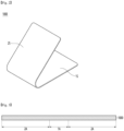
- FIG. 1 is a perspective view of the display device according to the embodiment.
- FIGS. 2 to 4 are perspective and cross-sectional views of the elastic member of the display device according to the embodiment.
- a display device 10 may include an elastic member 1000 and a panel including a display panel 2000 and a touch panel 3000 disposed on the elastic member 1000.
- the elastic member 1000 may support the display panel 2000 and the touch panel 3000. That is, the elastic member 1000 may be a support substrate supporting the display panel 2000 and the touch panel 3000.
- the touch panel 3000 may be integrally formed with the display panel 2000.
- the touch panel 3000 may be integrally formed with the display panel 2000 in an on-cell or in-cell method.
- the elastic member 1000 may include a metallic material and a non-metallic material.
- the elastic member 1000 may be formed of a plurality of layers, and the plurality of layers may include at least one of the metallic material and the non-metallic material.
- the elastic member 1000 may include metal, metal alloy, plastic, a composite material (e.g., carbon fiber reinforced plastic, a magnetic or conductive material, a glass fiber reinforced material, etc.), ceramic, sapphire, glass, and the like.
- the elastic member 1000 may be flexible or foldable. That is, the elastic member 1000 may be folded or bent in one direction. That is, the elastic member 1000 may be a substrate for display applied to a flexible display device or a foldable display device.
- a first direction 1D and a second direction 2D that is different from the first direction 1D may be defined.
- the first direction 1D may be defined as the same direction as a folding axis direction of the elastic member 1000.
- the second direction may be a direction perpendicular to the first direction.
- One direction of the first direction 1D and the second direction 2D may be defined as a width direction of the elastic member 1000, and the other direction may be defined as a longitudinal direction of the elastic member 1000.
- the elastic member 1000 may be folded with any one of the width direction and the longitudinal direction of the elastic member 1000 as a folding axis.
- the first direction is defined as the same direction as the folding axis.
- the first direction is defined as the width direction of the elastic member 1000
- the second direction is defined as the longitudinal direction of the elastic member 1000.
- the elastic member 1000 may include at least two regions.
- the elastic member 1000 may include a first region 1A and a second region 2A.
- the first region 1A may be defined as a region where the elastic member 1000 is folded. That is, the first region 1A may be defined as a region where the elastic member 1000 and the display device 10 including the elastic member 1000 are folded. That is, the first region 1A may be a folding region.
- the second region 2A may be defined as a region where the elastic member 1000 is not folded. That is, the second region 2A may be defined as a region where the elastic member 1000 and the display device 10 including the elastic member 1000 are not folded. That is, the second region 2A may be an unfolding region.
- the first region 1A and the second region 2A will be described in detail below.
- the display panel 2000 may be disposed on the elastic member 1000.
- the display panel 2000 may include a plurality of pixels including a switching thin film transistor, a driving thin film transistor, a power storage device, and an organic light-emitting diode (OLED).
- OLED organic light-emitting diode
- the pixel refers to a minimum unit for displaying an image, and the display panel displays an image through the plurality of pixels.
- the display panel may include a substrate, a gate line disposed on the substrate, a data line isolated from the gate line, and a common power line.
- one pixel may be defined by the gate line, the data line, and the common power line as a boundary.
- the substrate may include a material having flexible properties such as a plastic film, and the display panel 2000 may be implemented by disposing an organic light-emitting diode and a pixel circuit on a flexible film.
- the touch panel 3000 may be disposed above the display panel 2000.
- the touch panel 3000 may implement a touch function in the foldable display device or the flexible display device, and the touch panel may be omitted in a foldable display device or a flexible display device that simply displays an image without the touch function.
- the touch panel 3000 may include a substrate and a touch electrode disposed on the substrate.
- the touch electrode may sense a position of an input device touched by the foldable display device or the flexible display device by a capacitive type or a resistive type.
- the substrate of the touch panel 3000 may include a material having flexible properties such as a plastic film, and the touch panel 3000 may be implemented by disposing the touch electrode on the flexible film.
- the substrate of the touch panel 3000 may be a substrate of the display panel or a part of the display panel.
- the touch panel 3000 and the display panel 2000 can be integrally formed, and a thickness of the display device may be reduced.
- the elastic member 1000 and the display panel 2000 may have different sizes.
- an area of the elastic member 1000 may be 90% or more to 110% or less of an area of the display panel 2000.
- the area of the elastic member 1000 may be 95% or more to 105% or less of the area of the display panel 2000.
- the area of the elastic member 1000 may be 97% or more to 100% or less of the area of the display panel 2000.
- the area of the elastic member 1000 is 90% or less of the area of the display panel 2000, support force of the elastic member 1000 supporting the display panel 2000 or the touch panel 3000 is deteriorated, and thus a curl phenomenon or the like may occur in the unfolding region of the elastic member 1000. Accordingly, when a user visually recognizes a screen region, visibility may be deteriorated, and when a touch is driven, a screen of a touch region may be incomplete due to a curled region, and thus a touch malfunction may occur.
- the support force for supporting the display panel or the touch panel may be secured by the elastic member 1000, but a bezel region of a display device including the substrate, the display panel, and the touch panel may increase. Accordingly, it is impossible to provide a wide effective screen region to the user, which may cause inconvenience in using the display device.
- a cover window protecting the foldable display device or the flexible display device may be additionally disposed above the touch panel 3000 or above the display panel 2000 (when the touch panel is omitted).
- the elastic member 1000, the display panel 2000, and the touch panel 3000 may be adhered to each other through an adhesive layer or the like.
- the display device includes the elastic member 1000.
- the elastic member 1000 may be bent in one direction.
- the elastic member 1000 may include a first surface 1S and a second surface 2S opposite to the first surface 1S.
- the first surface 1S or the second surface 2S may be bent to face each other. That is, the elastic member 1000 may be bent so that the surfaces on which the panels are disposed face each other. Alternatively, the elastic member 1000 may be bent so that a surface opposite to the surface on which the panels are disposed faces.
- the embodiment is not limited thereto, and the second surface and the first surface of the elastic member 1000 may be bent to alternately face each other. That is, the elastic member 1000 may include a plurality of first regions and a plurality of second regions.
- the elastic member 1000 is bent in a direction in which the first surfaces 1S face each other.
- the elastic member 1000 may have the first region 1A and the second region 2A defined therein.
- the first region 1A and the second region 2A may be regions defined when the elastic member 1000 is bent in the direction in which the first surfaces 1S face each other.
- the elastic member 1000 is bent in one direction, and the elastic member 1000 may be divided into the first region 1A that is folded (folding region) and the second region 2A that is not folded (unfolding region).
- the elastic member 1000 may include a first region 1A that is a region where the elastic member 1000 is bent.
- the elastic member 1000 may include a second region 2A that is not bent and is disposed adjacent to the first region 1A.
- the second region 2A may be formed on the left and right sides of the first region 1A, respectively, based on a bending direction of the elastic member 1000. That is, the second region 2A may be disposed at both ends of the first region 1A. That is, the first region 1A may be disposed between the second regions 2A.
- the embodiment is not limited thereto, and the first region 1A may be further formed outside the second region 2A.
- the first region 1A and the second region 2A may be formed on the same elastic member 1000. That is, the first region 1A and the second region 2A may be formed integrally with each other without being separated from the same one elastic member 1000.
- Sizes of the first region 1A and the second region 2A may be different from each other.
- the size of the second region 2A may be greater than the size of the first region 1A.
- an area of the first region 1A of the elastic member 1000 may be 1% or more to 30% or less of an entire area of the elastic member 1000.
- the area of the first region 1A of the elastic member 1000 may be 5% or more to 20% or less of the entire area of the elastic member 1000.
- the area of the first region 1A of the elastic member 1000 may be 10% or more to 15% or less of the entire area of the elastic member 1000.
- the area of the first region 1A of the elastic member 1000 exceeds 30% of the entire area of the elastic member 1000, curl may occur in the folding region of the display panel 2000 when the substrate is folded. Accordingly, when the user visually recognizes the screen region, the visibility may be deteriorated, and when the touch is driven, the screen of the touch region may be incomplete due to the curled region, and thus the touch malfunction may occur.
- the first region 1A is positioned in a central portion of the elastic member 1000, but the embodiment is not limited thereto. That is, the first region 1A may be positioned in one end and an end region of the elastic member 1000. That is, the first region 1A may be positioned at one end and the end region of the elastic member 1000 such that the size of the first region 1A is asymmetric.
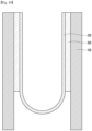
- FIG. 4 is a side view of the substrate for display after the substrate is folded.
- the elastic member 1000 may be folded in one direction based on the folding axis.
- the first surfaces may be folded in a direction facing each other.
- the first region 1A and the second region 2A may be formed on the elastic member 1000. That is, a folding region formed as the elastic member 1000 is folded in one direction and an unfolding region positioned at both ends of the folding region may be formed on the elastic member 1000.
- the folding region may be defined as a region where a curvature R is formed, and the unfolding region may be defined as a region where the curvature R is not formed or the curvature is close to zero.
- the elastic member 1000 may be folded in one direction to be formed in an order of the unfolding region, the folding region, and the unfolding region.
- a plurality of pattern parts may be formed in at least one of the first region 1A and the second region 2A in order to reduce and distribute stress generated when the elastic member 1000 is folded.
- the pattern parts will be described in detail below.
- FIG. 4 illustrates that the first surfaces 1S of the elastic member 1000 are folded to face each other, but the embodiment is not limited thereto, and the second surfaces 2S may be folded to face each other.
- FIG. 4 illustrates that the curvature is decreased (a radius of the curvature is increased) while the elastic member 1000 extends from a center of the folding axis, but the embodiment is not limited thereto.
- the curvature may decrease or increase while the elastic member 1000 extends from the center of the folding axis. That is, the curvature may decrease and then increase while the elastic member 1000 extends from the center of the folding axis.
- the elastic member 1000 may be formed in a shape in which the curvature decreases and then increases, or the curvature decreases and then increases, and then decreases again while extending from the center of the folding axis. That is, a folding shape of the elastic member 1000 may be formed in various folding shapes as well as a U-shaped shape.
- the elastic member 1000 may be formed of a plurality of layers to realize strength and folding characteristics of the elastic member.
- the elastic member 1000 may be formed by stacking a plurality of layers having different characteristics such as yield strength, elongation, and compressibility.
- an elastic member capable of preventing an increase in flatness in a folding area when the elastic member is folded and restored by controlling characteristics of layers constituting the elastic member will be described.
- the elastic member 1000 may include a first layer 100, a second layer 200 and a third layer 300.
- the elastic member 1000 may include the first layer 100, the second layer 200 on the first layer 100, and the third layer 300 between the first layer 100 and the second layer 200.
- the first layer 100 may include metal.
- the first layer 100 may include a metal and a metal alloy.
- the first layer may include stainless (SUS) or copper (Cu).
- the first layer 100 may be formed of an alloy including at least one of nickel (Ni), chromium (Cr), iron (Fe), titanium (Ti), manganese (Mn), molybdenum (Mo), silver (Ag), zinc (Zn), nitrogen (N), and aluminum (Al) together with copper (Cu).
- a plurality of pattern parts may be disposed on the first layer 100.
- the pattern parts may be disposed on an area corresponding to at least one of the first region 1A and the second region 2A of the elastic member.
- the pattern parts may serve to reduce stress generated by folding when the first layer 100 including metal is folded.
- the pattern parts may be disposed in a shape of a hole formed through the entirety of the first layer 100 or a shape formed through a groove partially through the first layer 100.
- the second layer 200 may be disposed on the first layer 100.
- the second layer 200 may be disposed on the first layer 100 to planarize the surface of the first layer 100.
- the first layer 100 is formed with a plurality of pattern parts having the hole or the groove shape, and the surface of the first layer 100 may not be flat due to the pattern parts. Accordingly, when a panel or the like is directly attached to the first layer 100, the adhesive force with the panel may decrease due to the surface characteristics of the first layer 100.
- the adhesive surface of the elastic member 1000 bonded to the panel may be flattened. That is, the second layer 200 may be defined as a planarization layer of the elastic member 1000.
- the second layer 200 may include metal or non-metal.
- the second layer 200 may include metal or plastic.
- the second layer 200 may include other materials according to characteristics to be implemented among the folding characteristics and strength of the elastic member 1000.
- the second layer 200 may include plastic.
- the second layer 200 may include a material having high elasticity and strength.
- the second layer 200 may include a material including fibers.
- the second layer 200 will be described in detail below.
- the third layer 300 may be disposed between the first layer 100 and the second layer 200.
- the third layer 300 may be disposed between the first layer 100 and the second layer 200 to adhere the first layer 100 and the second layer 200. That is, the third layer 300 may serve as an adhesive layer in the elastic member 1000.
- the third layer 300 may include pressure sensitive adhesive (PSA), but the embodiment is not limited thereto.
- PSA pressure sensitive adhesive
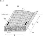
- FIGS. 6 to 8 are perspective and cross-sectional views of the second layer 200.
- FIG. 6 is a perspective view of a portion of the second layer 200.
- Figs. 7 and 8 are cross-sectional views taken along area A-A' of FIG. 6 .
- the second layer 200 may include a base material 210 and a plurality of fibers 220 disposed inside the base material 210.
- the base material 210 may support the fibers 220 disposed inside the second layer 200.
- the base material 210 may be formed in a structure in which the fibers 220 are impregnated into the base material 210.
- the base material 210 may include a resin material.
- the base material 210 may be include at least one resin material selected from polyimide, polysulfone, polyphenylene sulfide, polyamide-imide, polyether ether ketone, Liquid-Crystal Polyester, Polyamide, Polyoxymethylene, Polycarbonate, Polybutylene terephthalate, modified polyphenyleneoxide, epoxy and acrylate.
- the fiber 220 may have a set length and diameter.
- the diameter of the fiber 220 may be 0.0001 mm to 0.01 mm.
- the length of the fiber 220 may vary according to the size of the second layer 200.
- the fiber 220 may be disposed inside the base material 210. That is, the fiber 220 may be impregnated into the resin material of the base material 210.
- the fiber 220 may include a material having high elasticity.
- the fiber 220 may include at least one of carbon fiber, glass fiber, and ceramic fiber.
- the second layer 200 may include a 1a region 1Aa corresponding to the first region 1A of the elastic member 1000 and a 2a region 2Aa corresponding to the second area 2A of the elastic member 1000.
- the fiber 220 may be disposed in at least one of the 1a region 1Aa and the 2a region 1Aa of the second layer 200.
- the fibers 220 may be disposed in both the 1a region 1Aa and the 2a region 2Aa of the second layer 200. Accordingly, in the second layer 200, characteristics of the 1a region 1Aa that is the folding area and the 2a region 2Aa that is the unfolding area may be similar. Accordingly, it is possible to prevent deformation of the second layer 200 from occurring during the process of forming the second layer 200 due to differences in characteristics.
- the fiber 220 may be disposed in any one of the 1a region 1Aa and the 2a region 2Aa of the second layer 200.
- the fibers 220 may be disposed only in the 1a region 1Aa, which is a folding region of the second layer 200, or only in the 2a region 2Aa, which is an unfolding region of the second layer 200.
- the fibers 220 may be disposed in both the 1a region 1Aa and the 2a region 2Aa of the second layer 200. Also, more fibers 220 may be disposed in the 1a region 1Aa.
- a region where the fiber 220 and the 1a region 1Aa overlap may be larger than a region where the fiber 220 and the 2a region 2Aa overlap.
- the region where the fiber 220 and the 1a region 1Aa overlap may be smaller than the region where the fiber 220 and the 2a region 2Aa overlap.
- a volume % of the fiber 220 with respect to the total area of the 2a region 2Aa may be smaller than a volume % of the fiber 220 with respect to the total area of the 1a region 1Aa.
- sufficient strength and elasticity may be secured in the folding region of the second layer 200 by disposing the fibers 220 in a larger amount in the folding area of the second layer 200. Accordingly, reduction in flatness due to deformation of the second layer 200 during folding may be prevented.
- a characteristic difference between the 1a region 1Aa that is the folding region and 2a region 2Aa that is the unfolding region may be reduced. Accordingly, it is possible to prevent deformation of the second layer 200 from occurring during the process of forming the second layer 200 due to differences in characteristics.
- the second layer 200 may have a thickness within a set range.
- the thickness of the second layer 200 may be defined as the thickness of the base material 210.
- the thickness T of the second layer 200 may be 15 ⁇ m or more.
- the thickness T of the second layer 200 may be 15 ⁇ m to 200 ⁇ m.
- the thickness T of the second layer 200 may be 30 ⁇ m to 100 ⁇ m.
- the thickness T of the second layer 200 is less than 15 ⁇ m, it is difficult to arrange fibers inside the second layer 200, and thus process efficiency may decrease.
- the thickness T of the second layer 200 exceeds 200 ⁇ m, the overall thickness of the display device including the elastic member may increase, and folding reliability of the elastic member may decrease.
- the folding direction of the second layer 200 and the elastic member 1000 may be defined by the length direction of the fibers 220 of the second layer 200.
- the folding axis of the second layer 200 and the elastic member 1000 may be different from the longitudinal direction of the second layer 200.
- the folding axes of the second layer 200 and the elastic member 1000 may be defined in a direction perpendicular to the longitudinal direction of the second layer 200.
- the folding axis of the elastic member 1000 may be defined in a direction perpendicular to or close to the average in the longitudinal direction of the fibers 220.
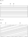
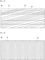
- FIGS. 10 to 13 are views for explaining various arrangements of the fibers 220 of the second layer 200.
- the fibers 220 may be disposed in various directions inside the base material 210.
- the fibers 220 may be disposed while extending in one direction in the longitudinal direction of the second layer 200.
- the fiber 220 may be tilted at a predetermined angle with the longitudinal direction of the second layer 200 and extended in one direction.
- the fibers 220 may be disposed while extending in multiple directions.
- the fibers 220 may include fibers extending in one direction in the length direction of the second layer 200 and fibers tilting and extending at a predetermined angle with the length direction of the second layer 200.
- the fibers may include curves and may be disposed while extending in one direction or in multiple directions in the longitudinal direction of the second layer 200.
- the second layer 200 may include an alignment mark 250 for checking the folding direction.
- an alignment mark 250 capable of defining and confirming the length direction of the fibers 220 may be formed on at least one of one surface and the other surface of the second layer 200 .
- the alignment mark 250 may be disposed on the 2a region 2Aa of the second layer 200. Since the alignment mark 250 is disposed on the 2a area 2Aa of the second layer 200, which is an unfolding area other than a folding area, damage or deformation of the alignment mark 250 may be prevented during folding. In addition, it is possible to prevent the folding reliability from being reduced by the alignment mark.
- the alignment mark 250 may be formed by etching the surface of the second layer 200. Alternatively, the alignment mark 250 may be formed on the second layer 200 by a printing process.
- the first layer 100 may be formed in multiple layers.
- the first layer 100 may include a 1-1 layer 110 and a 1-2 layer 120 on the 1-1 layer 110 .
- the 1-1 layer 110 and the 1-2 layer 120 may include a metal material.
- the 1-1 layer 110 and the 1-2 layer 120 may include different metal materials.
- the 1-1 layer 110 and the 1-2 layer 120 may include materials having different thermal conductivity.
- the 1-1 layer 110 may include a material having higher thermal conductivity than the 1-2 layer 120.
- the 1-1 layer 110 and the 1-2 layer 120 may include materials having different yield strengths.
- the 1-2 layer 120 may include a material having higher yield strength than the 1-1 layer 110.
- the 1-1 layer 110 may include copper or a copper alloy
- the 1-2 layer 120 may include stainless (SUS), but the embodiment is not limited thereto.
- the 1-1 layer 110 and the 1-2 layer 120 may include various materials that satisfy the thermal conductivity and the yield strength.
- the 1-1 layer 110 and the 1-2 layer 120 may be disposed in direct contact with each other.
- the 1-1 layer 110 and the 1-2 layer 120 may be manufactured in a clad method.
- a clad bonding is a method of bonding the 1-1 layer 110 and the 1-2 layer 120 by welding, rolling, casting, extrusion, or the like without bonding using an adhesive.
- the clad bonding destroys the mutual tissue of each layer and stabilizes the bonding of each layer by penetration between tissues, so that the bonding strength may be more excellent over time.
- bonding may be formed by inducing atomic diffusion between heterogeneous materials at the interface of different layers by rolling. Unlike adhesion using an adhesive, the clad bonding may be processed into a curved surface. In addition, since the clad bonding uses atomic diffusion bonding, it may maintain a bonding state for a longer time than adhesion using an adhesive.
- the 1-1 layer 110 and the 1-2 layer 120 may have the same or different thicknesses.
- the thickness of the 1-1 layer 110 may be greater than that of the 1-2 layer 120.
- the thickness of the 1-2 layer 120 may be greater than that of the 1-1 layer 110.
- the thickness of the 1-1 layer 110 and the thickness of the 1-2 layer 120 may vary depending on characteristics to be implemented in the elastic member 1000.
- the first layer 100 may include a 1-1 layer 110, a 1-2 layer 120 on the 1-1 layer 110, and a 1-3 layer 130 the 1-2 layer 120.
- the 1-1 layer 110, the 1-2 layer 120, and the 1-3 layer 130 may include a metal material.
- the 1-1 layer 110, the 1-2 layer 120, and the 1-3 layer 130 may include the same or different metal materials.
- the 1-1 layer 110 and 1-3 layer 130 may include the same material, and the 1-2 layer 120 may include a material different from the 1-1 layer 110 and the 1-3 layer 130.
- the 1-1 layer 110 and the 1-3 layer 130 may include a material having different thermal conductivity from the 1-2 layer 120.
- the 1-1 layer 110 and the 1-3 layer 130 may include a material having a greater thermal conductivity than the 1-2 layer 120.
- the 1-1 layer 110 and the 1-3 layer 130 may include materials with different yield strengths from the 1-2 layer 120.
- the 1-2 layer 120 may include a material having a greater yield strength than the 1-1 layer 110 and the 1-3 layer 130.
- the 1-1 layer 110 and the 1-3 layer 130 may include copper or a copper alloy, and the 1-2 layer 120 may include (SUS), but the embodiment is not limited thereto.
- the 1-1 layer 110, the 1-2 layer 120 and the 1-3 layer 130 may include various materials that satisfy the thermal conductivity and the yield strength.
- the 1-1 layer 110, the 1-2 layer 120, and the 1-3 layer 130 may be disposed in direct contact with each other.
- the 1-1 layer 110, the 1-2 layer 120, and the 1-3 layer 130 may be manufactured by the clad method described above.
- the 1-1 layer 110, the 1-2 layer 120, and the 1-3 layer 130 may be disposed to have the same or different thicknesses.
- the thickness of the 1-1 layer 110 and the 1-3 layer 130 may be greater than that of the 1-2 layer 120.
- the thickness of the 1-2 layer 120 may be greater than that of the 1-1 layer 110 and the 1-3 layer 130.
- the thickness of the 1-1 layer 110, the thickness of the 1-2 layer 120 and the thickness of the 1-3 layer 130 may vary depending on characteristics to be implemented in the elastic member 1000.
- the first layer of the elastic member may include at least one of the 1-1 layer, the 1-2 layer, and the 1-3 layer.
- the elastic member according to the first embodiment may include the second layer including the fiber.
- the second layer may be disposed on the first layer to planarize the elastic member.
- the second layer includes a plastic material
- the tensile strength and yield strength may be smaller than those of the first layer. Accordingly, plastic deformation may occur in the folding region of the second layer in the process of folding the elastic member. Therefore, when the elastic member is repeatedly folded, repeated plastic deformation occurs, which may reduce the flatness of the folding area of the second layer.
- the elastic member according to the first embodiment may improve tensile strength and yield strength of the second layer forming the elastic member.
- the overall tensile strength and yield strength of the second layer may be increased.
- FIGS. 16 and 17 a layer structure of the elastic member according to a second embodiment will be described with reference to FIGS. 16 and 17 .
- a description similar to the elastic member according to the first embodiment described above will be omitted.
- the same drawing code is assigned to the same configuration as the elastic member according to the first embodiment described above.
- the elastic member 1000 may include a second layer 200.
- the elastic member 1000 may include a 2-1 layer 201 and a 2-2 layer 202 disposed on the 2-1 layer 201. That is, the elastic member according to the second embodiment may include the 2-1 layer 201 corresponding to the first layer described above and the 2-2 layer 202 corresponding to the second layer described above.
- the 2-1 layer 201 may include a first base material 211 and a first fiber 221.
- the 2-2 layer 202 may include a second base material 212 and a second fiber 222.
- the 2-1 layer 201 and the 2-2 layer 202 may have the same thickness. Alternatively, the 2-1 layer 201 and the 2-2 layer 202 may have different thicknesses.
- the first base material 211 and the second base material 212 may directly or indirectly contact each other.
- the first base material 211 and the second base material 212 may be disposed in direct contact with each other.
- an adhesive layer 203 is disposed between the first base material 211 and the second base material 212, and the first base material 211 and the second base material 212 may be bonded by the adhesive layer 203.
- the first base material 211 and the second base material 212 may include the same or different materials.
- the first fiber 221 and the second fiber 222 may include the same or different materials.
- the inner and outer surfaces of the elastic member may be defined.
- Compressive stress may be generated on the folding inner surface of the elastic member, and tensile stress may be generated on the outer surface of the elastic member.
- the elastic member may have different properties on one surface and the other surface.
- the base material and fiber of the 2-1 layer 201 may include materials that can prevent plastic deformation due to tensile stress
- the base material and fiber of the 2-2 layer 202 may include materials that can prevent plastic deformation due to compressive stress.
- the elastic member according to the second embodiment may improve the folding reliability of the elastic member by changing the characteristics of the layers according to the stress and stress generated on each surface of the elastic member.
- FIGS. 18 and 19 a layer structure of the elastic member according to a third embodiment will be described with reference to FIGS. 18 and 19 .
- a description similar to the elastic member according to the first embodiment described above will be omitted.
- the same drawing code is assigned to the same configuration as the elastic member according to the first embodiment described above.
- the elastic member 1000 may include a first layer 100, a second layer 200 and a third layer 300.
- the elastic member according to the third embodiment may have the same layer structure as the elastic member according to the first embodiment described above.
- the elastic member according to the third embodiment may have voids in the first layer 100 and the third layer 300, respectively.
- the first layer 100 may include a first void A1
- the third layer 300 may include a second void A2.
- the first void A1 and the second void A2 may be disposed in the first region 1A that is a folding region of the elastic member 1000.
- the first layer 100 may be separated into two first layers by the first void A1, and the third layer 300 may be separated into two third layers by the second void A2.
- the first void A1 and the second void A2 may have different widths.
- a width of the first void A1 may be smaller than a width of the second void A2.
- the width of the first void A1 may be reduced.
- the folding region of the elastic member 1000 may be formed only in the second layer 200 by the first void A1 and the second void A2. That is, the first layer 100 only serves to support the second layer 200, and may not be folded when the elastic member 1000 is folded
- the first layer 100 and the third layer 300 may only increase the widths of the first void A1 and the second void A2, and may not be folded, and only the second layer 200 may be folded forming a folding region.
- the curvature of the elastic member may be increased, that is, the radius of curvature may be reduced.
- yield strength and tensile strength of the second layer 200 are improved, plastic deformation of the second layer 200 is prevented, thereby improving folding reliability of the elastic member. That is, the elastic member according to the third embodiment may have improved folding reliability while increasing a folded curvature.
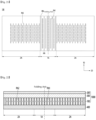
- FIGS. 20 and 21 are top views of the first layer 100 of the elastic member.
- the first layer 100 of the elastic member may include a first region 1A that is the folding area and a second region 2A that is the unfolding area.
- the first region 1A and the second region 2A may have different widths.
- the width of the first region 1A may be smaller than that of the second region 2A.
- the first layer 100 may include a plurality of pattern parts PA.
- the first layer 100 may include a first pattern part PA1 disposed in the first region 1A.
- the first pattern part PA1 may reduce compressive stress and tensile stress generated when the first layer 100 is folding and restoration.
- the first pattern part PA1 may be formed in a hole or groove shape.
- the first pattern part PA may be formed in a hole shape penetrating one surface of the first layer 100 and the other surface opposite to the one surface.
- the first pattern part PA1 may be formed in a groove shape formed on one surface or the other surface.
- the first pattern part PA1 disposed in the first region 1A which is a region where the first layer 100 is folded, may easily fold the elastic member 1000 including the first layer 100.
- the thickness of the elastic member 1000 is reduced in a region where the elastic member 1000 is folded by the first pattern part PA1. Accordingly, since the compressive stress is reduced, the elastic member 1000 may be easily folded.
- the first layer 100 may further include a second pattern part PA2.
- the first layer 100 may further include the second pattern part PA2 disposed in the second region 2A.
- the second pattern part PA2 may be formed in a hole or groove shape.
- the second pattern part PA2 may be formed in a hole shape penetrating one surface and the other surface of the first layer 100.
- the second pattern part PA2 may be formed in a groove shape formed on one surface or the other surface of the first layer 100.
- the second pattern part PA2 disposed in the second region 2A which is a region where the first layer 100 is not folded, may similarly maintain physical characteristics of the first region 1A and the second region 2A.
- a deformation difference due to heat between the first region 1A and the second region 2A where the first pattern part PA1 is disposed may be reduced by the second pattern part PA2. That is, since pattern parts are formed in both the first region 1A and the second region 2A, when heat is applied to the first layer 100, the difference in deformation due to heat between the first region 1A and the second region 2A may be reduced. Accordingly, it is possible to prevent the first layer 100 from being bent or distorted due to the deformation difference between the first region 1A and the second region 2A.
- the stress unevenness of the first region 1A and the second region 2A may be reduced by the second pattern part PA2 formed in the second region 2A to prevent bending of the elastic member.
- the second pattern part PA2 may be formed in the same or similar shape as the first pattern part PA1.
- the second pattern part PA2 is formed in a shape having a long direction and a short direction.
- the long direction of the second pattern part PA2 and the long direction of the first pattern part PA1 extend in the same or similar direction to each other.
- the short direction of the second pattern part PA2 and the short direction of the first pattern part PA1 may extend in the same or similar direction.
- the first layer 100 may include a hinge part HN.
- a plurality of hinge parts HN may be disposed in the first region 1A of the first layer 100.
- the hinge part HN is a region opened at an end region of the first layer 100 for folding of the first layer 100, and may be formed only in the first region 1A. Accordingly, the hinge part HN is a point at which folding of the first layer 100 starts, and the first region 1A and the second region 2A of the first layer 100 may be divided depending on whether the hinge part is formed or not.
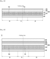
- the folding support may include the elastic member and a protective layer 400.
- FIG. 22 is a view showing a folding support in which the third layer is not disposed inside the pattern part of the first layer.
- FIG. 23 is a view showing a folding support in which the third layer is formed of a plurality of layers and the third layer is disposed inside the pattern part of the first layer.
- the folding support may include the aforementioned elastic member 1000 and the protective layer 400 disposed under the elastic member 1000.
- the protective layer 400 may be disposed under the first layer 100 or the 1-1 layer 110 of the elastic member 1000.
- an adhesive layer is disposed between the protective layer 400 and the first layer 100 or between the protective layer 400 and the 1-1 layer 110, and the elastic member 1000 and the protective layer 400 may be bonded by the adhesive layer.
- the protective layer 400 may have a color.
- the protective layer 400 may be formed in a black-based color.
- the protective layer 400 may include metal particles.
- the protective layer 400 may include copper particles. Accordingly, since the thermal conductivity of the protective layer 400 is improved, heat generated in the display device may be released by the protective layer 400 .
- the protective layer 400 may be disposed on one region of the elastic member 1000.
- the protective layer 400 may be disposed in a region corresponding to the first region 1A of the elastic member 1000.
- the protective layer 400 may be disposed in regions corresponding to the first region 1A and the second region 2A of the elastic member 1000.
- the protective layer 400 may be disposed in a region corresponding to the first region 1A and the second region 2A of the elastic member 1000, and may be disposed in an area smaller than the combined area of the first region 1A and the second region a 2A.
- the protective layer 400 may be disposed in an area of 80% to 90% of the sum of the area of the first region 1A and the area of the second region 2A of the elastic member.
- the thickness of the protective layer 400 may be smaller than the total thickness of the elastic member 1000. That is, the thickness of the protective layer 400 may be smaller than the sum of the thicknesses of the first layer, the second layer, and the third layer of the elastic member 400.
- FIGS. 24 to 26 a display device including a folding support according to the above-described embodiment will be described with reference to FIGS. 24 to 26 .
- the display device 10 may include the folding support and a panel.
- FIG. 20 is a view showing the display device in which the third layer of the elastic member is not disposed inside the pattern part of the first layer.
- FIG. 21 is a view showing the display device in which a third layer of the elastic member is formed of a plurality of layers and the third layer is disposed inside the pattern part of the first layer.
- the pattern parts PA1 and PA2 formed on the first layer 100 may be formed in various shapes as shown in FIGS. 24 and 25 .
- the display device 10 may include the folding support and a panel layer 600 disposed on the folding support and including a display panel and/or a touch panel.
- the folding support may include the elastic member 1000 including the first layer 100, the second layer 200, and the third layer 300, and a protective layer 400 disposed under the elastic member 1000.
- the protective layer 400 may be disposed under the first layer 100 or the 1-1 layer 110 of the elastic member 1000.
- An adhesive layer 500 is disposed between the elastic member 1000 and the panel layer 600, and the elastic member 1000 and the panel layer 600 may be bonded by the adhesive layer 500.
- an adhesive surface of the elastic member 1000 may be flattened by the second layer 200, the elastic member and the panel layer may be stably bonded without a step.
- the adhesive layer 500 between the elastic member 1000 and the panel layer 600 may have characteristics different from those of the third layer 300 of the elastic member 1000.
- the adhesive layer 500 may have a smaller thickness than the third layer 300.
- the adhesive layer 500 may have a thickness of 5 ⁇ m to 15 ⁇ m.
- the adhesive layer 500 may have lower adhesive properties than the third layer 300.
- the adhesive strength of the adhesive layer 500 may be 400 or less.
- the adhesive layer 500 and the third layer 300 may have different elastic modulus. That is, the adhesive layer 500 does not have the same storage modulus, creep recovery, and tangent delta values as the third layer. Accordingly, the adhesive layer 500 may not have elastic properties other than adhesive properties.
- FIG. 27 is a view for explaining an example in which an elastic member according to embodiments is applied.
- the elastic member according to the embodiments may be applied to a flexible or foldable display device for displaying a display.
- the elastic member according to the embodiments may be applied to a flexible display device such as a mobile phone or a tablet.
- Such an elastic member may be applied to a flexible display device such as a mobile phone or a tablet that is flexible, bent, or folded.
- the elastic member is applied to the flexible display device such as the mobile phone or the tablet that is flexible, bent or folded and improves the folding reliability in a display device that is repeatedly folded or folded, thereby improving the reliability of the flexible display device.
Landscapes
- Engineering & Computer Science (AREA)
- Chemical & Material Sciences (AREA)
- Theoretical Computer Science (AREA)
- Physics & Mathematics (AREA)
- General Physics & Mathematics (AREA)
- General Engineering & Computer Science (AREA)
- Ceramic Engineering (AREA)
- Materials Engineering (AREA)
- Human Computer Interaction (AREA)
- Manufacturing & Machinery (AREA)
- Health & Medical Sciences (AREA)
- Chemical Kinetics & Catalysis (AREA)
- Medicinal Chemistry (AREA)
- Polymers & Plastics (AREA)
- Organic Chemistry (AREA)
- Optics & Photonics (AREA)
- Mechanical Engineering (AREA)
- Laminated Bodies (AREA)
- Devices For Indicating Variable Information By Combining Individual Elements (AREA)
- Electroluminescent Light Sources (AREA)
Abstract
Description
- An embodiment relates to an elastic member and display device having the same.
- Recently, there is an increasing demand for a flexible or foldable display device capable of easily carrying various applications and displaying an image on a large screen when being carried.
- Such a flexible or foldable display device is folded or partially bent when being carried or stored, and may be implemented with the display unfolded when displaying images. Accordingly, an image display region may be increased, and a user may easily carry the display.
- After the flexible or foldable display device is folded or bent, a restoration process of unfolding the flexible display device again may be repeated.
- That is, since the flexible or foldable display device repeats folding and unfolding operations, a substrate of the flexible display device is repeatedly used, so that flatness may be deteriorated.
- In detail, in the flexible or foldable display device, since a folding region is a region where stress is concentrated during repeated folding and unfolding, the flatness may be deteriorated compared with unfolding region.
- Accordingly, there is a problem that cracks occur in the folding region or wrinkles visually recognized from the outside occur, and thus the lifespan of the flexible or foldable display device is reduced and the reliability is deteriorated.
- Therefore, there is a need for an elastic member having a new structure capable of solving the above problems
- Embodiments provide an elastic member capable of improved flatness even in repetitive folding and restoration processes, and a display device including the same.
- An elastic member according to an embodiment includes: a first region and a second region, wherein a first direction is defined as a width direction of the elastic member and a second direction defined as a longitudinal direction of the elastic member, wherein the first region is defined as a folding region that is folded with the first direction as a folding axis, and the second region is defined as an unfolding region, wherein the elastic member includes a first layer and a second layer on the first layer; wherein the second layer includes a base material and fibers disposed inside the base material, wherein the fibers are disposed while extending in the second direction.
- The elastic member according to an embodiment may improve tensile strength and yield strength of the second layer forming the elastic member. In detail, since the fibers are disposed inside the second layer, the overall tensile strength and yield strength of the second layer may be increased.
- Accordingly, even if the elastic member is repeatedly folded, plastic deformation of the second layer of the elastic member may be prevented. Thereby, folding reliability and flatness of the elastic member are improved.
- In addition, the elastic member according to the embodiment may have improved folding reliability by changing the characteristics of the layers according to the stress generated on each surface of the elastic member and the size of the stress.
- Also, in the elastic member according to the embodiment, since only the second layer including plastic is folded, the curvature of the elastic member may increase. That is, the radius of curvature of the elastic member may be reduced. In addition, since the yield strength and tensile strength of the second layer are improved, the plastic deformation of the second layer is prevented. Thus, the folding reliability of the elastic member may be improved. That is, the elastic member according to the embodiment may have improved folding reliability while increasing the curvature.
-
-
FIG. 1 is a perspective view of a display device according to the embodiment. -
FIG. 2 is a perspective view of an elastic member according to the embodiment. -
FIG. 3 is a side view before folding of the elastic member according to the embodiment. -
FIG. 4 is a side view after folding of the elastic member according to the embodiment. -
FIG. 5 is a cross-sectional view of a layer structure of the elastic member according to a first embodiment. -
FIG. 6 is a perspective view of a second layer of the elastic member according to the first embodiment. -
FIGS .7 to 9 are cross-sectional views taken along area A-A' ofFIG. 6 . -
FIG. are views for explaining the arrangement of fibers of the second layer of the elastic member.S 10 to 13 -
FIGS. 14 and15 are cross-sectional views of another layer structure of the elastic member according to the first embodiment. -
FIGS. 16 and17 are cross-sectional views of the layer structure of the elastic member according to a second embodiment. -
FIG. 18 is a cross-sectional view of the layer structure of the elastic member according to a third embodiment. -
FIG. 19 is a cross-sectional view of a folded elastic member according to the third embodiment. -
FIG. 20 is a top view of the elastic member according to the embodiment. -
FIG. 21 is another top view of the elastic member according to the embodiment. -
FIGS. 12 to 23 are cross-sectional views of a flexible support including the elastic member according to the embodiment. -
FIGS. 24 to 26 are cross-sectional views of a display device including the flexible support according to the embodiment. -
FIG. 27 is a view for explaining an application example of the display device according to the embodiment. - Hereinafter, embodiments of the present disclosure will be described in detail with reference to the accompanying drawings. However, the spirit and scope of the present disclosure is not limited to a part of the embodiments described, and may be implemented in various other forms, and within the spirit and scope of the present disclosure, one or more of the elements of the embodiments may be selectively combined and replaced. In addition, unless expressly otherwise defined and described, the terms used in the embodiments of the present disclosure (including technical and scientific terms) may be construed the same meaning as commonly understood by one of ordinary skill in the art to which the present disclosure belongs, and the terms such as those defined in commonly used dictionaries may be interpreted as having a meaning that is consistent with their meaning in the context of the relevant art.
- In addition, the terms used in the embodiments of the present disclosure are for describing the embodiments and are not intended to limit the present disclosure. In this specification, the singular forms may also include the plural forms unless specifically stated in the phrase, and may include at least one of all combinations that may be combined in A, B, and C when described in "at least one (or more) of A (and), B, and C".
- Further, in describing the elements of the embodiments of the present disclosure, the terms such as first, second, A, B, (a), and (b) may be used. These terms are only used to distinguish the elements from other elements, and the terms are not limited to the essence, order, or order of the elements.
- In addition, when an element is described as being "connected" or "coupled" to another element, it may include not only when the element is directly "connected" or "coupled" to other elements, but also when the element is "connected" or "coupled" by another element between the element and other elements.
- Further, when described as being formed or disposed "on (over)" or "under (below)" of each element, the "on (over)" or "under (below)" may include not only when two elements are directly connected to each other, but also when one or more other elements are formed or disposed between two elements.
- Furthermore, when expressed as "on (over)" or "under (below)", it may include not only the upper direction but also the lower direction based on one element.
- Hereinafter, an elastic member according to an embodiment and a folding support and a display device including the same will be described with reference to the drawings.
-
FIG. 1 is a perspective view of the display device according to the embodiment.FIGS. 2 to 4 are perspective and cross-sectional views of the elastic member of the display device according to the embodiment. - Referring to
FIG. 1 , adisplay device 10 according to the embodiment may include anelastic member 1000 and a panel including adisplay panel 2000 and atouch panel 3000 disposed on theelastic member 1000. - The
elastic member 1000 may support thedisplay panel 2000 and thetouch panel 3000. That is, theelastic member 1000 may be a support substrate supporting thedisplay panel 2000 and thetouch panel 3000. - Meanwhile, the
touch panel 3000 may be integrally formed with thedisplay panel 2000. For example, thetouch panel 3000 may be integrally formed with thedisplay panel 2000 in an on-cell or in-cell method. - The
elastic member 1000 may include a metallic material and a non-metallic material. In detail, theelastic member 1000 may be formed of a plurality of layers, and the plurality of layers may include at least one of the metallic material and the non-metallic material. For example, theelastic member 1000 may include metal, metal alloy, plastic, a composite material (e.g., carbon fiber reinforced plastic, a magnetic or conductive material, a glass fiber reinforced material, etc.), ceramic, sapphire, glass, and the like. - The
elastic member 1000 may be flexible or foldable. That is, theelastic member 1000 may be folded or bent in one direction. That is, theelastic member 1000 may be a substrate for display applied to a flexible display device or a foldable display device. - In the
elastic member 1000, afirst direction 1D and asecond direction 2D that is different from thefirst direction 1D may be defined. For example, thefirst direction 1D may be defined as the same direction as a folding axis direction of theelastic member 1000. In addition, the second direction may be a direction perpendicular to the first direction. - One direction of the
first direction 1D and thesecond direction 2D may be defined as a width direction of theelastic member 1000, and the other direction may be defined as a longitudinal direction of theelastic member 1000. - The
elastic member 1000 may be folded with any one of the width direction and the longitudinal direction of theelastic member 1000 as a folding axis. - Hereinafter, for convenience of description, the first direction is defined as the same direction as the folding axis. In addition, the first direction is defined as the width direction of the
elastic member 1000, and the second direction is defined as the longitudinal direction of theelastic member 1000. - The
elastic member 1000 may include at least two regions. In detail, theelastic member 1000 may include afirst region 1A and asecond region 2A. - The
first region 1A may be defined as a region where theelastic member 1000 is folded. That is, thefirst region 1A may be defined as a region where theelastic member 1000 and thedisplay device 10 including theelastic member 1000 are folded. That is, thefirst region 1A may be a folding region. - In addition, the
second region 2A may be defined as a region where theelastic member 1000 is not folded. That is, thesecond region 2A may be defined as a region where theelastic member 1000 and thedisplay device 10 including theelastic member 1000 are not folded. That is, thesecond region 2A may be an unfolding region. - The
first region 1A and thesecond region 2A will be described in detail below. - The
display panel 2000 may be disposed on theelastic member 1000. - The
display panel 2000 may include a plurality of pixels including a switching thin film transistor, a driving thin film transistor, a power storage device, and an organic light-emitting diode (OLED). In case of the organic light-emitting diode, deposition is possible at a relatively low temperature and may be mainly applied to the flexible display device for reasons of low power and high luminance. Here, the pixel refers to a minimum unit for displaying an image, and the display panel displays an image through the plurality of pixels. - The display panel may include a substrate, a gate line disposed on the substrate, a data line isolated from the gate line, and a common power line. In general, one pixel may be defined by the gate line, the data line, and the common power line as a boundary.
- The substrate may include a material having flexible properties such as a plastic film, and the
display panel 2000 may be implemented by disposing an organic light-emitting diode and a pixel circuit on a flexible film. - The
touch panel 3000 may be disposed above thedisplay panel 2000. Thetouch panel 3000 may implement a touch function in the foldable display device or the flexible display device, and the touch panel may be omitted in a foldable display device or a flexible display device that simply displays an image without the touch function. - The
touch panel 3000 may include a substrate and a touch electrode disposed on the substrate. The touch electrode may sense a position of an input device touched by the foldable display device or the flexible display device by a capacitive type or a resistive type. - The substrate of the
touch panel 3000 may include a material having flexible properties such as a plastic film, and thetouch panel 3000 may be implemented by disposing the touch electrode on the flexible film. - As described above, when the
touch panel 3000 is integrally formed with thedisplay panel 2000, the substrate of thetouch panel 3000 may be a substrate of the display panel or a part of the display panel. Through this, thetouch panel 3000 and thedisplay panel 2000 can be integrally formed, and a thickness of the display device may be reduced. - Meanwhile, the
elastic member 1000 and thedisplay panel 2000 may have different sizes. - For example, an area of the
elastic member 1000 may be 90% or more to 110% or less of an area of thedisplay panel 2000. In detail, the area of theelastic member 1000 may be 95% or more to 105% or less of the area of thedisplay panel 2000. In more detail, the area of theelastic member 1000 may be 97% or more to 100% or less of the area of thedisplay panel 2000. - When the area of the
elastic member 1000 is 90% or less of the area of thedisplay panel 2000, support force of theelastic member 1000 supporting thedisplay panel 2000 or thetouch panel 3000 is deteriorated, and thus a curl phenomenon or the like may occur in the unfolding region of theelastic member 1000. Accordingly, when a user visually recognizes a screen region, visibility may be deteriorated, and when a touch is driven, a screen of a touch region may be incomplete due to a curled region, and thus a touch malfunction may occur. - In addition, when the area of the
elastic member 1000 increases to be 110% or more of the area of thedisplay panel 2000, the support force for supporting the display panel or the touch panel may be secured by theelastic member 1000, but a bezel region of a display device including the substrate, the display panel, and the touch panel may increase. Accordingly, it is impossible to provide a wide effective screen region to the user, which may cause inconvenience in using the display device. - Meanwhile, although not shown in the drawings, a cover window protecting the foldable display device or the flexible display device may be additionally disposed above the
touch panel 3000 or above the display panel 2000 (when the touch panel is omitted). - Meanwhile, the
elastic member 1000, thedisplay panel 2000, and thetouch panel 3000 may be adhered to each other through an adhesive layer or the like. - As described above, the display device includes the
elastic member 1000. - Referring to
FIG. 2 , theelastic member 1000 may be bent in one direction. - In detail, the
elastic member 1000 may include a first surface 1S and a second surface 2S opposite to the first surface 1S. In theelastic member 1000, the first surface 1S or the second surface 2S may be bent to face each other. That is, theelastic member 1000 may be bent so that the surfaces on which the panels are disposed face each other. Alternatively, theelastic member 1000 may be bent so that a surface opposite to the surface on which the panels are disposed faces. - However, the embodiment is not limited thereto, and the second surface and the first surface of the
elastic member 1000 may be bent to alternately face each other. That is, theelastic member 1000 may include a plurality of first regions and a plurality of second regions. - In the following description, as shown in
FIG. 2 , it will be mainly described that theelastic member 1000 is bent in a direction in which the first surfaces 1S face each other. - As described above, the
elastic member 1000 may have thefirst region 1A and thesecond region 2A defined therein. Thefirst region 1A and thesecond region 2A may be regions defined when theelastic member 1000 is bent in the direction in which the first surfaces 1S face each other. - In detail, the
elastic member 1000 is bent in one direction, and theelastic member 1000 may be divided into thefirst region 1A that is folded (folding region) and thesecond region 2A that is not folded (unfolding region). - Referring to
FIG. 3 andFIG. 4 , theelastic member 1000 may include afirst region 1A that is a region where theelastic member 1000 is bent. In addition, theelastic member 1000 may include asecond region 2A that is not bent and is disposed adjacent to thefirst region 1A. - For example, the
second region 2A may be formed on the left and right sides of thefirst region 1A, respectively, based on a bending direction of theelastic member 1000. That is, thesecond region 2A may be disposed at both ends of thefirst region 1A. That is, thefirst region 1A may be disposed between thesecond regions 2A. - However, the embodiment is not limited thereto, and the
first region 1A may be further formed outside thesecond region 2A. - The
first region 1A and thesecond region 2A may be formed on the sameelastic member 1000. That is, thefirst region 1A and thesecond region 2A may be formed integrally with each other without being separated from the same oneelastic member 1000. - Sizes of the
first region 1A and thesecond region 2A may be different from each other. In detail, the size of thesecond region 2A may be greater than the size of thefirst region 1A. - In addition, an area of the
first region 1A of theelastic member 1000 may be 1% or more to 30% or less of an entire area of theelastic member 1000. In detail, the area of thefirst region 1A of theelastic member 1000 may be 5% or more to 20% or less of the entire area of theelastic member 1000. The area of thefirst region 1A of theelastic member 1000 may be 10% or more to 15% or less of the entire area of theelastic member 1000. - When the area of the
first region 1A of theelastic member 1000 is less than 1% of the entire area of theelastic member 1000, cracks may occur at the interface of the folding and unfolding regions of theelastic member 1000 when the folding and restoring of the substrate is repeated, and thus folding reliability of the elastic member 10000 may be deteriorated. - In addition, when the area of the
first region 1A of theelastic member 1000 exceeds 30% of the entire area of theelastic member 1000, curl may occur in the folding region of thedisplay panel 2000 when the substrate is folded. Accordingly, when the user visually recognizes the screen region, the visibility may be deteriorated, and when the touch is driven, the screen of the touch region may be incomplete due to the curled region, and thus the touch malfunction may occur. - In the drawings, it is illustrated that the
first region 1A is positioned in a central portion of theelastic member 1000, but the embodiment is not limited thereto. That is, thefirst region 1A may be positioned in one end and an end region of theelastic member 1000. That is, thefirst region 1A may be positioned at one end and the end region of theelastic member 1000 such that the size of thefirst region 1A is asymmetric. -
FIG. 4 is a side view of the substrate for display after the substrate is folded. - Referring to
FIG. 4 , theelastic member 1000 may be folded in one direction based on the folding axis. In detail, the first surfaces may be folded in a direction facing each other. - As the
elastic member 1000 is folded in one direction, thefirst region 1A and thesecond region 2A may be formed on theelastic member 1000. That is, a folding region formed as theelastic member 1000 is folded in one direction and an unfolding region positioned at both ends of the folding region may be formed on theelastic member 1000. - The folding region may be defined as a region where a curvature R is formed, and the unfolding region may be defined as a region where the curvature R is not formed or the curvature is close to zero.
- Referring to
FIGS. 3 and4 , theelastic member 1000 may be folded in one direction to be formed in an order of the unfolding region, the folding region, and the unfolding region. - A plurality of pattern parts may be formed in at least one of the
first region 1A and thesecond region 2A in order to reduce and distribute stress generated when theelastic member 1000 is folded. The pattern parts will be described in detail below. - Meanwhile,
FIG. 4 illustrates that the first surfaces 1S of theelastic member 1000 are folded to face each other, but the embodiment is not limited thereto, and the second surfaces 2S may be folded to face each other. - In addition,
FIG. 4 illustrates that the curvature is decreased (a radius of the curvature is increased) while theelastic member 1000 extends from a center of the folding axis, but the embodiment is not limited thereto. For example, the curvature may decrease or increase while theelastic member 1000 extends from the center of the folding axis. That is, the curvature may decrease and then increase while theelastic member 1000 extends from the center of the folding axis. Alternatively, theelastic member 1000 may be formed in a shape in which the curvature decreases and then increases, or the curvature decreases and then increases, and then decreases again while extending from the center of the folding axis. That is, a folding shape of theelastic member 1000 may be formed in various folding shapes as well as a U-shaped shape. - Meanwhile, the
elastic member 1000 may be formed of a plurality of layers to realize strength and folding characteristics of the elastic member. For example, theelastic member 1000 may be formed by stacking a plurality of layers having different characteristics such as yield strength, elongation, and compressibility. - At this time, in the folding region of the elastic member, compressive stress and tensile stress generated according to folding may occur. At this time, the surface of the layer having a low tensile strength among the layers of the elastic member becomes uneven due to the tensile stress generated during folding, and thereby the overall flatness of the elastic member may be reduced.
- Hereinafter, an elastic member capable of preventing an increase in flatness in a folding area when the elastic member is folded and restored by controlling characteristics of layers constituting the elastic member will be described.
- Hereinafter, a layer structure of the elastic member described above will be described with reference to the drawings.
- First, the layer structure of the elastic member according to the first embodiment will be described with reference to
FIGS. 5 to 9 . - Referring to
FIG. 5 , theelastic member 1000 may include afirst layer 100, asecond layer 200 and athird layer 300. In detail, theelastic member 1000 may include thefirst layer 100, thesecond layer 200 on thefirst layer 100, and thethird layer 300 between thefirst layer 100 and thesecond layer 200. - The
first layer 100 may include metal. In detail, thefirst layer 100 may include a metal and a metal alloy. For example, the first layer may include stainless (SUS) or copper (Cu). Alternatively, thefirst layer 100 may be formed of an alloy including at least one of nickel (Ni), chromium (Cr), iron (Fe), titanium (Ti), manganese (Mn), molybdenum (Mo), silver (Ag), zinc (Zn), nitrogen (N), and aluminum (Al) together with copper (Cu). - A plurality of pattern parts may be disposed on the
first layer 100. In detail, in thefirst layer 100, the pattern parts may be disposed on an area corresponding to at least one of thefirst region 1A and thesecond region 2A of the elastic member. - The pattern parts may serve to reduce stress generated by folding when the
first layer 100 including metal is folded. - The pattern parts may be disposed in a shape of a hole formed through the entirety of the
first layer 100 or a shape formed through a groove partially through thefirst layer 100. - The
second layer 200 may be disposed on thefirst layer 100. - The
second layer 200 may be disposed on thefirst layer 100 to planarize the surface of thefirst layer 100. As described above, thefirst layer 100 is formed with a plurality of pattern parts having the hole or the groove shape, and the surface of thefirst layer 100 may not be flat due to the pattern parts. Accordingly, when a panel or the like is directly attached to thefirst layer 100, the adhesive force with the panel may decrease due to the surface characteristics of thefirst layer 100. - Accordingly, by disposing the
second layer 200 on thefirst layer 100, the adhesive surface of theelastic member 1000 bonded to the panel may be flattened. That is, thesecond layer 200 may be defined as a planarization layer of theelastic member 1000. - The
second layer 200 may include metal or non-metal. In detail, thesecond layer 200 may include metal or plastic. Thesecond layer 200 may include other materials according to characteristics to be implemented among the folding characteristics and strength of theelastic member 1000. - For example, the
second layer 200 may include plastic. Thesecond layer 200 may include a material having high elasticity and strength. For example, thesecond layer 200 may include a material including fibers. - The
second layer 200 will be described in detail below. - The
third layer 300 may be disposed between thefirst layer 100 and thesecond layer 200. Thethird layer 300 may be disposed between thefirst layer 100 and thesecond layer 200 to adhere thefirst layer 100 and thesecond layer 200. That is, thethird layer 300 may serve as an adhesive layer in theelastic member 1000. - For example, the
third layer 300 may include pressure sensitive adhesive (PSA), but the embodiment is not limited thereto. -
FIGS. 6 to 8 are perspective and cross-sectional views of thesecond layer 200. -
FIG. 6 is a perspective view of a portion of thesecond layer 200.Figs. 7 and 8 are cross-sectional views taken along area A-A' ofFIG. 6 . - Referring to
FIGS. 6 to 8 , thesecond layer 200 may include abase material 210 and a plurality offibers 220 disposed inside thebase material 210. - The
base material 210 may support thefibers 220 disposed inside thesecond layer 200. For example, thebase material 210 may be formed in a structure in which thefibers 220 are impregnated into thebase material 210. - The
base material 210 may include a resin material. For example, thebase material 210 may be include at least one resin material selected from polyimide, polysulfone, polyphenylene sulfide, polyamide-imide, polyether ether ketone, Liquid-Crystal Polyester, Polyamide, Polyoxymethylene, Polycarbonate, Polybutylene terephthalate, modified polyphenyleneoxide, epoxy and acrylate. - The
fiber 220 may have a set length and diameter. For example, the diameter of thefiber 220 may be 0.0001 mm to 0.01 mm. Also, the length of thefiber 220 may vary according to the size of thesecond layer 200. - The
fiber 220 may be disposed inside thebase material 210. That is, thefiber 220 may be impregnated into the resin material of thebase material 210. - The
fiber 220 may include a material having high elasticity. For example, thefiber 220 may include at least one of carbon fiber, glass fiber, and ceramic fiber. - The
second layer 200 may include a 1a region 1Aa corresponding to thefirst region 1A of theelastic member 1000 and a 2a region 2Aa corresponding to thesecond area 2A of theelastic member 1000. - Referring to
FIGS. 7 to 9 , thefiber 220 may be disposed in at least one of the 1a region 1Aa and the 2a region 1Aa of thesecond layer 200. - For example, referring to
FIG. 7 , thefibers 220 may be disposed in both the 1a region 1Aa and the 2a region 2Aa of thesecond layer 200. Accordingly, in thesecond layer 200, characteristics of the 1a region 1Aa that is the folding area and the 2a region 2Aa that is the unfolding area may be similar. Accordingly, it is possible to prevent deformation of thesecond layer 200 from occurring during the process of forming thesecond layer 200 due to differences in characteristics. - Alternatively, referring to
Fig. 8 , thefiber 220 may be disposed in any one of the 1a region 1Aa and the 2a region 2Aa of thesecond layer 200. For example, thefibers 220 may be disposed only in the 1a region 1Aa, which is a folding region of thesecond layer 200, or only in the 2a region 2Aa, which is an unfolding region of thesecond layer 200. - When the
fibers 220 are disposed only in the folding region of thesecond layer 200, sufficient strength and elasticity may be secured in the folding region of thesecond layer 200. Accordingly, reduction in flatness due to deformation of thesecond layer 200 during folding may be prevented. - Alternatively, referring to
FIG. 9 , thefibers 220 may be disposed in both the 1a region 1Aa and the 2a region 2Aa of thesecond layer 200. Also,more fibers 220 may be disposed in the 1a region 1Aa. - For example, a region where the
fiber 220 and the 1a region 1Aa overlap may be larger than a region where thefiber 220 and the 2a region 2Aa overlap. Alternatively, the region where thefiber 220 and the 1a region 1Aa overlap may be smaller than the region where thefiber 220 and the 2a region 2Aa overlap. However, a volume % of thefiber 220 with respect to the total area of the 2a region 2Aa may be smaller than a volume % of thefiber 220 with respect to the total area of the 1a region 1Aa. - Accordingly, sufficient strength and elasticity may be secured in the folding region of the
second layer 200 by disposing thefibers 220 in a larger amount in the folding area of thesecond layer 200. Accordingly, reduction in flatness due to deformation of thesecond layer 200 during folding may be prevented. In addition, in thesecond layer 200, a characteristic difference between the 1a region 1Aa that is the folding region and 2a region 2Aa that is the unfolding region may be reduced. Accordingly, it is possible to prevent deformation of thesecond layer 200 from occurring during the process of forming thesecond layer 200 due to differences in characteristics. - The
second layer 200 may have a thickness within a set range. The thickness of thesecond layer 200 may be defined as the thickness of thebase material 210. In detail, the thickness T of thesecond layer 200 may be 15 µm or more. In more detail, the thickness T of thesecond layer 200 may be 15 µm to 200 µm. In more detail, the thickness T of thesecond layer 200 may be 30 µm to 100 µm. - When the thickness T of the
second layer 200 is less than 15 µm, it is difficult to arrange fibers inside thesecond layer 200, and thus process efficiency may decrease. In addition, when the thickness T of thesecond layer 200 exceeds 200 µm, the overall thickness of the display device including the elastic member may increase, and folding reliability of the elastic member may decrease. - The folding direction of the
second layer 200 and theelastic member 1000 may be defined by the length direction of thefibers 220 of thesecond layer 200. - In detail, the folding axis of the
second layer 200 and theelastic member 1000 may be different from the longitudinal direction of thesecond layer 200. In more detail, the folding axes of thesecond layer 200 and theelastic member 1000 may be defined in a direction perpendicular to the longitudinal direction of thesecond layer 200. In more detail, the folding axis of theelastic member 1000 may be defined in a direction perpendicular to or close to the average in the longitudinal direction of thefibers 220. -
FIGS. 10 to 13 are views for explaining various arrangements of thefibers 220 of thesecond layer 200. - Referring to
FIGS. 10 to 13 , thefibers 220 may be disposed in various directions inside thebase material 210. - Referring to
FIG. 10 , thefibers 220 may be disposed while extending in one direction in the longitudinal direction of thesecond layer 200. - Alternatively, referring to
FIG. 11 , thefiber 220 may be tilted at a predetermined angle with the longitudinal direction of thesecond layer 200 and extended in one direction. - Alternatively, referring to
FIG. 12 , thefibers 220 may be disposed while extending in multiple directions. In detail, thefibers 220 may include fibers extending in one direction in the length direction of thesecond layer 200 and fibers tilting and extending at a predetermined angle with the length direction of thesecond layer 200. - Alternatively, referring to
FIG. 13 , the fibers may include curves and may be disposed while extending in one direction or in multiple directions in the longitudinal direction of thesecond layer 200. - Accordingly, the
second layer 200 may include analignment mark 250 for checking the folding direction. For example, analignment mark 250 capable of defining and confirming the length direction of thefibers 220 may be formed on at least one of one surface and the other surface of thesecond layer 200 . - The
alignment mark 250 may be disposed on the 2a region 2Aa of thesecond layer 200. Since thealignment mark 250 is disposed on the 2a area 2Aa of thesecond layer 200, which is an unfolding area other than a folding area, damage or deformation of thealignment mark 250 may be prevented during folding. In addition, it is possible to prevent the folding reliability from being reduced by the alignment mark. - The
alignment mark 250 may be formed by etching the surface of thesecond layer 200. Alternatively, thealignment mark 250 may be formed on thesecond layer 200 by a printing process. - Meanwhile, referring to
FIGS. 14 and15 , thefirst layer 100 may be formed in multiple layers. - Referring to
FIG. 14 , thefirst layer 100 may include a 1-1layer 110 and a 1-2layer 120 on the 1-1layer 110 . - The 1-1
layer 110 and the 1-2layer 120 may include a metal material. In detail, the 1-1layer 110 and the 1-2layer 120 may include different metal materials. - For example, the 1-1
layer 110 and the 1-2layer 120 may include materials having different thermal conductivity. In detail, the 1-1layer 110 may include a material having higher thermal conductivity than the 1-2layer 120. - In addition, the 1-1
layer 110 and the 1-2layer 120 may include materials having different yield strengths. In detail, the 1-2layer 120 may include a material having higher yield strength than the 1-1layer 110. - For example, the 1-1
layer 110 may include copper or a copper alloy, and the 1-2layer 120 may include stainless (SUS), but the embodiment is not limited thereto. The 1-1layer 110 and the 1-2layer 120 may include various materials that satisfy the thermal conductivity and the yield strength. - In addition, the 1-1
layer 110 and the 1-2layer 120 may be disposed in direct contact with each other. In detail, the 1-1layer 110 and the 1-2layer 120 may be manufactured in a clad method. - A clad bonding is a method of bonding the 1-1
layer 110 and the 1-2layer 120 by welding, rolling, casting, extrusion, or the like without bonding using an adhesive. The clad bonding destroys the mutual tissue of each layer and stabilizes the bonding of each layer by penetration between tissues, so that the bonding strength may be more excellent over time. - For example, bonding may be formed by inducing atomic diffusion between heterogeneous materials at the interface of different layers by rolling. Unlike adhesion using an adhesive, the clad bonding may be processed into a curved surface. In addition, since the clad bonding uses atomic diffusion bonding, it may maintain a bonding state for a longer time than adhesion using an adhesive.
- The 1-1
layer 110 and the 1-2layer 120 may have the same or different thicknesses. For example, in order to improve heat dissipation characteristics of theelastic member 1000, the thickness of the 1-1layer 110 may be greater than that of the 1-2layer 120. Alternatively, in order to improve the folding characteristics of theelastic member 1000, the thickness of the 1-2layer 120 may be greater than that of the 1-1layer 110. - That is, the thickness of the 1-1
layer 110 and the thickness of the 1-2layer 120 may vary depending on characteristics to be implemented in theelastic member 1000. - Referring to
FIG. 15 , thefirst layer 100 may include a 1-1layer 110, a 1-2layer 120 on the 1-1layer 110, and a 1-3layer 130 the 1-2layer 120. - The 1-1
layer 110, the 1-2layer 120, and the 1-3layer 130 may include a metal material. In detail, the 1-1layer 110, the 1-2layer 120, and the 1-3layer 130 may include the same or different metal materials. - For example, the 1-1
layer 110 and 1-3layer 130 may include the same material, and the 1-2layer 120 may include a material different from the 1-1layer 110 and the 1-3layer 130. - The 1-1
layer 110 and the 1-3layer 130 may include a material having different thermal conductivity from the 1-2layer 120. In detail, the 1-1layer 110 and the 1-3layer 130 may include a material having a greater thermal conductivity than the 1-2layer 120. - In addition, the 1-1
layer 110 and the 1-3layer 130 may include materials with different yield strengths from the 1-2layer 120. In detail, the 1-2layer 120 may include a material having a greater yield strength than the 1-1layer 110 and the 1-3layer 130. - For example, the 1-1
layer 110 and the 1-3layer 130 may include copper or a copper alloy, and the 1-2layer 120 may include (SUS), but the embodiment is not limited thereto. The 1-1layer 110, the 1-2layer 120 and the 1-3layer 130 may include various materials that satisfy the thermal conductivity and the yield strength. - In addition, the 1-1
layer 110, the 1-2layer 120, and the 1-3layer 130 may be disposed in direct contact with each other. In detail, the 1-1layer 110, the 1-2layer 120, and the 1-3layer 130 may be manufactured by the clad method described above. - The 1-1
layer 110, the 1-2layer 120, and the 1-3layer 130 may be disposed to have the same or different thicknesses. For example, in order to improve heat dissipation characteristics of theelastic member 1000, the thickness of the 1-1layer 110 and the 1-3layer 130 may be greater than that of the 1-2layer 120. Alternatively, in order to improve the folding characteristics of theelastic member 1000, the thickness of the 1-2layer 120 may be greater than that of the 1-1layer 110 and the 1-3layer 130. - That is, the thickness of the 1-1
layer 110, the thickness of the 1-2layer 120 and the thickness of the 1-3layer 130 may vary depending on characteristics to be implemented in theelastic member 1000. - In conclusion, the first layer of the elastic member may include at least one of the 1-1 layer, the 1-2 layer, and the 1-3 layer.
- The elastic member according to the first embodiment may include the second layer including the fiber. The second layer may be disposed on the first layer to planarize the elastic member.
- Since the second layer includes a plastic material, the tensile strength and yield strength may be smaller than those of the first layer. Accordingly, plastic deformation may occur in the folding region of the second layer in the process of folding the elastic member. Therefore, when the elastic member is repeatedly folded, repeated plastic deformation occurs, which may reduce the flatness of the folding area of the second layer.
- The elastic member according to the first embodiment may improve tensile strength and yield strength of the second layer forming the elastic member. In detail, by disposing fibers inside the second layer, the overall tensile strength and yield strength of the second layer may be increased.
- Accordingly, by preventing plastic deformation of the elastic member in the second layer even in repeated folding of the elastic member, folding reliability and flatness of the elastic member may be improved.
- Hereinafter, a layer structure of the elastic member according to a second embodiment will be described with reference to
FIGS. 16 and17 . In the description of the elastic member according to the second embodiment, a description similar to the elastic member according to the first embodiment described above will be omitted. In addition, in the description of the elastic member according to the second embodiment, the same drawing code is assigned to the same configuration as the elastic member according to the first embodiment described above. - Referring to
FIGS. 16 and17 , theelastic member 1000 may include asecond layer 200. - In detail, the
elastic member 1000 may include a 2-1layer 201 and a 2-2 layer 202 disposed on the 2-1layer 201. That is, the elastic member according to the second embodiment may include the 2-1layer 201 corresponding to the first layer described above and the 2-2 layer 202 corresponding to the second layer described above. - The 2-1
layer 201 may include afirst base material 211 and afirst fiber 221. In addition, the 2-2 layer 202 may include asecond base material 212 and asecond fiber 222. - The 2-1
layer 201 and the 2-2 layer 202 may have the same thickness. Alternatively, the 2-1layer 201 and the 2-2 layer 202 may have different thicknesses. - The
first base material 211 and thesecond base material 212 may directly or indirectly contact each other. In detail, as shown inFIG. 12 , thefirst base material 211 and thesecond base material 212 may be disposed in direct contact with each other. Alternatively, as shown inFIG. 13 , anadhesive layer 203 is disposed between thefirst base material 211 and thesecond base material 212, and thefirst base material 211 and thesecond base material 212 may be bonded by theadhesive layer 203. - The
first base material 211 and thesecond base material 212 may include the same or different materials. In addition, thefirst fiber 221 and thesecond fiber 222 may include the same or different materials. - For example, according to the folding direction of the elastic member, the inner and outer surfaces of the elastic member may be defined. Compressive stress may be generated on the folding inner surface of the elastic member, and tensile stress may be generated on the outer surface of the elastic member.
- When the
first base material 211 and thesecond base material 212 include different materials, or when thefirst fiber 221 and thesecond fiber 222 include different materials, the elastic member may have different properties on one surface and the other surface. - For example, when the 2-1
layer 201 becomes the folding outer surface and the 2-2 layer 202 becomes the folding inner surface, the base material and fiber of the 2-1layer 201 may include materials that can prevent plastic deformation due to tensile stress, and the base material and fiber of the 2-2 layer 202 may include materials that can prevent plastic deformation due to compressive stress. - Accordingly, the elastic member according to the second embodiment may improve the folding reliability of the elastic member by changing the characteristics of the layers according to the stress and stress generated on each surface of the elastic member.
- Hereinafter, a layer structure of the elastic member according to a third embodiment will be described with reference to
FIGS. 18 and19 . In the description of the elastic member according to the third embodiment, a description similar to the elastic member according to the first embodiment described above will be omitted. In addition, in the description of the elastic member according to the second embodiment, the same drawing code is assigned to the same configuration as the elastic member according to the first embodiment described above. - Referring to
FIGS. 18 and19 , theelastic member 1000 may include afirst layer 100, asecond layer 200 and athird layer 300. - The elastic member according to the third embodiment may have the same layer structure as the elastic member according to the first embodiment described above.
- However, unlike the elastic member according to the first embodiment described above, the elastic member according to the third embodiment may have voids in the
first layer 100 and thethird layer 300, respectively. - In detail, the
first layer 100 may include a first void A1, and thethird layer 300 may include a second void A2. - The first void A1 and the second void A2 may be disposed in the
first region 1A that is a folding region of theelastic member 1000. - The
first layer 100 may be separated into two first layers by the first void A1, and thethird layer 300 may be separated into two third layers by the second void A2. - The first void A1 and the second void A2 may have different widths. In detail, a width of the first void A1 may be smaller than a width of the second void A2. In the
first layer 100, since the width of the first void A1 gradually increases with curvature as the elastic member is folded, the width of the first void A1 may be reduced. - The folding region of the
elastic member 1000 may be formed only in thesecond layer 200 by the first void A1 and the second void A2. That is, thefirst layer 100 only serves to support thesecond layer 200, and may not be folded when theelastic member 1000 is folded - Referring to
Fig. 19 , when theelastic member 100 is folded, thefirst layer 100 and thethird layer 300 may only increase the widths of the first void A1 and the second void A2, and may not be folded, and only thesecond layer 200 may be folded forming a folding region. - Accordingly, since only the
second layer 200 including plastic is folded in the elastic member according to the third embodiment, the curvature of the elastic member may be increased, that is, the radius of curvature may be reduced. In addition, as described above, since yield strength and tensile strength of thesecond layer 200 are improved, plastic deformation of thesecond layer 200 is prevented, thereby improving folding reliability of the elastic member. That is, the elastic member according to the third embodiment may have improved folding reliability while increasing a folded curvature. - Hereinafter, the pattern part formed on the
first layer 100 of the elastic member will be described in more detail with reference toFIGS. 20 and21 . -
FIGS. 20 and21 are top views of thefirst layer 100 of the elastic member. - Referring to
FIGS. 20 and21 , thefirst layer 100 of the elastic member may include afirst region 1A that is the folding area and asecond region 2A that is the unfolding area. - The
first region 1A and thesecond region 2A may have different widths. In detail, the width of thefirst region 1A may be smaller than that of thesecond region 2A. - Referring to
FIG. 20 , thefirst layer 100 may include a plurality of pattern parts PA. In detail, thefirst layer 100 may include a first pattern part PA1 disposed in thefirst region 1A. The first pattern part PA1 may reduce compressive stress and tensile stress generated when thefirst layer 100 is folding and restoration. - The first pattern part PA1 may be formed in a hole or groove shape.
- In detail, the first pattern part PA may be formed in a hole shape penetrating one surface of the
first layer 100 and the other surface opposite to the one surface. Alternatively, the first pattern part PA1 may be formed in a groove shape formed on one surface or the other surface. - The first pattern part PA1 disposed in the
first region 1A, which is a region where thefirst layer 100 is folded, may easily fold theelastic member 1000 including thefirst layer 100. In detail, the thickness of theelastic member 1000 is reduced in a region where theelastic member 1000 is folded by the first pattern part PA1. Accordingly, since the compressive stress is reduced, theelastic member 1000 may be easily folded. - Also, referring to
FIG. 21 , thefirst layer 100 may further include a second pattern part PA2. In detail, thefirst layer 100 may further include the second pattern part PA2 disposed in thesecond region 2A. - The second pattern part PA2 may be formed in a hole or groove shape.
- In detail, the second pattern part PA2 may be formed in a hole shape penetrating one surface and the other surface of the
first layer 100. Alternatively, the second pattern part PA2 may be formed in a groove shape formed on one surface or the other surface of thefirst layer 100. - The second pattern part PA2 disposed in the
second region 2A, which is a region where thefirst layer 100 is not folded, may similarly maintain physical characteristics of thefirst region 1A and thesecond region 2A. - In detail, a deformation difference due to heat between the
first region 1A and thesecond region 2A where the first pattern part PA1 is disposed may be reduced by the second pattern part PA2. That is, since pattern parts are formed in both thefirst region 1A and thesecond region 2A, when heat is applied to thefirst layer 100, the difference in deformation due to heat between thefirst region 1A and thesecond region 2A may be reduced. Accordingly, it is possible to prevent thefirst layer 100 from being bent or distorted due to the deformation difference between thefirst region 1A and thesecond region 2A. - In addition, the stress unevenness of the
first region 1A and thesecond region 2A may be reduced by the second pattern part PA2 formed in thesecond region 2A to prevent bending of the elastic member. - The second pattern part PA2 may be formed in the same or similar shape as the first pattern part PA1. In detail, the second pattern part PA2 is formed in a shape having a long direction and a short direction. In addition, the long direction of the second pattern part PA2 and the long direction of the first pattern part PA1 extend in the same or similar direction to each other. Also, the short direction of the second pattern part PA2 and the short direction of the first pattern part PA1 may extend in the same or similar direction.
- Meanwhile, the
first layer 100 may include a hinge part HN. In detail, a plurality of hinge parts HN may be disposed in thefirst region 1A of thefirst layer 100. The hinge part HN is a region opened at an end region of thefirst layer 100 for folding of thefirst layer 100, and may be formed only in thefirst region 1A. Accordingly, the hinge part HN is a point at which folding of thefirst layer 100 starts, and thefirst region 1A and thesecond region 2A of thefirst layer 100 may be divided depending on whether the hinge part is formed or not. - Hereinafter, with reference to
FIGS. 22 and23 , a folding support including the elastic member according to the above-described embodiment will be described. - Referring to
FIGS. 22 and23 , the folding support may include the elastic member and aprotective layer 400.FIG. 22 is a view showing a folding support in which the third layer is not disposed inside the pattern part of the first layer.FIG. 23 is a view showing a folding support in which the third layer is formed of a plurality of layers and the third layer is disposed inside the pattern part of the first layer. - The folding support may include the aforementioned
elastic member 1000 and theprotective layer 400 disposed under theelastic member 1000. In detail, theprotective layer 400 may be disposed under thefirst layer 100 or the 1-1layer 110 of theelastic member 1000. - Although not shown in the drawing, an adhesive layer is disposed between the
protective layer 400 and thefirst layer 100 or between theprotective layer 400 and the 1-1layer 110, and theelastic member 1000 and theprotective layer 400 may be bonded by the adhesive layer. - The
protective layer 400 may have a color. For example, theprotective layer 400 may be formed in a black-based color. - The
protective layer 400 may include metal particles. For example, theprotective layer 400 may include copper particles. Accordingly, since the thermal conductivity of theprotective layer 400 is improved, heat generated in the display device may be released by theprotective layer 400 . - The
protective layer 400 may be disposed on one region of theelastic member 1000. In detail, theprotective layer 400 may be disposed in a region corresponding to thefirst region 1A of theelastic member 1000. Alternatively, theprotective layer 400 may be disposed in regions corresponding to thefirst region 1A and thesecond region 2A of theelastic member 1000. - For example, the
protective layer 400 may be disposed in a region corresponding to thefirst region 1A and thesecond region 2A of theelastic member 1000, and may be disposed in an area smaller than the combined area of thefirst region 1A and the second region a 2A. In detail, theprotective layer 400 may be disposed in an area of 80% to 90% of the sum of the area of thefirst region 1A and the area of thesecond region 2A of the elastic member. - Also, the thickness of the
protective layer 400 may be smaller than the total thickness of theelastic member 1000. That is, the thickness of theprotective layer 400 may be smaller than the sum of the thicknesses of the first layer, the second layer, and the third layer of theelastic member 400. - Hereinafter, a display device including a folding support according to the above-described embodiment will be described with reference to
FIGS. 24 to 26 . - Referring to
FIGS. 24 to 26 , thedisplay device 10 may include the folding support and a panel.FIG. 20 is a view showing the display device in which the third layer of the elastic member is not disposed inside the pattern part of the first layer.FIG. 21 is a view showing the display device in which a third layer of the elastic member is formed of a plurality of layers and the third layer is disposed inside the pattern part of the first layer. - Meanwhile, the pattern parts PA1 and PA2 formed on the
first layer 100 may be formed in various shapes as shown inFIGS. 24 and25 . - The
display device 10 may include the folding support and apanel layer 600 disposed on the folding support and including a display panel and/or a touch panel. - The folding support may include the
elastic member 1000 including thefirst layer 100, thesecond layer 200, and thethird layer 300, and aprotective layer 400 disposed under theelastic member 1000. In detail, theprotective layer 400 may be disposed under thefirst layer 100 or the 1-1layer 110 of theelastic member 1000. - An
adhesive layer 500 is disposed between theelastic member 1000 and thepanel layer 600, and theelastic member 1000 and thepanel layer 600 may be bonded by theadhesive layer 500. - As described above, since an adhesive surface of the
elastic member 1000 may be flattened by thesecond layer 200, the elastic member and the panel layer may be stably bonded without a step. - The
adhesive layer 500 between theelastic member 1000 and thepanel layer 600 may have characteristics different from those of thethird layer 300 of theelastic member 1000. - In detail, the
adhesive layer 500 may have a smaller thickness than thethird layer 300. For example, theadhesive layer 500 may have a thickness of 5 µm to 15 µm. - Also, the
adhesive layer 500 may have lower adhesive properties than thethird layer 300. In detail, the adhesive strength of theadhesive layer 500 may be 400 or less. - In addition, the
adhesive layer 500 and thethird layer 300 may have different elastic modulus. That is, theadhesive layer 500 does not have the same storage modulus, creep recovery, and tangent delta values as the third layer. Accordingly, theadhesive layer 500 may not have elastic properties other than adhesive properties. -
FIG. 27 is a view for explaining an example in which an elastic member according to embodiments is applied. - Referring to
FIG. 27 , the elastic member according to the embodiments may be applied to a flexible or foldable display device for displaying a display. - For example, the elastic member according to the embodiments may be applied to a flexible display device such as a mobile phone or a tablet.
- Such an elastic member may be applied to a flexible display device such as a mobile phone or a tablet that is flexible, bent, or folded.
- The elastic member is applied to the flexible display device such as the mobile phone or the tablet that is flexible, bent or folded and improves the folding reliability in a display device that is repeatedly folded or folded, thereby improving the reliability of the flexible display device.
- The characteristics, structures and effects described in the embodiments above are included in at least one embodiment but are not limited to one embodiment. Furthermore, the characteristic, structure, and effect illustrated in each embodiment may be combined or modified for other embodiments by a person skilled in the art. Thus, it should be construed that contents related to such a combination and such a modification are included in the scope of the present disclosure.
- In addition, embodiments are mostly described above, but the embodiments are merely examples and do not limit the present disclosure, and a person skilled in the art may appreciate that several variations and applications not presented above may be made without departing from the essential characteristic of embodiments. For example, each component specifically represented in the embodiments may be varied. In addition, it should be construed that differences related to such a variation and such an application are included in the scope of the present disclosure defined in the following claims.
Claims (10)
- An elastic member comprising:a first region and a second region,wherein a first direction is defined as a width direction of the elastic member and a second direction defined as a longitudinal direction of the elastic member,wherein the first region is defined as a folding region that is folded with the first direction as a folding axis, and the second region is defined as an unfolding region,wherein the elastic member includes a first layer and a second layer on the first layer;wherein the second layer includes a base material and fibers disposed inside the base material,wherein the fibers are disposed while extending in the second direction.
- The elastic member of claim 1, wherein the fibers include at least one of carbon fiber, glass fiber, and ceramic fiber.
- The elastic member of claim 1, wherein the fibers are disposed in at least one of a folding area and an unfolding area of the second layer.
- The elastic member of claim 1, wherein a thickness of the second layer is 15 µm to 200 µm.
- The elastic member of claim 1, further comprising an alignment mark, wherein the alignment mark is disposed on the surface of the second layer and defines the longitudinal direction of the fibers.
- The elastic member of claim 1, wherein the first layer includes a metal or non-metal.
- The elastic member of claim 1, wherein the first layer includes a first base material and a first fiber,
wherein the second layer includes a second base material and a second fiber. - The elastic member of claim 1, further comprises an adhesive layer disposed between the first layer and the second layer.
- The elastic member of claim 8, wherein the first layer includes a first void,wherein the adhesive layer includes a second void,The first void and the second void are disposed in the first region.
- A display device comprising:an elastic member of any one of claims 1 to 9;a protective layer under the elastic member;an adhesive layer on the elastic member; anda panel layer on the adhesive layer,wherein the panel layer includes at least one of a display panel and a touch panel.
Applications Claiming Priority (2)
| Application Number | Priority Date | Filing Date | Title |
|---|---|---|---|
| KR1020210118680A KR20230036010A (en) | 2021-09-06 | 2021-09-06 | Elasticity member and display device having the same |
| PCT/KR2022/012212 WO2023033411A1 (en) | 2021-09-06 | 2022-08-16 | Elastic member and display device comprising same |
Publications (2)
| Publication Number | Publication Date |
|---|---|
| EP4400306A1 true EP4400306A1 (en) | 2024-07-17 |
| EP4400306A4 EP4400306A4 (en) | 2025-08-20 |
Family
ID=85412634
Family Applications (1)
| Application Number | Title | Priority Date | Filing Date |
|---|---|---|---|
| EP22864915.8A Pending EP4400306A4 (en) | 2021-09-06 | 2022-08-16 | ELASTIC ELEMENT AND INDICATOR DEVICE THEREOF |
Country Status (6)
| Country | Link |
|---|---|
| US (1) | US12600111B2 (en) |
| EP (1) | EP4400306A4 (en) |
| JP (1) | JP7650357B2 (en) |
| KR (1) | KR20230036010A (en) |
| CN (1) | CN116829357A (en) |
| WO (1) | WO2023033411A1 (en) |
Families Citing this family (2)
| Publication number | Priority date | Publication date | Assignee | Title |
|---|---|---|---|---|
| KR20240160978A (en) * | 2023-05-03 | 2024-11-12 | 엘지이노텍 주식회사 | Elasticity member and display device having the same |
| KR20240169422A (en) * | 2023-05-24 | 2024-12-03 | 엘지이노텍 주식회사 | Elasticity member and display device having the same |
Family Cites Families (16)
| Publication number | Priority date | Publication date | Assignee | Title |
|---|---|---|---|---|
| EP0439605B1 (en) * | 1989-08-23 | 1997-03-26 | Thomson Consumer Electronics, Inc. | Convergence control system for multiple vertical formats |
| KR101692252B1 (en) * | 2012-04-08 | 2017-01-04 | 삼성전자주식회사 | Flexible display apparatus and control method thereof |
| WO2014027761A1 (en) * | 2012-08-17 | 2014-02-20 | 제일모직 주식회사 | Flexible substrate for display element, method for manufacturing same, and display device using same |
| KR20140077584A (en) * | 2012-12-14 | 2014-06-24 | 제일모직주식회사 | Fiber laminate, window sheet comprising the same, and flexible display apparatus comprising the same |
| KR20140077582A (en) * | 2012-12-14 | 2014-06-24 | 제일모직주식회사 | Composite sheet and displaying apparatus comprising the same |
| CN104903947B (en) * | 2012-12-17 | 2018-03-20 | 司隆科技有限公司 | Method of manufacturing planarized fiber substrate for flexible display |
| KR102051803B1 (en) * | 2013-07-29 | 2020-01-09 | 삼성디스플레이 주식회사 | Foldable display device |
| WO2019074932A1 (en) | 2017-10-11 | 2019-04-18 | Corning Incorporated | Foldable electronic device modules with impact and bend resistance |
| WO2019126481A1 (en) * | 2017-12-20 | 2019-06-27 | Google Llc | Fiber-reinforced films |
| KR102194316B1 (en) | 2018-11-09 | 2020-12-22 | 단국대학교 천안캠퍼스 산학협력단 | Foldable substrate for foldable display with glass fiber buffer layer and buffer layer in neutral point area |
| KR102643355B1 (en) * | 2019-07-02 | 2024-03-07 | 엘지전자 주식회사 | Adhesive tapes and mobile terminals |
| KR102195384B1 (en) * | 2019-08-12 | 2020-12-24 | 단국대학교 천안캠퍼스 산학협력단 | Passivation organic light emitting device and foldable display with the same |
| KR20210019839A (en) | 2019-08-13 | 2021-02-23 | 엘지이노텍 주식회사 | Substrate for display |
| KR20210043029A (en) * | 2019-10-10 | 2021-04-21 | 희성전자 주식회사 | Substrate for flexible display device and flexible display device |
| KR102942354B1 (en) | 2019-12-30 | 2026-03-23 | 엘지이노텍 주식회사 | Foldable display |
| KR20230010076A (en) * | 2021-07-08 | 2023-01-18 | 삼성디스플레이 주식회사 | Foldable display device and method for manufacturing the same |
-
2021
- 2021-09-06 KR KR1020210118680A patent/KR20230036010A/en active Pending
-
2022
- 2022-08-16 EP EP22864915.8A patent/EP4400306A4/en active Pending
- 2022-08-16 JP JP2023534339A patent/JP7650357B2/en active Active
- 2022-08-16 US US18/038,906 patent/US12600111B2/en active Active
- 2022-08-16 WO PCT/KR2022/012212 patent/WO2023033411A1/en not_active Ceased
- 2022-08-16 CN CN202280013782.5A patent/CN116829357A/en active Pending
Also Published As
| Publication number | Publication date |
|---|---|
| JP7650357B2 (en) | 2025-03-24 |
| US20240017526A1 (en) | 2024-01-18 |
| KR20230036010A (en) | 2023-03-14 |
| US12600111B2 (en) | 2026-04-14 |
| EP4400306A4 (en) | 2025-08-20 |
| CN116829357A (en) | 2023-09-29 |
| WO2023033411A1 (en) | 2023-03-09 |
| JP2023553044A (en) | 2023-12-20 |
Similar Documents
| Publication | Publication Date | Title |
|---|---|---|
| US12228972B2 (en) | Foldable display device | |
| EP4400306A1 (en) | Elastic member and display device comprising same | |
| CN115968491B (en) | Elastic member and display device including the elastic member | |
| US20240012453A1 (en) | Elastic member and display device comprising same | |
| TWI846098B (en) | Elasticity member and display device including the same | |
| US20240357900A1 (en) | Elastic member and display device comprising same | |
| CN120513471A (en) | Elastic member and display device including the same | |
| CN116670747A (en) | Elastic member and display device including the elastic member | |
| US20240370056A1 (en) | Elastic member and display device including same | |
| EP4723857A1 (en) | Elastic member and display device comprising same | |
| CN121080155A (en) | Elastic member and display apparatus including the same | |
| KR20240117747A (en) | Elasticity member and display device having the same | |
| KR20250013034A (en) | Elasticity member and display device having the same | |
| KR20240124096A (en) | Elasticity member and display device having the same | |
| KR20240124097A (en) | Elasticity member and display device having the same | |
| KR20240117746A (en) | Elasticity member and display device having the same | |
| CN121194872A (en) | Elastic member and display device including the elastic member | |
| KR20240171450A (en) | Elasticity member and display device having the same | |
| CN121666891A (en) | Elastic member and display device including the same | |
| KR102783587B1 (en) | Display device | |
| KR20240048734A (en) | Elasticity member and display device having the same | |
| KR20240059097A (en) | Elasticity member module and elasticity member | |
| KR20240124098A (en) | Elasticity member and display device having the same |
Legal Events
| Date | Code | Title | Description |
|---|---|---|---|
| STAA | Information on the status of an ep patent application or granted ep patent |
Free format text: STATUS: THE INTERNATIONAL PUBLICATION HAS BEEN MADE |
|
| PUAI | Public reference made under article 153(3) epc to a published international application that has entered the european phase |
Free format text: ORIGINAL CODE: 0009012 |
|
| STAA | Information on the status of an ep patent application or granted ep patent |
Free format text: STATUS: REQUEST FOR EXAMINATION WAS MADE |
|
| 17P | Request for examination filed |
Effective date: 20231011 |
|
| AK | Designated contracting states |
Kind code of ref document: A1 Designated state(s): AL AT BE BG CH CY CZ DE DK EE ES FI FR GB GR HR HU IE IS IT LI LT LU LV MC MK MT NL NO PL PT RO RS SE SI SK SM TR |
|
| DAV | Request for validation of the european patent (deleted) | ||
| DAX | Request for extension of the european patent (deleted) | ||
| REG | Reference to a national code |
Ref country code: DE Ref legal event code: R079 Free format text: PREVIOUS MAIN CLASS: B32B0027200000 Ipc: B32B0005120000 |
|
| A4 | Supplementary search report drawn up and despatched |
Effective date: 20250718 |
|
| RIC1 | Information provided on ipc code assigned before grant |
Ipc: B32B 5/12 20060101AFI20250714BHEP Ipc: B32B 3/26 20060101ALI20250714BHEP Ipc: B32B 7/022 20190101ALI20250714BHEP Ipc: B32B 7/12 20060101ALI20250714BHEP Ipc: B32B 15/14 20060101ALI20250714BHEP Ipc: B32B 17/02 20060101ALI20250714BHEP Ipc: B32B 27/20 20060101ALI20250714BHEP Ipc: C08J 5/04 20060101ALI20250714BHEP Ipc: G09F 9/30 20060101ALI20250714BHEP Ipc: G06F 3/041 20060101ALI20250714BHEP Ipc: H10K 50/80 20230101ALI20250714BHEP |