EP4400302A1 - Sandwich panels and methods of manufacturing sandwich panels - Google Patents
Sandwich panels and methods of manufacturing sandwich panels Download PDFInfo
- Publication number
- EP4400302A1 EP4400302A1 EP23214369.3A EP23214369A EP4400302A1 EP 4400302 A1 EP4400302 A1 EP 4400302A1 EP 23214369 A EP23214369 A EP 23214369A EP 4400302 A1 EP4400302 A1 EP 4400302A1
- Authority
- EP
- European Patent Office
- Prior art keywords
- microtruss
- panel
- skin
- medial
- sandwich
- Prior art date
- Legal status (The legal status is an assumption and is not a legal conclusion. Google has not performed a legal analysis and makes no representation as to the accuracy of the status listed.)
- Pending
Links
Images


Classifications
-
- B—PERFORMING OPERATIONS; TRANSPORTING
- B32—LAYERED PRODUCTS
- B32B—LAYERED PRODUCTS, i.e. PRODUCTS BUILT-UP OF STRATA OF FLAT OR NON-FLAT, e.g. CELLULAR OR HONEYCOMB, FORM
- B32B3/00—Layered products comprising a layer with external or internal discontinuities or unevennesses, or a layer of non-planar shape; Layered products comprising a layer having particular features of form
- B32B3/10—Layered products comprising a layer with external or internal discontinuities or unevennesses, or a layer of non-planar shape; Layered products comprising a layer having particular features of form characterised by a discontinuous layer, i.e. formed of separate pieces of material
- B32B3/12—Layered products comprising a layer with external or internal discontinuities or unevennesses, or a layer of non-planar shape; Layered products comprising a layer having particular features of form characterised by a discontinuous layer, i.e. formed of separate pieces of material characterised by a layer of regularly- arranged cells, e.g. a honeycomb structure
-
- B—PERFORMING OPERATIONS; TRANSPORTING
- B32—LAYERED PRODUCTS
- B32B—LAYERED PRODUCTS, i.e. PRODUCTS BUILT-UP OF STRATA OF FLAT OR NON-FLAT, e.g. CELLULAR OR HONEYCOMB, FORM
- B32B15/00—Layered products comprising a layer of metal
- B32B15/04—Layered products comprising a layer of metal comprising metal as the main or only constituent of a layer, which is next to another layer of the same or of a different material
- B32B15/06—Layered products comprising a layer of metal comprising metal as the main or only constituent of a layer, which is next to another layer of the same or of a different material of natural rubber or synthetic rubber
-
- B—PERFORMING OPERATIONS; TRANSPORTING
- B32—LAYERED PRODUCTS
- B32B—LAYERED PRODUCTS, i.e. PRODUCTS BUILT-UP OF STRATA OF FLAT OR NON-FLAT, e.g. CELLULAR OR HONEYCOMB, FORM
- B32B15/00—Layered products comprising a layer of metal
- B32B15/04—Layered products comprising a layer of metal comprising metal as the main or only constituent of a layer, which is next to another layer of the same or of a different material
- B32B15/08—Layered products comprising a layer of metal comprising metal as the main or only constituent of a layer, which is next to another layer of the same or of a different material of synthetic resin
-
- B—PERFORMING OPERATIONS; TRANSPORTING
- B32—LAYERED PRODUCTS
- B32B—LAYERED PRODUCTS, i.e. PRODUCTS BUILT-UP OF STRATA OF FLAT OR NON-FLAT, e.g. CELLULAR OR HONEYCOMB, FORM
- B32B15/00—Layered products comprising a layer of metal
- B32B15/04—Layered products comprising a layer of metal comprising metal as the main or only constituent of a layer, which is next to another layer of the same or of a different material
- B32B15/08—Layered products comprising a layer of metal comprising metal as the main or only constituent of a layer, which is next to another layer of the same or of a different material of synthetic resin
- B32B15/082—Layered products comprising a layer of metal comprising metal as the main or only constituent of a layer, which is next to another layer of the same or of a different material of synthetic resin comprising vinyl resins; comprising acrylic resins
-
- B—PERFORMING OPERATIONS; TRANSPORTING
- B32—LAYERED PRODUCTS
- B32B—LAYERED PRODUCTS, i.e. PRODUCTS BUILT-UP OF STRATA OF FLAT OR NON-FLAT, e.g. CELLULAR OR HONEYCOMB, FORM
- B32B25/00—Layered products comprising a layer of natural or synthetic rubber
-
- B—PERFORMING OPERATIONS; TRANSPORTING
- B32—LAYERED PRODUCTS
- B32B—LAYERED PRODUCTS, i.e. PRODUCTS BUILT-UP OF STRATA OF FLAT OR NON-FLAT, e.g. CELLULAR OR HONEYCOMB, FORM
- B32B25/00—Layered products comprising a layer of natural or synthetic rubber
- B32B25/04—Layered products comprising a layer of natural or synthetic rubber comprising rubber as the main or only constituent of a layer, which is next to another layer of the same or of a different material
-
- B—PERFORMING OPERATIONS; TRANSPORTING
- B32—LAYERED PRODUCTS
- B32B—LAYERED PRODUCTS, i.e. PRODUCTS BUILT-UP OF STRATA OF FLAT OR NON-FLAT, e.g. CELLULAR OR HONEYCOMB, FORM
- B32B27/00—Layered products comprising a layer of synthetic resin
- B32B27/30—Layered products comprising a layer of synthetic resin comprising vinyl (co)polymers; comprising acrylic (co)polymers
- B32B27/308—Layered products comprising a layer of synthetic resin comprising vinyl (co)polymers; comprising acrylic (co)polymers comprising acrylic (co)polymers
-
- B—PERFORMING OPERATIONS; TRANSPORTING
- B32—LAYERED PRODUCTS
- B32B—LAYERED PRODUCTS, i.e. PRODUCTS BUILT-UP OF STRATA OF FLAT OR NON-FLAT, e.g. CELLULAR OR HONEYCOMB, FORM
- B32B3/00—Layered products comprising a layer with external or internal discontinuities or unevennesses, or a layer of non-planar shape; Layered products comprising a layer having particular features of form
- B32B3/26—Layered products comprising a layer with external or internal discontinuities or unevennesses, or a layer of non-planar shape; Layered products comprising a layer having particular features of form characterised by a particular shape of the outline of the cross-section of a continuous layer; characterised by a layer with cavities or internal voids ; characterised by an apertured layer
-
- B—PERFORMING OPERATIONS; TRANSPORTING
- B32—LAYERED PRODUCTS
- B32B—LAYERED PRODUCTS, i.e. PRODUCTS BUILT-UP OF STRATA OF FLAT OR NON-FLAT, e.g. CELLULAR OR HONEYCOMB, FORM
- B32B3/00—Layered products comprising a layer with external or internal discontinuities or unevennesses, or a layer of non-planar shape; Layered products comprising a layer having particular features of form
- B32B3/26—Layered products comprising a layer with external or internal discontinuities or unevennesses, or a layer of non-planar shape; Layered products comprising a layer having particular features of form characterised by a particular shape of the outline of the cross-section of a continuous layer; characterised by a layer with cavities or internal voids ; characterised by an apertured layer
- B32B3/266—Layered products comprising a layer with external or internal discontinuities or unevennesses, or a layer of non-planar shape; Layered products comprising a layer having particular features of form characterised by a particular shape of the outline of the cross-section of a continuous layer; characterised by a layer with cavities or internal voids ; characterised by an apertured layer characterised by an apertured layer, the apertures going through the whole thickness of the layer, e.g. expanded metal, perforated layer, slit layer regular cells B32B3/12
-
- B—PERFORMING OPERATIONS; TRANSPORTING
- B32—LAYERED PRODUCTS
- B32B—LAYERED PRODUCTS, i.e. PRODUCTS BUILT-UP OF STRATA OF FLAT OR NON-FLAT, e.g. CELLULAR OR HONEYCOMB, FORM
- B32B3/00—Layered products comprising a layer with external or internal discontinuities or unevennesses, or a layer of non-planar shape; Layered products comprising a layer having particular features of form
- B32B3/26—Layered products comprising a layer with external or internal discontinuities or unevennesses, or a layer of non-planar shape; Layered products comprising a layer having particular features of form characterised by a particular shape of the outline of the cross-section of a continuous layer; characterised by a layer with cavities or internal voids ; characterised by an apertured layer
- B32B3/30—Layered products comprising a layer with external or internal discontinuities or unevennesses, or a layer of non-planar shape; Layered products comprising a layer having particular features of form characterised by a particular shape of the outline of the cross-section of a continuous layer; characterised by a layer with cavities or internal voids ; characterised by an apertured layer characterised by a layer formed with recesses or projections, e.g. hollows, grooves, protuberances, ribs
-
- B—PERFORMING OPERATIONS; TRANSPORTING
- B32—LAYERED PRODUCTS
- B32B—LAYERED PRODUCTS, i.e. PRODUCTS BUILT-UP OF STRATA OF FLAT OR NON-FLAT, e.g. CELLULAR OR HONEYCOMB, FORM
- B32B37/00—Methods or apparatus for laminating, e.g. by curing or by ultrasonic bonding
- B32B37/14—Methods or apparatus for laminating, e.g. by curing or by ultrasonic bonding characterised by the properties of the layers
- B32B37/16—Methods or apparatus for laminating, e.g. by curing or by ultrasonic bonding characterised by the properties of the layers with all layers existing as coherent layers before laminating
- B32B37/18—Methods or apparatus for laminating, e.g. by curing or by ultrasonic bonding characterised by the properties of the layers with all layers existing as coherent layers before laminating involving the assembly of discrete sheets or panels only
- B32B37/182—Methods or apparatus for laminating, e.g. by curing or by ultrasonic bonding characterised by the properties of the layers with all layers existing as coherent layers before laminating involving the assembly of discrete sheets or panels only one or more of the layers being plastic
-
- B—PERFORMING OPERATIONS; TRANSPORTING
- B32—LAYERED PRODUCTS
- B32B—LAYERED PRODUCTS, i.e. PRODUCTS BUILT-UP OF STRATA OF FLAT OR NON-FLAT, e.g. CELLULAR OR HONEYCOMB, FORM
- B32B7/00—Layered products characterised by the relation between layers; Layered products characterised by the relative orientation of features between layers, or by the relative values of a measurable parameter between layers, i.e. products comprising layers having different physical, chemical or physicochemical properties; Layered products characterised by the interconnection of layers
- B32B7/03—Layered products characterised by the relation between layers; Layered products characterised by the relative orientation of features between layers, or by the relative values of a measurable parameter between layers, i.e. products comprising layers having different physical, chemical or physicochemical properties; Layered products characterised by the interconnection of layers with respect to the orientation of features
-
- B—PERFORMING OPERATIONS; TRANSPORTING
- B32—LAYERED PRODUCTS
- B32B—LAYERED PRODUCTS, i.e. PRODUCTS BUILT-UP OF STRATA OF FLAT OR NON-FLAT, e.g. CELLULAR OR HONEYCOMB, FORM
- B32B7/00—Layered products characterised by the relation between layers; Layered products characterised by the relative orientation of features between layers, or by the relative values of a measurable parameter between layers, i.e. products comprising layers having different physical, chemical or physicochemical properties; Layered products characterised by the interconnection of layers
- B32B7/04—Interconnection of layers
- B32B7/05—Interconnection of layers the layers not being connected over the whole surface, e.g. discontinuous connection or patterned connection
-
- B—PERFORMING OPERATIONS; TRANSPORTING
- B32—LAYERED PRODUCTS
- B32B—LAYERED PRODUCTS, i.e. PRODUCTS BUILT-UP OF STRATA OF FLAT OR NON-FLAT, e.g. CELLULAR OR HONEYCOMB, FORM
- B32B7/00—Layered products characterised by the relation between layers; Layered products characterised by the relative orientation of features between layers, or by the relative values of a measurable parameter between layers, i.e. products comprising layers having different physical, chemical or physicochemical properties; Layered products characterised by the interconnection of layers
- B32B7/04—Interconnection of layers
- B32B7/12—Interconnection of layers using interposed adhesives or interposed materials with bonding properties
-
- B—PERFORMING OPERATIONS; TRANSPORTING
- B33—ADDITIVE MANUFACTURING TECHNOLOGY
- B33Y—ADDITIVE MANUFACTURING, i.e. MANUFACTURING OF THREE-DIMENSIONAL [3D] OBJECTS BY ADDITIVE DEPOSITION, ADDITIVE AGGLOMERATION OR ADDITIVE LAYERING, e.g. BY 3D PRINTING, STEREOLITHOGRAPHY OR SELECTIVE LASER SINTERING
- B33Y80/00—Products made by additive manufacturing
-
- B—PERFORMING OPERATIONS; TRANSPORTING
- B32—LAYERED PRODUCTS
- B32B—LAYERED PRODUCTS, i.e. PRODUCTS BUILT-UP OF STRATA OF FLAT OR NON-FLAT, e.g. CELLULAR OR HONEYCOMB, FORM
- B32B2250/00—Layers arrangement
- B32B2250/40—Symmetrical or sandwich layers, e.g. ABA, ABCBA, ABCCBA
-
- B—PERFORMING OPERATIONS; TRANSPORTING
- B32—LAYERED PRODUCTS
- B32B—LAYERED PRODUCTS, i.e. PRODUCTS BUILT-UP OF STRATA OF FLAT OR NON-FLAT, e.g. CELLULAR OR HONEYCOMB, FORM
- B32B2305/00—Condition, form or state of the layers or laminate
- B32B2305/02—Cellular or porous
- B32B2305/024—Honeycomb
-
- B—PERFORMING OPERATIONS; TRANSPORTING
- B32—LAYERED PRODUCTS
- B32B—LAYERED PRODUCTS, i.e. PRODUCTS BUILT-UP OF STRATA OF FLAT OR NON-FLAT, e.g. CELLULAR OR HONEYCOMB, FORM
- B32B2307/00—Properties of the layers or laminate
- B32B2307/50—Properties of the layers or laminate having particular mechanical properties
- B32B2307/56—Damping, energy absorption
-
- B—PERFORMING OPERATIONS; TRANSPORTING
- B32—LAYERED PRODUCTS
- B32B—LAYERED PRODUCTS, i.e. PRODUCTS BUILT-UP OF STRATA OF FLAT OR NON-FLAT, e.g. CELLULAR OR HONEYCOMB, FORM
- B32B2311/00—Metals, their alloys or their compounds
-
- B—PERFORMING OPERATIONS; TRANSPORTING
- B32—LAYERED PRODUCTS
- B32B—LAYERED PRODUCTS, i.e. PRODUCTS BUILT-UP OF STRATA OF FLAT OR NON-FLAT, e.g. CELLULAR OR HONEYCOMB, FORM
- B32B2319/00—Synthetic rubber
-
- B—PERFORMING OPERATIONS; TRANSPORTING
- B32—LAYERED PRODUCTS
- B32B—LAYERED PRODUCTS, i.e. PRODUCTS BUILT-UP OF STRATA OF FLAT OR NON-FLAT, e.g. CELLULAR OR HONEYCOMB, FORM
- B32B2333/00—Polymers of unsaturated acids or derivatives thereof
- B32B2333/04—Polymers of esters
- B32B2333/08—Polymers of acrylic acid esters, e.g. PMA, i.e. polymethylacrylate
-
- B—PERFORMING OPERATIONS; TRANSPORTING
- B32—LAYERED PRODUCTS
- B32B—LAYERED PRODUCTS, i.e. PRODUCTS BUILT-UP OF STRATA OF FLAT OR NON-FLAT, e.g. CELLULAR OR HONEYCOMB, FORM
- B32B2419/00—Buildings or parts thereof
-
- B—PERFORMING OPERATIONS; TRANSPORTING
- B32—LAYERED PRODUCTS
- B32B—LAYERED PRODUCTS, i.e. PRODUCTS BUILT-UP OF STRATA OF FLAT OR NON-FLAT, e.g. CELLULAR OR HONEYCOMB, FORM
- B32B2605/00—Vehicles
-
- B—PERFORMING OPERATIONS; TRANSPORTING
- B32—LAYERED PRODUCTS
- B32B—LAYERED PRODUCTS, i.e. PRODUCTS BUILT-UP OF STRATA OF FLAT OR NON-FLAT, e.g. CELLULAR OR HONEYCOMB, FORM
- B32B2607/00—Walls, panels
Definitions
- the present disclosure relates to sandwich panels and methods of manufacturing sandwich panels.
- sandwich panels Due to their high structural rigidity and low mass, sandwich panels are used to construct a variety of components in various industries, such as in the manufacture of aircraft, spacecraft, marine vehicles, land vehicles, and other apparatuses. Various equipment may be mounted to sandwich panels, and in some applications, the equipment may impart undesirable vibrations through the sandwich panels.
- Sandwich panels according to the present disclosure comprise a first microtruss panel, a second microtruss panel, and a damping film.
- the first microtruss panel comprises a first outer skin and a first microtruss structure integral with the first outer skin.
- the second microtruss panel comprises a second outer skin and a second microtruss structure integral with the second outer skin, wherein the second microtruss structure comprises second truss elements.
- the damping film is positioned between and engaged with the first microtruss panel and the second microtruss panel opposite the first outer skin and the second outer skin.
- Methods for manufacturing sandwich panels according to the present disclosure comprise additively manufacturing a first microtruss panel, additively manufacturing a second microtruss panel, and coupling a damping film between the first microtruss panel and the second microtruss panel.
- Fig. 1 schematically illustrates sandwich panels 10, sandwich-panel assemblies 100, and apparatuses 110 according to the present disclosure.
- elements that are likely to be included in a given example are illustrated in solid lines, while elements that are optional to a given example are illustrated in broken lines.
- elements that are illustrated in solid lines are not essential to all examples of the present disclosure, and an element shown in solid lines may be omitted from a particular example without departing from the scope of the present disclosure.
- a sandwich panel 10 may be a component of a sandwich-panel assembly 100 and/or an apparatus 110.
- a sandwich-panel assembly 100 may comprise a sandwich panel 10 and equipment 102 that is operatively coupled to the sandwich panel 10.
- apparatuses 110 which may include one or more sandwich panels 10 and/or one or more sandwich-panel assemblies 100, include, but not are limited to, vehicles such as spacecraft, aircraft, marine vehicles, and land vehicles, as well as equipment, machinery, buildings, etc.
- Sandwich panels 10 may be structural panels of an apparatus 110 and/or may be used as an equipment panel within an apparatus 110, that is, for securing equipment 102 thereto.
- Illustrative non-exclusive examples of equipment 102 include pumps, compressors, fans, motors, fly wheel assemblies, reciprocators, and other equipment that may create and/or transmit vibrations to a sandwich panel 10 to which it is coupled; however, sandwich panels 10 are not limited to being used with vibration-inducing equipment.
- sandwich panels 10 comprise at least a first microtruss panel 12, a second microtruss panel 18, and a damping film 26 that is positioned between and engaged with the first microtruss panel 12 and the second microtruss panel 18.
- the first microtruss panel 12 forms a first percentage of the core of the sandwich panel 10
- the second microtruss panel 18 forms a second percentage of the core of the sandwich panel 10.
- the damping film 26 may form the remaining percentage of the sandwich panel 10.
- the damping film 26 is provided to attenuate vibrations emanating from equipment 102 coupled to the sandwich panel 10.
- first microtruss panel 12 may be substantially identical to the second microtruss panel 18.
- substantially identical includes at least 75% of the recited similarity or relationship.
- a first microtruss panel 12 that is substantially identical to a second microtruss panel 18 includes a first microtruss panel 12 that is 75-100% identical to a second microtruss panel 18.
- the first microtruss panel 12 comprises a first outer skin 14 and a first microtruss structure 16 that is integral with the first outer skin 14, and the first microtruss structure 16 comprises first truss elements 24.
- the second microtruss panel 18 comprises a second outer skin 20 and a second microtruss structure 22 that is integral with the second outer skin 20, and the second microtruss structure 22 comprises second truss elements 30.
- the first outer skin 14 and the first microtruss structure 16 of the first microtruss panel 12 are substantially identical with the second outer skin 20 and the second microtruss structure 22 of the second microtruss panel 18.
- the outer skins of microtruss panels are expansive thin layers of material, from which at least a subset of the truss elements of the microtruss structures extend.
- the outer skins additionally or alternatively may be described as sheets or facesheets.
- the outer skins 14, 20 of sandwich panels 10 provide surfaces to which equipment 102 may be mounted and carry in-plane and bending loads applied to sandwich panels 10, whereas the microtruss structures 16, 22 (i.e., the core) of sandwich panels 10 react out-of-plane shear loads.
- the outer skins 14, 20 have constant thicknesses across their entireties.
- the outer skins 14, 20 may have varying thicknesses and/or areas of different thicknesses.
- one or both of outer skins 14 and 20 may have a greater thickness in locations for mounting equipment 102.
- the first outer skin 14 may comprise a plurality of first-outer-skin ridges 48.
- the second outer skin 20 may comprise a plurality of second-outer-skin ridges 50.
- Such ridges additionally or alternatively may be described as ribs or reinforcing ribs.
- the ridges 48, 50 may have any suitable structure for providing structural reinforcement to the outer skins 14, 20 and thus to the sandwich panel 10.
- ridges 48, 50 may provide reinforcement to prevent buckling and/or dimpling of the outer skins 14, 20.
- a plurality of first-outer-skin ridges 48 provides stability for the first outer skin 14 during manufacturing and use.
- Each ridge of the plurality of first-outer-skin ridges 48 may be integrally connected to the first outer skin 14 and/or to two or more truss elements of the plurality of truss elements 24.
- each ridge of the plurality of first-outer-skin ridges 48 extends between two truss elements 24, 30, such that each ridge intersects another at the midpoint of both ridges.
- the location of an intersection of two ridges corresponds to a node of plurality of nodes 28.
- Microtruss structures which also may be referred to as microlattice structures, are structures with dimensions close to or within a range of millimeters to micrometers and having a periodic open cell structure with interconnected truss elements, which also may be referred to as struts. Microtruss structures additionally or alternatively may be described as space structures or 3D truss structures and as having a repeating pattern of a plurality of truss elements intersecting at a plurality of nodes.
- Microtruss structures 16, 22 may be constructed utilizing various techniques, including (but not limited to) various additive manufacturing techniques, investment casting, deformation forming, textile weaving, selective laser melting, electron beam melting, and self-propagating waveguide techniques. Examples of suitable additive manufacturing techniques include (but are not limited to) powder bed fusion and directed energy deposition. Moreover, microtruss structures 16, 22 may be constructed of various materials, including metals and polymers, depending on the ultimate application of a given sandwich panel 10.
- the first microtruss structure 16 comprises, or defines, first nodes 28 at intersections of two or more first truss elements 24, and the second microtruss structure 22 comprises second nodes 32 at intersections of two or more second truss elements 30.
- the microtruss structures of sandwich panels 10 may be described as an open-cell configuration.
- truss elements are circular in a cross-section. The cross-section of individual truss elements 24 and/or 30 may vary in diameter and/or thickness along the length of a truss element 24 and/or 30.
- first truss elements 24 may be larger in diameter nearer to first outer skin 14 and thinner nearer to the first medial skin 34, or vice versa.
- the density, diameter, and/or length of truss elements 24 and/or 30 may vary depending on the application.
- the density, diameter, and/or length of truss elements 24 and/or 30 may vary depending on expected stresses on and/or in the sandwich panel 10.
- the density, diameter, and/or length of truss elements 24, 30 may determine a thickness of their respective microtruss structures 16,18.
- the thickness of the first microtruss structure 16 may be different from the thickness of the second microtruss structure 22.
- Fig. 1 schematically illustrates each of microtruss structures 16 and 18 as having only a single layer of cells
- any suitable number of layers may be incorporated into the microtruss structures 16, 22 of sandwich panels 10.
- a thickness of each microtruss structures 16, 18 is determined by the number of cells.
- the first microtruss structure 16 and the second microtruss structure 22 need not have the same number of layers of cells or otherwise be identically constructed, depending on the ultimate application for a sandwich panel 10.
- the first microtruss structure 16 may have a thickness greater than the second microtruss structure 22.
- the density of cells for microtruss structures 16 and/or 18 varies.
- the density of cells may vary depending on the density of the truss elements.
- first truss elements 24 and the first outer skin 14 define a plurality of first-microtruss-panel square pyramids 52.
- second truss elements 30 and the second outer skin 20 define a plurality of second-microtruss-panel square pyramids 54. That is, the open cells of the microtruss structures may be square pyramids, although other shapes also may be utilized and incorporated into the microtruss structures of sandwich panels 10.
- the first truss elements 24 and the first outer skin 14 may define a plurality of first-microtruss-panel triangular pyramids, rectangular prisms, or prism shapes, etc.
- the second truss elements 30 and the second outer skin 20 may define a plurality of second-microtruss-panel triangular pyramids, rectangular prisms, or other prism shapes, etc.
- the triangular faces of the plurality of first-microtruss-panel square pyramids 52 are configured to be equilateral triangles.
- the triangular faces of the plurality of second-microtruss-panel square pyramids 54 are configured to be equilateral triangles.
- the first microtruss panel 12 further comprises a first medial skin 34 that is integral with the first microtruss structure 16 opposite the first outer skin 14. That is, the first microtruss structure 16 may be sandwiched between the first outer skin 14 and the first medial skin 34.
- at least a subset of the first truss elements 24 terminate at the first medial skin 34, such as with at least a subset of the first nodes 28 coinciding with the first medial skin 34.
- the first medial skin 34 may not coincide with first nodes 28, and instead, at least a subset of the first truss elements 24 may terminate at the first medial skin 34 without a corresponding first node 28.
- the first medial skin 34 when present, provides structure for operative coupling of the first microtruss panel 12 to the damping film 26 beyond just the first nodes 28 or terminal ends of the first truss elements 24.
- the first medial skin 34 defines a first-medial-skin lattice structure 36 having a plurality of first-medial-skin voids 35.
- the first-medial-skin lattice structure 36 has a cross-shape, with the intersections of each cross located and integrally connected to a node of the plurality of first nodes 28.
- the mass of the first medial skin 34 is reduced, and the sizes of the first-medial-skin voids 35 may be selected such that the resulting surface area of the first medial skin 34 is sufficient for operative coupling to the damping film 26.
- the first medial skin 34 may have a continuous surface, and such a continuous surface may be substantially identical to the first outer skin 14.
- the second microtruss panel 18 further comprises a second medial skin 38 that is integral with the second microtruss structure 22 opposite the second outer skin 20. That is, the second microtruss structure 22 may be sandwiched between the second outer skin 20 and the second medial skin 38.
- at least a subset of the second truss elements 30 terminate at the second medial skin 38, such as with at least a subset of the second nodes 32 coinciding with the second medial skin 38.
- the second medial skin 38 may not coincide with the second nodes 32, and instead, at least a subset of the second truss elements 30 may terminate at the second medial skin 38 without a corresponding second node 32.
- the second medial skin 38 when present, provides structure for operative coupling of the second microtruss panel 18 to the damping film 26 beyond just the second nodes 32 or terminal ends of the second truss elements 30.
- the second medial skin 38 defines a second-medial-skin lattice structure 40 having a plurality of second-medial-skin voids 42.
- the lattice structure has a cross-shape, with the intersections of each cross located and integrally connected to a node of the plurality of second nodes 32.
- the mass of the second medial skin 38 is reduced, and the sizes of the second-medial-skin voids 42 may be selected such that the resulting surface area of the second medial skin 38 is sufficient for operative coupling to the damping film 26.
- the second medial skin 38 may have a continuous surface, and such a continuous surface may be substantially identical to the second outer skin 20.
- the damping film 26 of the sandwich panel 10 comprises any suitable films, sheets, skins, etc. configured to attenuate vibrations in the sandwich panel 10.
- the damping film 26 may be made of any material suitable for attenuating vibrations, such as (but not limited to) acrylic tape and/or synthetic rubber.
- the material, thickness, and/or durometer of the damping film 26 are selected based on the type of loading to be used on the sandwich panel 10 (e.g., the types of equipment expected to be used) and/or vibrational modes.
- the material, thickness, and/or durometer of the damping film 26 may be selected based on vibrations such as broad range random vibrations (20-2000Hz), sine vibrations (10-100Hz), vibrations from the acoustic environment, vibrational frequencies generated from resonance equipment, and/or specific frequencies due to mounted equipment 102.
- vibrations such as broad range random vibrations (20-2000Hz), sine vibrations (10-100Hz), vibrations from the acoustic environment, vibrational frequencies generated from resonance equipment, and/or specific frequencies due to mounted equipment 102.
- the damping film 26 is configured to attenuate vibrations present in the sandwich panel 10. In some such examples, the damping film 26 is configured to attenuate vibrations through friction. For example, the damping film 26 may be configured to attenuate vibrations through internal friction and converting vibrational energy into heat. Alternatively, the damping film 26 may be configured to attenuate vibrations through resisting and/or preventing movement in the first microtruss panel 12 and/or the second microtruss panel 18. In some such examples, damping film 26 may be configured to absorb and dissipate the shear strain energy by, for example, converting the energy into heat. In some examples, the damping film 26 is configured to achieve a damping level that is determined by the mounted equipment 102.
- damping film 26 is configured to prevent vibrations from transferring to the surrounding environment from the sandwich panel 10, as well as to reduce vibrational interference on the mounted equipment 102.
- the damping film 26 may be positioned to dampen different vibrational modes.
- the damping film 26 may be positioned on the neutral axis of the sandwich panel 10, such that certain vibrational modes are damped.
- the damping film 26 may be equidistant from the first outer skin 14 and the second outer skin 20.
- the neutral axis of the sandwich panel 10 may not be equidistant from the first outer skin 14 and the second outer skin 20.
- damping film 26 is positioned to absorb shear strain energy in sandwich panel 10.
- the maximum transverse shear occurs at the centerline or the center plane (i.e., equidistant between the first outer skin 14 the second outer skin 20, and damping film 26 may be positioned at the centerline or the center plane so to absorb the shear strain energy.
- the damping film 26 defines a damping-film lattice structure 44 having a plurality of damping-film voids 46, as schematically indicated in Fig. 1 .
- the mass of the damping film 26 is reduced, and the sizes of the damping-film voids 46 may be selected to result in a desired level of damping by the damping film 26.
- the damping-film lattice structure 44 may correspond with a first-medial-skin lattice structure 36 and a second-medial-skin lattice structure 40.
- the damping film 26 is adhered to the first microtruss panel 12 and to the second microtruss panel 18. In some examples, being adhered to the microtruss panels 12, 18 determines the position of the damping film 26 within the sandwich panel 10. For example, differences in the thicknesses between the microtruss structures 16, 22 may position the damping film 26 such that the damping film 26 is not equidistant from the first outer skin 14 and the second outer skin 20 when adhered to the microtruss panels 12, 18. In other examples, being adhered to the microtruss panels 12, 18 positions the damping film 26 at the centerline of the sandwich panel 10.
- the first microtruss panel 12 comprises one or more first-microtruss-panel mounts 104 for operative coupling of equipment 102 to the sandwich panel 10.
- the second microtruss panel 18 comprises one or more second-microtruss-panel mounts 106 for operative coupling of equipment 102 to the sandwich panel 10.
- mounts 104, 106 may be integral with the respective outer skins 14, 20, such as additively manufactured therewith. In other examples, such mounts 104, 106 may be operatively coupled to the respective outer skins 14, 20.
- the mounts 104, 106 may take any suitable form depending on the nature of the equipment 102 to be coupled to a sandwich panel, including (but not limited to), inserts, through-bushings, embedded fittings, threaded mounts, etc.
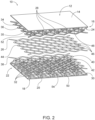
- Figs. 2-3 an illustrative, non-exclusive example of a sandwich panel 10.
- the reference numerals from the schematic illustration of Fig. 1 are used to designate corresponding parts of the example sandwich panel 10; however, the example of Figs. 2-3 are non-exclusive and do not limit sandwich panels 10 to the illustrated embodiment of Figs. 2-3 . That is, sandwich panels 10 are not limited to the specific embodiment of Figs. 2-3 , and sandwich panels 10 may incorporate any number of the various aspects, configurations, characteristics, properties, etc. of sandwich panels 10 that are illustrated in and discussed with reference to the schematic representations of Fig. 1 and/or the embodiment of Figs.
- example sandwich panel 10 is an example of a sandwich panel 10 whose microtruss structures 16, 22 comprise nodes 28, 32, whose truss elements 24, 30 define square pyramids 52, 54, whose microtruss panels 12, 18 comprise medial skins 34, 38 having medial-skin voids 35, 42, and whose damping film 26 also similarly includes damping-film voids 46 that coincide with the medial-skin voids 35, 42.
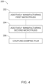
- Fig. 4 schematically provides a flowchart that represents illustrative, non-exclusive examples of a method 200 for additively manufacturing sandwich panels 10 and/or sandwich-panel assemblies 100 according to the present disclosure. Not all methods according to the present disclosure are required to include the steps illustrated. The methods and steps illustrated in Fig. 4 are not limiting and other methods and steps are within the scope of the present disclosure, including methods having greater than or fewer than the number of steps illustrated, as understood from the discussions herein.
- method 200 comprises additively manufacturing 202 the first microtruss panel 12, additively manufacturing 204 the second microtruss panel 18, and coupling 206 the damping film 26 between the first microtruss panel 12 and the second microtruss panel 18.
- any additive manufacturing techniques may be used to form the first microtruss panel 12 and the second microtruss panel 18, such as discussed herein.
- the first truss elements 24 of the first microtruss structure 16 are configured such that support structures are not required during the additively manufacturing 202 of the first microtruss panel 12.
- support structures refer to structures that support and/or stabilize other portions of an object being additively manufactured.
- the first medial skin 34 may be entirely supported by the first truss elements 24 during the additively manufacturing 202 of the first microtruss panel 12.
- a perimeter of the first medial skin 34 does not extend past a perimeter of the first outer skin 14 such that the first microtruss structure 16 acts as a support structure for first medial skin 34 during the additively manufacturing 202.
- the second truss elements 30 of the second microtruss structure 22 are configured such that support structures are not required during the additively manufacturing 204 of the second microtruss panel 18.
- the second medial skin 38 may be entirely supported by the second truss elements 30 during the additively manufacturing 204 of the second microtruss panel 18, thereby eliminating the need for removing support structures post-manufacturing.
- a perimeter of the second medial skin 38 does not extend past a perimeter of the second outer skin 20 such that second microtruss structure 22 acts as a support structure for the second medial skin 38 during the additively manufacturing 204.
- the coupling 206 may comprise adhering the damping film 26 to the first microtruss panel 12 and to the second microtruss panel 18 with an adhesive.
- the damping film 26 may be held in place between and engaged with the first microtruss panel 12 and the second microtruss panel 18 by clamping or otherwise fastening the first microtruss panel 12 to the second microtruss panel 18.
- the terms “adapted” and “configured” mean that the element, component, or other subject matter is designed and/or intended to perform a given function. Thus, the use of the terms “adapted” and “configured” should not be construed to mean that a given element, component, or other subject matter is simply “capable of” performing a given function but that the element, component, and/or other subject matter is specifically selected, created, implemented, utilized, programmed, and/or designed for the purpose of performing the function. It is also within the scope of the present disclosure that elements, components, and/or other recited subject matter that is recited as being adapted to perform a particular function may additionally or alternatively be described as being configured to perform that function, and vice versa. Similarly, subject matter that is recited as being configured to perform a particular function may additionally or alternatively be described as being operative to perform that function.
- the term "and/or" placed between a first entity and a second entity means one of (1) the first entity, (2) the second entity, and (3) the first entity and the second entity.
- Multiple entries listed with “and/or” should be construed in the same manner, i.e., "one or more" of the entities so conjoined.
- Other entities optionally may be present other than the entities specifically identified by the "and/or” clause, whether related or unrelated to those entities specifically identified.
- a reference to "A and/or B,” when used in conjunction with open-ended language such as “comprising,” may refer, in one example, to A only (optionally including entities other than B); in another example, to B only (optionally including entities other than A); in yet another example, to both A and B (optionally including other entities).
- These entities may refer to elements, actions, structures, steps, operations, values, and the like.
Landscapes
- Chemical & Material Sciences (AREA)
- Engineering & Computer Science (AREA)
- Manufacturing & Machinery (AREA)
- Materials Engineering (AREA)
- Laminated Bodies (AREA)
Abstract
Description
- The present disclosure relates to sandwich panels and methods of manufacturing sandwich panels.
- Due to their high structural rigidity and low mass, sandwich panels are used to construct a variety of components in various industries, such as in the manufacture of aircraft, spacecraft, marine vehicles, land vehicles, and other apparatuses. Various equipment may be mounted to sandwich panels, and in some applications, the equipment may impart undesirable vibrations through the sandwich panels.
- Sandwich panels according to the present disclosure comprise a first microtruss panel, a second microtruss panel, and a damping film. The first microtruss panel comprises a first outer skin and a first microtruss structure integral with the first outer skin. The second microtruss panel comprises a second outer skin and a second microtruss structure integral with the second outer skin, wherein the second microtruss structure comprises second truss elements. The damping film is positioned between and engaged with the first microtruss panel and the second microtruss panel opposite the first outer skin and the second outer skin.
- Methods for manufacturing sandwich panels according to the present disclosure comprise additively manufacturing a first microtruss panel, additively manufacturing a second microtruss panel, and coupling a damping film between the first microtruss panel and the second microtruss panel.
-
-
Fig. 1 is a schematic diagram representing sandwich panels according to the present disclosure. -
Fig. 2 is an exploded isometric view of an example sandwich panel. -
Fig. 3 is a cross-sectional view of the example sandwich panel ofFig. 2 . -
Fig. 4 is a flowchart schematically representing methods for manufacturing sandwich panels. -
Fig. 1 schematically illustratessandwich panels 10, sandwich-panel assemblies 100, andapparatuses 110 according to the present disclosure. Generally, inFig. 1 , elements that are likely to be included in a given example are illustrated in solid lines, while elements that are optional to a given example are illustrated in broken lines. However, elements that are illustrated in solid lines are not essential to all examples of the present disclosure, and an element shown in solid lines may be omitted from a particular example without departing from the scope of the present disclosure. - As schematically illustrated in
Fig. 1 , asandwich panel 10 may be a component of a sandwich-panel assembly 100 and/or anapparatus 110. For example, a sandwich-panel assembly 100 may comprise asandwich panel 10 andequipment 102 that is operatively coupled to thesandwich panel 10. Examples ofapparatuses 110, which may include one ormore sandwich panels 10 and/or one or more sandwich-panel assemblies 100, include, but not are limited to, vehicles such as spacecraft, aircraft, marine vehicles, and land vehicles, as well as equipment, machinery, buildings, etc.Sandwich panels 10 may be structural panels of anapparatus 110 and/or may be used as an equipment panel within anapparatus 110, that is, for securingequipment 102 thereto. Illustrative non-exclusive examples ofequipment 102 include pumps, compressors, fans, motors, fly wheel assemblies, reciprocators, and other equipment that may create and/or transmit vibrations to asandwich panel 10 to which it is coupled; however,sandwich panels 10 are not limited to being used with vibration-inducing equipment. - As schematically illustrated in
Fig. 1 ,sandwich panels 10 comprise at least afirst microtruss panel 12, asecond microtruss panel 18, and adamping film 26 that is positioned between and engaged with thefirst microtruss panel 12 and thesecond microtruss panel 18. In some examples, thefirst microtruss panel 12 forms a first percentage of the core of thesandwich panel 10 and thesecond microtruss panel 18 forms a second percentage of the core of thesandwich panel 10. In some such examples, thedamping film 26 may form the remaining percentage of thesandwich panel 10. Thedamping film 26 is provided to attenuate vibrations emanating fromequipment 102 coupled to thesandwich panel 10. The representation of thefirst microtruss panel 12 and thesecond microtruss panel 18 inFig. 1 are schematic in nature and do not limit the microtruss panels to the schematically illustrated configuration. For example, while thefirst microtruss panel 12, thesecond microtruss panel 18, and thesandwich panel 10 itself are schematically represented in a generally flat or planar configuration inFig. 1 ,sandwich panels 10 and their component parts may take any various configurations, including curved and complex configurations.
Thefirst microtruss panel 12 may be substantially identical to thesecond microtruss panel 18. As used herein, "substantially identical" includes at least 75% of the recited similarity or relationship. For example, afirst microtruss panel 12 that is substantially identical to asecond microtruss panel 18 includes afirst microtruss panel 12 that is 75-100% identical to asecond microtruss panel 18. - As schematically represented in
Fig. 1 , thefirst microtruss panel 12 comprises a firstouter skin 14 and afirst microtruss structure 16 that is integral with the firstouter skin 14, and thefirst microtruss structure 16 comprisesfirst truss elements 24. Similarly, thesecond microtruss panel 18 comprises a secondouter skin 20 and asecond microtruss structure 22 that is integral with the secondouter skin 20, and thesecond microtruss structure 22 comprisessecond truss elements 30. In some examples, the firstouter skin 14 and thefirst microtruss structure 16 of thefirst microtruss panel 12 are substantially identical with the secondouter skin 20 and thesecond microtruss structure 22 of thesecond microtruss panel 18. - The outer skins of microtruss panels are expansive thin layers of material, from which at least a subset of the truss elements of the microtruss structures extend. The outer skins additionally or alternatively may be described as sheets or facesheets. The
outer skins sandwich panels 10 provide surfaces to whichequipment 102 may be mounted and carry in-plane and bending loads applied tosandwich panels 10, whereas the microtruss structures 16, 22 (i.e., the core) ofsandwich panels 10 react out-of-plane shear loads. - In some examples, the
outer skins outer skins outer skins mounting equipment 102. - As schematically illustrated in dashed lines in
Fig. 1 , the firstouter skin 14 may comprise a plurality of first-outer-skin ridges 48. Similarly, the secondouter skin 20 may comprise a plurality of second-outer-skin ridges 50. Such ridges additionally or alternatively may be described as ribs or reinforcing ribs. When present, theridges outer skins sandwich panel 10. For example,ridges outer skins skin ridges 48 provides stability for the firstouter skin 14 during manufacturing and use. Each ridge of the plurality of first-outer-skin ridges 48 may be integrally connected to the firstouter skin 14 and/or to two or more truss elements of the plurality oftruss elements 24. In some examples, each ridge of the plurality of first-outer-skin ridges 48 extends between twotruss elements nodes 28. - Microtruss structures, which also may be referred to as microlattice structures, are structures with dimensions close to or within a range of millimeters to micrometers and having a periodic open cell structure with interconnected truss elements, which also may be referred to as struts. Microtruss structures additionally or alternatively may be described as space structures or 3D truss structures and as having a repeating pattern of a plurality of truss elements intersecting at a plurality of nodes.
-
Microtruss structures microtruss structures sandwich panel 10. - As schematically illustrated in
Fig. 1 , in some examples, thefirst microtruss structure 16 comprises, or defines,first nodes 28 at intersections of two or morefirst truss elements 24, and thesecond microtruss structure 22 comprisessecond nodes 32 at intersections of two or moresecond truss elements 30. Accordingly, the microtruss structures ofsandwich panels 10 may be described as an open-cell configuration. In some examples, truss elements are circular in a cross-section. The cross-section ofindividual truss elements 24 and/or 30 may vary in diameter and/or thickness along the length of atruss element 24 and/or 30. For example,first truss elements 24 may be larger in diameter nearer to firstouter skin 14 and thinner nearer to the firstmedial skin 34, or vice versa. The density, diameter, and/or length oftruss elements 24 and/or 30 may vary depending on the application. For example, the density, diameter, and/or length oftruss elements 24 and/or 30 may vary depending on expected stresses on and/or in thesandwich panel 10. In some such examples, the density, diameter, and/or length oftruss elements respective microtruss structures first microtruss structure 16 may be different from the thickness of thesecond microtruss structure 22. - While
Fig. 1 schematically illustrates each ofmicrotruss structures microtruss structures sandwich panels 10. In some examples, a thickness of eachmicrotruss structures first microtruss structure 16 and thesecond microtruss structure 22 need not have the same number of layers of cells or otherwise be identically constructed, depending on the ultimate application for asandwich panel 10. For example, thefirst microtruss structure 16 may have a thickness greater than thesecond microtruss structure 22. In some examples, the density of cells formicrotruss structures 16 and/or 18 varies. For example, the density of cells may vary depending on the density of the truss elements. - In some examples, the
first truss elements 24 and the firstouter skin 14 define a plurality of first-microtruss-panelsquare pyramids 52. Similarly, in some examples, thesecond truss elements 30 and the secondouter skin 20 define a plurality of second-microtruss-panelsquare pyramids 54. That is, the open cells of the microtruss structures may be square pyramids, although other shapes also may be utilized and incorporated into the microtruss structures ofsandwich panels 10. For example, thefirst truss elements 24 and the firstouter skin 14 may define a plurality of first-microtruss-panel triangular pyramids, rectangular prisms, or prism shapes, etc. Similarly, thesecond truss elements 30 and the secondouter skin 20 may define a plurality of second-microtruss-panel triangular pyramids, rectangular prisms, or other prism shapes, etc. In some examples, the triangular faces of the plurality of first-microtruss-panelsquare pyramids 52 are configured to be equilateral triangles. Similarly, in some examples, the triangular faces of the plurality of second-microtruss-panelsquare pyramids 54 are configured to be equilateral triangles. - As optionally represented in dashed lines in
Fig. 1 , in some examples, thefirst microtruss panel 12 further comprises a firstmedial skin 34 that is integral with thefirst microtruss structure 16 opposite the firstouter skin 14. That is, thefirst microtruss structure 16 may be sandwiched between the firstouter skin 14 and the firstmedial skin 34. In some such examples, at least a subset of thefirst truss elements 24 terminate at the firstmedial skin 34, such as with at least a subset of thefirst nodes 28 coinciding with the firstmedial skin 34. However, in other examples the firstmedial skin 34 may not coincide withfirst nodes 28, and instead, at least a subset of thefirst truss elements 24 may terminate at the firstmedial skin 34 without a correspondingfirst node 28. - The first
medial skin 34, when present, provides structure for operative coupling of thefirst microtruss panel 12 to the dampingfilm 26 beyond just thefirst nodes 28 or terminal ends of thefirst truss elements 24. Although not represented inFig. 1 , in some examples, the firstmedial skin 34 defines a first-medial-skin lattice structure 36 having a plurality of first-medial-skin voids 35. In some such examples, the first-medial-skin lattice structure 36 has a cross-shape, with the intersections of each cross located and integrally connected to a node of the plurality offirst nodes 28. By having a lattice structure, the mass of the firstmedial skin 34 is reduced, and the sizes of the first-medial-skin voids 35 may be selected such that the resulting surface area of the firstmedial skin 34 is sufficient for operative coupling to the dampingfilm 26. Alternatively, the firstmedial skin 34 may have a continuous surface, and such a continuous surface may be substantially identical to the firstouter skin 14. - Similarly, as optionally represented in dashed lines in
Fig. 1 , in some examples, thesecond microtruss panel 18 further comprises a secondmedial skin 38 that is integral with thesecond microtruss structure 22 opposite the secondouter skin 20. That is, thesecond microtruss structure 22 may be sandwiched between the secondouter skin 20 and the secondmedial skin 38. In some such examples, at least a subset of thesecond truss elements 30 terminate at the secondmedial skin 38, such as with at least a subset of thesecond nodes 32 coinciding with the secondmedial skin 38. However, in other examples the secondmedial skin 38 may not coincide with thesecond nodes 32, and instead, at least a subset of thesecond truss elements 30 may terminate at the secondmedial skin 38 without a correspondingsecond node 32. - As with the first
medial skin 34, the secondmedial skin 38, when present, provides structure for operative coupling of thesecond microtruss panel 18 to the dampingfilm 26 beyond just thesecond nodes 32 or terminal ends of thesecond truss elements 30. Although not represented inFig. 1 , in some examples, like the firstmedial skin 34, the secondmedial skin 38 defines a second-medial-skin lattice structure 40 having a plurality of second-medial-skin voids 42. In some such examples, the lattice structure has a cross-shape, with the intersections of each cross located and integrally connected to a node of the plurality ofsecond nodes 32. By having a lattice structure, the mass of the secondmedial skin 38 is reduced, and the sizes of the second-medial-skin voids 42 may be selected such that the resulting surface area of the secondmedial skin 38 is sufficient for operative coupling to the dampingfilm 26. Alternatively, the secondmedial skin 38 may have a continuous surface, and such a continuous surface may be substantially identical to the secondouter skin 20. - The damping
film 26 of thesandwich panel 10 comprises any suitable films, sheets, skins, etc. configured to attenuate vibrations in thesandwich panel 10. In particular, the dampingfilm 26 may be made of any material suitable for attenuating vibrations, such as (but not limited to) acrylic tape and/or synthetic rubber. In some examples, the material, thickness, and/or durometer of the dampingfilm 26 are selected based on the type of loading to be used on the sandwich panel 10 (e.g., the types of equipment expected to be used) and/or vibrational modes. For example, the material, thickness, and/or durometer of the dampingfilm 26 may be selected based on vibrations such as broad range random vibrations (20-2000Hz), sine vibrations (10-100Hz), vibrations from the acoustic environment, vibrational frequencies generated from resonance equipment, and/or specific frequencies due to mountedequipment 102. - In some examples, the damping
film 26 is configured to attenuate vibrations present in thesandwich panel 10. In some such examples, the dampingfilm 26 is configured to attenuate vibrations through friction. For example, the dampingfilm 26 may be configured to attenuate vibrations through internal friction and converting vibrational energy into heat. Alternatively, the dampingfilm 26 may be configured to attenuate vibrations through resisting and/or preventing movement in thefirst microtruss panel 12 and/or thesecond microtruss panel 18. In some such examples, dampingfilm 26 may be configured to absorb and dissipate the shear strain energy by, for example, converting the energy into heat. In some examples, the dampingfilm 26 is configured to achieve a damping level that is determined by the mountedequipment 102. Possible damping levels include underdamping, overdamping, and/or critical damping. In some examples, the dampingfilm 26 is configured to prevent vibrations from transferring to the surrounding environment from thesandwich panel 10, as well as to reduce vibrational interference on the mounted equipment 102.The dampingfilm 26 may be positioned to dampen different vibrational modes. For example, the dampingfilm 26 may be positioned on the neutral axis of thesandwich panel 10, such that certain vibrational modes are damped. For example, the dampingfilm 26 may be equidistant from the firstouter skin 14 and the secondouter skin 20. In other examples, the neutral axis of thesandwich panel 10 may not be equidistant from the firstouter skin 14 and the secondouter skin 20. In some examples, dampingfilm 26 is positioned to absorb shear strain energy insandwich panel 10. For example, in a symmetric sandwich panel, the maximum transverse shear occurs at the centerline or the center plane (i.e., equidistant between the firstouter skin 14 the secondouter skin 20, and dampingfilm 26 may be positioned at the centerline or the center plane so to absorb the shear strain energy. - In some examples, the damping
film 26 defines a damping-film lattice structure 44 having a plurality of damping-film voids 46, as schematically indicated inFig. 1 . By having such a lattice structure, the mass of the dampingfilm 26 is reduced, and the sizes of the damping-film voids 46 may be selected to result in a desired level of damping by the dampingfilm 26. Additionally, when asandwich panel 10 comprises optionalmedial skins film lattice structure 44 may correspond with a first-medial-skin lattice structure 36 and a second-medial-skin lattice structure 40. - In some examples, the damping
film 26 is adhered to thefirst microtruss panel 12 and to thesecond microtruss panel 18. In some examples, being adhered to themicrotruss panels film 26 within thesandwich panel 10. For example, differences in the thicknesses between themicrotruss structures film 26 such that the dampingfilm 26 is not equidistant from the firstouter skin 14 and the secondouter skin 20 when adhered to themicrotruss panels microtruss panels film 26 at the centerline of thesandwich panel 10. - With continued reference to
Fig. 1 , in some examples, thefirst microtruss panel 12 comprises one or more first-microtruss-panel mounts 104 for operative coupling ofequipment 102 to thesandwich panel 10. Similarly and as also schematically and optionally represented inFig. 1 , in some examples, thesecond microtruss panel 18 comprises one or more second-microtruss-panel mounts 106 for operative coupling ofequipment 102 to thesandwich panel 10. In some examples,such mounts outer skins such mounts outer skins mounts equipment 102 to be coupled to a sandwich panel, including (but not limited to), inserts, through-bushings, embedded fittings, threaded mounts, etc. - Turning now to
Figs. 2-3 , an illustrative, non-exclusive example of asandwich panel 10. Where appropriate, the reference numerals from the schematic illustration ofFig. 1 are used to designate corresponding parts of theexample sandwich panel 10; however, the example ofFigs. 2-3 are non-exclusive and do not limitsandwich panels 10 to the illustrated embodiment ofFigs. 2-3 . That is,sandwich panels 10 are not limited to the specific embodiment ofFigs. 2-3 , andsandwich panels 10 may incorporate any number of the various aspects, configurations, characteristics, properties, etc. ofsandwich panels 10 that are illustrated in and discussed with reference to the schematic representations ofFig. 1 and/or the embodiment ofFigs. 2-3 , as well as variations thereof, without requiring the inclusion of all such aspects, configurations, characteristics, properties, etc. For the purpose of brevity, each previously discussed component, part, portion, aspect, region, etc. or variants thereof may not be discussed, illustrated, and/or labeled again with respect to the example ofFigs. 2-3 ; however, it is within the scope of the present disclosure that the previously discussed features, variants, etc. may be utilized with the example ofFigs. 2-3 . - As illustrated in
Figs. 2-3 ,example sandwich panel 10 is an example of asandwich panel 10 whosemicrotruss structures nodes truss elements square pyramids microtruss panels medial skins skin voids film 26 also similarly includes damping-film voids 46 that coincide with the medial-skin voids -
Fig. 4 schematically provides a flowchart that represents illustrative, non-exclusive examples of amethod 200 for additively manufacturingsandwich panels 10 and/or sandwich-panel assemblies 100 according to the present disclosure. Not all methods according to the present disclosure are required to include the steps illustrated. The methods and steps illustrated inFig. 4 are not limiting and other methods and steps are within the scope of the present disclosure, including methods having greater than or fewer than the number of steps illustrated, as understood from the discussions herein. - As seen in
Fig. 4 ,method 200 comprises additively manufacturing 202 thefirst microtruss panel 12, additively manufacturing 204 thesecond microtruss panel 18, andcoupling 206 the dampingfilm 26 between thefirst microtruss panel 12 and thesecond microtruss panel 18. - Any additive manufacturing techniques may be used to form the
first microtruss panel 12 and thesecond microtruss panel 18, such as discussed herein. - In some examples, the
first truss elements 24 of thefirst microtruss structure 16 are configured such that support structures are not required during the additively manufacturing 202 of thefirst microtruss panel 12. Herein, support structures refer to structures that support and/or stabilize other portions of an object being additively manufactured. For example, in examples ofmethods 200 in which thesandwich panel 10 includes a firstmedial skin 34, the firstmedial skin 34 may be entirely supported by thefirst truss elements 24 during the additively manufacturing 202 of thefirst microtruss panel 12. Additionally or alternatively, a perimeter of the firstmedial skin 34 does not extend past a perimeter of the firstouter skin 14 such that thefirst microtruss structure 16 acts as a support structure for firstmedial skin 34 during theadditively manufacturing 202. Having thefirst microtruss panel 12 fully self-supported during the additively manufacturing 202 eliminates the need for removing support structures post-manufacturing. Similarly, in some examples, thesecond truss elements 30 of thesecond microtruss structure 22 are configured such that support structures are not required during the additively manufacturing 204 of thesecond microtruss panel 18. For example, in examples ofmethods 200 in which thesandwich panel 10 includes a secondmedial skin 38, the secondmedial skin 38 may be entirely supported by thesecond truss elements 30 during the additively manufacturing 204 of thesecond microtruss panel 18, thereby eliminating the need for removing support structures post-manufacturing. Additionally or alternatively, a perimeter of the secondmedial skin 38 does not extend past a perimeter of the secondouter skin 20 such thatsecond microtruss structure 22 acts as a support structure for the secondmedial skin 38 during theadditively manufacturing 204. - The
coupling 206 may comprise adhering the dampingfilm 26 to thefirst microtruss panel 12 and to thesecond microtruss panel 18 with an adhesive. Alternatively, the dampingfilm 26 may be held in place between and engaged with thefirst microtruss panel 12 and thesecond microtruss panel 18 by clamping or otherwise fastening thefirst microtruss panel 12 to thesecond microtruss panel 18. - Illustrative, non-exclusive examples of inventive subject matter according to the present disclosure are described in the following enumerated paragraphs:
- A. A sandwich panel, comprising:
- a first microtruss panel comprising a first outer skin and a first microtruss structure integral with the first outer skin, wherein the first microtruss structure comprises first truss elements;
- a second microtruss panel comprising a second outer skin and a second microtruss structure integral with the second outer skin, wherein the second microtruss structure comprises second truss elements; and
- a damping film positioned between and engaged with the first microtruss panel and the second microtruss panel opposite the first outer skin and the second outer skin.
- A1. The sandwich panel of paragraph A,
- wherein the first microtruss structure further comprises first nodes at intersections of two or more first truss elements; and
- wherein the second microtruss structure comprises second nodes at intersections of two or more second truss elements.
- A1.1. The sandwich panel of paragraph A1, wherein the first truss elements and the first outer skin define a plurality of first-microtruss-panel square pyramids.
- A1.2. The sandwich panel of any of paragraphs A1-A1.1, wherein the second truss elements and the second outer skin define a plurality of second-microtruss-panel square pyramids.
- A2. The sandwich panel of any of paragraphs A-A1.2, wherein the first microtruss panel further comprises a first medial skin integral with the first microtruss structure opposite the first outer skin.
- A2.1. The sandwich panel of paragraph A2, wherein at least a subset of the first truss elements terminate at the first medial skin.
- A2.2. The sandwich panel of any of paragraphs A2-A2.1 when depending from paragraph A1, wherein at least a subset of the first nodes coincide with the first medial skin.
- A2.3. The sandwich panel of any of paragraphs A2-A2.2, wherein the first medial skin defines a first-medial-skin lattice structure having a plurality of first-medial-skin voids.
- A3. The sandwich panel of any of paragraphs A-A2.3, wherein the second microtruss panel further comprises a second medial skin integral with the second microtruss structure opposite the second outer skin.
- A3.1. The sandwich panel of paragraph A3, wherein at least a subset of the second truss elements terminate at the second medial skin.
- A3.2. The sandwich panel of any of paragraphs A3-A3.1 when depending from paragraph A1, wherein at least a subset of the second nodes coincide with the second medial skin.
- A3.3. The sandwich panel of any of paragraphs A3-A3.2, wherein the second medial skin defines a second-medial-skin lattice structure having a plurality of second-medial-skin voids.
- A4. The sandwich panel of any of paragraphs A-A3.3, wherein the damping film defines a damping-film lattice structure having a plurality of damping-film voids.
- A4.1. The sandwich panel of paragraph A4 when depending from paragraph A2.3, wherein the damping-film lattice structure coincides with the first-medial-skin lattice structure.
- A4.2. The sandwich panel of any of paragraphs A4-A4.1 when depending from paragraph A3.3, wherein the damping-film lattice structure coincides with the second-medial-skin lattice structure.
- A5. The sandwich panel of any of paragraphs A-A4.2, wherein the damping film is equidistant from the first outer skin and the second outer skin.
- A6. The sandwich panel of any of paragraphs A-A5, wherein the first outer skin and the first microtruss structure of the first microtruss panel are substantially identical with the second outer skin and the second microtruss structure of the second microtruss panel.
- A7. The sandwich panel of any of paragraphs A-A6, wherein the damping film is adhered to the first microtruss panel and to the second microtruss panel.
- A8. The sandwich panel of any of paragraphs A-A7, wherein the damping film is constructed of acrylic tape or synthetic rubber materials.
- A9. The sandwich panel of any of paragraphs A-A8, wherein the first outer skin comprises a plurality of first-outer-skin ridges extending toward the second microtruss panel.
- A9.1. The sandwich panel of paragraph A9, wherein a subset of the plurality of first-outer-skin ridges extends linearly between intersections of the first truss elements and the first outer skin.
- A10. The sandwich panel of any of paragraphs A-A9.1, wherein the second outer skin comprises a plurality of second-outer-skin ridges extending toward the first microtruss panel.
- A10.1. The sandwich panel of paragraph A10, wherein a subset of the plurality of second-outer-skin ridges extends linearly between intersections of the second truss elements and the second outer skin.
- A11. The sandwich panel of any of paragraphs A-A10.1, wherein the first microtruss panel and the second microtruss panel are constructed of metal.
- A11.1. The sandwich panel of paragraph A11, wherein the first microtruss panel and the second microtruss panel are constructed of aluminum or an aluminum alloy.
- A12. The sandwich panel of any of paragraphs A-A11.1, wherein the first microtruss panel comprises one or more first-microtruss-panel mounts for operative coupling of equipment to the sandwich panel.
- A12.1. The sandwich panel of paragraph A12, wherein the one or more first-microtruss-panel mounts are integral with the first outer skin.
- A12.2. The sandwich panel of paragraph A12, wherein the one or more first-microtruss-panel mounts are operatively coupled to the first outer skin.
- A13. The sandwich panel of any of paragraphs A-A12.2, wherein the second microtruss panel comprises one or more second-microtruss-panel mounts for operative coupling of the equipment to the sandwich panel.
- A13.1. The sandwich panel of paragraph A13, wherein the one or more second-microtruss-panel mounts are integral with the second outer skin.
- A13.2. The sandwich panel of paragraph A13, wherein the one or more second-microtruss-panel mounts are operatively coupled to the second outer skin.
- B. A sandwich-panel assembly, comprising:
- the sandwich panel of any of paragraphs A-A11.1; and
- equipment operatively coupled to the sandwich panel.
- B1. The sandwich-panel assembly of paragraph B, wherein the first microtruss panel comprises one or more first-microtruss-panel mounts, and wherein the equipment is operatively mounted to the one or more first-microtruss-panel mounts.
- B1.1. The sandwich-panel assembly of paragraph B1, wherein the one or more first-microtruss-panel mounts are integral with the first outer skin.
- B1.2. The sandwich-panel assembly of paragraph B1, wherein the one or more first-microtruss-panel mounts are operatively coupled to the first outer skin.
- B2. The sandwich-panel assembly of any of paragraphs B-B1.2., wherein the second microtruss panel comprises one or more second-microtruss-panel mounts, and wherein the equipment is operatively mounted to the one or more second-microtruss-panel mounts.
- B2.1. The sandwich-panel assembly of paragraph B2, wherein the one or more second-microtruss-panel mounts are integral with the second outer skin.
- B2.2. The sandwich-panel assembly of paragraph B2, wherein the one or more second-microtruss-panel mounts are operatively coupled to the second outer skin.
- B3. The sandwich-panel assembly of any of paragraphs B-B2.2, wherein the equipment is configured to impart a vibration to the sandwich panel.
- B3.1. The sandwich-panel assembly of paragraph B3., wherein the damping film is configured to attenuate vibrations imparted to the sandwich-panel assembly by the equipment.
- C. An apparatus, comprising the sandwich-panel assembly of any of paragraphs B-B3.1.
- D. A method of manufacturing the sandwich panel of any of paragraphs A-A13.2 or the sandwich-panel assembly of any of paragraphs B-B3.1, comprising:
- additively manufacturing the first microtruss panel;
- additively manufacturing the second microtruss panel; and
- coupling the damping film between the first microtruss panel and the second microtruss panel.
- E. Use of the sandwich panel of any of paragraphs A-A13.2 to attenuate vibrations from equipment operatively coupled to the sandwich panel.
- As used herein, the terms "adapted" and "configured" mean that the element, component, or other subject matter is designed and/or intended to perform a given function. Thus, the use of the terms "adapted" and "configured" should not be construed to mean that a given element, component, or other subject matter is simply "capable of" performing a given function but that the element, component, and/or other subject matter is specifically selected, created, implemented, utilized, programmed, and/or designed for the purpose of performing the function. It is also within the scope of the present disclosure that elements, components, and/or other recited subject matter that is recited as being adapted to perform a particular function may additionally or alternatively be described as being configured to perform that function, and vice versa. Similarly, subject matter that is recited as being configured to perform a particular function may additionally or alternatively be described as being operative to perform that function.
- As used herein, the term "and/or" placed between a first entity and a second entity means one of (1) the first entity, (2) the second entity, and (3) the first entity and the second entity. Multiple entries listed with "and/or" should be construed in the same manner, i.e., "one or more" of the entities so conjoined. Other entities optionally may be present other than the entities specifically identified by the "and/or" clause, whether related or unrelated to those entities specifically identified. Thus, as a nonlimiting example, a reference to "A and/or B," when used in conjunction with open-ended language such as "comprising," may refer, in one example, to A only (optionally including entities other than B); in another example, to B only (optionally including entities other than A); in yet another example, to both A and B (optionally including other entities). These entities may refer to elements, actions, structures, steps, operations, values, and the like.
- The various disclosed elements of apparatuses and steps of methods disclosed herein are not required to all apparatuses and methods according to the present disclosure, and the present disclosure includes all novel and non-obvious combinations and subcombinations of the various elements and steps disclosed herein. Moreover, one or more of the various elements and steps disclosed herein may define independent inventive subject matter that is separate and apart from the whole of a disclosed apparatus or method. Accordingly, such inventive subject matter is not required to be associated with the specific apparatuses and methods that are expressly disclosed herein, and such inventive subject matter may find utility in apparatuses and/or methods that are not expressly disclosed herein.
Claims (15)
- A sandwich panel (10), comprising:a first microtruss panel (12) comprising a first outer skin (14) and a first microtruss structure (16) integral with the first outer skin (14), wherein the first microtruss structure (16) comprises first truss elements (24);a second microtruss panel (18) comprising a second outer skin (20) and a second microtruss structure (22) integral with the second outer skin (20), wherein the second microtruss structure (22) comprises second truss elements (30); anda damping film (26) positioned between and engaged with the first microtruss panel (12) and the second microtruss panel (18) opposite the first outer skin (14) and the second outer skin (20).
- The sandwich panel (10) of claim 1,wherein the first microtruss structure (16) further comprises first nodes (28) at intersections of two or more first truss elements (24); andwherein the second microtruss structure (22) comprises second nodes (32) at intersections of two or more second truss elements (30).
- The sandwich panel (10) of claim 2, wherein the first truss elements (24) and the first outer skin (14) define a plurality of first-microtruss-panel square pyramids (52).
- The sandwich panel (10) of claim 2 or 3, wherein the second truss elements (30) and the second outer skin (20) define a plurality of second-microtruss-panel square pyramids (54).
- The sandwich panel (10) of any preceding claim, wherein the first microtruss panel (12) further comprises a first medial skin (34) integral with the first microtruss structure (16) opposite the first outer skin (14).
- The sandwich panel (10) of claim 5, wherein at least a subset of the first truss elements (24) terminate at the first medial skin (34); and/or wherein the first microtruss structure (16) further comprises first nodes (28) at intersections of two or more first truss elements (24); and
wherein at least a subset of the first nodes (28) coincide with the first medial skin (34). - The sandwich panel (10) of claim 5, wherein the first medial skin (34) defines a first-medial-skin lattice structure (36) having a plurality of first-medial-skin voids (35); and optionallywherein the second microtruss panel (18) further comprises a second medial skin (38) integral with the second microtruss structure (22) opposite the second outer skin (20); andwherein the second medial skin (38) defines a second-medial-skin lattice structure (40) having a plurality of second-medial-skin voids (42).
- The sandwich panel (10) of any preceding claim, wherein the damping film (26) defines a damping-film lattice structure (44) having a plurality of damping-film voids (46).
- The sandwich panel (10) of claim 8,wherein the first microtruss panel (12) further comprises a first medial skin (34) integral with the first microtruss structure (16) opposite the first outer skin (14);wherein the first medial skin (34) defines a first-medial-skin lattice structure (36) having a plurality of first-medial-skin voids (35);wherein the second microtruss panel (18) further comprises a second medial skin (38) integral with the second microtruss structure (22) opposite the second outer skin (20);wherein the second medial skin (38) defines a second-medial-skin lattice structure (40) having a plurality of second-medial-skin voids (42); andwherein the damping-film lattice structure (44) coincides with the first-medial-skin lattice structure (36) and with the second-medial-skin lattice structure (40).
- The sandwich panel (10) of any preceding claim, wherein the damping film (26) is equidistant from the first outer skin (14) and the second outer skin (20); and/or wherein the damping film (26) is constructed of acrylic tape or synthetic rubber materials..
- The sandwich panel (10) of any preceding claim, wherein the first outer skin (14) and the first microtruss structure (16) of the first microtruss panel (12) are substantially identical with the second outer skin (20) and the second microtruss structure (22) of the second microtruss panel (18); and optionally wherein the damping film (26) is adhered to the first microtruss panel (12) and to the second microtruss panel (18).
- The sandwich panel (10) of any preceding claim, wherein the first outer skin (14) comprises a plurality of first-outer-skin ridges (48) extending toward the second microtruss panel (18); and optionally wherein a subset of the plurality of first-outer-skin ridges (48) extends linearly between intersections of the first truss elements (24) and the first outer skin (14).
- The sandwich panel (10) of any preceding claim, wherein the first microtruss panel (12) and the second microtruss panel (18) are constructed of metal.
- A sandwich-panel assembly (100), comprising:the sandwich panel (10) of any preceding claim; andequipment (102) operatively coupled to the sandwich panel (10).
- A method (200) of manufacturing the sandwich panel (10) of any of claims 1 to 13, comprising:additively manufacturing (202) the first microtruss panel (12);additively manufacturing (204) the second microtruss panel (18); andcoupling (206) the damping film (26) between the first microtruss panel (12) and the second microtruss panel (18).
Applications Claiming Priority (1)
| Application Number | Priority Date | Filing Date | Title |
|---|---|---|---|
| US18/153,916 US12172415B2 (en) | 2023-01-12 | 2023-01-12 | Sandwich panels and methods of manufacturing sandwich panels |
Publications (1)
| Publication Number | Publication Date |
|---|---|
| EP4400302A1 true EP4400302A1 (en) | 2024-07-17 |
Family
ID=89119612
Family Applications (1)
| Application Number | Title | Priority Date | Filing Date |
|---|---|---|---|
| EP23214369.3A Pending EP4400302A1 (en) | 2023-01-12 | 2023-12-05 | Sandwich panels and methods of manufacturing sandwich panels |
Country Status (2)
| Country | Link |
|---|---|
| US (1) | US12172415B2 (en) |
| EP (1) | EP4400302A1 (en) |
Citations (4)
| Publication number | Priority date | Publication date | Assignee | Title |
|---|---|---|---|---|
| US9315213B2 (en) * | 2012-06-21 | 2016-04-19 | Pantero Technologies Inc. | Planar space frame for vehicle structure and housing of components |
| US9352529B2 (en) * | 2014-08-12 | 2016-05-31 | Hrl Laboratories, Llc | Progressive stiffness structural-acoustic sandwich panel |
| US20170136738A1 (en) * | 2014-07-14 | 2017-05-18 | Nippon Steel & Sumitomo Metal Corporation | Sandwich metal sheet |
| US20210187897A1 (en) * | 2018-11-13 | 2021-06-24 | VICIS, Inc. | Custom Manufactured Fit Pods |
Family Cites Families (14)
| Publication number | Priority date | Publication date | Assignee | Title |
|---|---|---|---|---|
| DE3720371A1 (en) | 1987-06-19 | 1989-01-05 | Messerschmitt Boelkow Blohm | Lightweight composite panel and process for the production thereof |
| US8197930B1 (en) | 2007-05-10 | 2012-06-12 | Hrl Laboratories, Llc | Three-dimensional ordered open-cellular structures |
| US7382959B1 (en) | 2006-10-13 | 2008-06-03 | Hrl Laboratories, Llc | Optically oriented three-dimensional polymer microstructures |
| US9375864B2 (en) * | 2007-05-10 | 2016-06-28 | Hrl Laboratories, Llc | Architected materials for enhanced energy absorption |
| US8052089B2 (en) | 2008-11-03 | 2011-11-08 | The Boeing Company | Anti-icing apparatus for honeycomb structures |
| US8268510B2 (en) * | 2008-12-22 | 2012-09-18 | GM Global Technology Operations LLC | Fuel cell fabrication using photopolymer based processes |
| US8092957B2 (en) * | 2009-05-15 | 2012-01-10 | GM Global Technology Operations LLC | Diffusion media formed by photopolymer based processes |
| US8800641B2 (en) | 2009-06-01 | 2014-08-12 | The Boeing Company | Methods and apparatus for a micro-truss based structural insulation layer |
| US8586179B1 (en) | 2010-04-09 | 2013-11-19 | The Boeing Company | Mechanical attachment for micro-truss actively cooled structural insulation layer |
| DE102010015638B4 (en) | 2010-04-20 | 2015-02-12 | Airbus Operations Gmbh | Aircraft cabin plate absorber |
| US9017806B2 (en) | 2012-03-23 | 2015-04-28 | Hrl Laboratories, Llc | High airflow micro-truss structural apparatus |
| US8663539B1 (en) | 2012-04-02 | 2014-03-04 | Hrl Laboratories, Llc | Process of making a three-dimentional micro-truss structure |
| US9321241B2 (en) | 2012-05-11 | 2016-04-26 | The Boeing Company | Ventilated aero-structures, aircraft and associated methods |
| KR101564571B1 (en) * | 2013-07-11 | 2015-10-30 | 한국과학기술원 | Pyramidal kagome structure and its fabricating method |
-
2023
- 2023-01-12 US US18/153,916 patent/US12172415B2/en active Active
- 2023-12-05 EP EP23214369.3A patent/EP4400302A1/en active Pending
Patent Citations (4)
| Publication number | Priority date | Publication date | Assignee | Title |
|---|---|---|---|---|
| US9315213B2 (en) * | 2012-06-21 | 2016-04-19 | Pantero Technologies Inc. | Planar space frame for vehicle structure and housing of components |
| US20170136738A1 (en) * | 2014-07-14 | 2017-05-18 | Nippon Steel & Sumitomo Metal Corporation | Sandwich metal sheet |
| US9352529B2 (en) * | 2014-08-12 | 2016-05-31 | Hrl Laboratories, Llc | Progressive stiffness structural-acoustic sandwich panel |
| US20210187897A1 (en) * | 2018-11-13 | 2021-06-24 | VICIS, Inc. | Custom Manufactured Fit Pods |
Also Published As
| Publication number | Publication date |
|---|---|
| US12172415B2 (en) | 2024-12-24 |
| US20240239079A1 (en) | 2024-07-18 |
Similar Documents
| Publication | Publication Date | Title |
|---|---|---|
| Ren et al. | Quasi-static and sound insulation performance of a multifunctional cylindrical cellular shell with bidirectional negative-stiffness metamaterial cores | |
| US8087494B2 (en) | Method of making a composite panel having subsonic transverse wave speed characteristics | |
| JP3078854B2 (en) | Internal anti-vibration type thin composite longitudinal member | |
| Nikhil et al. | Modal analysis of hybrid laminated composite sandwich plate | |
| JP2006137412A (en) | Thermo-acoustic enclosure | |
| Cherniaev et al. | Multistep optimization of composite drive shaft subject to strength, buckling, vibration and manufacturing constraints | |
| EP3310568A1 (en) | Core material for composite structures | |
| US10480613B2 (en) | Metal isolator with tunable resonant frequencies | |
| US12172415B2 (en) | Sandwich panels and methods of manufacturing sandwich panels | |
| Wang et al. | Analysis and optimization of damping properties of constrained layer damping structures with multilayers | |
| Avramov et al. | Nonlinear vibrations of doubly curved composite sandwich shells with FDM additively manufactured flexible honeycomb core: K. Avramov, B. Uspensky | |
| EP0610402B1 (en) | Improved damping in composite structures through stress coupling | |
| Thamburaj et al. | Effect of material and geometry on the sound and vibration transmission across a sandwich beam | |
| Caliskan et al. | Impact penetration and perforation performance of square sandwich panels with EPS foam core | |
| Sabir et al. | Natural frequencies of square plates with reinforced central holes subjected to inplane loads | |
| Barad et al. | Influence of chiral lattice on modal characteristics of structures | |
| Khatri et al. | Vibration and damping analysis of fiber reinforced composite material conical shells | |
| Bert | Shear deformation and sandwich configuration | |
| Olcott | Improved damping in composite structures through stress coupling, co-cured damping layers, and segmented stiffness layers | |
| PV et al. | Modal analysis of composite sandwich panel | |
| JP6495429B1 (en) | Building material | |
| JPH10138388A (en) | Sandwich type damping metal plate | |
| Diveyev | Sound Transmission Properties of Composite Layered Structures in the Lower Frequency Rangee | |
| Kocher et al. | Reinforced Cutouts in Graphite | |
| Sorohan et al. | Design of commercial hexagonal honeycombs of equal out-of-plane shear moduli |
Legal Events
| Date | Code | Title | Description |
|---|---|---|---|
| PUAI | Public reference made under article 153(3) epc to a published international application that has entered the european phase |
Free format text: ORIGINAL CODE: 0009012 |
|
| STAA | Information on the status of an ep patent application or granted ep patent |
Free format text: STATUS: THE APPLICATION HAS BEEN PUBLISHED |
|
| AK | Designated contracting states |
Kind code of ref document: A1 Designated state(s): AL AT BE BG CH CY CZ DE DK EE ES FI FR GB GR HR HU IE IS IT LI LT LU LV MC ME MK MT NL NO PL PT RO RS SE SI SK SM TR |
|
| STAA | Information on the status of an ep patent application or granted ep patent |
Free format text: STATUS: REQUEST FOR EXAMINATION WAS MADE |
|
| 17P | Request for examination filed |
Effective date: 20250116 |
|
| RIC1 | Information provided on ipc code assigned before grant |
Ipc: B32B 25/04 20060101ALI20250430BHEP Ipc: B32B 15/08 20060101ALI20250430BHEP Ipc: B32B 15/06 20060101ALI20250430BHEP Ipc: B32B 7/05 20190101ALI20250430BHEP Ipc: B32B 7/03 20190101ALI20250430BHEP Ipc: B32B 3/30 20060101ALI20250430BHEP Ipc: B32B 3/26 20060101ALI20250430BHEP Ipc: B32B 3/12 20060101AFI20250430BHEP Ipc: B32B 27/30 20060101ALI20250430BHEP |
|
| STAA | Information on the status of an ep patent application or granted ep patent |
Free format text: STATUS: EXAMINATION IS IN PROGRESS |
|
| 17Q | First examination report despatched |
Effective date: 20250929 |