EP4400238A2 - Drilling apparatus and drilling system - Google Patents
Drilling apparatus and drilling system Download PDFInfo
- Publication number
- EP4400238A2 EP4400238A2 EP23206918.7A EP23206918A EP4400238A2 EP 4400238 A2 EP4400238 A2 EP 4400238A2 EP 23206918 A EP23206918 A EP 23206918A EP 4400238 A2 EP4400238 A2 EP 4400238A2
- Authority
- EP
- European Patent Office
- Prior art keywords
- bearing housing
- drilling apparatus
- tool
- machine tool
- workpiece
- Prior art date
- Legal status (The legal status is an assumption and is not a legal conclusion. Google has not performed a legal analysis and makes no representation as to the accuracy of the status listed.)
- Pending
Links
Images



Classifications
-
- B—PERFORMING OPERATIONS; TRANSPORTING
- B23—MACHINE TOOLS; METAL-WORKING NOT OTHERWISE PROVIDED FOR
- B23B—TURNING; BORING
- B23B35/00—Methods for boring or drilling, or for working essentially requiring the use of boring or drilling machines; Use of auxiliary equipment in connection with such methods
-
- B—PERFORMING OPERATIONS; TRANSPORTING
- B23—MACHINE TOOLS; METAL-WORKING NOT OTHERWISE PROVIDED FOR
- B23B—TURNING; BORING
- B23B39/00—General-purpose boring or drilling machines or devices; Sets of boring and/or drilling machines
- B23B39/14—General-purpose boring or drilling machines or devices; Sets of boring and/or drilling machines with special provision to enable the machine or the drilling or boring head to be moved into any desired position, e.g. with respect to immovable work
-
- B—PERFORMING OPERATIONS; TRANSPORTING
- B23—MACHINE TOOLS; METAL-WORKING NOT OTHERWISE PROVIDED FOR
- B23B—TURNING; BORING
- B23B51/00—Tools for drilling machines
- B23B51/02—Twist drills
-
- B—PERFORMING OPERATIONS; TRANSPORTING
- B23—MACHINE TOOLS; METAL-WORKING NOT OTHERWISE PROVIDED FOR
- B23Q—DETAILS, COMPONENTS, OR ACCESSORIES FOR MACHINE TOOLS, e.g. ARRANGEMENTS FOR COPYING OR CONTROLLING; MACHINE TOOLS IN GENERAL CHARACTERISED BY THE CONSTRUCTION OF PARTICULAR DETAILS OR COMPONENTS; COMBINATIONS OR ASSOCIATIONS OF METAL-WORKING MACHINES, NOT DIRECTED TO A PARTICULAR RESULT
- B23Q11/00—Accessories fitted to machine tools for keeping tools or parts of the machine in good working condition or for cooling work; Safety devices specially combined with or arranged in, or specially adapted for use in connection with, machine tools
- B23Q11/0042—Devices for removing chips
- B23Q11/0046—Devices for removing chips by sucking
-
- B—PERFORMING OPERATIONS; TRANSPORTING
- B25—HAND TOOLS; PORTABLE POWER-DRIVEN TOOLS; MANIPULATORS
- B25J—MANIPULATORS; CHAMBERS PROVIDED WITH MANIPULATION DEVICES
- B25J11/00—Manipulators not otherwise provided for
- B25J11/005—Manipulators for mechanical processing tasks
-
- B—PERFORMING OPERATIONS; TRANSPORTING
- B25—HAND TOOLS; PORTABLE POWER-DRIVEN TOOLS; MANIPULATORS
- B25J—MANIPULATORS; CHAMBERS PROVIDED WITH MANIPULATION DEVICES
- B25J11/00—Manipulators not otherwise provided for
- B25J11/005—Manipulators for mechanical processing tasks
- B25J11/0055—Cutting
-
- B—PERFORMING OPERATIONS; TRANSPORTING
- B25—HAND TOOLS; PORTABLE POWER-DRIVEN TOOLS; MANIPULATORS
- B25J—MANIPULATORS; CHAMBERS PROVIDED WITH MANIPULATION DEVICES
- B25J19/00—Accessories fitted to manipulators, e.g. for monitoring, for viewing; Safety devices combined with or specially adapted for use in connection with manipulators
- B25J19/06—Safety devices
- B25J19/063—Safety devices working only upon contact with an outside object
-
- F—MECHANICAL ENGINEERING; LIGHTING; HEATING; WEAPONS; BLASTING
- F16—ENGINEERING ELEMENTS AND UNITS; GENERAL MEASURES FOR PRODUCING AND MAINTAINING EFFECTIVE FUNCTIONING OF MACHINES OR INSTALLATIONS; THERMAL INSULATION IN GENERAL
- F16C—SHAFTS; FLEXIBLE SHAFTS; ELEMENTS OR CRANKSHAFT MECHANISMS; ROTARY BODIES OTHER THAN GEARING ELEMENTS; BEARINGS
- F16C33/00—Parts of bearings; Special methods for making bearings or parts thereof
- F16C33/30—Parts of ball or roller bearings
- F16C33/66—Special parts or details in view of lubrication
- F16C33/6637—Special parts or details in view of lubrication with liquid lubricant
- F16C33/6659—Details of supply of the liquid to the bearing, e.g. passages or nozzles
-
- B—PERFORMING OPERATIONS; TRANSPORTING
- B23—MACHINE TOOLS; METAL-WORKING NOT OTHERWISE PROVIDED FOR
- B23B—TURNING; BORING
- B23B2215/00—Details of workpieces
- B23B2215/04—Aircraft components
-
- B—PERFORMING OPERATIONS; TRANSPORTING
- B23—MACHINE TOOLS; METAL-WORKING NOT OTHERWISE PROVIDED FOR
- B23B—TURNING; BORING
- B23B2260/00—Details of constructional elements
- B23B2260/128—Sensors
-
- B—PERFORMING OPERATIONS; TRANSPORTING
- B23—MACHINE TOOLS; METAL-WORKING NOT OTHERWISE PROVIDED FOR
- B23B—TURNING; BORING
- B23B2270/00—Details of turning, boring or drilling machines, processes or tools not otherwise provided for
- B23B2270/32—Use of electronics
-
- B—PERFORMING OPERATIONS; TRANSPORTING
- B23—MACHINE TOOLS; METAL-WORKING NOT OTHERWISE PROVIDED FOR
- B23B—TURNING; BORING
- B23B2270/00—Details of turning, boring or drilling machines, processes or tools not otherwise provided for
- B23B2270/36—Identification of tooling or other equipment
Definitions
- the present disclosure is related to a drilling apparatus and methods of use of the drilling apparatus.
- the drilling apparatus enables formation of a close tolerance hole at a location of a structure with limited access, a large offset distance from a drive mechanism for the drilling apparatus to a start location for the hole, or both.
- Machine tools are used during the manufacture of products. Some machine tools include a movable platform and a tool arm (e.g., a robot). Various tools can be attached to end effectors on the tool arm to perform particular tasks.
- a tool arm e.g., a robot.
- holes need to be formed in workpieces at very precise locations and with very close tolerances. Close tolerance holes in relatively small workpieces that are easily moved are often formed using a drill press.
- a drill jig can be used to facilitate formation of close tolerance holes.
- a location of the hole and a shape of the workpiece make the use of drill jigs labor intensive, time consuming, and unreliable to consistently produce holes within a tolerance limit due to deflection during drilling.
- a drilling apparatus includes an attachment box configured to couple to a machine tool.
- the drilling apparatus is configured to facilitate formation of a hole in a workpiece with workpiece structure that results in a large offset distance from a start location of the hole to the machine tool, restricted access to the start location of the hole, or both.
- the drilling apparatus includes a bearing housing coupled to the attachment box.
- the bearing housing includes a pair of bearings.
- the drilling apparatus includes a shaft position through the bearing housing to couple to the bearings of the bearing housing.
- the shaft includes an end effector interface configured to couple to one or more end effectors of the machine tool at a first end of the shaft.
- the shaft includes a tool interface configured to couple to a tool at a second end of the shaft.
- the drilling apparatus also includes an offset foot coupled to the bearing housing.
- a drilling system includes an attachment box to couple to an end effector of a machine tool.
- the drilling system is configured to facilitate formation of a hole in a workpiece with workpiece structure that results in a large offset distance from a start location of the hole to the end effector of the machine tool, restricted access to the start location of the hole, or both.
- the drilling system includes a bearing housing coupled to the attachment box.
- the bearing housing includes a pair of bearings.
- the drilling system includes a shaft positioned through the bearing housing to couple to the bearings of the bearing housing.
- the shaft is configured to couple to a spindle of the machine tool at a first end.
- the drilling system includes a drill bit configured to couple to a second end of the shaft.
- the drilling system also includes an offset foot coupled to the bearing housing.
- the offset foot includes a tip configured to contact the workpiece during use.
- a drilling system includes a machine tool.
- the machine tool includes a spindle.
- the drilling system is configured to facilitate formation of a hole in a workpiece with workpiece structure that results in a large offset distance from the machine tool to a start location of the hole, restricted access to the start location of the hole, or both.
- the drilling system includes an attachment box configured to couple to the machine tool.
- the drilling system includes a bearing housing coupled to the attachment box.
- the bearing housing includes a pair of bearings.
- the drilling system includes a shaft positioned through the bearing housing.
- the shaft is configured to couple to a drill mechanism of the machine tool at a first end of the shaft.
- the drilling system includes a drill bit configured to couple to a second end of the shaft.
- the drilling system also includes an offset foot coupled to the bearing housing.
- the offset foot includes a contact tip configured to contact the workpiece during use.
- a drilling system enables a close tolerance hole to be drilled in a workpiece.
- the drilling system includes a machine tool that positions a drilling apparatus and utilizes the drilling apparatus to facilitate formation of the hole.
- the workpiece may include structure that results in a large offset distance from an end effector interface that couples to the machine tool to the start location of the hole.
- the structure may also result in limited access to the start location of the hole.
- a plurality of tools can be coupled to a tool interface of the drilling apparatus at various times during the process.
- the tools can include a touch probe to determine surface features associated with the workpiece near a start location for the hole to facilitate determination of the start location of the hole, a pen tool to mark the start location where the hole will be formed, and a drill bit used to form the hole.
- fewer tools or additional tools can be coupled to the tool interface during the process of forming the close tolerance hole.
- the machine tool controls travel and a contact location of a contact tip of the drilling apparatus with the workpiece during the process of forming the close tolerance hole.
- An interface between the drilling apparatus and an effector of the machine tool that operates the drilling apparatus can be at a large offset distance from the location of the hole (e.g., 30 inches, 24 inches, or some other offset distance) to enable accommodation of workpiece structure near the location for the hole.
- the machine tool can control movement of the drilling apparatus (e.g., lateral movement relative to the workpiece and movement towards or away from the workpiece) such that placement of the contact tip of the drilling apparatus is at a particular location on the workpiece.
- a body of the drilling apparatus can be close to, but not contacting, the structure of the workpiece.
- a separation distance between a portion of the structure of the workpiece and a body of the drilling apparatus can be about a sixteenth of an inch or greater for a workpiece where the hole is to be formed at a location with limited access to the location of the hole.
- the machine tool provides sufficient force to the drilling apparatus at the contact tip when the drilling apparatus is drilling the hole to counteract torque and drill thrust caused by interaction of the drill bit with the workpiece during formation of the hole and to consistently enable formation of holes that satisfy a tolerance threshold.
- a vacuum system of the machine tool coupled to the drilling apparatus removes cuttings during drilling.
- a fluid system of the machine tool supplies fluid through fluid lines to the drilling apparatus to provide lubrication fluid to bearings of the drilling apparatus, to provide lubrication fluid as a mist to the drill bit to cool the drill bit and facilitate removal of cuttings by the vacuum system, or both.
- drilling apparatus enables consistent formation of close tolerance holes in workpieces.
- a workpiece can include structure that results in a large offset distance from a start location of the hole to an interface between the drilling apparatus and a machine tool that drives the drilling apparatus, restricted access to the start location of the hole, or both.
- the formation of a close tolerance hole in the workpiece using the drilling system is more reliable to satisfy a tolerance threshold, quicker, and less human labor intensive than forming the hole using a drill jig.
- the drilling apparatus may be relatively light weight (e.g., less than 30 pounds). The light weight of the drilling apparatus and the maneuverability of the tool arm of the machine tool enable a single person, or two people, to couple the drilling apparatus to the machine tool or uncouple the drilling apparatus from the machine tool.
- an ordinal term e.g., "first,” “second,” “third,” etc.
- an element such as a structure, a component, an operation, etc.
- an ordinal term does not by itself indicate any priority, order, or arrangement of the element with respect to another element, but rather merely distinguishes the element from another element having a same name (but for use of the ordinal term).
- the term “set” refers to a grouping of one or more elements, and the term “plurality” refers to multiple elements.
- generating,” “calculating,” “using,” “selecting,” “accessing,” and “determining” are interchangeable unless context indicates otherwise.
- generating,” “calculating,” or “determining” a parameter (or a signal) can refer to actively generating, calculating, or determining the parameter (or the signal) or can refer to using, selecting, or accessing the parameter (or signal) that is already generated, such as by another component or device.
- “coupled” can include “communicatively coupled,” “electrically coupled,” or “physically coupled,” and can also (or alternatively) include any combinations thereof.
- Two devices can be coupled (e.g., communicatively coupled, electrically coupled, or physically coupled) directly or indirectly via one or more other devices, components, wires, buses, networks (e.g., a wired network, a wireless network, or a combination thereof), etc.
- Two devices (or components) that are electrically coupled can be included in the same device or in different devices and can be connected via electronics, one or more connectors, or inductive coupling, as illustrative, non-limiting examples.
- two devices (or components) that are communicatively coupled, such as in electrical communication can send and receive electrical signals (digital signals or analog signals) directly or indirectly, such as via one or more wires, buses, networks, etc.
- directly coupled is used to describe two devices that are coupled (e.g., communicatively coupled, electrically coupled, or physically coupled) without intervening components.
- FIG. 1 is a block diagram of a drilling system 100 to facilitate formation of a hole in a workpiece 102.
- the drilling system 100 includes a drilling apparatus 104 and a machine tool 106 configured to position and operate the drilling apparatus 104.
- the drilling apparatus 104 is used to perform several tasks associated with formation of the hole.
- the drilling apparatus 104 is used to determine surface features associated with the workpiece 102 near a location where the hole is to be formed, is used to mark a start location of the hole, is used to drill the hole, or combinations thereof.
- the drilling apparatus 104 is used to perform fewer tasks or additional tasks.
- Determined surface features associated with the workpiece 102 can include coordinate locations of features (e.g., holes, edges, slots, etc.) of the workpiece 102 or supports for the workpiece 102 (e.g., linkage systems) for a coordinate system used by the machine tool 106.
- the determined surface features are used by a controller 108 of the machine tool 106 to determine the start location of the hole.
- the start location may be at a particular surface feature or at an offset distance from one or more particular surface features.
- the workpiece 102 does not include workpiece structure that inhibits access to a start location of a hole to be formed in the workpiece 102.
- the workpiece 102 includes structure that can restrict access to a start location of a hole (e.g., the workpiece structure of the workpiece 102 results in a large offset distance from a start location of a hole to an interface between the drilling apparatus 104 and the machine tool 106, limited access to the start location, or both).
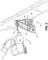
- FIG. 2 depicts a representation of a drilling system 100 during formation of a hole in a workpiece 102.
- the drilling system 100 includes the drilling apparatus 104 and the machine tool 106.
- the workpiece 102 includes a carrier 202 and a flap 204.
- the carrier 202 has a bottom flange 206 that contacts the flap 204 and a web 208 between the bottom flange 206 and a narrower top flange 210.
- a height from the bottom flange 206 to the top flange 210 varies up to a height of about 24 inches or more.
- the bottom flange 206 is coupled to the flap to form the workpiece 102 using one or more connecting devices (not shown).
- the connecting devices may include one or more clamps, one or more linkage systems, other devices, or combinations thereof.
- a number of holes are drilled in recesses on a first side of the web 208 through the bottom flange 206, through skin of the flap 204, and into support structure (not shown) of the flap 204 and a number of holes (e.g., four holes) are drilled in recesses on a second side of the web 208 through the bottom flange 206, through the skin of the flap 204, and into the support structure of the flap 204.
- the holes are close tolerance holes that cannot have a diameter below a minimum hole diameter (e.g., 0.500 inches, 0.625 inches, 0.750 inches or some other diameter) and can only exceed the minimum diameter by a small amount (e.g., 0.003 inches or some other tolerance threshold).
- the drilling system 100 is moved to another location, connectors are positioned in each of the holes to secure the carrier 202 to the flap 204, and the one or more connecting devices are removed.
- the drilling apparatus 104 includes a shaft 110, a tool 112 coupled to the shaft 110, an attachment box 114, an extension 116, a bearing housing 118, and an offset foot 120.
- the drilling apparatus 104 may include fewer components or additional components.
- the bearing housing 118 is directly coupled to the attachment box 114 without an extension 116 between the bearing housing 118 and the attachment box 114.
- the shaft 110 extends through the attachment box 114, the extension 116, and the bearing housing 118.
- the shaft 110 includes an end effector interface 302 (as shown in FIG. 3 ) at a first end of the shaft 110.
- the end effector interface 302 enables the shaft 110 to be releasably coupled to a particular end effector of end effectors 122 of the machine tool 106 so that the drilling apparatus 104 is able to perform a particular task.
- the particular end effector is a drill mechanism 124
- the end effector interface 302 is coupled to a spindle of the drill mechanism 124 of the machine tool 106.
- the end effector interface 302 is an HSK 40 spindle interface.
- the end effector interface 302 is another type of interface.
- the shaft 110 also includes a tool interface 126 at a second end of the shaft 110.
- the tool interface 126 includes a bore into the shaft 110 to receive an insertion portion of the tool 112, a set screw opening in a side of the shaft 110, and a first set screw 304 (e.g., as depicted in FIG. 3 ) positioned in the set screw opening to secure the insertion portion positioned in the bore to the shaft 110.
- a first set screw 304 e.g., as depicted in FIG. 3
- other tool interface configurations are used.
- the tool 112 is configured to perform one or more tasks.
- the tool 112 can be a touch probe to facilitate determination of a start location of a hole, a pen tool to mark a start location of the hole, a drill bit to form the hole, or another type of tool to perform one or more tasks.
- the tool 112 is releasably coupled to the tool interface 126.
- Some tools 112 may include an RFID (radio frequency identifier) collar 128 that includes an RFID chip 129.
- the RFID chip 129 stores information that identifies a particular tool, properties associated with the particular tool, or both.
- the drilling apparatus 104 sends an identifier signal received from the RFID chip 129 of the particular tool to the controller 108 of the machine tool 106.
- the identifier signal includes data that identifies the particular tool 112, a number of times the particular tool 112 has been used, other information, or combinations thereof.
- the controller 108 determines whether the particular tool 112 can be used (e.g., the number of uses of the tool 112 does not exceed a threshold number of uses when the tool 112 is a drill bit).
- the identifier signal or the lack of an identifier signal, enables the controller 108 to prevent inappropriate use of the tool 112 coupled to the tool interface 126 of the shaft 110.
- the controller 108 when the controller 108 does not receive the identifier signal associated with the tool 112 (e.g., the tool 112 is a touch probe that does not include an RFID collar 128) coupled to the shaft 110, the controller 108 is not able to send control instructions that would cause the machine tool 106 to use the drill mechanism 124 to rotate the tool 112 as if the tool 112 was a drill bit because the identifier signal does not indicate that the tool 112 is a drill bit.
- the controller 108 when the controller 108 does not receive the identifier signal associated with the tool 112 (e.g., the tool 112 is a touch probe that does not include an RFID collar 128) coupled to the shaft 110, the controller 108 is not able to send control instructions that would cause the machine tool 106 to use the drill mechanism 124 to rotate the tool 112 as if the tool 112 was a drill bit because the identifier signal does not indicate that the tool 112 is a drill bit.
- the insertion portion of the tool 112 includes a first flat portion.
- An end of the first set screw 304 (shown in FIG. 3 ) of the tool interface 126 is driven against the first flat portion when the tool 112 is securely coupled to the shaft 110.
- the tool 112, the tool interface 126, or both can include a visual marker to indicate a proper orientation of the tool 112 relative to the shaft 110 so that the first set screw 304 will contact the first flat portion when the first set screw 304 is driven against the tool insertion portion.
- the insertion portion includes a second flat portion to enable a second set screw 306 (shown in FIG.
- FIG. 4 depicts an implementation of a portion of a tool 112 with a first flat portion 402 and a second flat portion 404.
- the tool 112 depicted in FIG. 4 is a drill bit 406.
- the attachment box 114 is configured to couple the drilling apparatus 104 to the machine tool 106.
- the attachment box 114 may include one or more sets of positioning slots 308 that are configured to be placed on corresponding mounts of an end effector support platform of the tool arm 130 of the machine tool 106 when the drilling apparatus 104 is coupled to the machine tool 106.
- the attachment box 114 includes a set of positioning slots 308 (shown in FIG. 3 ) to orient the drilling apparatus 104 relative to the machine tool 106.
- the offset foot 120 is rotatable to two or more positions to accommodate use of the drilling apparatus 104 on a first side of structure of the workpiece 102 and a second side of the structure of the workpiece 102. Alternatively, work on the first side of the structure or the second side of the structure is accommodated by rotation, positioning, or both, of the tool arm 130 of the machine tool 106, the workpiece 102, or both.
- a sensor interface 132 of the attachment box 114 may be coupled to a corresponding sensor interface 134 of the machine tool 106 when the drilling apparatus 104 is coupled to the machine tool 106.
- the sensor interfaces 132, 134 may be quick release interfaces.
- the sensor interfaces 132, 134 complete a load cell that enables the controller 108 of the machine tool 106 to receive sensor signals that correspond to a force applied to the workpiece 102 by the machine tool 106 at a contact tip 136 of the offset foot 120.
- the sensor interfaces 132, 134, or other electrical connections between the drilling apparatus 104 and the machine tool 106 enable other sensor signals to be provided to the controller 108.
- the other sensor signals may include a signal corresponding to an applied torque between the workpiece 102 and the contact tip 136 of the offset foot 120, identification signals of the tool 112 coupled to the tool interface 126 of the shaft 110, position signals associated with an orientation of the offset foot 120, location signals from a touch probe coupled as the tool 112 to the tool interface 126 of the shaft 110, other sensor signals, or combinations thereof.
- the attachment box 114 may be releasably attached to the machine tool 106 by releasable latches of the machine tool 106 that engage latch mounts on a body of the attachment box 114 to secure the drilling apparatus 104 to the machine tool 106.
- the end effector interface 302 of the shaft 110 is configured to be coupled to a particular end effector of end effectors 122 of the machine tool 106.
- the end effector interface 302 is coupled to the spindle of the drill mechanism 124 of the end effectors 122 to enable the shaft 110 to rotate and move toward, or away from, the workpiece 102.
- the drilling system 100 may include one or more systems configured to prevent damage due to contact of a leg of the drilling apparatus 104 with an obstruction when the machine tool 106 moves the drilling apparatus 104 from a first location to a second location or during positioning of the drilling apparatus relative to the workpiece 102 via the tool arm 130.
- the leg of the drilling apparatus 104 includes the extension 116, the bearing housing 118, and the offset foot 120.
- the one or more systems include a camera system that provides image data of a work area associated with the machine tool 106 from two or more different perspectives to the controller 108.
- the controller 108 analyzes the image data and stops, or prevents, motion of the machine tool 106 when a person is in the work area, when a portion of the machine tool 106 or the drilling apparatus 104 is within a threshold distance of an object and continued motion of the machine tool 106 or the drilling apparatus 104 along a motion path would result in contact with the object, when other conditions are met, or combinations thereof.
- the attachment box 114 can include a detection system.
- the attachment box 114 includes a spring system 500 (shown in FIG. 5 ) to enable detection of external lateral forces that exceed a threshold force applied to the leg of the drilling apparatus 104.
- the shaft 110 is released from an end effector 122. Releasing the shaft 110 from the end effector 122 enables the first end of the shaft 110 to move should a lateral force be applied to the leg of the drilling apparatus 104.
- Lateral forces could be applied to the leg from an object (e.g., a person, a portion of the workpiece 102, a support structure for the workpiece 102, or other structure) when the machine tool 106 is moving the drilling apparatus 104 from a first location to another location.
- an object e.g., a person, a portion of the workpiece 102, a support structure for the workpiece 102, or other structure
- the extension 116 includes a flange 312 at a first end of the extension 116.
- the flange 312 is coupled to a plate 314 of the attachment box 114 by a plurality of spring and shoulder screw combinations (e.g., four spring and shoulder screw combinations).
- Each spring and shoulder screw combination includes a shoulder screw 316 with a threaded end that is threaded into the plate 314, a spring 318, and at least one end washer 320.
- the spring system 500 includes the flange 312, the plate 314, and the spring and shoulder screw combinations 316, 318, 320.
- the spring 318 of a spring and shoulder screw combination is a coil spring, a stack of appropriately oriented Belleville washers, or another type of biasing member. Strength of the springs 318 are selected to withstand a weight of the leg without sagging.
- a plurality of contact sensors 502 e.g., four contact sensors as depicted in FIG. 5 ) are coupled to the plate 314 and ends of the contact sensors 502 extend through the plate 314. When no external lateral force is applied to the leg, the springs 318 apply force to the flange 312 that presses the flange 312 against the ends of the contact sensors 502.
- a portion of the flange 312 presses against the plate 314 near one or more of the spring and bolt combinations and another portion of the flange 312 applies compressive force to the spring(s) 318 of one or more of the other spring and bolt combinations. If the compressive force is sufficiently large, a portion of the flange 312 will separate from the plate 314 and cause one or more of the contact sensors 502 to send an interrupt signal to the controller 108 of the machine tool 106 (shown in FIG. 1 ).
- the controller 108 In response to the interrupt signal, the controller 108 sends one or more control signals to components of the machine tool 106 that stop movement of the machine tool 106, movement of the tool arm 130 of the machine tool 106, or both, and provide an alert signal to an operator.
- the strengths of the springs 318 are selected so that the interrupt signal is provided when at least an activation force is applied near an end of the offset foot 120.
- the activation force may be 50 pounds force or some other amount of force near the end of the offset foot 120.
- the extension 116 includes the flange 312 at a first end and is coupled (e.g., welded or otherwise connected) to the bearing housing 118 at a second end.
- the extension 116 is used to set an offset length associated with the drilling apparatus 104.
- the offset length may be a longest orthogonal component of a distance from an end of the contact tip 136 of the offset foot 120 to a near edge of the attachment box 114.
- the offset length may be chosen based on a structure of a workpiece 102.
- the offset length may be 24.5 inches; if a largest orthogonal distance from a start location of a hole near structure of the workpiece 102 to a top of the structure is 16 inches, the offset length may be 16.5 inches; and if a largest orthogonal distance from a start location of a hole near structure of the workpiece 102 to a top of the structure is 14 inches, the offset length may be 14.3 inches. In other implementations, other offset distances may be implemented by use of an appropriately sized extension 116.
- the bearing housing 118 includes a pair of spaced apart bearings 138.
- the bearings 138 may be located near ends of the bearing housing 118.
- the bearings 138 are fluid bearings that support the shaft 110.
- the bearing housing 118 includes a pair of three inch long bearings 138 that abut ends of the bearing housing 118.
- Each bearing 138 includes a helical channel.
- a particular fluid line of fluid lines 140 supported by the offset foot 120 and coupled to fluid lines 142 of a fluid system 144 of the machine tool 106 supply lubrication fluid through a connector to a helical channel of a bearing 138.
- the offset foot 120 is coupled to the bearing housing 118 by one or more connectors.
- the offset foot 120 includes the contact tip 136 extending from a first end of the offset foot 120.
- the offset foot 120 houses a vacuum line 146 that aligns with a vacuum port of the contact tip 136.
- the vacuum line 146 extends to a second end of the offset foot 120.
- the vacuum line 146 is configured to couple to a flexible vacuum hose 148 of a vacuum system 150 of the machine tool 106. Cuttings produced during drilling of a hole are removed through the vacuum port in the contact tip 136 by a vacuum produced by the vacuum system 150.
- the offset foot 120 supports a plurality of fluid lines 140.
- One or more of the fluid lines 140 are used to supply lubricating fluid to the bearings 138.
- one or more of the fluid lines 140 may be used to supply a lubricating fluid, air, or both, through a plurality of fluid ports in the contact tip 136 to spray a mist of lubricating fluid on the tool 112 during formation of the hole to cool the tool 112 and facilitate removal of the cuttings.
- the offset foot 120 may also support one or more sensors .
- the sensors may include an RFID sensor 152 configured to read an RFID chip 129 coupled to the tool 112, to write to the RFID chip 129, or both.
- the controller 108 may write to the RFID chip 129 via the RFID sensor 152 to increase an indicator of the number of uses of the tool 112 after each use of the tool 112 to form a hole.
- the one or more sensors may also include one or more position sensors 154 configured to indicate an orientation of the offset foot 120 when the offset foot 120 is rotatable relative to the bearing housing 118 to accommodate operation of the drilling apparatus 104 on different sides of workpiece structure extending from a surface of the workpiece 102.
- the position sensors 154 provide one or more signals to the controller 108 that indicate whether the offset foot 120 is positioned for left side of structure drilling, right side of structure drilling, or center drilling.
- the offset foot 120 may include a spring connector 156 or other connection system that enables the offset foot 120 to be set at a particular orientation relative to the bearing housing 118.
- the spring connector 156 includes a spring in a body of the spring connector 156 that applies a force to a pin. The spring biases an end of the pin towards the bearing housing 118 when a grip of the spring connector is released. The end of the pin fits in an opening of the bearing housing 118 to lock the offset foot 120 in a particular orientation relative to the offset foot 120.
- the grip of the spring connector 156 is pulled to withdraw the pin from the opening, the offset foot 120 is rotated towards the desired orientation, the grip is released, and the offset foot 120 is further rotated towards the desired orientation until the spring pushes the pin into a second opening associated with the desired location.
- the offset foot 120 is not rotatable relative to the bearing housing 118.
- the contact tip 136 of the offset foot 120 includes the vacuum port and the plurality of fluid ports.
- the contact tip 136 includes a contact end that contacts a flat surface of the workpiece 102 to provide a large contact area between the contact end and the workpiece 102 to enable formation of holes normal to the flat surface of the workpiece 102 without slippage of the contact end relative to the workpiece 102 during formation of the hole.
- an interface 158 may be coupled to the contact end to provide a large contact area between the contact surface of the interface 158 and the flat surface of the workpiece 102 to allow the formation of a hole at a particular angle (e.g., at an angle above 0 degrees to 5 degrees) off of normal relative to the flat surface of the workpiece 102.
- the machine tool 106 controls positioning and operation of a device (e.g., the drilling apparatus 104) coupled to the machine tool 106.
- a device e.g., the drilling apparatus 104
- the machine tool 106 is a robot that includes the controller 108, a position drive 160, the tool arm 130 with one or more end effectors 122, a tool arm drive 162, the fluid system 144, and the vacuum system 150.
- the machine tool 106 includes fewer components or additional components.
- the machine tool 106 does not include a position drive 160 if the machine tool 106 is not configured to move from a fixed position.
- the controller 108 of the machine tool 106 is a computer system that provides control signals to components of the machine tool 106 to control operation of the machine tool 106.
- Use of the machine tool 106 may be manually controlled via the controller 108 based on user input or may be automatically controlled by the controller 108 based on sensor data received by the controller 108.
- the machine tool 106 may include the position drive 160.
- the position drive 160 moves the machine tool 106 from one location to another location so that the machine tool 106 is positioned in working relation to a stationary workpiece 102 based on command signals received from the controller 108.
- the machine tool 106 may be mounted to track rails, and the position drive 160 receives command signals from the controller 108 to position the machine tool 106 at a particular location along the track rails relative to the workpiece 102.
- the machine tool 106 may be stationary, and a workpiece 102 may be moved to a particular position in working relation to the machine tool 106.
- the machine tool 106 may also include the tool arm 130 and the tool arm drive 162.
- the tool arm drive 162 is configured to provide rotational positioning, location positioning, or both to a device (e.g., the drilling apparatus 104) coupled to the tool arm 130 based on command signals received from the controller 108.
- End effectors 122 of the tool arm 130 that are coupled to the device perform tasks on a workpiece 102 that is positioned in working relation to the machine tool 106 based on command signals received from the controller 108.
- the machine tool 106 includes one or more systems that facilitate performance of tasks by the machine tool 106.
- the machine tool 106 may include the fluid system 144 to provide fluid (e.g., a liquid or a gas) to a device (e.g., the drilling apparatus 104) via the one or more fluid lines 142, the vacuum system 150 to provide a vacuum via the vacuum hose 148 to a location near the workpiece 102, an electrical connection system 164 that includes sensor interfaces 134 to couple the controller 108 to the device in order for the controller 108 to receive sensor data from the device, and other systems.
- the fluid system 144 may include one or more pumps 166, pressure regulators, or other devices that control characteristics (e.g., temperature, pressure, quantity, etc.) of fluid provided to the device.
- FIG. 6 depicts a flowchart of an implementation of a process 600 of forming a hole in a workpiece using a drilling apparatus that enables formation of a close tolerance hole in a workpiece with restricted access to a start location of the hole, a large offset distance from the start location of the hole to an interface to a drive for the drilling apparatus, or both.
- the drilling apparatus may be the drilling apparatus 104 depicted in FIGS. 1-3 and the drive for the drilling apparatus may be the machine tool 106 depicted in FIG. 1 and FIG. 2 .
- the process 600 includes coupling the drilling apparatus 104 to the machine tool 106.
- Coupling the drilling apparatus 104 to the machine tool 1-6 may include moving positioning slots 308 of an attachment box 114 onto mounts of a tool arm 130 of the machine tool 106.
- the drilling apparatus 104 may be secured to the tool arm 130 by locking latches of the tool arm 130 to latch mounts of the attachment box 114.
- a vacuum hose 148 of the machine tool 106 may be coupled to a vacuum line 146 of the drilling apparatus 104 and appropriate fluid lines 142 of the machine tool 106 may be coupled to corresponding fluid lines 140 of the drilling apparatus 104.
- sensor interfaces 132 of the drilling apparatus 104 may be coupled to corresponding sensor interfaces of the machine tool 106.
- the process 600 may include, at block 604, determining a start location of a hole on a workpiece 102.
- the drilling apparatus 104 is moved by the machine tool 106 to a position in working relation to the workpiece 102 using a position drive 160, a tool arm drive 162, or both.
- the end effector interface 302 of the shaft 110 may be coupled to a particular effector of the end effectors 122 associated with use of a touch probe, and a touch probe may be attached as the tool 112 to the tool interface 126 of the shaft 110.
- the machine tool 106 may move the touch probe using the tool arm 130 and the particular effector to determine coordinate locations relative to the machine tool 106 of one or more surface features of the workpiece 102.
- a surface feature of the one or more surface features is a start hole at a location of the workpiece 102 where the hole is to be drilled.
- the start hole may have a smaller diameter than the hole to be drilled by the drilling apparatus 104.
- the one or more surface features include offset holes or other surface features of the workpiece 102 or a structure coupled to the workpiece.
- the controller 108 determines a coordinate location of the start hole and determines a contact location to position the contact tip 136 of the drilling apparatus 104 so that a center of the shaft 110 aligns with the coordinate location. After determining the locations of the one or more features, the drilling apparatus 104 is moved away from the workpiece 102 by the tool arm 130.
- the touch probe is removed from the shaft 110 and a pen tool is coupled to the tool interface 126 as the tool 112.
- the machine tool 106 may move the drilling apparatus 104 and contact the contact tip 136 using the tool arm 130 to the workpiece 102 at the contact location.
- the machine tool 106 may utilize the particular effector to mark the start location of the hole with ink or paint from the pen tool.
- the position of the drilling apparatus 104 is inspected to make sure that the drilling apparatus 104 only contacts the workpiece 102 at the contact tip 136.
- the drilling apparatus 104 is moved away from the workpiece 102 by the tool arm 130 and the mark is visually inspected by an operator to determine if the start location is at a proper location.
- the mark is removed and the touch probe is used again to determine one or more surface features, the operator can manually adjust the coordinate location of the start of the hole, the pen tool can be used to make another mark, or combinations thereof, until the mark is determined to be in a proper location.
- the machine tool 106 is used to move the drilling apparatus 104 away from the workpiece 102.
- the process 600 may also include, at block 606, drilling the hole in the workpiece 102.
- a drill bit is attached as the tool 112 to the tool interface 126 of the shaft 110 and the end effector interface 302 is coupled to the spindle of the drill mechanism 124 of the end effectors 122.
- the controller 108 sends command signals to return the contact tip 136 of the drilling apparatus 104 to the contact location.
- the controller 108 sends command signals to the machine tool to use the vacuum system 150 to draw a vacuum at a vacuum port of the contact tip 136 and sends command signals to the fluid system 144 to provide air and lubrication fluid to the fluid ports to supply a mist to the drill bit.
- the controller 108 also sends command signals to the machine tool to use the drill mechanism to form the hole in the workpiece.
- FIG. 7 is an illustration of a block diagram of a computing environment 700 including a computing device 702 configured to support implementations of computer-implemented methods and computer-executable program instructions (or code) according to the present disclosure.
- the computing device 702 or portions thereof, may execute instructions to perform, or cause equipment to perform, operations described with reference to FIGS. 1 and 6 .
- the computing device 702 is, or is a component of, the controller 108 of the machine tool 106 of FIG. 1 .
- the computing device 702 includes one or more processors 704.
- the processor(s) 704 communicate with a system memory 706, one or more storage devices 708, one or more input/output interfaces 710, one or more communications interfaces 712, or a combination thereof.
- the system memory 706 includes non-transitory computer readable media, including volatile memory devices (e.g., random access memory (RAM) devices), nonvolatile memory devices (e.g., read-only memory (ROM) devices, programmable read-only memory, and flash memory), or both.
- the system memory 706 includes an operating system 714, which may include a basic input/output system for booting the computing device 702 as well as a full operating system to enable the computing device 702 to interact with users, other programs, and other devices.
- the system memory 706 includes one or more applications 716 (e.g., instructions) which are executable by the processor(s) 704.
- the processor(s) 704 communicate with the one or more storage devices 708.
- the one or more storage devices 708 are non-transitory computer readable media that can include nonvolatile storage devices, such as magnetic disks, optical disks, or flash memory devices.
- the storage devices 708 can include both removable and non-removable memory devices.
- the storage devices 708 can be configured to store an operating system, images of operating systems, applications, and program data.
- the system memory 706, the storage devices 708, or both include tangible computer-readable media incorporated in hardware and which are not signals.
- the processor(s) 704 communicate with the one or more input/output interfaces 710 that enable the computing device 702 to communicate with one or more input/output devices 718 to facilitate user interaction.
- the input/output interfaces 710 can include serial interfaces (e.g., universal serial bus (USB) interfaces or Institute of Electrical and Electronics Engineers (IEEE) 1364 interfaces), parallel interfaces, display adapters, audio adapters, and other interfaces.
- the input/output devices 718 can include keyboards, pointing devices, displays (e.g., one or more monitors, one or more gauges, etc.), speakers, microphones, touch screens, rotatable selectors, levers, knobs, slides, switches, and other devices.
- the processor(s) 704 detect interaction events based on user input received via the input/output interfaces 710. Additionally, the processor(s) 704 send a display to a display device via the input/output interfaces 710.
- the processor(s) 704 can communicate with one or more devices 720 via the one or more communications interfaces 712.
- the one or more devices 720 can include external computing devices contacted via a communication network and controllers, sensors, and other devices coupled to the computing device 702 via wired or wireless local connections.
- the one or more communications interfaces 712 may include wired Ethernet interfaces, IEEE 802 wireless interfaces, other wireless communication interfaces, one or more converters to convert analog signals to digital signals, electrical signals to optical signals, one or more converters to convert received optical signals to electrical signals, or other network interfaces.
Landscapes
- Engineering & Computer Science (AREA)
- Mechanical Engineering (AREA)
- Robotics (AREA)
- General Engineering & Computer Science (AREA)
- Drilling And Boring (AREA)
Abstract
Description
- The present disclosure is related to a drilling apparatus and methods of use of the drilling apparatus. The drilling apparatus enables formation of a close tolerance hole at a location of a structure with limited access, a large offset distance from a drive mechanism for the drilling apparatus to a start location for the hole, or both.
- Machine tools are used during the manufacture of products. Some machine tools include a movable platform and a tool arm (e.g., a robot). Various tools can be attached to end effectors on the tool arm to perform particular tasks.
- During manufacture of some products (e.g., aircraft), holes need to be formed in workpieces at very precise locations and with very close tolerances. Close tolerance holes in relatively small workpieces that are easily moved are often formed using a drill press. For larger workpieces, a drill jig can be used to facilitate formation of close tolerance holes. For some workpieces, a location of the hole and a shape of the workpiece make the use of drill jigs labor intensive, time consuming, and unreliable to consistently produce holes within a tolerance limit due to deflection during drilling.
- According to one implementation of the present disclosure, a drilling apparatus includes an attachment box configured to couple to a machine tool. The drilling apparatus is configured to facilitate formation of a hole in a workpiece with workpiece structure that results in a large offset distance from a start location of the hole to the machine tool, restricted access to the start location of the hole, or both. The drilling apparatus includes a bearing housing coupled to the attachment box. The bearing housing includes a pair of bearings. The drilling apparatus includes a shaft position through the bearing housing to couple to the bearings of the bearing housing. The shaft includes an end effector interface configured to couple to one or more end effectors of the machine tool at a first end of the shaft. The shaft includes a tool interface configured to couple to a tool at a second end of the shaft. The drilling apparatus also includes an offset foot coupled to the bearing housing.
- According to another implementation of the present disclosure, a drilling system includes an attachment box to couple to an end effector of a machine tool. The drilling system is configured to facilitate formation of a hole in a workpiece with workpiece structure that results in a large offset distance from a start location of the hole to the end effector of the machine tool, restricted access to the start location of the hole, or both. The drilling system includes a bearing housing coupled to the attachment box. The bearing housing includes a pair of bearings. The drilling system includes a shaft positioned through the bearing housing to couple to the bearings of the bearing housing. The shaft is configured to couple to a spindle of the machine tool at a first end. The drilling system includes a drill bit configured to couple to a second end of the shaft. The drilling system also includes an offset foot coupled to the bearing housing. The offset foot includes a tip configured to contact the workpiece during use.
- According to another implementation of the present disclosure, a drilling system includes a machine tool. The machine tool includes a spindle. The drilling system is configured to facilitate formation of a hole in a workpiece with workpiece structure that results in a large offset distance from the machine tool to a start location of the hole, restricted access to the start location of the hole, or both. The drilling system includes an attachment box configured to couple to the machine tool. The drilling system includes a bearing housing coupled to the attachment box. The bearing housing includes a pair of bearings. The drilling system includes a shaft positioned through the bearing housing. The shaft is configured to couple to a drill mechanism of the machine tool at a first end of the shaft. The drilling system includes a drill bit configured to couple to a second end of the shaft. The drilling system also includes an offset foot coupled to the bearing housing. The offset foot includes a contact tip configured to contact the workpiece during use.
- The features, functions, and advantages that have been described can be achieved independently in various implementations or may be combined in yet other implementations, further details of which are disclosed with reference to the following description and drawings. The drawings are conceptual and not drawn to scale.
-
-
FIG. 1 is a block diagram of a drilling system. -
FIG. 2 is a perspective view of the drilling system ofFIG. 1 in use to form a hole in a workpiece. -
FIG. 3 is a perspective view of a drilling apparatus. -
FIG. 4 is a side view of a tool usable by the drilling apparatus ofFIG. 3 . -
FIG. 5 is a perspective view of a portion of the drilling apparatus ofFIG. 3 . -
FIG. 6 depicts a flowchart of a process of forming a hole in a workpiece using a drilling apparatus. -
FIG. 7 is a diagram of a representation of a computing device. - A drilling system enables a close tolerance hole to be drilled in a workpiece. The drilling system includes a machine tool that positions a drilling apparatus and utilizes the drilling apparatus to facilitate formation of the hole. The workpiece may include structure that results in a large offset distance from an end effector interface that couples to the machine tool to the start location of the hole. The structure may also result in limited access to the start location of the hole. During a process to form a close tolerance hole, a plurality of tools can be coupled to a tool interface of the drilling apparatus at various times during the process. In an implementation of forming the close tolerance hole, the tools can include a touch probe to determine surface features associated with the workpiece near a start location for the hole to facilitate determination of the start location of the hole, a pen tool to mark the start location where the hole will be formed, and a drill bit used to form the hole. In other implementations, fewer tools or additional tools can be coupled to the tool interface during the process of forming the close tolerance hole.
- The machine tool controls travel and a contact location of a contact tip of the drilling apparatus with the workpiece during the process of forming the close tolerance hole. An interface between the drilling apparatus and an effector of the machine tool that operates the drilling apparatus can be at a large offset distance from the location of the hole (e.g., 30 inches, 24 inches, or some other offset distance) to enable accommodation of workpiece structure near the location for the hole.
- The machine tool can control movement of the drilling apparatus (e.g., lateral movement relative to the workpiece and movement towards or away from the workpiece) such that placement of the contact tip of the drilling apparatus is at a particular location on the workpiece. When the contact tip of the drilling apparatus is at the particular location, a body of the drilling apparatus can be close to, but not contacting, the structure of the workpiece. For example, a separation distance between a portion of the structure of the workpiece and a body of the drilling apparatus can be about a sixteenth of an inch or greater for a workpiece where the hole is to be formed at a location with limited access to the location of the hole.
- The machine tool provides sufficient force to the drilling apparatus at the contact tip when the drilling apparatus is drilling the hole to counteract torque and drill thrust caused by interaction of the drill bit with the workpiece during formation of the hole and to consistently enable formation of holes that satisfy a tolerance threshold. A vacuum system of the machine tool coupled to the drilling apparatus removes cuttings during drilling. Also, a fluid system of the machine tool supplies fluid through fluid lines to the drilling apparatus to provide lubrication fluid to bearings of the drilling apparatus, to provide lubrication fluid as a mist to the drill bit to cool the drill bit and facilitate removal of cuttings by the vacuum system, or both.
- One technical benefit of the disclosed drilling apparatus is that drilling apparatus enables consistent formation of close tolerance holes in workpieces. A workpiece can include structure that results in a large offset distance from a start location of the hole to an interface between the drilling apparatus and a machine tool that drives the drilling apparatus, restricted access to the start location of the hole, or both. The formation of a close tolerance hole in the workpiece using the drilling system is more reliable to satisfy a tolerance threshold, quicker, and less human labor intensive than forming the hole using a drill jig. The drilling apparatus may be relatively light weight (e.g., less than 30 pounds). The light weight of the drilling apparatus and the maneuverability of the tool arm of the machine tool enable a single person, or two people, to couple the drilling apparatus to the machine tool or uncouple the drilling apparatus from the machine tool.
- Particular implementations are described herein with reference to the drawings. In the description, common features are designated by common reference numbers throughout the drawings. As used herein, various terminology is used for the purpose of describing particular implementations only and is not intended to be limiting. For example, the singular forms "a," "an," and "the" are intended to include the plural forms as well, unless the context clearly indicates otherwise. The terms "comprise," "comprises," and "comprising" are used interchangeably with "include," "includes," or "including." Additionally, the term "wherein" is used interchangeably with the term "where." As used herein, "exemplary" indicates an example, an implementation, and/or an aspect, and should not be construed as limiting or as indicating a preference or a preferred implementation. As used herein, an ordinal term (e.g., "first," "second," "third," etc.) used to modify an element, such as a structure, a component, an operation, etc., does not by itself indicate any priority, order, or arrangement of the element with respect to another element, but rather merely distinguishes the element from another element having a same name (but for use of the ordinal term). As used herein, the term "set" refers to a grouping of one or more elements, and the term "plurality" refers to multiple elements.
- As used herein, "generating," "calculating," "using," "selecting," "accessing," and "determining" are interchangeable unless context indicates otherwise. For example, "generating," "calculating," or "determining" a parameter (or a signal) can refer to actively generating, calculating, or determining the parameter (or the signal) or can refer to using, selecting, or accessing the parameter (or signal) that is already generated, such as by another component or device. As used herein, "coupled" can include "communicatively coupled," "electrically coupled," or "physically coupled," and can also (or alternatively) include any combinations thereof. Two devices (or components) can be coupled (e.g., communicatively coupled, electrically coupled, or physically coupled) directly or indirectly via one or more other devices, components, wires, buses, networks (e.g., a wired network, a wireless network, or a combination thereof), etc. Two devices (or components) that are electrically coupled can be included in the same device or in different devices and can be connected via electronics, one or more connectors, or inductive coupling, as illustrative, non-limiting examples. In some implementations, two devices (or components) that are communicatively coupled, such as in electrical communication, can send and receive electrical signals (digital signals or analog signals) directly or indirectly, such as via one or more wires, buses, networks, etc. As used herein, "directly coupled" is used to describe two devices that are coupled (e.g., communicatively coupled, electrically coupled, or physically coupled) without intervening components.
-
FIG. 1 is a block diagram of adrilling system 100 to facilitate formation of a hole in aworkpiece 102. Thedrilling system 100 includes adrilling apparatus 104 and amachine tool 106 configured to position and operate thedrilling apparatus 104. In some implementations, thedrilling apparatus 104 is used to perform several tasks associated with formation of the hole. For example, in particular implementations, thedrilling apparatus 104 is used to determine surface features associated with theworkpiece 102 near a location where the hole is to be formed, is used to mark a start location of the hole, is used to drill the hole, or combinations thereof. In other implementations, thedrilling apparatus 104 is used to perform fewer tasks or additional tasks. Determined surface features associated with theworkpiece 102 can include coordinate locations of features (e.g., holes, edges, slots, etc.) of theworkpiece 102 or supports for the workpiece 102 (e.g., linkage systems) for a coordinate system used by themachine tool 106. The determined surface features are used by acontroller 108 of themachine tool 106 to determine the start location of the hole. The start location may be at a particular surface feature or at an offset distance from one or more particular surface features. - In some usage implementations of the
drilling system 100, theworkpiece 102 does not include workpiece structure that inhibits access to a start location of a hole to be formed in theworkpiece 102. In other usage implementations of thedrilling system 100, theworkpiece 102 includes structure that can restrict access to a start location of a hole (e.g., the workpiece structure of theworkpiece 102 results in a large offset distance from a start location of a hole to an interface between thedrilling apparatus 104 and themachine tool 106, limited access to the start location, or both). - For example, during production of some types of aircraft, a carrier is attached to a flap of a wing to enable movement of the flap relative to other portions of the wing.
FIG. 2 depicts a representation of adrilling system 100 during formation of a hole in aworkpiece 102. Thedrilling system 100 includes thedrilling apparatus 104 and themachine tool 106. Theworkpiece 102 includes acarrier 202 and aflap 204. Thecarrier 202 has abottom flange 206 that contacts theflap 204 and aweb 208 between thebottom flange 206 and a narrowertop flange 210. A height from thebottom flange 206 to thetop flange 210 varies up to a height of about 24 inches or more. Web supports 212 coupled to theweb 208, thetop flange 210, and thebottom flange 206 create recesses in the carrier. The height of theweb 208 and limited accessibility to a location for the hole due to theweb 208, the web supports 212, thetop flange 210, the recesses, or combinations thereof, make securing thecarrier 202 to theflap 204 difficult. - To secure the
carrier 202 to theflap 204, thebottom flange 206 is coupled to the flap to form theworkpiece 102 using one or more connecting devices (not shown). The connecting devices may include one or more clamps, one or more linkage systems, other devices, or combinations thereof. Using thedrilling system 100, a number of holes (e.g., four holes) are drilled in recesses on a first side of theweb 208 through thebottom flange 206, through skin of theflap 204, and into support structure (not shown) of theflap 204 and a number of holes (e.g., four holes) are drilled in recesses on a second side of theweb 208 through thebottom flange 206, through the skin of theflap 204, and into the support structure of theflap 204. The holes are close tolerance holes that cannot have a diameter below a minimum hole diameter (e.g., 0.500 inches, 0.625 inches, 0.750 inches or some other diameter) and can only exceed the minimum diameter by a small amount (e.g., 0.003 inches or some other tolerance threshold). Thedrilling system 100 is moved to another location, connectors are positioned in each of the holes to secure thecarrier 202 to theflap 204, and the one or more connecting devices are removed. - As depicted in
FIG. 1 and inFIG. 3 , thedrilling apparatus 104 includes ashaft 110, atool 112 coupled to theshaft 110, anattachment box 114, anextension 116, a bearinghousing 118, and an offsetfoot 120. In other implementations, thedrilling apparatus 104 may include fewer components or additional components. For example, in an implementation, the bearinghousing 118 is directly coupled to theattachment box 114 without anextension 116 between the bearinghousing 118 and theattachment box 114. - The
shaft 110 extends through theattachment box 114, theextension 116, and the bearinghousing 118. Theshaft 110 includes an end effector interface 302 (as shown inFIG. 3 ) at a first end of theshaft 110. Theend effector interface 302 enables theshaft 110 to be releasably coupled to a particular end effector ofend effectors 122 of themachine tool 106 so that thedrilling apparatus 104 is able to perform a particular task. For example, when the task for thedrilling apparatus 104 is to drill a hole, the particular end effector is adrill mechanism 124, and theend effector interface 302 is coupled to a spindle of thedrill mechanism 124 of themachine tool 106. In an implementation, theend effector interface 302 is an HSK 40 spindle interface. In other implementations, theend effector interface 302 is another type of interface. - The
shaft 110 also includes atool interface 126 at a second end of theshaft 110. In a particular implementation, thetool interface 126 includes a bore into theshaft 110 to receive an insertion portion of thetool 112, a set screw opening in a side of theshaft 110, and a first set screw 304 (e.g., as depicted inFIG. 3 ) positioned in the set screw opening to secure the insertion portion positioned in the bore to theshaft 110. In other implementations, other tool interface configurations are used. - The
tool 112 is configured to perform one or more tasks. Thetool 112 can be a touch probe to facilitate determination of a start location of a hole, a pen tool to mark a start location of the hole, a drill bit to form the hole, or another type of tool to perform one or more tasks. - The
tool 112 is releasably coupled to thetool interface 126. Some tools 112 (e.g., drill bits) may include an RFID (radio frequency identifier)collar 128 that includes anRFID chip 129. TheRFID chip 129 stores information that identifies a particular tool, properties associated with the particular tool, or both. When the particular tool is coupled to theshaft 110, thedrilling apparatus 104 sends an identifier signal received from theRFID chip 129 of the particular tool to thecontroller 108 of themachine tool 106. The identifier signal includes data that identifies theparticular tool 112, a number of times theparticular tool 112 has been used, other information, or combinations thereof. Based on the data, thecontroller 108 determines whether theparticular tool 112 can be used (e.g., the number of uses of thetool 112 does not exceed a threshold number of uses when thetool 112 is a drill bit). The identifier signal, or the lack of an identifier signal, enables thecontroller 108 to prevent inappropriate use of thetool 112 coupled to thetool interface 126 of theshaft 110. For example, when thecontroller 108 does not receive the identifier signal associated with the tool 112 (e.g., thetool 112 is a touch probe that does not include an RFID collar 128) coupled to theshaft 110, thecontroller 108 is not able to send control instructions that would cause themachine tool 106 to use thedrill mechanism 124 to rotate thetool 112 as if thetool 112 was a drill bit because the identifier signal does not indicate that thetool 112 is a drill bit. - In some implementations, the insertion portion of the
tool 112 includes a first flat portion. An end of the first set screw 304 (shown inFIG. 3 ) of thetool interface 126 is driven against the first flat portion when thetool 112 is securely coupled to theshaft 110. Thetool 112, thetool interface 126, or both, can include a visual marker to indicate a proper orientation of thetool 112 relative to theshaft 110 so that thefirst set screw 304 will contact the first flat portion when thefirst set screw 304 is driven against the tool insertion portion. In implementations where thetool 112 includes anRFID collar 128, in addition to the first flat portion that enables the tool to be securely coupled to theshaft 110, the insertion portion includes a second flat portion to enable a second set screw 306 (shown inFIG. 3 ) to secure theRFID collar 128 to thetool 112.FIG. 4 depicts an implementation of a portion of atool 112 with a firstflat portion 402 and a secondflat portion 404. Thetool 112 depicted inFIG. 4 is adrill bit 406. - Returning to
FIG. 1 , theattachment box 114 is configured to couple thedrilling apparatus 104 to themachine tool 106. In some implementations, theattachment box 114 may include one or more sets of positioningslots 308 that are configured to be placed on corresponding mounts of an end effector support platform of thetool arm 130 of themachine tool 106 when thedrilling apparatus 104 is coupled to themachine tool 106. In an implementation, theattachment box 114 includes a set of positioning slots 308 (shown inFIG. 3 ) to orient thedrilling apparatus 104 relative to themachine tool 106. The offsetfoot 120 is rotatable to two or more positions to accommodate use of thedrilling apparatus 104 on a first side of structure of theworkpiece 102 and a second side of the structure of theworkpiece 102. Alternatively, work on the first side of the structure or the second side of the structure is accommodated by rotation, positioning, or both, of thetool arm 130 of themachine tool 106, theworkpiece 102, or both. - A
sensor interface 132 of theattachment box 114 may be coupled to acorresponding sensor interface 134 of themachine tool 106 when thedrilling apparatus 104 is coupled to themachine tool 106. The sensor interfaces 132, 134 may be quick release interfaces. The sensor interfaces 132, 134 complete a load cell that enables thecontroller 108 of themachine tool 106 to receive sensor signals that correspond to a force applied to theworkpiece 102 by themachine tool 106 at acontact tip 136 of the offsetfoot 120. In addition, the sensor interfaces 132, 134, or other electrical connections between thedrilling apparatus 104 and themachine tool 106, enable other sensor signals to be provided to thecontroller 108. The other sensor signals may include a signal corresponding to an applied torque between theworkpiece 102 and thecontact tip 136 of the offsetfoot 120, identification signals of thetool 112 coupled to thetool interface 126 of theshaft 110, position signals associated with an orientation of the offsetfoot 120, location signals from a touch probe coupled as thetool 112 to thetool interface 126 of theshaft 110, other sensor signals, or combinations thereof. - The
attachment box 114 may be releasably attached to themachine tool 106 by releasable latches of themachine tool 106 that engage latch mounts on a body of theattachment box 114 to secure thedrilling apparatus 104 to themachine tool 106. In addition, when theattachment box 114 is coupled to themachine tool 106, theend effector interface 302 of theshaft 110 is configured to be coupled to a particular end effector ofend effectors 122 of themachine tool 106. For example, when thedrilling apparatus 104 is to be used to drill a hole in theworkpiece 102, theend effector interface 302 is coupled to the spindle of thedrill mechanism 124 of theend effectors 122 to enable theshaft 110 to rotate and move toward, or away from, theworkpiece 102. - The
drilling system 100 may include one or more systems configured to prevent damage due to contact of a leg of thedrilling apparatus 104 with an obstruction when themachine tool 106 moves thedrilling apparatus 104 from a first location to a second location or during positioning of the drilling apparatus relative to theworkpiece 102 via thetool arm 130. The leg of thedrilling apparatus 104 includes theextension 116, the bearinghousing 118, and the offsetfoot 120. - In an implementation, the one or more systems include a camera system that provides image data of a work area associated with the
machine tool 106 from two or more different perspectives to thecontroller 108. Thecontroller 108 analyzes the image data and stops, or prevents, motion of themachine tool 106 when a person is in the work area, when a portion of themachine tool 106 or thedrilling apparatus 104 is within a threshold distance of an object and continued motion of themachine tool 106 or thedrilling apparatus 104 along a motion path would result in contact with the object, when other conditions are met, or combinations thereof. - Alternatively or in addition, the
attachment box 114 can include a detection system. In an implementation, theattachment box 114 includes a spring system 500 (shown inFIG. 5 ) to enable detection of external lateral forces that exceed a threshold force applied to the leg of thedrilling apparatus 104. When themachine tool 106 is used to move thedrilling apparatus 104 from a first location to a second location, theshaft 110 is released from anend effector 122. Releasing theshaft 110 from theend effector 122 enables the first end of theshaft 110 to move should a lateral force be applied to the leg of thedrilling apparatus 104. Lateral forces could be applied to the leg from an object (e.g., a person, a portion of theworkpiece 102, a support structure for theworkpiece 102, or other structure) when themachine tool 106 is moving thedrilling apparatus 104 from a first location to another location. - As depicted in
FIG. 3 and inFIG. 5 , theextension 116 includes aflange 312 at a first end of theextension 116. Theflange 312 is coupled to aplate 314 of theattachment box 114 by a plurality of spring and shoulder screw combinations (e.g., four spring and shoulder screw combinations). Each spring and shoulder screw combination includes ashoulder screw 316 with a threaded end that is threaded into theplate 314, aspring 318, and at least oneend washer 320. Thespring system 500 includes theflange 312, theplate 314, and the spring andshoulder screw combinations spring 318 of a spring and shoulder screw combination is a coil spring, a stack of appropriately oriented Belleville washers, or another type of biasing member. Strength of thesprings 318 are selected to withstand a weight of the leg without sagging. A plurality of contact sensors 502 (e.g., four contact sensors as depicted inFIG. 5 ) are coupled to theplate 314 and ends of thecontact sensors 502 extend through theplate 314. When no external lateral force is applied to the leg, thesprings 318 apply force to theflange 312 that presses theflange 312 against the ends of thecontact sensors 502. - When an external lateral force is applied to the leg, a portion of the
flange 312 presses against theplate 314 near one or more of the spring and bolt combinations and another portion of theflange 312 applies compressive force to the spring(s) 318 of one or more of the other spring and bolt combinations. If the compressive force is sufficiently large, a portion of theflange 312 will separate from theplate 314 and cause one or more of thecontact sensors 502 to send an interrupt signal to thecontroller 108 of the machine tool 106 (shown inFIG. 1 ). In response to the interrupt signal, thecontroller 108 sends one or more control signals to components of themachine tool 106 that stop movement of themachine tool 106, movement of thetool arm 130 of themachine tool 106, or both, and provide an alert signal to an operator. The strengths of thesprings 318 are selected so that the interrupt signal is provided when at least an activation force is applied near an end of the offsetfoot 120. The activation force may be 50 pounds force or some other amount of force near the end of the offsetfoot 120. - The
extension 116 includes theflange 312 at a first end and is coupled (e.g., welded or otherwise connected) to the bearinghousing 118 at a second end. Theextension 116 is used to set an offset length associated with thedrilling apparatus 104. The offset length may be a longest orthogonal component of a distance from an end of thecontact tip 136 of the offsetfoot 120 to a near edge of theattachment box 114. The offset length may be chosen based on a structure of aworkpiece 102. As non-limiting examples, if a largest orthogonal distance from a start location of a hole near structure of theworkpiece 102 to a top of the structure is 24 inches, the offset length may be 24.5 inches; if a largest orthogonal distance from a start location of a hole near structure of theworkpiece 102 to a top of the structure is 16 inches, the offset length may be 16.5 inches; and if a largest orthogonal distance from a start location of a hole near structure of theworkpiece 102 to a top of the structure is 14 inches, the offset length may be 14.3 inches. In other implementations, other offset distances may be implemented by use of an appropriatelysized extension 116. - The bearing
housing 118 includes a pair of spaced apartbearings 138. Thebearings 138 may be located near ends of the bearinghousing 118. In some implementations, thebearings 138 are fluid bearings that support theshaft 110. In an implementation, the bearinghousing 118 includes a pair of three inchlong bearings 138 that abut ends of the bearinghousing 118. Each bearing 138 includes a helical channel. A particular fluid line offluid lines 140 supported by the offsetfoot 120 and coupled tofluid lines 142 of afluid system 144 of themachine tool 106 supply lubrication fluid through a connector to a helical channel of abearing 138. - The offset
foot 120 is coupled to the bearinghousing 118 by one or more connectors. The offsetfoot 120 includes thecontact tip 136 extending from a first end of the offsetfoot 120. The offsetfoot 120 houses avacuum line 146 that aligns with a vacuum port of thecontact tip 136. Thevacuum line 146 extends to a second end of the offsetfoot 120. At the second end of the offsetfoot 120, thevacuum line 146 is configured to couple to aflexible vacuum hose 148 of avacuum system 150 of themachine tool 106. Cuttings produced during drilling of a hole are removed through the vacuum port in thecontact tip 136 by a vacuum produced by thevacuum system 150. - The offset
foot 120 supports a plurality offluid lines 140. One or more of thefluid lines 140 are used to supply lubricating fluid to thebearings 138. Also, one or more of thefluid lines 140 may be used to supply a lubricating fluid, air, or both, through a plurality of fluid ports in thecontact tip 136 to spray a mist of lubricating fluid on thetool 112 during formation of the hole to cool thetool 112 and facilitate removal of the cuttings. - The offset
foot 120 may also support one or more sensors . The sensors may include anRFID sensor 152 configured to read anRFID chip 129 coupled to thetool 112, to write to theRFID chip 129, or both. When thetool 112 is a drill bit, thecontroller 108 may write to theRFID chip 129 via theRFID sensor 152 to increase an indicator of the number of uses of thetool 112 after each use of thetool 112 to form a hole. - The one or more sensors may also include one or
more position sensors 154 configured to indicate an orientation of the offsetfoot 120 when the offsetfoot 120 is rotatable relative to the bearinghousing 118 to accommodate operation of thedrilling apparatus 104 on different sides of workpiece structure extending from a surface of theworkpiece 102. In a particular implementation, theposition sensors 154 provide one or more signals to thecontroller 108 that indicate whether the offsetfoot 120 is positioned for left side of structure drilling, right side of structure drilling, or center drilling. - In implementations where the offset
foot 120 is rotatable about a longitudinal axis of the bearinghousing 118, the offsetfoot 120 may include aspring connector 156 or other connection system that enables the offsetfoot 120 to be set at a particular orientation relative to the bearinghousing 118. Thespring connector 156 includes a spring in a body of thespring connector 156 that applies a force to a pin. The spring biases an end of the pin towards the bearinghousing 118 when a grip of the spring connector is released. The end of the pin fits in an opening of the bearinghousing 118 to lock the offsetfoot 120 in a particular orientation relative to the offsetfoot 120. When a different orientation is desired, the grip of thespring connector 156 is pulled to withdraw the pin from the opening, the offsetfoot 120 is rotated towards the desired orientation, the grip is released, and the offsetfoot 120 is further rotated towards the desired orientation until the spring pushes the pin into a second opening associated with the desired location. In other implementations, the offsetfoot 120 is not rotatable relative to the bearinghousing 118. - The
contact tip 136 of the offsetfoot 120 includes the vacuum port and the plurality of fluid ports. Thecontact tip 136 includes a contact end that contacts a flat surface of theworkpiece 102 to provide a large contact area between the contact end and theworkpiece 102 to enable formation of holes normal to the flat surface of theworkpiece 102 without slippage of the contact end relative to theworkpiece 102 during formation of the hole. In some implementations, aninterface 158 may be coupled to the contact end to provide a large contact area between the contact surface of theinterface 158 and the flat surface of theworkpiece 102 to allow the formation of a hole at a particular angle (e.g., at an angle above 0 degrees to 5 degrees) off of normal relative to the flat surface of theworkpiece 102. - The
machine tool 106 controls positioning and operation of a device (e.g., the drilling apparatus 104) coupled to themachine tool 106. In the implementation depicted inFIG. 1 , themachine tool 106 is a robot that includes thecontroller 108, aposition drive 160, thetool arm 130 with one ormore end effectors 122, atool arm drive 162, thefluid system 144, and thevacuum system 150. In other implementations, themachine tool 106 includes fewer components or additional components. For example, themachine tool 106 does not include aposition drive 160 if themachine tool 106 is not configured to move from a fixed position. - The
controller 108 of themachine tool 106 is a computer system that provides control signals to components of themachine tool 106 to control operation of themachine tool 106. Use of themachine tool 106 may be manually controlled via thecontroller 108 based on user input or may be automatically controlled by thecontroller 108 based on sensor data received by thecontroller 108. - The
machine tool 106 may include the position drive 160. The position drive 160 moves themachine tool 106 from one location to another location so that themachine tool 106 is positioned in working relation to astationary workpiece 102 based on command signals received from thecontroller 108. For example, themachine tool 106 may be mounted to track rails, and the position drive 160 receives command signals from thecontroller 108 to position themachine tool 106 at a particular location along the track rails relative to theworkpiece 102. In other implementations, themachine tool 106 may be stationary, and aworkpiece 102 may be moved to a particular position in working relation to themachine tool 106. - The
machine tool 106 may also include thetool arm 130 and thetool arm drive 162. Thetool arm drive 162 is configured to provide rotational positioning, location positioning, or both to a device (e.g., the drilling apparatus 104) coupled to thetool arm 130 based on command signals received from thecontroller 108.End effectors 122 of thetool arm 130 that are coupled to the device perform tasks on aworkpiece 102 that is positioned in working relation to themachine tool 106 based on command signals received from thecontroller 108. - The
machine tool 106 includes one or more systems that facilitate performance of tasks by themachine tool 106. For example, themachine tool 106 may include thefluid system 144 to provide fluid (e.g., a liquid or a gas) to a device (e.g., the drilling apparatus 104) via the one or morefluid lines 142, thevacuum system 150 to provide a vacuum via thevacuum hose 148 to a location near theworkpiece 102, anelectrical connection system 164 that includessensor interfaces 134 to couple thecontroller 108 to the device in order for thecontroller 108 to receive sensor data from the device, and other systems. Thefluid system 144 may include one ormore pumps 166, pressure regulators, or other devices that control characteristics (e.g., temperature, pressure, quantity, etc.) of fluid provided to the device. -
FIG. 6 depicts a flowchart of an implementation of aprocess 600 of forming a hole in a workpiece using a drilling apparatus that enables formation of a close tolerance hole in a workpiece with restricted access to a start location of the hole, a large offset distance from the start location of the hole to an interface to a drive for the drilling apparatus, or both. The drilling apparatus may be thedrilling apparatus 104 depicted inFIGS. 1-3 and the drive for the drilling apparatus may be themachine tool 106 depicted inFIG. 1 andFIG. 2 . - The
process 600, atblock 602, includes coupling thedrilling apparatus 104 to themachine tool 106. Coupling thedrilling apparatus 104 to the machine tool 1-6 may include movingpositioning slots 308 of anattachment box 114 onto mounts of atool arm 130 of themachine tool 106. Thedrilling apparatus 104 may be secured to thetool arm 130 by locking latches of thetool arm 130 to latch mounts of theattachment box 114. Avacuum hose 148 of themachine tool 106 may be coupled to avacuum line 146 of thedrilling apparatus 104 andappropriate fluid lines 142 of themachine tool 106 may be coupled to correspondingfluid lines 140 of thedrilling apparatus 104. Also, sensor interfaces 132 of thedrilling apparatus 104 may be coupled to corresponding sensor interfaces of themachine tool 106. - The
process 600 may include, atblock 604, determining a start location of a hole on aworkpiece 102. To determine the start location of the hole, thedrilling apparatus 104 is moved by themachine tool 106 to a position in working relation to theworkpiece 102 using aposition drive 160, atool arm drive 162, or both. Theend effector interface 302 of theshaft 110 may be coupled to a particular effector of theend effectors 122 associated with use of a touch probe, and a touch probe may be attached as thetool 112 to thetool interface 126 of theshaft 110. - The
machine tool 106 may move the touch probe using thetool arm 130 and the particular effector to determine coordinate locations relative to themachine tool 106 of one or more surface features of theworkpiece 102. In some implementations, a surface feature of the one or more surface features is a start hole at a location of theworkpiece 102 where the hole is to be drilled. The start hole may have a smaller diameter than the hole to be drilled by thedrilling apparatus 104. In other implementations, the one or more surface features include offset holes or other surface features of theworkpiece 102 or a structure coupled to the workpiece. Based on locations of the one or more surface features determined by use of the touch probe, thecontroller 108 determines a coordinate location of the start hole and determines a contact location to position thecontact tip 136 of thedrilling apparatus 104 so that a center of theshaft 110 aligns with the coordinate location. After determining the locations of the one or more features, thedrilling apparatus 104 is moved away from theworkpiece 102 by thetool arm 130. - In some implementations, the touch probe is removed from the
shaft 110 and a pen tool is coupled to thetool interface 126 as thetool 112. Themachine tool 106 may move thedrilling apparatus 104 and contact thecontact tip 136 using thetool arm 130 to theworkpiece 102 at the contact location. Themachine tool 106 may utilize the particular effector to mark the start location of the hole with ink or paint from the pen tool. The position of thedrilling apparatus 104 is inspected to make sure that thedrilling apparatus 104 only contacts theworkpiece 102 at thecontact tip 136. Thedrilling apparatus 104 is moved away from theworkpiece 102 by thetool arm 130 and the mark is visually inspected by an operator to determine if the start location is at a proper location. If the mark is not at the proper location, the mark is removed and the touch probe is used again to determine one or more surface features, the operator can manually adjust the coordinate location of the start of the hole, the pen tool can be used to make another mark, or combinations thereof, until the mark is determined to be in a proper location. When the operator determines that the mark is at the proper location, themachine tool 106 is used to move thedrilling apparatus 104 away from theworkpiece 102. - The
process 600 may also include, atblock 606, drilling the hole in theworkpiece 102. To drill the hole in theworkpiece 102, a drill bit is attached as thetool 112 to thetool interface 126 of theshaft 110 and theend effector interface 302 is coupled to the spindle of thedrill mechanism 124 of theend effectors 122. Thecontroller 108 sends command signals to return thecontact tip 136 of thedrilling apparatus 104 to the contact location. Thecontroller 108 sends command signals to the machine tool to use thevacuum system 150 to draw a vacuum at a vacuum port of thecontact tip 136 and sends command signals to thefluid system 144 to provide air and lubrication fluid to the fluid ports to supply a mist to the drill bit. Thecontroller 108 also sends command signals to the machine tool to use the drill mechanism to form the hole in the workpiece. -
FIG. 7 is an illustration of a block diagram of acomputing environment 700 including acomputing device 702 configured to support implementations of computer-implemented methods and computer-executable program instructions (or code) according to the present disclosure. For example, thecomputing device 702, or portions thereof, may execute instructions to perform, or cause equipment to perform, operations described with reference toFIGS. 1 and6 . In an implementation, thecomputing device 702 is, or is a component of, thecontroller 108 of themachine tool 106 ofFIG. 1 . - The
computing device 702 includes one ormore processors 704. The processor(s) 704 communicate with asystem memory 706, one ormore storage devices 708, one or more input/output interfaces 710, one ormore communications interfaces 712, or a combination thereof. Thesystem memory 706 includes non-transitory computer readable media, including volatile memory devices (e.g., random access memory (RAM) devices), nonvolatile memory devices (e.g., read-only memory (ROM) devices, programmable read-only memory, and flash memory), or both. Thesystem memory 706 includes anoperating system 714, which may include a basic input/output system for booting thecomputing device 702 as well as a full operating system to enable thecomputing device 702 to interact with users, other programs, and other devices. Thesystem memory 706 includes one or more applications 716 (e.g., instructions) which are executable by the processor(s) 704. - The processor(s) 704 communicate with the one or
more storage devices 708. For example, the one ormore storage devices 708 are non-transitory computer readable media that can include nonvolatile storage devices, such as magnetic disks, optical disks, or flash memory devices. Thestorage devices 708 can include both removable and non-removable memory devices. Thestorage devices 708 can be configured to store an operating system, images of operating systems, applications, and program data. In particular implementations, thesystem memory 706, thestorage devices 708, or both, include tangible computer-readable media incorporated in hardware and which are not signals. - The processor(s) 704 communicate with the one or more input/
output interfaces 710 that enable thecomputing device 702 to communicate with one or more input/output devices 718 to facilitate user interaction. The input/output interfaces 710 can include serial interfaces (e.g., universal serial bus (USB) interfaces or Institute of Electrical and Electronics Engineers (IEEE) 1364 interfaces), parallel interfaces, display adapters, audio adapters, and other interfaces. The input/output devices 718 can include keyboards, pointing devices, displays (e.g., one or more monitors, one or more gauges, etc.), speakers, microphones, touch screens, rotatable selectors, levers, knobs, slides, switches, and other devices. The processor(s) 704 detect interaction events based on user input received via the input/output interfaces 710. Additionally, the processor(s) 704 send a display to a display device via the input/output interfaces 710. - The processor(s) 704 can communicate with one or
more devices 720 via the one or more communications interfaces 712. The one ormore devices 720 can include external computing devices contacted via a communication network and controllers, sensors, and other devices coupled to thecomputing device 702 via wired or wireless local connections. The one ormore communications interfaces 712 may include wired Ethernet interfaces, IEEE 802 wireless interfaces, other wireless communication interfaces, one or more converters to convert analog signals to digital signals, electrical signals to optical signals, one or more converters to convert received optical signals to electrical signals, or other network interfaces. - Aspects of the disclosure are described further with reference to the following set of interrelated clauses:
- According to Clause 1, a drilling apparatus to facilitate formation of a hole in a workpiece with workpiece structure that results in a large offset distance from a start location of the hole to a machine tool, restricted access to the start location of the hole, or both, includes: an attachment box configured to couple to a machine tool; a bearing housing coupled to the attachment box, wherein the bearing housing includes a pair of bearings; a shaft positioned through the bearing housing to couple to the bearings of the bearing housing, wherein the shaft includes an end effector interface configured to couple to one or more end effectors of the machine tool at a first end of the shaft, and wherein the shaft includes a tool interface configured to couple to a tool at a second end of the shaft; and an offset foot coupled to the bearing housing.
- Clause 2 includes the drilling apparatus of Clause 1, and further includes an extension positioned between the attachment box and the bearing housing.
- Clause 3 includes the drilling apparatus of Clause 1 or Clause 2, wherein the attachment box includes sensors and a spring system configured to detect deflection of the bearing housing relative to the attachment box.
- Clause 4 includes the drilling apparatus of any of Clauses 1 to 3, wherein the machine tool is a robot and wherein the attachment box is coupled to a tool arm of the robot.
- Clause 5 includes the drilling apparatus of any of Clauses 1 to 4, wherein the tool includes one of a drill bit, a touch probe, and a marking pen.
- Clause 6 includes the drilling apparatus of any of Clauses 1 to 5, wherein the offset foot is configured to attach to a first fluid line to provide a lubricant to the bearings of the bearing housing during use.
- Clause 7 includes the drilling apparatus of any of Clauses 1 to 6, wherein the tool comprises a drill bit, and wherein the offset foot is configured to couple to a vacuum hose that removes cuttings produced by the drill bit from the workpiece during use.
- Clause 8 includes the drilling apparatus of any of Clauses 1 to 7, wherein the tool comprises a drill bit, and wherein the offset foot is configured to attach to one or more fluid lines to provide a mist of lubrication fluid to the drill bit during use of the drill bit to form a hole in the workpiece.
- Clause 9 includes the drilling apparatus of any of Clauses 1 to 8, wherein the offset foot is rotatable about a longitudinal axis of the bearing housing, and wherein the offset foot is configured to lock in place at two or more distinct positions relative to the bearing housing.
- Clause 10 includes the drilling apparatus of Clause 9, wherein the offset foot includes a position sensor to detect a position of the offset foot relative to the bearing housing.
- According to Clause 11, a drilling system configured to facilitate formation of a hole in a workpiece with workpiece structure that results in a large offset distance from a start location of the hole to a machine tool, restricted access to the start location of the hole, or both, includes: an attachment box to couple to a machine tool; a bearing housing coupled to the attachment box, wherein the bearing housing includes a pair of bearings; a shaft positioned through the bearing housing to couple to the bearings, wherein the shaft is configured to couple to a drill mechanism of the machine tool at a first end; a drill bit configured to couple a second end of the shaft; and an offset foot coupled to the bearing housing, wherein a contact tip of the offset foot is configured to contact a workpiece during use.
- Clause 12 includes the drilling system of Clause 11, and further includes a collar coupled to the drill bit, the collar including a radio frequency identifier (RFID) chip with data that identifies the drill bit.
- Clause 13 includes the drilling system of Clause 12, wherein the offset foot further comprises a RFID sensor to provide an identifier of the drill bit received from the RFID chip to a controller of the machine tool.
- Clause 14 includes the drilling system of any of Clause 11 to 13, and further includes an extension tube positioned between the attachment box and the bearing housing.
- Clause 15 includes the drilling system of any of Clause 11 to 14, and further includes an interface configured to couple to the contact tip, wherein the interface enables formation of a hole in the workpiece at an angle relative to a normal direction of a surface of the workpiece contacted by the interface, and wherein the angle is greater than 0 degrees and less than five degrees.
- According to Clause 16, a drill system configured to facilitate formation of a hole in a workpiece with workpiece structure that results in a large offset distance from a start location of the hole to a machine tool, restricted access to the start location of the hole, or both, includes: the machine tool; an attachment box configured to couple to the machine tool; a bearing housing coupled to the attachment box, wherein the bearing housing includes a pair of bearings; a shaft positioned through the bearing housing, wherein the shaft is configured to couple to a spindle of the machine tool at a first end of the shaft; a drill bit configured to couple to a second end of the shaft; and an offset foot coupled to the bearing housing, wherein a contact tip of the offset is configured to contact a workpiece during use.
- Clause 17 includes the drilling system of Clause 16, and further includes a fluid pump to provide lubrication to the bearings of the bearing housing.
- Clause 18 includes the drilling system of Clause 16 or Clause 17, and further includes a vacuum system coupled to the offset foot by a hose.
- Clause 19 includes the drilling system of any of Clauses 16 to 18, wherein the attachment box includes sensors and a spring system configured to detect deflection of the bearing housing relative to the attachment box.
- Clause 20 includes the drilling system of any of Clauses 16 to 19, wherein the offset foot is rotatable about a longitudinal axis of the bearing housing, and wherein the offset foot is configured to lock in place at two or more distinct positions relative to the bearing housing.
- Clause 21 includes the drilling system of Clause 20, further including one or more position sensors to provide position data to the machine tool, wherein the position data indicates an orientation of the offset foot.
- The Abstract of the Disclosure is submitted with the understanding that it will not be used to interpret or limit the scope or meaning of the claims. In addition, in the foregoing Detailed Description, various features may be grouped together or described in a single implementation for the purpose of streamlining the disclosure. Examples described above illustrate but do not limit the disclosure. It should also be understood that numerous modifications and variations are possible in accordance with the principles of the present disclosure. As the following claims reflect, the claimed subject matter may be directed to less than all of the features of any of the disclosed examples. Accordingly, the scope of the disclosure is defined by the following claims and their equivalents.
Claims (15)
- A drilling apparatus (104) configured to facilitate formation of a hole in a workpiece (102) with workpiece structure that results in a large offset distance from a start location of the hole to a machine tool (106), restricted access to the start location of the hole, or both, the drilling apparatus comprising:an attachment box (114) configured to couple to a machine tool;a bearing housing (118) coupled to the attachment box, wherein the bearing housing includes a pair of bearings;a shaft (110) positioned through the bearing housing to couple to the bearings of the bearing housing, wherein the shaft includes an end effector interface (302) configured to couple to one or more end effectors of the machine tool at a first end of the shaft, and wherein the shaft includes a tool interface (126) configured to couple to a tool (112) at a second end of the shaft; andan offset foot (120) coupled to the bearing housing.
- The drilling apparatus of claim 1, further comprising an extension (116) positioned between the attachment box and the bearing housing.
- The drilling apparatus of claim 1 or 2, wherein the attachment box includes sensors and a spring system (500) configured to detect deflection of the bearing housing relative to the attachment box.
- The drilling apparatus of any one of claims 1 to 3, wherein the machine tool is a robot and wherein the attachment box is coupled to a tool arm (130) of the robot.
- The drilling apparatus of any one of claims 1 to 4, wherein the tool includes one of a drill bit (406), a touch probe, and a pen tool.
- The drilling apparatus of any one of claims 1 to 5, wherein the offset foot is configured to attach to a first fluid line (140) to provide a lubricant to the bearings of the bearing housing during use.
- The drilling apparatus of any one of claims 1 to 6, wherein the tool comprises a drill bit (406), and wherein the offset foot is configured to couple to a vacuum hose (148) that removes cuttings produced by the drill bit from the workpiece during use.
- The drilling apparatus of any one of claims 1 to 7, wherein the tool comprises a drill bit (406), and wherein the offset foot is configured to attach to one or more fluid lines (140) to provide a mist of lubrication fluid to the drill bit during use of the drill bit to form a hole in the workpiece.
- The drilling apparatus of any one of claims 1 to 8, wherein the offset foot is rotatable about a longitudinal axis of the bearing housing, and wherein the offset foot is configured to lock in place at two or more distinct positions relative to the bearing housing.
- The drilling apparatus of claim 9, wherein the offset foot includes a position sensor (154) to detect a position of the offset foot relative to the bearing housing.
- A drilling system (100) configured to facilitate formation of a hole in a workpiece with workpiece (102) structure that results in a large offset distance from a start location of the hole to a machine tool (106), restricted access to the start location of the hole, or both, the drilling system comprising:
the machine tool and a drilling apparatus (104), wherein the drilling apparatus comprises:an attachment box (114) configured to couple to the machine tool;a bearing housing (118) coupled to the attachment box, wherein the bearing housing includes a pair of bearings;a shaft (110) positioned through the bearing housing to couple to the bearings, wherein the shaft is configured to couple to a drill mechanism (124) of the machine tool at a first end;a drill bit (406) configured to couple a second end of the shaft; andan offset foot (120) coupled to the bearing housing, wherein a contact tip (136) of the offset foot is configured to contact the workpiece during use. - The drilling system of claim 11, further comprising a collar (128) coupled to the drill bit, the collar including a radio frequency identifier (RFID) chip (129) with data that identifies the drill bit.
- The drilling system of claim 12, wherein the offset foot further comprises a RFID sensor (152) to provide an identifier of the drill bit received from the RFID chip (129) to a controller (108) of the machine tool.
- The drilling system of any one of claims 11 to 13, further comprising an extension (116) positioned between the attachment box and the bearing housing.
- The drilling system of any one of claims 11 to 14, further comprising an interface configured to couple to the contact tip, wherein the interface enables formation of a hole in the workpiece at an angle relative to a normal direction of a surface of the workpiece contacted by the interface, and wherein the angle is greater than 0 degrees and less than five degrees.
Applications Claiming Priority (1)
| Application Number | Priority Date | Filing Date | Title |
|---|---|---|---|
| US18/154,656 US20240238878A1 (en) | 2023-01-13 | 2023-01-13 | Drilling apparatus |
Publications (2)
| Publication Number | Publication Date |
|---|---|
| EP4400238A2 true EP4400238A2 (en) | 2024-07-17 |
| EP4400238A3 EP4400238A3 (en) | 2024-10-09 |
Family
ID=88647524
Family Applications (1)
| Application Number | Title | Priority Date | Filing Date |
|---|---|---|---|
| EP23206918.7A Pending EP4400238A3 (en) | 2023-01-13 | 2023-10-31 | Drilling apparatus and drilling system |
Country Status (2)
| Country | Link |
|---|---|
| US (1) | US20240238878A1 (en) |
| EP (1) | EP4400238A3 (en) |
Families Citing this family (2)
| Publication number | Priority date | Publication date | Assignee | Title |
|---|---|---|---|---|
| US20250073912A1 (en) * | 2023-09-02 | 2025-03-06 | Khalifa University of Science and Technology | Multi-stage hole machining end-effector for cobot systems |
| US20250277459A1 (en) * | 2024-02-29 | 2025-09-04 | Rtx Corporation | Cutting tool support for in-situ hole manufacturing |
Family Cites Families (76)
| Publication number | Priority date | Publication date | Assignee | Title |
|---|---|---|---|---|
| US1210299A (en) * | 1914-08-20 | 1916-12-26 | W R Fraser | Pneumatic or steam drill. |
| US3583821A (en) * | 1969-04-02 | 1971-06-08 | Melvin H Shaub | Chip catcher |
| US3907452A (en) * | 1973-10-01 | 1975-09-23 | Walter C Tripp | Tool guide |
| US4131166A (en) * | 1974-07-26 | 1978-12-26 | Van Kooten B.V. | Pile driving device |
| US3897602A (en) * | 1974-08-26 | 1975-08-05 | Richard N Waterbury | Pipe cleanout accessory |
| US3958893A (en) * | 1974-09-10 | 1976-05-25 | Boyajian Alfred | Drill guide |
| US4242017A (en) * | 1979-08-03 | 1980-12-30 | The Charles Stark Draper Laboratory, Inc. | Passive mating system |
| US4487271A (en) * | 1982-02-12 | 1984-12-11 | Pomeroy Dan M | Portable core drill |
| DE3720512A1 (en) * | 1987-06-20 | 1988-12-29 | Hilti Ag | HAND DEVICE |
| US5022800A (en) * | 1990-07-09 | 1991-06-11 | P.V. Tool, Inc. | Rapid advance feed drill with idle mode |
| US5058781A (en) * | 1990-10-29 | 1991-10-22 | Aronie Alan B | Caulking gun with drive means which facilitate the immediate release of pressure from the piston |
| US5273124A (en) * | 1991-01-07 | 1993-12-28 | Rock Star Technology, Inc. | Earth drilling apparatus |
| US5477596A (en) * | 1992-12-23 | 1995-12-26 | The Boeing Company | Stringer/clip placement and drilling |
| US5375664A (en) * | 1993-06-15 | 1994-12-27 | Mcdowell; Michael M. | Pile driver |
| US5472298A (en) * | 1994-01-13 | 1995-12-05 | Tycom Limited Partnership | Locating ring positioning apparatus for re-sharpened drill bit |
| US5586605A (en) * | 1994-02-28 | 1996-12-24 | Helifix Ltd. | Multi-wall tie apparatus |
| EP0733443B1 (en) * | 1995-03-24 | 1997-10-29 | HILTI Aktiengesellschaft | Apparatus for transmitting percussive blows to a continuously rotating tool |
| US5598893A (en) * | 1995-03-28 | 1997-02-04 | Carlson; Thomas G. | System and method for setting up ski course gates |
| US5814038A (en) * | 1995-06-07 | 1998-09-29 | Sri International | Surgical manipulator for a telerobotic system |
| US6012877A (en) * | 1996-12-13 | 2000-01-11 | The Boeing Company | Self-centering end effector |
| US5813298A (en) * | 1996-12-23 | 1998-09-29 | Beattie; Robert L. | Hand tool torque socket |
| US5848859A (en) * | 1997-01-08 | 1998-12-15 | The Boeing Company | Self normalizing drill head |
| US6315059B1 (en) * | 1999-12-21 | 2001-11-13 | Dorothy Geldean | Portable water well drill |
| DE20008356U1 (en) * | 2000-05-09 | 2000-08-10 | Narex Česká Lípa a.s., Česká Lípa | Drilling rig |
| JP3499504B2 (en) * | 2000-05-11 | 2004-02-23 | カトウ建機有限会社 | Ground drilling device and ground drilling method |
| CA2468642A1 (en) * | 2000-11-28 | 2002-07-18 | Melvin L. Hubbard | Method and apparatus for vibratory kinetic energy generation and application thereof |
| DE10163278A1 (en) * | 2001-12-21 | 2003-07-10 | Wacker Construction Equipment | Hammer drill and / or percussion hammer with a lubrication device |
| DE10308089A1 (en) * | 2003-02-24 | 2004-09-02 | Airbus Deutschland Gmbh | Drilling assistance device for aiding in the use of a hand held power drill, has alignment, suction and depth setting units combined in a single device that is attached to a drill |
| US7001116B2 (en) * | 2003-03-29 | 2006-02-21 | Eazypower Corporation | Workpiece removal device for a hole saw |
| US7914543B2 (en) * | 2003-10-14 | 2011-03-29 | Satiety, Inc. | Single fold device for tissue fixation |
| ITBO20040217A1 (en) * | 2004-04-16 | 2004-07-16 | Jobs Spa | OPERATING HEAD FOR MULTI-AXIS MACHINE TOOLS |
| CN102277882A (en) * | 2004-07-23 | 2011-12-14 | 美商智慧结构股份有限公司 | Monitoring system for concrete pilings and method of installation |
| US7121357B1 (en) * | 2004-08-30 | 2006-10-17 | Richard Raimondi | Method of inserting a grounding rod |
| GB2435189B (en) * | 2004-12-17 | 2010-06-23 | Milwaukee Electric Tool Corp | Saw and Blade with Operational Communication |
| JP4797397B2 (en) * | 2005-02-18 | 2011-10-19 | マックス株式会社 | Air compressor and process management data collection system |
| US7458421B2 (en) * | 2005-12-14 | 2008-12-02 | Schlumberger Technology Corporation | Methods and systems for robust and accurate determination of wireline depth in a borehole |
| EP2066472A4 (en) * | 2006-10-06 | 2011-02-02 | Black & Decker Inc | Joist drill |
| DE102007000281A1 (en) * | 2007-05-21 | 2008-11-27 | Hilti Aktiengesellschaft | Method for controlling a screwdriver |
| FR2925289B1 (en) * | 2007-12-20 | 2011-01-21 | Anthogyr Sa | DEVICE FOR CENTERING AND GUIDING A DENTAL HAND PIECE DRILL |
| US7575069B2 (en) * | 2008-01-11 | 2009-08-18 | John Pavlik | Mobile soil sampling device with vacuum collector |
| DE102008035084A1 (en) * | 2008-07-28 | 2010-02-04 | Wacker Neuson Se | Impact device with impact mechanism lubricator |
| US7980796B1 (en) * | 2009-05-01 | 2011-07-19 | The Boeing Company | Mechanical lock stop system and method |
| DE102010014022A1 (en) * | 2009-11-08 | 2011-05-12 | Gühring Ohg | countersink |
| US8438715B1 (en) * | 2010-04-23 | 2013-05-14 | John Aloysius Cronin | Methods of installing a snap ring with respect to an anvil of an impact wrench |
| US8926240B2 (en) * | 2010-07-23 | 2015-01-06 | Zagar Inc. | End effector |
| WO2012065305A1 (en) * | 2010-11-18 | 2012-05-24 | Tseng Kuan-Li | Dust collector for electric drill |
| US20150219257A1 (en) * | 2012-08-14 | 2015-08-06 | Stanley Black & Decker, Inc. | Identification device attachments for pneumatic devices |
| US9252580B2 (en) * | 2012-12-13 | 2016-02-02 | Corbas Marketing, Inc. A California Corporation | Copper wire theft protection method and apparatus for wall-mounted pull boxes |
| US10077893B1 (en) * | 2013-02-11 | 2018-09-18 | Philip Abraham | Removable anchoring system and uses thereof |
| KR101641442B1 (en) * | 2013-12-05 | 2016-07-20 | 가부시키가이샤 고바야시 고우구 세이사쿠쇼 | Linear reciprocating motion device using electric motor-driven drill |
| AU2014200377A1 (en) * | 2014-01-22 | 2015-08-06 | GERBER, John Bruce Howard | A Connection Device or and Drive Assembly for a Cutting Tool |
| GB2525147B (en) * | 2014-01-27 | 2020-09-09 | Mmi Engineering Ltd | Pile insertion |
| DE102014009478A1 (en) * | 2014-06-30 | 2015-12-31 | Ba Assembly & Turnkey Systems Gmbh | Manipulator with a manipulator arm |
| GB201419182D0 (en) * | 2014-10-28 | 2014-12-10 | Nlink As | Mobile robotic drilling apparatus and method for drilling ceillings and walls |
| WO2016174443A1 (en) * | 2015-04-30 | 2016-11-03 | Bae Systems Plc | Robotic arm end effector for drilling aircraft panels |
| CN106041955B (en) * | 2016-07-07 | 2018-05-04 | 大连理工大学 | A robot automatic hole making device and processing method |
| FR3054463B1 (en) * | 2016-07-29 | 2018-12-07 | Seti Tec | AUTOMATIC OR CONTROLLED FORWARD DRILLING DEVICE WITH A SELF-ALIGNING SPINDLE |
| US10493579B2 (en) * | 2016-08-03 | 2019-12-03 | Robert Bosch Tool Corporation | Dust collection system for a rotary power tool |
| US20180178366A1 (en) * | 2016-12-23 | 2018-06-28 | Andrei Matei | Modular tool system |
| DE102017219449B4 (en) * | 2017-10-30 | 2026-01-22 | Robert Bosch Gmbh | extraction attachment |
| EP3814062A1 (en) * | 2018-06-28 | 2021-05-05 | Robert Bosch GmbH | Power tool and tool accessory data connection |
| FR3085876B1 (en) * | 2018-09-13 | 2020-12-04 | Saint Gobain Placo | PROCESS FOR TIGHTENING A FIXING SCREW OF A CONSTRUCTION PANEL ON A SUPPORT |
| DE102018219285B4 (en) * | 2018-11-12 | 2025-05-08 | Festool Gmbh | Connecting device, method for producing a connecting device, screw sleeve |
| US20200282469A1 (en) * | 2019-03-08 | 2020-09-10 | The Boeing Company | Controlling spring back of a sheet of material following machining operations |
| SE543670C2 (en) * | 2019-05-28 | 2021-05-25 | Atlas Copco Ind Technique Ab | Power drill and force transducer for such a drill |
| WO2021047777A1 (en) * | 2019-09-12 | 2021-03-18 | Kuka Systems Aerospace Sas | Measurement device for monitoring robot-guided processing of a work piece surface and related method |
| WO2021178252A1 (en) * | 2020-02-29 | 2021-09-10 | Newth Gregory Lee | Tool for dampening oscillation of a rotating shaft |
| US11534921B2 (en) * | 2020-03-03 | 2022-12-27 | The Boeing Company | End effector assemblies for drilling a plurality of spaced-apart holes in a part, robots including the end effector assemblies, and associated methods |
| CN112372659A (en) * | 2020-11-30 | 2021-02-19 | 宁波工程学院 | A manipulator and underwater robot |
| US11003160B1 (en) * | 2020-12-17 | 2021-05-11 | Thermwood Corporation | Method and system for z-axis impact resistance for machining |
| DE102020216454A1 (en) * | 2020-12-22 | 2022-06-23 | Robert Bosch Gesellschaft mit beschränkter Haftung | Electronic module and application tool system with such an electronic module |
| EP4029644B1 (en) * | 2021-01-19 | 2023-07-19 | Volvo Truck Corporation | A robot for tightening a series of bolt nuts on a vehicle chassis and manufacturing process |
| CN114192840B (en) * | 2022-02-18 | 2022-05-06 | 海门柏杰电动工具有限公司 | Handheld electric percussion drill with protection braking function |
| US12611754B2 (en) * | 2022-07-29 | 2026-04-28 | Black & Decker Inc. | Crimping and/or pinching accessory for power tool |
| US20240246215A1 (en) * | 2023-01-25 | 2024-07-25 | Milwaukee Electric Tool Corporation | Systems and methods for identification of power tool accessories |
| US20250231073A1 (en) * | 2024-01-15 | 2025-07-17 | The Boeing Company | Load sensing attachments for machine tool assemblies and machine tool assemblies and methods for performing operations on workpieces |
-
2023
- 2023-01-13 US US18/154,656 patent/US20240238878A1/en active Pending
- 2023-10-31 EP EP23206918.7A patent/EP4400238A3/en active Pending
Also Published As
| Publication number | Publication date |
|---|---|
| EP4400238A3 (en) | 2024-10-09 |
| US20240238878A1 (en) | 2024-07-18 |
Similar Documents
| Publication | Publication Date | Title |
|---|---|---|
| US20240238878A1 (en) | Drilling apparatus | |
| Frommknecht et al. | Multi-sensor measurement system for robotic drilling | |
| CN107953352B (en) | Multi-axis compliant end effectors and related methods and computer program products | |
| EP2995402B1 (en) | Apparatus and method for processing a confined area of a workpiece | |
| US11485010B2 (en) | Adapter system for connecting the last element of a kinematic chain to a handling device | |
| US8413307B2 (en) | Guide assembly and method | |
| US12013677B2 (en) | Movable gantry system configured to interface with jigs of different sizes | |
| EP3862120B1 (en) | Drilling end effector for drilling a workpiece | |
| JP2018083284A (en) | Robot control apparatus, robot, robot system, and robot control method | |
| EP1231018B1 (en) | Portable multi-axis machine | |
| CN109466793A (en) | Movable type for Flight Vehicle Structure makes somebody a mere figurehead assembling tool automatically | |
| CN109128786A (en) | Electric screwdriver screwdriver bit fast replacing device and its quick change method, screwdriver bit quick-changing type screw tightening machine and its it is screwed method | |
| US20170072567A1 (en) | Enhanced Robotic Teaching Tool | |
| US10207413B2 (en) | End effector, robot, and robot control apparatus | |
| CN115582851B (en) | Manipulator quick change system | |
| CN100421884C (en) | Docking device and docking method of intelligent manipulator | |
| CN114474001A (en) | A robot system and control method | |
| CN115592414A (en) | A multi-robot collaborative processing device and method for slender cylindrical parts | |
| US20100013170A1 (en) | Tool holding force measuring system and tool holding force measuring method | |
| US7112018B2 (en) | Automatic position-locking tool carrier apparatus and method | |
| USRE32854E (en) | Adapter with modular components for a robot end-of-arm interchangeable tooling system | |
| CN209125264U (en) | Electric screwdriver screwdriver bit fast replacing device and screwdriver bit quick-changing type screw tightening machine | |
| US20240367920A1 (en) | Control System and Methods for a Workpiece Transfer System Having Multiple Arms Coupled to a Moveable Rail | |
| CN209050465U (en) | A kind of brill gong all-in-one machine of aluminum substrate | |
| CN110640772B (en) | Gripping device |
Legal Events
| Date | Code | Title | Description |
|---|---|---|---|
| PUAI | Public reference made under article 153(3) epc to a published international application that has entered the european phase |
Free format text: ORIGINAL CODE: 0009012 |
|
| STAA | Information on the status of an ep patent application or granted ep patent |
Free format text: STATUS: THE APPLICATION HAS BEEN PUBLISHED |
|
| AK | Designated contracting states |
Kind code of ref document: A2 Designated state(s): AL AT BE BG CH CY CZ DE DK EE ES FI FR GB GR HR HU IE IS IT LI LT LU LV MC ME MK MT NL NO PL PT RO RS SE SI SK SM TR |
|
| PUAL | Search report despatched |
Free format text: ORIGINAL CODE: 0009013 |
|
| AK | Designated contracting states |
Kind code of ref document: A3 Designated state(s): AL AT BE BG CH CY CZ DE DK EE ES FI FR GB GR HR HU IE IS IT LI LT LU LV MC ME MK MT NL NO PL PT RO RS SE SI SK SM TR |
|
| RIC1 | Information provided on ipc code assigned before grant |
Ipc: B23B 51/02 20060101ALI20240905BHEP Ipc: B23Q 11/00 20060101ALI20240905BHEP Ipc: B25J 19/06 20060101ALI20240905BHEP Ipc: B25J 11/00 20060101ALI20240905BHEP Ipc: B23B 35/00 20060101AFI20240905BHEP |
|
| STAA | Information on the status of an ep patent application or granted ep patent |
Free format text: STATUS: REQUEST FOR EXAMINATION WAS MADE |
|
| 17P | Request for examination filed |
Effective date: 20250404 |