EP4400218A1 - Airter device to generate effervescent flows and related liquid atomising device - Google Patents
Airter device to generate effervescent flows and related liquid atomising device Download PDFInfo
- Publication number
- EP4400218A1 EP4400218A1 EP23020017.2A EP23020017A EP4400218A1 EP 4400218 A1 EP4400218 A1 EP 4400218A1 EP 23020017 A EP23020017 A EP 23020017A EP 4400218 A1 EP4400218 A1 EP 4400218A1
- Authority
- EP
- European Patent Office
- Prior art keywords
- airter
- supply conduit
- type
- gas
- liquid
- Prior art date
- Legal status (The legal status is an assumption and is not a legal conclusion. Google has not performed a legal analysis and makes no representation as to the accuracy of the status listed.)
- Withdrawn
Links
Images



Classifications
-
- B—PERFORMING OPERATIONS; TRANSPORTING
- B05—SPRAYING OR ATOMISING IN GENERAL; APPLYING FLUENT MATERIALS TO SURFACES, IN GENERAL
- B05B—SPRAYING APPARATUS; ATOMISING APPARATUS; NOZZLES
- B05B7/00—Spraying apparatus for discharge of liquids or other fluent materials from two or more sources, e.g. of liquid and air, of powder and gas
- B05B7/02—Spray pistols; Apparatus for discharge
- B05B7/04—Spray pistols; Apparatus for discharge with arrangements for mixing liquids or other fluent materials before discharge
- B05B7/0416—Spray pistols; Apparatus for discharge with arrangements for mixing liquids or other fluent materials before discharge with arrangements for mixing one gas and one liquid
- B05B7/0483—Spray pistols; Apparatus for discharge with arrangements for mixing liquids or other fluent materials before discharge with arrangements for mixing one gas and one liquid with gas and liquid jets intersecting in the mixing chamber
-
- B—PERFORMING OPERATIONS; TRANSPORTING
- B05—SPRAYING OR ATOMISING IN GENERAL; APPLYING FLUENT MATERIALS TO SURFACES, IN GENERAL
- B05B—SPRAYING APPARATUS; ATOMISING APPARATUS; NOZZLES
- B05B7/00—Spraying apparatus for discharge of liquids or other fluent materials from two or more sources, e.g. of liquid and air, of powder and gas
- B05B7/24—Spraying apparatus for discharge of liquids or other fluent materials from two or more sources, e.g. of liquid and air, of powder and gas with means, e.g. a container, for supplying liquid or other fluent material to a discharge device
- B05B7/26—Apparatus in which liquids or other fluent materials from different sources are brought together before entering the discharge device
- B05B7/262—Apparatus in which liquids or other fluent materials from different sources are brought together before entering the discharge device a liquid and a gas being brought together before entering the discharge device
- B05B7/267—Apparatus in which liquids or other fluent materials from different sources are brought together before entering the discharge device a liquid and a gas being brought together before entering the discharge device the liquid and the gas being both under pressure
Definitions
- the subject of the invention is an airter device to generate effervescent flows and the liquid atomising device comprising the airter device.
- a solution for an airter to generate effervescent flows in (predominantly) portable misting devices is presented herein.
- the device is intended specifically for a low-pressure gas-liquid feed-stream efficient generation of mist.
- Liquid spraying devices are connected to a reservoir e.g. a pressure cylinder, holding a liquid e.g. water, here the liquid can be held combined with motive gas (in so called “stored pressure devices"), or in a cartridge inside of or connected to that reservoir, or having the water source integrated with an external source of gas under pressure causing said liquid displacement from the reservoir and through the siphon tube, so that the mist is effectively generated when reaching the exit nozzle(s).
- Devices of this type can be used in pharmacy, cosmetics industries, also as plant spraying devices, disinfecting devices, in construction, dust control, industry (e.g., paint coating), a wide class of fire extinguishing systems, and fire extinguishers are a special case of the device under consideration.
- mist or water-mist extinguishers Fire extinguishers containing water or water solutions as an extinguishing medium and using compressed gas, where a highly dispersed mist stream is generated, which is useful for extinguishing purposes and meeting the normative requirements for water-based extinguishers are called mist or water-mist extinguishers. Mist generation can be accomplished in two different ways, i.e., it is possible to dynamically disperse a homogeneous stream or streams of liquid exiting a single-phase exit dispersion head, in a process, which requires relatively high supply pressures.
- a device ensuring a two-phase flow in a liquid atomiser is known, and it is equipped in its upper part with a discharge control assembly, the device contains at least one egress channel, as well as a plunger tube, placed below this assembly and interconnected with this assembly, the plunger tube having in its lowermost segment an ingress channel, optionally outfitted with a filter to keep away impurities, and interconnected with a discharge control assembly, and further downstream with an egress channel, wherein the plunger tube is outfitted with a liquid flow restrictor and, above the restrictor, a row of side openings connecting external space of the tube with its inner channel, where the successive side openings are positioned longitudinally along the tube at different distances from the restrictor.
- the airter device for generating effervescent flows in a liquid atomising device is characterized in that the airter device comprises a body provided with at least one gas injector, mounting means for securing the body to the supply conduit of the liquid atomising device and/or mounting means for securing adjacent, aligned, airters on the supply conduit,
- the gas injector comprises a channel of the gas injector led through the wall of the body, tapering towards the exit port, curved so that the inlet is located on the outer side of the body, and on the inner side of the body there is an exit port of the channel of the gas injector, the exit port is axially located in relation to the longitudinal axis of the supply conduit, in the inner space of the supply conduit.
- the internal diameter of the body, in the section of the exit mounting shank and the inlet mounting shank, is closely matched to the outer diameter of the supply conduit of the liquid atomising device.
- airter is selected from the group consisting of a first type of airter comprising a body in cylindrical form, a second type of airter comprising a body in a cylindrical form, and a third type of airter comprising a body in the form of a bridge formed on the inside as a section of a cylinder.
- airter of the first and second type includes two or three or four gas injectors arranged radially at equal distances from each other on the circumference of the body, at the same height within the body.
- the third type of airter comprises one gas injector.
- the mounting means securing the body on the supply conduit of the liquid atomising device are selected from the group consisting of exit mounting shanks, inlet mounting shanks and gripper jaws.
- the mounting means securing the adjacent airters to each other are in the form of a male mounting shank embedded in the seat of the adjacent airter.
- the subject of the invention is also a liquid atomising device comprising a tank holding a liquid, a reservoir holding a gas source, a supply conduit and auxiliary equipment, characterized in that at least one airter as defined above is mounted on the supply conduit.
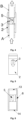
- FIG. 1 shows a general view of the airter of the first type (type "one"), a three-channel version (with three gas injectors),
- Fig. 2 shows a transverse breakaway through the airter shown in Fig. 1 exposing three gas channels of the gas injector shown
- Fig. 3 shows a view of the airter same as in Fig. 1 mounted on the supply conduit
- Fig. 4 shows an axial cross section of the three-channel gas injector airter installed on a supply conduit
- Fig. 5 shows the airter viewed from the upstream side of the gas injector channel inlet
- Fig. 6 shows an axial cross section of the airter
- Fig. 1 shows a general view of the airter of the first type (type "one"), a three-channel version (with three gas injectors)
- Fig. 2 shows a transverse breakaway through the airter shown in Fig. 1 exposing three gas channels of the gas injector shown
- Fig. 3 shows a view of the airter same as
- FIG. 7 shows a view of a three-channel (comprising three gas injectors) airter, from the upstream side
- Fig. 8 is an enlarged view of the three-channel airter from the downstream side
- Fig. 9 shows an enlarged axial cross-section of a single gas injector channel of the airter, mounted on the upstream side the supply conduit and the downstream side of the supply conduit, where a part of the body wall of the airter and the supply conduit are shown only to one side, the space external to the supply conduit is on the right side of the drawing, and to the left side of this figure is the space external to the supply conduit
- Fig. 10 shows a view of the airter from the downstream side, depicting a variant with four channels (four gas injectors), Fig.
- FIG. 11 shows the second type (type "two") of the airter three-channel version (comprising three gas injectors), in Fig. 12 a third type (type "three") of the airter with a single gas injector, from the upstream side, is shown, Fig. 13 is an overall view of the airter with a single gas injector same as in Fig. 12 , shown from the downstream side, Fig. 14 shows a general view of the airter from Fig. 12 , with a single gas injector mounted on the supply tube, a cutaway of the supply conduit is also shown, Fig. 15 shows the three-channel (three gas injectors) airter of Fig.
- Fig. 16 shows the longitudinal breakaway (the inner part), viewed from the downstream side, of a three-channel (comprising three gas injectors) airter of the first type, in the variant with an added stator mounted on the upstream side
- Fig. 17 shows the stator from the downstream side
- Fig. 18 shows a diagram of a portable fire extinguisher equipped with two separate airters mounted on the same supply conduit (a plunger or a siphon or a dip tube, a supply tube), and Fig.
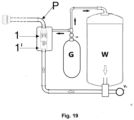
- FIG. 19 shows a diagram of an exemplar system of two linearly (serially) linked airters mounted on a common conduit, which is supplying the distribution installation, and having a dedicated common gas supply to the injector inlet channels of both sets of airter gas injectors.
- Figures 1 to 9 and Figures 15 and 16 show a three-channel (three gas injectors) airter of the first type, with a body in the form of a tubular socket
- Figure 10 shows an analogous airter of the first type, but in the four-channel variant
- Fig. 11 shows the second type of an airter
- Fig. 12 , Fig. 13 and Fig. 14 show the third type of an airter with a body in the form of a section of a tubular socket.
- Known liquid atomising devices are typically equipped with a reservoir W holding liquid (water or aqueous solutions), a source of a pressurized gas G which is either a space over the liquid surface in the reservoir holding liquid, or a gas cartridge within this reservoir, or an external gas vessel, a supply conduit, for example supply tube, and the necessary auxiliary fit-out, comprising a system for generating a two-phase liquid-gas mixture, preferably creating effervescent flows.
- a reservoir W holding liquid (water or aqueous solutions)
- a source of a pressurized gas G which is either a space over the liquid surface in the reservoir holding liquid, or a gas cartridge within this reservoir, or an external gas vessel
- a supply conduit for example supply tube
- the necessary auxiliary fit-out comprising a system for generating a two-phase liquid-gas mixture, preferably creating effervescent flows.
- auxiliary fit-out also includes other elements, e.g., sensors, indicators, valves such as the gas release/reduction valve VR and the bleed valve Vo of the system, brackets, possibly the apparatus cover, etc. These elements are known to the person skilled in the art, and are selected depending on the dedicated applications and do not constitute the subject of the invention.
- the supply conduit P may be a rigid pipe, preferably positioned vertically in the container holding the liquid, or a supply tube flexible to some extent, by the same token the supply conduit P may be a single element or be fabricated in sections, e.g., two, three, four tube sections, eventually combined into a single supply conduit P.
- supply conduit and “supply tube” can be used interchangeably as having the same meaning.
- the supply conduit P or its sections contain the inlet part of the supply tube A and the outlet part of the supply tube B.
- the known supply conduit P is provided with openings through which pressurized gas is injected from the space outside of the tube into the tube inner space (tube inner channel) typically filled with water or its solutions during the operation of the apparatus.
- pressurized gas is injected from the space outside of the tube into the tube inner space (tube inner channel) typically filled with water or its solutions during the operation of the apparatus.
- An improved portion of the supply conduit P is presented below, and it is provided with an airter comprising channels to divert gas from the space outside the supply tube P to its interior.
- the airter 1, 1', 1" for generating effervescent flows in a liquid atomising device is a separate element which is set leakproof on the supply conduit P and comprises a cylindrical or part-cylinder (section) body 2, 2', 2", outfitted with at least one gas injector, which is in the form of a pass-through, streamlined gas injector channel 3 led through the wall 6 of the body 2, 2', 2", limited by the internal surface of the channel housing 7, and said gas injector channel 3 tapers within the exit part of the channel housing 4 towards the exit port 9 located on the downstream wall of the channel housing 8.
- the gas injector channel 3 is curved so that its inlet is located on the outer side of the body 2, 2', 2 " whereas its exit port 9 located on the inside of the body 2, 2', 2" is orientated upwards (in the direction of the discharge of the liquid atomising device), and the exit port 9 is positioned axially in relation to the supply conduit P, in its inner space.
- the gas injector channel 3 redirects the gas stream from the inlet orientation, approximately perpendicular to the outer surface of the body 2, 2', 2", and also perpendicular to the longitudinal axis of the supply conduit P, to the intended direction - consistent with the longitudinal axis of the supply conduit P, towards the discharge nozzle (or a set of nozzles) of the liquid atomising device.
- the airter 1, 1', 1" is also provided with the first mounting means 13, 14, 16 for mounting the body 2, 2', 2" on the supply conduit P of the liquid atomising device and/or the second mounting means 15 for securing adjacent airters 1, 1', arranged in a linear system (in series).
- airter includes three variants selected from the group consisting of: the first type of an airter 1, the second type of an airter 1' and the third type of an airter 1".
- airter and airter device have the same meaning.
- Any airter 1, 1', 1" of the mentioned group is equipped with a selected adequately shaped body 2, 2', 2" matched to an appropriately selected mounting means 13, 14, 15, 16.
- airter body encompasses three variants selected from the group consisting of a body 2 of a first type of airter 1, a body 2' of a second type of airter 1' and a body 2" of a third type of airter 1".
- the first type of the airter 1, shown as an example in Fig. 1 has a cylindrical (tubular) body 2, and is equipped with at least one (preferably two or three) rounded gas injector channel 3 wider at the gas inlet side and tapering towards the exit port 9 which is the narrowest element of the gas injector channel 3, and is at the same time limited by a curved outer surface of the channel housing 5, minimizing the resistance to the flow of liquid (or two-phase liquid-gas flow), the housing positioned to the wetted side of the supply conduit P.
- the first type of the airter 1 is equipped with technical means for sealing it on the supply conduit P in such a way that the supply conduit P is divided into sections which, in places where the airter is mounted at, include an inlet part of the supply tube A and an outlet part of the supply tube B.
- Body 2 joins the adjacent supply conduit P segments.
- the inlet part of the supply tube A and the outlet part of the supply tube B are provided with interference-fit rims to hold the airter 1. More specifically, the exit mounting shank 13 at the downstream end of the first type of airter 1 is set on the inlet part of the supply tube A (of the first section of the supply conduit P ) by pressing together these ends, which have properly matched diameters, i.e.
- the exit mounting shank 13 has an internal diameter matched to the external diameter of the inlet part of the supply tube A. Said diameters are approximately the same to ensure a interference fit connection.
- the inlet mounting shank 14 located at the inlet end of the first type of the airter 1 is set on the outlet part of the supply tube B (the second section of the supply conduit P ) by pressing together these terminals, having appropriately matched diameters, i.e., the inlet mounting shank 14 has an internal diameter matched to the outer diameter of the outlet part of the supply tube B.
- the inlet part of the supply tube A of the first section of the supply conduit P and the outlet part of the supply tube B of the second section of the supply tube P are sealed together by means of the first type airter 1.
- the supply conduit P may consist of more than two sections and include several e.g., two, three, four or five members of the type one of airter 1.
- the supply conduit P is made from three sections, it encompasses two specimen of type one airter 1, which are at the same time the connectors of these tube sections.
- a second specimen of the type one airter 1 is mounted, which is also connected to the outlet part of the supply tube B of the third section of the supply conduit P, as shown in Fig. 18 .
- Fig. 18 In this embodiment of the invention, ( Fig.
- the first, upper section of the supply conduit P is located in the upper end of the fire extinguisher and is the part of the supply conduit P channelling the liquid-gas mixture (a coarse mist) towards the exit nozzle
- the second, middle section of the supply conduit P is located between the first and third section of the supply conduit P
- the third, lower section of the supply conduit P is located in the lowermost part of the fire extinguisher and constitutes the bottom extremity of the entire supply conduit P, which may optionally be provided with a particulate matter filter and/or a liquid flow restrictor.
- the supply conduit P can be assembled from four sections and three members of the first type airter 1, or from five sections of the supply conduit P and four members of the first type airter 1.
- the second type of the airter 1' represented in Fig. 11 , has a structure analogous to the type one airter 1, with the difference that in the type two airter 1', at one end or at both ends of the cylindrical body 2' there is a male shank 15 (or female) for connection to another airter 1, 1', which may be a type one airter 1 or a type two airter 1'. In this way, two, three or more distinct types of airters 1, 1' can be connected in a linear (serial) mode.
- the body 2' of the type two airter 1' is similar to the type one airter 1 described just above, provided with at least one (preferably two or three) rounded gas injector channel 3 wider from the gas inlet side and tapering towards the exit port 9 which is the narrowest element of the gas injector channel 3.
- the gas injector channel 3 is also limited by an outer surface of the channel housing 5, rounded, minimizing-resistance to liquid flow (or two-phase, liquid-gas flow), and located on the wetted side of the supply conduit P.
- the type two airter 1' may be provided not only with technical means for leak-proof connecting it to another member of the type two airter 1' (or to another member of the type one airter 1 ) but also, at the other end of the body 2', using technical means for leak proofing could be mounted on the supply conduit P.
- the connector of this type applies only to that end of the cylindrical body 2 which is dedicated to being connected to the supply conduit P or on a section thereof.
- An exemplary embodiment of such a variant of the invention is shown in Fig. 19 .
- the supply conduit P is composed of two sections of the supply conduit P - upper and lower ( Fig. 19 ). Between these sections of the supply conduit P, a type two airter 1' is inserted to the upstream side, and then, above it, a type one airter 1, which is then connected to the upper section of the supply conduit P, through which, in this device for atomising liquid, the liquid-gas mixture discharges through the exit nozzle.
- the exit mounting shank 13 at the downstream end of the type one airter 1 is positioned on the inlet part of the supply tube A (upper segment of the supply conduit P ) by pushing the inlet part of the supply tube A into the exit mounting shank 13 having a suitably matched/adjusted diameter.
- the inlet mounting shank 14 located at the upstream end of the type one airter 1 is mounted on the male mounting shank 15 of the type two airter 1'.
- the exit mounting shank 13 is interference-fitted to the inlet part of the supply tube A of the upper section of the supply tube P.
- the outer diameter (OD) of the male mounting shank 15 is the same as the OD of the inlet part of the supply tube A and the outlet part of the supply tube B.
- the inlet mounting shank 14 and the exit mounting shank 13 are sized to both the supply conduit P and the male mounting shank 15.
- the supply conduit P may consist of more than two section and comprise several e.g., two, three, four or five members of the type one airter 1 and/or the type two airter 1' .
- the supply conduit P is composed of three sections, many different arrangements between the individual members of the type one 1 airters and/or type two 1' airters in-between the individual sections of the supply conduit are workable. It is possible that two identical sets of the type one airter 1 mounted on the male mounting shank 15 of the type two airter 1' will be positioned between the supply conduit P sections.
- a set of two airters 1, 1' is used, i.e., the type one airter 1 mounted on the male mounting shank 15 of the type two airter 1', and on the other linkage of the conduit sections, one airter of the type one 1 will be used.
- Various gas airters 1, 1' may also be connected in series (a linear system), in arrangements of three or four airters 1, 1' of both types one and two.
- the third type of the airter 1 differs from the above-described types of airters one and two 1, 1' in that its body 2" is in the form of a bridge (or a horseshoe), which is a portion of a cylinder (to the inside, from the side of the supply conduit P ) , in other words, an incomplete cylinder.
- the term "cylinder portion” should be understood as an element with a cylindrical (hoop) form over a part of more than 50% of the circumference, with the cylindrical shape obligatory only from the inside of this element, where it mates the supply conduit P.
- the body 2" of the type three airter 1" may or may not have a different rounded shape, and be a polyhedron, cuboid, etc.
- the type three airter 1" is mounted on the supply conduit P by pressing the body 2" onto the supply conduit P from the side, perpendicularly to the longitudinal axis of the supply conduit P.
- the third type of airter 1" consists of a body 2", which is provided with one rounded gas injector channel 3, wider at the gas inlet side and tapering towards the exit port 9.
- Exit port 9 is the narrowest element of the gas injector channel 3, which is at the same time limited by a rounded outer surface of the housing of the channel 5", minimizing liquid flow resistance (or two-phase flow of the liquid-gas system), and located on the wetted side of the supply conduit P.
- the type three gas airter 1" is provided with technical means for leakproof fixing it on the supply conduit P to the effect that the supply conduit P has an opening, preferably circular, at the location of the airter 1" mounted thereon.
- the supply conduit P is one continuous tube (it is not divided into sections).
- the body 2" of the third type of airter 1" is furnished with two opposite gripper jaws 16, which enable the third type of airter 1" to be snapped onto the supply conduit P.
- the body 2" together with gripper jaws 16 is flexible, which enables - when pressed - to temporarily widen the space between the gripper jaws 16 to slide the body onto the supply conduit P, in the place where the side opening in the wall of the supply conduit P is made, to place a channel 3 in this side opening, the gas channel ending with an exit port 9.
- the body 2" to the inner side is provided with a channel housing foot 17, which is shaped to match the side opening in the supply conduit P, preferably the channel housing foot 17 is circular and the side opening in the supply conduit P is also circular.
- the channel housing foot 17 performs a fastening and sealing function, and an exit port 9 run (from the gas channel) is led out of it.
- the tightness of the described solution can also be ensured using an adhesive, a fused joint, by using a gasket or a sealing lip around the perimeter of the channel housing foot 17.
- This third embodiment of the invention can be combined with the variants presented above using a type one airter 1 and a type two airter 1'.
- the supply conduit P may consist of two or more sections and include different arrangements of the type one airter 1 and the type two airter 1', and the supply conduit P may have side openings for receiving the type three airter 1" therein.
- the airter 1, 1', 1" may be provided with from 1 to 10 channels 3, wherein the type one airter 1 and the type two airter 1' are preferably provided with two, three or four channels 3, preferably positioned radially at equal distances from each other, around the circumference of the body 2, 2', e.g. in the case of three channels 3 they will be positioned at 120° intervals, at the same distance from the edge of the cylindrical body 2, 2'.
- the type three airter 1" is preferably provided with one channel 3, located on the body 2" opposite to the free space between the gripper jaws 16.
- All joints (links) made within the supply conduit P, between the sections of the supply conduit P, or the members of the supply conduit P and the airters 1, 1', 1" are leakproof, because the sizes of the connected elements are closely matched.
- Mounting means in the body 2, 2', 2" of the airters 1, 1', 1" and/or the respective shanks: the inlet section of the supply tube A and the outlet portion of the supply tube B may be, as described above, joined together on interference, but may also be selected from the group consisting of fused, crimped, threaded elements or elements with interlocking and/or sealing lips or include additional gaskets, sealants or have edges that are matched to each other such as tongue and groove joints.
- a stator 10 (shown in Fig. 17 ) is used. It is embedded in a mounting socket (recess in the wall of the body 2, 2' ) in the type one airter 1 or in the type two airter 1', in the inlet part upstream of the channels 3.
- stator 10 in the supply conduits when having a diameter similar to that of the downstream side of the exterior housing of the gas injector channel can be omitted or replaced with a particulate matter filter (a strainer) generating a pressure drop which is sufficiently high, in all other cases, it can also be embedded in the supply conduit P, in the appropriate socket (recess in the wall of the supply conduit P ) the upstream the type three airter 1" location.
- a particulate matter filter a strainer
- the stator 10 has a circular form (a shape of a disc) and is sized to match the cross-sectional diameter of the first and type one or two airters 1, 1' and is provided with round or oval passthrough holes 11, and their number and arrangement is tailored to the number and arrangement of channels 3 in the airters 1, 1' of the type one or two.
- the stator 10 is also provided with locking cogs 12 for aligning and followed by locking it in its projected position.
- the arrangement of the stator 10 inside the body 2 is shown in Fig. 15 and Fig. 16 .
- the stator 10 impedes the flow of liquid in the supply conduit P (in the body 2, 2' ) to a small extent, and at the same time through the passthrough holes 11 directs the flow of the liquid axially in the direction of the openings of the channels 3 located precisely behind these passthrough holes 11.
- the function of the stator 10 is to create (but only locally, due to the gas injection action downstream of it) a pressure differential as low as possible, yet sufficient to help inject gas into the main flow. This increases the efficiency of creating a finely divided liquid-gas mixture inside the airter 1, 1' and inside the supply conduit P while minimising the pressure drop of the mixture reaching the exit nozzle.
- the diameters of the type one or type two airters 1, 1' in the parts connected to the supply tube P segments are tailored so that the formed combined inner channel of the supply conduit P has a uniform diameter, i.e., adding bodies 2, 2', 2" does not cause significant irregularity inside the channel of the supply conduit P. Consequently, when the cylindrical body 2, 2' of the first and second types of airters 1, 1' is referred to in the present description, it is the cylindrical body outside of the supply channel, and in the inner space, the body 2, 2' includes circumferential steps offsetting the thickness of the walls of the supply conduit P sections reaching inside the body.
- the solution according to the invention ensures the redirection of gas streams from the space outside the supply conduit towards the axis of the main stream in the internal duct of the supply conduit and is intended to significantly increase the (static) pressure of the mixture of phases downstream of the gas injection location, which in turn is executed via the exit openings (ports) of the gas injector.
- the proposed improvements result in a significant upgrade in performance of the dispersion nozzle (or nozzles), where primarily the effervescent type of two-phase flow will be maintained, i.e., containing the largest possible number of small gas bubbles carried in the stream of liquid.
Landscapes
- Nozzles (AREA)
Abstract
The airter device for generating effervescent flows in a liquid atomising device, according to the invention is characterized in that the airter device comprises a body provided with at least one gas injector, mounting means for securing the body to the supply conduit of the liquid atomising device and/or mounting means for securing adjacent, aligned, airters on the supply conduit, the gas injector comprises a channel of the gas injector led through the wall of the body, tapering towards the exit port, curved so that the inlet is located on the outer side of the body, and on the inner side of the body there is an exit port of the channel of the gas injector, the exit port is axially located in relation to the longitudinal axis of the supply conduit, in the inner space of the supply conduit. The subject of this invention is also a liquid atomising device comprising at least one airter mounted on the supply conduit P.
Description
- The subject of the invention is an airter device to generate effervescent flows and the liquid atomising device comprising the airter device.
- A solution for an airter to generate effervescent flows in (predominantly) portable misting devices is presented herein. The device is intended specifically for a low-pressure gas-liquid feed-stream efficient generation of mist.
- Liquid spraying devices known to date are connected to a reservoir e.g. a pressure cylinder, holding a liquid e.g. water, here the liquid can be held combined with motive gas (in so called "stored pressure devices"), or in a cartridge inside of or connected to that reservoir, or having the water source integrated with an external source of gas under pressure causing said liquid displacement from the reservoir and through the siphon tube, so that the mist is effectively generated when reaching the exit nozzle(s).
- Devices of this type can be used in pharmacy, cosmetics industries, also as plant spraying devices, disinfecting devices, in construction, dust control, industry (e.g., paint coating), a wide class of fire extinguishing systems, and fire extinguishers are a special case of the device under consideration.
- Fire extinguishers containing water or water solutions as an extinguishing medium and using compressed gas, where a highly dispersed mist stream is generated, which is useful for extinguishing purposes and meeting the normative requirements for water-based extinguishers are called mist or water-mist extinguishers. Mist generation can be accomplished in two different ways, i.e., it is possible to dynamically disperse a homogeneous stream or streams of liquid exiting a single-phase exit dispersion head, in a process, which requires relatively high supply pressures. Or when a two-phase supply is assured (where the gas and liquid supply lines to the head are not distinct) rapid fragmentation of the gas-liquid interfaces takes place inside and just aft the dispersion head attaining the level of dispersion comparative to the former case but at the lower pressure of the supplied fluid stream. In the latter case, especially when the head is provisioned directly with a mixture of liquid and gas, it is necessary to develop improved head designs that perform efficiently at reduced pressure and the lowest possible gas demand.
- From the international patent application
WO2017160173A1 a device ensuring a two-phase flow in a liquid atomiser is known, and it is equipped in its upper part with a discharge control assembly, the device contains at least one egress channel, as well as a plunger tube, placed below this assembly and interconnected with this assembly, the plunger tube having in its lowermost segment an ingress channel, optionally outfitted with a filter to keep away impurities, and interconnected with a discharge control assembly, and further downstream with an egress channel, wherein the plunger tube is outfitted with a liquid flow restrictor and, above the restrictor, a row of side openings connecting external space of the tube with its inner channel, where the successive side openings are positioned longitudinally along the tube at different distances from the restrictor. - The airter device for generating effervescent flows in a liquid atomising device, according to the present invention is characterized in that the airter device comprises a body provided with at least one gas injector, mounting means for securing the body to the supply conduit of the liquid atomising device and/or mounting means for securing adjacent, aligned, airters on the supply conduit, the gas injector comprises a channel of the gas injector led through the wall of the body, tapering towards the exit port, curved so that the inlet is located on the outer side of the body, and on the inner side of the body there is an exit port of the channel of the gas injector, the exit port is axially located in relation to the longitudinal axis of the supply conduit, in the inner space of the supply conduit.
- Preferably, the internal diameter of the body, in the section of the exit mounting shank and the inlet mounting shank, is closely matched to the outer diameter of the supply conduit of the liquid atomising device.
- Preferably, airter is selected from the group consisting of a first type of airter comprising a body in cylindrical form, a second type of airter comprising a body in a cylindrical form, and a third type of airter comprising a body in the form of a bridge formed on the inside as a section of a cylinder.
- Preferably, airter of the first and second type includes two or three or four gas injectors arranged radially at equal distances from each other on the circumference of the body, at the same height within the body.
- Preferably, the third type of airter comprises one gas injector.
- Preferably, the mounting means securing the body on the supply conduit of the liquid atomising device are selected from the group consisting of exit mounting shanks, inlet mounting shanks and gripper jaws.
- Preferably, the mounting means securing the adjacent airters to each other are in the form of a male mounting shank embedded in the seat of the adjacent airter.
- The subject of the invention is also a liquid atomising device comprising a tank holding a liquid, a reservoir holding a gas source, a supply conduit and auxiliary equipment, characterized in that at least one airter as defined above is mounted on the supply conduit.
- The subject of the invention in an exemplary embodiment is exhibited in the drawings, where
Fig. 1 shows a general view of the airter of the first type (type "one"), a three-channel version (with three gas injectors),Fig. 2 shows a transverse breakaway through the airter shown inFig. 1 exposing three gas channels of the gas injector shown,Fig. 3 shows a view of the airter same as inFig. 1 mounted on the supply conduit,Fig. 4 shows an axial cross section of the three-channel gas injector airter installed on a supply conduit,Fig. 5 shows the airter viewed from the upstream side of the gas injector channel inlet,Fig. 6 shows an axial cross section of the airter,Fig. 7 shows a view of a three-channel (comprising three gas injectors) airter, from the upstream side,Fig. 8 is an enlarged view of the three-channel airter from the downstream side,Fig. 9 shows an enlarged axial cross-section of a single gas injector channel of the airter, mounted on the upstream side the supply conduit and the downstream side of the supply conduit, where a part of the body wall of the airter and the supply conduit are shown only to one side, the space external to the supply conduit is on the right side of the drawing, and to the left side of this figure is the space external to the supply conduit,Fig. 10 shows a view of the airter from the downstream side, depicting a variant with four channels (four gas injectors),Fig. 11 shows the second type (type "two") of the airter three-channel version (comprising three gas injectors), inFig. 12 a third type (type "three") of the airter with a single gas injector, from the upstream side, is shown,Fig. 13 is an overall view of the airter with a single gas injector same as inFig. 12 , shown from the downstream side,Fig. 14 shows a general view of the airter fromFig. 12 , with a single gas injector mounted on the supply tube, a cutaway of the supply conduit is also shown,Fig. 15 shows the three-channel (three gas injectors) airter ofFig. 1 mounted on the upstream side of the supply conduit and the downstream side of the supply conduit, in the variant with an added stator mounted on the upstream side,Fig. 16 shows the longitudinal breakaway (the inner part), viewed from the downstream side, of a three-channel (comprising three gas injectors) airter of the first type, in the variant with an added stator mounted on the upstream side,Fig. 17 shows the stator from the downstream side,Fig. 18 shows a diagram of a portable fire extinguisher equipped with two separate airters mounted on the same supply conduit (a plunger or a siphon or a dip tube, a supply tube), andFig. 19 shows a diagram of an exemplar system of two linearly (serially) linked airters mounted on a common conduit, which is supplying the distribution installation, and having a dedicated common gas supply to the injector inlet channels of both sets of airter gas injectors.Figures 1 to 9 andFigures 15 and16 show a three-channel (three gas injectors) airter of the first type, with a body in the form of a tubular socket,Figure 10 shows an analogous airter of the first type, but in the four-channel variant,Fig. 11 shows the second type of an airter, andFig. 12 ,Fig. 13 and Fig. 14 show the third type of an airter with a body in the form of a section of a tubular socket. - Known liquid atomising devices are typically equipped with a reservoir W holding liquid (water or aqueous solutions), a source of a pressurized gas G which is either a space over the liquid surface in the reservoir holding liquid, or a gas cartridge within this reservoir, or an external gas vessel, a supply conduit, for example supply tube, and the necessary auxiliary fit-out, comprising a system for generating a two-phase liquid-gas mixture, preferably creating effervescent flows. In the upper (exit) part of such a system there is at least one exit opening to discharge a two-phase mixture, preferably ended with a head (an exit dispersion nozzle), and below this system there is at least one supply conduit connected to it, having in its lowest part, optionally equipped with a particulate matter filter, the inlet of the supply channel. The mentioned auxiliary fit-out also includes other elements, e.g., sensors, indicators, valves such as the gas release/reduction valve VR and the bleed valve Vo of the system, brackets, possibly the apparatus cover, etc. These elements are known to the person skilled in the art, and are selected depending on the dedicated applications and do not constitute the subject of the invention. For the purposes of the invention, the supply conduit P may be a rigid pipe, preferably positioned vertically in the container holding the liquid, or a supply tube flexible to some extent, by the same token the supply conduit P may be a single element or be fabricated in sections, e.g., two, three, four tube sections, eventually combined into a single supply conduit P. In the present description terms "supply conduit" and "supply tube" can be used interchangeably as having the same meaning. The supply conduit P or its sections contain the inlet part of the supply tube A and the outlet part of the supply tube B.
- In order to generate a mixture of water and motive gas, the known supply conduit P is provided with openings through which pressurized gas is injected from the space outside of the tube into the tube inner space (tube inner channel) typically filled with water or its solutions during the operation of the apparatus. In various devices, converting of water and gas mixture to a mist is achieved in many different ways, e.g., by secondary breaking of gas bubbles and creating a required mist composed of fine water droplets.
- An improved portion of the supply conduit P is presented below, and it is provided with an airter comprising channels to divert gas from the space outside the supply tube P to its interior.
- The
airter body gas injector channel 3 led through thewall 6 of thebody gas injector channel 3 tapers within the exit part of thechannel housing 4 towards theexit port 9 located on the downstream wall of thechannel housing 8. Thegas injector channel 3 is curved so that its inlet is located on the outer side of thebody exit port 9 located on the inside of thebody exit port 9 is positioned axially in relation to the supply conduit P, in its inner space. Thus, thegas injector channel 3 redirects the gas stream from the inlet orientation, approximately perpendicular to the outer surface of thebody - The
airter body adjacent airters 1, 1', arranged in a linear system (in series). - The term "airter" includes three variants selected from the group consisting of: the first type of an
airter 1, the second type of an airter 1' and the third type of anairter 1". In this description term "airter" and "airter device" have the same meaning. - Any
airter body - The term airter "body" encompasses three variants selected from the group consisting of a
body 2 of a first type ofairter 1, a body 2' of a second type of airter 1' and abody 2" of a third type ofairter 1". - The first type of the
airter 1, shown as an example inFig. 1 , has a cylindrical (tubular)body 2, and is equipped with at least one (preferably two or three) roundedgas injector channel 3 wider at the gas inlet side and tapering towards theexit port 9 which is the narrowest element of thegas injector channel 3, and is at the same time limited by a curved outer surface of thechannel housing 5, minimizing the resistance to the flow of liquid (or two-phase liquid-gas flow), the housing positioned to the wetted side of the supply conduit P. The first type of theairter 1 is equipped with technical means for sealing it on the supply conduit P in such a way that the supply conduit P is divided into sections which, in places where the airter is mounted at, include an inlet part of the supply tube A and an outlet part of the supplytube B. Body 2 joins the adjacent supply conduit P segments. The inlet part of the supply tube A and the outlet part of the supply tube B are provided with interference-fit rims to hold theairter 1. More specifically, theexit mounting shank 13 at the downstream end of the first type ofairter 1 is set on the inlet part of the supply tube A (of the first section of the supply conduit P) by pressing together these ends, which have properly matched diameters, i.e. theexit mounting shank 13 has an internal diameter matched to the external diameter of the inlet part of the supply tube A. Said diameters are approximately the same to ensure a interference fit connection. In turn, theinlet mounting shank 14 located at the inlet end of the first type of theairter 1 is set on the outlet part of the supply tube B (the second section of the supply conduit P) by pressing together these terminals, having appropriately matched diameters, i.e., theinlet mounting shank 14 has an internal diameter matched to the outer diameter of the outlet part of the supply tube B. Thus, the inlet part of the supply tube A of the first section of the supply conduit P and the outlet part of the supply tube B of the second section of the supply tube P are sealed together by means of thefirst type airter 1. For a skilled person in a given field, it will be obvious how to achieve a tight and durable connection of the airter with the supply conduit section or with each other. Representative embodiments, in addition to gluing or fusing, may also be based on a crimped or threaded shanks, or a combination thereof, with or without sealing elements such as gaskets or sealants. Correct (i.e., tight, and not generating additional resistance to fluid flow) connections will not affect the operating parameters of the device, but only the cost of its production. - In this variant of the invention, the supply conduit P may consist of more than two sections and include several e.g., two, three, four or five members of the type one of
airter 1. For example, if the supply conduit P is made from three sections, it encompasses two specimen of type oneairter 1, which are at the same time the connectors of these tube sections. On the inlet part of the supply tube A of the second section of the supply conduit P, a second specimen of the type oneairter 1 is mounted, which is also connected to the outlet part of the supply tube B of the third section of the supply conduit P, as shown inFig. 18 . In this embodiment of the invention, (Fig. 18 ), the first, upper section of the supply conduit P is located in the upper end of the fire extinguisher and is the part of the supply conduit P channelling the liquid-gas mixture (a coarse mist) towards the exit nozzle, the second, middle section of the supply conduit P is located between the first and third section of the supply conduit P, and the third, lower section of the supply conduit P is located in the lowermost part of the fire extinguisher and constitutes the bottom extremity of the entire supply conduit P, which may optionally be provided with a particulate matter filter and/or a liquid flow restrictor. - Similarly, as described above, the supply conduit P can be assembled from four sections and three members of the
first type airter 1, or from five sections of the supply conduit P and four members of thefirst type airter 1. - The second type of the airter 1', represented in
Fig. 11 , has a structure analogous to the type oneairter 1, with the difference that in the type two airter 1', at one end or at both ends of the cylindrical body 2' there is a male shank 15 (or female) for connection to anotherairter 1, 1', which may be a type oneairter 1 or a type two airter 1'. In this way, two, three or more distinct types ofairters 1, 1' can be connected in a linear (serial) mode. The body 2' of the type two airter 1' is similar to the type oneairter 1 described just above, provided with at least one (preferably two or three) roundedgas injector channel 3 wider from the gas inlet side and tapering towards theexit port 9 which is the narrowest element of thegas injector channel 3. Thegas injector channel 3 is also limited by an outer surface of thechannel housing 5, rounded, minimizing-resistance to liquid flow (or two-phase, liquid-gas flow), and located on the wetted side of the supply conduit P. - In this embodiment of the invention, the type two airter 1' may be provided not only with technical means for leak-proof connecting it to another member of the type two airter 1' (or to another member of the type one airter 1) but also, at the other end of the body 2', using technical means for leak proofing could be mounted on the supply conduit P. In the case of embedding the type two airers 1' on the supply conduit P, it is designed analogously as described above for the first type of
airter 1, but the connector of this type applies only to that end of thecylindrical body 2 which is dedicated to being connected to the supply conduit P or on a section thereof. An exemplary embodiment of such a variant of the invention is shown inFig. 19 . The supply conduit P is composed of two sections of the supply conduit P - upper and lower (Fig. 19 ). Between these sections of the supply conduit P, a type two airter 1' is inserted to the upstream side, and then, above it, a type oneairter 1, which is then connected to the upper section of the supply conduit P, through which, in this device for atomising liquid, the liquid-gas mixture discharges through the exit nozzle. - More specifically, in this embodiment, the
exit mounting shank 13 at the downstream end of the type oneairter 1 is positioned on the inlet part of the supply tube A (upper segment of the supply conduit P) by pushing the inlet part of the supply tube A into theexit mounting shank 13 having a suitably matched/adjusted diameter. In turn, theinlet mounting shank 14 located at the upstream end of the type oneairter 1 is mounted on the male mounting shank 15 of the type two airter 1'. Further, theexit mounting shank 13 is interference-fitted to the inlet part of the supply tube A of the upper section of the supply tube P. Preferably, for the sake of simplifying the connection of different types ofairter 1, 1' to each other and/or connecting them to the supply conduit P, the outer diameter (OD) of the male mounting shank 15 is the same as the OD of the inlet part of the supply tube A and the outlet part of the supply tube B. Thus, theinlet mounting shank 14 and theexit mounting shank 13 are sized to both the supply conduit P and the male mounting shank 15. - In the above embodiment of the invention, the supply conduit P may consist of more than two section and comprise several e.g., two, three, four or five members of the type one
airter 1 and/or the type two airter 1'. For example, if the supply conduit P is composed of three sections, many different arrangements between the individual members of the type one 1 airters and/or type two 1' airters in-between the individual sections of the supply conduit are workable. It is possible that two identical sets of the type oneairter 1 mounted on the male mounting shank 15 of the type two airter 1' will be positioned between the supply conduit P sections. In another variant, it is possible that on one connection of the supply conduit P sections, a set of twoairters 1, 1' is used, i.e., the type oneairter 1 mounted on the male mounting shank 15 of the type two airter 1', and on the other linkage of the conduit sections, one airter of the type one 1 will be used.Various gas airters 1, 1' may also be connected in series (a linear system), in arrangements of three or fourairters 1, 1' of both types one and two. - The third type of the
airter 1", represented inFig. 12 , differs from the above-described types of airters one and two 1, 1' in that itsbody 2" is in the form of a bridge (or a horseshoe), which is a portion of a cylinder (to the inside, from the side of the supply conduit P), in other words, an incomplete cylinder. The term "cylinder portion" should be understood as an element with a cylindrical (hoop) form over a part of more than 50% of the circumference, with the cylindrical shape obligatory only from the inside of this element, where it mates the supply conduit P. From the outside, thebody 2" of the type threeairter 1" may or may not have a different rounded shape, and be a polyhedron, cuboid, etc. Following this form, the type threeairter 1" is mounted on the supply conduit P by pressing thebody 2" onto the supply conduit P from the side, perpendicularly to the longitudinal axis of the supply conduit P. The third type ofairter 1" consists of abody 2", which is provided with one roundedgas injector channel 3, wider at the gas inlet side and tapering towards theexit port 9.Exit port 9 is the narrowest element of thegas injector channel 3, which is at the same time limited by a rounded outer surface of the housing of thechannel 5", minimizing liquid flow resistance (or two-phase flow of the liquid-gas system), and located on the wetted side of the supply conduit P. The type threegas airter 1" is provided with technical means for leakproof fixing it on the supply conduit P to the effect that the supply conduit P has an opening, preferably circular, at the location of theairter 1" mounted thereon. In this variant of the invention (shown inFig. 14 ), the supply conduit P is one continuous tube (it is not divided into sections). Thebody 2" of the third type ofairter 1" is furnished with twoopposite gripper jaws 16, which enable the third type ofairter 1" to be snapped onto the supply conduit P. Thebody 2" together withgripper jaws 16 is flexible, which enables - when pressed - to temporarily widen the space between thegripper jaws 16 to slide the body onto the supply conduit P, in the place where the side opening in the wall of the supply conduit P is made, to place achannel 3 in this side opening, the gas channel ending with anexit port 9. - The
body 2" to the inner side is provided with achannel housing foot 17, which is shaped to match the side opening in the supply conduit P, preferably thechannel housing foot 17 is circular and the side opening in the supply conduit P is also circular. Thechannel housing foot 17 performs a fastening and sealing function, and anexit port 9 run (from the gas channel) is led out of it. The tightness of the described solution can also be ensured using an adhesive, a fused joint, by using a gasket or a sealing lip around the perimeter of thechannel housing foot 17. - This third embodiment of the invention can be combined with the variants presented above using a type one
airter 1 and a type two airter 1'. The supply conduit P may consist of two or more sections and include different arrangements of the type oneairter 1 and the type two airter 1', and the supply conduit P may have side openings for receiving the type threeairter 1" therein. - The
airter channels 3, wherein the type oneairter 1 and the type two airter 1' are preferably provided with two, three or fourchannels 3, preferably positioned radially at equal distances from each other, around the circumference of thebody 2, 2', e.g. in the case of threechannels 3 they will be positioned at 120° intervals, at the same distance from the edge of thecylindrical body 2, 2'. On the other hand, the type threeairter 1" is preferably provided with onechannel 3, located on thebody 2" opposite to the free space between thegripper jaws 16. - All joints (links) made within the supply conduit P, between the sections of the supply conduit P, or the members of the supply conduit P and the
airters body airters - In the variants of the invention described above, optionally, a stator 10 (shown in
Fig. 17 ) is used. It is embedded in a mounting socket (recess in the wall of thebody 2, 2') in the type oneairter 1 or in the type two airter 1', in the inlet part upstream of thechannels 3. In the type threeairter 1", thestator 10 in the supply conduits when having a diameter similar to that of the downstream side of the exterior housing of the gas injector channel can be omitted or replaced with a particulate matter filter (a strainer) generating a pressure drop which is sufficiently high, in all other cases, it can also be embedded in the supply conduit P, in the appropriate socket (recess in the wall of the supply conduit P) the upstream the type threeairter 1" location. Thestator 10 has a circular form (a shape of a disc) and is sized to match the cross-sectional diameter of the first and type one or twoairters 1, 1' and is provided with round or oval passthrough holes 11, and their number and arrangement is tailored to the number and arrangement ofchannels 3 in theairters 1, 1' of the type one or two. Thestator 10 is also provided with lockingcogs 12 for aligning and followed by locking it in its projected position. The arrangement of thestator 10 inside thebody 2 is shown inFig. 15 andFig. 16 . Thestator 10 impedes the flow of liquid in the supply conduit P (in thebody 2, 2') to a small extent, and at the same time through the passthrough holes 11 directs the flow of the liquid axially in the direction of the openings of thechannels 3 located precisely behind these passthrough holes 11. The function of thestator 10 is to create (but only locally, due to the gas injection action downstream of it) a pressure differential as low as possible, yet sufficient to help inject gas into the main flow. This increases the efficiency of creating a finely divided liquid-gas mixture inside theairter 1, 1' and inside the supply conduit P while minimising the pressure drop of the mixture reaching the exit nozzle. - If
several airters lowest airter 1, 1' (in the case of a type one or a type two airter) or below in the supply conduit P in thethird case 1" is sufficient. - In the solutions presented above, individual elements are streamlined, without faults and irregularities that could impede the flow of liquid, gas, or liquid-gas mixture. For example, the diameters of the type one or type two
airters 1, 1' in the parts connected to the supply tube P segments are tailored so that the formed combined inner channel of the supply conduit P has a uniform diameter, i.e., addingbodies cylindrical body 2, 2' of the first and second types ofairters 1, 1' is referred to in the present description, it is the cylindrical body outside of the supply channel, and in the inner space, thebody 2, 2' includes circumferential steps offsetting the thickness of the walls of the supply conduit P sections reaching inside the body. - The solution according to the invention ensures the redirection of gas streams from the space outside the supply conduit towards the axis of the main stream in the internal duct of the supply conduit and is intended to significantly increase the (static) pressure of the mixture of phases downstream of the gas injection location, which in turn is executed via the exit openings (ports) of the gas injector. The proposed improvements result in a significant upgrade in performance of the dispersion nozzle (or nozzles), where primarily the effervescent type of two-phase flow will be maintained, i.e., containing the largest possible number of small gas bubbles carried in the stream of liquid.
-
- A
- the inlet part of the supply tube
- B
- the outlet part of the supply tube
- P
- the supply conduit
- W
- the tank holding liquid
- G
- the pressure vessel holding gas
- VR
- gas release/reducing valve
- Vo
- system bleed valve
- 1
- the airter of the first type (type one)
- 1'
- the airter of the second type (type two)
- 1"
- the airter of the third type (type three)
- 2
- the body of the type one airter
- 2'
- the body of the type two airter
- 2"
- the body of the type three airter
- 3
- the gas injector channel
- 4
- the exit part of the gas channel housing
- 5
- the outer surface of the housing of the gas injector channel of the type one or two airters
- 5"
- the outer surface of the housing of the gas injector channel of the type three airter
- 6
- the wall of the body of the airter
- 7
- the internal surface of the gas channel housing
- 8
- the downstream wall of the gas channel housing
- 9
- the exit port (gas)
- 10
- the stator
- 11
- the passthrough hole of the stator
- 12
- the locking cog
- 13
- the exit mounting shank
- 14
- the inlet mounting shank
- 15
- the male mounting shank
- 16
- the gripper jaws
- 17
- the gas channel housing foot
Claims (8)
- Airter device for generating effervescent flows in a liquid atomising device, characterized in that the airter device (1, 1', 1") comprises a body (2, 2', 2") provided with at least one gas injector, mounting means (13, 14, 16) for securing the body (2, 2', 2") to the supply conduit P of the liquid atomising device and/or mounting means (15) for securing adjacent, aligned, airters (1, 1') on the supply conduit P, the gas injector comprises a channel of the gas injector (3) led through the wall of the body (2, 2', 2"), tapering towards the exit port (9), curved so that the inlet is located on the outer side of the body (2, 2', 2"), and on the inner side of the body (2, 2', 2") there is an exit port (9) of the channel of the gas injector (3), the exit port (9) is axially located in relation to the longitudinal axis of the supply conduit P, in the inner space of the supply conduit P.
- Airter according to claim 1, characterized in that the internal diameter of the body (2, 2'), in the section of the exit mounting shank (13) and the inlet mounting shank (14), is closely matched to the outer diameter of the supply conduit P of the liquid atomising device.
- Airter according to claim 1 or 2, characterized in that the gas airter (1, 1', 1") is selected from the group consisting of a first type of airter (1) comprising a body (2) in cylindrical form, a second type of airter (1') comprising a body (2') in a cylindrical form, and a third type of airter (1") comprising a body (2") in the form of a bridge formed on the inside as a section of a cylinder.
- Airter according to claim 1 or 2 or 3, characterized in that the airter (1, 1') of the first and second type includes two or three or four gas injectors arranged radially at equal distances from each other on the circumference of the body (2, 2'), at the same height within the body (2, 2').
- Airter according to any of the claims from 1 to 4, characterized in that the third type of airter (1") comprises one gas injector.
- Airter according to any of the claims from 1 to 5, characterized in that the mounting means (13, 14, 16) securing the body (2, 2', 2") on the supply conduit P of the liquid atomising device are selected from the group consisting of exit mounting shanks (13), inlet mounting shanks (14) and gripper jaws (16).
- Airter according to any of the claims from 1 to 6, characterized in that the mounting means (15) securing the adjacent airters (1, 1') to each other are in the form of a male mounting shank (15) embedded in the seat of the adjacent airter (1, 1').
- A liquid atomising device comprising a tank holding a liquid, a reservoir holding a gas source, a supply conduit and auxiliary equipment, characterized in that at least one airter (1, 1', 1") according to claim 1 is mounted on the supply conduit P.
Priority Applications (1)
| Application Number | Priority Date | Filing Date | Title |
|---|---|---|---|
| EP23020017.2A EP4400218A1 (en) | 2023-01-13 | 2023-01-13 | Airter device to generate effervescent flows and related liquid atomising device |
Applications Claiming Priority (1)
| Application Number | Priority Date | Filing Date | Title |
|---|---|---|---|
| EP23020017.2A EP4400218A1 (en) | 2023-01-13 | 2023-01-13 | Airter device to generate effervescent flows and related liquid atomising device |
Publications (1)
| Publication Number | Publication Date |
|---|---|
| EP4400218A1 true EP4400218A1 (en) | 2024-07-17 |
Family
ID=84981452
Family Applications (1)
| Application Number | Title | Priority Date | Filing Date |
|---|---|---|---|
| EP23020017.2A Withdrawn EP4400218A1 (en) | 2023-01-13 | 2023-01-13 | Airter device to generate effervescent flows and related liquid atomising device |
Country Status (1)
| Country | Link |
|---|---|
| EP (1) | EP4400218A1 (en) |
Citations (5)
| Publication number | Priority date | Publication date | Assignee | Title |
|---|---|---|---|---|
| US20100006670A1 (en) * | 2006-10-04 | 2010-01-14 | Siemens S.A.S. | Device for ejecting a diphasic mixture |
| US9296549B2 (en) * | 2009-11-17 | 2016-03-29 | The Salford Valve Company Limited | Spray discharge assembly |
| WO2017160173A1 (en) | 2016-03-17 | 2017-09-21 | Swiderski, Jerzy | Device ensuring two-phase flow in a liquid atomiser as well as a liquid atomiser containing such a device and a method of altering of a liquid atomiser |
| US20210331014A1 (en) * | 2018-08-22 | 2021-10-28 | Firemist Sp. Z.O.O. | A low-pressure mist fire extinguishing device and a set of components for a low-pressure mist fire extinguishing device |
| FR3115714A1 (en) * | 2020-10-30 | 2022-05-06 | État français représenté par le Préfet de police, agissant au nom et pour le compte de la Ville de Paris, relativement à la Brigade de Sapeurs-Pompiers de Paris | DEVICE FOR GENERATION OF A TWO-PHASE FLUID JET |
-
2023
- 2023-01-13 EP EP23020017.2A patent/EP4400218A1/en not_active Withdrawn
Patent Citations (5)
| Publication number | Priority date | Publication date | Assignee | Title |
|---|---|---|---|---|
| US20100006670A1 (en) * | 2006-10-04 | 2010-01-14 | Siemens S.A.S. | Device for ejecting a diphasic mixture |
| US9296549B2 (en) * | 2009-11-17 | 2016-03-29 | The Salford Valve Company Limited | Spray discharge assembly |
| WO2017160173A1 (en) | 2016-03-17 | 2017-09-21 | Swiderski, Jerzy | Device ensuring two-phase flow in a liquid atomiser as well as a liquid atomiser containing such a device and a method of altering of a liquid atomiser |
| US20210331014A1 (en) * | 2018-08-22 | 2021-10-28 | Firemist Sp. Z.O.O. | A low-pressure mist fire extinguishing device and a set of components for a low-pressure mist fire extinguishing device |
| FR3115714A1 (en) * | 2020-10-30 | 2022-05-06 | État français représenté par le Préfet de police, agissant au nom et pour le compte de la Ville de Paris, relativement à la Brigade de Sapeurs-Pompiers de Paris | DEVICE FOR GENERATION OF A TWO-PHASE FLUID JET |
Similar Documents
| Publication | Publication Date | Title |
|---|---|---|
| US4281683A (en) | Modular multiple-fluid component selection and delivery system | |
| US10989316B2 (en) | Dense phase pump with easily replaceable components | |
| AU651514B2 (en) | Regulated drip irrigation emitter | |
| KR100496835B1 (en) | Nested duckbilled check valve | |
| US7083121B2 (en) | Modular automatic spray gun manifold | |
| JPS6329120B2 (en) | ||
| CN204460179U (en) | Attemperator and the nozzle of ring type attemperator of assisting for steam | |
| AU2009254940B2 (en) | Mist generating apparatus and method | |
| CN101522310A (en) | Modular automatic spray gun manifold | |
| CN105636705B (en) | For the nozzle of distribution system | |
| WO2006062791A3 (en) | Membrane separation assemblies | |
| EP3259077B1 (en) | Sprayer adapter | |
| CA2580327A1 (en) | Fuel conveying member with side-brazed sealing members | |
| US20200038287A1 (en) | Dual plumbing system for a hot tub or spa | |
| US11920718B2 (en) | Additive manufactured liquid manifold with orifice | |
| EP1834122B1 (en) | Tubing connecting system | |
| EP2301632A1 (en) | Fire-extinguishing spray nozzle and fire-extinguishing equipment | |
| EP3543576B1 (en) | Dual plumbing system for a hot tub or spa | |
| US7699246B2 (en) | Supply system | |
| US9440200B2 (en) | Tube diffuser | |
| US20080105769A1 (en) | Compact check valve for spray nozzle | |
| ES2720204T3 (en) | Recirculation valve and fluid dispensing | |
| US20190290540A1 (en) | Dual plumbing system for a hot tub or spa | |
| US20200230634A1 (en) | Module for a modular changing device for coating materials and changing device for coating materials | |
| AU2014230794B2 (en) | A mist-generating apparatus and method |
Legal Events
| Date | Code | Title | Description |
|---|---|---|---|
| PUAI | Public reference made under article 153(3) epc to a published international application that has entered the european phase |
Free format text: ORIGINAL CODE: 0009012 |
|
| STAA | Information on the status of an ep patent application or granted ep patent |
Free format text: STATUS: THE APPLICATION HAS BEEN PUBLISHED |
|
| AK | Designated contracting states |
Kind code of ref document: A1 Designated state(s): AL AT BE BG CH CY CZ DE DK EE ES FI FR GB GR HR HU IE IS IT LI LT LU LV MC ME MK MT NL NO PL PT RO RS SE SI SK SM TR |
|
| STAA | Information on the status of an ep patent application or granted ep patent |
Free format text: STATUS: THE APPLICATION IS DEEMED TO BE WITHDRAWN |
|
| 18D | Application deemed to be withdrawn |
Effective date: 20250118 |