EP4400029A1 - Light source device and endoscope system - Google Patents
Light source device and endoscope system Download PDFInfo
- Publication number
- EP4400029A1 EP4400029A1 EP22867105.3A EP22867105A EP4400029A1 EP 4400029 A1 EP4400029 A1 EP 4400029A1 EP 22867105 A EP22867105 A EP 22867105A EP 4400029 A1 EP4400029 A1 EP 4400029A1
- Authority
- EP
- European Patent Office
- Prior art keywords
- light emission
- light
- period
- control unit
- preliminary
- Prior art date
- Legal status (The legal status is an assumption and is not a legal conclusion. Google has not performed a legal analysis and makes no representation as to the accuracy of the status listed.)
- Pending
Links
Images





Classifications
-
- A—HUMAN NECESSITIES
- A61—MEDICAL OR VETERINARY SCIENCE; HYGIENE
- A61B—DIAGNOSIS; SURGERY; IDENTIFICATION
- A61B1/00—Instruments for performing medical examinations of the interior of cavities or tubes of the body by visual or photographical inspection, e.g. endoscopes; Illuminating arrangements therefor
- A61B1/06—Instruments for performing medical examinations of the interior of cavities or tubes of the body by visual or photographical inspection, e.g. endoscopes; Illuminating arrangements therefor with illuminating arrangements
- A61B1/0655—Control therefor
-
- A—HUMAN NECESSITIES
- A61—MEDICAL OR VETERINARY SCIENCE; HYGIENE
- A61B—DIAGNOSIS; SURGERY; IDENTIFICATION
- A61B1/00—Instruments for performing medical examinations of the interior of cavities or tubes of the body by visual or photographical inspection, e.g. endoscopes; Illuminating arrangements therefor
- A61B1/00002—Operational features of endoscopes
- A61B1/00004—Operational features of endoscopes characterised by electronic signal processing
- A61B1/00006—Operational features of endoscopes characterised by electronic signal processing of control signals
-
- A—HUMAN NECESSITIES
- A61—MEDICAL OR VETERINARY SCIENCE; HYGIENE
- A61B—DIAGNOSIS; SURGERY; IDENTIFICATION
- A61B1/00—Instruments for performing medical examinations of the interior of cavities or tubes of the body by visual or photographical inspection, e.g. endoscopes; Illuminating arrangements therefor
- A61B1/00002—Operational features of endoscopes
- A61B1/00004—Operational features of endoscopes characterised by electronic signal processing
- A61B1/00009—Operational features of endoscopes characterised by electronic signal processing of image signals during a use of endoscope
-
- A—HUMAN NECESSITIES
- A61—MEDICAL OR VETERINARY SCIENCE; HYGIENE
- A61B—DIAGNOSIS; SURGERY; IDENTIFICATION
- A61B1/00—Instruments for performing medical examinations of the interior of cavities or tubes of the body by visual or photographical inspection, e.g. endoscopes; Illuminating arrangements therefor
- A61B1/00002—Operational features of endoscopes
- A61B1/00043—Operational features of endoscopes provided with output arrangements
- A61B1/00045—Display arrangement
-
- A—HUMAN NECESSITIES
- A61—MEDICAL OR VETERINARY SCIENCE; HYGIENE
- A61B—DIAGNOSIS; SURGERY; IDENTIFICATION
- A61B1/00—Instruments for performing medical examinations of the interior of cavities or tubes of the body by visual or photographical inspection, e.g. endoscopes; Illuminating arrangements therefor
- A61B1/06—Instruments for performing medical examinations of the interior of cavities or tubes of the body by visual or photographical inspection, e.g. endoscopes; Illuminating arrangements therefor with illuminating arrangements
- A61B1/0638—Instruments for performing medical examinations of the interior of cavities or tubes of the body by visual or photographical inspection, e.g. endoscopes; Illuminating arrangements therefor with illuminating arrangements providing two or more wavelengths
-
- A—HUMAN NECESSITIES
- A61—MEDICAL OR VETERINARY SCIENCE; HYGIENE
- A61B—DIAGNOSIS; SURGERY; IDENTIFICATION
- A61B1/00—Instruments for performing medical examinations of the interior of cavities or tubes of the body by visual or photographical inspection, e.g. endoscopes; Illuminating arrangements therefor
- A61B1/06—Instruments for performing medical examinations of the interior of cavities or tubes of the body by visual or photographical inspection, e.g. endoscopes; Illuminating arrangements therefor with illuminating arrangements
- A61B1/0661—Endoscope light sources
- A61B1/0684—Endoscope light sources using light emitting diodes [LED]
-
- G—PHYSICS
- G02—OPTICS
- G02B—OPTICAL ELEMENTS, SYSTEMS OR APPARATUS
- G02B23/00—Telescopes, e.g. binoculars; Periscopes; Instruments for viewing the inside of hollow bodies; Viewfinders; Optical aiming or sighting devices
- G02B23/24—Instruments or systems for viewing the inside of hollow bodies, e.g. fibrescopes
-
- G—PHYSICS
- G02—OPTICS
- G02B—OPTICAL ELEMENTS, SYSTEMS OR APPARATUS
- G02B23/00—Telescopes, e.g. binoculars; Periscopes; Instruments for viewing the inside of hollow bodies; Viewfinders; Optical aiming or sighting devices
- G02B23/24—Instruments or systems for viewing the inside of hollow bodies, e.g. fibrescopes
- G02B23/26—Instruments or systems for viewing the inside of hollow bodies, e.g. fibrescopes using light guides
-
- H—ELECTRICITY
- H04—ELECTRIC COMMUNICATION TECHNIQUE
- H04N—PICTORIAL COMMUNICATION, e.g. TELEVISION
- H04N23/00—Cameras or camera modules comprising electronic image sensors; Control thereof
- H04N23/10—Cameras or camera modules comprising electronic image sensors; Control thereof for generating image signals from different wavelengths
-
- H—ELECTRICITY
- H04—ELECTRIC COMMUNICATION TECHNIQUE
- H04N—PICTORIAL COMMUNICATION, e.g. TELEVISION
- H04N23/00—Cameras or camera modules comprising electronic image sensors; Control thereof
- H04N23/10—Cameras or camera modules comprising electronic image sensors; Control thereof for generating image signals from different wavelengths
- H04N23/125—Colour sequential image capture, e.g. using a colour wheel
-
- H—ELECTRICITY
- H04—ELECTRIC COMMUNICATION TECHNIQUE
- H04N—PICTORIAL COMMUNICATION, e.g. TELEVISION
- H04N23/00—Cameras or camera modules comprising electronic image sensors; Control thereof
- H04N23/50—Constructional details
- H04N23/555—Constructional details for picking-up images in sites, inaccessible due to their dimensions or hazardous conditions, e.g. endoscopes or borescopes
-
- H—ELECTRICITY
- H04—ELECTRIC COMMUNICATION TECHNIQUE
- H04N—PICTORIAL COMMUNICATION, e.g. TELEVISION
- H04N23/00—Cameras or camera modules comprising electronic image sensors; Control thereof
- H04N23/56—Cameras or camera modules comprising electronic image sensors; Control thereof provided with illuminating means
-
- H—ELECTRICITY
- H04—ELECTRIC COMMUNICATION TECHNIQUE
- H04N—PICTORIAL COMMUNICATION, e.g. TELEVISION
- H04N23/00—Cameras or camera modules comprising electronic image sensors; Control thereof
- H04N23/70—Circuitry for compensating brightness variation in the scene
- H04N23/74—Circuitry for compensating brightness variation in the scene by influencing the scene brightness using illuminating means
-
- A—HUMAN NECESSITIES
- A61—MEDICAL OR VETERINARY SCIENCE; HYGIENE
- A61B—DIAGNOSIS; SURGERY; IDENTIFICATION
- A61B1/00—Instruments for performing medical examinations of the interior of cavities or tubes of the body by visual or photographical inspection, e.g. endoscopes; Illuminating arrangements therefor
- A61B1/04—Instruments for performing medical examinations of the interior of cavities or tubes of the body by visual or photographical inspection, e.g. endoscopes; Illuminating arrangements therefor combined with photographic or television appliances
- A61B1/045—Control thereof
Definitions
- the present disclosure relates to a light source device and an endoscope system.
- a light source is turned off in a valid pixel readout period (rolling shutter period) of the image sensor, and the light source is turned on in other periods (pseudo global exposure period) (pulse light emission control is performed), thereby executing pseudo global exposure and avoiding the occurrence of an undesirable phenomenon caused by the rolling shutter, for example, distortion or artifacts.
- Patent Literatures 1 to 3 disclose light source control in which a part of the rolling shutter period is included in a pulse light emission period in order to solve having an insufficient light amount.
- the present disclosure has been made in view of such a situation, and proposes a technique capable of executing light amount control quickly in response to a change during a rolling shutter period (pixel readout period) while avoiding the occurrence of distortion and artifacts caused by a rolling shutter of an image sensor.
- a light source device that generates illumination light to be applied to an object
- the light source device including a plurality of semiconductor light emitting elements that emit pieces of light having different wavelength bands; and a control unit that controls a light emission profile of the plurality of semiconductor light emitting elements and drives the plurality of semiconductor light emitting elements, in which the control unit controls the light emission profile of the plurality of semiconductor light emitting elements such that main light emission is performed in a pseudo global exposure period of an image sensor and preliminary light emission is performed in at least a part of a pixel readout period of the image sensor, and a light emission level of the preliminary light emission is lower than a light emission level of the main light emission.
- an endoscope system in which an endoscope is inserted into an observation target and an image of an object is acquired, the endoscope system including a plurality of semiconductor light emitting elements that emit pieces of light having different wavelength bands; an image sensor that irradiates the object with illumination light and detects reflected light from the object to generate an image signal; a processor that processes the image signal to generate the image of the object and displays the image on a monitor; a main control unit that generates a control signal for controlling a light emission profile of the plurality of semiconductor light emitting elements on the basis of the image signal; and a light source control unit that receives the control signal from the main control unit and drives the plurality of semiconductor light emitting elements with a drive signal according to the light emission profile, in which the main control unit controls the light emission profile of the plurality of semiconductor light emitting elements such that main light emission is performed in a pseudo global exposure period of the image sensor and preliminary light emission is performed in at least a part of a pixel readout period of the image
- An observation target site in the endoscope system is, for example, respiratory organs or digestive organs.
- the respiratory organs include the lungs, the bronchus, the ears, the nose, and the throat.
- the digestive organs include the large intestine, the small intestine, the stomach, the esophagus, the duodenum, the uterus, and the bladder.
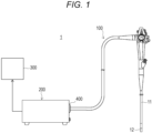
- FIG. 1 is a diagram illustrating an example of an overall external appearance of an endoscope system of the present embodiment
- Fig. 2 is a diagram illustrating a schematic internal configuration example of the endoscope system of the present embodiment.
- An endoscope system 1 includes an endoscope device (electronic scope) 100, a processor 200, and a monitor 300.
- a scope connector (which may hereinafter be simply referred to as a "connector") 400 including a connector circuit according to a feature of the present embodiment is provided at a processor-side end portion of the endoscope device 100.
- the endoscope device 100 includes an elongated tubular insertion portion 11 to be inserted into an object.
- the endoscope device 100 includes a light carrying bundle (LCB) 101 for guiding irradiation light from a light source device 201 that will be described later, a light distribution lens 102 provided at an emission end of the LCB 101, an imaging unit 103 that receives return light from an irradiated portion (observation site) via an objective lens (not illustrated), a driver signal processing circuit 105 that drives the imaging unit 103, and a first memory 106.
- LCB light carrying bundle
- the irradiation light from the light source device 201 enters the LCB 101 and propagates by repeating total reflection in the LCB 101.
- the irradiation light (illumination light) propagating in the LCB 101 is emitted from the emission end of the LCB 101 disposed in a distal tip portion 12 of the insertion portion 11 and irradiates the observation site through the light distribution lens 102.
- the return light from the irradiated portion forms an optical image at each pixel on a light receiving surface of the imaging unit 103 via the objective lens.
- the imaging unit 103 is disposed in the distal tip portion 12 of the insertion portion 11 and can use a complementary metal oxide semiconductor (CMOS) image sensor which is a rolling shutter type image sensor.
- CMOS complementary metal oxide semiconductor
- the imaging unit 103 accumulates optical images (return light from a living tissue) formed at each pixel on the light receiving surface, as electric charge corresponding to a light amount and generates and outputs image signals of R, G, and B.
- the imaging unit 103 is not limited to the CMOS image sensor and may be replaced with another type of imaging device as long as it is based on the rolling shutter type.
- a signal output from the imaging unit 103 is processed by a scope connector circuit 401 provided in the scope connector 400 as will be described later.
- the processor 200 is a device that integrally includes a signal processing device that processes a signal from the endoscope device 100 and a light source device that irradiates, via the endoscope device 100, a body cavity where natural light cannot reach.
- the signal processing device and the light source device may be provided separately.
- the processor 200 includes a light source device 201, a system controller 202, a photometry unit 203, a pre-stage signal processing circuit 205, a color conversion circuit 206, a post-stage signal processing circuit 207, and a second memory 208.
- the processor 200 may include an operation panel (not illustrated). There are various forms in a configuration of the operation panel. Examples of a specific configuration of the operation panel include a hardware key for each function mounted on a front surface of the processor 200, a touch panel type graphical user interface (GUI), a combination of the hardware key and the GUI, and the like. An operator (surgeon) can perform a mode switching operation that will be described later with the operation panel.
- GUI graphical user interface
- the photometry unit 203 acquires luminance information of an image signal obtained through imaging from a gain circuit included in the color conversion circuit 206, compares the acquired luminance information with a predetermined appropriate luminance value (for example, information of the appropriate luminance value may be stored in advance in an internal memory (not illustrated) of the photometry unit 203) and notifies the system controller 202 of a comparison result (whether a current luminance value is appropriate, higher, or lower).
- a predetermined appropriate luminance value for example, information of the appropriate luminance value may be stored in advance in an internal memory (not illustrated) of the photometry unit 203
- the system controller 202 executes various programs stored in a memory (not illustrated) and integrally controls the entire endoscope system 1.
- the system controller 202 controls operations and timings of various circuits in the processor 200 by using a control signal to perform processing suitable for the endoscope device 100 connected to the processor 200.
- the system controller 202 may be connected to the above-described operation panel.
- the system controller 202 receives the comparison result with the appropriate luminance value from the photometry unit 203, determines whether to maintain current exposure (exposure), whether to increase the exposure (including a level value to increase), or whether to decrease the exposure (including a level value to decrease) and outputs the comparison result to the light source device 201 as an exposure control signal.
- the system controller 202 changes each operation of the endoscope system 1 and parameters for each operation in accordance with an operator's instruction input from the operation panel. For example, when the operator selects an observation mode with the operation panel (mode switching operation), the system controller 202 outputs a mode selection signal for causing a light source corresponding to the observation mode to emit light to the light source device 201.
- the light source device 201 for example, a plurality of light emitting diodes (LEDs) that emit light with different wavelength bands may be used (see Fig. 3 ).
- the system controller 202 When the operator selects an observation mode (for example, a normal observation mode, a special light observation mode, a SatO2 mode, and the like) by operating a mode selection switch provided in the processor 200, for example, the system controller 202 generates a mode selection signal corresponding to the selected mode and supplies the mode selection signal to a light source control unit 2016 of the light source device 201 (see Fig. 3 ).
- the light source control unit 2016 determines a combination of LEDs that will emit light and their intensity and light amounts (for example, a combination, and the like, of light emitting LEDs corresponding to the mode selection signal are stored in advance in an internal memory (not illustrated)) and outputs a necessary LED control signal from the LEDs 2011 to 2015.
- the emitted light is synthesized by a cross prism to generate irradiation light (synthesized light).
- the endoscope device 100 and the processor 200 may perform data communication using a wired electric communication method or an optical wireless communication method.
- the scope connector 400 includes an LCB configuring a part of the LCB 101 continuing from the processor 200 to the endoscope device 100 and a scope connector circuit 401.
- the scope connector circuit 401 is provided in the scope connector 400 in the present embodiment, but is not necessarily provided in the scope connector 400.
- a circuit corresponding to the scope connector circuit 401 may be provided in a connector unit on the processor 200 side or inside the processor 200.
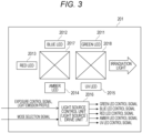
- Fig. 3 is a diagram illustrating an internal configuration example of the light source device 201 provided inside the processor 200, for example.
- the light source device 201 includes a green LED 2011 that emits green light, a blue LED 2012 that emits blue light, a red LED 2013 that emits red light, an amber LED 2014 that emits amber light, a UV LED 2015 that emits UV light, a light source control unit 2016 that controls light emission of the LEDs 2011 to 2015, and cross prisms 2017 and 2018.
- the light source control unit 2016 When the light source control unit 2016 receives the exposure control signal from the system controller 202, the light source control unit 2016 changes a light emission profile of each LED and performs exposure adjustment (light amount adjustment) by controlling a light emission period and an applied current value of each LED that is currently emitting light (a combination of LEDs that will emit light is determined depending on the observation mode) (see Fig. 12 that will be described later). For example, after changing the light emission profile by one step, the light source control unit 2016 determines whether to change the light emission profile again and perform exposure adjustment on the basis of an exposure control signal determined from a photometry result (a comparison result with the appropriate luminance value) from the photometry unit 203.
- the light source control unit 2016 determines a combination of LEDs that will emit light on the basis of a mode selection signal indicating an observation mode selected by the operator. In a light emission start stage, the light source control unit 2016 controls light emission of each LED on the basis of, for example, a predetermined light emission profile (a default light emission period and a drive current value), and thereafter, performs exposure adjustment as described above.
- a predetermined light emission profile a default light emission period and a drive current value
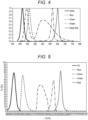
- Fig. 4 is a diagram illustrating spectra (wavelength characteristics) of the LEDs 2011 to 2015.
- Fig. 5 is a diagram illustrating characteristics of illumination light (light illuminating an observation site) generated by transmitting light from each LED through the cross prisms 2017 and 2018.
- a transmission wavelength band of the green LED 2011 is 540 nm to 575 nm, a peak wavelength is 550 nm, and a half-value width is 30 nm.
- a phosphor is provided in the green LED 2011, and the phosphor emits light in a transmission wavelength range of about 400 nm to 780 nm as illustrated in Fig. 4 .
- white light is substantially emitted by the green LED and the phosphor, this white light is an intermediate product, and as will be described later, the transmission wavelength band is narrowed by the cross prism 2018, and an observation site is irradiated with green light.
- a transmission wavelength band of the blue LED 2012 is 460 nm to 490 nm, a peak wavelength is 456 nm, and a half-value width is 21 nm.
- a transmission wavelength band of the red LED 2013 is 630 nm to 1000 nm, a peak wavelength is 650 nm, and a half-value width is 20 nm.
- a transmission wavelength band of the amber LED 2014 is 600 nm to 615 nm, a peak wavelength is 613 nm, and a half-value width is 19 nm.
- a transmission wavelength band of the UV LED 2015 is 385 nm to 425 nm, a peak wavelength is 405 nm, and a half-value width is 14 nm.
- the light (the white light as an intermediate product, the blue light, the red light, the amber light, or the UV light) emitted from each of the LEDs 2011 to 2015 including the green LED 2011 in which the phosphor is provided is transmitted through the cross prisms 2017 and 2018 to become light having the characteristics illustrated in Fig. 5 , and is applied to the observation site.
- the transmission wavelength band of the white light emitted from the green LED 2011 + the phosphor is limited by the cross prism 2018, so that the white light becomes green light with 520 nm to 595 nm.
- the blue light emitted from the blue LED 2012 becomes blue light with 440 nm to 500 nm by the cross prisms 2017 and 2018.
- the red light emitted from the red LED 2013 becomes red light with 620 nm to 630 nm by the cross prisms 2017 and 2018.
- the amber light emitted from the amber LED 2014 becomes amber light with 580 nm to 630 nm by the cross prisms 2017 and 2018.
- the UV light emitted from the UV LED 2015 becomes UV light with 380 nm to 450 nm by the cross prism 2018.
- the light source device 201 includes a plurality of LEDs
- not only wavelengths of light emitted from the LEDs 2011 to 2015 but also light distributions (light intensity distributions in respective directions) may be different (see Fig. 6 : configuration example of light source using LEDs having different light distributions), and a color or a light distribution of emitted light from each of the LEDs 2011 to 2015 may change.
- a forward voltage is lowered in order to lower the drive current value
- a drive current value rapidly decreases and the LED does not emit light, and thus there is a case where the drive current value cannot be greatly lowered.
- a correction table for correcting the linearity of the emitted light amount/current ratio is prepared in advance, and a drive current value for each of the LEDs 2011 to 2015 is determined by using the correction table.
- Fig. 7 is a graph illustrating an emitted light amount/current ratio of each LED. Fig. 7 illustrates a relationship between only two LEDs (the LED 1 and the LED 2) as an example, but the same applies to the case of using five LEDs 2011 to 2015 as described in the present embodiment. The relationship between the emitted light amount/current ratio of each LED as illustrated in Fig.
- a correction table having a reciprocal of the relationship between the emitted light amount/current ratios as a correction parameter is provided in advance (stored in a memory) as a correction value, and the light source control unit 2016 multiplies a correction parameter corresponding to a desired emitted light amount (target emitted light amount obtained through exposure adjustment) to calculate a corrected drive current value and drives each LED.
- Fig. 8 is a diagram illustrating a valid pixel region and an invalid pixel region of a rolling shutter type image sensor using a CMOS sensor as an example.
- the CMOS sensor includes a valid pixel region in which imaging can be performed and an invalid region in which imaging cannot be performed. A part (peripheral portion) of the valid pixel region is masked and is a region in which an image signal cannot be substantially acquired.
- various phenomena appear in a captured image. Note that, in the present embodiment, a period during which an image is not displayed on a screen is the global exposure period, but an idea of the present embodiment is not limited to this case.
- Fig. 9 is a diagram illustrating a state (example) of a general dimming control process and an observation image (example) acquired in each frame.
- Fig. 9 it can be seen that frames F1 and F2 are observed with an appropriate light amount (a photometry result is appropriate).
- a pseudo global exposure period between the frame F2 and a frame F3 since the endoscope distal tip is suddenly moved away from an object, an amount of irradiation light to the object is insufficient, and an observation image of the frame F3 is dark.
- a light amount at the time of acquiring the observation image of the frame F3 is dominated by a light amount from light emission (strong light emission: also referred to as main light emission) in the pseudo global exposure period between the previous frame (frame F2) and the current frame (frame F3).
- the dimming control is executed stepwise on the basis of the photometry result (light emission control (change of a light emission profile)) is performed stepwise according to the lapse of time (in order of the frames F4, F5, and F6), an appropriate light amount is determined (light amount increase control), and the object is irradiated with an appropriate amount of light.
- An observation image with an appropriate light amount can be acquired in the frame F5 after the endoscope distal tip is moved away from the object (after being moved away between F2 and F3).
- the observation image obtained in the frame F6 is the same as the observation image obtained in the frame F5.
- a light emission amount based on the latest light emission profile is not suitable for the next frame observation, and a light amount becomes excessive, and halation occurs in an image of the frame F7.
- a light emission amount (light emission profile) in the pseudo global period between the frame F6 and the frame F7 is determined on the basis of a photometry result of the image acquired in the frame F6 (a photometry result of the observation image of the frame F6 is appropriate). Only after the photometry result of the observation image of the frame F7 due to the excessive light emission amount is obtained, the excessive light emission amount due to sudden approach (including collision) to the object is corrected. That is, the light emission profile is changed for the first time in a pseudo global exposure period between the frame F7 and a frame F8 (even when a light amount is reduced, the light emission profile is changed stepwise in the same manner as when the light amount is increased.).
- the dimming control (amount reduction) is delayed by one frame.
- a light amount becomes excessive, and thus halation occurs in the observation image, and it is very difficult for the operator to perform observation.
- the present embodiment discloses a process of correcting the above disadvantage of general dimming control (delay of light emission profile change).
- Fig. 10 is a diagram illustrating a state (example) of a dimming control process according to Control Example 1 of the present embodiment and an observation image (example) acquired in each frame. Note that, in Fig. 10 , a distance between the endoscope distal tip and the object changes in a similar manner for comparison with the general dimming control process ( Fig. 9 ).
- Control Example 1 is a dimming control process of performing globally weak preliminary light emission (continuous light).
- a value (total value) of light emission time ⁇ light emission level of weak preliminary light emission (continuous light) in Control Example 1 is sufficiently smaller than a value of light emission time ⁇ light emission level of strong light emission in the pseudo global exposure period.
- the preliminary light emission is light emission at such an intensity that an undesirable event (for example, distortion or artifacts (such as scanning line noise)) caused by the rolling shutter can be ignored due to light emission (preliminary light emission), and such an intensity that light emission (preliminary light emission) can be recognized when the endoscope distal tip suddenly approaches the object.
- the value of the light emission time of the preliminary light emission ⁇ the light emission level may be 10% or less, preferably 2% or less, and more preferably 1% or less of the value of the light emission time of the strong light emission ⁇ the light emission level.
- a light amount at the time of acquiring the observation image of the frame F3 is dominated by a light amount from light emission (strong light emission) in the pseudo global exposure period between the previous frame (frame F2) and the current frame (frame F3).
- light emission (dimming control) following the change in the distance is performed (reflected) in the next frame (frame F4).
- the dimming control is executed stepwise on the basis of the photometry result (light emission control (change of a light emission profile)) is performed stepwise according to the lapse of time (in order of the frames F4, F5, and F6), an appropriate light amount is determined (light amount increase control), and the object is irradiated with an appropriate amount of light.
- An observation image with an appropriate light amount can be acquired in the frame F5 after the endoscope distal tip is moved away from the object (after being moved away between F2 and F3).
- the photometry result may be a photometric value of the central portion of the observation image or an average value of the photometric values of all the pixels.
- the light emission level is lowered stepwise so that the brightness changes more naturally for the operator, instead of being lowered rapidly. For example, as illustrated in Fig.
- the light emission amount in the pseudo global exposure period between the frame F6 and the frame F7 can be first reduced to a predetermined value, and the light emission amount can be further reduced to a predetermined value in the next pseudo global exposure period (between the frame F7 and the frame F8).
- a control amount (for example, a lowering width) for the light emission amount may be a constant value, or a light emission profile may be determined on the basis of the degree of excess with respect to an appropriate value for a photometry result.
- the dimming control process of Control Example 1 the weak preliminary light emission (continuous light) is performed in the pixel readout period (rolling shutter period), and thus, in response to changes of imaging conditions (for example, rapid approach of the endoscope distal tip to the object) in the pixel readout period, the dimming control can be performed one frame earlier than that in the general dimming control process, and the exposure level can be brought close to an appropriate exposure level (an appropriate photometry result can be acquired early).
- Fig. 11 is a diagram illustrating a state (example) of a dimming control process according to Control Example 2 of the present embodiment and an observation image (example) acquired in each frame. Note that, in Fig. 11 , a distance between the endoscope distal tip and the object changes in a similar manner for comparison with the general dimming control process ( Fig. 9 ).
- Control Example 2 is a dimming control process performed through globally weak preliminary light emission (pulse light).
- a value of light emission time ⁇ light emission level of weak preliminary light emission (pulse light) in Control Example 2 is sufficiently smaller than a value of light emission time ⁇ light emission level of strong light emission in the pseudo global exposure period, similarly to Control Example 1.
- the preliminary light emission is light emission at such an intensity that an undesirable event (for example, distortion or artifacts (such as scanning line noise)) caused by the rolling shutter can be ignored due to light emission (preliminary light emission), and such an intensity that light emission (preliminary light emission) can be recognized when the endoscope distal tip suddenly approaches the object.
- the value of the light emission time of the preliminary light emission ⁇ the light emission level may be 10% or less, preferably 2% or less, and more preferably 1% or less of the value of the light emission time of the strong light emission ⁇ the light emission level.
- the pulse light is used for weak preliminary light emission, but a frequency of the pulse is set to be higher by a predetermined value or more.
- a frequency of the pulse light is set such that an observation image does not have a stripe shape and the entire image becomes bright (whitish) when the endoscope distal tip approaches the object.
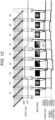
- Fig. 12 is a diagram illustrating a state (example) of a dimming control process according to Control Example 3 of the present embodiment and an observation image (example) acquired in each frame. Note that, in Fig. 12 , a distance between the endoscope distal tip and the object changes in a similar manner for comparison with the general dimming control process ( Fig. 9 ).
- Control Example 3 is a dimming control process of performing weak preliminary light emission (continuous light) only in a predetermined period of a pixel readout period (rolling shutter period) (for example, the last predetermined period of the rolling shutter period (or the predetermined period immediately before the next pseudo global exposure period)).
- second upper and lower lines in one frame is 2 ms, the remaining 14.6 ms is the valid line reading period.
- the above-described boundary is clearly seen.
- the operator can recognize the boundary although the boundary is inconspicuous. Therefore, it is necessary to make the boundary sufficiently smaller than the strong light emission period ⁇ the light emission level (for example, the light emission has such an intensity that an undesirable event (for example, distortion or artifacts) caused by the rolling shutter can be ignored due to the preliminary light emission, and such an intensity that light emission (preliminary light emission) can be recognized in a case where the endoscope distal tip approaches the object rapidly).
- the value of the light emission time ⁇ the light emission level of the preliminary light emission may be 10% or less, preferably 2% or less, and more preferably 1% or less of the value of the light emission time ⁇ the light emission level of the strong light emission.
- the preliminary light emission intensity can be made equal to (or larger than) the strong light emission intensity. That is, since the preliminary light emission period is short, as a result, a product of the preliminary light emission period and the preliminary light emission intensity tends to be small. However, for example, by instantaneously setting the preliminary light emission to 1000 times the strong light emission intensity, there is no problem even when the preliminary light emission is made larger than the strong light emission period ⁇ the light emission level.
- the light emission profile is controlled such that the total value (area value) of the preliminary light emission period ⁇ the preliminary light emission level becomes 10% or less, 2% or less, or 1% of the value (area value) of the light emission period ⁇ the light emission level of the strong light emission (main light emission).
- the preliminary light emission level may be extremely increased in relation to the line read in the observation image (not limited to the condition of 10% or less).
- a light amount at the time of acquiring the observation image of the frame F3 is dominated by a light amount from light emission (strong light emission) in the pseudo global exposure period between the previous frame (frame F2) and the current frame (frame F3).
- light emission (dimming control) following the change in the distance is performed (reflected) in the next frame (frame F4).
- the dimming control is executed stepwise on the basis of the photometry result (light emission control (change of a light emission profile)) is performed stepwise according to the lapse of time (in order of the frames F4, F5, and F6), an appropriate light amount is determined (light amount increase control), and the object is irradiated with an appropriate amount of light.
- An observation image with an appropriate light amount can be acquired in the frame F5 after the endoscope distal tip is moved away from the object (after being moved away between F2 and F3).
- a portion (region 1201) formed by pixels read in the period in which the preliminary light emission is performed is whiter (brighter) than other portions. That is, the influence of the excessive light amount due to the rapid approach of the endoscope distal tip to the object in the pixel readout period (rolling shutter period) for the frame F6 immediately appears in a part of the observation image.
- a dimming control process reflecting the excess light amount can be executed, and a process of lowering the strong light emission level in the pseudo global exposure period between the frame F6 and the frame F7 (adjustment to appropriate exposure) is performed.
- the light emission level is lowered stepwise so that the brightness changes more naturally for the operator, instead of being lowered rapidly.
- the light emission amount in the pseudo global exposure period between the frame F6 and the frame F7 can be first reduced to a predetermined value, and the light emission amount can be further reduced to a predetermined value in the next pseudo global exposure period (between the frame F7 and the frame F8).
- a control amount (for example, a lowering width) for the light emission amount may be a constant value, or a light emission profile may be determined on the basis of the degree of excess with respect to an appropriate value for a photometry result.
- the weak preliminary light emission (continuous light) is performed only in a predetermined period (for example, the last predetermined period of the rolling shutter period (or a predetermined period immediately before the next pseudo global exposure period)) of a part of the pixel readout period (rolling shutter period). Therefore, in response to the change (for example, rapid approach of the endoscope distal tip to the object) in the imaging condition in the pixel readout period, the dimming control can be performed one frame earlier than that in the general dimming control process, and the exposure level can be brought close to an appropriate exposure level (an appropriate photometry result can be acquired early).
- a predetermined period for example, the last predetermined period of the rolling shutter period (or a predetermined period immediately before the next pseudo global exposure period)
- the dimming control can be performed one frame earlier than that in the general dimming control process, and the exposure level can be brought close to an appropriate exposure level (an appropriate photometry result can be acquired early).
- Fig. 13 is a diagram illustrating a state (example) of a dimming control process according to Control Example 4 of the present embodiment and an observation image (example) acquired in each frame. Note that, in Fig. 13 , a distance between the endoscope distal tip and the object changes in a similar manner for comparison with the general dimming control process ( Fig. 9 ).
- Control Example 4 is a dimming control process of performing weak preliminary light emission (pulse light) only in a predetermined period (for example, the last predetermined period of the rolling shutter period (or the predetermined period immediately before the next pseudo global exposure period)) of the pixel readout period (rolling shutter period).
- the value of the light emission time ⁇ the light emission level of the weak preliminary light emission according to Control Example 4 is sufficiently smaller than the value of the light emission time ⁇ the light emission level of the strong light emission in the pseudo global exposure period, similarly to Control Examples 1 to 3.
- the preliminary light emission is light emission at such an intensity that an undesirable event (for example, distortion or artifacts (such as scanning line noise)) caused by the rolling shutter can be ignored due to light emission (preliminary light emission), and such an intensity that light emission (preliminary light emission) can be recognized when the endoscope distal tip suddenly approaches the object.
- the value of the light emission time of the preliminary light emission ⁇ the light emission level may be 10% or less, preferably 2% or less, and more preferably 1% or less of the value of the light emission time of the strong light emission ⁇ the light emission level.
- the pulse light is used for the weak preliminary light emission, but a frequency of the pulse is set to be higher by a predetermined value or more.
- the frequency of the pulse light is set such that a part (region 1301) of the observation image becomes bright (whitish) when the endoscope distal tip approaches the object.
- Fig. 14 is a flowchart for describing a dimming control process according to Control Examples 1 and 2 of the present embodiment.
- the process in each of the following steps will be mainly described with the system controller 202 as an operation subject, the present disclosure is not limited thereto, and a control unit (processor) that performs operation control and a calculation process may be separately provided and may be caused to perform the process.
- the light source control unit 2016 of the light source device 201 may have the functions of the system controller 202. Therefore, the dimming control process may be made a part of the entire operation of the endoscope system 1 or may be made a part of the operation of the light source device 201. In this case, the light source control unit 2016 is a main operation subject of the process in each step.
- the light source control unit 2016 receives a mode selection signal corresponding to an observation mode selected by an operator from the system controller 202 and corrects the linearity of an emitted light amount/current ratio of a light source for each light source (any combination of the green LED 2011 to the UV LED 2015) that is to emit light by using the correction table.
- the light source control unit 2016 drives each light source with a drive current after the linearity of the emitted light amount/current ratio is corrected to cause each light source to emit light to generate illumination light and irradiates the object with the illumination light.
- the profile of the strong light emission in the pseudo global exposure period at this time may be a predetermined value (default value), or may employ a light emission profile used in the last operation in the previous use of the endoscope.
- the light emission profile is determined such that the light emission period ⁇ the light emission level of weak preliminary light emission (continuous light or pulse light) in the pixel readout period (rolling shutter period) is 10% or less, 2% or less, or 1% or less of the light emission period (which may be shorter than the pseudo global exposure period) ⁇ the light emission level of strong light emission in the pseudo global period as described above (see Figs. 10 and 11 ).
- the image sensor (for example, a CMOS sensor) of the imaging unit 103 detects reflected light from the object generated by irradiating the object (observation site) with the illumination light and transmits a captured image signal to the processor 200 via the scope connector circuit 401.
- the system controller 202 starts to acquire image (each pixel) data for one frame via the photometry unit 203.
- the system controller 202 determines whether the acquired pixel (input pixel) is a valid pixel (see Fig. 8 : a pixel in the valid region of the CMOS sensor). In a case where the acquired pixel is a valid pixel (in a case of YES in step 1404), the process proceeds to step 1405. On the other hand, in a case where the acquired pixel is not a valid pixel (which is an invalid pixel or is a valid pixel but a masked pixel: in a case of NO in step 1404), the process proceeds to step 1406.
- the system controller 202 integrates photometric values (luminance values) of the valid pixels acquired from the photometry unit 203.
- the system controller 202 determines whether valid pixels for one frame have been acquired. In a case where the acquisition of the valid pixels for one frame has been completed (in a case of YES in step 1406), the process proceeds to step 1407. On the other hand, in a case where the acquisition of the valid pixels for one frame has not been completed yet (in a case of NO in step 1406), the process returns to step 1403.
- the system controller 202 compares the integrated value of the photometric values for one frame with a predetermined threshold value determined in advance, and determines whether the exposure is appropriate. In a case where it is determined that the photometric values are appropriate (in a case of YES in step 1407), the dimming control process is ended. On the other hand, in a case where it is determined that the photometric values are not appropriate (for example, an excessive light amount due to sudden approach to the object or an insufficient light amount due to movement away from the object) (in a case of NO in step 1407), the process proceeds to step 1408.
- the system controller 202 changes the light emission profile and transmits the light emission profile to the light source control unit 2016 of the light source device 201.
- the light emission profile may be changed to reduce or increase the predetermined light amount, or the profile may be determined on the basis of the degree of excess or deficiency with respect to the appropriate value.
- a change pattern for the light emission profile may be stored in advance (for example, tabulated) in a memory (not illustrated), and the system controller 202 may determine the light emission profile from a deviation amount (for example, 3 dB excess , a light emission pattern 1, 6 dB excess , a light emission pattern 2, 3 dB deficiency , a light emission pattern 3, ⁇ , and the like) between the measured photometric value and the appropriate photometric value.
- a deviation amount for example, 3 dB excess , a light emission pattern 1, 6 dB excess , a light emission pattern 2, 3 dB deficiency , a light emission pattern 3, ⁇ , and the like
- Fig. 15 is a flowchart for describing a dimming control process according to Control Examples 3 and 4 of the present embodiment.
- the process in each of the following steps will be mainly described with the system controller 202 as an operation subject, the present disclosure is not limited thereto, and a control unit (processor) that performs operation control and a calculation process may be separately provided and may be caused to perform the process.
- the light source control unit 2016 of the light source device 201 may have the functions of the system controller 202. Therefore, the dimming control process may be made a part of the entire operation of the endoscope system 1 or may be made a part of the operation of the light source device 201. In this case, the light source control unit 2016 is a main operation subject of the process in each step.
- the light source control unit 2016 receives a mode selection signal corresponding to an observation mode selected by an operator from the system controller 202 and corrects the linearity of an emitted light amount/current ratio of a light source for each light source (any combination of the green LED 2011 to the UV LED 2015) that is to emit light by using the correction table.
- the light source control unit 2016 drives each light source with a drive current after the linearity of the emitted light amount/current ratio is corrected to cause each light source to emit light to generate illumination light and irradiates the object with the illumination light.
- the profile of the strong light emission in the pseudo global exposure period at this time may be a predetermined value (default value), or may employ a light emission profile used in the last operation in the previous use of the endoscope.
- weak preliminary light emission continuous light or pulse light
- the light emission profile is determined such that the light emission period (which may be shorter than the pseudo global exposure period) ⁇ the light emission level of the weak preliminary light emission is 10% or less, 2% or less, or 1% or less of the light emission period ⁇ the light emission level of the strong light emission in the pseudo global period (see Figs. 10 and 11 ).
- the image sensor (for example, a CMOS sensor) of the imaging unit 103 detects reflected light from the object generated by irradiating the object (observation site) with the illumination light and transmits a captured image signal to the processor 200 via the scope connector circuit 401.
- the system controller 202 starts to acquire image (each pixel) data for one frame via the photometry unit 203.
- the system controller 202 determines whether the acquired pixel (input pixel) is a valid pixel (see Fig. 8 : a pixel in the valid region of the CMOS sensor). In a case where the acquired pixel is a valid pixel (in a case of YES in step 1504), the process proceeds to step 1505. On the other hand, when the acquired pixel is not a valid pixel (which is an invalid pixel or is a valid pixel but a masked pixel: in a case of NO in step 1504), the process proceeds to step 1509.
- the system controller 202 determines whether the acquired (input) valid pixel is a pixel of the preliminary light emission line.
- a readout line number and an irradiation timing of weak preliminary light emission in the frame (image) are determined in advance. For example, information regarding a line number and an irradiation body mig is stored in an internal memory of the system controller 202 or a memory (not illustrated). Thus, the system controller 202 can determine in which line weak preliminary light emission is performed.
- step 1506 In a case where it is determined that the acquired pixel is a pixel configuring the preliminary light emission line (in a case of YES in step 1505), the process proceeds to step 1506. On the other hand, in a case where it is determined that the acquired pixel is not related to the preliminary light emission line (in a case of NO in step 1505), the process proceeds to step 1507.
- the system controller 202 integrates the luminance values of the pixels in the line where weak preliminary light emission is performed to obtain preliminary light emission photometric values (since the preliminary light emission line is also affected by the strong light emission in the pseudo global exposure period, a photometric value is obtained through the strong light emission + the weak preliminary light emission). That is, the luminance value of each pixel configuring the line related to the preliminary light emission is integrated pixel by pixel, and the preliminary light emission photometric value for one frame is finally calculated.
- the preliminary light emission photometric value for one frame is stored in an internal memory of the system controller 202 or a memory (not illustrated).
- the system controller 202 integrates luminance values of input pixels other than the preliminary light emission line, and calculates a normal light emission photometric value through strong light emission in the pseudo global exposure period. That is, the luminance value of each pixel configuring the line other than the preliminary light emission line is integrated pixel by pixel, and a normal light emission photometric value for one frame is finally calculated. Note that the normal light emission photometric value for one frame is stored in an internal memory of the system controller 202 or a memory (not illustrated).
- the system controller 202 adds the preliminary light emission photometric value calculated in step 1506 and the normal light emission photometric value calculated in step 1507 to calculate a photometric value (provisional) for the entire one frame.
- the system controller 202 determines whether valid pixels for one frame have been acquired. In a case where the acquisition of the valid pixels for one frame has been completed (in a case of YES in step 1509), the process proceeds to step 1510. On the other hand, in a case where the acquisition of the valid pixels for one frame has not been completed yet (in a case of NO in step 1509), the processing returns to step 1503. In a case of YES in step 1509, the photometric value (provisional) for the entire one frame obtained in step 1508 is a photometric value (confirmation) for the entire one frame.
- the system controller 202 compares the photometric value (confirmation) for the entire one frame with a predetermined threshold value (overall photometric threshold value), and determines whether or not the photometric value is appropriate.
- a predetermined threshold value overall photometric threshold value
- the overall photometric threshold value may be a value having a predetermined width (range).
- step 1510 In a case where it is determined that the photometric value (confirmation) of the entire one frame is appropriate (in a case of YES in step 1510), the process proceeds to step 1511. On the other hand, when it is determined that the photometric value (confirmation) of the entire one frame is not appropriate (in a case of NO in step 1510), the process proceeds to step 1512.
- the system controller 202 acquires the preliminary light emission photometric value in the frame, compares the preliminary light emission photometric value with a predetermined threshold value (preliminary light emission threshold value), and determines whether or not the preliminary light emission photometric value is appropriate.
- a predetermined threshold value preliminary light emission threshold value
- the preliminary light emission threshold value may be a value having a predetermined width (range), similarly to the overall photometric threshold value.
- step 1511 In a case where it is determined that the preliminary light emission photometric value is appropriate (in a case of YES in step 1511), the dimming control process is ended. On the other hand, in a case where it is determined that the preliminary light emission photometric value is not appropriate (in a case of NO in step 1511), the process proceeds to step 1512.
- the system controller 202 changes the light emission profile and transmits the light emission profile to the light source control unit 2016 of the light source device 201.
- the light emission profile may be changed to reduce or increase the predetermined light amount, or the profile may be determined on the basis of the degree of excess or deficiency with respect to the appropriate value.
- a change pattern for the light emission profile may be stored in advance (for example, tabulated) in a memory (not illustrated), and the system controller 202 may determine the light emission profile from a deviation amount (for example, 3 dB excess ⁇ the light emission pattern 1, 6 dB excess ⁇ the light emission pattern 2, 3 dB deficiency ⁇ the light emission pattern 3, ⁇ , and the like) between the measured photometric value and the appropriate photometric value.
- a deviation amount for example, 3 dB excess ⁇ the light emission pattern 1, 6 dB excess ⁇ the light emission pattern 2, 3 dB deficiency ⁇ the light emission pattern 3, ⁇ , and the like
- the light emission level (and/or the light emission period) of the strong light emission in the pseudo global exposure period may be increased or decreased stepwise every frame time (for example, 1/30 seconds) (see F6 ⁇ F7 ⁇ F8 in Figs. 12 and 13 ). By doing so, it is possible to avoid a sudden change in brightness, and thus, it is possible to acquire a natural observation image.
- an exposure component (a luminance component due to weak preliminary light emission) in a case where the endoscope distal tip (image sensor) suddenly approaches an object during the rolling shutter period is added to a photometry result.
- a luminance component due to strong light emission (main light emission) in the pseudo global exposure period is overwhelmingly stronger than a luminance component due to weak preliminary light emission in the rolling shutter period
- the luminance component due to the strong light emission is dominant in observation image formation (here, the reason why the light emission profile of the strong light emission is determined is that a distance between the image sensor and the object is longer than that at the time of the sudden approach and is thus appropriate).
- the entire observation image (Control Examples 1 and 2) or a part of the observation image (a lower portion of the observation image: Control Examples 3 and 4) becomes whitish, and a photometry result due to weak preliminary light emission immediately appears in the observation image, and it is possible to immediately detect that a light amount is excessive. Therefore, according to the dimming control process of the present embodiment, the light amount control can be executed in response to a change during the rolling shutter period (pixel readout period) quickly.
- the weak preliminary light emission is controlled to be 10% or less (preferably 2% or less, and more preferably 1% or less) of the main light emission with respect to the value of the light emission period ⁇ the light emission level.
- a light source device that generates illumination light to be applied to an object, the light source device including:
- the light source device in which a total value of a light emission period ⁇ a light emission level of the preliminary light emission is sufficiently smaller than a value of a light emission period ⁇ a light emission level of the main light emission such that noise caused by a rolling shutter of the image sensor is ignorable.
- the light source device in which the control unit controls a total value of a light emission period ⁇ a light emission level of the preliminary light emission to be 10% or less of a value of a light emission period ⁇ a light emission level of the main light emission.
- control unit controls the light emission profile such that the preliminary light emission is configured by using continuous light or pulse light over the entire pixel readout period.
- control unit compares a photometric value for one frame of an observation image of the object with a first threshold value, and determines whether or not to change the light emission profile.
- control unit changes the light emission profile such that the light emission level of the main light emission is lowered stepwise over a plurality of frames in a case where the photometric value is greater than the first threshold value and a light amount is excessive.
- control unit controls the light emission profile such that the preliminary light emission is performed by using continuous light or pulse light in the pixel readout period of pixels configuring 25% or less of a lower portion of an observation image of the object.
- control unit controls a total value of a light emission period ⁇ a light emission level of the preliminary light emission to be 10% or less of a value of a light emission period ⁇ a light emission level of the main light emission.
- control unit controls the light emission profile such that the preliminary light emission is performed by using continuous light or pulse light during the pixel readout period of pixels configuring a predetermined number of lines of an observation image of the object.
- control unit controls the light emission profile such that the preliminary light emission is performed by using the continuous light or the pulse light during the pixel readout period of pixels configuring a final predetermined number of lines of the observation image.
- control unit compares a photometric value based on the preliminary light emission in one frame of the observation image of the object with a second threshold value, and determines whether or not to change the light emission profile.
- control unit changes the light emission profile such that the light emission level of the main light emission is lowered stepwise over a plurality of frames in a case where the photometric value is greater than the second threshold value and a light amount is excessive.
- An endoscope system in which an endoscope is inserted into an observation target and an image of an object is acquired including:
- the endoscope system in which a total value of a light emission period ⁇ a light emission level of the preliminary light emission is sufficiently smaller than a value of a light emission period ⁇ a light emission level of the main light emission such that noise caused by a rolling shutter of the image sensor is ignorable.
- the endoscope system in which the main control unit controls a total value of a light emission period ⁇ a light emission level of the preliminary light emission to be 10% or less of a value of a light emission period ⁇ a light emission level of the main light emission.
- the endoscope system according to any one of the specified matters 13 to 15, in which the main control unit controls the light emission profile such that the preliminary light emission is configured by using continuous light or pulse light over the entire pixel readout period.
- the endoscope system according to any one of the specified matters 13 to 16, in which the main control unit compares a photometric value for one frame of an observation image of the object with a first threshold value, and determines whether or not to change the light emission profile.
- the endoscope system in which the main control unit changes the light emission profile such that the light emission level of the main light emission is lowered stepwise over a plurality of frames in a case where the photometric value is greater than the first threshold value and a light amount is excessive.
- the endoscope system in which the main control unit controls the light emission profile such that the preliminary light emission is performed by using continuous light or pulse light in the pixel readout period of pixels configuring 25% or less of a lower portion of an observation image of the object.
- the endoscope system in which the main control unit controls a total value of a light emission period ⁇ a light emission level of the preliminary light emission to be 10% or less of a value of a light emission period ⁇ a light emission level of the main light emission.
- the endoscope system in which the main control unit controls the light emission profile such that the preliminary light emission is performed by using continuous light or pulse light during the pixel readout period of pixels configuring a predetermined number of lines of an observation image of the object.
- the endoscope system in which the main control unit controls the light emission profile such that the preliminary light emission is performed by using the continuous light or the pulse light during the pixel readout period of pixels configuring a final predetermined number of lines of the observation image.
- the endoscope system according to any one of the specified matters 19 to 22, in which the main control unit compares a photometric value based on the preliminary light emission in one frame of the observation image of the object with a second threshold value, and determines whether or not to change the light emission profile.
- the endoscope system in which the main control unit changes the light emission profile such that the light emission level of the main light emission is lowered stepwise over a plurality of frames in a case where the photometric value is greater than the second threshold value and a light amount is excessive.
- the above-described functions of the present embodiment can also be realized by software program codes.
- a storage medium recording the program codes is provided to a system or a device, and a computer (or CPU, MPU, etc.) of the system or the device reads the program codes stored in the storage medium.
- the program codes read from the storage medium realize the functions of the above-described embodiments, and the program codes and the storage medium storing the program codes are configured to achieve the present disclosure.
- Examples of the storage medium applicable for supplying such program codes include a flexible disk, CD-ROM, DVD-ROM, hard disk, optical disk, magneto-optical disk, CD-R, magnetic tape, nonvolatile memory card, or ROM.
- OS operating system
- the program codes read from the storage medium are first written in the memory on the computer, and thereafter the computer CPU or the like performs some or all of the actual processes on the basis of the instruction of the program codes, so as to realize the functions of the above-described embodiments through the processes.
- the program codes of software realizing the functions of the present embodiment may be distributed via a network and stored in storage means such as a hard disk or a memory of a system or a device or a storage medium such as a CD-RW or a CD-R, and a computer (or a CPU or an MPU) of the system or the device may read and execute the program codes stored in the storage means or the storage medium at the time of use.
- storage means such as a hard disk or a memory of a system or a device or a storage medium such as a CD-RW or a CD-R
- a computer or a CPU or an MPU
- control lines and information lines are considered to be necessary for explanation, and these are not necessarily illustrating control lines and information lines associated with the product. All the constituents may be connected to each other.
Landscapes
- Health & Medical Sciences (AREA)
- Life Sciences & Earth Sciences (AREA)
- Surgery (AREA)
- Engineering & Computer Science (AREA)
- Physics & Mathematics (AREA)
- Optics & Photonics (AREA)
- Heart & Thoracic Surgery (AREA)
- Animal Behavior & Ethology (AREA)
- Pathology (AREA)
- Radiology & Medical Imaging (AREA)
- Biophysics (AREA)
- Biomedical Technology (AREA)
- Veterinary Medicine (AREA)
- Medical Informatics (AREA)
- Molecular Biology (AREA)
- Nuclear Medicine, Radiotherapy & Molecular Imaging (AREA)
- General Health & Medical Sciences (AREA)
- Public Health (AREA)
- Signal Processing (AREA)
- Multimedia (AREA)
- Microelectronics & Electronic Packaging (AREA)
- Astronomy & Astrophysics (AREA)
- General Physics & Mathematics (AREA)
- Endoscopes (AREA)
- Instruments For Viewing The Inside Of Hollow Bodies (AREA)
- Studio Devices (AREA)
Abstract
Description
- The present disclosure relates to a light source device and an endoscope system.
- In a normal endoscope device equipped with a rolling shutter type image sensor, a light source is turned off in a valid pixel readout period (rolling shutter period) of the image sensor, and the light source is turned on in other periods (pseudo global exposure period) (pulse light emission control is performed), thereby executing pseudo global exposure and avoiding the occurrence of an undesirable phenomenon caused by the rolling shutter, for example, distortion or artifacts.
- On the other hand, when the light source is completely turned off during the rolling shutter period, a light amount becomes insufficient depending on an object (observation target site), and a favorable image cannot be acquired. For example,
Patent Literatures 1 to 3, and the like, disclose light source control in which a part of the rolling shutter period is included in a pulse light emission period in order to solve having an insufficient light amount. -
- Patent Literature 1:
JP 2018-182580 A - Patent Literature 2:
JP 5379932 B1 - Patent Literature 3:
JP 6239220 B1 - However, when the light source control as described in
Patent Literatures 1 to 3 is executed, brightness unevenness, lateral stripes, and the like, of a screen occur due to an exposure period difference for each line in adjacent frames. There is a problem that the brightness unevenness and the lateral stripes move up and down on a display screen due to a change in the pulse light emission period for each frame and obstruct viewing. In a case where offset light emission is performed during the rolling shutter period in order to solve the insufficient light amount, when the offset light emission becomes strong to some extent, an unnatural image such as a long-time exposure image and a high-speed exposure image subjected to double exposure is generated (occurrence of artifacts and scanning line noise (distortion)). - In the techniques according to
Patent Literatures 1 to 3, an event that has changed during the turn-off period (rolling shutter period) is not observed in the readout in that period, and can be observed only in the next readout frame exposed by the next pulse light emission. Thus, there is a risk that perforation or halation will occur in an image when a distal tip of an endoscope suddenly approaches an object. In order to suppress the risk of occurrence of such perforation or halation, it is necessary to promptly ascertain a change in brightness of a screen due to a sudden approach and immediately reflect the change in brightness in light amount control. - The present disclosure has been made in view of such a situation, and proposes a technique capable of executing light amount control quickly in response to a change during a rolling shutter period (pixel readout period) while avoiding the occurrence of distortion and artifacts caused by a rolling shutter of an image sensor.
- In order to solve the above problem, according to the present embodiment, there is provided a light source device that generates illumination light to be applied to an object, the light source device including a plurality of semiconductor light emitting elements that emit pieces of light having different wavelength bands; and a control unit that controls a light emission profile of the plurality of semiconductor light emitting elements and drives the plurality of semiconductor light emitting elements, in which the control unit controls the light emission profile of the plurality of semiconductor light emitting elements such that main light emission is performed in a pseudo global exposure period of an image sensor and preliminary light emission is performed in at least a part of a pixel readout period of the image sensor, and a light emission level of the preliminary light emission is lower than a light emission level of the main light emission.
- According to the present embodiment, there is provided an endoscope system in which an endoscope is inserted into an observation target and an image of an object is acquired, the endoscope system including a plurality of semiconductor light emitting elements that emit pieces of light having different wavelength bands; an image sensor that irradiates the object with illumination light and detects reflected light from the object to generate an image signal; a processor that processes the image signal to generate the image of the object and displays the image on a monitor; a main control unit that generates a control signal for controlling a light emission profile of the plurality of semiconductor light emitting elements on the basis of the image signal; and a light source control unit that receives the control signal from the main control unit and drives the plurality of semiconductor light emitting elements with a drive signal according to the light emission profile, in which the main control unit controls the light emission profile of the plurality of semiconductor light emitting elements such that main light emission is performed in a pseudo global exposure period of the image sensor and preliminary light emission is performed in at least a part of a pixel readout period of the image sensor, and a light emission level of the preliminary light emission is lower than a light emission level of the main light emission.
- Features related to the present disclosure will become apparent from the description of the present specification and the accompanying drawings. The present disclosure is achieved and implemented by elements and combinations of various elements and by modes of the following detailed description and the appended claims.
- It is to be understood that the description in this specification is merely exemplary and is not intended to limit the significance of the claims or the application in any way.
- According to the present disclosure, it is possible to execute light amount control quickly in response to a change during a rolling shutter period (pixel readout period) while avoiding the occurrence of distortion and artifacts caused by a rolling shutter of an image sensor.
-
-
Fig. 1 is a diagram illustrating an overall external appearance example of an endoscope system according to the present embodiment. -
Fig. 2 is a diagram illustrating a schematic internal configuration example of the endoscope system according to the present embodiment. -
Fig. 3 is a diagram illustrating an internal configuration example of alight source device 201 provided inside aprocessor 200. -
Fig. 4 is a diagram illustrating spectra (wavelength characteristics) ofLEDs 2011 to 2015.Fig. 5 is a diagram illustrating characteristics of illumination light (light illuminating an observation site) generated by transmitting light from each LED throughcross prisms -
Fig. 6 is a diagram illustrating a configuration example of a light source using LEDs having different light distributions. -
Fig. 7 is a graph of an emitted light amount/current ratio of each LED. -
Fig. 8 is a diagram illustrating a valid pixel region and an invalid region of a rolling shutter type image sensor using a CMOS sensor as an example. -
Fig. 9 is a diagram illustrating a state (example) of a general dimming control process and an observation image (example) acquired in each frame. -
Fig. 10 is a diagram illustrating a state (example) of a dimming control process according to Control Example 1 of the present embodiment and an observation image (example) acquired in each frame. -
Fig. 11 is a diagram illustrating a state (example) of a dimming control process according to Control Example 2 of the present embodiment and an observation image (example) acquired in each frame. -
Fig. 12 is a diagram illustrating a state (example) of a dimming control process according to Control Example 3 of the present embodiment and an observation image (example) acquired in each frame. -
Fig. 13 is a diagram illustrating a state (example) of a dimming control process according to Control Example 4 of the present embodiment and an observation image (example) acquired in each frame. -
Fig. 14 is a flowchart for describing a dimming control process according to Control Examples 1 and 2 of the present embodiment. -
Fig. 15 is a flowchart for describing a dimming control process according to Control Examples 3 and 4 of the present embodiment. - Hereinafter, embodiments of the present disclosure will be described with reference to the drawings. In the following description, an endoscope system will be described as an embodiment of the present disclosure.
- An observation target site in the endoscope system is, for example, respiratory organs or digestive organs. Examples of the respiratory organs include the lungs, the bronchus, the ears, the nose, and the throat. Examples of the digestive organs include the large intestine, the small intestine, the stomach, the esophagus, the duodenum, the uterus, and the bladder. In a case of observing the target sites as described above, it is more valid to utilize an image in which a specific biological structure is emphasized.
-
Fig. 1 is a diagram illustrating an example of an overall external appearance of an endoscope system of the present embodiment, andFig. 2 is a diagram illustrating a schematic internal configuration example of the endoscope system of the present embodiment. Anendoscope system 1 includes an endoscope device (electronic scope) 100, aprocessor 200, and amonitor 300. Note that a scope connector (which may hereinafter be simply referred to as a "connector") 400 including a connector circuit according to a feature of the present embodiment is provided at a processor-side end portion of theendoscope device 100. - The
endoscope device 100 includes an elongatedtubular insertion portion 11 to be inserted into an object. Theendoscope device 100 includes a light carrying bundle (LCB) 101 for guiding irradiation light from alight source device 201 that will be described later, alight distribution lens 102 provided at an emission end of theLCB 101, animaging unit 103 that receives return light from an irradiated portion (observation site) via an objective lens (not illustrated), a driver signal processing circuit 105 that drives theimaging unit 103, and a first memory 106. - The irradiation light from the
light source device 201 enters the LCB 101 and propagates by repeating total reflection in the LCB 101. The irradiation light (illumination light) propagating in theLCB 101 is emitted from the emission end of theLCB 101 disposed in adistal tip portion 12 of theinsertion portion 11 and irradiates the observation site through thelight distribution lens 102. The return light from the irradiated portion forms an optical image at each pixel on a light receiving surface of theimaging unit 103 via the objective lens. - The
imaging unit 103 is disposed in thedistal tip portion 12 of theinsertion portion 11 and can use a complementary metal oxide semiconductor (CMOS) image sensor which is a rolling shutter type image sensor. Theimaging unit 103 accumulates optical images (return light from a living tissue) formed at each pixel on the light receiving surface, as electric charge corresponding to a light amount and generates and outputs image signals of R, G, and B. Note that theimaging unit 103 is not limited to the CMOS image sensor and may be replaced with another type of imaging device as long as it is based on the rolling shutter type. A signal output from theimaging unit 103 is processed by ascope connector circuit 401 provided in thescope connector 400 as will be described later. - The
processor 200 is a device that integrally includes a signal processing device that processes a signal from theendoscope device 100 and a light source device that irradiates, via theendoscope device 100, a body cavity where natural light cannot reach. In another embodiment, the signal processing device and the light source device may be provided separately. Theprocessor 200 includes alight source device 201, asystem controller 202, aphotometry unit 203, a pre-stagesignal processing circuit 205, acolor conversion circuit 206, a post-stagesignal processing circuit 207, and asecond memory 208. - The
processor 200 may include an operation panel (not illustrated). There are various forms in a configuration of the operation panel. Examples of a specific configuration of the operation panel include a hardware key for each function mounted on a front surface of theprocessor 200, a touch panel type graphical user interface (GUI), a combination of the hardware key and the GUI, and the like. An operator (surgeon) can perform a mode switching operation that will be described later with the operation panel. - The
photometry unit 203 acquires luminance information of an image signal obtained through imaging from a gain circuit included in thecolor conversion circuit 206, compares the acquired luminance information with a predetermined appropriate luminance value (for example, information of the appropriate luminance value may be stored in advance in an internal memory (not illustrated) of the photometry unit 203) and notifies thesystem controller 202 of a comparison result (whether a current luminance value is appropriate, higher, or lower). - The
system controller 202 executes various programs stored in a memory (not illustrated) and integrally controls theentire endoscope system 1. Thesystem controller 202 controls operations and timings of various circuits in theprocessor 200 by using a control signal to perform processing suitable for theendoscope device 100 connected to theprocessor 200. Thesystem controller 202 may be connected to the above-described operation panel. - The
system controller 202 receives the comparison result with the appropriate luminance value from thephotometry unit 203, determines whether to maintain current exposure (exposure), whether to increase the exposure (including a level value to increase), or whether to decrease the exposure (including a level value to decrease) and outputs the comparison result to thelight source device 201 as an exposure control signal. - The
system controller 202 changes each operation of theendoscope system 1 and parameters for each operation in accordance with an operator's instruction input from the operation panel. For example, when the operator selects an observation mode with the operation panel (mode switching operation), thesystem controller 202 outputs a mode selection signal for causing a light source corresponding to the observation mode to emit light to thelight source device 201. As will be described later, as thelight source device 201, for example, a plurality of light emitting diodes (LEDs) that emit light with different wavelength bands may be used (seeFig. 3 ). When the operator selects an observation mode (for example, a normal observation mode, a special light observation mode, a SatO2 mode, and the like) by operating a mode selection switch provided in theprocessor 200, for example, thesystem controller 202 generates a mode selection signal corresponding to the selected mode and supplies the mode selection signal to a lightsource control unit 2016 of the light source device 201 (seeFig. 3 ). On the basis of the mode selection signal, the lightsource control unit 2016 determines a combination of LEDs that will emit light and their intensity and light amounts (for example, a combination, and the like, of light emitting LEDs corresponding to the mode selection signal are stored in advance in an internal memory (not illustrated)) and outputs a necessary LED control signal from theLEDs 2011 to 2015. When each of theLEDs 2011 to 2015 emits light of each wavelength band based on the LED control signal supplied from the lightsource control unit 2016, the emitted light is synthesized by a cross prism to generate irradiation light (synthesized light). - The
endoscope device 100 and theprocessor 200 may perform data communication using a wired electric communication method or an optical wireless communication method. - As illustrated in
Fig. 2 , theendoscope device 100 and theprocessor 200 are connected via thescope connector 400. Thescope connector 400 includes an LCB configuring a part of theLCB 101 continuing from theprocessor 200 to theendoscope device 100 and ascope connector circuit 401. Thescope connector circuit 401 is provided in thescope connector 400 in the present embodiment, but is not necessarily provided in thescope connector 400. For example, a circuit corresponding to thescope connector circuit 401 may be provided in a connector unit on theprocessor 200 side or inside theprocessor 200. -
Fig. 3 is a diagram illustrating an internal configuration example of thelight source device 201 provided inside theprocessor 200, for example. - The
light source device 201 includes agreen LED 2011 that emits green light, ablue LED 2012 that emits blue light, ared LED 2013 that emits red light, anamber LED 2014 that emits amber light, aUV LED 2015 that emits UV light, a lightsource control unit 2016 that controls light emission of theLEDs 2011 to 2015, and crossprisms - When the light
source control unit 2016 receives the exposure control signal from thesystem controller 202, the lightsource control unit 2016 changes a light emission profile of each LED and performs exposure adjustment (light amount adjustment) by controlling a light emission period and an applied current value of each LED that is currently emitting light (a combination of LEDs that will emit light is determined depending on the observation mode) (seeFig. 12 that will be described later). For example, after changing the light emission profile by one step, the lightsource control unit 2016 determines whether to change the light emission profile again and perform exposure adjustment on the basis of an exposure control signal determined from a photometry result (a comparison result with the appropriate luminance value) from thephotometry unit 203. - The light
source control unit 2016 determines a combination of LEDs that will emit light on the basis of a mode selection signal indicating an observation mode selected by the operator. In a light emission start stage, the lightsource control unit 2016 controls light emission of each LED on the basis of, for example, a predetermined light emission profile (a default light emission period and a drive current value), and thereafter, performs exposure adjustment as described above. -
Fig. 4 is a diagram illustrating spectra (wavelength characteristics) of theLEDs 2011 to 2015.Fig. 5 is a diagram illustrating characteristics of illumination light (light illuminating an observation site) generated by transmitting light from each LED through thecross prisms - A transmission wavelength band of the
green LED 2011 is 540 nm to 575 nm, a peak wavelength is 550 nm, and a half-value width is 30 nm. A phosphor is provided in thegreen LED 2011, and the phosphor emits light in a transmission wavelength range of about 400 nm to 780 nm as illustrated inFig. 4 . In other words, although white light is substantially emitted by the green LED and the phosphor, this white light is an intermediate product, and as will be described later, the transmission wavelength band is narrowed by thecross prism 2018, and an observation site is irradiated with green light. A transmission wavelength band of theblue LED 2012 is 460 nm to 490 nm, a peak wavelength is 456 nm, and a half-value width is 21 nm. A transmission wavelength band of thered LED 2013 is 630 nm to 1000 nm, a peak wavelength is 650 nm, and a half-value width is 20 nm. A transmission wavelength band of theamber LED 2014 is 600 nm to 615 nm, a peak wavelength is 613 nm, and a half-value width is 19 nm. A transmission wavelength band of theUV LED 2015 is 385 nm to 425 nm, a peak wavelength is 405 nm, and a half-value width is 14 nm. - The light (the white light as an intermediate product, the blue light, the red light, the amber light, or the UV light) emitted from each of the
LEDs 2011 to 2015 including thegreen LED 2011 in which the phosphor is provided is transmitted through thecross prisms Fig. 5 , and is applied to the observation site. Specifically, the transmission wavelength band of the white light emitted from thegreen LED 2011 + the phosphor is limited by thecross prism 2018, so that the white light becomes green light with 520 nm to 595 nm. The blue light emitted from theblue LED 2012 becomes blue light with 440 nm to 500 nm by thecross prisms red LED 2013 becomes red light with 620 nm to 630 nm by thecross prisms amber LED 2014 becomes amber light with 580 nm to 630 nm by thecross prisms UV LED 2015 becomes UV light with 380 nm to 450 nm by thecross prism 2018. - In a case where the
light source device 201 includes a plurality of LEDs, not only wavelengths of light emitted from theLEDs 2011 to 2015 but also light distributions (light intensity distributions in respective directions) may be different (seeFig. 6 : configuration example of light source using LEDs having different light distributions), and a color or a light distribution of emitted light from each of theLEDs 2011 to 2015 may change. Depending on the type of the LED, when a forward voltage is lowered in order to lower the drive current value, a drive current value rapidly decreases and the LED does not emit light, and thus there is a case where the drive current value cannot be greatly lowered. In order to cope with such a situation, it is necessary to dynamically correct a difference between linearities of the emitted light amount/current ratios of therespective LEDs 2011 to 2015 in accordance with drive current control for theLEDs 2011 to 2015. - However, a process of dynamically correcting the difference in linearity is complicated, and thus it is preferable to determine a drive current value in advance such that there is no difference in linearity. Therefore, in the present embodiment, a correction table for correcting the linearity of the emitted light amount/current ratio is prepared in advance, and a drive current value for each of the
LEDs 2011 to 2015 is determined by using the correction table.Fig. 7 is a graph illustrating an emitted light amount/current ratio of each LED.Fig. 7 illustrates a relationship between only two LEDs (theLED 1 and the LED 2) as an example, but the same applies to the case of using fiveLEDs 2011 to 2015 as described in the present embodiment. The relationship between the emitted light amount/current ratio of each LED as illustrated inFig. 7 may be acquired by measuring each LED in advance. Thus, a correction table having a reciprocal of the relationship between the emitted light amount/current ratios as a correction parameter is provided in advance (stored in a memory) as a correction value, and the lightsource control unit 2016 multiplies a correction parameter corresponding to a desired emitted light amount (target emitted light amount obtained through exposure adjustment) to calculate a corrected drive current value and drives each LED. This makes it possible to appropriately control the linearity of the emitted light amount/current ratio even in a case where wavelengths or light distributions of emitted light of the respective LEDs are different. -
Fig. 8 is a diagram illustrating a valid pixel region and an invalid pixel region of a rolling shutter type image sensor using a CMOS sensor as an example. The CMOS sensor includes a valid pixel region in which imaging can be performed and an invalid region in which imaging cannot be performed. A part (peripheral portion) of the valid pixel region is masked and is a region in which an image signal cannot be substantially acquired. In a case where imaging is performed by using such an image sensor (in a case of global exposure), various phenomena (features) appear in a captured image. Note that, in the present embodiment, a period during which an image is not displayed on a screen is the global exposure period, but an idea of the present embodiment is not limited to this case. -
Fig. 9 is a diagram illustrating a state (example) of a general dimming control process and an observation image (example) acquired in each frame. - As illustrated in
Fig. 9 , it can be seen that frames F1 and F2 are observed with an appropriate light amount (a photometry result is appropriate). In a pseudo global exposure period between the frame F2 and a frame F3, since the endoscope distal tip is suddenly moved away from an object, an amount of irradiation light to the object is insufficient, and an observation image of the frame F3 is dark. A light amount at the time of acquiring the observation image of the frame F3 is dominated by a light amount from light emission (strong light emission: also referred to as main light emission) in the pseudo global exposure period between the previous frame (frame F2) and the current frame (frame F3). Therefore, in a case where a distance to the object changes after the pseudo global exposure period, light emission (dimming control) following the change in the distance is performed (reflected) in the next frame (frame F4). Thus, in the pseudo global period between the frame F3 and the frame F4, the dimming control is executed stepwise on the basis of the photometry result (light emission control (change of a light emission profile)) is performed stepwise according to the lapse of time (in order of the frames F4, F5, and F6), an appropriate light amount is determined (light amount increase control), and the object is irradiated with an appropriate amount of light. An observation image with an appropriate light amount can be acquired in the frame F5 after the endoscope distal tip is moved away from the object (after being moved away between F2 and F3). - In the pseudo global exposure period between the frame F5 and the frame F6, since a distance between the endoscope distal tip and the object is the same as that in the previous frame F5, light emission is performed in the same profile as that of light emission in the pseudo global exposure period between the frame F4 and the frame F5. Therefore, the observation image obtained in the frame F6 is the same as the observation image obtained in the frame F5. However, in practice, since the endoscope distal tip is rapidly approaching the object during a pixel readout period (rolling shutter period) for the frame F6, a light emission amount based on the latest light emission profile is not suitable for the next frame observation, and a light amount becomes excessive, and halation occurs in an image of the frame F7. This is because a light emission amount (light emission profile) in the pseudo global period between the frame F6 and the frame F7 is determined on the basis of a photometry result of the image acquired in the frame F6 (a photometry result of the observation image of the frame F6 is appropriate). Only after the photometry result of the observation image of the frame F7 due to the excessive light emission amount is obtained, the excessive light emission amount due to sudden approach (including collision) to the object is corrected. That is, the light emission profile is changed for the first time in a pseudo global exposure period between the frame F7 and a frame F8 (even when a light amount is reduced, the light emission profile is changed stepwise in the same manner as when the light amount is increased.).
- As described above, according to the general dimming control process, in a case where the endoscope distal tip suddenly approaches the object, the dimming control (amount reduction) is delayed by one frame. In the case of sudden approach, a light amount becomes excessive, and thus halation occurs in the observation image, and it is very difficult for the operator to perform observation.
- The present embodiment discloses a process of correcting the above disadvantage of general dimming control (delay of light emission profile change).
-
Fig. 10 is a diagram illustrating a state (example) of a dimming control process according to Control Example 1 of the present embodiment and an observation image (example) acquired in each frame. Note that, inFig. 10 , a distance between the endoscope distal tip and the object changes in a similar manner for comparison with the general dimming control process (Fig. 9 ). - Unlike the general dimming control process, Control Example 1 is a dimming control process of performing globally weak preliminary light emission (continuous light). A value (total value) of light emission time × light emission level of weak preliminary light emission (continuous light) in Control Example 1 is sufficiently smaller than a value of light emission time × light emission level of strong light emission in the pseudo global exposure period. The preliminary light emission is light emission at such an intensity that an undesirable event (for example, distortion or artifacts (such as scanning line noise)) caused by the rolling shutter can be ignored due to light emission (preliminary light emission), and such an intensity that light emission (preliminary light emission) can be recognized when the endoscope distal tip suddenly approaches the object. Specifically, the value of the light emission time of the preliminary light emission × the light emission level may be 10% or less, preferably 2% or less, and more preferably 1% or less of the value of the light emission time of the strong light emission × the light emission level.
- In the dimming control process according to Control Example 1 (continuous preliminary light emission), as illustrated in
Fig. 10 , in a case where the endoscope distal tip is moved away from the object, a process similar to the general dimming control process described above (seeFig. 9 ) is performed. That is, for example, the frames F1 and F2 can be observed with an appropriate light amount (a photometry result is appropriate). In a pseudo global exposure period between the frame F2 and a frame F3, since the endoscope distal tip is suddenly moved away from an object, an amount of irradiation light to the object is insufficient, and an observation image of the frame F3 is dark. A light amount at the time of acquiring the observation image of the frame F3 is dominated by a light amount from light emission (strong light emission) in the pseudo global exposure period between the previous frame (frame F2) and the current frame (frame F3). Thus, in a case where a distance to the object changes after the pseudo global exposure period, light emission (dimming control) following the change in the distance is performed (reflected) in the next frame (frame F4). In the pseudo global period between the frame F3 and the frame F4, the dimming control is executed stepwise on the basis of the photometry result (light emission control (change of a light emission profile)) is performed stepwise according to the lapse of time (in order of the frames F4, F5, and F6), an appropriate light amount is determined (light amount increase control), and the object is irradiated with an appropriate amount of light. An observation image with an appropriate light amount can be acquired in the frame F5 after the endoscope distal tip is moved away from the object (after being moved away between F2 and F3). Note that the photometry result may be a photometric value of the central portion of the observation image or an average value of the photometric values of all the pixels. - In the pseudo global exposure period between the frame F5 and the frame F6, since a distance between the endoscope distal tip and the object is the same as that in the previous frame F5, light emission is performed in the same profile as that of light emission in the pseudo global exposure period between the frame F4 and the frame F5. However, in the pixel readout period (rolling shutter period) for the frame F6, weak preliminary light emission is performed, and thus, in a case where the endoscope distal tip suddenly approaches the object, a change in brightness of the observation image can be ascertained (approach to the object can be detected). Therefore, the observation image obtained in the frame F6 is brighter than the observation image obtained in the frame F5. That is, the influence of the excessive light amount due to the rapid approach of the endoscope distal tip to the object in the pixel readout period (rolling shutter period) for the frame F6 immediately appears in the observation image. Therefore, when an observation image in the next frame F7 is acquired, a dimming control process reflecting the excess light amount can be executed, and a process of lowering a level of the strong light emission in the pseudo global exposure period between the frame F6 and the frame F7 is performed. However, the light emission level is lowered stepwise so that the brightness changes more naturally for the operator, instead of being lowered rapidly. For example, as illustrated in
Fig. 10 , the light emission amount in the pseudo global exposure period between the frame F6 and the frame F7 can be first reduced to a predetermined value, and the light emission amount can be further reduced to a predetermined value in the next pseudo global exposure period (between the frame F7 and the frame F8). A control amount (for example, a lowering width) for the light emission amount may be a constant value, or a light emission profile may be determined on the basis of the degree of excess with respect to an appropriate value for a photometry result. - As described above, according to the dimming control process of Control Example 1, the weak preliminary light emission (continuous light) is performed in the pixel readout period (rolling shutter period), and thus, in response to changes of imaging conditions (for example, rapid approach of the endoscope distal tip to the object) in the pixel readout period, the dimming control can be performed one frame earlier than that in the general dimming control process, and the exposure level can be brought close to an appropriate exposure level (an appropriate photometry result can be acquired early).
-
Fig. 11 is a diagram illustrating a state (example) of a dimming control process according to Control Example 2 of the present embodiment and an observation image (example) acquired in each frame. Note that, inFig. 11 , a distance between the endoscope distal tip and the object changes in a similar manner for comparison with the general dimming control process (Fig. 9 ). - Unlike the general dimming control process, Control Example 2 is a dimming control process performed through globally weak preliminary light emission (pulse light). A value of light emission time × light emission level of weak preliminary light emission (pulse light) in Control Example 2 is sufficiently smaller than a value of light emission time × light emission level of strong light emission in the pseudo global exposure period, similarly to Control Example 1. The preliminary light emission is light emission at such an intensity that an undesirable event (for example, distortion or artifacts (such as scanning line noise)) caused by the rolling shutter can be ignored due to light emission (preliminary light emission), and such an intensity that light emission (preliminary light emission) can be recognized when the endoscope distal tip suddenly approaches the object. Specifically, the value of the light emission time of the preliminary light emission × the light emission level may be 10% or less, preferably 2% or less, and more preferably 1% or less of the value of the light emission time of the strong light emission × the light emission level. In Control Example 2, the pulse light is used for weak preliminary light emission, but a frequency of the pulse is set to be higher by a predetermined value or more. For example, a frequency of the pulse light is set such that an observation image does not have a stripe shape and the entire image becomes bright (whitish) when the endoscope distal tip approaches the object.
- Since content and effects of the dimming control process according to Control Example 2 are similar to those of the dimming control process according to Control Example 1 described above, the description thereof will be omitted.
-
Fig. 12 is a diagram illustrating a state (example) of a dimming control process according to Control Example 3 of the present embodiment and an observation image (example) acquired in each frame. Note that, inFig. 12 , a distance between the endoscope distal tip and the object changes in a similar manner for comparison with the general dimming control process (Fig. 9 ). - Control Example 3 is a dimming control process of performing weak preliminary light emission (continuous light) only in a predetermined period of a pixel readout period (rolling shutter period) (for example, the last predetermined period of the rolling shutter period (or the predetermined period immediately before the next pseudo global exposure period)).
- In the dimming control process according to Control Example 3 (the same applies to Control Example 4 that will be described later), only a predetermined region at the lower part of the screen is subjected to double exposure due to preliminary light emission when approaching the object, as compared with Control Examples 1 and 2 (in a case where preliminary light emission is performed over the entire pixel read (rolling shutter) period). Thus, according to Control Example 3, the discomfort caused by the double exposure to an endoscope user can be reduced, and when the preliminary light emission period is adjusted, a band-shaped line due to the double exposure can be limited to a region that is not noticeable in the observation image. For example, when the frame rate is 60 Hz (16.6 ms) and the global exposure period (in
Fig. 12 , second upper and lower lines in one frame: the line to be overwritten with the electronic mask display and the invalid pixel line) is 2 ms, the remaining 14.6 ms is the valid line reading period. In this case, when the preliminary light emission is performed for 50% = 7.33 ms of the valid line reading period, a boundary of a region that is not set as a screen region to be subjected to the double exposure is the line at the center of the screen, and an operator feels stronger discomfort. Therefore, for example, a) when 25% = 3.67 ms or less, the boundary is a lower portion corresponding to 1/4 of the screen and is less noticeable than the center, b) when 10% = 1.46 ms or less, the boundary is a lower portion corresponding to 1/10 of the screen and is slightly reflected at the edge of the screen, and thus, the operator hardly cares, and c) when the boundary is only several lines (for example, 10 lines or less) in a predetermined region (for example, the lower region) of the observation image, the boundary substantially coincides with the electronic mask boundary, and the operator cannot recognize a clear boundary. In this case, in a case where the total value of the preliminary light emission period × the preliminary light emission level is not sufficiently smaller than the light emission period × the light emission level of the strong light emission in the pseudo global exposure period, the above-described boundary is clearly seen. In the case of the conditions a) and b) described above, the operator can recognize the boundary although the boundary is inconspicuous. Therefore, it is necessary to make the boundary sufficiently smaller than the strong light emission period × the light emission level (for example, the light emission has such an intensity that an undesirable event (for example, distortion or artifacts) caused by the rolling shutter can be ignored due to the preliminary light emission, and such an intensity that light emission (preliminary light emission) can be recognized in a case where the endoscope distal tip approaches the object rapidly). Specifically, similarly to Control Example 1 and Control Example 2, the value of the light emission time × the light emission level of the preliminary light emission may be 10% or less, preferably 2% or less, and more preferably 1% or less of the value of the light emission time × the light emission level of the strong light emission. On the other hand, in the case of the condition c), since the operator cannot recognize the boundary, the preliminary light emission intensity can be made equal to (or larger than) the strong light emission intensity. That is, since the preliminary light emission period is short, as a result, a product of the preliminary light emission period and the preliminary light emission intensity tends to be small. However, for example, by instantaneously setting the preliminary light emission to 1000 times the strong light emission intensity, there is no problem even when the preliminary light emission is made larger than the strong light emission period × the light emission level. - To summarize a light amount of preliminary light emission, in the case of a) and b), the light emission profile is controlled such that the total value (area value) of the preliminary light emission period × the preliminary light emission level becomes 10% or less, 2% or less, or 1% of the value (area value) of the light emission period × the light emission level of the strong light emission (main light emission). However, in the case of the above c), such a condition is not imposed, and the preliminary light emission level may be extremely increased in relation to the line read in the observation image (not limited to the condition of 10% or less).
- In the dimming control process according to Control Example 3 (continuous preliminary light emission in a part of the pixel readout period), as illustrated in
Fig. 12 , in a case where the endoscope distal tip is moved away from the object, a process similar to the general dimming control process described above (seeFig. 9 ) is performed. That is, for example, the frames F1 and F2 can be observed with an appropriate light amount (a photometry result is appropriate). In a pseudo global exposure period between the frame F2 and a frame F3, since the endoscope distal tip is suddenly moved away from an object, an amount of irradiation light to the object is insufficient, and an observation image of the frame F3 is dark. A light amount at the time of acquiring the observation image of the frame F3 is dominated by a light amount from light emission (strong light emission) in the pseudo global exposure period between the previous frame (frame F2) and the current frame (frame F3). Thus, in a case where a distance to the object changes after the pseudo global exposure period, light emission (dimming control) following the change in the distance is performed (reflected) in the next frame (frame F4). Thus, in the pseudo global period between the frame F3 and the frame F4, the dimming control is executed stepwise on the basis of the photometry result (light emission control (change of a light emission profile)) is performed stepwise according to the lapse of time (in order of the frames F4, F5, and F6), an appropriate light amount is determined (light amount increase control), and the object is irradiated with an appropriate amount of light. An observation image with an appropriate light amount can be acquired in the frame F5 after the endoscope distal tip is moved away from the object (after being moved away between F2 and F3). - In the pseudo global exposure period between the frame F5 and the frame F6, since a distance between the endoscope distal tip and the object is the same as that in the previous frame F5, light emission is performed in the same profile as that of light emission in the pseudo global exposure period between the frame F4 and the frame F5. However, in the last predetermined period (for example, a period during which the last k lines (where k = 1 to n: n is an integer obtained by rounding up a value of 1% of the number of valid lines (first decimal place) (example)) are read) in the pixel readout period (rolling shutter period) for the frame F6, weak preliminary light emission (continuous light) is performed. Therefore, in a case where the endoscope distal tip suddenly approaches the object, it is possible to ascertain a change in brightness of the observation image (detect that the endoscope distal tip approaches the object). As illustrated in
Fig. 12 , in the observation image of the frame F6, a portion (region 1201) formed by pixels read in the period in which the preliminary light emission is performed is whiter (brighter) than other portions. That is, the influence of the excessive light amount due to the rapid approach of the endoscope distal tip to the object in the pixel readout period (rolling shutter period) for the frame F6 immediately appears in a part of the observation image. Therefore, when the observation image in the next frame F7 is acquired, a dimming control process reflecting the excess light amount can be executed, and a process of lowering the strong light emission level in the pseudo global exposure period between the frame F6 and the frame F7 (adjustment to appropriate exposure) is performed. However, the light emission level is lowered stepwise so that the brightness changes more naturally for the operator, instead of being lowered rapidly. For example, as illustrated inFig. 12 , the light emission amount in the pseudo global exposure period between the frame F6 and the frame F7 can be first reduced to a predetermined value, and the light emission amount can be further reduced to a predetermined value in the next pseudo global exposure period (between the frame F7 and the frame F8). A control amount (for example, a lowering width) for the light emission amount may be a constant value, or a light emission profile may be determined on the basis of the degree of excess with respect to an appropriate value for a photometry result. - As described above, according to the dimming control process of Control Example 3, the weak preliminary light emission (continuous light) is performed only in a predetermined period (for example, the last predetermined period of the rolling shutter period (or a predetermined period immediately before the next pseudo global exposure period)) of a part of the pixel readout period (rolling shutter period). Therefore, in response to the change (for example, rapid approach of the endoscope distal tip to the object) in the imaging condition in the pixel readout period, the dimming control can be performed one frame earlier than that in the general dimming control process, and the exposure level can be brought close to an appropriate exposure level (an appropriate photometry result can be acquired early).
-
Fig. 13 is a diagram illustrating a state (example) of a dimming control process according to Control Example 4 of the present embodiment and an observation image (example) acquired in each frame. Note that, inFig. 13 , a distance between the endoscope distal tip and the object changes in a similar manner for comparison with the general dimming control process (Fig. 9 ). - Control Example 4 is a dimming control process of performing weak preliminary light emission (pulse light) only in a predetermined period (for example, the last predetermined period of the rolling shutter period (or the predetermined period immediately before the next pseudo global exposure period)) of the pixel readout period (rolling shutter period). The value of the light emission time × the light emission level of the weak preliminary light emission according to Control Example 4 is sufficiently smaller than the value of the light emission time × the light emission level of the strong light emission in the pseudo global exposure period, similarly to Control Examples 1 to 3. The preliminary light emission is light emission at such an intensity that an undesirable event (for example, distortion or artifacts (such as scanning line noise)) caused by the rolling shutter can be ignored due to light emission (preliminary light emission), and such an intensity that light emission (preliminary light emission) can be recognized when the endoscope distal tip suddenly approaches the object. Specifically, the value of the light emission time of the preliminary light emission × the light emission level may be 10% or less, preferably 2% or less, and more preferably 1% or less of the value of the light emission time of the strong light emission × the light emission level. In Control Example 4, the pulse light is used for the weak preliminary light emission, but a frequency of the pulse is set to be higher by a predetermined value or more. For example, the frequency of the pulse light is set such that a part (region 1301) of the observation image becomes bright (whitish) when the endoscope distal tip approaches the object.
- Since content and effects of the dimming control process according to Control Example 4 are similar to those of the dimming control process according to Control Example 3 described above, the description thereof will be omitted.
-
Fig. 14 is a flowchart for describing a dimming control process according to Control Examples 1 and 2 of the present embodiment. Although the process in each of the following steps will be mainly described with thesystem controller 202 as an operation subject, the present disclosure is not limited thereto, and a control unit (processor) that performs operation control and a calculation process may be separately provided and may be caused to perform the process. The lightsource control unit 2016 of thelight source device 201 may have the functions of thesystem controller 202. Therefore, the dimming control process may be made a part of the entire operation of theendoscope system 1 or may be made a part of the operation of thelight source device 201. In this case, the lightsource control unit 2016 is a main operation subject of the process in each step. - The light
source control unit 2016 receives a mode selection signal corresponding to an observation mode selected by an operator from thesystem controller 202 and corrects the linearity of an emitted light amount/current ratio of a light source for each light source (any combination of thegreen LED 2011 to the UV LED 2015) that is to emit light by using the correction table. - The light
source control unit 2016 drives each light source with a drive current after the linearity of the emitted light amount/current ratio is corrected to cause each light source to emit light to generate illumination light and irradiates the object with the illumination light. Note that the profile of the strong light emission in the pseudo global exposure period at this time may be a predetermined value (default value), or may employ a light emission profile used in the last operation in the previous use of the endoscope. The light emission profile is determined such that the light emission period × the light emission level of weak preliminary light emission (continuous light or pulse light) in the pixel readout period (rolling shutter period) is 10% or less, 2% or less, or 1% or less of the light emission period (which may be shorter than the pseudo global exposure period) × the light emission level of strong light emission in the pseudo global period as described above (seeFigs. 10 and11 ). - The image sensor (for example, a CMOS sensor) of the
imaging unit 103 detects reflected light from the object generated by irradiating the object (observation site) with the illumination light and transmits a captured image signal to theprocessor 200 via thescope connector circuit 401. Thesystem controller 202 starts to acquire image (each pixel) data for one frame via thephotometry unit 203. - The
system controller 202 determines whether the acquired pixel (input pixel) is a valid pixel (seeFig. 8 : a pixel in the valid region of the CMOS sensor). In a case where the acquired pixel is a valid pixel (in a case of YES in step 1404), the process proceeds to step 1405. On the other hand, in a case where the acquired pixel is not a valid pixel (which is an invalid pixel or is a valid pixel but a masked pixel: in a case of NO in step 1404), the process proceeds to step 1406. - The
system controller 202 integrates photometric values (luminance values) of the valid pixels acquired from thephotometry unit 203. - The
system controller 202 determines whether valid pixels for one frame have been acquired. In a case where the acquisition of the valid pixels for one frame has been completed (in a case of YES in step 1406), the process proceeds to step 1407. On the other hand, in a case where the acquisition of the valid pixels for one frame has not been completed yet (in a case of NO in step 1406), the process returns to step 1403. - The
system controller 202 compares the integrated value of the photometric values for one frame with a predetermined threshold value determined in advance, and determines whether the exposure is appropriate. In a case where it is determined that the photometric values are appropriate (in a case of YES in step 1407), the dimming control process is ended. On the other hand, in a case where it is determined that the photometric values are not appropriate (for example, an excessive light amount due to sudden approach to the object or an insufficient light amount due to movement away from the object) (in a case of NO in step 1407), the process proceeds to step 1408. - The
system controller 202 changes the light emission profile and transmits the light emission profile to the lightsource control unit 2016 of thelight source device 201. For example, the light emission profile may be changed to reduce or increase the predetermined light amount, or the profile may be determined on the basis of the degree of excess or deficiency with respect to the appropriate value. - A change pattern for the light emission profile may be stored in advance (for example, tabulated) in a memory (not illustrated), and the
system controller 202 may determine the light emission profile from a deviation amount (for example, 3 dB excess , alight emission pattern 1, 6 dB excess , alight emission pattern 2, 3 dB deficiency , a light emission pattern 3, ···, and the like) between the measured photometric value and the appropriate photometric value. - As a change of the light emission profile, the light emission level (and/or the light emission period) of the strong light emission in the pseudo global exposure period may be increased or decreased stepwise every frame time (for example, 60 Hz = 16.6 ms) (see F6 , F7 → F8 in
Figs. 10 and11 ). By doing so, it is possible to avoid a sudden change in brightness, and thus, it is possible to acquire a natural observation image. -
Fig. 15 is a flowchart for describing a dimming control process according to Control Examples 3 and 4 of the present embodiment. Although the process in each of the following steps will be mainly described with thesystem controller 202 as an operation subject, the present disclosure is not limited thereto, and a control unit (processor) that performs operation control and a calculation process may be separately provided and may be caused to perform the process. The lightsource control unit 2016 of thelight source device 201 may have the functions of thesystem controller 202. Therefore, the dimming control process may be made a part of the entire operation of theendoscope system 1 or may be made a part of the operation of thelight source device 201. In this case, the lightsource control unit 2016 is a main operation subject of the process in each step. - The light
source control unit 2016 receives a mode selection signal corresponding to an observation mode selected by an operator from thesystem controller 202 and corrects the linearity of an emitted light amount/current ratio of a light source for each light source (any combination of thegreen LED 2011 to the UV LED 2015) that is to emit light by using the correction table. - The light
source control unit 2016 drives each light source with a drive current after the linearity of the emitted light amount/current ratio is corrected to cause each light source to emit light to generate illumination light and irradiates the object with the illumination light. Note that the profile of the strong light emission in the pseudo global exposure period at this time may be a predetermined value (default value), or may employ a light emission profile used in the last operation in the previous use of the endoscope. In Control Example 3 and Control Example 4, weak preliminary light emission (continuous light or pulse light) is performed in a part of the pixel readout period (rolling shutter period) (the last predetermined period of the pixel readout period). As described above, the light emission profile is determined such that the light emission period (which may be shorter than the pseudo global exposure period) × the light emission level of the weak preliminary light emission is 10% or less, 2% or less, or 1% or less of the light emission period × the light emission level of the strong light emission in the pseudo global period (seeFigs. 10 and11 ). - The image sensor (for example, a CMOS sensor) of the
imaging unit 103 detects reflected light from the object generated by irradiating the object (observation site) with the illumination light and transmits a captured image signal to theprocessor 200 via thescope connector circuit 401. Thesystem controller 202 starts to acquire image (each pixel) data for one frame via thephotometry unit 203. - The
system controller 202 determines whether the acquired pixel (input pixel) is a valid pixel (seeFig. 8 : a pixel in the valid region of the CMOS sensor). In a case where the acquired pixel is a valid pixel (in a case of YES in step 1504), the process proceeds to step 1505. On the other hand, when the acquired pixel is not a valid pixel (which is an invalid pixel or is a valid pixel but a masked pixel: in a case of NO in step 1504), the process proceeds to step 1509. - The
system controller 202 determines whether the acquired (input) valid pixel is a pixel of the preliminary light emission line. A readout line number and an irradiation timing of weak preliminary light emission in the frame (image) are determined in advance. For example, information regarding a line number and an irradiation body mig is stored in an internal memory of thesystem controller 202 or a memory (not illustrated). Thus, thesystem controller 202 can determine in which line weak preliminary light emission is performed. - In a case where it is determined that the acquired pixel is a pixel configuring the preliminary light emission line (in a case of YES in step 1505), the process proceeds to step 1506. On the other hand, in a case where it is determined that the acquired pixel is not related to the preliminary light emission line (in a case of NO in step 1505), the process proceeds to step 1507.
- The
system controller 202 integrates the luminance values of the pixels in the line where weak preliminary light emission is performed to obtain preliminary light emission photometric values (since the preliminary light emission line is also affected by the strong light emission in the pseudo global exposure period, a photometric value is obtained through the strong light emission + the weak preliminary light emission). That is, the luminance value of each pixel configuring the line related to the preliminary light emission is integrated pixel by pixel, and the preliminary light emission photometric value for one frame is finally calculated. The preliminary light emission photometric value for one frame is stored in an internal memory of thesystem controller 202 or a memory (not illustrated). - The
system controller 202 integrates luminance values of input pixels other than the preliminary light emission line, and calculates a normal light emission photometric value through strong light emission in the pseudo global exposure period. That is, the luminance value of each pixel configuring the line other than the preliminary light emission line is integrated pixel by pixel, and a normal light emission photometric value for one frame is finally calculated. Note that the normal light emission photometric value for one frame is stored in an internal memory of thesystem controller 202 or a memory (not illustrated). - The
system controller 202 adds the preliminary light emission photometric value calculated instep 1506 and the normal light emission photometric value calculated in step 1507 to calculate a photometric value (provisional) for the entire one frame. - The
system controller 202 determines whether valid pixels for one frame have been acquired. In a case where the acquisition of the valid pixels for one frame has been completed (in a case of YES in step 1509), the process proceeds to step 1510. On the other hand, in a case where the acquisition of the valid pixels for one frame has not been completed yet (in a case of NO in step 1509), the processing returns to step 1503. In a case of YES in step 1509, the photometric value (provisional) for the entire one frame obtained instep 1508 is a photometric value (confirmation) for the entire one frame. - The
system controller 202 compares the photometric value (confirmation) for the entire one frame with a predetermined threshold value (overall photometric threshold value), and determines whether or not the photometric value is appropriate. Note that the overall photometric threshold value may be a value having a predetermined width (range). - In a case where it is determined that the photometric value (confirmation) of the entire one frame is appropriate (in a case of YES in step 1510), the process proceeds to step 1511. On the other hand, when it is determined that the photometric value (confirmation) of the entire one frame is not appropriate (in a case of NO in step 1510), the process proceeds to step 1512.
- The
system controller 202 acquires the preliminary light emission photometric value in the frame, compares the preliminary light emission photometric value with a predetermined threshold value (preliminary light emission threshold value), and determines whether or not the preliminary light emission photometric value is appropriate. Note that the preliminary light emission threshold value may be a value having a predetermined width (range), similarly to the overall photometric threshold value. - In a case where it is determined that the preliminary light emission photometric value is appropriate (in a case of YES in step 1511), the dimming control process is ended. On the other hand, in a case where it is determined that the preliminary light emission photometric value is not appropriate (in a case of NO in step 1511), the process proceeds to step 1512.
- The
system controller 202 changes the light emission profile and transmits the light emission profile to the lightsource control unit 2016 of thelight source device 201. For example, the light emission profile may be changed to reduce or increase the predetermined light amount, or the profile may be determined on the basis of the degree of excess or deficiency with respect to the appropriate value. - A change pattern for the light emission profile may be stored in advance (for example, tabulated) in a memory (not illustrated), and the
system controller 202 may determine the light emission profile from a deviation amount (for example, 3 dB excess → thelight emission pattern 1, 6 dB excess → thelight emission pattern 2, 3 dB deficiency → the light emission pattern 3, ···, and the like) between the measured photometric value and the appropriate photometric value. - As a change of the light emission profile, the light emission level (and/or the light emission period) of the strong light emission in the pseudo global exposure period may be increased or decreased stepwise every frame time (for example, 1/30 seconds) (see F6 → F7 → F8 in
Figs. 12 and13 ). By doing so, it is possible to avoid a sudden change in brightness, and thus, it is possible to acquire a natural observation image. - According to the present embodiment, an exposure component (a luminance component due to weak preliminary light emission) in a case where the endoscope distal tip (image sensor) suddenly approaches an object during the rolling shutter period is added to a photometry result. Considering an intensity of light, since a luminance component due to strong light emission (main light emission) in the pseudo global exposure period is overwhelmingly stronger than a luminance component due to weak preliminary light emission in the rolling shutter period, the luminance component due to the strong light emission is dominant in observation image formation (here, the reason why the light emission profile of the strong light emission is determined is that a distance between the image sensor and the object is longer than that at the time of the sudden approach and is thus appropriate). On the other hand, when weak preliminary light emission is being performed and the image sensor is rapidly approaching the object, the entire observation image (Control Examples 1 and 2) or a part of the observation image (a lower portion of the observation image: Control Examples 3 and 4) becomes whitish, and a photometry result due to weak preliminary light emission immediately appears in the observation image, and it is possible to immediately detect that a light amount is excessive. Therefore, according to the dimming control process of the present embodiment, the light amount control can be executed in response to a change during the rolling shutter period (pixel readout period) quickly. In Control Examples 1 and 2 and Control Examples 3 and 4, in the case of the above a) and b), the weak preliminary light emission is controlled to be 10% or less (preferably 2% or less, and more preferably 1% or less) of the main light emission with respect to the value of the light emission period × the light emission level. Thus, it is possible to avoid the occurrence of distortion and artifacts caused by the rolling shutter of the image sensor. In the case of the above c) in Control Examples 3 and 4, since the preliminary light emission period is limited to a period in which several lines of the lower portion of the observation image are read out as formation pixels, even when the light emission level of the preliminary light emission is set to be higher than the light emission level of the main light emission, it is possible to quickly detect the presence or absence of the excessive light amount in the observation image without giving discomfort to an operator.
- A light source device that generates illumination light to be applied to an object, the light source device including:
- a plurality of semiconductor light emitting elements that emit pieces of light having different wavelength bands; and
- a control unit that controls a light emission profile of the plurality of semiconductor light emitting elements and drives the plurality of semiconductor light emitting elements, in which
- the control unit controls the light emission profile of the plurality of semiconductor light emitting elements such that main light emission is performed in a pseudo global exposure period of an image sensor and preliminary light emission is performed in at least a part of a pixel readout period of the image sensor, and
- a light emission level of the preliminary light emission is lower than a light emission level of the main light emission.
- The light source device according to the specified
matter 1, in which
a total value of a light emission period × a light emission level of the preliminary light emission is sufficiently smaller than a value of a light emission period × a light emission level of the main light emission such that noise caused by a rolling shutter of the image sensor is ignorable. - The light source device according to the specified
matter
the control unit controls a total value of a light emission period × a light emission level of the preliminary light emission to be 10% or less of a value of a light emission period × a light emission level of the main light emission. - The light source device according to any one of the specified
matters 1 to 3, in which
the control unit controls the light emission profile such that the preliminary light emission is configured by using continuous light or pulse light over the entire pixel readout period. - The light source device according to any one of the specified
matters 1 to 4, in which
the control unit compares a photometric value for one frame of an observation image of the object with a first threshold value, and determines whether or not to change the light emission profile. - The light source device according to the specified
matter 5, in which
the control unit changes the light emission profile such that the light emission level of the main light emission is lowered stepwise over a plurality of frames in a case where the photometric value is greater than the first threshold value and a light amount is excessive. - The light source device according to the specified
matter
the control unit controls the light emission profile such that the preliminary light emission is performed by using continuous light or pulse light in the pixel readout period of pixels configuring 25% or less of a lower portion of an observation image of the object. - The light source device according to the specified matter 7, in which
the control unit controls a total value of a light emission period × a light emission level of the preliminary light emission to be 10% or less of a value of a light emission period × a light emission level of the main light emission. - The light source device according to the specified
matter
the control unit controls the light emission profile such that the preliminary light emission is performed by using continuous light or pulse light during the pixel readout period of pixels configuring a predetermined number of lines of an observation image of the object. - The light source device according to the specified matter 9, in which
the control unit controls the light emission profile such that the preliminary light emission is performed by using the continuous light or the pulse light during the pixel readout period of pixels configuring a final predetermined number of lines of the observation image. - The light source device according to any one of the specified matters 7 to 10, in which
the control unit compares a photometric value based on the preliminary light emission in one frame of the observation image of the object with a second threshold value, and determines whether or not to change the light emission profile. - The light source device according to the specified
matter 11, in which
the control unit changes the light emission profile such that the light emission level of the main light emission is lowered stepwise over a plurality of frames in a case where the photometric value is greater than the second threshold value and a light amount is excessive. - An endoscope system in which an endoscope is inserted into an observation target and an image of an object is acquired, the endoscope system including:
- a plurality of semiconductor light emitting elements that emit pieces of light having different wavelength bands;
- an image sensor that irradiates the object with illumination light and detects reflected light from the object to generate an image signal;
- a processor that processes the image signal to generate the image of the object and displays the image on a monitor; a main control unit that generates a control signal for controlling a light emission profile of the plurality of semiconductor light emitting elements on the basis of the image signal; and
- a light source control unit that receives the control signal from the main control unit and drives the plurality of semiconductor light emitting elements with a drive signal according to the light emission profile, in which
- the main control unit controls the light emission profile of the plurality of semiconductor light emitting elements such that main light emission is performed in a pseudo global exposure period of the image sensor and preliminary light emission is performed in at least a part of a pixel readout period of the image sensor, and
- a light emission level of the preliminary light emission is lower than a light emission level of the main light emission.
- The endoscope system according to the specified matter 13, in which
a total value of a light emission period × a light emission level of the preliminary light emission is sufficiently smaller than a value of a light emission period × a light emission level of the main light emission such that noise caused by a rolling shutter of the image sensor is ignorable. - The endoscope system according to the specified matter 13 or 14, in which
the main control unit controls a total value of a light emission period × a light emission level of the preliminary light emission to be 10% or less of a value of a light emission period × a light emission level of the main light emission. - The endoscope system according to any one of the specified matters 13 to 15, in which
the main control unit controls the light emission profile such that the preliminary light emission is configured by using continuous light or pulse light over the entire pixel readout period. - The endoscope system according to any one of the specified matters 13 to 16, in which
the main control unit compares a photometric value for one frame of an observation image of the object with a first threshold value, and determines whether or not to change the light emission profile. - The endoscope system according to the specified matter 17, in which
the main control unit changes the light emission profile such that the light emission level of the main light emission is lowered stepwise over a plurality of frames in a case where the photometric value is greater than the first threshold value and a light amount is excessive. - The endoscope system according to the specified matter 13 or 14, in which
the main control unit controls the light emission profile such that the preliminary light emission is performed by using continuous light or pulse light in the pixel readout period of pixels configuring 25% or less of a lower portion of an observation image of the object. - The endoscope system according to the specified matter 19, in which
the main control unit controls a total value of a light emission period × a light emission level of the preliminary light emission to be 10% or less of a value of a light emission period × a light emission level of the main light emission. - The endoscope system according to the specified matter 13 or 14, in which
the main control unit controls the light emission profile such that the preliminary light emission is performed by using continuous light or pulse light during the pixel readout period of pixels configuring a predetermined number of lines of an observation image of the object. - The endoscope system according to the specified matter 21, in which
the main control unit controls the light emission profile such that the preliminary light emission is performed by using the continuous light or the pulse light during the pixel readout period of pixels configuring a final predetermined number of lines of the observation image. - The endoscope system according to any one of the specified matters 19 to 22, in which
the main control unit compares a photometric value based on the preliminary light emission in one frame of the observation image of the object with a second threshold value, and determines whether or not to change the light emission profile. - The endoscope system according to the specified matter 23, in which
the main control unit changes the light emission profile such that the light emission level of the main light emission is lowered stepwise over a plurality of frames in a case where the photometric value is greater than the second threshold value and a light amount is excessive. - The above-described functions of the present embodiment can also be realized by software program codes. In this case, a storage medium recording the program codes is provided to a system or a device, and a computer (or CPU, MPU, etc.) of the system or the device reads the program codes stored in the storage medium. In this case, the program codes read from the storage medium realize the functions of the above-described embodiments, and the program codes and the storage medium storing the program codes are configured to achieve the present disclosure. Examples of the storage medium applicable for supplying such program codes include a flexible disk, CD-ROM, DVD-ROM, hard disk, optical disk, magneto-optical disk, CD-R, magnetic tape, nonvolatile memory card, or ROM.
- Moreover, it is allowable to have a configuration in which an operating system (OS) running on the computer performs some or all of actual processes on the basis of the instructions of the program codes, and the functions of the above-described embodiments are realized by the processes. It is also allowable to have a configuration in which the program codes read from the storage medium are first written in the memory on the computer, and thereafter the computer CPU or the like performs some or all of the actual processes on the basis of the instruction of the program codes, so as to realize the functions of the above-described embodiments through the processes.
- The program codes of software realizing the functions of the present embodiment may be distributed via a network and stored in storage means such as a hard disk or a memory of a system or a device or a storage medium such as a CD-RW or a CD-R, and a computer (or a CPU or an MPU) of the system or the device may read and execute the program codes stored in the storage means or the storage medium at the time of use.
- Finally, the processes and techniques described herein are not inherently related to any particular device and can be implemented by any suitable combination of components. Various types of general purpose devices can be used in accordance with the procedures described herein. It may prove useful to build a dedicated device to execute the steps in the method described herein. Various forms can be formed by appropriately combining a plurality of components disclosed in the present embodiment. For example, some constituents may be deleted from all the constituents described in the present embodiment. Constituents of different embodiments may be appropriately combined with each other. Although the present disclosure has been described in connection with specific examples, these should not be limited in all respects. A person having ordinary knowledge in the technical field (person skilled in the art) may understand that there are many combinations of hardware, software, and firmware suitable for implementing the technology of the present disclosure. For example, the software in description can be implemented in a wide range of programs or script languages such as assembler, C/C++, perl, Shell, PHP, Java (registered trademark).
- In the above-described embodiment, control lines and information lines are considered to be necessary for explanation, and these are not necessarily illustrating control lines and information lines associated with the product. All the constituents may be connected to each other.
-
- 1
- Endoscope system
- 100
- Endoscope device
- 103
- Imaging unit
- 200
- Processor
- 201
- Light source device
- 2011
- Green LED
- 2012
- Blue LED
- 2013
- Red LED
- 2014
- Amber LED
- 2015
- UV LED
- 2016
- Light source control unit
- 2017, 2018
- Cross prism
- 202
- System controller
- 203
- Photometry unit
- 300
- Monitor
Claims (24)
- A light source device that generates illumination light to be applied to an object, the light source device comprising:a plurality of semiconductor light emitting elements that emit pieces of light having different wavelength bands; anda control unit that controls a light emission profile of the plurality of semiconductor light emitting elements and drives the plurality of semiconductor light emitting elements, whereinthe control unit controls the light emission profile of the plurality of semiconductor light emitting elements such that main light emission is performed in a pseudo global exposure period of an image sensor and preliminary light emission is performed in at least a part of a pixel readout period of the image sensor, anda light emission level of the preliminary light emission is lower than a light emission level of the main light emission.
- The light source device according to claim 1, wherein
a total value of a light emission period × a light emission level of the preliminary light emission is sufficiently smaller than a value of a light emission period × a light emission level of the main light emission such that noise caused by a rolling shutter of the image sensor is ignorable. - The light source device according to claim 1, wherein
the control unit controls a total value of a light emission period × a light emission level of the preliminary light emission to be 10% or less of a value of a light emission period × a light emission level of the main light emission. - The light source device according to claim 1, wherein
the control unit controls the light emission profile such that the preliminary light emission is configured by using continuous light or pulse light over the entire pixel readout period. - The light source device according to claim 1, wherein
the control unit compares a photometric value for one frame of an observation image of the object with a first threshold value, and determines whether or not to change the light emission profile. - The light source device according to claim 5, wherein
the control unit changes the light emission profile such that the light emission level of the main light emission is lowered stepwise over a plurality of frames in a case where the photometric value is greater than the first threshold value and a light amount is excessive. - The light source device according to claim 1, wherein
the control unit controls the light emission profile such that the preliminary light emission is performed by using continuous light or pulse light in the pixel readout period of pixels configuring 25% or less of a lower portion of an observation image of the object. - The light source device according to claim 7, wherein
the control unit controls a total value of a light emission period × a light emission level of the preliminary light emission to be 10% or less of a value of a light emission period × a light emission level of the main light emission. - The light source device according to claim 1 or 2, wherein
the control unit controls the light emission profile such that the preliminary light emission is performed by using continuous light or pulse light during the pixel readout period of pixels configuring a predetermined number of lines of an observation image of the object. - The light source device according to claim 9, wherein
the control unit controls the light emission profile such that the preliminary light emission is performed by using the continuous light or the pulse light during the pixel readout period of pixels configuring a final predetermined number of lines of the observation image. - The light source device according to claim 7, wherein
the control unit compares a photometric value based on the preliminary light emission in one frame of the observation image of the object with a second threshold value, and determines whether or not to change the light emission profile. - The light source device according to claim 11, wherein
the control unit changes the light emission profile such that the light emission level of the main light emission is lowered stepwise over a plurality of frames in a case where the photometric value is greater than the second threshold value and a light amount is excessive. - An endoscope system in which an endoscope is inserted into an observation target and an image of an object is acquired, the endoscope system comprising:a plurality of semiconductor light emitting elements that emit pieces of light having different wavelength bands;an image sensor that irradiates the object with illumination light and detects reflected light from the object to generate an image signal;a processor that processes the image signal to generate the image of the object and displays the image on a monitor (300);a main control unit that generates a control signal for controlling a light emission profile of the plurality of semiconductor light emitting elements on the basis of the image signal; anda light source control unit (2016) that receives the control signal from the main control unit and drives the plurality of semiconductor light emitting elements with a drive signal according to the light emission profile, whereinthe main control unit controls the light emission profile of the plurality of semiconductor light emitting elements such that main light emission is performed in a pseudo global exposure period of the image sensor and preliminary light emission is performed in at least a part of a pixel readout period of the image sensor, anda light emission level of the preliminary light emission is lower than a light emission level of the main light emission.
- The endoscope system according to claim 13, wherein
a total value of a light emission period × a light emission level of the preliminary light emission is sufficiently smaller than a value of a light emission period × a light emission level of the main light emission such that noise caused by a rolling shutter of the image sensor is ignorable. - The endoscope system according to claim 13, wherein
the main control unit controls a total value of a light emission period × a light emission level of the preliminary light emission to be 10% or less of a value of a light emission period × a light emission level of the main light emission. - The endoscope system according to claim 13, wherein
the main control unit controls the light emission profile such that the preliminary light emission is configured by using continuous light or pulse light over the entire pixel readout period. - The endoscope system according to claim 13, wherein
the main control unit compares a photometric value for one frame of an observation image of the object with a first threshold value, and determines whether or not to change the light emission profile. - The endoscope system according to claim 17, wherein
the main control unit changes the light emission profile such that the light emission level of the main light emission is lowered stepwise over a plurality of frames in a case where the photometric value is greater than the first threshold value and a light amount is excessive. - The endoscope system according to claim 13, wherein
the main control unit controls the light emission profile such that the preliminary light emission is performed by using continuous light or pulse light in the pixel readout period of pixels configuring 25% or less of a lower portion of an observation image of the object. - The endoscope system according to claim 19, wherein
the main control unit controls a total value of a light emission period × a light emission level of the preliminary light emission to be 10% or less of a value of a light emission period × a light emission level of the main light emission. - The endoscope system according to claim 13, wherein
the main control unit controls the light emission profile such that the preliminary light emission is performed by using continuous light or pulse light during the pixel readout period of pixels configuring a predetermined number of lines of an observation image of the object. - The endoscope system according to claim 21, wherein
the main control unit controls the light emission profile such that the preliminary light emission is performed by using the continuous light or the pulse light during the pixel readout period of pixels configuring a final predetermined number of lines of the observation image. - The endoscope system according to claim 19, wherein
the main control unit compares a photometric value based on the preliminary light emission in one frame of the observation image of the object with a second threshold value, and determines whether or not to change the light emission profile. - The endoscope system according to claim 23, wherein
the main control unit changes the light emission profile such that the light emission level of the main light emission is lowered stepwise over a plurality of frames in a case where the photometric value is greater than the second threshold value and a light amount is excessive.
Applications Claiming Priority (2)
| Application Number | Priority Date | Filing Date | Title |
|---|---|---|---|
| JP2021147112A JP7630394B2 (en) | 2021-09-09 | 2021-09-09 | Light source device and endoscope system |
| PCT/JP2022/028964 WO2023037783A1 (en) | 2021-09-09 | 2022-07-27 | Light source device and endoscope system |
Publications (2)
| Publication Number | Publication Date |
|---|---|
| EP4400029A1 true EP4400029A1 (en) | 2024-07-17 |
| EP4400029A4 EP4400029A4 (en) | 2025-09-03 |
Family
ID=85507352
Family Applications (1)
| Application Number | Title | Priority Date | Filing Date |
|---|---|---|---|
| EP22867105.3A Pending EP4400029A4 (en) | 2021-09-09 | 2022-07-27 | LIGHT SOURCE DEVICE AND ENDOSCOPE SYSTEM |
Country Status (5)
| Country | Link |
|---|---|
| US (1) | US20240268651A1 (en) |
| EP (1) | EP4400029A4 (en) |
| JP (1) | JP7630394B2 (en) |
| CN (1) | CN117202836A (en) |
| WO (1) | WO2023037783A1 (en) |
Families Citing this family (5)
| Publication number | Priority date | Publication date | Assignee | Title |
|---|---|---|---|---|
| DE102019134253A1 (en) * | 2019-12-13 | 2021-06-17 | Hoya Corporation | Apparatus, method and computer readable storage medium for detecting objects in a video signal based on visual cues using an output of a machine learning model |
| JP7818379B2 (en) * | 2021-11-01 | 2026-02-20 | 富士フイルム株式会社 | Endoscope system and method of operation thereof |
| WO2024072692A1 (en) * | 2022-09-28 | 2024-04-04 | Boston Scientific Scimed, Inc. | Medical devices and related systems and methods for automatic image brightness control |
| US20240179419A1 (en) * | 2022-11-30 | 2024-05-30 | Cilag Gmbh International | Pixel binning on a per-frame basis |
| US12647688B2 (en) * | 2023-07-10 | 2026-06-02 | Sony Olympus Medical Solutions Inc. | Observation system and light emitting method |
Family Cites Families (12)
| Publication number | Priority date | Publication date | Assignee | Title |
|---|---|---|---|---|
| US6512887B2 (en) * | 2000-02-18 | 2003-01-28 | Akihide Inoue | Flash lamps for underwater photography provided with target light and control methods and devices therefor |
| JP5226195B2 (en) * | 2006-07-28 | 2013-07-03 | オリンパスメディカルシステムズ株式会社 | Endoscope apparatus and method for operating endoscope apparatus |
| JP5616664B2 (en) * | 2010-03-30 | 2014-10-29 | 富士フイルム株式会社 | Endoscope system |
| EP2698985B1 (en) | 2012-04-16 | 2018-05-30 | Olympus Corporation | Imaging system and imaging method |
| JP6228833B2 (en) * | 2013-12-20 | 2017-11-08 | 富士フイルム株式会社 | Imaging system and endoscope apparatus |
| JP2016208234A (en) * | 2015-04-21 | 2016-12-08 | 三星ダイヤモンド工業株式会社 | Imaging device |
| JP6362274B2 (en) * | 2015-07-14 | 2018-07-25 | 富士フイルム株式会社 | Endoscope system and method for operating endoscope system |
| DE112016006615T5 (en) * | 2016-03-17 | 2018-11-29 | Olympus Corporation | Endoscope device and video processor |
| JP6570490B2 (en) | 2016-08-18 | 2019-09-04 | 富士フイルム株式会社 | Endoscope system and method for operating endoscope system |
| JP2018182580A (en) | 2017-04-14 | 2018-11-15 | キヤノンメディカルシステムズ株式会社 | Imaging device and control program for imaging device |
| CN111095911B (en) * | 2017-09-15 | 2021-04-20 | 富士胶片株式会社 | Imaging control device, imaging device, imaging control method, and recording medium |
| US11412152B2 (en) * | 2019-06-20 | 2022-08-09 | Cilag Gmbh International | Speckle removal in a pulsed hyperspectral imaging system |
-
2021
- 2021-09-09 JP JP2021147112A patent/JP7630394B2/en active Active
-
2022
- 2022-07-27 CN CN202280030691.2A patent/CN117202836A/en active Pending
- 2022-07-27 US US18/567,893 patent/US20240268651A1/en active Pending
- 2022-07-27 WO PCT/JP2022/028964 patent/WO2023037783A1/en not_active Ceased
- 2022-07-27 EP EP22867105.3A patent/EP4400029A4/en active Pending
Also Published As
| Publication number | Publication date |
|---|---|
| JP7630394B2 (en) | 2025-02-17 |
| CN117202836A (en) | 2023-12-08 |
| WO2023037783A1 (en) | 2023-03-16 |
| US20240268651A1 (en) | 2024-08-15 |
| EP4400029A4 (en) | 2025-09-03 |
| JP2023039812A (en) | 2023-03-22 |
Similar Documents
| Publication | Publication Date | Title |
|---|---|---|
| US20240268651A1 (en) | Light source device and endoscope system | |
| EP4179956A1 (en) | Light source device and endoscope system | |
| EP4197423A1 (en) | Light source device and endoscope system | |
| JP5431294B2 (en) | Endoscope device | |
| US9824444B2 (en) | Image processing apparatus | |
| JP2020068389A (en) | Imaging device and program | |
| CN108463157B (en) | endoscope processor | |
| US20120116157A1 (en) | Endoscopic apparatus | |
| JP2019162165A (en) | Endoscope system | |
| JP6180612B2 (en) | Endoscope device | |
| US20250387021A1 (en) | Light source device and endoscope system | |
| CN115460969A (en) | Endoscope system and illumination control method | |
| US20240423463A1 (en) | Control device | |
| JP5694492B2 (en) | Endoscope device | |
| JP4459506B2 (en) | Automatic dimming device for endoscope and electronic endoscope device | |
| JP6353962B2 (en) | Endoscope device | |
| JP6046854B2 (en) | Endoscope device | |
| JP2016005804A (en) | Endoscope apparatus | |
| JP5816765B2 (en) | Endoscope device | |
| JP2018140231A (en) | Endoscope apparatus |
Legal Events
| Date | Code | Title | Description |
|---|---|---|---|
| STAA | Information on the status of an ep patent application or granted ep patent |
Free format text: STATUS: THE INTERNATIONAL PUBLICATION HAS BEEN MADE |
|
| PUAI | Public reference made under article 153(3) epc to a published international application that has entered the european phase |
Free format text: ORIGINAL CODE: 0009012 |
|
| STAA | Information on the status of an ep patent application or granted ep patent |
Free format text: STATUS: REQUEST FOR EXAMINATION WAS MADE |
|
| 17P | Request for examination filed |
Effective date: 20231109 |
|
| AK | Designated contracting states |
Kind code of ref document: A1 Designated state(s): AL AT BE BG CH CY CZ DE DK EE ES FI FR GB GR HR HU IE IS IT LI LT LU LV MC MK MT NL NO PL PT RO RS SE SI SK SM TR |
|
| DAV | Request for validation of the european patent (deleted) | ||
| DAX | Request for extension of the european patent (deleted) | ||
| REG | Reference to a national code |
Ref country code: DE Ref legal event code: R079 Free format text: PREVIOUS MAIN CLASS: A61B0001060000 Ipc: A61B0001000000 |
|
| A4 | Supplementary search report drawn up and despatched |
Effective date: 20250804 |
|
| RIC1 | Information provided on ipc code assigned before grant |
Ipc: A61B 1/00 20060101AFI20250729BHEP Ipc: A61B 1/06 20060101ALI20250729BHEP Ipc: G02B 23/24 20060101ALI20250729BHEP Ipc: G02B 23/26 20060101ALI20250729BHEP Ipc: H04N 23/10 20230101ALI20250729BHEP Ipc: H04N 23/50 20230101ALI20250729BHEP Ipc: H04N 23/56 20230101ALI20250729BHEP Ipc: H04N 23/74 20230101ALI20250729BHEP Ipc: A61B 1/045 20060101ALN20250729BHEP |