EP4400028A1 - Medical instrument guide device - Google Patents
Medical instrument guide device Download PDFInfo
- Publication number
- EP4400028A1 EP4400028A1 EP24151186.4A EP24151186A EP4400028A1 EP 4400028 A1 EP4400028 A1 EP 4400028A1 EP 24151186 A EP24151186 A EP 24151186A EP 4400028 A1 EP4400028 A1 EP 4400028A1
- Authority
- EP
- European Patent Office
- Prior art keywords
- tube
- main body
- port
- tube main
- medical instrument
- Prior art date
- Legal status (The legal status is an assumption and is not a legal conclusion. Google has not performed a legal analysis and makes no representation as to the accuracy of the status listed.)
- Pending
Links
Images





Classifications
-
- A—HUMAN NECESSITIES
- A61—MEDICAL OR VETERINARY SCIENCE; HYGIENE
- A61B—DIAGNOSIS; SURGERY; IDENTIFICATION
- A61B1/00—Instruments for performing medical examinations of the interior of cavities or tubes of the body by visual or photographical inspection, e.g. endoscopes; Illuminating arrangements therefor
- A61B1/00064—Constructional details of the endoscope body
- A61B1/00105—Constructional details of the endoscope body characterised by modular construction
-
- A—HUMAN NECESSITIES
- A61—MEDICAL OR VETERINARY SCIENCE; HYGIENE
- A61B—DIAGNOSIS; SURGERY; IDENTIFICATION
- A61B1/00—Instruments for performing medical examinations of the interior of cavities or tubes of the body by visual or photographical inspection, e.g. endoscopes; Illuminating arrangements therefor
- A61B1/00112—Connection or coupling means
- A61B1/00119—Tubes or pipes in or with an endoscope
-
- A—HUMAN NECESSITIES
- A61—MEDICAL OR VETERINARY SCIENCE; HYGIENE
- A61B—DIAGNOSIS; SURGERY; IDENTIFICATION
- A61B1/00—Instruments for performing medical examinations of the interior of cavities or tubes of the body by visual or photographical inspection, e.g. endoscopes; Illuminating arrangements therefor
- A61B1/00064—Constructional details of the endoscope body
- A61B1/00066—Proximal part of endoscope body, e.g. handles
-
- A—HUMAN NECESSITIES
- A61—MEDICAL OR VETERINARY SCIENCE; HYGIENE
- A61B—DIAGNOSIS; SURGERY; IDENTIFICATION
- A61B1/00—Instruments for performing medical examinations of the interior of cavities or tubes of the body by visual or photographical inspection, e.g. endoscopes; Illuminating arrangements therefor
- A61B1/00064—Constructional details of the endoscope body
- A61B1/00071—Insertion part of the endoscope body
- A61B1/00078—Insertion part of the endoscope body with stiffening means
-
- A—HUMAN NECESSITIES
- A61—MEDICAL OR VETERINARY SCIENCE; HYGIENE
- A61B—DIAGNOSIS; SURGERY; IDENTIFICATION
- A61B1/00—Instruments for performing medical examinations of the interior of cavities or tubes of the body by visual or photographical inspection, e.g. endoscopes; Illuminating arrangements therefor
- A61B1/00131—Accessories for endoscopes
- A61B1/00135—Oversleeves mounted on the endoscope prior to insertion
-
- A—HUMAN NECESSITIES
- A61—MEDICAL OR VETERINARY SCIENCE; HYGIENE
- A61B—DIAGNOSIS; SURGERY; IDENTIFICATION
- A61B1/00—Instruments for performing medical examinations of the interior of cavities or tubes of the body by visual or photographical inspection, e.g. endoscopes; Illuminating arrangements therefor
- A61B1/00147—Holding or positioning arrangements
- A61B1/00154—Holding or positioning arrangements using guiding arrangements for insertion
-
- A—HUMAN NECESSITIES
- A61—MEDICAL OR VETERINARY SCIENCE; HYGIENE
- A61B—DIAGNOSIS; SURGERY; IDENTIFICATION
- A61B1/00—Instruments for performing medical examinations of the interior of cavities or tubes of the body by visual or photographical inspection, e.g. endoscopes; Illuminating arrangements therefor
- A61B1/005—Flexible endoscopes
- A61B1/01—Guiding arrangements therefore
-
- A—HUMAN NECESSITIES
- A61—MEDICAL OR VETERINARY SCIENCE; HYGIENE
- A61B—DIAGNOSIS; SURGERY; IDENTIFICATION
- A61B1/00—Instruments for performing medical examinations of the interior of cavities or tubes of the body by visual or photographical inspection, e.g. endoscopes; Illuminating arrangements therefor
- A61B1/12—Instruments for performing medical examinations of the interior of cavities or tubes of the body by visual or photographical inspection, e.g. endoscopes; Illuminating arrangements therefor with cooling or rinsing arrangements
-
- A—HUMAN NECESSITIES
- A61—MEDICAL OR VETERINARY SCIENCE; HYGIENE
- A61B—DIAGNOSIS; SURGERY; IDENTIFICATION
- A61B2560/00—Constructional details of operational features of apparatus; Accessories for medical measuring apparatus
- A61B2560/04—Constructional details of apparatus
Definitions
- the present invention relates to a medical instrument guide device for guiding a medical instrument, such as an endoscope insertion part, into a body.
- An insertion part of an endoscope (hereinafter, also referred to as an "endoscope insertion part") is inserted along a winding and flexible insertion path such as an upper digestive tract or a lower digestive tract. Therefore, the endoscope insertion part has the flexibility that can be inserted along the insertion path.
- the intestinal tract which is an example of the insertion path
- the body for example, a sigmoid colon
- the above-described portion is deformed in the middle even though the insertion part is pushed during insertion of the endoscope insertion part
- a distal end part of the insertion part moves forward.
- a treatment tool is led out from the distal end part of the insertion part to perform a precise operation of cutting out a lesion portion during treatment of the endoscope, but there is a case where the deformation of the above-described portion interferes with the precise operation.
- JP2021-531111A discloses a hardening device system that can eliminate an unstable operation during insertion and during treatment.
- the hardening device system in JP2021-531111A includes a hardening device having walls comprising a plurality of layers including a braided layer, an outer layer, and an inner layer, and further includes a handle having a vacuum or pressure inlet that supplies vacuum or pressure to the hardening device.
- an operation element of the hardening device system is used to turn on and off vacuum or pressure to transition the hardening device between flexible and hardening configurations.
- the present invention has been made in view of such circumstances, and is to provide a medical instrument guide device that can improve the operability of a medical instrument.
- an aspect of the present invention relates to a medical instrument guide device having an insertion passage for guiding a medical instrument into a body, the medical instrument guide device comprising: a long tube main body to be inserted into the body; and a handle part provided on a proximal end side of the tube main body, in which the handle part includes an inner sheath to which a proximal end part of the tube main body is connected and a protection sheath externally inserted into the inner sheath, and the inner sheath includes a port part for supplying and discharging a fluid to and from the tube main body.
- the tube main body includes a hardness change part that is arranged along a longitudinal direction of the tube main body and of which hardness is changed due to the fluid supplied and discharged from the port part.
- a stress relaxation ring that surrounds an outer periphery of a connection portion between the inner sheath and the tube main body in a loosely fitted state is arranged, and the inner sheath and the protection sheath are coupled and fixed to the stress relaxation ring.
- a leakage prevention valve that prevents a liquid from leaking from the tube main body is arranged inside the handle part.
- the protection sheath includes a flange-shaped valve pressing part provided on an inner peripheral surface of the protection sheath, and the leakage prevention valve is interposed between the valve pressing part and a proximal end part of the inner sheath so that a position of the handle part in an axial direction is restricted.
- an engaging part is provided to protrude on an outer peripheral surface of the inner sheath
- the protection sheath includes a slit-shaped engaged part open toward a tube main body side, and the protection sheath is externally inserted into the inner sheath in a state in which rotation of the protection sheath is locked with respect to the inner sheath by engaging the engaged part and the engaging part with each other.
- the port part is provided in the engaging part.
- the tube main body includes a hardness change part that is arranged along a longitudinal direction of the tube main body and of which hardness is changed due to the fluid supplied and discharged from the port part
- the port part includes a fluid port for supplying and discharging the fluid to and from the tube main body, and a liquid port for supplying a liquid to an inner peripheral surface of the insertion passage.
- the fluid port and the liquid port are installed adjacent to each other along an axial direction of the inner sheath.
- the liquid port is arranged on a side opposite to a side of the inner sheath to which the tube main body is connected, with respect to the fluid port.
- the medical instrument guide device further comprise: a fluid tube connected to the fluid port; and a liquid tube connected to the liquid port, in which a pull-out direction of a proximal end side portion of the fluid tube from the fluid port and a pull-out direction of a proximal end side portion of the liquid tube from the liquid port are the same direction as each other.
- the pull-out direction of the proximal end side portion of the fluid tube from the fluid port and the pull-out direction of the proximal end side portion of the liquid tube from the liquid port are directions perpendicular to the axial direction of the inner sheath.
- the protection sheath includes a first sleeve part arranged on a tube main body side, and a second sleeve part arranged on a side opposite to the tube main body side with respect to the first sleeve part and having a larger outer diameter than the first sleeve part.
- the first sleeve part includes a sleeve body large-diameter part arranged on the tube main body side, and a sleeve body small-diameter part arranged on a side opposite to the tube main body side with respect to the sleeve body large-diameter part and having a smaller outer diameter than the sleeve body large-diameter part.
- an axial length of the sleeve body small-diameter part is longer than an axial length of the second sleeve part.
- the sleeve body small-diameter part is arranged on a side opposite to the tube main body side with respect to the port part.
- the tube main body includes a hardness change part that is arranged along a longitudinal direction of the tube main body and of which hardness is changed due to the fluid supplied and discharged from the port part
- the port part includes a fluid port for supplying and discharging the fluid to and from the tube main body
- a fluid tube connected to the fluid port is provided
- a switching unit is provided in a middle of the fluid tube, and the switching unit includes a switching member capable of switching supply and discharge of the fluid for the fluid port.
- the switching unit includes a fixing part attachably and detachably fixable to the medical instrument.
- the medical instrument is an endoscope having an insertion part to be inserted into the body, and the fixing part includes a fitting part capable of being fitted into a treatment tool insertion part of the endoscope.
- the switching member is arranged on a side opposite to a side of the fluid port with respect to the fixing part.
- the operability of the medical instrument can be improved.
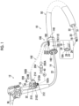
- Fig. 1 is an external view of a medical instrument guide device (hereinafter, referred to as a "guide tube") 10 according to a first embodiment of the present invention.
- Fig. 1 also shows an endoscope 12 in addition to the guide tube 10, and shows a usage form in which an insertion part 14 of the endoscope 12 is inserted into the guide tube 10.
- the endoscope 12 includes, as shown in Fig. 1 , the insertion part 14 and a hand operating part 16, and a proximal end side of the insertion part 14 is coupled to the hand operating part 16.
- the endoscope 12 is an example of a medical instrument according to the embodiment of the present invention, which is guided into the body by the guide tube 10.
- the insertion part 14 is configured by sequentially connecting a distal end hard part 18, a bendable part 20, and a soft part 22 from a distal end side toward the proximal end side.
- Fig. 1 shows a state in which the distal end sides of the distal end hard part 18, the bendable part 20, and the soft part 22 protrude to the outside from a distal end opening part 51 of a tube main body 50 forming the guide tube 10.
- the distal end hard part 18 includes, on a distal end surface 18A of the distal end hard part 18, a pair of illumination windows 24 for illuminating an inside of the body, an observation window 26 for acquiring a video of the inside of the body under the illumination from the illumination windows 24, and a treatment tool outlet port 28 for leading out a treatment tool, such as forceps or a high frequency treatment tool.
- a treatment tool insertion part 32 is provided to protrude on the hand operating part 16, and the treatment tool described above is inserted toward the treatment tool outlet port 28 from an insertion port 30 provided in the treatment tool insertion part 32. It should be noted that Fig. 1 shows a state in which the insertion port 30 is sealed by a cap 34.
- the bendable part 20 is operated to be bent in a desired direction by operating a pair of angle knobs 36 provided in the hand operating part 16.
- the soft part 22 is formed of a flexible member having the flexibility in a bending direction. Since the configuration of the endoscope 12 is well known in the related art, detailed illustration and the description thereof will be omitted here. Hereinafter, the guide tube 10 according to the first embodiment will be specifically described.
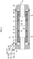
- Fig. 2 is an enlarged cross-sectional view of a main part particularly showing a configuration of the tube main body 50 of the guide tube 10 according to the first embodiment.
- the guide tube 10 comprises a long tube main body 50 to be inserted into the body and a handle part 100 (see Fig. 1 ) gripped by an operator.
- the respective axes of the tube main body 50 and the handle part 100 are arranged along a direction of an axis Ax of the guide tube 10.
- the configuration of the tube main body 50 will be described with reference to Fig. 2 .
- Fig. 2 is a schematic view showing the configuration of each member in an easy-to-understand manner, the scale of each member may be different from the actual scale.
- the tube main body 50 includes a flexible outer tube 52, a flexible inner tube 54 arranged inside the outer tube 52, and a shape deformable body 58 arranged in an inner space 56 between the outer tube 52 and the inner tube 54.
- an insertion passage 60 of the insertion part 14 (see Fig. 1 ) is defined by an inner peripheral surface of the inner tube 54.
- a hydrophilic coating 62 is formed on the inner peripheral surface of the inner tube 54, and thus a frictional resistance between the inner tube 54 and the insertion part 14 (see Fig. 1 ) is reduced.
- Each of the outer tube 52 and the inner tube 54 is made of, for example, a soft resin material which can be bent along the bending part of the intestinal tract.
- the soft resin material include urethane or polyester resin, but the present invention is not limited to this.
- a thickness of each of the outer tube 52 and the inner tube 54 is, for example, about 100 ⁇ m, and a thickness of the inner space 56 positioned between the outer tube 52 and the inner tube 54 is, for example, about 800 ⁇ m.
- the inner space 56 is a space of which a cross-sectional shape in a direction orthogonal to the axis Ax is formed in an annular shape to surround an outer periphery of the inner tube 54.
- the inner space 56 is sealed by a tubular cap 66 connected to a distal end part 50A of the tube main body 50 by an adhesive 64 and an inner sheath 110 (described later) connected to a proximal end part 50B of the tube main body 50 by an adhesive 68.
- the distal end opening part 51 shown in Fig. 1 is provided in the cap 66 of Fig. 2 .
- the shape deformable body 58 is deformable along the shapes of the outer tube 52 and the inner tube 54, and includes, as an example, a spiral tube 70 arranged along the direction of the axis Ax.
- Fig. 3 is a schematic view showing a configuration of a main part of the spiral tube 70.
- the spiral tube 70 is configured by spirally winding a band-shaped member 72 and is provided on an outer peripheral side of the inner tube 54 (see Fig. 2 ).
- the band-shaped member 72 is made of steel use stainless (SUS) as an example, but the present invention is not limited to this.
- SUS steel use stainless
- a thickness of the band-shaped member 72 is 300 ⁇ m or less.
- a high friction surface 74 is provided on an outer peripheral surface of the spiral tube 70.
- the high friction surface 74 include a resin layer obtained by coating an outer peripheral surface of the spiral tube 70 with a resin such as urethane coating or silica coating, a rough surface formed on the outer peripheral surface of the spiral tube 70, and a resin layer obtained by coating the rough surface thereof with a resin.
- a resin layer obtained by coating an outer peripheral surface of the spiral tube 70 with a resin such as urethane coating or silica coating a resin such as urethane coating or silica coating
- a rough surface formed on the outer peripheral surface of the spiral tube 70 a resin layer obtained by coating the rough surface thereof with a resin.
- the spiral tube 70 is firmly adhered to the inner tube 54. It should be noted that, since the spiral tube 70 has the flexibility in the bending direction, the shape thereof is deformable into, for example, the bent shape as shown in Fig. 4 .
- the shape deformable body 58 includes a sheet material 80 that can come into contact with the high friction surface 74 of the spiral tube 70.
- the sheet material 80 is formed in a cylindrical shape and is arranged along the direction of the axis Ax. As a result, the high friction surface 74 of the spiral tube 70 is covered with the sheet material 80.
- the sheet material 80 has the flexibility to be deformable along the shape of the tube main body 50 and is made of, for example, a resin such as urethane, but the present invention is not limited to this. In a case where the thickness of the tube main body 50 is, for example, about 1 mm, it is preferable that a thickness of the sheet material 80 is preferably 300 ⁇ m or less.
- the sheet material 80 includes a high friction surface 82 on an inner peripheral surface that is in contact with the high friction surface 74 of the spiral tube 70. Accordingly, in a case where the air in the inner space 56 is exhausted (sucked) by a vacuum pump 40 (see Figs. 1 and 2 ) and the inner space 56 is in a decompressed state (for example, a vacuum state), in the tube main body 50, the spiral tube 70 and the sheet material 80 are closely attached to and frictionally engaged with each other via the respective high friction surfaces 74 and 82. As a result, since the shape of the spiral tube 70 is held not to be deformable, the hardness of the tube main body 50 is changed from a soft state to a hard state, and the shape holding force of the tube main body 50 is enhanced.
- the tube main body 50 according to the present example is an example of a tube main body according to the embodiment of the present invention.
- the outer tube 52, the inner tube 54, and the shape deformable body 58 arranged along the longitudinal direction (axis Ax) of the tube main body 50 are portions of which the hardness is changed as described above, and are examples of a hardness change part according to the embodiment of the present invention.
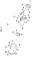
- Fig. 5 is an assembly perspective view in which each member of the handle part 100 is viewed from an oblique direction of a proximal end side (the left side in Fig. 5 ) of the axis Ax
- Fig. 6 is an assembly perspective view in which each member of the handle part 100 is viewed in an oblique direction on a distal end side (the right side of Fig. 6 ) of the axis Ax
- Fig. 7 is a cross-sectional view of the handle part 100 taken along the axis Ax.
- the handle part 100 is provided on the proximal end side of the tube main body 50, and includes the inner sheath 110 to which the proximal end part 50B of the tube main body 50 is connected, and a protection sheath 120 externally inserted into the inner sheath 110.
- the inner sheath 110 includes a port part 112 for supplying and discharging a fluid to and from the tube main body 50.
- the handle part 100 is an example of a handle part according to the embodiment of the present invention. It should be noted that each axis of the inner sheath 110 and the protection sheath 120 is arranged along the axis Ax.
- the inner sheath 110 has an outer diameter that is substantially equal to an outer diameter of the tube main body 50.
- an insertion passage 114 of the insertion part 14 is defined by an inner peripheral surface of the inner sheath 110. Therefore, the insertion part 14 (see Fig. 1 ) is inserted into the insertion passages 114 and 60 (see Fig. 2 ) defined by the inner peripheral surface of the inner sheath 110 and the inner peripheral surface of the inner tube 54 (see Fig. 2 ), respectively, and guided into the body.
- a hydrophilic coating 116 is also formed on the inner peripheral surface of the inner sheath 110 as in the inner tube 54, and thus a frictional resistance between the inner sheath 110 and the insertion part 14 is reduced.
- the inner sheath 110 is an example of an inner sheath according to the embodiment of the present invention.
- the protection sheath 120 has an inner diameter that is larger than the outer diameter of the inner sheath 110. As a result, the protection sheath 120 is formed to be externally insertable into the inner sheath 110.
- the protection sheath 120 is a member that is gripped by operator's fingers, and the outer diameter and the length of the protection sheath 120 in the direction of the axis Ax are formed in the size and the length enough to be gripped by the operator's fingers.
- the outer diameter of the protection sheath 120 is 3 to 4 cm
- the length of the protection sheath 120 in the direction of the axis Ax is about 8 to 10 cm.
- the protection sheath 120 is an example of a protection sheath according to the embodiment of the present invention. It should be noted that other configurations of the protection sheath 120 will be described later.
- connection portion 118 of the inner sheath 110 and the tube main body 50 a ring member 140 that surrounds an outer periphery of the connection portion 118 in a loosely fitted state is arranged.
- the connection portion 118 is a portion on which stress is concentrated and applied in a case where the tube main body 50 is operated to be bent, and includes, for example, a length portion of about 2 cm from the proximal end part 50B of the tube main body 50 toward the distal end side in the direction of the axis Ax (hereinafter, also referred to as a "proximal end side portion of the tube main body 50"), in addition to the proximal end part 50B of the tube main body 50 and a coating region with the adhesive 68 (see Fig.
- the ring member 140 has a function of relaxing the stress that is generated in the connection portion 118 in a case where the tube main body 50 is operated to be bent.
- the ring member 140 is an example of a stress relaxation ring according to the embodiment of the present invention.
- the guide tube 10 adopts a configuration in which the inner sheath 110 and the protection sheath 120 are coupled and fixed to the ring member 140.
- an example of the configuration for coupling and fixing the inner sheath 110 and the protection sheath 120 to the ring member 140 will be described.
- the ring member 140 includes a pair of arc-shaped protrusions 142 on a proximal end surface 140A of the ring member 140, and these protrusions 142 are provided to protrude from the proximal end surface 140A toward the proximal end side in the direction of the axis Ax. Further, these protrusions 142 are provided along a circumference centered on an axis (the axis Ax after the coupling and fixing) of the ring member 140, and the protection sheath 120 is coupled and fixed to the ring member 140 by externally fitting a proximal end side opening part 122 of the protection sheath 120 onto these protrusions 142.
- the ring member 140 includes three pins 144, 146, and 148 on the proximal end surface 140A, and these pins 144, 146, and 148 are provided to protrude from the proximal end surface 140A toward the proximal end side in the direction of the axis Ax.
- the pins 144, 146, and 148 are provided to be adjacent to each other, and the pin 148 is provided at a position spaced from the pins 144 and 146 by substantially 180 degrees in a circumferential direction.
- the three pins 144, 146, and 148 are fitted into three holes 150, 152, and 154 provided on the proximal end side of the inner sheath 110 shown in Fig. 6 .
- the pin 144 is fitted into the hole 150
- the pin 146 is fitted into the hole 152
- the pin 148 is fitted into the hole 154.
- the three pins 144, 146, and 148 are fitted into the three holes 150, 152, and 154 in this way, so that the inner sheath 110 is coupled and fixed to the ring member 140.
- the inner sheath 110 and the protection sheath 120 are coupled and fixed to the ring member 140.
- the configuration described above is an example of a configuration for coupling and fixing the inner sheath 110 and the protection sheath 120 to the ring member 140. It should be noted that it is preferable that the protection sheath 120 and the ring member 140 are fixed to each other by an adhesive (not shown) after the coupling and fixing described above.
- a leakage prevention valve 160 (see Figs. 5 and 6 ) is arranged inside the handle part 100.
- the leakage prevention valve 160 has a function of preventing a liquid from leaking from the tube main body 50 by coming into close contact with the outer peripheral surface of the insertion part 14 in a case where the insertion part 14 (see Fig. 1 ) is inserted into the handle part 100.
- an example of the configuration for arranging the leakage prevention valve 160 inside the handle part 100 will be described.
- the protection sheath 120 includes a flange-shaped valve pressing part 124 provided on the inner peripheral surface of the protection sheath 120.
- the leakage prevention valve 160 is interposed between the valve pressing part 124 and a proximal end part 110B of the inner sheath 110, and the position of the handle part 100 in the direction of the axis Ax is restricted.
- the leakage prevention valve 160 is formed in a substantially ring shape, and includes an annular valve body part 162, a tubular part 164 provided to protrude from an outer peripheral part of the valve body part 162 toward the distal end side in the direction of the axis Ax.
- An outer diameter of the tubular part 164 is smaller than the inner diameter of the protection sheath 120, and an inner diameter of the tubular part 164 is larger than the outer diameter of the inner sheath 110.
- an inner diameter of the valve body part 162 is smaller than the inner diameter of the inner sheath 110 and is smaller than the outer diameter of the insertion part 14 (see Fig. 1 ).
- the valve pressing part 124 is provided on an inner peripheral surface of a proximal end part 120B of the protection sheath 120, and an inner diameter of the valve pressing part 124 is larger than the inner diameter of the valve body part 162 and is smaller than the inner diameter of the inner sheath 110.
- the leakage prevention valve 160 is arranged with the valve body part 162 interposed between the valve pressing part 124 and the proximal end part 110B of the inner sheath 110.
- the leakage prevention valve 160 is an example of a leakage prevention valve according to the embodiment of the present invention
- the valve pressing part 124 is an example of a valve pressing part according to the embodiment of the present invention.
- the arrangement configuration described above is a configuration in which the valve pressing part 124 is provided on the proximal end part 120B of the protection sheath 120, but the present invention is not limited to this, and the valve pressing part 124 may be provided at a position spaced from the proximal end part 120B to the distal end side in the direction of the axis Ax.
- the above-described arrangement configuration in which the valve pressing part 124 is provided on the proximal end part 120B of the protection sheath 120 is preferable.
- the inner sheath 110 includes a base part 170 provided to protrude on an outer peripheral surface of the inner sheath 110.
- the protection sheath 120 includes a slit 180 open toward the tube main body 50 side.
- the protection sheath 120 is externally inserted into the inner sheath 110 in a state in which rotation of the protection sheath 120 is locked with respect to the inner sheath 110 by engaging the slit 180 and the base part 170 with each other.
- an example of the configuration for engaging the base part 170 and the slit 180 with each other will be described.
- the base part 170 is formed as a substantially rectangular plate-shaped part that extends from the distal end part 110A side of the inner sheath 110 toward the proximal end side in the direction of the axis Ax.
- the slit 180 is formed as a substantially rectangular notch part that is formed from the distal end part 120A of the protection sheath 120 toward the proximal end side in the direction of the axis Ax, and has a length in the direction of the axis Ax and a width in the circumferential direction about the axis Ax which are substantially the same length and width as the base part 170. Due to this configuration, the slit 180 and the base part 170 are engaged with each other.
- the protection sheath 120 is externally inserted into the inner sheath 110 in a state in which the rotation of the protection sheath 120 is locked in the circumferential direction about the axis Ax with respect to the inner sheath 110.
- the base part 170 is arranged to be exposed on an outer surface of the protection sheath 120 (see Fig. 1 ).
- the base part 170 is an example of an engaging part according to the embodiment of the present invention
- the slit 180 is an example of an engaged part according to the embodiment of the present invention. It should be noted that, as shown in Fig. 6 , the holes 150 and 152 into which the pins 144 and 146 (see Fig.
- the hole 154 into which the pin 148 (see Fig. 5 ) is fitted is provided in a distal end side surface of a protrusion part 172 provided to protrude from the outer peripheral surface of the inner sheath 110.
- the protrusion part 172 is engaged with a notch part 182 formed on the distal end part 120A of the protection sheath 120 during the external insertion.
- the port part 112 is provided in the base part 170.
- the port part 112 includes a port 190 for supplying and discharging the fluid (for example, air) to and from the tube main body 50 and a port 200 for supplying the liquid (for example, water) to the inner peripheral surface of the insertion passage 114 (inner peripheral surface of the inner sheath 110).
- the port part 112, the port 190, and the port 200 are examples of a port part, a fluid port, and a liquid port according to the embodiment of the present invention, respectively.
- the port 190 communicates with the inner space 56 (see Fig. 2 ) of the tube main body 50 via a flow passage 191 formed in the inner sheath 110
- the port 200 communicates with the inner peripheral surface of the inner sheath 110 via a flow passage 201 formed in the inner sheath 110.
- the port 190 and the port 200 are installed adjacent to each other along the direction of the axis Ax of the inner sheath 110.
- the port 190 and the port 200 are installed adjacent to each other along the same axis parallel to the axis Ax.
- the port 200 is arranged on a side opposite to a side of the inner sheath 110 to which the tube main body 50 is connected, with respect to the port 190.
- the port 200 is arranged on the proximal end side in the direction of the axis Ax with respect to the port 190.
- a tube 192 is connected to the port 190, and a tube 202 is connected to the port 200.
- a pull-out direction B of a proximal end side portion 193 of the tube 192 from the port 190 and a pull-out direction C of a proximal end side portion 203 of the tube 202 from the port 200 are set to be the same direction.
- both the pull-out directions B and C are set to be directions perpendicular to the direction of the axis Ax of the inner sheath 110.
- the proximal end side portion 193 of the tube 192 includes an insertion portion that is inserted (fitted) into the port 190 that is a hole
- the proximal end side portion 203 of the tube 202 includes an insertion portion that is inserted (fitted) into the port 200 that is a hole.
- the tube 192 is an example of a fluid tube according to the embodiment of the present invention
- the tube 202 is an example of a liquid tube according to the embodiment of the present invention.
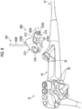
- Fig. 8 is a perspective view of a switching unit 208 provided in the middle of the tube 192.
- the switching unit 208 is an example of a switching unit according to the embodiment of the present invention. Further, the switching unit 208 according to the present example includes a three way stopcock 210.
- a function of the three way stopcock 210 will be described with reference to a schematic view of the three way stopcock 210 shown in Fig. 2 .
- the three way stopcock 210 includes a first port 210A connected to the tube 192A on the vacuum pump 40 side, a second port 210B connected to the tube 192B on the port 190 side, and a third port 210C for opening to the atmosphere, in the tube 192. Also, the three way stopcock 210 includes a cock 212. By operating the cock 212 to be moved rotationally, the operator can selectively switch between an ON mode in which the first port 210A and the second port 210B communicate with each other and an OFF mode in which the second port 210B and the third port 210C communicate with each other.
- the vacuum pump 40 and the inner space 56 of the tube main body 50 communicate with each other via the tube 192 and the flow passage 191.
- the air in the inner space 56 is exhausted (sucked) by the vacuum pump 40, the inner space 56 is in the decompressed state (for example, the vacuum state), and the hardness of the tube main body 50 is in the hard state.
- the cock 212 is switched to the OFF mode, the inner space 56 and outside air communicate with each other via the tube 192 and the flow passage 191.
- the three way stopcock 210 is an example of a switching member according to the embodiment of the present invention.
- the switching unit 208 includes a hook 214 attachably and detachably fixable to the endoscope 12.
- the hook 214 includes an opening part 216 that can be fitted into the treatment tool insertion part 32 of the endoscope 12.
- the opening part 216 of the hook 214 is fitted into the treatment tool insertion part 32, so that the hook 214 is fixed to the treatment tool insertion part 32 and the switching unit 208 is arranged on the hand operating part 16 (see Fig. 1 ).
- the operator who operates the hand operating part 16 can operate the cock 212 of the three way stopcock 210.
- the hook 214 is an example of a fixing part according to the embodiment of the present invention
- the opening part 216 is an example of a fitting part according to the embodiment of the present invention.
- the cock 212 of the three way stopcock 210 is arranged on a side opposite to the port 190 side with respect to the hook 214.
- the cock 212 of the three way stopcock 210 is arranged on the vacuum pump 40 side with respect to the hook 214.
- the tube 192 (including the tube 192A and the tube 192B) has a length (for example, about 3 to 5 meters) required for connecting the port 190 and the vacuum pump 40, the tube 192B need only have a length (for example, about 1 meter) for arranging the switching unit 208 on the hand operating part 16.
- the switching unit 208 is provided in the tube 192 at an intermediate position spaced from the port 190 by about 1 meter. The switching unit 208 is provided at such an intermediate position, so that the operator can operate the cock 212 of the three way stopcock 210 without drawing the tube 192B.
- a syringe 204 is connected to a distal end part 202A of the tube 202.
- the liquid for example, water
- the liquid can be supplied from the tube 202 to the inner peripheral surface of the inner sheath 110 via the flow passage 201 of Fig. 7 by the operator operating the syringe.
- the hydrophilic coating 116 formed on the inner peripheral surface of the inner sheath 110 can be wetted with the liquid.
- the tube 202 need only have, for example, a length (for example, about 1 meter) that is substantially equal to the length of the tube 192B. As a result, the operator can operate the syringe 204 without drawing the tube 202.
- the protection sheath 120 includes a first sleeve part 126 and a second sleeve part 128.
- the first sleeve part 126 and the second sleeve part 128 are arranged along the direction of the axis Ax, the first sleeve part 126 is arranged on the tube main body 50 side, and the second sleeve part 128 is arranged on a side opposite to the tube main body 50 side with respect to the first sleeve part 126.
- the second sleeve part 128 is arranged on the proximal end side in the direction of the axis Ax with respect to the first sleeve part 126. Further, the second sleeve part 128 is formed to have a larger outer diameter than the first sleeve part 126.
- the first sleeve part 126 is a portion that forms a body part of the protection sheath 120, that is, the first sleeve part 126 functions as a portion that is formed to be longer than the second sleeve part 128 in the direction of the axis Ax and is gripped by the operator's fingers.
- the first sleeve part 126 is an example of a first sleeve part according to the embodiment of the present invention.
- the second sleeve part 128 is formed in a flange shape on the proximal end part 120B of the protection sheath 120.
- the second sleeve part 128 is provided mainly to form a step part 130 between the second sleeve part 128 and the first sleeve part 126, and the operator can use this step part 130 as a finger hook part for hooking the fingers.
- the second sleeve part 128 is an example of a second sleeve part according to the embodiment of the present invention.
- the insertion part 14 and the tube main body 50 each have the flexibility, in a case where the insertion part 14 (see Fig. 1 ) inserted into the insertion passages 114 and 60 (see Fig. 7 ) of the guide tube 10 is inserted along the large intestine 400 (see Fig. 10 ) together with the tube main body 50, the insertion part 14 and the tube main body 50 are smoothly inserted along a bent shape of the large intestine 400.
- the cock 212 of the three way stopcock 210 is operated to switch to the ON mode. Then, the air in the inner space 56 is exhausted (sucked) by the vacuum pump 40 (see Fig. 1 ), the sheet material 80 is pressed against the outer tube 52, and the spiral tube 70 is pressed against the inner tube 54. As a result, the high friction surface 74 of the spiral tube 70 and the high friction surface 82 of the sheet material 80 are closely attached to and frictionally engaged with each other. As a result, the tube main body 50 is hardened in a shape corresponding to the bent shape of the sigmoid colon 402, and the shape is held, so that the insertability of the insertion part 14 into the sigmoid colon 402 is improved.
- the treatment of a lesion portion 406 of a transverse colon 404 is started by causing the bendable part 20 of the insertion part 14 to protrude forward from the distal end opening part 51 of the guide tube 10 and then leading out the treatment tool (not shown) forward from the treatment tool outlet port 28 (see Fig. 1 ) of the distal end hard part 18.
- the distal end hard part 18 can be positioned at an accurate treatment position, and as a result, it is possible to perform an accurate treatment on the lesion portion 406.
- the operator inserts the tube main body 50 of the guide tube 10 and the insertion part 14 into the body while generally gripping the hand operating part 16 with the left hand and gripping the handle part 100 of the guide tube 10 and the insertion part 14 with the right hand. Then, in a case where the hardness of the tube main body 50 is changed, the cock 212 of the three way stopcock 210 is operated with the right hand. Then, in a case where the treatment for the lesion portion 406 is finished, the handle part 100 and the insertion part 14 are similarly gripped with the right hand to pull out the tube main body 50 and the insertion part 14 from the inside of the body.
- the tube main body 50 (including the insertion part 14) in the soft state is hardened in a state along the bent shape of the sigmoid colon 402, but the present invention is not limited to this operation method.
- an operation method may be adopted in which the sigmoid colon 402 is linearized with the tube main body 50 (including the insertion part 14) in the soft state and then the tube main body 50 is hardened.
- the tube main body 50 (including the insertion part 14) in the soft state is inserted along the bent shape of the sigmoid colon 402, and in a case where the distal end of the tube main body 50 reaches a spleen portion (not shown), the tube main body 50 is operated in the pulling-out direction while being rotated about the axis Ax.
- the sigmoid colon 402 can be linearized.
- an operation method may be adopted in which the tube main body 50 is inserted into the intestinal tract after the intestinal tract is linearized to a certain extent by the insertion part 14, and then the tube main body 50 is hardened.
- the handle part 100 since the simple configuration is adopted in which the handle part 100 includes the inner sheath 110 to which the proximal end part 50B of the tube main body 50 is connected and that includes the port part 112 for supplying and discharging the fluid to and from the tube main body 50, and the protection sheath 120 externally inserted into the inner sheath 110, the handle part 100 is easily gripped by the operator who operates the guide tube 10. As a result, with the guide tube 10 according to the first embodiment, it is possible to improve the operability of the endoscope 12 that is operated by using the guide tube 10.
- the guide tube 10 adopts the configuration in which the ring member 140 that surrounds the outer periphery of the connection portion 118 between the inner sheath 110 and the tube main body 50 in the loosely fitted state is arranged, the stress generated in the connection portion 118 in a case where the tube main body 50 is bent can be relaxed by the ring member 140.
- the guide tube 10 adopts the configuration in which the leakage prevention valve 160 is arranged inside the handle part 100, for example, the leakage prevention valve 160 can be arranged in the handle part 100 with a simpler configuration than a configuration in which the leakage prevention valve 160 is externally attached to the outside of the handle part 100 by using a cap. As a result, the ease of assembly of the handle part 100 is improved.
- the guide tube 10 since the configuration is adopted in which the position of the leakage prevention valve 160 in the direction of the axis Ax is restricted by interposing the leakage prevention valve 160 between the flange-shaped valve pressing part 124 provided on the inner peripheral surface of the protection sheath 120 and the proximal end part 110B of the inner sheath 110, it is possible to restrict the misregistration of the leakage prevention valve 160 in the direction of the axis Ax with a simple configuration. In addition, with the configuration of the present example, it is also possible to restrict the misregistration of the leakage prevention valve 160 in the direction perpendicular to the axis Ax. Therefore, with the configuration of the present example, it is possible to effectively prevent the liquid from leaking.
- the guide tube 10 adopts the configuration in which the protection sheath 120 is externally inserted into the inner sheath 110 in a state in which the rotation of the protection sheath 120 is locked with respect to the inner sheath 110 by engaging the base part 170 with the slit 180, it is possible to realize the lock of the rotation of the protection sheath 120 with a simple configuration. As a result, the ease of assembly of the handle part 100 is improved.
- the guide tube 10 adopts the configuration in which the port part 112 is provided at the base part 170, that is, the configuration in which the port part 112 is provided at the base part 170 exposed to the outside of the handle part 100, the connection work of connecting the tube 192 for supplying and discharging the fluid to the port part 112 is facilitated.
- the port part 112 includes the port 190 and the port 200, the connection work of connecting the tube 192 to the port 190 and the connection work of connecting the tube 202 to the port 200 are facilitated.
- the operator can grip the handle part 100 without being obstructed by the tube 192 and the tube 202.
- the operability of the guide tube 10 and the endoscope 12 is improved.
- the tube 192 and the tube 202 may obstruct the operator who grips the handle part 100.
- such a problem can be eliminated.
- the guide tube 10 since the configuration is adopted in which the port 200 is arranged on the side opposite to the side of the inner sheath 110 to which the tube main body 50 is connected, with respect to the port 190, the flow passage 191 from the port 190 toward the tube main body 50 and the flow passage 201 from the port 200 toward the insertion passage 114 can be arranged without intersecting each other. In other words, as shown in Fig.
- both flow passages 191 and 201 can be arranged without intersecting each other. Therefore, by adopting the configuration of the present example, the two flow passages 191 and 201 can be arranged on the inner sheath 110 with a simple configuration.
- the guide tube 10 since the configuration is adopted in which the pull-out direction B of the proximal end side portion 193 of the tube 192 from the port 190 and the pull-out direction C of the proximal end side portion 203 of the tube 202 from the port 200 are set to be the same direction, the operator can grip the handle part 100 without being obstructed by the tube 192 and the tube 202. As a result, the operability of the guide tube 10 and the endoscope 12 is improved.
- the tube 192 and the tube 202 may obstruct the operator who grips the handle part 100.
- the configuration of the present example such a problem can be eliminated.
- the guide tube 10 since the configuration is adopted in which the pull-out directions B and C are the directions perpendicular to the direction of the axis Ax of the inner sheath 110, it is possible for the operator who views the handle part 100 to easily visually recognize, in terms of appearance, a boundary between a handle area (outer surface of the protection sheath 120) gripped by the operator and a tube area (outer surface of the base part 170) to which the tube 192 and the tube 202 are connected. As a result, the operator can avoid the tube area and grip the handle area only by viewing the handle part 100 at a glance. As a result, the operability of the guide tube 10 and the endoscope 12 is improved.
- the protection sheath 120 since the configuration is adopted in which the protection sheath 120 includes the first sleeve part 126 arranged on the tube main body 50 side and the second sleeve part 128 arranged on the side opposite to the tube main body 50 side with respect to the first sleeve part 126 and having a larger outer diameter than the first sleeve part 126, as shown in Fig. 11 , it is possible to use the step part 130 formed between the first sleeve part 126 and the second sleeve part 128 as the finger hook part for hooking the operator's fingers.
- Fig. 11 shows an operation example of the endoscope 12 using the guide tube 10, but the tubes 192 and 202 (see Fig. 7 ) are not shown.
- the guide tube 10 adopts the configuration in which the switching unit 208 is provided in the middle of the tube 192, the operator can operate the cock 212 of the three way stopcock 210 without drawing the tube 192B. As a result, the operability of the guide tube 10 and the endoscope 12 is improved.
- the switching unit 208 since the configuration is adopted in which the switching unit 208 includes the hook 214 attachably and detachably fixable to the endoscope 12, the switching unit 208 can be fixed to the endoscope 12 by using the hook 214. As a result, since the operator can operate the cock 212 of the three way stopcock 210 while operating the endoscope 12, the operability of the guide tube 10 and the endoscope 12 is improved.
- the switching unit 208 can be fixed to the endoscope 12 by only fitting the opening part 216 of the hook 214 into the treatment tool insertion part 32.
- the operator can, for example, operate the cock 212 of the three way stopcock 210 with the left hand while gripping the hand operating part 16 with the left hand and operating the endoscope 12 (for example, operating the bendable part 20 to be bent).
- the operability of the guide tube 10 and the endoscope 12 is improved.
- Fig. 12 is an external view showing a main part of a guide tube 300 according to a second embodiment.
- the same members as or members similar to the members of the guide tube 10 according to the first embodiment shown in Figs. 1 to 11 will be denoted by the same reference numerals.
- first sleeve part 126 of the protection sheath 120 (see Figs. 5 to 7 ) according to the first embodiment has the same outer diameter over the entire direction of the axis Ax
- a first sleeve part 304 of a protection sheath 302 according to the second embodiment includes a sleeve body large-diameter part 306 and a sleeve body small-diameter part 308 which have different outer diameters in the direction of the axis Ax. Since other configurations are the same, a protection sheath 302 according to the second embodiment will be described here.
- Fig. 13 is a perspective view of the protection sheath 302 as viewed from an oblique direction on a proximal end side (the left side in Fig. 13 ) of the axis Ax
- Fig. 14 is a perspective view of the protection sheath 302 as viewed from an oblique direction on a distal end side (the right side in Fig. 14 ) of the axis Ax.
- the first sleeve part 304 includes the sleeve body large-diameter part 306 arranged on the tube main body 50 side, and the sleeve body small-diameter part 308 arranged on a side opposite to the tube main body 50 side with respect to the sleeve body large-diameter part 306.
- the sleeve body small-diameter part 308 is arranged on the proximal end side in the direction of the axis Ax with respect to the sleeve body large-diameter part 306.
- the sleeve body small-diameter part 308 is formed to have a smaller outer diameter than the sleeve body large-diameter part 306 and the second sleeve part 128, and is arranged on the distal end side in the direction of the axis Ax with respect to the second sleeve part 128. Further, the sleeve body small-diameter part 308 is formed such that a length in the direction of the axis Ax of the sleeve body small-diameter part 308 is longer than a length in the direction of the axis Ax of the second sleeve part 128.
- the sleeve body small-diameter part 308 is arranged on a side opposite to the tube main body 50 side with respect to the port part 112. In other words, the sleeve body small-diameter part 308 is arranged on the proximal end side in the direction of the axis Ax with respect to the port part 112.
- the first sleeve part 304 since the first sleeve part 304 includes the sleeve body large-diameter part 306 arranged on the tube main body 50 side, and the sleeve body small-diameter part 308 arranged on a side opposite to the tube main body 50 side with respect to the sleeve body large-diameter part 306, as shown in Fig. 15 , the sleeve body small-diameter part 308 formed between the sleeve body large-diameter part 306 and the second sleeve part 128 can be used as a finger insertion part into which the operator's fingers are inserted.
- the operator can perform the operation of inserting, for example, the index finger and the middle finger into the sleeve body small-diameter part 308 of the guide tube 300, inserting and pulling out the insertion part 14 into and from the guide tube 300 in a state where the sleeve body small-diameter part 308 is pinched with the index finger and the middle finger, and or pulling out the guide tube 300 itself from the inside of the body.
- the guide tube 300 according to the second embodiment, the operability of the endoscope 12 can be improved.
- Fig. 15 shows an operation example of the endoscope 12 using the guide tube 300, but the tubes 192 and 202 (see Fig. 7 ) are not shown.
- Fig. 15 shows an example in which the sleeve body small-diameter part 308 is pinched by the index finger and the middle finger, but the present invention is not limited to this.
- the operation of inserting and pulling out the guide tube 300 may be performed in a state in which the operator's index finger is hooked along an outer peripheral surface of the sleeve body small-diameter part 308.
- the protection sheath 302 is formed such that the length in the direction of the axis Ax of the sleeve body small-diameter part 308 is longer than the length in the direction of the axis Ax of the second sleeve part 128, the sleeve body small-diameter part 308 can be effectively used as a portion pinched or gripped by the operator. As a result, a force for the operation of inserting and pulling out the guide tube 300 can be effectively transmitted to the guide tube 300.
- the second sleeve part 128 need only be formed as a sleeve part for forming the step part 130 for hooking the fingers, even in a case where the length in the direction of the axis Ax of the second sleeve part 128 is shorter than the length in the direction of the axis Ax of the sleeve body small-diameter part 308, the function of the guide tube 300 is not hindered.
- the sleeve body small-diameter part 308 is arranged on the side opposite to the tube main body 50 side with respect to the port part 112, the sleeve body small-diameter part 308 can be pinched or gripped with the operator's fingers without being obstructed by the port part 112.
- Fig. 16 shows a modification example of a switching unit 310 including the three way stopcock 210.
- the switching unit 310 is an example of a switching unit according to the embodiment of the present invention.
- the switching unit 310 includes a hook 312 bent in a C-shape by an elastic plate material.
- the hook 312 can be mounted on a cylindrical part 35 positioned between the treatment tool insertion part 32 and a bending prevention part 33 of the hand operating part 16 with one touch.
- the switching unit 310 can be fixed to the hand operating part 16 by using the hook 312.
- the hook 312 is an example of a fixing part according to the embodiment of the present invention. It should be noted that, even in the switching unit 310 according to the present example, since the three way stopcock 210 is arranged on a side opposite to the port 190 side with respect to the hook 312, the operability of the cock 212 of the three way stopcock 210 is improved.
- the tube main body 50 including the hardness change part is described as the tube main body applied to the medical instrument guide device according to the embodiment of the present invention, the present invention is not limited to this.
- an overtube for an endoscope comprising a balloon at the distal end part and having a flow passage for supplying and discharging the fluid to and from the balloon may be applied.
- the present invention is not limited to this.
- the present invention can be applied to a medical instrument, such as a manipulator.
- a medical instrument guide device having an insertion passage for guiding a medical instrument into a body
- the medical instrument guide device comprising: a long tube main body to be inserted into the body; and a handle part provided on a proximal end side of the tube main body, in which the handle part includes an inner sheath to which a proximal end part of the tube main body is connected and a protection sheath externally inserted into the inner sheath, and the inner sheath includes a port part for supplying and discharging a fluid to and from the tube main body.
- the medical instrument guide device in which the tube main body includes a hardness change part that is arranged along a longitudinal direction of the tube main body and of which hardness is changed due to the fluid supplied and discharged from the port part.
- the medical instrument guide device in which a stress relaxation ring that surrounds an outer periphery of a connection portion between the inner sheath and the tube main body in a loosely fitted state is arranged, and the inner sheath and the protection sheath are coupled and fixed to the stress relaxation ring.
- the medical instrument guide device according to any one of Inventions 1 to 3, in which a leakage prevention valve that prevents a liquid from leaking from the tube main body is arranged inside the handle part.
- the medical instrument guide device in which the protection sheath includes a flange-shaped valve pressing part provided on an inner peripheral surface of the protection sheath, and the leakage prevention valve is interposed between the valve pressing part and a proximal end part of the inner sheath so that a position of the handle part in an axial direction is restricted.
- the protection sheath includes a slit-shaped engaged part open toward a tube main body side, and the protection sheath is externally inserted into the inner sheath in a state in which rotation of the protection sheath is locked with respect to the inner sheath by engaging the engaged part and the engaging part with each other.
- the tube main body includes a hardness change part that is arranged along a longitudinal direction of the tube main body and of which hardness is changed due to the fluid supplied and discharged from the port part
- the port part includes a fluid port for supplying and discharging the fluid to and from the tube main body, and a liquid port for supplying a liquid to an inner peripheral surface of the insertion passage.
- the medical instrument guide device in which the liquid port is arranged on a side opposite to a side of the inner sheath to which the tube main body is connected, with respect to the fluid port.
- the medical instrument guide device according to any one of Inventions 8 to 10, further comprising: a fluid tube connected to the fluid port; and a liquid tube connected to the liquid port, in which a pull-out direction of a proximal end side portion of the fluid tube from the fluid port and a pull-out direction of a proximal end side portion of the liquid tube from the liquid port are the same direction as each other.
- the medical instrument guide device in which the pull-out direction of the proximal end side portion of the fluid tube from the fluid port and the pull-out direction of the proximal end side portion of the liquid tube from the liquid port are directions perpendicular to the axial direction of the inner sheath.
- the protection sheath includes a first sleeve part arranged on a tube main body side, and a second sleeve part arranged on a side opposite to the tube main body side with respect to the first sleeve part and having a larger outer diameter than the first sleeve part.
- the first sleeve part includes a sleeve body large-diameter part arranged on the tube main body side, and a sleeve body small-diameter part arranged on a side opposite to the tube main body side with respect to the sleeve body large-diameter part and having a smaller outer diameter than the sleeve body large-diameter part.
- the medical instrument guide device according to Invention 14 or 15, in which the sleeve body small-diameter part is arranged on a side opposite to the tube main body side with respect to the port part.
- the tube main body includes a hardness change part that is arranged along a longitudinal direction of the tube main body and of which hardness is changed due to the fluid supplied and discharged from the port part
- the port part includes a fluid port for supplying and discharging the fluid to and from the tube main body
- a fluid tube connected to the fluid port is provided
- a switching unit is provided in a middle of the fluid tube, and the switching unit includes a switching member capable of switching supply and discharge of the fluid for the fluid port.
- the medical instrument guide device in which the switching unit includes a fixing part attachably and detachably fixable to the medical instrument.
- the medical instrument guide device in which the medical instrument is an endoscope having an insertion part to be inserted into the body, and the fixing part includes a fitting part capable of being fitted into a treatment tool insertion part of the endoscope.
- the medical instrument guide device according to Invention 18 or 19, in which the switching member is arranged on a side opposite to a side of the fluid port with respect to the fixing part.
Landscapes
- Health & Medical Sciences (AREA)
- Life Sciences & Earth Sciences (AREA)
- Surgery (AREA)
- Nuclear Medicine, Radiotherapy & Molecular Imaging (AREA)
- Biomedical Technology (AREA)
- Optics & Photonics (AREA)
- Pathology (AREA)
- Radiology & Medical Imaging (AREA)
- Biophysics (AREA)
- Engineering & Computer Science (AREA)
- Physics & Mathematics (AREA)
- Heart & Thoracic Surgery (AREA)
- Medical Informatics (AREA)
- Molecular Biology (AREA)
- Animal Behavior & Ethology (AREA)
- General Health & Medical Sciences (AREA)
- Public Health (AREA)
- Veterinary Medicine (AREA)
- Endoscopes (AREA)
Abstract
Provided is a medical instrument guide device that can improve the operability of a medical instrument.
A guide tube of the embodiment includes a long tube main body (50) to be inserted into a body, and a handle part (100) provided on a proximal end side of the tube main body, in which the handle part includes an inner sheath (110) to which a proximal end part (110B) of the tube main body is connected and a protection sheath (120) externally inserted into the inner sheath, and the inner sheath includes a port part (112) for supplying and discharging a fluid to and from the tube main body.
Description
- The present invention relates to a medical instrument guide device for guiding a medical instrument, such as an endoscope insertion part, into a body.
- An insertion part of an endoscope (hereinafter, also referred to as an "endoscope insertion part") is inserted along a winding and flexible insertion path such as an upper digestive tract or a lower digestive tract. Therefore, the endoscope insertion part has the flexibility that can be inserted along the insertion path.
- However, since the intestinal tract, which is an example of the insertion path, has a portion that is not fixed to the body (for example, a sigmoid colon) and the above-described portion is deformed in the middle even though the insertion part is pushed during insertion of the endoscope insertion part, there is a problem that it is difficult for a distal end part of the insertion part to move forward. Further, there is a case where a treatment tool is led out from the distal end part of the insertion part to perform a precise operation of cutting out a lesion portion during treatment of the endoscope, but there is a case where the deformation of the above-described portion interferes with the precise operation.
- Therefore,
JP2021-531111A JP2021-531111A - However, since the handle (handle part) of the hardening device system (medical instrument guide device) in
JP2021-531111A - The present invention has been made in view of such circumstances, and is to provide a medical instrument guide device that can improve the operability of a medical instrument.
- In order to solve the above problems, an aspect of the present invention relates to a medical instrument guide device having an insertion passage for guiding a medical instrument into a body, the medical instrument guide device comprising: a long tube main body to be inserted into the body; and a handle part provided on a proximal end side of the tube main body, in which the handle part includes an inner sheath to which a proximal end part of the tube main body is connected and a protection sheath externally inserted into the inner sheath, and the inner sheath includes a port part for supplying and discharging a fluid to and from the tube main body.
- According to an embodiment, it is preferable that the tube main body includes a hardness change part that is arranged along a longitudinal direction of the tube main body and of which hardness is changed due to the fluid supplied and discharged from the port part.
- According to an embodiment, it is preferable that a stress relaxation ring that surrounds an outer periphery of a connection portion between the inner sheath and the tube main body in a loosely fitted state is arranged, and the inner sheath and the protection sheath are coupled and fixed to the stress relaxation ring.
- According to an embodiment, it is preferable that a leakage prevention valve that prevents a liquid from leaking from the tube main body is arranged inside the handle part.
- According to an embodiment, it is preferable that the protection sheath includes a flange-shaped valve pressing part provided on an inner peripheral surface of the protection sheath, and the leakage prevention valve is interposed between the valve pressing part and a proximal end part of the inner sheath so that a position of the handle part in an axial direction is restricted.
- According to an embodiment, it is preferable that an engaging part is provided to protrude on an outer peripheral surface of the inner sheath, the protection sheath includes a slit-shaped engaged part open toward a tube main body side, and the protection sheath is externally inserted into the inner sheath in a state in which rotation of the protection sheath is locked with respect to the inner sheath by engaging the engaged part and the engaging part with each other.
- According to an embodiment, it is preferable that the port part is provided in the engaging part.
- According to an embodiment, it is preferable that the tube main body includes a hardness change part that is arranged along a longitudinal direction of the tube main body and of which hardness is changed due to the fluid supplied and discharged from the port part, and the port part includes a fluid port for supplying and discharging the fluid to and from the tube main body, and a liquid port for supplying a liquid to an inner peripheral surface of the insertion passage.
- According to an embodiment, it is preferable that the fluid port and the liquid port are installed adjacent to each other along an axial direction of the inner sheath.
- According to an embodiment, it is preferable that the liquid port is arranged on a side opposite to a side of the inner sheath to which the tube main body is connected, with respect to the fluid port.
- According to an embodiment, it is preferable that the medical instrument guide device further comprise: a fluid tube connected to the fluid port; and a liquid tube connected to the liquid port, in which a pull-out direction of a proximal end side portion of the fluid tube from the fluid port and a pull-out direction of a proximal end side portion of the liquid tube from the liquid port are the same direction as each other.
- According to an embodiment, it is preferable that the pull-out direction of the proximal end side portion of the fluid tube from the fluid port and the pull-out direction of the proximal end side portion of the liquid tube from the liquid port are directions perpendicular to the axial direction of the inner sheath.
- According to an embodiment, it is preferable that the protection sheath includes a first sleeve part arranged on a tube main body side, and a second sleeve part arranged on a side opposite to the tube main body side with respect to the first sleeve part and having a larger outer diameter than the first sleeve part.
- According to an embodiment, it is preferable that the first sleeve part includes a sleeve body large-diameter part arranged on the tube main body side, and a sleeve body small-diameter part arranged on a side opposite to the tube main body side with respect to the sleeve body large-diameter part and having a smaller outer diameter than the sleeve body large-diameter part.
- According to an embodiment, it is preferable that an axial length of the sleeve body small-diameter part is longer than an axial length of the second sleeve part.
- According to an embodiment, it is preferable that the sleeve body small-diameter part is arranged on a side opposite to the tube main body side with respect to the port part.
- According to an embodiment, it is preferable that the tube main body includes a hardness change part that is arranged along a longitudinal direction of the tube main body and of which hardness is changed due to the fluid supplied and discharged from the port part, the port part includes a fluid port for supplying and discharging the fluid to and from the tube main body, a fluid tube connected to the fluid port is provided, a switching unit is provided in a middle of the fluid tube, and the switching unit includes a switching member capable of switching supply and discharge of the fluid for the fluid port.
- According to an embodiment, it is preferable that the switching unit includes a fixing part attachably and detachably fixable to the medical instrument.
- According to an embodiment, it is preferable that the medical instrument is an endoscope having an insertion part to be inserted into the body, and the fixing part includes a fitting part capable of being fitted into a treatment tool insertion part of the endoscope.
- According to an embodiment, it is preferable that the switching member is arranged on a side opposite to a side of the fluid port with respect to the fixing part.
- According to the present invention, the operability of the medical instrument can be improved.
-
-
Fig. 1 is an external view of a guide tube according to a first embodiment. -
Fig. 2 is an enlarged cross-sectional view of a main part showing a configuration of the guide tube. -
Fig. 3 is a schematic view showing a configuration of a main part of a spiral tube. -
Fig. 4 is an explanatory view showing a state in which the spiral tube is bent. -
Fig. 5 is an assembly perspective view of a handle part as viewed from an oblique direction on a proximal end side of an axis. -
Fig. 6 is an assembly perspective view of the handle part as viewed from an oblique direction on a distal end side of the axis. -
Fig. 7 is a cross-sectional view showing a configuration of the handle part. -
Fig. 8 is a perspective view of a three way stopcock provided in the middle of a fluid tube. -
Fig. 9 is a perspective view of a main part in which the three way stopcock is attachably and detachably fixed to an endoscope by a hook. -
Fig. 10 is an explanatory view showing a treatment example of the endoscope using the guide tube. -
Fig. 11 is an explanatory view of a main part showing an operation example of the endoscope using the guide tube according to the first embodiment. -
Fig. 12 is an external view showing a main part of a guide tube according to a second embodiment. -
Fig. 13 is a perspective view of a protection sheath ofFig. 12 as viewed in an oblique direction on a proximal end side of an axis. -
Fig. 14 is a perspective view of the protection sheath ofFig. 12 as viewed in an oblique direction on a distal end side of the axis. -
Fig. 15 is an explanatory view of a main part showing an operation example of an endoscope using the guide tube according to the second embodiment. -
Fig. 16 is a perspective view showing a modification example for arranging the three way stopcock in the endoscope. - Hereinafter, embodiments of a medical instrument guide device of the present invention will be described with reference to the accompanying drawings.
-
Fig. 1 is an external view of a medical instrument guide device (hereinafter, referred to as a "guide tube") 10 according to a first embodiment of the present invention.Fig. 1 also shows anendoscope 12 in addition to theguide tube 10, and shows a usage form in which aninsertion part 14 of theendoscope 12 is inserted into theguide tube 10. - First, the
endoscope 12 will be described. Theendoscope 12 includes, as shown inFig. 1 , theinsertion part 14 and ahand operating part 16, and a proximal end side of theinsertion part 14 is coupled to thehand operating part 16. Theendoscope 12 is an example of a medical instrument according to the embodiment of the present invention, which is guided into the body by theguide tube 10. - The
insertion part 14 is configured by sequentially connecting a distal endhard part 18, abendable part 20, and asoft part 22 from a distal end side toward the proximal end side.Fig. 1 shows a state in which the distal end sides of the distal endhard part 18, thebendable part 20, and thesoft part 22 protrude to the outside from a distalend opening part 51 of a tubemain body 50 forming theguide tube 10. - The distal end
hard part 18 includes, on adistal end surface 18A of the distal endhard part 18, a pair ofillumination windows 24 for illuminating an inside of the body, anobservation window 26 for acquiring a video of the inside of the body under the illumination from theillumination windows 24, and a treatmenttool outlet port 28 for leading out a treatment tool, such as forceps or a high frequency treatment tool. A treatmenttool insertion part 32 is provided to protrude on thehand operating part 16, and the treatment tool described above is inserted toward the treatmenttool outlet port 28 from aninsertion port 30 provided in the treatmenttool insertion part 32. It should be noted thatFig. 1 shows a state in which theinsertion port 30 is sealed by acap 34. - The
bendable part 20 is operated to be bent in a desired direction by operating a pair of angle knobs 36 provided in thehand operating part 16. Thesoft part 22 is formed of a flexible member having the flexibility in a bending direction. Since the configuration of theendoscope 12 is well known in the related art, detailed illustration and the description thereof will be omitted here. Hereinafter, theguide tube 10 according to the first embodiment will be specifically described. -
Fig. 2 is an enlarged cross-sectional view of a main part particularly showing a configuration of the tubemain body 50 of theguide tube 10 according to the first embodiment. As shown inFig. 2 , theguide tube 10 comprises a long tubemain body 50 to be inserted into the body and a handle part 100 (seeFig. 1 ) gripped by an operator. The respective axes of the tubemain body 50 and thehandle part 100 are arranged along a direction of an axis Ax of theguide tube 10. Hereinafter, the configuration of the tubemain body 50 will be described with reference toFig. 2 . It should be noted that, sinceFig. 2 is a schematic view showing the configuration of each member in an easy-to-understand manner, the scale of each member may be different from the actual scale. - As shown in
Fig. 2 , the tubemain body 50 includes a flexibleouter tube 52, a flexibleinner tube 54 arranged inside theouter tube 52, and a shapedeformable body 58 arranged in aninner space 56 between theouter tube 52 and theinner tube 54. Here, aninsertion passage 60 of the insertion part 14 (seeFig. 1 ) is defined by an inner peripheral surface of theinner tube 54. In addition, ahydrophilic coating 62 is formed on the inner peripheral surface of theinner tube 54, and thus a frictional resistance between theinner tube 54 and the insertion part 14 (seeFig. 1 ) is reduced. - Each of the
outer tube 52 and theinner tube 54 is made of, for example, a soft resin material which can be bent along the bending part of the intestinal tract. Examples of the soft resin material include urethane or polyester resin, but the present invention is not limited to this. A thickness of each of theouter tube 52 and theinner tube 54 is, for example, about 100 µm, and a thickness of theinner space 56 positioned between theouter tube 52 and theinner tube 54 is, for example, about 800 µm. - The
inner space 56 is a space of which a cross-sectional shape in a direction orthogonal to the axis Ax is formed in an annular shape to surround an outer periphery of theinner tube 54. Theinner space 56 is sealed by atubular cap 66 connected to adistal end part 50A of the tubemain body 50 by an adhesive 64 and an inner sheath 110 (described later) connected to aproximal end part 50B of the tubemain body 50 by an adhesive 68. It should be noted that the distalend opening part 51 shown inFig. 1 is provided in thecap 66 ofFig. 2 . - The shape
deformable body 58 is deformable along the shapes of theouter tube 52 and theinner tube 54, and includes, as an example, aspiral tube 70 arranged along the direction of the axis Ax. -
Fig. 3 is a schematic view showing a configuration of a main part of thespiral tube 70. As shown inFig. 3 , thespiral tube 70 is configured by spirally winding a band-shapedmember 72 and is provided on an outer peripheral side of the inner tube 54 (seeFig. 2 ). The band-shapedmember 72 is made of steel use stainless (SUS) as an example, but the present invention is not limited to this. In a case where the thickness of the tubemain body 50 is, for example, about 1 mm, it is preferable that a thickness of the band-shapedmember 72 is 300 µm or less. - A
high friction surface 74 is provided on an outer peripheral surface of thespiral tube 70. Examples of thehigh friction surface 74 include a resin layer obtained by coating an outer peripheral surface of thespiral tube 70 with a resin such as urethane coating or silica coating, a rough surface formed on the outer peripheral surface of thespiral tube 70, and a resin layer obtained by coating the rough surface thereof with a resin. As shown inFig. 2 , in thespiral tube 70 formed as described above, two winding portions on the proximal end side of thespiral tube 70 are adhered to a proximal end side of theinner tube 54 by an adhesive 76, and two winding portions on the distal end side of thespiral tube 70 are adhered to a distal end side of theinner tube 54 by an adhesive 78. As a result, thespiral tube 70 is firmly adhered to theinner tube 54. It should be noted that, since thespiral tube 70 has the flexibility in the bending direction, the shape thereof is deformable into, for example, the bent shape as shown inFig. 4 . - Returning to
Fig. 2 , the shapedeformable body 58 includes asheet material 80 that can come into contact with thehigh friction surface 74 of thespiral tube 70. Thesheet material 80 is formed in a cylindrical shape and is arranged along the direction of the axis Ax. As a result, thehigh friction surface 74 of thespiral tube 70 is covered with thesheet material 80. Further, thesheet material 80 has the flexibility to be deformable along the shape of the tubemain body 50 and is made of, for example, a resin such as urethane, but the present invention is not limited to this. In a case where the thickness of the tubemain body 50 is, for example, about 1 mm, it is preferable that a thickness of thesheet material 80 is preferably 300 µm or less. - The
sheet material 80 includes ahigh friction surface 82 on an inner peripheral surface that is in contact with thehigh friction surface 74 of thespiral tube 70. Accordingly, in a case where the air in theinner space 56 is exhausted (sucked) by a vacuum pump 40 (seeFigs. 1 and2 ) and theinner space 56 is in a decompressed state (for example, a vacuum state), in the tubemain body 50, thespiral tube 70 and thesheet material 80 are closely attached to and frictionally engaged with each other via the respective high friction surfaces 74 and 82. As a result, since the shape of thespiral tube 70 is held not to be deformable, the hardness of the tubemain body 50 is changed from a soft state to a hard state, and the shape holding force of the tubemain body 50 is enhanced. Further, the frictional engagement is released by opening theinner space 56 to the atmosphere and supplying air to theinner space 56, so that the hardness of the tubemain body 50 is changed from the hard state to the soft state. The tubemain body 50 according to the present example is an example of a tube main body according to the embodiment of the present invention. Further, theouter tube 52, theinner tube 54, and the shapedeformable body 58 arranged along the longitudinal direction (axis Ax) of the tubemain body 50 are portions of which the hardness is changed as described above, and are examples of a hardness change part according to the embodiment of the present invention. - Next, a configuration of the
handle part 100 shown inFig. 1 will be specifically described with reference toFigs. 5 to 7 .Fig. 5 is an assembly perspective view in which each member of thehandle part 100 is viewed from an oblique direction of a proximal end side (the left side inFig. 5 ) of the axis Ax, andFig. 6 is an assembly perspective view in which each member of thehandle part 100 is viewed in an oblique direction on a distal end side (the right side ofFig. 6 ) of the axis Ax.Fig. 7 is a cross-sectional view of thehandle part 100 taken along the axis Ax. - As shown in
Figs. 5 to 7 , thehandle part 100 is provided on the proximal end side of the tubemain body 50, and includes theinner sheath 110 to which theproximal end part 50B of the tubemain body 50 is connected, and aprotection sheath 120 externally inserted into theinner sheath 110. In addition, theinner sheath 110 includes aport part 112 for supplying and discharging a fluid to and from the tubemain body 50. Thehandle part 100 is an example of a handle part according to the embodiment of the present invention. It should be noted that each axis of theinner sheath 110 and theprotection sheath 120 is arranged along the axis Ax. - The
inner sheath 110 has an outer diameter that is substantially equal to an outer diameter of the tubemain body 50. In addition, aninsertion passage 114 of the insertion part 14 (seeFig. 1 ) is defined by an inner peripheral surface of theinner sheath 110. Therefore, the insertion part 14 (seeFig. 1 ) is inserted into theinsertion passages 114 and 60 (seeFig. 2 ) defined by the inner peripheral surface of theinner sheath 110 and the inner peripheral surface of the inner tube 54 (seeFig. 2 ), respectively, and guided into the body. It should be noted that ahydrophilic coating 116 is also formed on the inner peripheral surface of theinner sheath 110 as in theinner tube 54, and thus a frictional resistance between theinner sheath 110 and theinsertion part 14 is reduced. Theinner sheath 110 is an example of an inner sheath according to the embodiment of the present invention. - The
protection sheath 120 has an inner diameter that is larger than the outer diameter of theinner sheath 110. As a result, theprotection sheath 120 is formed to be externally insertable into theinner sheath 110. Theprotection sheath 120 is a member that is gripped by operator's fingers, and the outer diameter and the length of theprotection sheath 120 in the direction of the axis Ax are formed in the size and the length enough to be gripped by the operator's fingers. For example, the outer diameter of theprotection sheath 120 is 3 to 4 cm, and the length of theprotection sheath 120 in the direction of the axis Ax is about 8 to 10 cm. Theprotection sheath 120 is an example of a protection sheath according to the embodiment of the present invention. It should be noted that other configurations of theprotection sheath 120 will be described later. - As shown in
Fig. 7 , in aconnection portion 118 of theinner sheath 110 and the tubemain body 50, aring member 140 that surrounds an outer periphery of theconnection portion 118 in a loosely fitted state is arranged. Theconnection portion 118 is a portion on which stress is concentrated and applied in a case where the tubemain body 50 is operated to be bent, and includes, for example, a length portion of about 2 cm from theproximal end part 50B of the tubemain body 50 toward the distal end side in the direction of the axis Ax (hereinafter, also referred to as a "proximal end side portion of the tubemain body 50"), in addition to theproximal end part 50B of the tubemain body 50 and a coating region with the adhesive 68 (seeFig. 2 ). In a case where the tubemain body 50 is operated to be bent, the proximal end side portion of the tubemain body 50 comes into contact with the inner peripheral surface of thering member 140, so that an excessive bending operation of the proximal end side portion of the tubemain body 50 is restricted. Therefore, thering member 140 has a function of relaxing the stress that is generated in theconnection portion 118 in a case where the tubemain body 50 is operated to be bent. Thering member 140 is an example of a stress relaxation ring according to the embodiment of the present invention. - Here, the
guide tube 10 according to the present example adopts a configuration in which theinner sheath 110 and theprotection sheath 120 are coupled and fixed to thering member 140. Hereinafter, an example of the configuration for coupling and fixing theinner sheath 110 and theprotection sheath 120 to thering member 140 will be described. - As shown in
Fig. 5 , thering member 140 includes a pair of arc-shapedprotrusions 142 on aproximal end surface 140A of thering member 140, and theseprotrusions 142 are provided to protrude from theproximal end surface 140A toward the proximal end side in the direction of the axis Ax. Further, theseprotrusions 142 are provided along a circumference centered on an axis (the axis Ax after the coupling and fixing) of thering member 140, and theprotection sheath 120 is coupled and fixed to thering member 140 by externally fitting a proximal endside opening part 122 of theprotection sheath 120 onto theseprotrusions 142. - Further, as shown in
Fig. 5 , thering member 140 includes threepins proximal end surface 140A, and thesepins proximal end surface 140A toward the proximal end side in the direction of the axis Ax. Among thepins pins pin 148 is provided at a position spaced from thepins pins holes inner sheath 110 shown inFig. 6 . In other words, thepin 144 is fitted into thehole 150, thepin 146 is fitted into thehole 152, and thepin 148 is fitted into thehole 154. The threepins holes inner sheath 110 is coupled and fixed to thering member 140. As a result, theinner sheath 110 and theprotection sheath 120 are coupled and fixed to thering member 140. The configuration described above is an example of a configuration for coupling and fixing theinner sheath 110 and theprotection sheath 120 to thering member 140. It should be noted that it is preferable that theprotection sheath 120 and thering member 140 are fixed to each other by an adhesive (not shown) after the coupling and fixing described above. - As shown in
Fig. 7 , a leakage prevention valve 160 (seeFigs. 5 and6 ) is arranged inside thehandle part 100. Theleakage prevention valve 160 has a function of preventing a liquid from leaking from the tubemain body 50 by coming into close contact with the outer peripheral surface of theinsertion part 14 in a case where the insertion part 14 (seeFig. 1 ) is inserted into thehandle part 100. Hereinafter, an example of the configuration for arranging theleakage prevention valve 160 inside thehandle part 100 will be described. - As shown in
Fig. 7 , theprotection sheath 120 includes a flange-shapedvalve pressing part 124 provided on the inner peripheral surface of theprotection sheath 120. Theleakage prevention valve 160 is interposed between thevalve pressing part 124 and aproximal end part 110B of theinner sheath 110, and the position of thehandle part 100 in the direction of the axis Ax is restricted. - A specific arrangement configuration of the
leakage prevention valve 160 will be described. As shown inFigs. 5 to 7 , theleakage prevention valve 160 is formed in a substantially ring shape, and includes an annularvalve body part 162, atubular part 164 provided to protrude from an outer peripheral part of thevalve body part 162 toward the distal end side in the direction of the axis Ax. An outer diameter of thetubular part 164 is smaller than the inner diameter of theprotection sheath 120, and an inner diameter of thetubular part 164 is larger than the outer diameter of theinner sheath 110. Further, an inner diameter of thevalve body part 162 is smaller than the inner diameter of theinner sheath 110 and is smaller than the outer diameter of the insertion part 14 (seeFig. 1 ). Thevalve pressing part 124 is provided on an inner peripheral surface of aproximal end part 120B of theprotection sheath 120, and an inner diameter of thevalve pressing part 124 is larger than the inner diameter of thevalve body part 162 and is smaller than the inner diameter of theinner sheath 110. With such an arrangement configuration of theleakage prevention valve 160, on theproximal end part 120B of theprotection sheath 120, theleakage prevention valve 160 is arranged with thevalve body part 162 interposed between thevalve pressing part 124 and theproximal end part 110B of theinner sheath 110. Theleakage prevention valve 160 is an example of a leakage prevention valve according to the embodiment of the present invention, and thevalve pressing part 124 is an example of a valve pressing part according to the embodiment of the present invention. - It should be noted that the arrangement configuration described above is a configuration in which the
valve pressing part 124 is provided on theproximal end part 120B of theprotection sheath 120, but the present invention is not limited to this, and thevalve pressing part 124 may be provided at a position spaced from theproximal end part 120B to the distal end side in the direction of the axis Ax. However, from the viewpoint of stably restricting the position of theleakage prevention valve 160 in the direction of the axis Ax, the above-described arrangement configuration in which thevalve pressing part 124 is provided on theproximal end part 120B of theprotection sheath 120 is preferable. - As shown in
Figs. 5 and6 , theinner sheath 110 includes abase part 170 provided to protrude on an outer peripheral surface of theinner sheath 110. In addition, theprotection sheath 120 includes aslit 180 open toward the tubemain body 50 side. As shown inFig. 7 , theprotection sheath 120 is externally inserted into theinner sheath 110 in a state in which rotation of theprotection sheath 120 is locked with respect to theinner sheath 110 by engaging theslit 180 and thebase part 170 with each other. Hereinafter, an example of the configuration for engaging thebase part 170 and theslit 180 with each other will be described. - As shown in
Figs. 5 and6 , thebase part 170 is formed as a substantially rectangular plate-shaped part that extends from thedistal end part 110A side of theinner sheath 110 toward the proximal end side in the direction of the axis Ax. Further, theslit 180 is formed as a substantially rectangular notch part that is formed from thedistal end part 120A of theprotection sheath 120 toward the proximal end side in the direction of the axis Ax, and has a length in the direction of the axis Ax and a width in the circumferential direction about the axis Ax which are substantially the same length and width as thebase part 170. Due to this configuration, theslit 180 and thebase part 170 are engaged with each other. As a result, theprotection sheath 120 is externally inserted into theinner sheath 110 in a state in which the rotation of theprotection sheath 120 is locked in the circumferential direction about the axis Ax with respect to theinner sheath 110. Thebase part 170 is arranged to be exposed on an outer surface of the protection sheath 120 (seeFig. 1 ). Thebase part 170 is an example of an engaging part according to the embodiment of the present invention, and theslit 180 is an example of an engaged part according to the embodiment of the present invention. It should be noted that, as shown inFig. 6 , theholes pins 144 and 146 (seeFig. 5 ) are fitted are provided in a distal end side surface of thebase part 170. Further, thehole 154 into which the pin 148 (seeFig. 5 ) is fitted is provided in a distal end side surface of aprotrusion part 172 provided to protrude from the outer peripheral surface of theinner sheath 110. Theprotrusion part 172 is engaged with anotch part 182 formed on thedistal end part 120A of theprotection sheath 120 during the external insertion. - As shown in
Fig. 5 to Fig. 7 , theport part 112 is provided in thebase part 170. As shown inFig. 7 , theport part 112 includes aport 190 for supplying and discharging the fluid (for example, air) to and from the tubemain body 50 and aport 200 for supplying the liquid (for example, water) to the inner peripheral surface of the insertion passage 114 (inner peripheral surface of the inner sheath 110). Theport part 112, theport 190, and theport 200 are examples of a port part, a fluid port, and a liquid port according to the embodiment of the present invention, respectively. Further, theport 190 communicates with the inner space 56 (seeFig. 2 ) of the tubemain body 50 via aflow passage 191 formed in theinner sheath 110, and theport 200 communicates with the inner peripheral surface of theinner sheath 110 via aflow passage 201 formed in theinner sheath 110. - As shown in
Figs. 5 to 7 , theport 190 and theport 200 are installed adjacent to each other along the direction of the axis Ax of theinner sheath 110. In other words, theport 190 and theport 200 are installed adjacent to each other along the same axis parallel to the axis Ax. In addition, theport 200 is arranged on a side opposite to a side of theinner sheath 110 to which the tubemain body 50 is connected, with respect to theport 190. In other words, theport 200 is arranged on the proximal end side in the direction of the axis Ax with respect to theport 190. Atube 192 is connected to theport 190, and atube 202 is connected to theport 200. - As shown in
Fig. 7 , a pull-out direction B of a proximalend side portion 193 of thetube 192 from theport 190 and a pull-out direction C of a proximalend side portion 203 of thetube 202 from theport 200 are set to be the same direction. In the configuration of the present example, both the pull-out directions B and C are set to be directions perpendicular to the direction of the axis Ax of theinner sheath 110. The proximalend side portion 193 of thetube 192 includes an insertion portion that is inserted (fitted) into theport 190 that is a hole, and the proximalend side portion 203 of thetube 202 includes an insertion portion that is inserted (fitted) into theport 200 that is a hole. Thetube 192 is an example of a fluid tube according to the embodiment of the present invention, and thetube 202 is an example of a liquid tube according to the embodiment of the present invention. It should be noted that, with the configuration in which the hardness of the proximalend side portions tubes end side portions end side portions ports -
Fig. 8 is a perspective view of aswitching unit 208 provided in the middle of thetube 192. Theswitching unit 208 is an example of a switching unit according to the embodiment of the present invention. Further, theswitching unit 208 according to the present example includes a threeway stopcock 210. Hereinafter, a function of the threeway stopcock 210 will be described with reference to a schematic view of the threeway stopcock 210 shown inFig. 2 . - As shown in
Fig. 2 , the threeway stopcock 210 includes afirst port 210A connected to thetube 192A on thevacuum pump 40 side, asecond port 210B connected to thetube 192B on theport 190 side, and athird port 210C for opening to the atmosphere, in thetube 192. Also, the threeway stopcock 210 includes acock 212. By operating thecock 212 to be moved rotationally, the operator can selectively switch between an ON mode in which thefirst port 210A and thesecond port 210B communicate with each other and an OFF mode in which thesecond port 210B and thethird port 210C communicate with each other. In a case where thecock 212 is switched to the ON mode, thevacuum pump 40 and theinner space 56 of the tubemain body 50 communicate with each other via thetube 192 and theflow passage 191. As a result, the air in theinner space 56 is exhausted (sucked) by thevacuum pump 40, theinner space 56 is in the decompressed state (for example, the vacuum state), and the hardness of the tubemain body 50 is in the hard state. In a case where thecock 212 is switched to the OFF mode, theinner space 56 and outside air communicate with each other via thetube 192 and theflow passage 191. As a result, air (outside air) is supplied from thetube 192 to theinner space 56 via theflow passage 191, theinner space 56 is in an atmospheric pressure state, and the hardness of the tubemain body 50 is in the soft state. In a case where thecock 212 of the threeway stopcock 210 is operated in this way, the supply and discharge of the air to and from theinner space 56 can be switched. The threeway stopcock 210 is an example of a switching member according to the embodiment of the present invention. - Returning to
Fig. 8 , theswitching unit 208 includes ahook 214 attachably and detachably fixable to theendoscope 12. Thehook 214 includes anopening part 216 that can be fitted into the treatmenttool insertion part 32 of theendoscope 12. As shown inFig. 9 , theopening part 216 of thehook 214 is fitted into the treatmenttool insertion part 32, so that thehook 214 is fixed to the treatmenttool insertion part 32 and theswitching unit 208 is arranged on the hand operating part 16 (seeFig. 1 ). As a result, the operator who operates thehand operating part 16 can operate thecock 212 of the threeway stopcock 210. Thehook 214 is an example of a fixing part according to the embodiment of the present invention, and theopening part 216 is an example of a fitting part according to the embodiment of the present invention. - As shown in
Fig. 9 , thecock 212 of the threeway stopcock 210 is arranged on a side opposite to theport 190 side with respect to thehook 214. In other words, thecock 212 of the threeway stopcock 210 is arranged on thevacuum pump 40 side with respect to thehook 214. As a result, the operator can operate thecock 212 with the right hand while gripping thehand operating part 16 with the left hand. - It should be noted that, although the tube 192 (including the
tube 192A and thetube 192B) has a length (for example, about 3 to 5 meters) required for connecting theport 190 and thevacuum pump 40, thetube 192B need only have a length (for example, about 1 meter) for arranging theswitching unit 208 on thehand operating part 16. In this case, theswitching unit 208 is provided in thetube 192 at an intermediate position spaced from theport 190 by about 1 meter. Theswitching unit 208 is provided at such an intermediate position, so that the operator can operate thecock 212 of the threeway stopcock 210 without drawing thetube 192B. - Returning to
Fig. 1 , asyringe 204 is connected to adistal end part 202A of thetube 202. The liquid (for example, water) is stored in thesyringe 204, and the liquid can be supplied from thetube 202 to the inner peripheral surface of theinner sheath 110 via theflow passage 201 ofFig. 7 by the operator operating the syringe. As a result, thehydrophilic coating 116 formed on the inner peripheral surface of theinner sheath 110 can be wetted with the liquid. It should be noted that, in order to make thesyringe 204 that can be operated by the operator together with the threeway stopcock 210, thetube 202 need only have, for example, a length (for example, about 1 meter) that is substantially equal to the length of thetube 192B. As a result, the operator can operate thesyringe 204 without drawing thetube 202. - Next, a configuration of the
protection sheath 120 will be described. As shown inFigs. 5 to 7 , theprotection sheath 120 includes afirst sleeve part 126 and asecond sleeve part 128. Thefirst sleeve part 126 and thesecond sleeve part 128 are arranged along the direction of the axis Ax, thefirst sleeve part 126 is arranged on the tubemain body 50 side, and thesecond sleeve part 128 is arranged on a side opposite to the tubemain body 50 side with respect to thefirst sleeve part 126. In other words, thesecond sleeve part 128 is arranged on the proximal end side in the direction of the axis Ax with respect to thefirst sleeve part 126. Further, thesecond sleeve part 128 is formed to have a larger outer diameter than thefirst sleeve part 126. - The
first sleeve part 126 is a portion that forms a body part of theprotection sheath 120, that is, thefirst sleeve part 126 functions as a portion that is formed to be longer than thesecond sleeve part 128 in the direction of the axis Ax and is gripped by the operator's fingers. Thefirst sleeve part 126 is an example of a first sleeve part according to the embodiment of the present invention. - The
second sleeve part 128 is formed in a flange shape on theproximal end part 120B of theprotection sheath 120. Thesecond sleeve part 128 is provided mainly to form astep part 130 between thesecond sleeve part 128 and thefirst sleeve part 126, and the operator can use thisstep part 130 as a finger hook part for hooking the fingers. Thesecond sleeve part 128 is an example of a second sleeve part according to the embodiment of the present invention. - Next, an example of an operation in a case where the
insertion part 14 of theendoscope 12 is guided to a large intestine 400 (seeFig. 10 ) by using theguide tube 10 will be described. - First, since the
insertion part 14 and the tubemain body 50 each have the flexibility, in a case where the insertion part 14 (seeFig. 1 ) inserted into theinsertion passages 114 and 60 (seeFig. 7 ) of theguide tube 10 is inserted along the large intestine 400 (seeFig. 10 ) together with the tubemain body 50, theinsertion part 14 and the tubemain body 50 are smoothly inserted along a bent shape of thelarge intestine 400. - Next, in a state in which the tube
main body 50 is arranged along a bent shape of asigmoid colon 402, thecock 212 of the threeway stopcock 210 is operated to switch to the ON mode. Then, the air in theinner space 56 is exhausted (sucked) by the vacuum pump 40 (seeFig. 1 ), thesheet material 80 is pressed against theouter tube 52, and thespiral tube 70 is pressed against theinner tube 54. As a result, thehigh friction surface 74 of thespiral tube 70 and thehigh friction surface 82 of thesheet material 80 are closely attached to and frictionally engaged with each other. As a result, the tubemain body 50 is hardened in a shape corresponding to the bent shape of thesigmoid colon 402, and the shape is held, so that the insertability of theinsertion part 14 into thesigmoid colon 402 is improved. - Next, the treatment of a
lesion portion 406 of atransverse colon 404 is started by causing thebendable part 20 of theinsertion part 14 to protrude forward from the distalend opening part 51 of theguide tube 10 and then leading out the treatment tool (not shown) forward from the treatment tool outlet port 28 (seeFig. 1 ) of the distal endhard part 18. In this case, since the insertability of theinsertion part 14 into thesigmoid colon 402 is improved by theguide tube 10, the distal endhard part 18 can be positioned at an accurate treatment position, and as a result, it is possible to perform an accurate treatment on thelesion portion 406. - During the above-described treatment of the
endoscope 12, the operator inserts the tubemain body 50 of theguide tube 10 and theinsertion part 14 into the body while generally gripping thehand operating part 16 with the left hand and gripping thehandle part 100 of theguide tube 10 and theinsertion part 14 with the right hand. Then, in a case where the hardness of the tubemain body 50 is changed, thecock 212 of the threeway stopcock 210 is operated with the right hand. Then, in a case where the treatment for thelesion portion 406 is finished, thehandle part 100 and theinsertion part 14 are similarly gripped with the right hand to pull out the tubemain body 50 and theinsertion part 14 from the inside of the body. - It should be noted that, in the operation method described with reference to
Fig. 10 , the tube main body 50 (including the insertion part 14) in the soft state is hardened in a state along the bent shape of thesigmoid colon 402, but the present invention is not limited to this operation method. For example, an operation method may be adopted in which thesigmoid colon 402 is linearized with the tube main body 50 (including the insertion part 14) in the soft state and then the tubemain body 50 is hardened. As the linearization of thesigmoid colon 402, as an example, the tube main body 50 (including the insertion part 14) in the soft state is inserted along the bent shape of thesigmoid colon 402, and in a case where the distal end of the tubemain body 50 reaches a spleen portion (not shown), the tubemain body 50 is operated in the pulling-out direction while being rotated about the axis Ax. With such an operation, thesigmoid colon 402 can be linearized. Also, an operation method may be adopted in which the tubemain body 50 is inserted into the intestinal tract after the intestinal tract is linearized to a certain extent by theinsertion part 14, and then the tubemain body 50 is hardened. - Hereinafter, effects of the
guide tube 10 according to the first embodiment will be described. - With the
guide tube 10, since the simple configuration is adopted in which thehandle part 100 includes theinner sheath 110 to which theproximal end part 50B of the tubemain body 50 is connected and that includes theport part 112 for supplying and discharging the fluid to and from the tubemain body 50, and theprotection sheath 120 externally inserted into theinner sheath 110, thehandle part 100 is easily gripped by the operator who operates theguide tube 10. As a result, with theguide tube 10 according to the first embodiment, it is possible to improve the operability of theendoscope 12 that is operated by using theguide tube 10. - In addition, since the
guide tube 10 adopts the configuration in which thering member 140 that surrounds the outer periphery of theconnection portion 118 between theinner sheath 110 and the tubemain body 50 in the loosely fitted state is arranged, the stress generated in theconnection portion 118 in a case where the tubemain body 50 is bent can be relaxed by thering member 140. In other words, in a case where the proximal end side portion of the tubemain body 50 is bent during the bending operation of the tubemain body 50, a part of the proximal end side portion of the tubemain body 50 comes into contact with the inner peripheral surface of thering member 140, so that an excessive bending operation of the proximal end side portion of the tubemain body 50 is restricted by thering member 140, the stress generated in theconnection portion 118 can be relaxed, and theconnection portion 118 can be protected. Further, since the configuration is adopted in which thehandle part 100 is assembled by coupling and fixing theinner sheath 110 and theprotection sheath 120 to thering member 140, the ease of assembly and fastness of thehandle part 100 are improved. - In addition, since the
guide tube 10 adopts the configuration in which theleakage prevention valve 160 is arranged inside thehandle part 100, for example, theleakage prevention valve 160 can be arranged in thehandle part 100 with a simpler configuration than a configuration in which theleakage prevention valve 160 is externally attached to the outside of thehandle part 100 by using a cap. As a result, the ease of assembly of thehandle part 100 is improved. - Further, with the
guide tube 10, since the configuration is adopted in which the position of theleakage prevention valve 160 in the direction of the axis Ax is restricted by interposing theleakage prevention valve 160 between the flange-shapedvalve pressing part 124 provided on the inner peripheral surface of theprotection sheath 120 and theproximal end part 110B of theinner sheath 110, it is possible to restrict the misregistration of theleakage prevention valve 160 in the direction of the axis Ax with a simple configuration. In addition, with the configuration of the present example, it is also possible to restrict the misregistration of theleakage prevention valve 160 in the direction perpendicular to the axis Ax. Therefore, with the configuration of the present example, it is possible to effectively prevent the liquid from leaking. - Further, since the
guide tube 10 adopts the configuration in which theprotection sheath 120 is externally inserted into theinner sheath 110 in a state in which the rotation of theprotection sheath 120 is locked with respect to theinner sheath 110 by engaging thebase part 170 with theslit 180, it is possible to realize the lock of the rotation of theprotection sheath 120 with a simple configuration. As a result, the ease of assembly of thehandle part 100 is improved. - In addition, since the
guide tube 10 adopts the configuration in which theport part 112 is provided at thebase part 170, that is, the configuration in which theport part 112 is provided at thebase part 170 exposed to the outside of thehandle part 100, the connection work of connecting thetube 192 for supplying and discharging the fluid to theport part 112 is facilitated. - Further, with the
guide tube 10, since the configuration is adopted in which theport part 112 includes theport 190 and theport 200, the connection work of connecting thetube 192 to theport 190 and the connection work of connecting thetube 202 to theport 200 are facilitated. - Furthermore, with the
guide tube 10, since the configuration is adopted in which theport 190 and theport 200 are installed adjacent to each other along the direction of the axis Ax of theinner sheath 110, the operator can grip thehandle part 100 without being obstructed by thetube 192 and thetube 202. As a result, the operability of theguide tube 10 and theendoscope 12 is improved. It should be noted that, in a case where theport 190 and theport 200 are provided at positions shifted from each other in the direction of the axis Ax in the configuration of the present example, thetube 192 and thetube 202 may obstruct the operator who grips thehandle part 100. However, with the configuration of the present example, such a problem can be eliminated. - Furthermore, with the
guide tube 10, since the configuration is adopted in which theport 200 is arranged on the side opposite to the side of theinner sheath 110 to which the tubemain body 50 is connected, with respect to theport 190, theflow passage 191 from theport 190 toward the tubemain body 50 and theflow passage 201 from theport 200 toward theinsertion passage 114 can be arranged without intersecting each other. In other words, as shown inFig. 7 , since theflow passage 201 need only be arranged in the direction perpendicular to the direction of the axis Ax from theport 200 toward theinsertion passage 114, and theflow passage 191 need only be arranged in an L-shape from theport 190 toward the tubemain body 50, both flowpassages flow passages inner sheath 110 with a simple configuration. - Furthermore, with the
guide tube 10, since the configuration is adopted in which the pull-out direction B of the proximalend side portion 193 of thetube 192 from theport 190 and the pull-out direction C of the proximalend side portion 203 of thetube 202 from theport 200 are set to be the same direction, the operator can grip thehandle part 100 without being obstructed by thetube 192 and thetube 202. As a result, the operability of theguide tube 10 and theendoscope 12 is improved. It should be noted that, for example, in a case where both the pull-out directions B and C are different from each other (for example, the pull-out direction B is set to the distal end side in the direction of the axis Ax, and the pull-out direction C is set to the proximal end side in the direction of the axis Ax) in the configuration of the present example, thetube 192 and thetube 202 may obstruct the operator who grips thehandle part 100. However, with the configuration of the present example, such a problem can be eliminated. - Furthermore, with the
guide tube 10, since the configuration is adopted in which the pull-out directions B and C are the directions perpendicular to the direction of the axis Ax of theinner sheath 110, it is possible for the operator who views thehandle part 100 to easily visually recognize, in terms of appearance, a boundary between a handle area (outer surface of the protection sheath 120) gripped by the operator and a tube area (outer surface of the base part 170) to which thetube 192 and thetube 202 are connected. As a result, the operator can avoid the tube area and grip the handle area only by viewing thehandle part 100 at a glance. As a result, the operability of theguide tube 10 and theendoscope 12 is improved. - Further, with the
guide tube 10, since the configuration is adopted in which theprotection sheath 120 includes thefirst sleeve part 126 arranged on the tubemain body 50 side and thesecond sleeve part 128 arranged on the side opposite to the tubemain body 50 side with respect to thefirst sleeve part 126 and having a larger outer diameter than thefirst sleeve part 126, as shown inFig. 11 , it is possible to use thestep part 130 formed between thefirst sleeve part 126 and thesecond sleeve part 128 as the finger hook part for hooking the operator's fingers. As a result, since the operator can perform an operation of inserting and pulling out theinsertion part 14 into and from theguide tube 10 or pulling out theguide tube 10 itself from the inside of the body in a state in which the fingers are hooked to thestep part 130 of theguide tube 10, the operability of theguide tube 10 and theendoscope 12 is improved. It should be noted thatFig. 11 shows an operation example of theendoscope 12 using theguide tube 10, but thetubes 192 and 202 (seeFig. 7 ) are not shown. - Further, since the
guide tube 10 adopts the configuration in which theswitching unit 208 is provided in the middle of thetube 192, the operator can operate thecock 212 of the threeway stopcock 210 without drawing thetube 192B. As a result, the operability of theguide tube 10 and theendoscope 12 is improved. - Further, with the
guide tube 10, since the configuration is adopted in which theswitching unit 208 includes thehook 214 attachably and detachably fixable to theendoscope 12, theswitching unit 208 can be fixed to theendoscope 12 by using thehook 214. As a result, since the operator can operate thecock 212 of the threeway stopcock 210 while operating theendoscope 12, the operability of theguide tube 10 and theendoscope 12 is improved. - Furthermore, with the
guide tube 10, since the configuration is adopted in which thehook 214 includes theopening part 216 that can be fitted into the treatmenttool insertion part 32 of theendoscope 12, theswitching unit 208 can be fixed to theendoscope 12 by only fitting theopening part 216 of thehook 214 into the treatmenttool insertion part 32. - Furthermore, with the
guide tube 10, since the configuration is adopted in which the threeway stopcock 210 is arranged on the side opposite to theport 190 side with respect to thehook 214 in a case where theswitching unit 208 is attachably and detachably fixed to theendoscope 12, the operator can, for example, operate thecock 212 of the threeway stopcock 210 with the left hand while gripping thehand operating part 16 with the left hand and operating the endoscope 12 (for example, operating thebendable part 20 to be bent). As a result, the operability of theguide tube 10 and theendoscope 12 is improved. -
Fig. 12 is an external view showing a main part of aguide tube 300 according to a second embodiment. In a case where theguide tube 300 according to the second embodiment is described, the same members as or members similar to the members of theguide tube 10 according to the first embodiment shown inFigs. 1 to 11 will be denoted by the same reference numerals. - The difference in configuration between the first embodiment and the second embodiment is that the
first sleeve part 126 of the protection sheath 120 (seeFigs. 5 to 7 ) according to the first embodiment has the same outer diameter over the entire direction of the axis Ax, whereas afirst sleeve part 304 of aprotection sheath 302 according to the second embodiment includes a sleeve body large-diameter part 306 and a sleeve body small-diameter part 308 which have different outer diameters in the direction of the axis Ax. Since other configurations are the same, aprotection sheath 302 according to the second embodiment will be described here. -
Fig. 13 is a perspective view of theprotection sheath 302 as viewed from an oblique direction on a proximal end side (the left side inFig. 13 ) of the axis Ax, andFig. 14 is a perspective view of theprotection sheath 302 as viewed from an oblique direction on a distal end side (the right side inFig. 14 ) of the axis Ax. - As shown in
Figs. 12 to 14 , thefirst sleeve part 304 includes the sleeve body large-diameter part 306 arranged on the tubemain body 50 side, and the sleeve body small-diameter part 308 arranged on a side opposite to the tubemain body 50 side with respect to the sleeve body large-diameter part 306. In other words, the sleeve body small-diameter part 308 is arranged on the proximal end side in the direction of the axis Ax with respect to the sleeve body large-diameter part 306. Further, the sleeve body small-diameter part 308 is formed to have a smaller outer diameter than the sleeve body large-diameter part 306 and thesecond sleeve part 128, and is arranged on the distal end side in the direction of the axis Ax with respect to thesecond sleeve part 128. Further, the sleeve body small-diameter part 308 is formed such that a length in the direction of the axis Ax of the sleeve body small-diameter part 308 is longer than a length in the direction of the axis Ax of thesecond sleeve part 128. Furthermore, the sleeve body small-diameter part 308 is arranged on a side opposite to the tubemain body 50 side with respect to theport part 112. In other words, the sleeve body small-diameter part 308 is arranged on the proximal end side in the direction of the axis Ax with respect to theport part 112. - In the
protection sheath 302 according to the present example, since thefirst sleeve part 304 includes the sleeve body large-diameter part 306 arranged on the tubemain body 50 side, and the sleeve body small-diameter part 308 arranged on a side opposite to the tubemain body 50 side with respect to the sleeve body large-diameter part 306, as shown inFig. 15 , the sleeve body small-diameter part 308 formed between the sleeve body large-diameter part 306 and thesecond sleeve part 128 can be used as a finger insertion part into which the operator's fingers are inserted. As a result, the operator can perform the operation of inserting, for example, the index finger and the middle finger into the sleeve body small-diameter part 308 of theguide tube 300, inserting and pulling out theinsertion part 14 into and from theguide tube 300 in a state where the sleeve body small-diameter part 308 is pinched with the index finger and the middle finger, and or pulling out theguide tube 300 itself from the inside of the body. As a result, with theguide tube 300 according to the second embodiment, the operability of theendoscope 12 can be improved. It should be noted thatFig. 15 shows an operation example of theendoscope 12 using theguide tube 300, but thetubes 192 and 202 (seeFig. 7 ) are not shown. - Further,
Fig. 15 shows an example in which the sleeve body small-diameter part 308 is pinched by the index finger and the middle finger, but the present invention is not limited to this. For example, the operation of inserting and pulling out theguide tube 300 may be performed in a state in which the operator's index finger is hooked along an outer peripheral surface of the sleeve body small-diameter part 308. - Further, since the
protection sheath 302 according to the present example is formed such that the length in the direction of the axis Ax of the sleeve body small-diameter part 308 is longer than the length in the direction of the axis Ax of thesecond sleeve part 128, the sleeve body small-diameter part 308 can be effectively used as a portion pinched or gripped by the operator. As a result, a force for the operation of inserting and pulling out theguide tube 300 can be effectively transmitted to theguide tube 300. It should be noted that, since thesecond sleeve part 128 need only be formed as a sleeve part for forming thestep part 130 for hooking the fingers, even in a case where the length in the direction of the axis Ax of thesecond sleeve part 128 is shorter than the length in the direction of the axis Ax of the sleeve body small-diameter part 308, the function of theguide tube 300 is not hindered. - Further, in the
protection sheath 302 according to the present example, as shown inFig. 12 , since the sleeve body small-diameter part 308 is arranged on the side opposite to the tubemain body 50 side with respect to theport part 112, the sleeve body small-diameter part 308 can be pinched or gripped with the operator's fingers without being obstructed by theport part 112. - Hereinafter, some modification examples of the present invention will be described.
-
Fig. 16 shows a modification example of aswitching unit 310 including the threeway stopcock 210. Theswitching unit 310 is an example of a switching unit according to the embodiment of the present invention. - The
switching unit 310 includes ahook 312 bent in a C-shape by an elastic plate material. Thehook 312 can be mounted on acylindrical part 35 positioned between the treatmenttool insertion part 32 and abending prevention part 33 of thehand operating part 16 with one touch. As a result, theswitching unit 310 can be fixed to thehand operating part 16 by using thehook 312. Thehook 312 is an example of a fixing part according to the embodiment of the present invention. It should be noted that, even in theswitching unit 310 according to the present example, since the threeway stopcock 210 is arranged on a side opposite to theport 190 side with respect to thehook 312, the operability of thecock 212 of the threeway stopcock 210 is improved. - In the first and second embodiments described above, although the tube
main body 50 including the hardness change part is described as the tube main body applied to the medical instrument guide device according to the embodiment of the present invention, the present invention is not limited to this. For example, an overtube for an endoscope comprising a balloon at the distal end part and having a flow passage for supplying and discharging the fluid to and from the balloon may be applied. - In the first and second embodiments described above, although the
endoscope 12 including theinsertion part 14 is described as the medical instrument guided by the medical instrument guide device according to the embodiment of the present invention, the present invention is not limited to this. For example, the present invention can be applied to a medical instrument, such as a manipulator. - As understood from the description of the embodiments described above in detail, the present specification includes the disclosure of various technical ideas including the following inventions.
- A medical instrument guide device having an insertion passage for guiding a medical instrument into a body, the medical instrument guide device comprising: a long tube main body to be inserted into the body; and a handle part provided on a proximal end side of the tube main body, in which the handle part includes an inner sheath to which a proximal end part of the tube main body is connected and a protection sheath externally inserted into the inner sheath, and the inner sheath includes a port part for supplying and discharging a fluid to and from the tube main body.
- The medical instrument guide device according to Invention 1, in which the tube main body includes a hardness change part that is arranged along a longitudinal direction of the tube main body and of which hardness is changed due to the fluid supplied and discharged from the port part.
- The medical instrument guide device according to Invention 1 or 2, in which a stress relaxation ring that surrounds an outer periphery of a connection portion between the inner sheath and the tube main body in a loosely fitted state is arranged, and the inner sheath and the protection sheath are coupled and fixed to the stress relaxation ring.
- The medical instrument guide device according to any one of Inventions 1 to 3, in which a leakage prevention valve that prevents a liquid from leaking from the tube main body is arranged inside the handle part.
- The medical instrument guide device according to Invention 4, in which the protection sheath includes a flange-shaped valve pressing part provided on an inner peripheral surface of the protection sheath, and the leakage prevention valve is interposed between the valve pressing part and a proximal end part of the inner sheath so that a position of the handle part in an axial direction is restricted.
- The medical instrument guide device according to any one of Inventions 1 to 5, in which an engaging part is provided to protrude on an outer peripheral surface of the inner sheath, the protection sheath includes a slit-shaped engaged part open toward a tube main body side, and the protection sheath is externally inserted into the inner sheath in a state in which rotation of the protection sheath is locked with respect to the inner sheath by engaging the engaged part and the engaging part with each other.
- The medical instrument guide device according to Invention 6, in which the port part is provided in the engaging part.
- The medical instrument guide device according to Invention 7, in which the tube main body includes a hardness change part that is arranged along a longitudinal direction of the tube main body and of which hardness is changed due to the fluid supplied and discharged from the port part, and the port part includes a fluid port for supplying and discharging the fluid to and from the tube main body, and a liquid port for supplying a liquid to an inner peripheral surface of the insertion passage.
- The medical instrument guide device according to Invention 8, in which the fluid port and the liquid port are installed adjacent to each other along an axial direction of the inner sheath.
- The medical instrument guide device according to Invention 9, in which the liquid port is arranged on a side opposite to a side of the inner sheath to which the tube main body is connected, with respect to the fluid port.
- The medical instrument guide device according to any one of Inventions 8 to 10, further comprising: a fluid tube connected to the fluid port; and a liquid tube connected to the liquid port, in which a pull-out direction of a proximal end side portion of the fluid tube from the fluid port and a pull-out direction of a proximal end side portion of the liquid tube from the liquid port are the same direction as each other.
- The medical instrument guide device according to Invention 11, in which the pull-out direction of the proximal end side portion of the fluid tube from the fluid port and the pull-out direction of the proximal end side portion of the liquid tube from the liquid port are directions perpendicular to the axial direction of the inner sheath.
- The medical instrument guide device according to any one of Inventions 1 to 12, in which the protection sheath includes a first sleeve part arranged on a tube main body side, and a second sleeve part arranged on a side opposite to the tube main body side with respect to the first sleeve part and having a larger outer diameter than the first sleeve part.
- The medical instrument guide device according to Invention 13, in which the first sleeve part includes a sleeve body large-diameter part arranged on the tube main body side, and a sleeve body small-diameter part arranged on a side opposite to the tube main body side with respect to the sleeve body large-diameter part and having a smaller outer diameter than the sleeve body large-diameter part.
- The medical instrument guide device according to
Invention 14, in which an axial length of the sleeve body small-diameter part is longer than an axial length of the second sleeve part. - The medical instrument guide device according to
Invention 14 or 15, in which the sleeve body small-diameter part is arranged on a side opposite to the tube main body side with respect to the port part. - The medical instrument guide device according to any one of Inventions 1 to 16, in which the tube main body includes a hardness change part that is arranged along a longitudinal direction of the tube main body and of which hardness is changed due to the fluid supplied and discharged from the port part, the port part includes a fluid port for supplying and discharging the fluid to and from the tube main body, a fluid tube connected to the fluid port is provided, a switching unit is provided in a middle of the fluid tube, and the switching unit includes a switching member capable of switching supply and discharge of the fluid for the fluid port.
- The medical instrument guide device according to Invention 17, in which the switching unit includes a fixing part attachably and detachably fixable to the medical instrument.
- The medical instrument guide device according to
Invention 18, in which the medical instrument is an endoscope having an insertion part to be inserted into the body, and the fixing part includes a fitting part capable of being fitted into a treatment tool insertion part of the endoscope. - The medical instrument guide device according to
Invention 18 or 19, in which the switching member is arranged on a side opposite to a side of the fluid port with respect to the fixing part. - Although the example of the medical instrument guide device according to the embodiment of the present invention has been described above, the present invention may be improved or modified in several ways without departing from the scope of the present invention as defined by the claims.
-
- 10: guide tube
- 12: endoscope
- 14: insertion part
- 16: hand operating part
- 18: distal end hard part
- 18A: distal end surface
- 20: bendable part
- 22: soft part
- 24: illumination window
- 26: observation window
- 28: treatment tool outlet port
- 30: insertion port
- 32: treatment tool insertion part
- 33: bending prevention part
- 34: cap
- 35: cylindrical part
- 36: angle knob
- 40: vacuum pump
- 50: tube main body
- 50A: distal end part
- 50B: proximal end part
- 51: distal end opening part
- 52: outer tube
- 54: inner tube
- 56: inner space
- 58: shape deformable body
- 60: insertion passage
- 62: hydrophilic coating
- 64: adhesive
- 66: cap
- 68: adhesive
- 70: spiral tube
- 72: band-shaped member
- 74: high friction surface
- 76: adhesive
- 78: adhesive
- 80: sheet material
- 82: high friction surface
- 100: handle part
- 110: inner sheath
- 110A: distal end part
- 110B: proximal end part
- 112: port part
- 114: insertion passage
- 116: hydrophilic coating
- 118: connection portion
- 120: protection sheath
- 120A: distal end part
- 120B: proximal end part
- 122: proximal end side opening part
- 124: valve pressing part
- 126: first sleeve part
- 128: second sleeve part
- 130: step part
- 140: ring member
- 140A: proximal end surface
- 142: protrusion
- 144: pin
- 146: pin
- 148: pin
- 150: hole
- 152: hole
- 154: hole
- 160: leakage prevention valve
- 162: valve body part
- 164: tubular part
- 170: base part
- 172: protrusion part
- 180: slit
- 182: notch part
- 190: port
- 191: flow passage
- 192: tube
- 192A: tube
- 192B: tube
- 193: proximal end side portion
- 200: port
- 201: flow passage
- 202: tube
- 202A: distal end part
- 203: proximal end side portion
- 204: syringe
- 208: switching unit
- 210: three way stopcock
- 210A: first port
- 210B: second port
- 210C: third port
- 212: cock
- 214: hook
- 216: opening part
- 300: guide tube
- 302: protection sheath
- 304: first sleeve part
- 306: sleeve body large-diameter part
- 308: sleeve body small-diameter part
- 310: switching unit
- 312: hook
- 400: large intestine
- 402: sigmoid colon
- 404: transverse colon
- 406: lesion portion
Claims (15)
- A medical instrument guide device having an insertion passage (114) for guiding a medical instrument (12) into a body, the medical instrument guide device comprising:a long tube main body (50) to be inserted into the body; anda handle part (100) provided on a proximal end side of the tube main body,wherein the handle part includes an inner sheath (110) to which a proximal end part (110B) of the tube main body is connected and a protection sheath (120) externally inserted into the inner sheath, andthe inner sheath includes a port part (112) for supplying and discharging a fluid to and from the tube main body.
- The medical instrument guide device according to claim 1,
wherein the tube main body includes a hardness change part that is arranged along a longitudinal direction of the tube main body and of which hardness is changed due to the fluid supplied and discharged from the port part. - The medical instrument guide device according to claim 1 or 2,wherein a stress relaxation ring (140) that surrounds an outer periphery of a connection portion between the inner sheath and the tube main body in a loosely fitted state is arranged, andthe inner sheath and the protection sheath are coupled and fixed to the stress relaxation ring.
- The medical instrument guide device according to any one of claims 1 to 3,
wherein a leakage prevention valve (160) that prevents a liquid from leaking from the tube main body is arranged inside the handle part. - The medical instrument guide device according to claim 4,wherein the protection sheath includes a flange-shaped valve pressing part (124) provided on an inner peripheral surface of the protection sheath, andthe leakage prevention valve is interposed between the valve pressing part and a proximal end part of the inner sheath so that a position of the handle part in an axial direction is restricted.
- The medical instrument guide device according to any one of claims 1 to 5,wherein an engaging part (170) is provided to protrude on an outer peripheral surface of the inner sheath,the protection sheath includes a slit-shaped engaged part open toward a tube main body side, andthe protection sheath is externally inserted into the inner sheath in a state in which rotation of the protection sheath is locked with respect to the inner sheath by engaging the engaged part and the engaging part with each other.
- The medical instrument guide device according to claim 6,
wherein the port part is provided in the engaging part. - The medical instrument guide device according to claim 7,wherein the tube main body includes a hardness change part that is arranged along a longitudinal direction of the tube main body and of which hardness is changed due to the fluid supplied and discharged from the port part, andthe port part includesa fluid port for supplying and discharging the fluid to and from the tube main body, anda liquid port for supplying a liquid to an inner peripheral surface of the insertion passage.
- The medical instrument guide device according to claim 8,wherein the fluid port and the liquid port are installed adjacent to each other along an axial direction of the inner sheath, andpreferably, the liquid port is arranged on a side opposite to a side of the inner sheath to which the tube main body is connected, with respect to the fluid port.
- The medical instrument guide device according to claim 8 or 9, further comprising:a fluid tube connected to the fluid port; anda liquid tube connected to the liquid port,wherein a pull-out direction of a proximal end side portion of the fluid tube from the fluid port and a pull-out direction of a proximal end side portion of the liquid tube from the liquid port are the same direction as each other, andpreferably, the pull-out direction of the proximal end side portion of the fluid tube from the fluid port and the pull-out direction of the proximal end side portion of the liquid tube from the liquid port are directions perpendicular to the axial direction of the inner sheath.
- The medical instrument guide device according to any one of claims 1 to 10,
wherein the protection sheath includesa first sleeve part (126) arranged on a tube main body side, anda second sleeve part (128) arranged on a side opposite to the tube main body side with respect to the first sleeve part and having a larger outer diameter than the first sleeve part. - The medical instrument guide device according to claim 11,
wherein the first sleeve part includesa sleeve body large-diameter part (306) arranged on the tube main body side, anda sleeve body small-diameter part (308) arranged on a side opposite to the tube main body side with respect to the sleeve body large-diameter part and having a smaller outer diameter than the sleeve body large-diameter part. - The medical instrument guide device according to claim 12,wherein an axial length of the sleeve body small-diameter part is longer than an axial length of the second sleeve part,
and/orthe sleeve body small-diameter part is arranged on a side opposite to the tube main body side with respect to the port part. - The medical instrument guide device according to any one of claims 1 to 13,wherein the tube main body includes a hardness change part that is arranged along a longitudinal direction of the tube main body and of which hardness is changed due to the fluid supplied and discharged from the port part,the port part includes a fluid port for supplying and discharging the fluid to and from the tube main body,a fluid tube connected to the fluid port is provided,a switching unit is provided in a middle of the fluid tube, andthe switching unit includes a switching member capable of switching supply and discharge of the fluid for the fluid port.
- The medical instrument guide device according to claim 14,wherein the switching unit includes a fixing part attachably and detachably fixable to the medical instrument, andpreferably,the medical instrument is an endoscope having an insertion part to be inserted into the body, and the fixing part includes a fitting part capable of being fitted into a treatment tool insertion part of the endoscope,
and/orthe switching member is arranged on a side opposite to a side of the fluid port with respect to the fixing part.
Applications Claiming Priority (1)
| Application Number | Priority Date | Filing Date | Title |
|---|---|---|---|
| JP2023001429A JP2024098165A (en) | 2023-01-10 | 2023-01-10 | Medical instrument guide device |
Publications (1)
| Publication Number | Publication Date |
|---|---|
| EP4400028A1 true EP4400028A1 (en) | 2024-07-17 |
Family
ID=89573745
Family Applications (1)
| Application Number | Title | Priority Date | Filing Date |
|---|---|---|---|
| EP24151186.4A Pending EP4400028A1 (en) | 2023-01-10 | 2024-01-10 | Medical instrument guide device |
Country Status (4)
| Country | Link |
|---|---|
| US (1) | US20240225425A1 (en) |
| EP (1) | EP4400028A1 (en) |
| JP (1) | JP2024098165A (en) |
| CN (1) | CN118319207A (en) |
Families Citing this family (1)
| Publication number | Priority date | Publication date | Assignee | Title |
|---|---|---|---|---|
| CN119385534B (en) * | 2024-11-13 | 2025-06-20 | 中国人民解放军总医院第二医学中心 | A device capable of real-time monitoring of central venous pressure |
Citations (3)
| Publication number | Priority date | Publication date | Assignee | Title |
|---|---|---|---|---|
| WO2012043034A1 (en) * | 2010-09-30 | 2012-04-05 | オリンパスメディカルシステムズ株式会社 | Medical device and endoscope device |
| JP2021531111A (en) | 2018-07-19 | 2021-11-18 | ネプチューン メディカル インク. | Dynamic hardening medical composite structure |
| WO2022181200A1 (en) * | 2021-02-25 | 2022-09-01 | 富士フイルム株式会社 | Medical instrument guiding device and endoscope device |
-
2023
- 2023-01-10 JP JP2023001429A patent/JP2024098165A/en active Pending
- 2023-12-20 US US18/391,592 patent/US20240225425A1/en active Pending
-
2024
- 2024-01-09 CN CN202410027275.8A patent/CN118319207A/en active Pending
- 2024-01-10 EP EP24151186.4A patent/EP4400028A1/en active Pending
Patent Citations (4)
| Publication number | Priority date | Publication date | Assignee | Title |
|---|---|---|---|---|
| WO2012043034A1 (en) * | 2010-09-30 | 2012-04-05 | オリンパスメディカルシステムズ株式会社 | Medical device and endoscope device |
| JP2021531111A (en) | 2018-07-19 | 2021-11-18 | ネプチューン メディカル インク. | Dynamic hardening medical composite structure |
| WO2022181200A1 (en) * | 2021-02-25 | 2022-09-01 | 富士フイルム株式会社 | Medical instrument guiding device and endoscope device |
| US20230389783A1 (en) * | 2021-02-25 | 2023-12-07 | Fujifilm Corporation | Medical instrument guide device and endoscope apparatus |
Also Published As
| Publication number | Publication date |
|---|---|
| US20240225425A1 (en) | 2024-07-11 |
| JP2024098165A (en) | 2024-07-23 |
| CN118319207A (en) | 2024-07-12 |
Similar Documents
| Publication | Publication Date | Title |
|---|---|---|
| EP1667749B1 (en) | System of accessories for use with bronchoscopes | |
| JP5001082B2 (en) | Endoscope device | |
| EP2316328A1 (en) | System of accessories for use with bronchoscopes | |
| US7998058B2 (en) | Endoscope system comprising endoscope to which medical instrument is attached | |
| US7914440B2 (en) | Endoscope | |
| EP1977679A1 (en) | Therapeutic system using an overtube with balloons | |
| US20090062606A1 (en) | Endoscope guiding tube device | |
| JP5647780B2 (en) | Treatment overtube and treatment system | |
| US20100286479A1 (en) | Internal pressure detecting device for inflating and deflating member and endoscope apparatus | |
| EP4400028A1 (en) | Medical instrument guide device | |
| US20070238928A1 (en) | Biopsy port for easy device passage | |
| JP2012081129A (en) | Endoscope propulsion system | |
| US20120071716A1 (en) | Medical instrument with multiple functions for an endoscope | |
| US8974377B2 (en) | Endoscope forceps plug | |
| JPH11155807A (en) | Perfusion sheath for soft endoscope | |
| JP2025060133A (en) | Overtube and endoscope system | |
| US10314604B2 (en) | Endoscopic treatment instrument and endoscope system | |
| JP7807337B2 (en) | Endoscope connection structure | |
| JP2005137814A (en) | Forceps plug for endoscope | |
| JP3739746B2 (en) | Endoscope stylet | |
| CN109475276B (en) | Controllable catheter handle | |
| US20180279858A1 (en) | Treatment instrument insertion tool | |
| US20220016390A1 (en) | Catheter device and catheter package | |
| CN119548076A (en) | Sheath handle, protective sheath and endoscope | |
| JP2007195688A (en) | Endoscope insertion assisting appliance |
Legal Events
| Date | Code | Title | Description |
|---|---|---|---|
| PUAI | Public reference made under article 153(3) epc to a published international application that has entered the european phase |
Free format text: ORIGINAL CODE: 0009012 |
|
| STAA | Information on the status of an ep patent application or granted ep patent |
Free format text: STATUS: THE APPLICATION HAS BEEN PUBLISHED |
|
| AK | Designated contracting states |
Kind code of ref document: A1 Designated state(s): AL AT BE BG CH CY CZ DE DK EE ES FI FR GB GR HR HU IE IS IT LI LT LU LV MC ME MK MT NL NO PL PT RO RS SE SI SK SM TR |
|
| STAA | Information on the status of an ep patent application or granted ep patent |
Free format text: STATUS: REQUEST FOR EXAMINATION WAS MADE |
|
| 17P | Request for examination filed |
Effective date: 20250115 |