EP4400022A1 - Dust collector, sweeper base station, sweeper, and cleaning device - Google Patents
Dust collector, sweeper base station, sweeper, and cleaning device Download PDFInfo
- Publication number
- EP4400022A1 EP4400022A1 EP23814343.2A EP23814343A EP4400022A1 EP 4400022 A1 EP4400022 A1 EP 4400022A1 EP 23814343 A EP23814343 A EP 23814343A EP 4400022 A1 EP4400022 A1 EP 4400022A1
- Authority
- EP
- European Patent Office
- Prior art keywords
- main body
- dust collection
- base station
- dust
- sweeper
- Prior art date
- Legal status (The legal status is an assumption and is not a legal conclusion. Google has not performed a legal analysis and makes no representation as to the accuracy of the status listed.)
- Pending
Links
Images

Classifications
-
- A—HUMAN NECESSITIES
- A47—FURNITURE; DOMESTIC ARTICLES OR APPLIANCES; COFFEE MILLS; SPICE MILLS; SUCTION CLEANERS IN GENERAL
- A47L—DOMESTIC WASHING OR CLEANING; SUCTION CLEANERS IN GENERAL
- A47L9/00—Details or accessories of suction cleaners, e.g. mechanical means for controlling the suction or for effecting pulsating action; Storing devices specially adapted to suction cleaners or parts thereof; Carrying-vehicles specially adapted for suction cleaners
- A47L9/10—Filters; Dust separators; Dust removal; Automatic exchange of filters
- A47L9/14—Bags or the like; Rigid filtering receptacles; Attachment of, or closures for, bags or receptacles
- A47L9/1427—Means for mounting or attaching bags or filtering receptacles in suction cleaners; Adapters
- A47L9/1436—Connecting plates, e.g. collars, end closures
- A47L9/1445—Connecting plates, e.g. collars, end closures with closure means
- A47L9/1454—Self-sealing closures, e.g. valves
-
- A—HUMAN NECESSITIES
- A47—FURNITURE; DOMESTIC ARTICLES OR APPLIANCES; COFFEE MILLS; SPICE MILLS; SUCTION CLEANERS IN GENERAL
- A47L—DOMESTIC WASHING OR CLEANING; SUCTION CLEANERS IN GENERAL
- A47L11/00—Machines for cleaning floors, carpets, furniture, walls, or wall coverings
- A47L11/24—Floor-sweeping machines, motor-driven
-
- A—HUMAN NECESSITIES
- A47—FURNITURE; DOMESTIC ARTICLES OR APPLIANCES; COFFEE MILLS; SPICE MILLS; SUCTION CLEANERS IN GENERAL
- A47L—DOMESTIC WASHING OR CLEANING; SUCTION CLEANERS IN GENERAL
- A47L11/00—Machines for cleaning floors, carpets, furniture, walls, or wall coverings
- A47L11/40—Parts or details of machines not provided for in groups A47L11/02 - A47L11/38, or not restricted to one of these groups, e.g. handles, arrangements of switches, skirts, buffers, levers
- A47L11/4013—Contaminants collecting devices, i.e. hoppers, tanks or the like
- A47L11/4025—Means for emptying
-
- A—HUMAN NECESSITIES
- A47—FURNITURE; DOMESTIC ARTICLES OR APPLIANCES; COFFEE MILLS; SPICE MILLS; SUCTION CLEANERS IN GENERAL
- A47L—DOMESTIC WASHING OR CLEANING; SUCTION CLEANERS IN GENERAL
- A47L11/00—Machines for cleaning floors, carpets, furniture, walls, or wall coverings
- A47L11/40—Parts or details of machines not provided for in groups A47L11/02 - A47L11/38, or not restricted to one of these groups, e.g. handles, arrangements of switches, skirts, buffers, levers
- A47L11/4091—Storing or parking devices, arrangements therefor; Means allowing transport of the machine when it is not being used
-
- A—HUMAN NECESSITIES
- A47—FURNITURE; DOMESTIC ARTICLES OR APPLIANCES; COFFEE MILLS; SPICE MILLS; SUCTION CLEANERS IN GENERAL
- A47L—DOMESTIC WASHING OR CLEANING; SUCTION CLEANERS IN GENERAL
- A47L9/00—Details or accessories of suction cleaners, e.g. mechanical means for controlling the suction or for effecting pulsating action; Storing devices specially adapted to suction cleaners or parts thereof; Carrying-vehicles specially adapted for suction cleaners
- A47L9/10—Filters; Dust separators; Dust removal; Automatic exchange of filters
- A47L9/12—Dry filters
-
- D—TEXTILES; PAPER
- D06—TREATMENT OF TEXTILES OR THE LIKE; LAUNDERING; FLEXIBLE MATERIALS NOT OTHERWISE PROVIDED FOR
- D06F—LAUNDERING, DRYING, IRONING, PRESSING OR FOLDING TEXTILE ARTICLES
- D06F29/00—Combinations of a washing machine with other separate apparatus in a common frame or the like, e.g. with rinsing apparatus
-
- A—HUMAN NECESSITIES
- A47—FURNITURE; DOMESTIC ARTICLES OR APPLIANCES; COFFEE MILLS; SPICE MILLS; SUCTION CLEANERS IN GENERAL
- A47L—DOMESTIC WASHING OR CLEANING; SUCTION CLEANERS IN GENERAL
- A47L2201/00—Robotic cleaning machines, i.e. with automatic control of the travelling movement or the cleaning operation
- A47L2201/02—Docking stations; Docking operations
- A47L2201/024—Emptying dust or waste liquid containers
Definitions
- the present disclosure relates to the technical field of household appliances, and in particular, to a dust collection assembly, a sweeper base station, a sweeper, and a cleaning apparatus.
- the sweeper In recent years, with the progress of science and technology and the development of smart home system, the sweeper has gradually entered thousands of households. However, the limited volume of the sweeper body causes the dust collection container to have a small space. In order to reduce the frequency of cleaning the dust collection container by users, the sweeper body is usually equipped with a base station with the functions of charging and dust collection, such that the garbage in the dust collection container can be sucked into the dust collection assembly with a larger volume in the base station for storage, and the users only need to periodically clean the dust collection assembly.
- the existing dust collection assemblies usually need to be detached at the top of the base station, and therefore not only occupy the space at the top of the base station but also form visual shielding to the pipe ports in the base station, which is very easy to cause assembly deviation of the dust collection assemblies. Accordingly, the garbage sucked by the base station cannot be completely collected by the dust collection assemblies, thus contaminating the base station main body and contaminating the ground again when the dust collection assemblies are detached.
- the existing dust collection assemblies usually need to be detached and attached from the top of the base station, and thus not only occupy the space at the top of the base station but also form visual shielding to the pipe ports in the base station, which is very easy to cause assembly deviation of the dust collection assemblies. Accordingly, the garbage sucked by the base station cannot be completely collected by the dust collection assemblies, thus contaminating the base station main body and contaminating the ground again when the dust collection assemblies are detached.
- a dust collection assembly a sweeper base station, a sweeper and a cleaning apparatus are provided.
- a dust collection assembly includes a dust collection assembly main body configured to be removably provided in a base station main body, and the dust collection assembly main body is detachable from a front surface of the base station main body.
- the dust collection assembly main body has a dust collection cavity formed in the dust collection assembly main body and an engagement portion provided at a side surface of the dust collection assembly main body.
- the engagement portion is configured to be engaged with an engagement matching portion of the base station main body and limited by the engagement matching portion, allowing the dust collection assembly main body to be in communication with a dust suction pipe in the base station main body.
- the dust collection assembly main body is a dust bag
- the engagement portion is an insert provided at the dust collection assembly main body
- the insert is configured to be engaged with the engagement matching portion
- the engagement portion includes a first insert component and a second insert component.
- the first insert component is provided at the dust collection assembly main body, and is configured to be engaged with the engagement matching portion.
- the second insert component is surrounded by the first insert component and configured to be engaged with the first insert component, and the second insert component has a dust inlet in communication with the dust collection cavity.
- the first insert component has insertion slots formed at two opposite sides of the first insert component, and each of the insertion slots is configured to be engaged with the second insert component.
- a side of the insertion slot facing away from the dust collection assembly main body is provided with a plurality of limit protrusions symmetrically arranged at intervals, and the plurality of limit protrusions is configured to abut with the second insert component.
- a first stopper and a second stopper are sequentially arranged at each of the insertion slots.
- the second insert component is provided with a projection.
- the projection is configured to allow the second insert component to shield an opening of the dust collection cavity when the projection abuts with the first stopper, and to bring the dust inlet into communication with the dust collection cavity when the projection abuts with the second stopper.
- the dust collection assembly main body is arranged at a right side of the front surface of the base station main body.
- a sweeper base station includes a base station main body and the above-mentioned dust collection assembly.
- the base station main body is provided with a dust suction pipe, an air return pipe, and a dust suction pump.
- the base station main body has an accommodation cavity formed at a front surface of the base station main body, and the dust collection assembly main body is removably connected to the accommodation cavity.
- the dust suction pump is disposed at the dust suction pipe or the air return pipe.
- the dust suction pipe has a dust suction end configured to be in communication with a dust discharge port of a sweeper body and a dust outlet end located at a side wall of the accommodation cavity.
- the air return pipe has an air inlet end in communication with the accommodation cavity and an air outlet end configured to be in communication with an air inlet of the sweeper body.
- the engagement portion is disposed at a right side of the dust collection assembly main body, and the dust outlet end of the dust suction pipe is in communication with the dust collection cavity through the engagement portion.
- At least part of the dust suction pipe is arranged around a top of the base station main body.
- the sweeper base station further includes a shield portion provided at the base station main body in an openable or closable manner and configured to shield an opening of the accommodation cavity.
- the air inlet end of the air return pipe is located at an inner wall of an end of the accommodation cavity opposite to the opening.
- the air return pipe is arranged around a back surface of the base station main body.
- the air inlet end of the air return pipe is provided with a filter.
- the accommodation cavity is arranged at a right side of the front surface of the base station main body.
- a sweeper includes a sweeper body and the above-mentioned sweeper base station.
- the sweeper base station is configured to accommodate the sweeper body.
- the sweeper body has an air inlet and a dust discharge port, the air inlet is in communication with the air outlet end of the air return pipe, and the dust discharge port is in communication with the dust suction end of the dust suction pipe.
- the air inlet and the dust discharge port are arranged at two opposite sides of the sweeper body.
- a cleaning apparatus includes a washing device and the above-mentioned sweeper, and the washing device is arranged above the sweeper.
- first the terms “first,” “second” and the like in the description and in the claims of the present disclosure are used to distinguish different objects, but not to describe a particular sequence of objects.
- first camera and the second camera are intended to distinguish different cameras, but not to describe a particular sequence of cameras.
- the wordings "exemplary,” “for example” or the like are used to represent an example, instance, or illustration. Any embodiments or solutions described in the present disclosure as “exemplary” or “for example” are not necessarily to be construed as preferred or advantageous over other embodiments or solutions. Specifically, the use of the wordings "exemplary,” “for example” or the like is intended to present concepts in a specific manner. Furthermore, in the description of the embodiments of the present disclosure, the meaning of "a plurality of' means two or more unless otherwise indicated.
- the existing dust collection assemblies usually need to be detached at the top of the base station, and therefore not only occupy the space at the top of the base station but also form visual shielding to the pipe ports in the base station, which is very easy to cause assembly deviation of the dust collection assemblies. Accordingly, the garbage sucked by the base station cannot be completely collected by the dust collection assemblies, thus contaminating the base station main body and contaminating the ground again when the dust collection assemblies are detached.
- a dust collection assembly a sweeper base station, a sweeper and a cleaning apparatus are provided, which can effectively solve the above technical problems.
- an embodiment of the present disclosure provides a cover body including a dust collection assembly main body 3.
- the above dust collection assembly may be either a disposable and replaceable component or a recyclable component that is detachable for cleaning.
- the dust collection assembly main body 3 is configured to be removably provided in a base station main body 10, and the dust collection assembly main body 3 is detachable from a front surface of the base station main body 10.
- the front surface of the base station main body 10 is a surface where the sweeper body enters the base station or leaves the base station, and is usually arranged facing away from a wall.
- the dust collection assembly main body 3 has a dust collection cavity formed in the dust collection assembly main body 3 and an engagement portion 31 provided at a side surface of the dust collection assembly main body 3.
- the side surface of the dust collection assembly main body 3 particularly refers to a surface of the dust collection assembly main body 3 perpendicular to an assembly and disassembly direction of the dust collection assembly main body 3, and may face towards four directions, i.e., up, down, left, and right.
- the engagement portion 31 is configured to be engaged with an engagement matching portion of the base station main body 10 and limited by the engagement matching portion. Accordingly, the engagement matching portion of the base station main body 10 is required to correspond to the position of the limit portion.
- the above engagement portion 31 and the engagement matching portion may achieve limit function and auxiliary assembly in a manner such as insertion, snap engagement, and magnetic suction engagement, allowing the dust collection assembly main body 3 to be in communication with a dust suction pipe 2 in the base station main body 10.
- the garbage in the sweeper body is sucked into the dust collection cavity of the dust collection assembly main body 3 for storage.
- a user can clean or replace the dust collection assembly when the garbage fills up the dust collection cavity.
- the engagement portion 31 is disposed at the side surface of the dust collection assembly main body 3.
- the engagement portion is configured to be engaged with the engagement matching portion of the base station main body 10 and limited by the engagement matching portion, and the dust collection assembly main body 3 is prevented from forming visual shielding to the engagement portion 31, thereby facilitating to connect the engagement portion 31 to the engagement matching portion, and preventing leakage of garbage caused by misalignment of the dust collection cavity in the dust collection assembly main body 3 and the dust suction pipe 2 of the base station main body 10 when abutting with each other.
- the dust collection assembly main body 3 is detachably connected to the front surface of the base station main body 10, and therefore the setting position of the dust collection assembly main body 3 can be more flexible to facilitate integration of the sweeper 100 with other home appliances.
- the dust collection assembly main body 3 is a dust bag, and the above dust bag may be a cotton bag, a non-woven bag, a needle felt bag, and the like.
- the engagement portion 31 is an insert provided at the dust collection assembly main body 3.
- An opening of the dust bag may be either directly formed on the insert, or the insert may be arranged around the opening of the dust bag.
- the insert is configured to be engaged with the engagement matching portion.
- the above engagement matching portion may be directly disposed at a side wall of the accommodation cavity, or may be disposed at a corresponding position in the accommodation cavity by means of a support member.
- the local rigidity of the dust bag can be improved by providing the insert, such that the communication between the opening of the dust bag and the dust suction pipe 2 is more reliable, and occurrence of gaps and leakage of garbage during the abutting can be prevented.
- the engagement portion 31 includes a first insert component 33 and a second insert component 34.
- the first insert component 33 is provided at the dust collection assembly main body 3, and is configured to be engaged with the engagement matching portion.
- the second insert component 34 is surrounded by the first insert component 33, and is configured to be engaged with the first insert component 33.
- an outer side of the first insert component 33 is configured to be engaged with the engagement matching portion, and an inner side of the first insert component 33 is configured to be engaged with the second insert component 34.
- the first insert component 33 may be a frame structure of a gate shape, and the second insert component 34 is configured to be engaged with the first insert component 33 via an opening end of the frame structure.
- the second insert component 34 has a dust inlet 32 in communication with the dust collection cavity.
- the engagement of the first insert component 33 with the second insert component 34 enables the second insert component 34 to slide with respect to the first insert component 33, such that the opening of the dust collection assembly main body 3 can be in communication with the dust inlet 32 and shielded by the second insert component 34 based on different usage states.
- the first insert component 33 has insertion slots formed at two opposite sides of the first insert component 33, and each of the insertion slots is configured to be engaged with the second insert component 34.
- limit slots are formed at a side of the first insert component 33 opposite to the opening end, and the limit slots are configured to be engaged with an end of the second insert component 34.
- a side of the insertion slot facing away from the dust collection assembly main body 3 is provided with a plurality of limit protrusions 331 symmetrically arranged at intervals.
- the above limit protrusions 331 can limit the second insert component 34 in a direction perpendicular to the second insert component 34, to prevent the second insert component 34 from vertically swinging in a plane where the insertion slots of the first insert component 33 are located. In this way, the sealability between the opening of the dust collection cavity and the dust inlet 32 can be ensured, and the garbage is prevented from falling into the space between the second insert component 34 and the dust collection assembly main body 3.
- a first stopper 333 and a second stopper 332 are sequentially arranged at each of the insertion slots in an insertion direction of the second insert component 34.
- the plurality of limit protrusions 331 may be equivalent to the first stopper 333 and the second stopper 332.
- the first stopper 333 is disposed close to an insertion end of the second insert component 34, and the second stopper 332 is disposed away from the insertion end of the second insert component 34.
- the dust inlet 32 is disposed in the middle or a rear part of the second insert component 34 in the insertion direction of the second insert component 34.
- the second insert component 34 is provided with a projection 341.
- the projection 341 is configured to allow the second insert component 34 to shield the opening of the dust collection cavity when the projection 341 abuts with the first stopper 333, and to bring the dust inlet 32 into communication with the dust collection cavity when the projection 341 abuts with the second stopper 332.
- a user may apply a force to the dust collection assembly through the second insert component 34.
- the user needs to push the second insert component 34, and in this case, the projection 341 is kept in abutment with the second stopper 332, such that the dust inlet 32 corresponds to the opening of the dust collection cavity.
- the user When removing the dust collection assembly, the user needs to pull the second insert component 34, and in this case, the projection 341 is kept in abutment with the first stopper 333, such that the second insert component 34 covers the opening of the dust collection cavity, to close the dust collection cavity and prevent spillage of the garbage.
- the dust collection assembly main body 3 is arranged at a right side of the front surface of the base station main body 10. Since the dust collection assembly requires manual cleaning by the user, it is possible to facilitate the user's operation by arranging the dust collection assembly main body 3 at the right side of the base station main body. Moreover, the engagement portion 31 is arranged at the right side to facilitate the user to view the abutting position, facilitating the user's assembly of the dust collection assembly main body 3 to enhance the user's experience.
- the present disclosure provides a sweeper base station including a base station main body 10 and the above-mentioned dust collection assembly.
- the base station main body 10 is provided with a dust suction pipe 2, an air return pipe 6, and a dust suction pump 5.
- the base station main body 10 has an accommodation cavity formed at a front surface of the base station main body 10, and the dust collection assembly main body 3 is removably connected to the accommodation cavity.
- the accommodation cavity is provided with a dust box 4, the above dust box 4 may abut with the inner wall of the accommodation cavity, and the above engagement matching portion may be arranged at the dust box 4.
- the dust suction pump 5 is provided at the dust suction pipe 2 or the air return pipe 6 to generate suction to suck out the garbage in the sweeper body.
- the dust suction pipe 2 has a dust suction end configured to be in communication with a dust discharge port of the sweeper body and a dust outlet end located at a side wall of the accommodation cavity.
- the air return pipe 6 has an air inlet end in communication with the accommodation cavity and an air outlet end configured to be in communication with an air inlet of the sweeper body.
- the dust suction pipe 2 and the air return pipe 6 are provided to form an air circulation circuit, ensuring the air pressure balance in the sweeper body and making the garbage easier to be sucked out.
- the embodiments of the present disclosure provide a sweeper base station of the sweeper 100.
- the accommodation cavity for removably assembling the dust collection assembly main body 3 is disposed at the front surface of the base station main body 10, and the dust outlet end of the dust suction pipe 2 is located at the side wall of the accommodation cavity, to cooperate with the detachable connection of the dust collection assembly main body 3 and the accommodation cavity at the front surface of the base station main body 10, thereby avoiding occupying the top of the base station main body 10 for detaching the dust collection assembly.
- the household appliances can be provided at the top of the base station main body 10 without interfering with the assembly and disassembly of the dust collection assembly.
- the dust collection assembly is removably provided at the front surface of the base station main body 10, and the engagement portion 31 of the dust collection assembly and the engagement matching portion of the base station main body 10 are respectively located at the side surfaces of the dust collection assembly main body 3 and the accommodation cavity. Accordingly, the user can observe the assembly condition of the engagement portion 31 and the engagement matching portion from the front surface of the sweeper 100, thereby facilitating the user to abut the dust outlet end of the dust suction pipe 2 with the dust collection cavity in the dust collection assembly main body 3.
- a dust suction pump 5 is in communication with the dust suction pipe 2 or the air return pipe 6, and the suction force generated by the dust suction pump 5 enables the dust suction pipe 2 to suck out the garbage and dust in a dust collection container of the sweeper body and collect the same in the accommodation cavity of the dust collection assembly main body. Furthermore, an air flow enters the accommodation cavity, and is discharged through the air return pipe 6 after being filtered by fibers of the dust collection assembly main body. The air flow discharged through the air return pipe 6 can not only flow to the dust collection container of the sweeper body but also flow to the outside. If the air return pipe 6 leads into the dust collection container, the air flow can form circulation in the sweeper body and the base station.
- the engagement portion 31 is disposed at a right side of the dust collection assembly main body 3, and the dust outlet end of the dust suction pipe 2 is in communication with the dust collection cavity through the engagement portion 31.
- the accommodation cavity is disposed at the right side of the front surface of the base station main body 10. A user prefers to leave space at the right side of household appliances when the household appliances are placed, to facilitate opening and closing of doors of the household appliances. Therefore, it is more in line with the usage habit to arrange the accommodation cavity at the right side.
- the accommodation cavity may also be disposed at the left side, the upper side, or the lower side of the front surface of the base station main body 10 for some special customization requirements.
- the dust suction pipe 2 is arranged around a top of the base station main body 10.
- the dust outlet end of the above dust suction pipe 2 is in communication with the dust collection cavity at the right side of the dust collection assembly main body 3, and the pipe body of the dust suction pipe 2 bypasses the top of the base station main body 10 and is in communication with the dust discharge port of the sweeper body.
- the dust discharge port of the above sweeper body is arranged towards the back surface of the base station main body 10.
- the sweeper base station further includes a shield portion.
- the above shield portion may be hinged to the base station main body 10 at an end thereof, or the whole shield portion may be detached from the base station main body 10.
- the shield portion may be provided at the base station main body 10 in an openable or closable manner and configured to shield an opening of the accommodation cavity.
- the shield portion may be snapped or magnetically connected with the base station main body 10, or may be crimped to a slot of the base station main body 10 by a flexible structure.
- the shield portion is sealingly connected to the opening of the accommodation cavity.
- the shield portion is provided to shield the accommodation cavity and components (such as the dust collection assembly) in the accommodation cavity. On the one hand, the external garbage and dust are avoided from contaminating the accommodation cavity, and on the other hand, the visual integrity of the base station main body 10 can be improved to enhance the user experience.
- the air inlet end of the air return pipe 6 is located at an inner wall of an end of the accommodation cavity opposite to the opening, i.e., the air inlet end of the air return pipe 6 is disposed at the back surface of the accommodation cavity.
- the air flow that is mixed with garbage and enters the accommodation cavity through the dust suction pipe 2 can enter the dust collection cavity, and after the air flow is filtered by the dust collection assembly main body 3, a clean air flow enters the air return pipe 6 to avoid repeated circulation of the garbage or dust between the base station and the sweeper body.
- the air inlet end of the above air return pipe 6 may also be disposed at the side wall of the accommodation cavity.
- the air inlet end of the air return pipe 6 may be arranged opposite the dust outlet end of the dust suction pipe 2.
- the air return pipe 6 is arranged around the back surface of the base station main body 10.
- the air inlet of the sweeper body is arranged towards the back surface of the base station main body 10. Since the air inlet end of the air return pipe 6 is also arranged at the back surface of the accommodation cavity, the air return pipe 6 is arranged around the back surface of the base station main body 10 and is connected between the air inlet of the sweeper body and the accommodation cavity. Accordingly, an air supplying distance of the air return pipe 6 can be shortened, while bent ends of the air return pipe 6 are reduced and thus the air supply can be smoother.
- the air inlet end of the air return pipe 6 is provided with a filter 7.
- the above filter 7 may be disposed either in the air return pipe 6 or at the back surface of the accommodation cavity.
- the filter 7 may be disposed at the dust box 4, and the dust box 4 is then mounted in the accommodation cavity, to further filter the air flow entering the air return pipe 6.
- the above accommodation cavity is provided with a dust box 4.
- the dust box 4 may be made of plastic or metal.
- the dust box 4 may be fixedly disposed in the accommodation cavity, and abut with the base station body.
- the above dust box 4 may be a continuous structure, or may be a hollowed-out structure or a frame structure.
- a cavity is formed inside the dust box 4 to assemble a dust collection assembly.
- the above filter 7 and an engagement matching portion may be provided at the dust box 4 without processing the inside of the accommodation cavity, to simplify the design and processing process of the accommodation cavity, thereby reducing the production cost of the sweeper 100.
- the present disclosure provides a sweeper 100 including a sweeper body and the above-mentioned sweeper base station.
- the sweeper base station is adapted to accommodate the sweeper body, and the above sweeper base station can automatically charge the sweeper body entering the sweeper base station and automatically clean the sweeper body.
- the sweeper body has an air inlet and a dust discharge port, and the air inlet and the dust discharge port are in communication with the air outlet 8 and the dust suction port 9 arranged at the base station main body 10, respectively.
- the above dust discharge port is configured to discharge garbage in a dust collection container of the sweeper 100.
- the above air inlet is configured to introduce filtered clean air into the dust collection container.
- the air inlet can open to the external environment.
- the air inlet is in communication with the air outlet end of the air return pipe 6, and the dust discharge port is in communication with the dust suction end of the dust suction pipe 2.
- the air inlet and the dust discharge port are arranged at two opposite sides of the sweeper body, i.e., the air inlet and the dust discharge port are both in communication with the dust collection container of the sweeper body.
- the air flow entering the air inlet can blow away the garbage in the dust collection container so that the dust discharge port collects the garbage.
- the air inlet and the dust discharge port are arranged at the two opposite sides of the dust collection container, such that the air flow passes through the whole dust collection container, avoiding local accumulation of the garbage in the dust collection container to occupy the volume of the dust collection container. Accordingly, the air outlet 8 and the dust suction port 9 provided at the base station main body 10 should correspond to the positions of the air inlet and the dust discharge port, respectively.
- the present disclosure provides a cleaning apparatus including the above-described sweeper 100 and a washing device 200 disposed above the sweeper 100. Since the cleaning apparatus includes both the sweeper 100 and the washing device 200, the sweeper 100 is configured to have a flat cuboid configuration, to save space, reduce the center of gravity of the cleaning apparatus, and improve the overall stability of the cleaning apparatus.
- the dust collection assembly is disposed at the front surface of the base station main body 10, and therefore it is convenient for a user to remove the dust collection assembly for replacement or cleaning.
- the engagement portion 31 and the engagement matching portion can be visible, such that the leakage of garbage caused by misalignment of the dust inlet 32 and the dust outlet end of the dust suction pipe 2 can be prevented, which is beneficial to keeping the interior of the base station main body 10 clean to enhance the user experience.
- the sweeper 100 and the cleaning apparatus of the present embodiment include the above-mentioned sweeper base station and the dust collection assembly included in the sweeper base station.
- the dust collection assembly has the advantage of being removed without occupying the top space of the sweeper base station, which facilitates to combine with other household appliances, and the engagement portion 31 is visible during the assembly. Therefore, the sweeper 100 and the cleaning apparatus also have better quality and user experience.
- the engagement portion 31 is disposed at the side surface of the dust collection assembly main body 3, the engagement portion is configured to be engaged with the engagement matching portion of the base station main body 10 and limited by the engagement matching portion, and the dust collection assembly main body 3 is prevented from forming visual shielding to the engagement portion 31, thereby facilitating to connect the engagement portion 31 to the engagement matching portion.
- the dust collection assembly main body 3 is configured to be detachably connected to the front surface of the base station main body 10, such that the setting position of the dust collection assembly main body 3 can be more flexible to integrate the sweeper 100 with other home appliances, which has strong industrial applicability.
Landscapes
- Engineering & Computer Science (AREA)
- Mechanical Engineering (AREA)
- Textile Engineering (AREA)
- Electric Suction Cleaners (AREA)
- Refuse Collection And Transfer (AREA)
Abstract
Description
- This application claims priority to
Chinese patent applications Nos. 202211527091.5 202223212852.6, filed with China National Intellectual Property Administration on November 30, 2022 - The present disclosure relates to the technical field of household appliances, and in particular, to a dust collection assembly, a sweeper base station, a sweeper, and a cleaning apparatus.
- In recent years, with the progress of science and technology and the development of smart home system, the sweeper has gradually entered thousands of households. However, the limited volume of the sweeper body causes the dust collection container to have a small space. In order to reduce the frequency of cleaning the dust collection container by users, the sweeper body is usually equipped with a base station with the functions of charging and dust collection, such that the garbage in the dust collection container can be sucked into the dust collection assembly with a larger volume in the base station for storage, and the users only need to periodically clean the dust collection assembly. The existing dust collection assemblies usually need to be detached at the top of the base station, and therefore not only occupy the space at the top of the base station but also form visual shielding to the pipe ports in the base station, which is very easy to cause assembly deviation of the dust collection assemblies. Accordingly, the garbage sucked by the base station cannot be completely collected by the dust collection assemblies, thus contaminating the base station main body and contaminating the ground again when the dust collection assemblies are detached.
- The existing dust collection assemblies usually need to be detached and attached from the top of the base station, and thus not only occupy the space at the top of the base station but also form visual shielding to the pipe ports in the base station, which is very easy to cause assembly deviation of the dust collection assemblies. Accordingly, the garbage sucked by the base station cannot be completely collected by the dust collection assemblies, thus contaminating the base station main body and contaminating the ground again when the dust collection assemblies are detached.
- According to various embodiments of the present disclosure, a dust collection assembly, a sweeper base station, a sweeper and a cleaning apparatus are provided.
- A dust collection assembly includes a dust collection assembly main body configured to be removably provided in a base station main body, and the dust collection assembly main body is detachable from a front surface of the base station main body. The dust collection assembly main body has a dust collection cavity formed in the dust collection assembly main body and an engagement portion provided at a side surface of the dust collection assembly main body. The engagement portion is configured to be engaged with an engagement matching portion of the base station main body and limited by the engagement matching portion, allowing the dust collection assembly main body to be in communication with a dust suction pipe in the base station main body.
- In another exemplary embodiment of the present disclosure, the dust collection assembly main body is a dust bag, the engagement portion is an insert provided at the dust collection assembly main body, and the insert is configured to be engaged with the engagement matching portion.
- In another exemplary embodiment of the present disclosure, the engagement portion includes a first insert component and a second insert component. The first insert component is provided at the dust collection assembly main body, and is configured to be engaged with the engagement matching portion. The second insert component is surrounded by the first insert component and configured to be engaged with the first insert component, and the second insert component has a dust inlet in communication with the dust collection cavity.
- In another exemplary embodiment of the present disclosure, the first insert component has insertion slots formed at two opposite sides of the first insert component, and each of the insertion slots is configured to be engaged with the second insert component. A side of the insertion slot facing away from the dust collection assembly main body is provided with a plurality of limit protrusions symmetrically arranged at intervals, and the plurality of limit protrusions is configured to abut with the second insert component.
- In another exemplary embodiment of the present disclosure, in an insertion direction of the second insert component, a first stopper and a second stopper are sequentially arranged at each of the insertion slots. The second insert component is provided with a projection. The projection is configured to allow the second insert component to shield an opening of the dust collection cavity when the projection abuts with the first stopper, and to bring the dust inlet into communication with the dust collection cavity when the projection abuts with the second stopper.
- In another exemplary embodiment of the present disclosure, the dust collection assembly main body is arranged at a right side of the front surface of the base station main body.
- A sweeper base station includes a base station main body and the above-mentioned dust collection assembly. The base station main body is provided with a dust suction pipe, an air return pipe, and a dust suction pump. The base station main body has an accommodation cavity formed at a front surface of the base station main body, and the dust collection assembly main body is removably connected to the accommodation cavity. The dust suction pump is disposed at the dust suction pipe or the air return pipe. The dust suction pipe has a dust suction end configured to be in communication with a dust discharge port of a sweeper body and a dust outlet end located at a side wall of the accommodation cavity. The air return pipe has an air inlet end in communication with the accommodation cavity and an air outlet end configured to be in communication with an air inlet of the sweeper body.
- In another exemplary embodiment of the present disclosure, the engagement portion is disposed at a right side of the dust collection assembly main body, and the dust outlet end of the dust suction pipe is in communication with the dust collection cavity through the engagement portion.
- In another exemplary embodiment of the present disclosure, at least part of the dust suction pipe is arranged around a top of the base station main body.
- In another exemplary embodiment of the present disclosure, the sweeper base station further includes a shield portion provided at the base station main body in an openable or closable manner and configured to shield an opening of the accommodation cavity.
- In another exemplary embodiment of the present disclosure, the air inlet end of the air return pipe is located at an inner wall of an end of the accommodation cavity opposite to the opening.
- In another exemplary embodiment of the present disclosure, the air return pipe is arranged around a back surface of the base station main body.
- In another exemplary embodiment of the present disclosure, the air inlet end of the air return pipe is provided with a filter.
- In another exemplary embodiment of the present disclosure, the accommodation cavity is arranged at a right side of the front surface of the base station main body.
- A sweeper includes a sweeper body and the above-mentioned sweeper base station. The sweeper base station is configured to accommodate the sweeper body. The sweeper body has an air inlet and a dust discharge port, the air inlet is in communication with the air outlet end of the air return pipe, and the dust discharge port is in communication with the dust suction end of the dust suction pipe.
- In another exemplary embodiment of the present disclosure, the air inlet and the dust discharge port are arranged at two opposite sides of the sweeper body.
- A cleaning apparatus includes a washing device and the above-mentioned sweeper, and the washing device is arranged above the sweeper.
- Additional features and advantages of the present disclosure will be described in the following description, and will be partially apparent from the description or may be learned by practice of the present disclosure. The objectives and other advantages of the present disclosure will be realized and achieved by the structures particularly illustrated in the description and claims thereof as well as the accompanying drawings, and details of one or more embodiments of the present disclosure are illustrated in the following drawings and description.
- In order to make the above objectives, features and advantages of the present disclosure to be more readily understood, alternative embodiments are described below, and the following detailed description is made with reference to the accompanying drawings.
- In order to explain the embodiments of the present disclosure or the technical solutions in the related art more clear, the following simple description will be given to the drawings which are used in the embodiments or the description of the related art, and it would be obvious for those skilled in the art to obtain other drawings based on these drawings without involving any inventive effort.
-
FIG. 1 is a front view of a cleaning apparatus according to an embodiment of the present disclosure. -
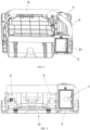
FIG. 2 is a perspective view of a sweeper base station according to an embodiment of the present disclosure. -
FIG. 3 is a front view of a sweeper base station according to an embodiment of the present disclosure. -
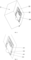
FIG. 4 is a perspective view of a dust collection assembly according to an embodiment of the present disclosure. -
FIG. 5 is a perspective view of an engagement portion according to an embodiment of the present disclosure. - In order to make the above objectives, features and advantages of the present disclosure to be more readily understood, a further description of the aspects of the present disclosure is provided below. It is noted that embodiments of the present disclosure and features of the embodiments may be combined with each other without conflict.
- In the following description, numerous specific details are set forth to provide a thorough understanding of the present disclosure, but the present disclosure may be practiced otherwise than as specifically described herein. It is to be understood that the embodiments in the description are only some embodiments of the present disclosure, instead of all embodiments.
- The terms "first," "second" and the like in the description and in the claims of the present disclosure are used to distinguish different objects, but not to describe a particular sequence of objects. For example, the first camera and the second camera are intended to distinguish different cameras, but not to describe a particular sequence of cameras.
- In the embodiments of the present disclosure, the wordings "exemplary," "for example" or the like are used to represent an example, instance, or illustration. Any embodiments or solutions described in the present disclosure as "exemplary" or "for example" are not necessarily to be construed as preferred or advantageous over other embodiments or solutions. Specifically, the use of the wordings "exemplary," "for example" or the like is intended to present concepts in a specific manner. Furthermore, in the description of the embodiments of the present disclosure, the meaning of "a plurality of' means two or more unless otherwise indicated.
- The existing dust collection assemblies usually need to be detached at the top of the base station, and therefore not only occupy the space at the top of the base station but also form visual shielding to the pipe ports in the base station, which is very easy to cause assembly deviation of the dust collection assemblies. Accordingly, the garbage sucked by the base station cannot be completely collected by the dust collection assemblies, thus contaminating the base station main body and contaminating the ground again when the dust collection assemblies are detached.
- In view of the above, according to the embodiments of the present disclosure, a dust collection assembly, a sweeper base station, a sweeper and a cleaning apparatus are provided, which can effectively solve the above technical problems.
- As shown in
FIGs. 1 to 5 , an embodiment of the present disclosure provides a cover body including a dust collection assemblymain body 3. The above dust collection assembly may be either a disposable and replaceable component or a recyclable component that is detachable for cleaning. The dust collection assemblymain body 3 is configured to be removably provided in a base stationmain body 10, and the dust collection assemblymain body 3 is detachable from a front surface of the base stationmain body 10. The front surface of the base stationmain body 10 is a surface where the sweeper body enters the base station or leaves the base station, and is usually arranged facing away from a wall. The dust collection assemblymain body 3 has a dust collection cavity formed in the dust collection assemblymain body 3 and anengagement portion 31 provided at a side surface of the dust collection assemblymain body 3. The side surface of the dust collection assemblymain body 3 particularly refers to a surface of the dust collection assemblymain body 3 perpendicular to an assembly and disassembly direction of the dust collection assemblymain body 3, and may face towards four directions, i.e., up, down, left, and right. Theengagement portion 31 is configured to be engaged with an engagement matching portion of the base stationmain body 10 and limited by the engagement matching portion. Accordingly, the engagement matching portion of the base stationmain body 10 is required to correspond to the position of the limit portion. Theabove engagement portion 31 and the engagement matching portion may achieve limit function and auxiliary assembly in a manner such as insertion, snap engagement, and magnetic suction engagement, allowing the dust collection assemblymain body 3 to be in communication with adust suction pipe 2 in the base stationmain body 10. Thus, the garbage in the sweeper body is sucked into the dust collection cavity of the dust collection assemblymain body 3 for storage. A user can clean or replace the dust collection assembly when the garbage fills up the dust collection cavity. - According to the dust collection assembly of the present embodiment, the
engagement portion 31 is disposed at the side surface of the dust collection assemblymain body 3. In this way, the engagement portion is configured to be engaged with the engagement matching portion of the base stationmain body 10 and limited by the engagement matching portion, and the dust collection assemblymain body 3 is prevented from forming visual shielding to theengagement portion 31, thereby facilitating to connect theengagement portion 31 to the engagement matching portion, and preventing leakage of garbage caused by misalignment of the dust collection cavity in the dust collection assemblymain body 3 and thedust suction pipe 2 of the base stationmain body 10 when abutting with each other. The dust collection assemblymain body 3 is detachably connected to the front surface of the base stationmain body 10, and therefore the setting position of the dust collection assemblymain body 3 can be more flexible to facilitate integration of thesweeper 100 with other home appliances. - In some embodiments, the dust collection assembly
main body 3 is a dust bag, and the above dust bag may be a cotton bag, a non-woven bag, a needle felt bag, and the like. Theengagement portion 31 is an insert provided at the dust collection assemblymain body 3. An opening of the dust bag may be either directly formed on the insert, or the insert may be arranged around the opening of the dust bag. The insert is configured to be engaged with the engagement matching portion. The above engagement matching portion may be directly disposed at a side wall of the accommodation cavity, or may be disposed at a corresponding position in the accommodation cavity by means of a support member. In an exemplary embodiment of the present disclosure, the local rigidity of the dust bag can be improved by providing the insert, such that the communication between the opening of the dust bag and thedust suction pipe 2 is more reliable, and occurrence of gaps and leakage of garbage during the abutting can be prevented. - Furthermore, the
engagement portion 31 includes afirst insert component 33 and asecond insert component 34. Thefirst insert component 33 is provided at the dust collection assemblymain body 3, and is configured to be engaged with the engagement matching portion. Thesecond insert component 34 is surrounded by thefirst insert component 33, and is configured to be engaged with thefirst insert component 33. In an exemplary embodiment of the present disclosure, an outer side of thefirst insert component 33 is configured to be engaged with the engagement matching portion, and an inner side of thefirst insert component 33 is configured to be engaged with thesecond insert component 34. Thefirst insert component 33 may be a frame structure of a gate shape, and thesecond insert component 34 is configured to be engaged with thefirst insert component 33 via an opening end of the frame structure. Thesecond insert component 34 has adust inlet 32 in communication with the dust collection cavity. In more detail, the engagement of thefirst insert component 33 with thesecond insert component 34 enables thesecond insert component 34 to slide with respect to thefirst insert component 33, such that the opening of the dust collection assemblymain body 3 can be in communication with thedust inlet 32 and shielded by thesecond insert component 34 based on different usage states. - In some more detailed embodiments, the
first insert component 33 has insertion slots formed at two opposite sides of thefirst insert component 33, and each of the insertion slots is configured to be engaged with thesecond insert component 34. In another exemplary embodiment of the present disclosure, in the frame structure of thesecond insert component 34, limit slots are formed at a side of thefirst insert component 33 opposite to the opening end, and the limit slots are configured to be engaged with an end of thesecond insert component 34. Further, a side of the insertion slot facing away from the dust collection assemblymain body 3 is provided with a plurality oflimit protrusions 331 symmetrically arranged at intervals. In an exemplary embodiment of the present disclosure, theabove limit protrusions 331 can limit thesecond insert component 34 in a direction perpendicular to thesecond insert component 34, to prevent thesecond insert component 34 from vertically swinging in a plane where the insertion slots of thefirst insert component 33 are located. In this way, the sealability between the opening of the dust collection cavity and thedust inlet 32 can be ensured, and the garbage is prevented from falling into the space between thesecond insert component 34 and the dust collection assemblymain body 3. - In other embodiments, a
first stopper 333 and asecond stopper 332 are sequentially arranged at each of the insertion slots in an insertion direction of thesecond insert component 34. In an exemplary embodiment of the present disclosure, the plurality oflimit protrusions 331 may be equivalent to thefirst stopper 333 and thesecond stopper 332. Thefirst stopper 333 is disposed close to an insertion end of thesecond insert component 34, and thesecond stopper 332 is disposed away from the insertion end of thesecond insert component 34. In another exemplary embodiment of the present disclosure, thedust inlet 32 is disposed in the middle or a rear part of thesecond insert component 34 in the insertion direction of thesecond insert component 34. Thesecond insert component 34 is provided with aprojection 341. Theprojection 341 is configured to allow thesecond insert component 34 to shield the opening of the dust collection cavity when theprojection 341 abuts with thefirst stopper 333, and to bring thedust inlet 32 into communication with the dust collection cavity when theprojection 341 abuts with thesecond stopper 332. In an exemplary embodiment of the present disclosure, when detaching the dust collection assembly, a user may apply a force to the dust collection assembly through thesecond insert component 34. When loading the dust collection assembly, the user needs to push thesecond insert component 34, and in this case, theprojection 341 is kept in abutment with thesecond stopper 332, such that thedust inlet 32 corresponds to the opening of the dust collection cavity. When removing the dust collection assembly, the user needs to pull thesecond insert component 34, and in this case, theprojection 341 is kept in abutment with thefirst stopper 333, such that thesecond insert component 34 covers the opening of the dust collection cavity, to close the dust collection cavity and prevent spillage of the garbage. - In a further exemplary embodiment of the present disclosure, the dust collection assembly
main body 3 is arranged at a right side of the front surface of the base stationmain body 10. Since the dust collection assembly requires manual cleaning by the user, it is possible to facilitate the user's operation by arranging the dust collection assemblymain body 3 at the right side of the base station main body. Moreover, theengagement portion 31 is arranged at the right side to facilitate the user to view the abutting position, facilitating the user's assembly of the dust collection assemblymain body 3 to enhance the user's experience. - The present disclosure provides a sweeper base station including a base station
main body 10 and the above-mentioned dust collection assembly. The base stationmain body 10 is provided with adust suction pipe 2, anair return pipe 6, and adust suction pump 5. The base stationmain body 10 has an accommodation cavity formed at a front surface of the base stationmain body 10, and the dust collection assemblymain body 3 is removably connected to the accommodation cavity. In another exemplary embodiment of the present disclosure, the accommodation cavity is provided with adust box 4, theabove dust box 4 may abut with the inner wall of the accommodation cavity, and the above engagement matching portion may be arranged at thedust box 4. Thedust suction pump 5 is provided at thedust suction pipe 2 or theair return pipe 6 to generate suction to suck out the garbage in the sweeper body. Thedust suction pipe 2 has a dust suction end configured to be in communication with a dust discharge port of the sweeper body and a dust outlet end located at a side wall of the accommodation cavity. Theair return pipe 6 has an air inlet end in communication with the accommodation cavity and an air outlet end configured to be in communication with an air inlet of the sweeper body. Thedust suction pipe 2 and theair return pipe 6 are provided to form an air circulation circuit, ensuring the air pressure balance in the sweeper body and making the garbage easier to be sucked out. - The embodiments of the present disclosure provide a sweeper base station of the
sweeper 100. The accommodation cavity for removably assembling the dust collection assemblymain body 3 is disposed at the front surface of the base stationmain body 10, and the dust outlet end of thedust suction pipe 2 is located at the side wall of the accommodation cavity, to cooperate with the detachable connection of the dust collection assemblymain body 3 and the accommodation cavity at the front surface of the base stationmain body 10, thereby avoiding occupying the top of the base stationmain body 10 for detaching the dust collection assembly. In this way, when the sweeper is integrated with other household appliances, the household appliances can be provided at the top of the base stationmain body 10 without interfering with the assembly and disassembly of the dust collection assembly. On the other hand, the dust collection assembly is removably provided at the front surface of the base stationmain body 10, and theengagement portion 31 of the dust collection assembly and the engagement matching portion of the base stationmain body 10 are respectively located at the side surfaces of the dust collection assemblymain body 3 and the accommodation cavity. Accordingly, the user can observe the assembly condition of theengagement portion 31 and the engagement matching portion from the front surface of thesweeper 100, thereby facilitating the user to abut the dust outlet end of thedust suction pipe 2 with the dust collection cavity in the dust collection assemblymain body 3. In addition, adust suction pump 5 is in communication with thedust suction pipe 2 or theair return pipe 6, and the suction force generated by thedust suction pump 5 enables thedust suction pipe 2 to suck out the garbage and dust in a dust collection container of the sweeper body and collect the same in the accommodation cavity of the dust collection assembly main body. Furthermore, an air flow enters the accommodation cavity, and is discharged through theair return pipe 6 after being filtered by fibers of the dust collection assembly main body. The air flow discharged through theair return pipe 6 can not only flow to the dust collection container of the sweeper body but also flow to the outside. If theair return pipe 6 leads into the dust collection container, the air flow can form circulation in the sweeper body and the base station. - In some embodiments, the
engagement portion 31 is disposed at a right side of the dust collection assemblymain body 3, and the dust outlet end of thedust suction pipe 2 is in communication with the dust collection cavity through theengagement portion 31. In an exemplary embodiment of the present disclosure, the accommodation cavity is disposed at the right side of the front surface of the base stationmain body 10. A user prefers to leave space at the right side of household appliances when the household appliances are placed, to facilitate opening and closing of doors of the household appliances. Therefore, it is more in line with the usage habit to arrange the accommodation cavity at the right side. The accommodation cavity may also be disposed at the left side, the upper side, or the lower side of the front surface of the base stationmain body 10 for some special customization requirements. - In other embodiments, at least part of the
dust suction pipe 2 is arranged around a top of the base stationmain body 10. In an exemplary embodiment of the present disclosure, the dust outlet end of the abovedust suction pipe 2 is in communication with the dust collection cavity at the right side of the dust collection assemblymain body 3, and the pipe body of thedust suction pipe 2 bypasses the top of the base stationmain body 10 and is in communication with the dust discharge port of the sweeper body. In another exemplary embodiment of the present disclosure, the dust discharge port of the above sweeper body is arranged towards the back surface of the base stationmain body 10. - In some embodiments, the sweeper base station further includes a shield portion. The above shield portion may be hinged to the base station
main body 10 at an end thereof, or the whole shield portion may be detached from the base stationmain body 10. The shield portion may be provided at the base stationmain body 10 in an openable or closable manner and configured to shield an opening of the accommodation cavity. In an exemplary embodiment of the present disclosure, the shield portion may be snapped or magnetically connected with the base stationmain body 10, or may be crimped to a slot of the base stationmain body 10 by a flexible structure. In another exemplary embodiment of the present disclosure, the shield portion is sealingly connected to the opening of the accommodation cavity. The shield portion is provided to shield the accommodation cavity and components (such as the dust collection assembly) in the accommodation cavity. On the one hand, the external garbage and dust are avoided from contaminating the accommodation cavity, and on the other hand, the visual integrity of the base stationmain body 10 can be improved to enhance the user experience. - In a particular application, the air inlet end of the
air return pipe 6 is located at an inner wall of an end of the accommodation cavity opposite to the opening, i.e., the air inlet end of theair return pipe 6 is disposed at the back surface of the accommodation cavity. In this way, the air flow that is mixed with garbage and enters the accommodation cavity through thedust suction pipe 2 can enter the dust collection cavity, and after the air flow is filtered by the dust collection assemblymain body 3, a clean air flow enters theair return pipe 6 to avoid repeated circulation of the garbage or dust between the base station and the sweeper body. In another exemplary embodiment of the present disclosure, the air inlet end of the aboveair return pipe 6 may also be disposed at the side wall of the accommodation cavity. In another exemplary embodiment of the present disclosure, the air inlet end of theair return pipe 6 may be arranged opposite the dust outlet end of thedust suction pipe 2. - In an embodiment, the
air return pipe 6 is arranged around the back surface of the base stationmain body 10. In another exemplary embodiment of the present disclosure, the air inlet of the sweeper body is arranged towards the back surface of the base stationmain body 10. Since the air inlet end of theair return pipe 6 is also arranged at the back surface of the accommodation cavity, theair return pipe 6 is arranged around the back surface of the base stationmain body 10 and is connected between the air inlet of the sweeper body and the accommodation cavity. Accordingly, an air supplying distance of theair return pipe 6 can be shortened, while bent ends of theair return pipe 6 are reduced and thus the air supply can be smoother. - In some more detailed embodiments, the air inlet end of the
air return pipe 6 is provided with afilter 7. In an exemplary embodiment of the present disclosure, theabove filter 7 may be disposed either in theair return pipe 6 or at the back surface of the accommodation cavity. In another embodiment, thefilter 7 may be disposed at thedust box 4, and thedust box 4 is then mounted in the accommodation cavity, to further filter the air flow entering theair return pipe 6. - In another exemplary embodiment of the present disclosure, the above accommodation cavity is provided with a
dust box 4. Thedust box 4 may be made of plastic or metal. Thedust box 4 may be fixedly disposed in the accommodation cavity, and abut with the base station body. Theabove dust box 4 may be a continuous structure, or may be a hollowed-out structure or a frame structure. A cavity is formed inside thedust box 4 to assemble a dust collection assembly. Theabove filter 7 and an engagement matching portion may be provided at thedust box 4 without processing the inside of the accommodation cavity, to simplify the design and processing process of the accommodation cavity, thereby reducing the production cost of thesweeper 100. - The present disclosure provides a
sweeper 100 including a sweeper body and the above-mentioned sweeper base station. The sweeper base station is adapted to accommodate the sweeper body, and the above sweeper base station can automatically charge the sweeper body entering the sweeper base station and automatically clean the sweeper body. The sweeper body has an air inlet and a dust discharge port, and the air inlet and the dust discharge port are in communication with theair outlet 8 and thedust suction port 9 arranged at the base stationmain body 10, respectively. The above dust discharge port is configured to discharge garbage in a dust collection container of thesweeper 100. In another exemplary embodiment of the present disclosure, the above air inlet is configured to introduce filtered clean air into the dust collection container. If the interior of the dust collection container is in communication with the atmosphere during dust discharge, the air inlet can open to the external environment. The air inlet is in communication with the air outlet end of theair return pipe 6, and the dust discharge port is in communication with the dust suction end of thedust suction pipe 2. - Furthermore, the air inlet and the dust discharge port are arranged at two opposite sides of the sweeper body, i.e., the air inlet and the dust discharge port are both in communication with the dust collection container of the sweeper body. The air flow entering the air inlet can blow away the garbage in the dust collection container so that the dust discharge port collects the garbage. The air inlet and the dust discharge port are arranged at the two opposite sides of the dust collection container, such that the air flow passes through the whole dust collection container, avoiding local accumulation of the garbage in the dust collection container to occupy the volume of the dust collection container. Accordingly, the
air outlet 8 and thedust suction port 9 provided at the base stationmain body 10 should correspond to the positions of the air inlet and the dust discharge port, respectively. - The present disclosure provides a cleaning apparatus including the above-described
sweeper 100 and awashing device 200 disposed above thesweeper 100. Since the cleaning apparatus includes both thesweeper 100 and thewashing device 200, thesweeper 100 is configured to have a flat cuboid configuration, to save space, reduce the center of gravity of the cleaning apparatus, and improve the overall stability of the cleaning apparatus. The dust collection assembly is disposed at the front surface of the base stationmain body 10, and therefore it is convenient for a user to remove the dust collection assembly for replacement or cleaning. Further, when the dust collection assembly is assembled, theengagement portion 31 and the engagement matching portion can be visible, such that the leakage of garbage caused by misalignment of thedust inlet 32 and the dust outlet end of thedust suction pipe 2 can be prevented, which is beneficial to keeping the interior of the base stationmain body 10 clean to enhance the user experience. - The
sweeper 100 and the cleaning apparatus of the present embodiment include the above-mentioned sweeper base station and the dust collection assembly included in the sweeper base station. The dust collection assembly has the advantage of being removed without occupying the top space of the sweeper base station, which facilitates to combine with other household appliances, and theengagement portion 31 is visible during the assembly. Therefore, thesweeper 100 and the cleaning apparatus also have better quality and user experience. - Various technical features of the above-mentioned embodiments may be combined in any combination, and not all the possible combinations of each of the technical features in the above embodiments are described in order to make the description concise. However, as long as there is no contradiction between the combinations of these technical features, they should be considered as the scope of the description.
- The above embodiments are indicative of only some embodiments of the present disclosure, whose descriptions are more specific and detailed, but are not to be construed as limiting to the scope of the present disclosure. It should be noted that several variations and modifications can be made by those skilled in the art without departing from the scope of the present disclosure, which is within the scope of the present disclosure. Accordingly, the scope of the present disclosure is as set forth in the claims below.
- According to the dust collection assembly, the sweeper base station, the sweeper and the cleaning apparatus of the present disclosure, the
engagement portion 31 is disposed at the side surface of the dust collection assemblymain body 3, the engagement portion is configured to be engaged with the engagement matching portion of the base stationmain body 10 and limited by the engagement matching portion, and the dust collection assemblymain body 3 is prevented from forming visual shielding to theengagement portion 31, thereby facilitating to connect theengagement portion 31 to the engagement matching portion. In this way, leakage of the garbage caused by misalignment of the dust collection cavity in the dust collection assemblymain body 3 and thedust suction pipe 2 of the base stationmain body 10 during abutting can be prevented. The dust collection assemblymain body 3 is configured to be detachably connected to the front surface of the base stationmain body 10, such that the setting position of the dust collection assemblymain body 3 can be more flexible to integrate thesweeper 100 with other home appliances, which has strong industrial applicability.
Claims (16)
- A dust collection assembly, characterized in that:the dust collecting component comprises a dust collection assembly main body (3) configured to be removably provided in a base station main body (10), the dust collection assembly main body (3) being detachable from a front surface of the base station main body (10); andthe dust collection assembly main body (3) has a dust collection cavity formed in the dust collection assembly main body (3) and an engagement portion (31) provided at a side surface of the dust collection assembly main body (3), and the engagement portion (31) is configured to be engaged with an engagement matching portion of the base station main body (10) and limited by the engagement matching portion, allowing the dust collection assembly main body (3) to be in communication with a dust suction pipe (2) in the base station main body.
- The dust collection assembly according to claim 1, wherein the dust collection assembly main body (3) is a dust bag, and wherein the engagement portion (31) is an insert provided at the dust collection assembly main body (3), the insert being configured to be engaged with the engagement matching portion.
- The dust collection assembly according to claim 2, wherein the engagement portion (31) comprises:a first insert component (33) provided at the dust collection assembly main body (3) and configured to be engaged with the engagement matching portion; anda second insert component (34) surrounded by the first insert component (33) and configured to be engaged with the first insert component (33), the second insert component (34) having a dust inlet (32) in communication with the dust collection cavity.
- The dust collection assembly according to claim 3, wherein:the first insert component (33) has insertion slots formed at two opposite sides of the first insert component (33), each of the insertion slots being configured to be engaged with the second insert component (34); anda side of the insertion slot facing away from the dust collection assembly main body (3) is provided with a plurality of limit protrusions (331) symmetrically arranged at intervals, the plurality of limit protrusions (331) being configured to abut with the second insert component (34).
- The dust collection assembly according to claim 4, wherein:in an insertion direction of the second insert component (34), a first stopper (333) and a second stopper (332) are sequentially arranged at each of the insertion slots; andthe second insert component (34) is provided with a projection (341), the projection (341) being configured to allow the second insert component (34) to shield an opening of the dust collection cavity when the projection (341) abuts with the first stopper (333), and to bring the dust inlet (32) into communication with the dust collection cavity when the projection (341) abuts with the second stopper (332).
- The dust collection assembly according to any one of claims 1 to 5, wherein the dust collection assembly main body (3) is arranged at a right side of the front surface of the base station main body (10).
- A sweeper base station, comprising a base station main body (10) and the dust collection assembly according to any one of claims 1 to 6,wherein the base station main body (10) is provided with a dust suction pipe (2), an air return pipe (6), and a dust suction pump (5);wherein the base station main body (10) has an accommodation cavity formed at a front surface of the base station main body (10), the dust collection assembly main body (3) being removably connected to the accommodation cavity;wherein the dust suction pump (5) is disposed at the dust suction pipe (2) or the air return pipe (6);wherein the dust suction pipe (2) has a dust suction end configured to be in communication with a dust discharge port of a sweeper body and a dust outlet end located at a side wall of the accommodation cavity; andwherein the air return pipe (6) has an air inlet end in communication with the accommodation cavity and an air outlet end configured to be in communication with an air inlet of the sweeper body.
- The sweeper base station according to claim 7, wherein:the engagement portion (31) is disposed at a right side of the dust collection assembly main body (3); andthe dust outlet end of the dust suction pipe (2) is in communication with the dust collection cavity through the engagement portion (31).
- The sweeper base station according to claim 8, wherein at least part of the dust suction pipe (2) is arranged around a top of the base station main body (10).
- The sweeper base station according to claim 7, further comprising:
a shield portion provided at the base station main body (10) in an openable or closable manner and configured to shield an opening of the accommodation cavity. - The sweeper base station according to claim 7, wherein the air inlet end of the air return pipe (6) is located at an inner wall of an end of the accommodation cavity opposite to the opening.
- The sweeper base station according to claim 11, wherein the air return pipe (6) is arranged around a back surface of the base station main body (10).
- The sweeper base station according to claim 7, wherein the air inlet end of the air return pipe (6) is provided with a filter (7).
- A sweeper, comprising a sweeper body and the sweeper base station according to any one of claims 7 to 13,wherein the sweeper base station is configured to accommodate the sweeper body; andwherein the sweeper body has an air inlet and a dust discharge port, the air inlet being in communication with the air outlet end of the air return pipe (6), and the dust discharge port being in communication with the dust suction end of the dust suction pipe (2).
- The sweeper according to claim 14, wherein the air inlet and the dust discharge port are arranged at two opposite sides of the sweeper body.
- A cleaning apparatus, comprising a washing device (200) and the sweeper according to claim 14 or 15, wherein the washing device (200) is disposed above the sweeper.
Applications Claiming Priority (3)
| Application Number | Priority Date | Filing Date | Title |
|---|---|---|---|
| CN202223212852.6U CN218922463U (en) | 2022-11-30 | 2022-11-30 | Dust collection piece, base station of sweeper, sweeper and cleaning device |
| CN202211527091.5A CN117017135A (en) | 2022-11-30 | 2022-11-30 | Dust collection piece, base station of sweeper, sweeper and cleaning device |
| PCT/CN2023/113880 WO2024113978A1 (en) | 2022-11-30 | 2023-08-18 | Dust collector, sweeper base station, sweeper, and cleaning device |
Publications (2)
| Publication Number | Publication Date |
|---|---|
| EP4400022A1 true EP4400022A1 (en) | 2024-07-17 |
| EP4400022A4 EP4400022A4 (en) | 2024-11-13 |
Family
ID=89119248
Family Applications (1)
| Application Number | Title | Priority Date | Filing Date |
|---|---|---|---|
| EP23814343.2A Pending EP4400022A4 (en) | 2022-11-30 | 2023-08-18 | DUST COLLECTOR, SWEEPER BASE STATION, SWEEPER AND CLEANING DEVICE |
Country Status (3)
| Country | Link |
|---|---|
| US (1) | US20250082149A1 (en) |
| EP (1) | EP4400022A4 (en) |
| WO (1) | WO2024113978A1 (en) |
Family Cites Families (14)
| Publication number | Priority date | Publication date | Assignee | Title |
|---|---|---|---|---|
| US8528157B2 (en) * | 2006-05-19 | 2013-09-10 | Irobot Corporation | Coverage robots and associated cleaning bins |
| CN113040649B (en) * | 2019-12-28 | 2022-12-06 | 尚科宁家(中国)科技有限公司 | Dust collecting station for sweeping robot |
| CN111345752B (en) * | 2020-03-12 | 2022-05-03 | 深圳市银星智能科技股份有限公司 | Robot maintenance station and robot cleaning system |
| US11529034B2 (en) * | 2020-07-20 | 2022-12-20 | Omachron lntellectual Property Inca | Evacuation station for a mobile floor cleaning robot |
| CN213371774U (en) * | 2020-09-11 | 2021-06-08 | 深圳市银星智能科技股份有限公司 | Garbage recycling base station and cleaning system |
| CN113062091A (en) * | 2021-04-19 | 2021-07-02 | 创维电器股份有限公司 | Clothes dryer or washing machine base with sweeping robot |
| CN113796776A (en) * | 2021-09-24 | 2021-12-17 | 深圳市银星智能科技股份有限公司 | Dust collecting device and cleaning system |
| CN217285658U (en) * | 2021-11-29 | 2022-08-26 | 珠海格力电器股份有限公司 | Drawer type dust collecting base station and cleaning robot |
| CN120323885A (en) * | 2021-12-31 | 2025-07-18 | 北京石头世纪科技股份有限公司 | Dust bag, self-cleaning dust collection base and dust collection system |
| CN114886344A (en) * | 2022-03-28 | 2022-08-12 | 安克创新科技股份有限公司 | Base station and cleaning system |
| CN114921932B (en) * | 2022-05-17 | 2025-01-28 | 无锡小天鹅电器有限公司 | Base and clothing processing device |
| CN115012168B (en) * | 2022-05-17 | 2025-04-25 | 无锡小天鹅电器有限公司 | Base assembly and clothing processing device |
| CN114855426A (en) * | 2022-05-17 | 2022-08-05 | 无锡小天鹅电器有限公司 | Base assembly, base device and clothes treatment equipment |
| CN218922463U (en) * | 2022-11-30 | 2023-04-28 | 无锡小天鹅电器有限公司 | Dust collection piece, base station of sweeper, sweeper and cleaning device |
-
2023
- 2023-08-18 WO PCT/CN2023/113880 patent/WO2024113978A1/en not_active Ceased
- 2023-08-18 EP EP23814343.2A patent/EP4400022A4/en active Pending
- 2023-08-18 US US18/569,514 patent/US20250082149A1/en active Pending
Also Published As
| Publication number | Publication date |
|---|---|
| US20250082149A1 (en) | 2025-03-13 |
| WO2024113978A1 (en) | 2024-06-06 |
| EP4400022A4 (en) | 2024-11-13 |
Similar Documents
| Publication | Publication Date | Title |
|---|---|---|
| AU2020420350B2 (en) | Station | |
| US20050015920A1 (en) | Dust receptacle of robot cleaner and a method for removing dust collected therein | |
| US20250064281A1 (en) | Dust bag, self-cleaning dust collection seat and dust collection system | |
| EP3741278A1 (en) | Dust collection box and sweeping robot | |
| CN210871311U (en) | Dust collecting box and sweeping robot thereof | |
| GB2388769A (en) | A vacuum cleaner compatible with both a disposable and reusable filter | |
| CN218922463U (en) | Dust collection piece, base station of sweeper, sweeper and cleaning device | |
| US20230371766A1 (en) | Station for cleaner | |
| CN217365692U (en) | Water tank assembly and cleaning equipment | |
| KR20210130461A (en) | Stand for Cleaner | |
| US20250082149A1 (en) | Dust collection assembly, sweeper base station, sweeper, and cleaning apparatus | |
| US20250057381A1 (en) | Self-cleaning dust collection base and dust collection system | |
| EP4458240A1 (en) | Self-cleaning dust-collecting base and dust-collecting system | |
| JPH04218121A (en) | Intake nozzle assemblage for suction cleaner with water tank | |
| CN215738716U (en) | Cyclone separator and dust collection recycling station | |
| CN216854604U (en) | Dust bag, self-cleaning dust collecting seat and dust collecting system | |
| CN216495158U (en) | Self-cleaning dust collecting seat and dust collecting system | |
| CN216907810U (en) | Dust collection assembly and cleaning robot | |
| CN117017135A (en) | Dust collection piece, base station of sweeper, sweeper and cleaning device | |
| CN218009547U (en) | Cleaning robot | |
| CN215534013U (en) | Cleaning device detachable machine of sweeping floor | |
| CN223438437U (en) | Cleaning equipment and automatic cleaning systems | |
| CN219140862U (en) | Smoke machine | |
| CN223585850U (en) | Cleaning system | |
| CN210124713U (en) | Dust accumulation base and cleaning equipment assembly having the same |
Legal Events
| Date | Code | Title | Description |
|---|---|---|---|
| STAA | Information on the status of an ep patent application or granted ep patent |
Free format text: STATUS: UNKNOWN |
|
| STAA | Information on the status of an ep patent application or granted ep patent |
Free format text: STATUS: THE INTERNATIONAL PUBLICATION HAS BEEN MADE |
|
| PUAI | Public reference made under article 153(3) epc to a published international application that has entered the european phase |
Free format text: ORIGINAL CODE: 0009012 |
|
| STAA | Information on the status of an ep patent application or granted ep patent |
Free format text: STATUS: REQUEST FOR EXAMINATION WAS MADE |
|
| 17P | Request for examination filed |
Effective date: 20231208 |
|
| AK | Designated contracting states |
Kind code of ref document: A1 Designated state(s): AL AT BE BG CH CY CZ DE DK EE ES FI FR GB GR HR HU IE IS IT LI LT LU LV MC ME MK MT NL NO PL PT RO RS SE SI SK SM TR |
|
| A4 | Supplementary search report drawn up and despatched |
Effective date: 20241016 |
|
| RIC1 | Information provided on ipc code assigned before grant |
Ipc: A47L 11/24 20060101ALI20241010BHEP Ipc: A47L 11/40 20060101AFI20241010BHEP |
|
| DAV | Request for validation of the european patent (deleted) | ||
| DAX | Request for extension of the european patent (deleted) |