EP4399992A1 - Protective case and portable electronic device - Google Patents
Protective case and portable electronic device Download PDFInfo
- Publication number
- EP4399992A1 EP4399992A1 EP23186700.3A EP23186700A EP4399992A1 EP 4399992 A1 EP4399992 A1 EP 4399992A1 EP 23186700 A EP23186700 A EP 23186700A EP 4399992 A1 EP4399992 A1 EP 4399992A1
- Authority
- EP
- European Patent Office
- Prior art keywords
- buffer
- protective case
- device body
- pads
- portable electronic
- Prior art date
- Legal status (The legal status is an assumption and is not a legal conclusion. Google has not performed a legal analysis and makes no representation as to the accuracy of the status listed.)
- Pending
Links
Images




Classifications
-
- A—HUMAN NECESSITIES
- A45—HAND OR TRAVELLING ARTICLES
- A45C—PURSES; LUGGAGE; HAND CARRIED BAGS
- A45C11/00—Receptacles for purposes not provided for in groups A45C1/00-A45C9/00
-
- G—PHYSICS
- G06—COMPUTING OR CALCULATING; COUNTING
- G06F—ELECTRIC DIGITAL DATA PROCESSING
- G06F1/00—Details not covered by groups G06F3/00 - G06F13/00 and G06F21/00
- G06F1/16—Constructional details or arrangements
- G06F1/1613—Constructional details or arrangements for portable computers
- G06F1/1633—Constructional details or arrangements of portable computers not specific to the type of enclosures covered by groups G06F1/1615 - G06F1/1626
- G06F1/1656—Details related to functional adaptations of the enclosure, e.g. to provide protection against EMI, shock, water, or to host detachable peripherals like a mouse or removable expansions units like PCMCIA cards, or to provide access to internal components for maintenance or to removable storage supports like CDs or DVDs, or to mechanically mount accessories
-
- A—HUMAN NECESSITIES
- A45—HAND OR TRAVELLING ARTICLES
- A45C—PURSES; LUGGAGE; HAND CARRIED BAGS
- A45C13/00—Details; Accessories
- A45C13/36—Reinforcements for edges, corners, or other parts
-
- F—MECHANICAL ENGINEERING; LIGHTING; HEATING; WEAPONS; BLASTING
- F16—ENGINEERING ELEMENTS AND UNITS; GENERAL MEASURES FOR PRODUCING AND MAINTAINING EFFECTIVE FUNCTIONING OF MACHINES OR INSTALLATIONS; THERMAL INSULATION IN GENERAL
- F16F—SPRINGS; SHOCK-ABSORBERS; MEANS FOR DAMPING VIBRATION
- F16F15/00—Suppression of vibrations in systems; Means or arrangements for avoiding or reducing out-of-balance forces, e.g. due to motion
- F16F15/02—Suppression of vibrations of non-rotating, e.g. reciprocating systems; Suppression of vibrations of rotating systems by use of members not moving with the rotating systems
- F16F15/023—Suppression of vibrations of non-rotating, e.g. reciprocating systems; Suppression of vibrations of rotating systems by use of members not moving with the rotating systems using fluid means
-
- F—MECHANICAL ENGINEERING; LIGHTING; HEATING; WEAPONS; BLASTING
- F16—ENGINEERING ELEMENTS AND UNITS; GENERAL MEASURES FOR PRODUCING AND MAINTAINING EFFECTIVE FUNCTIONING OF MACHINES OR INSTALLATIONS; THERMAL INSULATION IN GENERAL
- F16F—SPRINGS; SHOCK-ABSORBERS; MEANS FOR DAMPING VIBRATION
- F16F15/00—Suppression of vibrations in systems; Means or arrangements for avoiding or reducing out-of-balance forces, e.g. due to motion
- F16F15/02—Suppression of vibrations of non-rotating, e.g. reciprocating systems; Suppression of vibrations of rotating systems by use of members not moving with the rotating systems
- F16F15/04—Suppression of vibrations of non-rotating, e.g. reciprocating systems; Suppression of vibrations of rotating systems by use of members not moving with the rotating systems using elastic means
-
- F—MECHANICAL ENGINEERING; LIGHTING; HEATING; WEAPONS; BLASTING
- F16—ENGINEERING ELEMENTS AND UNITS; GENERAL MEASURES FOR PRODUCING AND MAINTAINING EFFECTIVE FUNCTIONING OF MACHINES OR INSTALLATIONS; THERMAL INSULATION IN GENERAL
- F16F—SPRINGS; SHOCK-ABSORBERS; MEANS FOR DAMPING VIBRATION
- F16F15/00—Suppression of vibrations in systems; Means or arrangements for avoiding or reducing out-of-balance forces, e.g. due to motion
- F16F15/02—Suppression of vibrations of non-rotating, e.g. reciprocating systems; Suppression of vibrations of rotating systems by use of members not moving with the rotating systems
- F16F15/04—Suppression of vibrations of non-rotating, e.g. reciprocating systems; Suppression of vibrations of rotating systems by use of members not moving with the rotating systems using elastic means
- F16F15/08—Suppression of vibrations of non-rotating, e.g. reciprocating systems; Suppression of vibrations of rotating systems by use of members not moving with the rotating systems using elastic means with rubber springs ; with springs made of rubber and metal
-
- G—PHYSICS
- G06—COMPUTING OR CALCULATING; COUNTING
- G06F—ELECTRIC DIGITAL DATA PROCESSING
- G06F1/00—Details not covered by groups G06F3/00 - G06F13/00 and G06F21/00
- G06F1/16—Constructional details or arrangements
- G06F1/1613—Constructional details or arrangements for portable computers
- G06F1/1628—Enclosures for carrying portable computers with peripheral devices, e.g. cases for a laptop and a printer
-
- H—ELECTRICITY
- H04—ELECTRIC COMMUNICATION TECHNIQUE
- H04B—TRANSMISSION
- H04B1/00—Details of transmission systems, not covered by a single one of groups H04B3/00 - H04B13/00; Details of transmission systems not characterised by the medium used for transmission
- H04B1/38—Transceivers, i.e. devices in which transmitter and receiver form a structural unit and in which at least one part is used for functions of transmitting and receiving
- H04B1/3827—Portable transceivers
- H04B1/3888—Arrangements for carrying or protecting transceivers
-
- H—ELECTRICITY
- H04—ELECTRIC COMMUNICATION TECHNIQUE
- H04M—TELEPHONIC COMMUNICATION
- H04M1/00—Substation equipment, e.g. for use by subscribers
- H04M1/02—Constructional features of telephone sets
- H04M1/18—Telephone sets specially adapted for use in ships, mines, or other places exposed to adverse environment
-
- A—HUMAN NECESSITIES
- A45—HAND OR TRAVELLING ARTICLES
- A45C—PURSES; LUGGAGE; HAND CARRIED BAGS
- A45C11/00—Receptacles for purposes not provided for in groups A45C1/00-A45C9/00
- A45C11/002—Receptacles for purposes not provided for in groups A45C1/00-A45C9/00 for storing portable handheld communication devices, e.g. pagers or smart phones
-
- A—HUMAN NECESSITIES
- A45—HAND OR TRAVELLING ARTICLES
- A45C—PURSES; LUGGAGE; HAND CARRIED BAGS
- A45C11/00—Receptacles for purposes not provided for in groups A45C1/00-A45C9/00
- A45C11/003—Receptacles for purposes not provided for in groups A45C1/00-A45C9/00 for storing portable computing devices, e.g. laptops, tablets or calculators
-
- A—HUMAN NECESSITIES
- A45—HAND OR TRAVELLING ARTICLES
- A45C—PURSES; LUGGAGE; HAND CARRIED BAGS
- A45C13/00—Details; Accessories
- A45C13/02—Interior fittings; Means, e.g. inserts, for holding and packing articles
- A45C2013/025—Interior fittings; Means, e.g. inserts, for holding and packing articles for holding portable computers or accessories therefor
Definitions
- the present disclosure relates to a protective case, more particularly to a protective case mounted on a portable electronic device.
- Portable electronic devices such as smartphones, tablet computers or notebook computers, have become indispensable electronic products in daily life since the portable electronic devices are easy to carry so that users can do various tasks matters via the portable electronic devices anytime and anywhere.
- most of the portable electronic devices are not shock resistant. If the fragile sides or corners of the portable electronic devices hit the ground or other objects, the display panel and internal electronic components of the portable electronic devices can be easily damaged. Therefore, some portable electronic devices have a basic shockproof design.
- the present disclosure provides a protective case to protect sides of a portable electronic device, so as to protect provide comprehensive protection for the portable electronic device, thereby preventing the portable electronic device from being damaged due to mechanical shocks.
- One embodiment of the present disclosure provides a protective case including a plurality of buffer pads and a plurality of connectors.
- the plurality of buffer pads together surround and form an accommodation space.
- Each of the plurality of buffer pads includes an elastic clamping part.
- the elastic clamping part includes an upper buffer plate, a lower buffer plate and a side buffer plate. Two opposite sides of the side buffer plate are connected to the upper buffer plate and the lower buffer plate, respectively, and each of the upper buffer plates, the lower buffer plates and the side buffer plates together forms a clamping space.
- An exposed space portion is formed between any two of the plurality of buffer pads which are adjacent to each other.
- the plurality of connectors are located in the exposed space portions, respectively, and two ends of each of the plurality of connectors are connected to any two of the plurality of buffer pads which are adjacent to each other, respectively .
- a portable electronic device including a device body and a protective case.
- the protective case is mounted on the device body, and includes a plurality of buffer pads and a plurality of connectors.
- the plurality of plurality of buffer pads together form an accommodation space.
- the device body is accommodated in the accommodation space.
- Each of the plurality of buffer pads comprises an elastic clamping part.
- the elastic clamping part comprises an upper buffer plate, a lower buffer plate and a side buffer plate. Two opposite sides of the side buffer plate are connected to the upper buffer plate and the lower buffer plate, respectively, and each of the upper buffer plates, the lower buffer plates and the side buffer plates together forms a clamping space. A side of the body is clamped by the elastic clamping part in the clamping space.
- the exposed space portion is formed between any two of the plurality of buffer pads which are adjacent to each other.
- the plurality of connectors are located in the exposed space portions, respectively, and two ends of each of the plurality of connectors are connected to any two of the plurality of buffer pads which are adjacent to each other, respectively .
- the exposed space portions expose corners of the device body.
- the protective case since the protective case provides additional protection to the sides of the body, if the side of the device body hits the ground or other objects, the buffer pads of the protective case may buffer and absorb the shock. Therefore, in addition to the corners of device body with the function of the shockproof, the protective case may protect the sides of the portable electronic device so as to provide comprehensive protection for the portable electronic device, thereby preventing the portable electronic device from being damaged due to mechanical shocks.
- FIG. 1 is a perspective view of a portable electronic device 1 in accordance with an embodiment of the present disclosure
- FIG. 2 is an exploded view of the portable electronic device 1 in FIG. 1
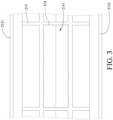
- FIG. 3 is a plane view of some buffer pads 21 in FIG. 1 .
- the portable electronic device 1 includes a device body 10 and a protective case 20.
- the device body 10 is, for example, a tablet computer, but the present disclosure is not limited thereto. In other embodiments, the device body may be, for example, at least a part of a notebook computer or a smartphone.
- the device body 10 has a front surface 11, a back surface 12 and four side surfaces 13. The front surface 11 and the back surface 12 are opposite to each other and are connected via the four side surfaces 13.
- the protective case 20 is mounted on the device body 10 and includes four buffer pads 21 and four connectors 22.
- the four buffer pads 21 are, for example, made of silicon or other elastic material, and together surround and form an accommodation space 211.
- the device body 10 is accommodated in the accommodation space 211.
- Each of the buffer pads 21 includes an elastic clamping part 212, a plurality of buffer components 214 and a plurality of dividing components 215.
- the elastic clamping part 212 includes an upper buffer plate 2121, a lower buffer plate 2122 and a side buffer plate 2123. Two opposite sides of the side buffer plate 2123 are connected to the upper buffer plate 2121 and the lower buffer plate 2122, respectively, and the upper buffer plate 2121, the lower buffer plate 2122 and the side buffer plate 2123 together form a clamping space 2124. A side of the device body 10 is clamped by the elastic clamping part 212 in the clamping space 2124.
- the plurality of buffer components 214 are located in the clamping spaces 2124 and are disposed at a side of the elastic clamping parts 212.
- the plurality of buffer components 214 physically contact the side of the device body 10. That is, the plurality of buffer components 214 physically contact the side of the device body 10 to form a plurality of airbags so as to buffer and absorb the mechanical shock to the device body 10 when the device body 10 is hit or, for example, falls on a hard surface.
- the detailed structural relationship between the device body 10 and the buffer components 214 will be described later.
- the plurality of dividing components 215 are located in the clamping spaces 2124 and protrude from the sides of the elastic clamping parts 212.
- the plurality of dividing components 215 divide each of the clamping spaces 2124 into a plurality of segments.
- the plurality of buffer components 214 are located in the plurality of segments.
- the plurality of dividing components 215 divide each of the plurality of buffer components 214 into a plurality of small airbags so as to ensure the buffering effect by reducing the overall size of the plurality of buffer components 214.
- An exposed space portion 213 is formed between each of all adjacent two buffer pads 21.
- the four connectors 22 are located in the four exposed space portions 213, respectively.
- Each of the connectors 22 is, for example, a rope structure.
- the four connectors 22 are, for example, made of plastic. Two ends of each of the connectors 22 are connected to two of the buffer pads 21 adjacent thereto, respectively. For example, the two ends of each of the connectors 22 are connected to two of the buffer pads 21 adjacent thereto via binding or other means.
- the four exposed space portions 213 expose four corners 14 of the device body 10, respectively. Since the four corners 14 of the device body 10 have shockproof function already, the protective case 20 merely needs to protect the four sides surfaces 13 of the device body 10 and does not need to protect the four corners 14, and the protective case 20 may expose the four corners 14 of the device body 10.
- the four buffer pads 21 of the protective case 20 may protect the sides of the device body 10.
- the four buffer pads 21 may buffer and absorb the shock so as to prevent the device body 10 from being damaged.
- the quantities of the buffer pads 21 and the connectors 22 of the protective case 20 are four, respectively.
- the two ends of each of the connectors 22 are connected to two buffer pads 21 adjacent thereto, respectively, and the device body 10 such as a tablet computer may be accommodated in the accommodation space 211 together surrounded and formed by the four buffer pads 21, but the present disclosure is not limited thereto.
- the quantities of the buffer pads and the connectors of the protective case may be three, respectively.
- the two ends of each of the connectors are connected to two buffer pads adjacent thereto, respectively, and the device body such as a display or a main body of a notebook computer may be accommodated in the accommodation space together surrounded and formed by the three buffer pads.
- one of the side buffer plates 2123 of the four buffer pads 21 has a through hole 21231, which exposes a port of the device body 10 so that external cables can be plugged into the port.
- the quantity of the through hole 21231 is one, and the through hole 21231 is located at one of the side buffer plates 2123 of the four buffer pads 21, but the present disclosure is not limited thereto. In other embodiments, the quantity of the through holes may be more than one, and the through holes are located at one or more of the side buffer plates of the four buffer pads, respectively.
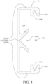
- FIG. 4 is a cross-sectional view of buffer pads 21 in FIG. 1
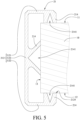
- FIG. 5 is a cross-sectional view of a side of a device body 10 located in a clamping space 2124 in FIG. 1 .
- the plurality of buffer components 214 are disposed at the upper buffer plate 2121, the lower buffer plate 2122 and the side buffer plate 2123 of each of the elastic clamping parts 212, respectively, and are located in the plurality of clamping spaces 2124.
- the plurality of buffer components 214 are not connected to one another.
- a cross-section of each of the plurality of buffer components 214 are, for example, V-shaped, U-shaped or semicircular.
- Each of the plurality of buffer components 214 has an opening 2141. An area of each of the openings 2141 is less than 1 cm 2 .
- the device body 10 is located in the clamping spaces 2124, and the plurality of buffer components 214 physically contact the front surface 11, back surface 12 and side surfaces 13 of the device body 10, respectively so as to close the openings 2141 to form the plurality of airbags.
- the plurality of buffer components 214 tightly contact the side of the device body 10 which is hit, such that an inflation state may be formed between the plurality of buffer components 214 and the side of the device body 10 being hit via the pressure caused by the shock to buffer and absorb the shock to prevent the device body 10 from being damaged.
- FIG. 6 is a partial plane view of the portable electronic device 1 in FIG. 1 .
- the four side surfaces 13 of the device body 10 are connected to the four buffer pads 21, respectively.
- a length D1 of each of the four buffer pads 21 protruding from the side surface 13 is less than a length D2 of the any one corner 14 protruding from the device body 10. Accordingly, since the four corners 14 of the device body 10 protrude outwards more than the four buffer pads 21, the protective case 20 may expose the four corners 14 of the device body 10.
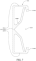
- FIG. 7 is a cross-sectional view of a buffer pad 21A of the protective case 20 in accordance with another embodiment of the present disclosure.
- a plurality of buffer components 214A1 of each of the four buffer pads 21A located at the side buffer plate 2123 are connected to a plurality of buffer components 214A2 of each of the four buffer pads 21A located at the upper buffer plate 2121 and a plurality of buffer components 214A2 of each of the four buffer pads 21A located at the lower buffer plate 2122, respectively, and each of the plurality of buffer components 214A1, 214A2 has an opening, respectively.
- an inflation state may be formed between the plurality of buffer components 214A1, 214A2 and the side of the device body 10 being hit via the pressure caused by the shock to buffer and absorb the shock to prevent the device body 10 from being damaged.
- FIG. 8 is a cross-sectional view of a buffer pad 21B of the protective case 20 in accordance with another embodiment of the present disclosure.
- the plurality of buffer components 214B1 located at the side buffer plate 2123 of each of the four buffer pads 21B are connected to the plurality of buffer components 214B2 located at the upper buffer plate 2121 of each of the four buffer pads 21B and the plurality of buffer components 214B2 located at the lower buffer plate 2122 of each of the four buffer pads 21B.
- an inflation state may be formed between the plurality of buffer components 214B1, 214B2 and the side of the device body 10 being hit via the pressure caused by the shock to buffer and absorb the shock to prevent the device body 10 from being damaged.
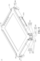
- FIG. 9 is a perspective view of a portable electronic device 1C in accordance with another embodiment of the present disclosure
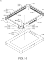
- FIG. 10 is an exploded view of the portable electronic device 1C in FIG. 9 .
- the portable electronic device 1C in this embodiment is similar to the portable electronic device 1 in FIG. 1 . Therefore, the differences in this embodiment will be described below, and the similarities will not be repeated.
- an exposed space portion 213 is formed between each of all adjacent two buffer pads 21 of the portable electronic device 1C.
- the four connectors 22C are located in the four exposed space portions 213, respectively.
- Each of the connectors 22C is, for example, a mesh structure.
- the four connectors 22C are, for example, made of plastic.
- Each of the connectors 22C includes a frame 221 and a plurality of connecting parts 222.
- each of the plurality of connecting parts 222 is integrally connected to the frame 221, and another end of each of the plurality of connecting parts 222 is integrally connected to one of the buffer pads 21 adjacent thereto.
- the four exposed space portions 213 expose four corners 14 of the device body 10, respectively. Since the four corners 14 of the device body 10 have shockproof function already, the protective case 20C merely needs to protect the four sides surfaces 13 of the device body 10 and does not need to protect the four corners 14, and the protective case 20C may expose the four corners 14 of the device body 10.
- the protective case since the protective case provides additional protection to the sides of the body, if the side of the device body hits the ground or other objects, the buffer pads of the protective case may buffer and absorb the shock. Therefore, in addition to the corners of device body with the function of the shockproof, the protective case may protect the sides of the portable electronic device so as to provide comprehensive protection for the portable electronic device, thereby preventing the portable electronic device from being damaged due to mechanical shocks.
- the protective case of the present disclosure may be applied to various portable electronic devices.
- the protective case may be configured to protect, for example, the device body of the tablet computer.
- the protective case may be configured to protect, for example, the device body of the display panel of the notebook computer.
Landscapes
- Engineering & Computer Science (AREA)
- General Engineering & Computer Science (AREA)
- Physics & Mathematics (AREA)
- Theoretical Computer Science (AREA)
- Computer Hardware Design (AREA)
- Aviation & Aerospace Engineering (AREA)
- Mechanical Engineering (AREA)
- Acoustics & Sound (AREA)
- Signal Processing (AREA)
- Human Computer Interaction (AREA)
- General Physics & Mathematics (AREA)
- Chemical & Material Sciences (AREA)
- Combustion & Propulsion (AREA)
- Computer Networks & Wireless Communication (AREA)
- Casings For Electric Apparatus (AREA)
- Telephone Set Structure (AREA)
Abstract
A protective case (20) includes a plurality of buffer pads (21) and a plurality of connectors (22). Each of the plurality of buffer pads (21) includes an elastic clamping part (212), which includes an upper buffer plate (2121), a lower buffer plate (2122) and a side buffer plate (2123). Two opposite sides of the side buffer plate (2123) are connected to the upper buffer plate (2121) and the lower buffer plate (2122). Each of the upper buffer plates (2121), the lower buffer plates (2122) and the side buffer plates (2123) together forms a clamping space (2124). An exposed space portion (213) is formed between any two of the plurality of buffer pads (21). The plurality of connectors (22) are located in the exposed space portions (213). Two ends of each of the plurality of connectors (22) are connected to any two of the plurality of buffer pads (21).
Description
- The present disclosure relates to a protective case, more particularly to a protective case mounted on a portable electronic device.
- Portable electronic devices such as smartphones, tablet computers or notebook computers, have become indispensable electronic products in daily life since the portable electronic devices are easy to carry so that users can do various tasks matters via the portable electronic devices anytime and anywhere. With the advancement of technology and the increasingly sophisticated electronic components, most of the portable electronic devices are not shock resistant. If the fragile sides or corners of the portable electronic devices hit the ground or other objects, the display panel and internal electronic components of the portable electronic devices can be easily damaged. Therefore, some portable electronic devices have a basic shockproof design.
- Most of the portable electronic devices produced by manufacturers are designed to strengthen the protection of four corners of the portable electronic devices. However, the protection for four sides of the portable electronic devices is insufficient. If the portable electronic devices, such as tablet computers or notebook computers used in a fire truck or an ambulance, are used in an environment with high-vibration, the aforementioned basic shockproof design cannot fully protect the portable electronic devices. The portable electronic devices may be damaged due to accidentally hitting of the four sides of the portable electronic devices by ambulance crew during emergency rescue or bumpy roads.
- The present disclosure provides a protective case to protect sides of a portable electronic device, so as to protect provide comprehensive protection for the portable electronic device, thereby preventing the portable electronic device from being damaged due to mechanical shocks.
- One embodiment of the present disclosure provides a protective case including a plurality of buffer pads and a plurality of connectors. The plurality of buffer pads together surround and form an accommodation space. Each of the plurality of buffer pads includes an elastic clamping part. The elastic clamping part includes an upper buffer plate, a lower buffer plate and a side buffer plate. Two opposite sides of the side buffer plate are connected to the upper buffer plate and the lower buffer plate, respectively, and each of the upper buffer plates, the lower buffer plates and the side buffer plates together forms a clamping space. An exposed space portion is formed between any two of the plurality of buffer pads which are adjacent to each other. The plurality of connectors are located in the exposed space portions, respectively, and two ends of each of the plurality of connectors are connected to any two of the plurality of buffer pads which are adjacent to each other, respectively .
- Another embodiment of the present disclosure provides a portable electronic device including a device body and a protective case. The protective case is mounted on the device body, and includes a plurality of buffer pads and a plurality of connectors. The plurality of plurality of buffer pads together form an accommodation space. The device body is accommodated in the accommodation space. Each of the plurality of buffer pads comprises an elastic clamping part. The elastic clamping part comprises an upper buffer plate, a lower buffer plate and a side buffer plate. Two opposite sides of the side buffer plate are connected to the upper buffer plate and the lower buffer plate, respectively, and each of the upper buffer plates, the lower buffer plates and the side buffer plates together forms a clamping space. A side of the body is clamped by the elastic clamping part in the clamping space. The exposed space portion is formed between any two of the plurality of buffer pads which are adjacent to each other. The plurality of connectors are located in the exposed space portions, respectively, and two ends of each of the plurality of connectors are connected to any two of the plurality of buffer pads which are adjacent to each other, respectively . The exposed space portions expose corners of the device body.
- According to the protective case and the portable electronic device as described above, since the protective case provides additional protection to the sides of the body, if the side of the device body hits the ground or other objects, the buffer pads of the protective case may buffer and absorb the shock. Therefore, in addition to the corners of device body with the function of the shockproof, the protective case may protect the sides of the portable electronic device so as to provide comprehensive protection for the portable electronic device, thereby preventing the portable electronic device from being damaged due to mechanical shocks.
- The present disclosure will become more fully understood from the detailed description given hereinbelow and the accompanying drawings which are given by way of illustration only and thus are not limitative of the present disclosure and wherein:
-
FIG. 1 is a perspective view of a portable electronic device in accordance with an embodiment of the present disclosure; -
FIG. 2 is an exploded view of the portable electronic device inFIG. 1 ; -
FIG. 3 is a plane view of some buffer pads inFIG. 1 ; -
FIG. 4 is a cross-sectional view of the buffer pads inFIG. 1 ; -
FIG. 5 is a cross-sectional view of a side of a device body located in a clamping space inFIG. 1 ; -
FIG. 6 is a partial plane view of the portable electronic device inFIG. 1 ; -
FIG. 7 is a cross-sectional view of a buffer pad of a protective case in accordance with another embodiment of the present disclosure; -
FIG. 8 is a cross-sectional view of a buffer pad of a protective case in accordance with another embodiment of the present disclosure; -
FIG. 9 is a perspective view of a portable electronic device in accordance with another embodiment of the present disclosure; and -
FIG. 10 is an exploded view of the portable electronic device inFIG. 9 . - In the following detailed description, for purposes of explanation, numerous specific details are set forth in order to provide a thorough understanding of the disclosed embodiments. It will be apparent, however, that one or more embodiments may be practiced without these specific details. In other instances, well-known structures and devices are schematically shown in order to simplify the drawing.
- In addition, the terms used in the present disclosure, such as technical and scientific terms, have its own meanings and can be comprehended by those skilled in the art, unless the terms are additionally defined in the present disclosure. That is, the terms used in the following paragraphs should be read on the meaning commonly used in the related fields and will not be overly explained, unless the terms have a specific meaning in the present disclosure.
- Please refer to
FIG. 1 to FIG. 3 , whereinFIG. 1 is a perspective view of a portableelectronic device 1 in accordance with an embodiment of the present disclosure,FIG. 2 is an exploded view of the portableelectronic device 1 inFIG. 1 , andFIG. 3 is a plane view of somebuffer pads 21 inFIG. 1 . - In this embodiment, the portable
electronic device 1 includes adevice body 10 and aprotective case 20. Thedevice body 10 is, for example, a tablet computer, but the present disclosure is not limited thereto. In other embodiments, the device body may be, for example, at least a part of a notebook computer or a smartphone. Thedevice body 10 has afront surface 11, aback surface 12 and four side surfaces 13. Thefront surface 11 and theback surface 12 are opposite to each other and are connected via the four side surfaces 13. Theprotective case 20 is mounted on thedevice body 10 and includes fourbuffer pads 21 and fourconnectors 22. The fourbuffer pads 21 are, for example, made of silicon or other elastic material, and together surround and form anaccommodation space 211. Thedevice body 10 is accommodated in theaccommodation space 211. - Each of the
buffer pads 21 includes anelastic clamping part 212, a plurality ofbuffer components 214 and a plurality of dividingcomponents 215. Theelastic clamping part 212 includes anupper buffer plate 2121, alower buffer plate 2122 and aside buffer plate 2123. Two opposite sides of theside buffer plate 2123 are connected to theupper buffer plate 2121 and thelower buffer plate 2122, respectively, and theupper buffer plate 2121, thelower buffer plate 2122 and theside buffer plate 2123 together form aclamping space 2124. A side of thedevice body 10 is clamped by theelastic clamping part 212 in theclamping space 2124. The plurality ofbuffer components 214 are located in theclamping spaces 2124 and are disposed at a side of theelastic clamping parts 212. The plurality ofbuffer components 214 physically contact the side of thedevice body 10. That is, the plurality ofbuffer components 214 physically contact the side of thedevice body 10 to form a plurality of airbags so as to buffer and absorb the mechanical shock to thedevice body 10 when thedevice body 10 is hit or, for example, falls on a hard surface. The detailed structural relationship between thedevice body 10 and thebuffer components 214 will be described later. The plurality of dividingcomponents 215 are located in theclamping spaces 2124 and protrude from the sides of theelastic clamping parts 212. The plurality of dividingcomponents 215 divide each of the clampingspaces 2124 into a plurality of segments. The plurality ofbuffer components 214 are located in the plurality of segments. The plurality of dividingcomponents 215 divide each of the plurality ofbuffer components 214 into a plurality of small airbags so as to ensure the buffering effect by reducing the overall size of the plurality ofbuffer components 214. - An exposed
space portion 213 is formed between each of all adjacent twobuffer pads 21. The fourconnectors 22 are located in the four exposedspace portions 213, respectively. Each of theconnectors 22 is, for example, a rope structure. The fourconnectors 22 are, for example, made of plastic. Two ends of each of theconnectors 22 are connected to two of thebuffer pads 21 adjacent thereto, respectively. For example, the two ends of each of theconnectors 22 are connected to two of thebuffer pads 21 adjacent thereto via binding or other means. The four exposedspace portions 213 expose fourcorners 14 of thedevice body 10, respectively. Since the fourcorners 14 of thedevice body 10 have shockproof function already, theprotective case 20 merely needs to protect the four sides surfaces 13 of thedevice body 10 and does not need to protect the fourcorners 14, and theprotective case 20 may expose the fourcorners 14 of thedevice body 10. - In this embodiment, since the four
buffer pads 21 of theprotective case 20 together surround and form theaccommodation space 211, and thedevice body 10 is accommodated in theaccommodation space 211, the fourbuffer pads 21 may protect the sides of thedevice body 10. When the sides of thedevice body 10 are impacted by a mechanical shock, the fourbuffer pads 21 may buffer and absorb the shock so as to prevent thedevice body 10 from being damaged. - In this embodiment, the quantities of the
buffer pads 21 and theconnectors 22 of theprotective case 20 are four, respectively. The two ends of each of theconnectors 22 are connected to twobuffer pads 21 adjacent thereto, respectively, and thedevice body 10 such as a tablet computer may be accommodated in theaccommodation space 211 together surrounded and formed by the fourbuffer pads 21, but the present disclosure is not limited thereto. In other embodiments, the quantities of the buffer pads and the connectors of the protective case may be three, respectively. The two ends of each of the connectors are connected to two buffer pads adjacent thereto, respectively, and the device body such as a display or a main body of a notebook computer may be accommodated in the accommodation space together surrounded and formed by the three buffer pads. - In this embodiment, one of the
side buffer plates 2123 of the fourbuffer pads 21 has a throughhole 21231, which exposes a port of thedevice body 10 so that external cables can be plugged into the port. - In this embodiment, the quantity of the through
hole 21231 is one, and the throughhole 21231 is located at one of theside buffer plates 2123 of the fourbuffer pads 21, but the present disclosure is not limited thereto. In other embodiments, the quantity of the through holes may be more than one, and the through holes are located at one or more of the side buffer plates of the four buffer pads, respectively. - Please refer to
FIG. 4 andFIG. 5 , whereinFIG. 4 is a cross-sectional view ofbuffer pads 21 inFIG. 1 , andFIG. 5 is a cross-sectional view of a side of adevice body 10 located in aclamping space 2124 inFIG. 1 . - In this embodiment, the plurality of
buffer components 214 are disposed at theupper buffer plate 2121, thelower buffer plate 2122 and theside buffer plate 2123 of each of theelastic clamping parts 212, respectively, and are located in the plurality of clampingspaces 2124. The plurality ofbuffer components 214 are not connected to one another. A cross-section of each of the plurality ofbuffer components 214 are, for example, V-shaped, U-shaped or semicircular. Each of the plurality ofbuffer components 214 has anopening 2141. An area of each of theopenings 2141 is less than 1 cm2. In detail, thedevice body 10 is located in theclamping spaces 2124, and the plurality ofbuffer components 214 physically contact thefront surface 11, backsurface 12 and side surfaces 13 of thedevice body 10, respectively so as to close theopenings 2141 to form the plurality of airbags. When a side of thedevice body 10 on which theprotective case 20 is mounted is hit, the plurality ofbuffer components 214 tightly contact the side of thedevice body 10 which is hit, such that an inflation state may be formed between the plurality ofbuffer components 214 and the side of thedevice body 10 being hit via the pressure caused by the shock to buffer and absorb the shock to prevent thedevice body 10 from being damaged. - Please refer to
FIG. 6 , which is a partial plane view of the portableelectronic device 1 inFIG. 1 . In this embodiment, the fourside surfaces 13 of thedevice body 10 are connected to the fourbuffer pads 21, respectively. A length D1 of each of the fourbuffer pads 21 protruding from theside surface 13 is less than a length D2 of the any onecorner 14 protruding from thedevice body 10. Accordingly, since the fourcorners 14 of thedevice body 10 protrude outwards more than the fourbuffer pads 21, theprotective case 20 may expose the fourcorners 14 of thedevice body 10. - Please refer to
FIG. 7 , which is a cross-sectional view of abuffer pad 21A of theprotective case 20 in accordance with another embodiment of the present disclosure. In this embodiment, a plurality of buffer components 214A1 of each of the fourbuffer pads 21A located at theside buffer plate 2123 are connected to a plurality of buffer components 214A2 of each of the fourbuffer pads 21A located at theupper buffer plate 2121 and a plurality of buffer components 214A2 of each of the fourbuffer pads 21A located at thelower buffer plate 2122, respectively, and each of the plurality of buffer components 214A1, 214A2 has an opening, respectively. When a side of thedevice body 10 is hit, an inflation state may be formed between the plurality of buffer components 214A1, 214A2 and the side of thedevice body 10 being hit via the pressure caused by the shock to buffer and absorb the shock to prevent thedevice body 10 from being damaged. - Please refer to
FIG. 8 , which is a cross-sectional view of abuffer pad 21B of theprotective case 20 in accordance with another embodiment of the present disclosure. In this embodiment, the plurality of buffer components 214B1 located at theside buffer plate 2123 of each of the fourbuffer pads 21B are connected to the plurality of buffer components 214B2 located at theupper buffer plate 2121 of each of the fourbuffer pads 21B and the plurality of buffer components 214B2 located at thelower buffer plate 2122 of each of the fourbuffer pads 21B. When a side of thedevice body 10 is hit, an inflation state may be formed between the plurality of buffer components 214B1, 214B2 and the side of thedevice body 10 being hit via the pressure caused by the shock to buffer and absorb the shock to prevent thedevice body 10 from being damaged. - Please refer to
FIG. 9 andFIG. 10 , whereFIG. 9 is a perspective view of a portableelectronic device 1C in accordance with another embodiment of the present disclosure, andFIG. 10 is an exploded view of the portableelectronic device 1C inFIG. 9 . - The portable
electronic device 1C in this embodiment is similar to the portableelectronic device 1 inFIG. 1 . Therefore, the differences in this embodiment will be described below, and the similarities will not be repeated. In this embodiment, an exposedspace portion 213 is formed between each of all adjacent twobuffer pads 21 of the portableelectronic device 1C. The fourconnectors 22C are located in the four exposedspace portions 213, respectively. Each of theconnectors 22C is, for example, a mesh structure. The fourconnectors 22C are, for example, made of plastic. Each of theconnectors 22C includes aframe 221 and a plurality of connectingparts 222. One end of each of the plurality of connectingparts 222 is integrally connected to theframe 221, and another end of each of the plurality of connectingparts 222 is integrally connected to one of thebuffer pads 21 adjacent thereto. The four exposedspace portions 213 expose fourcorners 14 of thedevice body 10, respectively. Since the fourcorners 14 of thedevice body 10 have shockproof function already, theprotective case 20C merely needs to protect the four sides surfaces 13 of thedevice body 10 and does not need to protect the fourcorners 14, and theprotective case 20C may expose the fourcorners 14 of thedevice body 10. - According to the protective case and the portable electronic device as described above, since the protective case provides additional protection to the sides of the body, if the side of the device body hits the ground or other objects, the buffer pads of the protective case may buffer and absorb the shock. Therefore, in addition to the corners of device body with the function of the shockproof, the protective case may protect the sides of the portable electronic device so as to provide comprehensive protection for the portable electronic device, thereby preventing the portable electronic device from being damaged due to mechanical shocks.
- Moreover, the protective case of the present disclosure may be applied to various portable electronic devices. When the quantities of the buffer pads and the connectors of the protective case are four, respectively, the protective case may be configured to protect, for example, the device body of the tablet computer. When the quantities of the buffer pads and the connectors of the protective case are three, respectively, the protective case may be configured to protect, for example, the device body of the display panel of the notebook computer.
- It will be apparent to those skilled in the art that various modifications and variations can be made to the present disclosure. It is intended that the specification and examples be considered as exemplary embodiments only, with a scope of the disclosure being indicated by the following claims and their equivalents.
Claims (15)
- A protective case (20), comprising:a plurality of buffer pads (21), together surrounding and forming an accommodation space (211), wherein each of the plurality of buffer pads (21) comprises an elastic clamping part (212), the elastic clamping part (212) comprises an upper buffer plate (2121), a lower buffer plate (2122) and a side buffer plate (2123), two opposite sides of the side buffer plate (2123) are connected to the upper buffer plate (2121) and the lower buffer plate (2122), respectively, and the upper buffer plate (2121), the lower buffer plate (2122) and the side buffer plate (2123) together form a clamping space (2124); anda plurality of connectors (22), wherein an exposed space portion (213) is formed between any two of the plurality of buffer pads (21) which are adjacent to each other, the plurality of connectors (22) are located in the exposed space portions (213), respectively, and two ends of each of the plurality of connectors (22) are connected to the any two of the plurality of buffer pads (21) which are adjacent to each other, respectively.
- The protective case according to claim 1, wherein each of the plurality of buffer pads (21) further comprises a plurality of buffer components (214) located in the clamping spaces (2124) and disposed at a side of the elastic clamping parts (212).
- The protective case according to claim 2, wherein the plurality of buffer pads (21) further comprise a plurality of dividing components (215), located in the clamping spaces (2124) and protruding from the side of the elastic clamping parts (212), the plurality of dividing components (215) divide the clamping spaces (2124) into a plurality of segments, and the plurality of buffer components (214) are located in the plurality of segments of the clamping spaces (2124).
- The protective case according to claim 2, wherein a cross-section of each of the plurality of buffer components (214) is V-shaped, U-shaped or semicircular.
- The protective case according to claim 4, wherein an area of an opening (2141) of each of the plurality of buffer components (214) is less than 1 cm2.
- The protective case according to claim 1, wherein the plurality of connectors (22) are a plurality of rope structures, the plurality of rope structures are made of plastic, two ends of each of the plurality of rope structures are connected to the any two of the plurality of buffer pads (21) which are adjacent to each other, respectively.
- The protective case according to claim 1, wherein the plurality of connectors (22) are a plurality of mesh structures, each of the plurality of connectors (22) comprises a frame (221) and a plurality of connecting parts (222), one end of each of the plurality of connecting parts (222) is connected to the frame (221), another end of the plurality of connecting parts (222) is connected to one of the buffer pads (21).
- The protective case according to claim 7, wherein the plurality of mesh structures are made of plastic.
- The protective case according to claim 1, wherein one of the plurality of side buffer plates (2123) has at least one hole.
- The protective case according to claim 1, wherein the plurality of buffer pads (21) are made of silicon.
- A portable electronic device (1) according to any one of claims 1 to 10, comprising:a device body (10); andthe protective case (20), mounted on the device body;wherein the device body (1) is accommodated in the accommodation space (211), a side of the device body (10) is clamped by the elastic clamping part (212) in the clamping space (2124), and the exposed space portions (213) expose corners (14) of the device body (10).
- The portable electronic device according to claim 11, wherein the plurality of buffer components (214) physically contact the side of the device body (10).
- The portable electronic device according to claim 11, wherein two ends of each of the plurality of mesh structures are integrally connected to any two of the plurality of buffer pads (21) which are adjacent to each other, respectively.
- The portable electronic device according to claim 11, wherein at least one of the side buffer plates (2123) of the plurality of buffer pads has at least one through hole (21231) to expose at least one port of the device body (10).
- The portable electronic device according to claim 11, wherein the device body has a plurality of side surfaces (13), the plurality of side surfaces (13) are connected to the plurality of buffer pads (21), respectively, and a length of each of the plurality of buffer pads (21) protruding from the side surface (13) is less than a length of the corner (14) protruding from the device body (10).
Applications Claiming Priority (1)
| Application Number | Priority Date | Filing Date | Title |
|---|---|---|---|
| CN202310064070.2A CN118377348A (en) | 2023-01-13 | 2023-01-13 | Protective case and portable electronic device |
Publications (1)
| Publication Number | Publication Date |
|---|---|
| EP4399992A1 true EP4399992A1 (en) | 2024-07-17 |
Family
ID=87426549
Family Applications (1)
| Application Number | Title | Priority Date | Filing Date |
|---|---|---|---|
| EP23186700.3A Pending EP4399992A1 (en) | 2023-01-13 | 2023-07-20 | Protective case and portable electronic device |
Country Status (4)
| Country | Link |
|---|---|
| US (1) | US12465124B2 (en) |
| EP (1) | EP4399992A1 (en) |
| CN (1) | CN118377348A (en) |
| AU (1) | AU2023204706A1 (en) |
Families Citing this family (1)
| Publication number | Priority date | Publication date | Assignee | Title |
|---|---|---|---|---|
| US20250211277A1 (en) * | 2023-12-22 | 2025-06-26 | Havis, Inc. | Reconfigurable mobile device case |
Citations (5)
| Publication number | Priority date | Publication date | Assignee | Title |
|---|---|---|---|---|
| WO2011095886A1 (en) * | 2010-02-08 | 2011-08-11 | May Derek M | Shock absorber for portable devices |
| KR101502272B1 (en) * | 2014-03-10 | 2015-03-12 | 맹용주 | Variable type case for mobile device |
| KR102116885B1 (en) * | 2019-12-20 | 2020-06-01 | (주)피에이치원 | Smartphone case |
| US10778825B2 (en) * | 2018-08-10 | 2020-09-15 | Mconomy B.V. | Protective case for a smartphone |
| KR102214163B1 (en) * | 2019-05-28 | 2021-02-09 | 황성진 | Case having wireless charger |
Family Cites Families (20)
| Publication number | Priority date | Publication date | Assignee | Title |
|---|---|---|---|---|
| US5299685A (en) * | 1993-05-11 | 1994-04-05 | Chin C H | Tension and freely adjustable protective case for remote control unit |
| US20220158681A1 (en) | 2009-08-12 | 2022-05-19 | Vinci Brands Llc | Protective cases for mobile devices |
| EP2698047A4 (en) * | 2011-04-14 | 2015-11-04 | G Form Llc | PROTECTIVE COVER AND MANUFACTURING METHOD THEREFOR |
| US9084461B2 (en) * | 2012-02-15 | 2015-07-21 | Invisible Gadget Guard, Inc. | Protective cases for mobile electronic devices and related methods |
| US20170172267A1 (en) * | 2012-10-02 | 2017-06-22 | Hendra Bong | Protective cases for mobile devices |
| US20200351396A1 (en) | 2015-03-12 | 2020-11-05 | Griffin Technology, Llc | Protective case for mobile device |
| TWM474320U (en) | 2013-08-26 | 2014-03-11 | Zhen Feng Internat Multimedia Co Ltd | Waterproof structure of mobile phone |
| CN204131562U (en) * | 2014-07-25 | 2015-01-28 | 富泰华工业(深圳)有限公司 | Containment vessel |
| US10165838B2 (en) | 2015-01-04 | 2019-01-01 | Logitech Europe S.A. | Protective cover for a mobile display device |
| KR200486692Y1 (en) * | 2015-08-18 | 2018-07-19 | 주식회사 슈피겐코리아 | Case Having Double Layers For Electronic Devices |
| US10542801B2 (en) * | 2016-04-20 | 2020-01-28 | Tech 21 Licensing Limited | Method of manufacturing a case of a mobile electronic device |
| WO2019135904A1 (en) | 2018-01-08 | 2019-07-11 | Popsockets Llc | Case for a mobile electronic device |
| US10502519B2 (en) * | 2018-04-10 | 2019-12-10 | Stilson, LLC | Pepper spray phone case |
| CN209086812U (en) | 2019-01-21 | 2019-07-09 | 广东米沃科技有限公司 | A kind of tablet computer protective sleeve of damping shatter-resistant |
| TWM587422U (en) | 2019-04-15 | 2019-12-01 | 李俊逸 | Protective shell for portable electronic device |
| TWM582287U (en) * | 2019-05-16 | 2019-08-11 | 和碩聯合科技股份有限公司 | Protection case |
| US11522571B2 (en) * | 2019-10-28 | 2022-12-06 | Speculative Product Design, Llc | Mobile device case with bonded soft resin insert and shell |
| DE102020118348B4 (en) * | 2020-07-11 | 2025-04-30 | Carbon Mobile GmbH | Moulded part for a mobile terminal with transmitting and/or receiving device made of carbon fibre reinforced plastic |
| CN215125083U (en) | 2021-05-12 | 2021-12-14 | 日达智造科技(如皋)有限公司 | Anti-falling structure of smart phone |
| CN217355381U (en) | 2022-03-15 | 2022-09-02 | 河北兴强通信科技有限公司 | Edge protection structure for LED large screen |
-
2023
- 2023-01-13 CN CN202310064070.2A patent/CN118377348A/en active Pending
- 2023-07-15 AU AU2023204706A patent/AU2023204706A1/en not_active Abandoned
- 2023-07-19 US US18/223,591 patent/US12465124B2/en active Active
- 2023-07-20 EP EP23186700.3A patent/EP4399992A1/en active Pending
Patent Citations (5)
| Publication number | Priority date | Publication date | Assignee | Title |
|---|---|---|---|---|
| WO2011095886A1 (en) * | 2010-02-08 | 2011-08-11 | May Derek M | Shock absorber for portable devices |
| KR101502272B1 (en) * | 2014-03-10 | 2015-03-12 | 맹용주 | Variable type case for mobile device |
| US10778825B2 (en) * | 2018-08-10 | 2020-09-15 | Mconomy B.V. | Protective case for a smartphone |
| KR102214163B1 (en) * | 2019-05-28 | 2021-02-09 | 황성진 | Case having wireless charger |
| KR102116885B1 (en) * | 2019-12-20 | 2020-06-01 | (주)피에이치원 | Smartphone case |
Also Published As
| Publication number | Publication date |
|---|---|
| AU2023204706A1 (en) | 2024-08-01 |
| US20240237793A1 (en) | 2024-07-18 |
| CN118377348A (en) | 2024-07-23 |
| US12465124B2 (en) | 2025-11-11 |
Similar Documents
| Publication | Publication Date | Title |
|---|---|---|
| US5568357A (en) | Display support having cradled damping caps for floating core shock absorption | |
| EP0642089A1 (en) | Computer display assembly | |
| TWI590067B (en) | Universal serial bus socket and related electronic device | |
| CN101650582A (en) | Electronic equipment and interface protective cover thereof | |
| US20210068311A1 (en) | Host computer and computer system for vehicle | |
| CN113169491B (en) | Data storage device and connector thereof | |
| US12465124B2 (en) | Protective case and portable electronic device | |
| CN101686595A (en) | Electronic device and conducting strip thereof | |
| US8286932B2 (en) | Mounting apparatus for storage device | |
| US9213377B2 (en) | Electronic device | |
| US10180706B1 (en) | Mobile computer-based host | |
| US8094445B2 (en) | Electronic device with protection for disk drive | |
| CN206136581U (en) | Mobile terminal and its motherboard | |
| CN103458631A (en) | Electronic device | |
| US7755891B2 (en) | Notebook computer with support member | |
| TWI866028B (en) | Protective case and portable electronic device | |
| US20240105639A1 (en) | Compression structures for ic packages | |
| CN205621980U (en) | Connector module | |
| JPH03152815A (en) | Key input devices and electronic equipment | |
| TWM558931U (en) | Mobile computer-based host | |
| US20140254087A1 (en) | Electronic device with hard disk drive | |
| CN103384457A (en) | Circuit board protective device | |
| CN223582411U (en) | Hard disk system and hard disk frame thereof | |
| CN111217006A (en) | A multifunctional storage box for electronic components with pins | |
| CN212588255U (en) | Protective shell of DC/DC power module |
Legal Events
| Date | Code | Title | Description |
|---|---|---|---|
| PUAI | Public reference made under article 153(3) epc to a published international application that has entered the european phase |
Free format text: ORIGINAL CODE: 0009012 |
|
| STAA | Information on the status of an ep patent application or granted ep patent |
Free format text: STATUS: THE APPLICATION HAS BEEN PUBLISHED |
|
| AK | Designated contracting states |
Kind code of ref document: A1 Designated state(s): AL AT BE BG CH CY CZ DE DK EE ES FI FR GB GR HR HU IE IS IT LI LT LU LV MC ME MK MT NL NO PL PT RO RS SE SI SK SM TR |
|
| STAA | Information on the status of an ep patent application or granted ep patent |
Free format text: STATUS: REQUEST FOR EXAMINATION WAS MADE |
|
| 17P | Request for examination filed |
Effective date: 20250115 |