EP4399982A1 - Aerosol generation device and control method therefor - Google Patents
Aerosol generation device and control method therefor Download PDFInfo
- Publication number
- EP4399982A1 EP4399982A1 EP22866723.4A EP22866723A EP4399982A1 EP 4399982 A1 EP4399982 A1 EP 4399982A1 EP 22866723 A EP22866723 A EP 22866723A EP 4399982 A1 EP4399982 A1 EP 4399982A1
- Authority
- EP
- European Patent Office
- Prior art keywords
- aerosol generation
- potential difference
- chamber
- preset
- switch transistor
- Prior art date
- Legal status (The legal status is an assumption and is not a legal conclusion. Google has not performed a legal analysis and makes no representation as to the accuracy of the status listed.)
- Pending
Links
Images




Classifications
-
- A—HUMAN NECESSITIES
- A24—TOBACCO; CIGARS; CIGARETTES; SIMULATED SMOKING DEVICES; SMOKERS' REQUISITES
- A24F—SMOKERS' REQUISITES; MATCH BOXES; SIMULATED SMOKING DEVICES
- A24F40/00—Electrically operated smoking devices; Component parts thereof; Manufacture thereof; Maintenance or testing thereof; Charging means specially adapted therefor
- A24F40/40—Constructional details, e.g. connection of cartridges and battery parts
- A24F40/42—Cartridges or containers for inhalable precursors
-
- A—HUMAN NECESSITIES
- A24—TOBACCO; CIGARS; CIGARETTES; SIMULATED SMOKING DEVICES; SMOKERS' REQUISITES
- A24F—SMOKERS' REQUISITES; MATCH BOXES; SIMULATED SMOKING DEVICES
- A24F40/00—Electrically operated smoking devices; Component parts thereof; Manufacture thereof; Maintenance or testing thereof; Charging means specially adapted therefor
- A24F40/40—Constructional details, e.g. connection of cartridges and battery parts
-
- A—HUMAN NECESSITIES
- A24—TOBACCO; CIGARS; CIGARETTES; SIMULATED SMOKING DEVICES; SMOKERS' REQUISITES
- A24D—CIGARS; CIGARETTES; TOBACCO SMOKE FILTERS; MOUTHPIECES OF CIGARS OR CIGARETTES; MANUFACTURE OF TOBACCO SMOKE FILTERS OR MOUTHPIECES
- A24D1/00—Cigars; Cigarettes
- A24D1/20—Cigarettes specially adapted for simulated smoking devices
-
- A—HUMAN NECESSITIES
- A24—TOBACCO; CIGARS; CIGARETTES; SIMULATED SMOKING DEVICES; SMOKERS' REQUISITES
- A24F—SMOKERS' REQUISITES; MATCH BOXES; SIMULATED SMOKING DEVICES
- A24F40/00—Electrically operated smoking devices; Component parts thereof; Manufacture thereof; Maintenance or testing thereof; Charging means specially adapted therefor
- A24F40/40—Constructional details, e.g. connection of cartridges and battery parts
- A24F40/46—Shape or structure of electric heating means
-
- A—HUMAN NECESSITIES
- A24—TOBACCO; CIGARS; CIGARETTES; SIMULATED SMOKING DEVICES; SMOKERS' REQUISITES
- A24F—SMOKERS' REQUISITES; MATCH BOXES; SIMULATED SMOKING DEVICES
- A24F40/00—Electrically operated smoking devices; Component parts thereof; Manufacture thereof; Maintenance or testing thereof; Charging means specially adapted therefor
- A24F40/40—Constructional details, e.g. connection of cartridges and battery parts
- A24F40/46—Shape or structure of electric heating means
- A24F40/465—Shape or structure of electric heating means specially adapted for induction heating
-
- A—HUMAN NECESSITIES
- A24—TOBACCO; CIGARS; CIGARETTES; SIMULATED SMOKING DEVICES; SMOKERS' REQUISITES
- A24F—SMOKERS' REQUISITES; MATCH BOXES; SIMULATED SMOKING DEVICES
- A24F40/00—Electrically operated smoking devices; Component parts thereof; Manufacture thereof; Maintenance or testing thereof; Charging means specially adapted therefor
- A24F40/50—Control or monitoring
-
- A—HUMAN NECESSITIES
- A24—TOBACCO; CIGARS; CIGARETTES; SIMULATED SMOKING DEVICES; SMOKERS' REQUISITES
- A24F—SMOKERS' REQUISITES; MATCH BOXES; SIMULATED SMOKING DEVICES
- A24F40/00—Electrically operated smoking devices; Component parts thereof; Manufacture thereof; Maintenance or testing thereof; Charging means specially adapted therefor
- A24F40/50—Control or monitoring
- A24F40/53—Monitoring, e.g. fault detection
-
- A—HUMAN NECESSITIES
- A24—TOBACCO; CIGARS; CIGARETTES; SIMULATED SMOKING DEVICES; SMOKERS' REQUISITES
- A24F—SMOKERS' REQUISITES; MATCH BOXES; SIMULATED SMOKING DEVICES
- A24F40/00—Electrically operated smoking devices; Component parts thereof; Manufacture thereof; Maintenance or testing thereof; Charging means specially adapted therefor
- A24F40/20—Devices using solid inhalable precursors
Definitions
- This application relates to the field of cigarette devices, and in particular, to an aerosol generation device and a control method therefor.
- tobacco is burnt to produce smoke.
- An example of the products is a heat-not-burn product, which releases compounds by heating tobacco rather than burning the tobacco.
- This application is intended to provide an aerosol generation device and a control method therefor different from an existing cigarette insertion detection method.
- the aerosol generation device and the control method therefor provided in this application it is determined, based on the duration for which the potential difference between the two ends of the capacitor reaches the preset potential difference threshold, whether a cigarette is inserted into the heating chamber, and then an action of the heater is controlled.
- the implementation mode is simple, and user experience is improved.
- FIG. 1 is a schematic diagram of an aerosol generation device according to an implementation of this application.
- the aerosol generation device includes:
- the aerosol generation article 40 is preferably made of a tobacco-containing material that releases a volatile compound from a substrate when being heated, or a non-tobacco material suitable for electric heating to smoke after being heated.
- the aerosol generation article 40 is preferably made of a solid substrate, which may include one or more of powder, particles, fragments, strips, or sheets of one or more of vanilla leaves, tobacco leaves, homogeneous tobacco, and expanded tobacco. Alternatively, the solid substrate may include additional tobacco or non-tobacco volatile aroma compounds to be released when the substrate is heated.
- the aerosol generation article 40 includes a liquid substrate, or a carrier carrying the liquid substrate, or a container carrying the liquid substrate.
- heating methods of the heater 10 include, but are not limited to, resistive heating, electromagnetic heating, and infrared heating.
- a shape of the heater 10 includes, but is not limited to, a needle, a pin, a tube, or a sheet.
- the heater 10 is constructed to heat around at least part of the aerosol generation article 40, commonly referred to as circumferential heating, peripheral heating, or the like.
- the aerosol generation article 40 includes a filter section 41 and an aerosol generation section 42 having an inhalable material.
- the aerosol generation article 40 is provided with a magnetic material 43.
- the magnetic material 43 may be a ferromagnetic material, or another material having a magnetic permeability of approximately 100 H/m or more.
- the magnetic material 43 may be a coating formed on an outer surface of the aerosol generation article 40, for example, arranged close to a lower end of the aerosol generation section 202, or may be a component arranged on the outer surface of the aerosol generation article 40.
- the magnetic material 43 is located in the aerosol generation article 40 and mixed with the inhalable material.
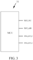
- FIG. 3 is a schematic diagram of a controller according to an implementation of this application.
- FIG. 4 is a schematic diagram of a detection circuit and a switch transistor circuit according to an implementation of this application.
- a controller 31, a detection circuit 32, and a switch transistor circuit 33 are integrated on a circuit board 30.
- the controller, the detection circuit, and the switch transistor circuit are integrated on another circuit board.
- the controller 31 adopts a micro controller unit (MCU). It may be understood that, in another example, the controller 31 may adopt an application-specific integrated chip, or another chip having a processor function.
- the controller 31 has a TEST_VCC port, a TEST_AIN port, a PWM_OUT_P port, and a PWM_OUT_N port.
- the detection circuit 32 includes a resistor R2, an electric heater C2, a resistor R2, a capacitor C2, and a heater 10 connected in series. Specifically, one end of the resistor R2 is electrically connected to the TEST_VCC port of the controller 31, and an other end of the resistor R2 is electrically connected to one end (indicated by WH+ in the figure) of the heater 10. An other end (indicated by WH- in the figure) of the heater 10 is electrically connected to one end of the capacitor C2 and the TEST_AIN port of the controller 31, and an other end of the capacitor C2 is connected to the ground.
- the switch transistor circuit 33 includes a switch transistor Q3, a switch transistor Q5, and a switch transistor Q7.
- the switch transistor Q3 and the switch transistor Q7 are NMOS transistors
- the switch transistor Q5 is a PMOS transistor.
- the PWM_OUT_P port of the controller 31 is electrically connected to a gate of the switch transistor Q3, a drain of the switch transistor Q3 is electrically connected to a gate of the switch transistor Q5, and a source of the switch transistor Q3 is grounded.
- a source of the switch transistor Q5 is electrically connected to the battery core 20 (indicated by VBAT in the figure), and a drain of the switch transistor Q5 is electrically connected to one end (indicated by WH+ in the figure) of the heater 10.
- the PWM_OUT_N port is electrically connected to a gate of the switch transistor Q7, a drain of the switch transistor Q7 is electrically connected to an other end (indicated by WH- in the figure) of the heater 10, and a source of the switch transistor Q7 is grounded.
- the switch transistor circuit 33 is configured to electrically connect the heater 10 to a battery core 20 (indicated by VBAT in the figure) or disconnect the heater from the battery core.
- the controller 31 is configured to: output a control signal to control the switch transistor circuit 33 to be open; control the detection circuit 32 to have the direct current flowing therethrough in a case that the switch transistor circuit 33 is open and after a countdown time of a timer is reached; and determine, based on the duration for which the potential difference between the two ends of the capacitor C2 reaches the preset potential difference threshold, that the aerosol generation article 40 is received in the chamber A or the aerosol generation article 40 is removed from the chamber A, and then control an action of the heater 10.
- the controller 31 is integrated with a countdown timer (not shown in the figure), whereby a function to determine whether the aerosol generation article 40 is received in the chamber A is enabled by using a timed wake-up function, to control the action of the heater 10.
- the heater 10 is controlled to start or stop heating.
- the controller 31 may control the TEST_VCC port to output a high level, so that the detection circuit 32 has the direct current flowing therethrough.
- the heater 10 may be equivalent to a series connection of a resistor R and an inductor L.
- the resistor R is a fixed value
- an inductance of the inductor L is related to receiving of the aerosol generation article 40 in the chamber A, that is, insertion of the aerosol generation article 40 into the chamber A.
- a change in the inductance of the inductor L may affect a magnitude of the line impedance
- the aerosol generation article 40 having the magnetic material may increase the inductance of the inductor L, thereby increasing the line impedance
- a charging time of the capacitor C2 before the aerosol generation article 40 is inserted into the chamber A is different from that after the aerosol generation article 40 is inserted into the chamber A.
- the charging time of the capacitor C2 after the aerosol generation article 40 is inserted into the chamber A is greater than the charging time of the capacitor C2 before the aerosol generation article 40 is inserted into the chamber A.
- the aerosol generation article 40 is received in the chamber A or the aerosol generation article 40 is removed from the chamber A, and then the action of the heater 10 is controlled.
- the TEST_AIN port of controller 31 is an interrupt port, and a countup timer (not shown in the figure) is integrated in the controller 31.
- the controller 31 is configured to: control the countup timer to start countup when controlling the TEST_VCC port to output the high level; generate an interrupt when the potential difference between the two ends of the capacitor C2 reaches the preset potential difference threshold, to obtain a countup time of the countup timer; and determine, based on the countup time of the countup timer, that the aerosol generation article 40 is received in the chamber A or the aerosol generation article 40 is removed from the chamber A, and then control the action of the heater 10.
- the preset potential difference threshold is of a high level, may be a potential difference between the two ends when the capacitor C2 is full, or may be less than the potential difference between the two ends when the capacitor C2 is full.
- the duration for which the potential difference between the two ends of the capacitor C2 reaches the preset potential difference threshold may be compared with a preset time threshold.
- the control signal (such as a square wave signal) is outputted to control the operation of the switch transistor circuit 33, and then the heater 10 is started for heating.
- the switch transistor circuit 33 is controlled to remain open. To be specific, the heater 10 is in an unheated state.
- the preset time threshold may be set to the duration for which the potential difference between the two ends of the capacitor C2 reaches the preset potential difference threshold when the aerosol generation article 40 is not received in the chamber A.
- the heater 10 may be automatically controlled to start heating without a key operation, which improves user experience.
- is very small. Therefore, the duration for which the potential difference between the two ends of the capacitor C2 reaches the preset potential difference threshold is almost unchanged. In this case, the heater 10 is not automatically controlled to start heating, which may play an anti-counterfeiting role.
- a difference between the duration for which the potential difference between the two ends of the capacitor C2 reaches the preset potential difference threshold and the preset time threshold may be determined. If the difference is not greater than the preset difference threshold and is greater than zero, the control signal (such as the square wave signal) is outputted to control the switch transistor circuit 33 to operate, and then the heater 10 is started for heating. If the difference is greater than the preset difference threshold or the difference is less than or equal to zero, the switch transistor circuit 33 is controlled to remain open.
- the control signal such as the square wave signal
- a consistency of the magnetic material may provide fixed time intervals after the aerosol generation article 40 is inserted into the chamber A and before the aerosol generation article 40 is inserted into the chamber A. Therefore, it may be determined, by determining that the difference between the duration for which the potential difference between the two ends of the capacitor C2 reaches the preset potential difference threshold and the preset time threshold is within a preset range, that the aerosol generation article 40 is received in the chamber A.
- the heater 10 is automatically controlled to start heating without a key operation, which improves user experience.
- the heater 10 is not controlled to start heating. Further, if the difference between the duration for which the potential difference between the two ends of the capacitor C2 reaches the preset potential difference threshold and the preset time threshold is less than or equal to zero, it may be determined that the aerosol generation article 40 is not inserted into the chamber A. In this case, the heater 10 is not controlled to start heating.
- the determination of whether the aerosol generation article 40 is received in the chamber A may be performed again in a case that the heater 10 is in a heating gap. If the aerosol generation article 40 is inserted into the chamber A, the heating is continued. If the aerosol generation article 40 is removed from the chamber A, the heating is stopped.
- the determination process reference may be made to the foregoing implementations.
- the heating gap refers to a time period between two adjacent high levels (or low levels) in the square wave signal.
- the controller 31 does not adopt the interrupt.
- the TEST_AIN port is a general port. In this case, when the potential difference between the two ends of the capacitor C2 reaches the preset potential difference threshold, the controller 31 obtains the countup time of the countup timer. The subsequent process is similar to the foregoing process, and details are not described herein.
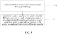
- FIG. 5 is a schematic diagram of a control method for an aerosol generation device according to an implementation of this application.
- the aerosol generation device is consistent with the foregoing content, and details are not described herein.
- the method includes the following steps:
- the method includes:
- the method includes:
- the determining, based on the duration for which the potential difference between the two ends of the capacitor C2 reaches the preset potential difference threshold, that the aerosol generation article 40 is received in the chamber A or the aerosol generation article 40 is removed from the chamber A includes:
- the determining, based on the duration for which the potential difference between the two ends of the capacitor C2 reaches the preset potential difference threshold, that the aerosol generation article 40 is received in the chamber A or the aerosol generation article 40 is removed from the chamber A includes:
- the method includes:
- FIG. 6 is a schematic diagram of a control process of an aerosol generation device according to an implementation of this application.
- Step S21 A switch transistor circuit 33 is open.
- a controller 31 controls a PWM_OUT_P port to output a low level, so that a switch transistor Q3 is turned off, and a switch transistor Q5 is turned off.
- a PWM_OUT_N port is controlled to output the low level, so that a switch transistor Q7 is turned off. In this way, an electrical connection between a heater 10 and a battery core 20 is cut off.
- Step S22 Determine whether a countdown time of a countdown timer is reached.
- a function to determine whether the aerosol generation article 40 is received in the chamber A is enabled by using a timed wake-up function to control the action of the heater 10. If the countdown time of the countdown timer is not reached, the switch transistor circuit 33 is remains open.
- Step S23 Control a countup timer to start countup when a TEST_VCC port is controlled to output a high level.
- Step S24 Whether a TEST_AIN port receives an interrupt signal.
- Step S25 Obtain a countup time of the countup timer.
- Step S26 Determine whether the countup time of the countup timer is greater than a preset time threshold.
- step S27 is performed. Otherwise, it may be determined that the aerosol generation article 40 is not received in the chamber A, and the switch transistor circuit 33 remains open, waiting for timed wake-up.
- Step S27 and Step S28 Determine that the aerosol generation article 40 is received in the chamber A.
- a square wave signal is outputted to control the switch transistor circuit 33, and then the heater 10 is started for heating.
Landscapes
- Containers And Packaging Bodies Having A Special Means To Remove Contents (AREA)
- Control Of Resistance Heating (AREA)
- Nozzles (AREA)
Abstract
Description
- This application claims priority to
Chinese Patent Application No. 202111048301.8, filed with the China National Intellectual Property Administration on September 8, 2021 - This application relates to the field of cigarette devices, and in particular, to an aerosol generation device and a control method therefor.
- During use of smoking articles such as cigarettes or cigars, tobacco is burnt to produce smoke. An attempt has been made to provide substitutes for these tobacco-burning articles by producing products that release compounds without burning. An example of the products is a heat-not-burn product, which releases compounds by heating tobacco rather than burning the tobacco.
- The patent document with the Publication No.
CN111511233A discloses an aerosol generation device and an operation method therefor. An electromagnetic inductor is arranged in a cigarette, and a detector having a coil is arranged in the aerosol generation device. Electromagnetic induction may occur between the coil and the electromagnetic inductor, so that a characteristic change of a current generated by the electromagnetic induction and flowing through the coil may be detected, and an insertion state of the cigarette into the aerosol generation device may be determined. - This application is intended to provide an aerosol generation device and a control method therefor different from an existing cigarette insertion detection method.
- An aspect of this application provides an aerosol generation device, including:
- a chamber, configured to removably receive an aerosol generation article including a magnetic material;
- a heater, configured to heat the aerosol generation article received in the chamber to generate an aerosol;
- a detection circuit, including a capacitor connected in series with the heater; and
- a controller, configured to control the detection circuit to have a direct current flowing therethrough, and determine, based on a duration for which a potential difference between two ends of the capacitor reaches a preset potential difference threshold, that the aerosol generation article is received in the chamber or the aerosol generation article is removed from the chamber. Another aspect of this application provides a control method for an aerosol generation device. The aerosol generation device includes a chamber, a heater, and a detection circuit. The detection circuit includes a capacitor connected in series with the heater. The method includes:
- controlling the detection circuit to have a direct current flowing therethrough; and
- determining, based on the duration for which the potential difference between the two ends of the capacitor reaches the preset potential difference threshold, that the aerosol generation article is received in the chamber or the aerosol generation article is removed from the chamber.
- According to the aerosol generation device and the control method therefor provided in this application, it is determined, based on the duration for which the potential difference between the two ends of the capacitor reaches the preset potential difference threshold, whether a cigarette is inserted into the heating chamber, and then an action of the heater is controlled. The implementation mode is simple, and user experience is improved.
- One or more embodiments are exemplarily described with reference to the corresponding figures in the accompanying drawings, and the descriptions are not to be construed as a limitation on the embodiments. Elements in the accompanying drawings that have same reference numerals are represented as similar elements, and unless otherwise particularly stated, the figures in the accompanying drawings are not drawn to scale.
-
FIG. 1 is a schematic diagram of an aerosol generation device according to an implementation of this application. -
FIG. 2 is a schematic diagram of an aerosol generation article according to an implementation of this application. -
FIG. 3 is a schematic diagram of a controller according to an implementation of this application. -
FIG. 4 is a schematic diagram of a detection circuit and a switch transistor circuit according to an implementation of this application. -
FIG. 5 is a schematic diagram of a control method for an aerosol generation device according to an implementation of this application. -
FIG. 6 is a schematic diagram of a control process of an aerosol generation device according to an implementation of this application. - For ease of understanding of this application, this application is described below in more detail with reference to the accompanying drawings and specific implementations. It should be noted that, when an element is expressed as "being fixed to" another element, the element may be directly on the another element, or one or more intermediate elements may exist between the element and the another element. When one element is expressed as "being connected to" another element, the element may be directly connected to the another element, or one or more intermediate elements may exist between the element and the another element. The terms "upper", "lower", "left", "right", "inner", "outer", and similar expressions used in this specification are merely used for an illustrative purpose.
- Unless otherwise defined, meanings of all technical and scientific terms used in this specification are the same as that usually understood by a person skilled in the technical field to which this application belongs. The terms used in this specification of this application are merely intended to describe objectives of the specific implementations, and are not intended to limit this application. A term "and/or" used in this specification includes any or all combinations of one or more related listed items.
-
FIG. 1 is a schematic diagram of an aerosol generation device according to an implementation of this application. The aerosol generation device includes: - a chamber A, where an
aerosol generation article 40 is removably received in the chamber A; - a
heater 10, where when theaerosol generation article 40 is received in the chamber A, theheater 10 is inserted into theaerosol generation article 40 for heating to generate an aerosol; - a
battery core 20, configured to supply power; and - a
circuit board 30, arranged between thebattery core 20 and theheater 10. Various circuits are integrated on thecircuit board 30 to control the aerosol generation device. For example, thebattery core 20 is controlled to supply power to theheater 10. - The
aerosol generation article 40 is preferably made of a tobacco-containing material that releases a volatile compound from a substrate when being heated, or a non-tobacco material suitable for electric heating to smoke after being heated. Theaerosol generation article 40 is preferably made of a solid substrate, which may include one or more of powder, particles, fragments, strips, or sheets of one or more of vanilla leaves, tobacco leaves, homogeneous tobacco, and expanded tobacco. Alternatively, the solid substrate may include additional tobacco or non-tobacco volatile aroma compounds to be released when the substrate is heated. In some examples, theaerosol generation article 40 includes a liquid substrate, or a carrier carrying the liquid substrate, or a container carrying the liquid substrate. - It should be noted that, heating methods of the
heater 10 include, but are not limited to, resistive heating, electromagnetic heating, and infrared heating. In an exemplary embodiment, a shape of theheater 10 includes, but is not limited to, a needle, a pin, a tube, or a sheet. - It should be further noted that, unlike the example of
FIG. 1 , in another example, it is also feasible that theheater 10 is constructed to heat around at least part of theaerosol generation article 40, commonly referred to as circumferential heating, peripheral heating, or the like. -
FIG. 2 is a schematic diagram of an aerosol generation article according to an implementation of this application. - The
aerosol generation article 40 includes afilter section 41 and anaerosol generation section 42 having an inhalable material. In a preferred implementation, theaerosol generation article 40 is provided with amagnetic material 43. Themagnetic material 43 may be a ferromagnetic material, or another material having a magnetic permeability of approximately 100 H/m or more. Themagnetic material 43 may be a coating formed on an outer surface of theaerosol generation article 40, for example, arranged close to a lower end of the aerosol generation section 202, or may be a component arranged on the outer surface of theaerosol generation article 40. Alternatively, themagnetic material 43 is located in theaerosol generation article 40 and mixed with the inhalable material. -
FIG. 3 is a schematic diagram of a controller according to an implementation of this application.FIG. 4 is a schematic diagram of a detection circuit and a switch transistor circuit according to an implementation of this application. - In this example, a
controller 31, adetection circuit 32, and aswitch transistor circuit 33 are integrated on acircuit board 30. Certainly, it is also feasible that the controller, the detection circuit, and the switch transistor circuit are integrated on another circuit board. Thecontroller 31 adopts a micro controller unit (MCU). It may be understood that, in another example, thecontroller 31 may adopt an application-specific integrated chip, or another chip having a processor function. - In this example, the
controller 31 has a TEST_VCC port, a TEST_AIN port, a PWM_OUT_P port, and a PWM_OUT_N port. - The
detection circuit 32 includes a resistor R2, an electric heater C2, a resistor R2, a capacitor C2, and aheater 10 connected in series. Specifically, one end of the resistor R2 is electrically connected to the TEST_VCC port of thecontroller 31, and an other end of the resistor R2 is electrically connected to one end (indicated by WH+ in the figure) of theheater 10. An other end (indicated by WH- in the figure) of theheater 10 is electrically connected to one end of the capacitor C2 and the TEST_AIN port of thecontroller 31, and an other end of the capacitor C2 is connected to the ground. - The
switch transistor circuit 33 includes a switch transistor Q3, a switch transistor Q5, and a switch transistor Q7. In this example, the switch transistor Q3 and the switch transistor Q7 are NMOS transistors, and the switch transistor Q5 is a PMOS transistor. The PWM_OUT_P port of thecontroller 31 is electrically connected to a gate of the switch transistor Q3, a drain of the switch transistor Q3 is electrically connected to a gate of the switch transistor Q5, and a source of the switch transistor Q3 is grounded. A source of the switch transistor Q5 is electrically connected to the battery core 20 (indicated by VBAT in the figure), and a drain of the switch transistor Q5 is electrically connected to one end (indicated by WH+ in the figure) of theheater 10. The PWM_OUT_N port is electrically connected to a gate of the switch transistor Q7, a drain of the switch transistor Q7 is electrically connected to an other end (indicated by WH- in the figure) of theheater 10, and a source of the switch transistor Q7 is grounded. For other components and the electrical connection thereof, reference may be made toFIG. 3 . Theswitch transistor circuit 33 is configured to electrically connect theheater 10 to a battery core 20 (indicated by VBAT in the figure) or disconnect the heater from the battery core. - In this example, the
controller 31 is configured to: output a control signal to control theswitch transistor circuit 33 to be open; control thedetection circuit 32 to have the direct current flowing therethrough in a case that theswitch transistor circuit 33 is open and after a countdown time of a timer is reached; and determine, based on the duration for which the potential difference between the two ends of the capacitor C2 reaches the preset potential difference threshold, that theaerosol generation article 40 is received in the chamber A or theaerosol generation article 40 is removed from the chamber A, and then control an action of theheater 10. - Specifically, the
controller 31 may control the PWM_OUT_P port to output a low level, so that the switch transistor Q3 is turned off, and the switch transistor Q5 is turned off. In addition, the PWM_OUT_N port is controlled to output the low level, so that the switch transistor Q7 is turned off. In this way, an electrical connection between theheater 10 and thebattery core 20 is cut off. - The
controller 31 is integrated with a countdown timer (not shown in the figure), whereby a function to determine whether theaerosol generation article 40 is received in the chamber A is enabled by using a timed wake-up function, to control the action of theheater 10. To be specific, theheater 10 is controlled to start or stop heating. - The
controller 31 may control the TEST_VCC port to output a high level, so that thedetection circuit 32 has the direct current flowing therethrough. - As shown in
FIG. 4 , theheater 10 may be equivalent to a series connection of a resistor R and an inductor L. The resistor R is a fixed value, and an inductance of the inductor L is related to receiving of theaerosol generation article 40 in the chamber A, that is, insertion of theaerosol generation article 40 into the chamber A. - A line impedance of the
detection circuit 32 may be represented by using the following formula:
- A change in the inductance of the inductor L may affect a magnitude of the line impedance |Z|, and then change a charging time of the capacitor C2. Specifically, when the
aerosol generation article 40 is inserted into the chamber A, theaerosol generation article 40 having the magnetic material may increase the inductance of the inductor L, thereby increasing the line impedance |Z|. - Therefore, after the
controller 31 controls the TEST_VCC port to output the high level, a charging time of the capacitor C2 before theaerosol generation article 40 is inserted into the chamber A is different from that after theaerosol generation article 40 is inserted into the chamber A. The charging time of the capacitor C2 after theaerosol generation article 40 is inserted into the chamber A is greater than the charging time of the capacitor C2 before theaerosol generation article 40 is inserted into the chamber A. - Based on the foregoing principle, it may be determined, based on the duration for which the potential difference between the two ends of the capacitor C2 reaches the preset potential difference threshold, that the
aerosol generation article 40 is received in the chamber A or theaerosol generation article 40 is removed from the chamber A, and then the action of theheater 10 is controlled. - In this example, the TEST_AIN port of
controller 31 is an interrupt port, and a countup timer (not shown in the figure) is integrated in thecontroller 31. - The
controller 31 is configured to: control the countup timer to start countup when controlling the TEST_VCC port to output the high level; generate an interrupt when the potential difference between the two ends of the capacitor C2 reaches the preset potential difference threshold, to obtain a countup time of the countup timer; and determine, based on the countup time of the countup timer, that theaerosol generation article 40 is received in the chamber A or theaerosol generation article 40 is removed from the chamber A, and then control the action of theheater 10. - In this example, the preset potential difference threshold is of a high level, may be a potential difference between the two ends when the capacitor C2 is full, or may be less than the potential difference between the two ends when the capacitor C2 is full.
- In an alternative implementation, the duration for which the potential difference between the two ends of the capacitor C2 reaches the preset potential difference threshold may be compared with a preset time threshold.
- If the duration for which the potential difference between the two ends of the capacitor C2 reaches the preset potential difference threshold is greater than the preset time threshold, it may be determined that the
aerosol generation article 40 is received in the chamber A. In this case, the control signal (such as a square wave signal) is outputted to control the operation of theswitch transistor circuit 33, and then theheater 10 is started for heating. - If the duration for which the potential difference between the two ends of the capacitor C2 reaches the preset potential difference threshold is not greater than the preset time threshold, it may be determined that the
aerosol generation article 40 is not received in the chamber A. In this case, theswitch transistor circuit 33 is controlled to remain open. To be specific, theheater 10 is in an unheated state. - The preset time threshold may be set to the duration for which the potential difference between the two ends of the capacitor C2 reaches the preset potential difference threshold when the
aerosol generation article 40 is not received in the chamber A. - Based on the foregoing determination, when the
aerosol generation article 40 is inserted into the chamber A, theheater 10 may be automatically controlled to start heating without a key operation, which improves user experience. On the other hand, when theaerosol generation article 40 without the magnetic material is inserted into the chamber A, the change of the line impedance |Z| is very small. Therefore, the duration for which the potential difference between the two ends of the capacitor C2 reaches the preset potential difference threshold is almost unchanged. In this case, theheater 10 is not automatically controlled to start heating, which may play an anti-counterfeiting role. - In another alternative implementation, a difference between the duration for which the potential difference between the two ends of the capacitor C2 reaches the preset potential difference threshold and the preset time threshold may be determined. If the difference is not greater than the preset difference threshold and is greater than zero, the control signal (such as the square wave signal) is outputted to control the
switch transistor circuit 33 to operate, and then theheater 10 is started for heating. If the difference is greater than the preset difference threshold or the difference is less than or equal to zero, theswitch transistor circuit 33 is controlled to remain open. - In the implementation, in a case that the
aerosol generation article 40 has a magnetic material, a consistency of the magnetic material may provide fixed time intervals after theaerosol generation article 40 is inserted into the chamber A and before theaerosol generation article 40 is inserted into the chamber A. Therefore, it may be determined, by determining that the difference between the duration for which the potential difference between the two ends of the capacitor C2 reaches the preset potential difference threshold and the preset time threshold is within a preset range, that theaerosol generation article 40 is received in the chamber A. Theheater 10 is automatically controlled to start heating without a key operation, which improves user experience. Otherwise, if the difference between the duration for which the potential difference between the two ends of the capacitor C2 reaches the preset potential difference threshold and the preset time threshold is greater than the preset difference threshold, it may be determined that theaerosol generation article 40 is a counterfeit product. In this case, theheater 10 is not controlled to start heating. Further, if the difference between the duration for which the potential difference between the two ends of the capacitor C2 reaches the preset potential difference threshold and the preset time threshold is less than or equal to zero, it may be determined that theaerosol generation article 40 is not inserted into the chamber A. In this case, theheater 10 is not controlled to start heating. - In the foregoing two implementations, if the
heater 10 has been controlled to start heating, the determination of whether theaerosol generation article 40 is received in the chamber A may be performed again in a case that theheater 10 is in a heating gap. If theaerosol generation article 40 is inserted into the chamber A, the heating is continued. If theaerosol generation article 40 is removed from the chamber A, the heating is stopped. For the determination process, reference may be made to the foregoing implementations. - It should be noted that, in this example, the heating gap refers to a time period between two adjacent high levels (or low levels) in the square wave signal.
- It should be further noted that, unlike the foregoing example, in another example, it is feasible that the
controller 31 does not adopt the interrupt. To be specific, the TEST_AIN port is a general port. In this case, when the potential difference between the two ends of the capacitor C2 reaches the preset potential difference threshold, thecontroller 31 obtains the countup time of the countup timer. The subsequent process is similar to the foregoing process, and details are not described herein. -
FIG. 5 is a schematic diagram of a control method for an aerosol generation device according to an implementation of this application. The aerosol generation device is consistent with the foregoing content, and details are not described herein. - The method includes the following steps:
- Step S11: Control a
detection circuit 32 to have a direct current flowing therethrough. - Step S12: Determine, based on a duration for which a potential difference between two ends of a capacitor C2 reaches a preset potential difference threshold, that an
aerosol generation article 40 is received in a chamber A or theaerosol generation article 40 is removed from the chamber A. - In an example, the method includes:
- controlling a countup timer to start countup when controlling the
detection circuit 32 to have the direct current flowing therethrough; - obtaining a countup time of the countup timer when the potential difference between the two ends of the capacitor C2 reaches the preset potential difference threshold; and
- determining, based on the countup time of the countup timer, that the
aerosol generation article 40 is received in the chamber A or theaerosol generation article 40 is removed from the chamber A. - In an example, the method includes:
- outputting a first control signal to control the
switch transistor circuit 33 to be open; - controlling the
detection circuit 32 to have the direct current flowing therethrough in a case that theswitch transistor circuit 33 is open; and - determining, based on the duration for which the potential difference between the two ends of the capacitor C2 reaches the preset potential difference threshold, that the
aerosol generation article 40 is received in the chamber A or theaerosol generation article 40 is removed from the chamber A. - In an example, the determining, based on the duration for which the potential difference between the two ends of the capacitor C2 reaches the preset potential difference threshold, that the
aerosol generation article 40 is received in the chamber A or theaerosol generation article 40 is removed from the chamber A includes: - comparing the duration for which the potential difference between the two ends of the capacitor C2 reaches the preset potential difference threshold with a preset time threshold;
- outputting a second control signal to control the
switch transistor circuit 33 to operate, and then starting theheater 10 for heating if the duration for which the potential difference between the two ends of the capacitor C2 reaches the preset potential difference threshold is greater than the preset time threshold; and - controlling the
switch transistor circuit 33 to remain open if the duration for which the potential difference between the two ends of the capacitor C2 reaches the preset potential difference threshold is not greater than the preset time threshold. - In an example, the determining, based on the duration for which the potential difference between the two ends of the capacitor C2 reaches the preset potential difference threshold, that the
aerosol generation article 40 is received in the chamber A or theaerosol generation article 40 is removed from the chamber A includes: - determining a difference between the duration for which the potential difference between the two ends of the capacitor C2 reaches the preset potential difference threshold and the preset time threshold;
- outputting a third control signal to control the
switch transistor circuit 33 to operate, and then starting theheater 10 for heating if the difference is not greater than the preset difference threshold and is greater than zero; and - controlling the switch transistor circuit to remain open if the difference is greater than the preset difference threshold.
- In an example, the method includes:
- controlling the
detection circuit 32 to have the direct current flowing therethrough after a countdown time of a countdown timer is reached; and - determining, based on the duration for which the potential difference between the two ends of the capacitor C2 reaches the preset potential difference threshold, that the
aerosol generation article 40 is received in the chamber A or theaerosol generation article 40 is removed from the chamber A. -
FIG. 6 is a schematic diagram of a control process of an aerosol generation device according to an implementation of this application. - Specifically, the control process includes the following steps:
Step S21: Aswitch transistor circuit 33 is open. - A
controller 31 controls a PWM_OUT_P port to output a low level, so that a switch transistor Q3 is turned off, and a switch transistor Q5 is turned off. In addition, a PWM_OUT_N port is controlled to output the low level, so that a switch transistor Q7 is turned off. In this way, an electrical connection between aheater 10 and abattery core 20 is cut off. - Step S22: Determine whether a countdown time of a countdown timer is reached.
- A function to determine whether the
aerosol generation article 40 is received in the chamber A is enabled by using a timed wake-up function to control the action of theheater 10. If the countdown time of the countdown timer is not reached, theswitch transistor circuit 33 is remains open. - Step S23: Control a countup timer to start countup when a TEST_VCC port is controlled to output a high level.
- Step S24: Whether a TEST_AIN port receives an interrupt signal.
- Step S25: Obtain a countup time of the countup timer.
- For example, an interrupt for a high-level signal is generated, and the countup time of the countup timer is read through an interrupt program.
- Step S26: Determine whether the countup time of the countup timer is greater than a preset time threshold.
- If the countup time is greater than the preset time threshold, step S27 is performed. Otherwise, it may be determined that the
aerosol generation article 40 is not received in the chamber A, and theswitch transistor circuit 33 remains open, waiting for timed wake-up. - Step S27 and Step S28: Determine that the
aerosol generation article 40 is received in the chamber A. In this case, a square wave signal is outputted to control theswitch transistor circuit 33, and then theheater 10 is started for heating. - It should be noted that, the specification of this application and the accompanying drawings thereof illustrate preferred embodiments of this application. However, this application may be implemented in various different forms, and is not limited to the embodiments described in this specification. These embodiments are not intended to be an additional limitation on the content of this application, and are described for the purpose of providing a more thorough and comprehensive understanding of the content disclosed in this application. Moreover, the foregoing technical features are further combined to form various embodiments not listed above, and all such embodiments shall be construed as falling within the scope of this application. Further, a person of ordinary skill in the art may make improvements or modifications according to the foregoing descriptions, and all the improvements and modifications shall fall within the protection scope of the appended claims of this application.
Claims (16)
- An aerosol generation device, comprising:a chamber, configured to removably receive an aerosol generation article comprising a magnetic material;a heater, configured to heat the aerosol generation article received in the chamber to generate an aerosol;a detection circuit, comprising a capacitor connected in series with the heater; anda controller, configured to control the detection circuit to have a direct current flowing therethrough, and determine, based on a duration for which a potential difference between two ends of the capacitor reaches a preset potential difference threshold, that the aerosol generation article is received in the chamber or the aerosol generation article is removed from the chamber.
- The aerosol generation device according to claim 1, wherein the detection circuit further comprises resistors connected in series.
- The aerosol generation device according to claim 1, wherein the controller comprises a first port; one end of the detection circuit is electrically connected to the first port, and an other end is electrically connected to the ground; and
the controller is configured to control the first port to output a high level, so that the detection circuit has the direct current flowing therethrough. - The aerosol generation device according to claim 3, wherein the controller comprises a second port; one end of the capacitor is electrically connected to the second port and the heater, and an other end is electrically connected to the ground;the controller further comprises a countup timer; andthe controller is configured to: control the countup timer to start countup when controlling the first port to output the high level; obtain the potential difference between the two ends of the capacitor through the second port; obtain a countup time of the countup timer when the potential difference between the two ends of the capacitor reaches the preset potential difference threshold; and determine, based on the countup time of the countup timer, that the aerosol generation article is received in the chamber or the aerosol generation article is removed from the chamber.
- The aerosol generation device according to claim 3, wherein the controller comprises an interrupt port; one end of the capacitor is electrically connected to the interrupt port and the heater, and an other end is electrically connected to the ground;the controller further comprises a countup timer; andthe controller is configured to: control the countup timer to start countup when controlling the first port to output the high level; generate an interrupt when the potential difference between the two ends of the capacitor reaches the preset potential difference threshold, to obtain a countup time of the countup timer; and determine, based on the countup time of the countup timer, that the aerosol generation article is received in the chamber or the aerosol generation article is removed from the chamber.
- The aerosol generation device according to claim 1, further comprising a switch transistor circuit, whereinthe switch transistor circuit is configured to electrically connect the heater to a battery core or disconnect the heater from the battery core; andthe controller is configured to: output a first control signal to control the switch transistor circuit to be open; control the detection circuit to have the direct current flowing therethrough in a case that the switch transistor circuit is open; and determine, based on the duration for which the potential difference between the two ends of the capacitor reaches the preset potential difference threshold, that the aerosol generation article is received in the chamber or the aerosol generation article is removed from the chamber, and then control the switch transistor circuit.
- The aerosol generation device according to claim 6, wherein the controller is configured to: compare the duration for which the potential difference between the two ends of the capacitor reaches the preset potential difference threshold with a preset time threshold; output a second control signal to control the switch transistor circuit to operate, and then start the heater for heating if the duration for which the potential difference between the two ends of the capacitor reaches the preset potential difference threshold is greater than the preset time threshold; and control the switch transistor circuit to remain open if the duration for which the potential difference between the two ends of the capacitor reaches the preset potential difference threshold is not greater than the preset time threshold.
- The aerosol generation device according to claim 6, wherein the controller is configured to: determine a difference between the duration for which the potential difference between the two ends of the capacitor reaches the preset potential difference threshold and a preset time threshold; output a third control signal to control the switch transistor circuit to operate, and then start the heater for heating if the difference is not greater than the preset difference threshold and is greater than zero; and control the switch transistor circuit to remain open if the difference is greater than the preset difference threshold or less than or equal to zero.
- The aerosol generation device according to claim 7 or 8, wherein the controller is configured to: control the detection circuit to have the direct current flowing therethrough again in a case that the heater is in a heating gap; and determine, based on the duration for which the potential difference between the two ends of the capacitor reaches the preset potential difference threshold, that the aerosol generation article is received in the chamber or the aerosol generation article is removed from the chamber.
- The aerosol generation device according to claim 1, wherein the controller further comprises a countdown timer; and
the controller is configured to: control the detection circuit to have the direct current flowing therethrough after a countdown time of the countdown timer is reached; and determine, based on the duration for which the potential difference between the two ends of the capacitor reaches the preset potential difference threshold, that the aerosol generation article is received in the chamber or the aerosol generation article is removed from the chamber. - A control method for an aerosol generation device, wherein the aerosol generation device comprises a chamber, a heater, and a detection circuit, the detection circuit comprises a capacitor connected in series with the heater, and the method comprises:controlling the detection circuit to have a direct current flowing therethrough; anddetermining, based on the duration for which the potential difference between the two ends of the capacitor reaches the preset potential difference threshold, that the aerosol generation article is received in the chamber or the aerosol generation article is removed from the chamber.
- The method according to claim 11, wherein the aerosol generation device further comprises a countup timer; and
the method comprises:controlling the countup timer to start countup when controlling the detection circuit to have the direct current flowing therethrough;obtaining a countup time of the countup timer when the potential difference between the two ends of the capacitor reaches the preset potential difference threshold; anddetermining, based on the countup time of the countup timer, that the aerosol generation article is received in the chamber or the aerosol generation article is removed from the chamber. - The method according to claim 11, wherein the aerosol generation device further comprises a switch transistor circuit, and
the method comprises:outputting a first control signal to control the switch transistor circuit to be open;controlling the detection circuit to have the direct current flowing therethrough in a case that the switch transistor circuit is open; anddetermining, based on the duration for which the potential difference between the two ends of the capacitor reaches the preset potential difference threshold, that the aerosol generation article is received in the chamber or the aerosol generation article is removed from the chamber, and then controlling the switch transistor circuit. - The method according to claim 13, wherein the determining, based on the duration for which the potential difference between the two ends of the capacitor reaches the preset potential difference threshold, that the aerosol generation article is received in the chamber or the aerosol generation article is removed from the chamber, and then controlling the switch transistor circuit comprises:comparing the duration for which the potential difference between the two ends of the capacitor reaches the preset potential difference threshold with a preset time threshold;outputting a second control signal to control the switch transistor circuit to operate, and then starting the heater for heating if the duration for which the potential difference between the two ends of the capacitor reaches the preset potential difference threshold is greater than the preset time threshold; andcontrolling the switch transistor circuit to remain open if the duration for which the potential difference between the two ends of the capacitor reaches the preset potential difference threshold is not greater than the preset time threshold.
- The method according to claim 13, wherein the determining, based on the duration for which the potential difference between the two ends of the capacitor reaches the preset potential difference threshold, that the aerosol generation article is received in the chamber or the aerosol generation article is removed from the chamber comprises:determining a difference between the duration for which the potential difference between the two ends of the capacitor reaches the preset potential difference threshold and a preset time threshold;outputting a third control signal to control the switch transistor circuit to operate, and then starting the heater for heating if the difference is not greater than the preset difference threshold and is greater than zero; andcontrolling the switch transistor circuit to remain open if the difference is greater than the preset difference threshold.
- The method according to claim 11, wherein the aerosol generation device further comprises a countdown timer; and
the method comprises:controlling the detection circuit to have the direct current flowing therethrough after a countdown time of the countdown timer is reached; anddetermining, based on the duration for which the potential difference between the two ends of the capacitor reaches the preset potential difference threshold, that the aerosol generation article is received in the chamber or the aerosol generation article is removed from the chamber.
Applications Claiming Priority (2)
| Application Number | Priority Date | Filing Date | Title |
|---|---|---|---|
| CN202111048301.8A CN115769914A (en) | 2021-09-08 | 2021-09-08 | Aerosol generating device and control method thereof |
| PCT/CN2022/117905 WO2023036262A1 (en) | 2021-09-08 | 2022-09-08 | Aerosol generation device and control method therefor |
Publications (2)
| Publication Number | Publication Date |
|---|---|
| EP4399982A1 true EP4399982A1 (en) | 2024-07-17 |
| EP4399982A4 EP4399982A4 (en) | 2025-01-22 |
Family
ID=85387941
Family Applications (1)
| Application Number | Title | Priority Date | Filing Date |
|---|---|---|---|
| EP22866723.4A Pending EP4399982A4 (en) | 2021-09-08 | 2022-09-08 | AEROSOL GENERATING DEVICE AND CONTROL METHOD THEREOF |
Country Status (6)
| Country | Link |
|---|---|
| US (1) | US20240349793A1 (en) |
| EP (1) | EP4399982A4 (en) |
| JP (1) | JP7684516B2 (en) |
| KR (1) | KR20240053650A (en) |
| CN (1) | CN115769914A (en) |
| WO (1) | WO2023036262A1 (en) |
Families Citing this family (3)
| Publication number | Priority date | Publication date | Assignee | Title |
|---|---|---|---|---|
| US12520880B2 (en) | 2021-01-18 | 2026-01-13 | Altria Client Services Llc | Heat-not-burn (HNB) aerosol-generating devices including energy based heater control, and methods of controlling a heater |
| CN118511169A (en) | 2021-12-03 | 2024-08-16 | 奥斯米公司 | AI-supported original file management |
| CN118436135A (en) * | 2024-05-31 | 2024-08-06 | 爱奇迹创造有限公司 | Control method of aerosol generating device and aerosol generating device |
Family Cites Families (16)
| Publication number | Priority date | Publication date | Assignee | Title |
|---|---|---|---|---|
| JP4747224B1 (en) * | 2010-07-15 | 2011-08-17 | 株式会社マコメ研究所 | Inductance change detection circuit, displacement detection device, and metal detection device |
| HUE071643T2 (en) * | 2013-12-03 | 2025-09-28 | Philip Morris Products Sa | Aerosol-generating article and electrically operated system incorporating a taggant |
| TWI697289B (en) * | 2014-05-21 | 2020-07-01 | 瑞士商菲利浦莫里斯製品股份有限公司 | Aerosol-forming article, electrically heated aerosol-generating device and system and method of operating said system |
| CN106597063A (en) * | 2017-01-25 | 2017-04-26 | 杭州士兰微电子股份有限公司 | Current detecting circuit and current detecting method |
| CN107144725B (en) * | 2017-05-22 | 2020-09-25 | 钰泰半导体南通有限公司 | Novel method for small current detection |
| KR102231228B1 (en) * | 2017-05-26 | 2021-03-24 | 주식회사 케이티앤지 | Apparatus and method for generating aerosol having cigarette insertion detection function |
| CN107404107B (en) * | 2017-08-15 | 2020-02-14 | 惠州市新泓威科技有限公司 | Dry burning prevention device of electronic cigarette and control method thereof |
| CN108303190B (en) * | 2018-01-08 | 2020-12-22 | 吉士福电子科技(东莞)有限公司 | A device and method for automatically detecting cigarettes |
| KR102267000B1 (en) | 2018-11-23 | 2021-06-18 | 주식회사 케이티앤지 | Aerosol generating apparatus and method for operating the same |
| EP3711531A1 (en) * | 2019-03-22 | 2020-09-23 | Nerudia Limited | Smoking substitute system |
| CN110045808A (en) * | 2019-04-02 | 2019-07-23 | 惠州Tcl移动通信有限公司 | Capacitances to supply power method, system, storage medium and mobile terminal |
| WO2021037403A1 (en) * | 2019-08-23 | 2021-03-04 | Philip Morris Products S.A. | Aerosol-generating device with means for detecting at least one of the insertion or the extraction of an aerosol-generating article into or from the device |
| KR20210088386A (en) * | 2020-01-06 | 2021-07-14 | 주식회사 케이티앤지 | Aerosol generating system |
| KR102397451B1 (en) * | 2020-01-06 | 2022-05-12 | 주식회사 케이티앤지 | Aerosol generating device |
| KR102326985B1 (en) * | 2020-02-05 | 2021-11-16 | 주식회사 케이티앤지 | Aerosol generating device and system |
| KR102328201B1 (en) * | 2020-02-07 | 2021-11-17 | 주식회사 케이티앤지 | Aerosol generating apparatus and method for operating the same |
-
2021
- 2021-09-08 CN CN202111048301.8A patent/CN115769914A/en active Pending
-
2022
- 2022-09-08 EP EP22866723.4A patent/EP4399982A4/en active Pending
- 2022-09-08 KR KR1020247011730A patent/KR20240053650A/en active Pending
- 2022-09-08 WO PCT/CN2022/117905 patent/WO2023036262A1/en not_active Ceased
- 2022-09-08 JP JP2024514464A patent/JP7684516B2/en active Active
- 2022-09-08 US US18/689,449 patent/US20240349793A1/en active Pending
Also Published As
| Publication number | Publication date |
|---|---|
| JP2024533232A (en) | 2024-09-12 |
| WO2023036262A1 (en) | 2023-03-16 |
| KR20240053650A (en) | 2024-04-24 |
| CN115769914A (en) | 2023-03-10 |
| JP7684516B2 (en) | 2025-05-27 |
| US20240349793A1 (en) | 2024-10-24 |
| EP4399982A4 (en) | 2025-01-22 |
Similar Documents
| Publication | Publication Date | Title |
|---|---|---|
| US20240349793A1 (en) | Aerosol generation device and control method therefor | |
| US11937643B2 (en) | Inductive heating circuit for volatilizing smokeable material | |
| JP7390406B2 (en) | Equipment for aerosol generating devices | |
| US20260033547A1 (en) | Aerosol-generating device with means for detecting at least one of the insertion or the extraction of an aerosol-generating article into or from the device | |
| US20250168939A1 (en) | Apparatus for heating smokable material | |
| EP3367830B1 (en) | Article for use with apparatus for heating smokable material | |
| AU2020294182A1 (en) | Temperature determination | |
| CN113068398B (en) | Aerosol generating devices and aerosol generating systems | |
| CN107949285B (en) | Materials for use with devices for heating smokeable materials | |
| CN108348005A (en) | For heating the equipment that can light sucked material | |
| US20230136305A1 (en) | Aerosol generation apparatus and susceptor | |
| US20240016219A1 (en) | Apparatus for an aerosol generating device | |
| CN214386100U (en) | Aerosol generating device and boost circuit thereof | |
| CN208192153U (en) | A kind of electromagnetic heating smoking set that can be evenly heated tobacco particle | |
| US12480786B2 (en) | Distance estimation | |
| WO2024251872A1 (en) | Aerosol provision device | |
| CN120419714A (en) | Aerosol generating system, heating device and control method |
Legal Events
| Date | Code | Title | Description |
|---|---|---|---|
| STAA | Information on the status of an ep patent application or granted ep patent |
Free format text: STATUS: THE INTERNATIONAL PUBLICATION HAS BEEN MADE |
|
| PUAI | Public reference made under article 153(3) epc to a published international application that has entered the european phase |
Free format text: ORIGINAL CODE: 0009012 |
|
| STAA | Information on the status of an ep patent application or granted ep patent |
Free format text: STATUS: REQUEST FOR EXAMINATION WAS MADE |
|
| 17P | Request for examination filed |
Effective date: 20240322 |
|
| AK | Designated contracting states |
Kind code of ref document: A1 Designated state(s): AL AT BE BG CH CY CZ DE DK EE ES FI FR GB GR HR HU IE IS IT LI LT LU LV MC MK MT NL NO PL PT RO RS SE SI SK SM TR |
|
| REG | Reference to a national code |
Ref country code: DE Ref legal event code: R079 Free format text: PREVIOUS MAIN CLASS: A24F0040200000 Ipc: A24F0040530000 |
|
| DAV | Request for validation of the european patent (deleted) | ||
| DAX | Request for extension of the european patent (deleted) | ||
| STAA | Information on the status of an ep patent application or granted ep patent |
Free format text: STATUS: EXAMINATION IS IN PROGRESS |
|
| A4 | Supplementary search report drawn up and despatched |
Effective date: 20241223 |
|
| RIC1 | Information provided on ipc code assigned before grant |
Ipc: A24F 40/20 20200101ALN20241217BHEP Ipc: A24F 40/40 20200101ALI20241217BHEP Ipc: A24F 40/465 20200101ALI20241217BHEP Ipc: A24F 40/53 20200101AFI20241217BHEP |
|
| 17Q | First examination report despatched |
Effective date: 20250110 |