EP4398633A1 - Mobility robustness optimization in wireless communication network - Google Patents
Mobility robustness optimization in wireless communication network Download PDFInfo
- Publication number
- EP4398633A1 EP4398633A1 EP23220753.0A EP23220753A EP4398633A1 EP 4398633 A1 EP4398633 A1 EP 4398633A1 EP 23220753 A EP23220753 A EP 23220753A EP 4398633 A1 EP4398633 A1 EP 4398633A1
- Authority
- EP
- European Patent Office
- Prior art keywords
- network node
- model
- neighboring
- vector
- data vector
- Prior art date
- Legal status (The legal status is an assumption and is not a legal conclusion. Google has not performed a legal analysis and makes no representation as to the accuracy of the status listed.)
- Granted
Links
Images




Classifications
-
- H—ELECTRICITY
- H04—ELECTRIC COMMUNICATION TECHNIQUE
- H04W—WIRELESS COMMUNICATION NETWORKS
- H04W36/00—Hand-off or reselection arrangements
- H04W36/0005—Control or signalling for completing the hand-off
- H04W36/0083—Determination of parameters used for hand-off, e.g. generation or modification of neighbour cell lists
- H04W36/00837—Determination of triggering parameters for hand-off
-
- H—ELECTRICITY
- H04—ELECTRIC COMMUNICATION TECHNIQUE
- H04W—WIRELESS COMMUNICATION NETWORKS
- H04W36/00—Hand-off or reselection arrangements
- H04W36/08—Reselecting an access point
-
- H—ELECTRICITY
- H04—ELECTRIC COMMUNICATION TECHNIQUE
- H04W—WIRELESS COMMUNICATION NETWORKS
- H04W24/00—Supervisory, monitoring or testing arrangements
- H04W24/02—Arrangements for optimising operational condition
-
- H—ELECTRICITY
- H04—ELECTRIC COMMUNICATION TECHNIQUE
- H04W—WIRELESS COMMUNICATION NETWORKS
- H04W36/00—Hand-off or reselection arrangements
- H04W36/0005—Control or signalling for completing the hand-off
- H04W36/0055—Transmission or use of information for re-establishing the radio link
-
- H—ELECTRICITY
- H04—ELECTRIC COMMUNICATION TECHNIQUE
- H04W—WIRELESS COMMUNICATION NETWORKS
- H04W36/00—Hand-off or reselection arrangements
- H04W36/24—Reselection being triggered by specific parameters
- H04W36/249—Reselection being triggered by specific parameters according to timing information
-
- H—ELECTRICITY
- H04—ELECTRIC COMMUNICATION TECHNIQUE
- H04W—WIRELESS COMMUNICATION NETWORKS
- H04W36/00—Hand-off or reselection arrangements
- H04W36/24—Reselection being triggered by specific parameters
- H04W36/30—Reselection being triggered by specific parameters by measured or perceived connection quality data
- H04W36/305—Handover due to radio link failure
Definitions
- Mobility Robustness Optimization is a key use case for User Equipment (UE) mobility and plays a vital role in providing a stable and reliable connection during the UE mobility.
- UE User Equipment
- MRO Mobility Robustness Optimization
- the MRO is primarily aimed at reducing Radio Link Failures (RLFs) and unnecessary HOs (also referred to as Ping-Pong (PP) HOs).
- RLFs Radio Link Failures
- PP Ping-Pong
- UEs may be impacted with the RLFs and the PP HOs, which may lead to poor experience during inter-cell HO. This may be caused by improperly set mobility parameters, such as CIO and TTT parameters.
- the first ML model is configured as a Double Deep Q-Network (DDQN).
- DDQN Double Deep Q-Network
- the network entity is further caused to perform the following operations for each neighboring network node of the at least one neighboring network node.
- the network entity obtains a second data sub-vector by aggregating those numbers (i) and (ii) from the data vector which are interrelated at an inter-node level for a pair of the source network node and the neighboring network node. If a prediction result of the first ML model is that the TTT parameter needs to remain unchanged, the network entity predicts, by using a second ML model, whether a CIO parameter needs to be increased, decreased or remain unchanged.
- the second ML model is configured to use the prediction result of the first ML model and the second data sub-vector as input data.
- CIO parameter change prediction may be triggered in response to the "no change" result predicted for the TTT parameter.
- the network entity may reduce the number of occurrences of one or more types of HO problems (e.g., RLFs and/or PP HOs) in the wireless communication network, thereby improving the overall mobility experience.
- HO problems e.g., RLFs and/or PP HOs
- the at least one type of HO problems comprises at least one of: Too-Late HO, Too-Early Type 1 HO, Too-Early Type 2 HO, and Ping-Pong HO.
- the first ML model is configured as a DDQN.
- the DDQN By using the DDQN, it is possible to increase the efficiency of the TTT parameter change prediction.
- the method further comprises the following steps which are performed each neighboring network node of the at least one neighboring network node.
- a second data sub-vector is obtained by aggregating those numbers (i) and (ii) from the data vector which are interrelated at an inter-node level for a pair of the source network node and the neighboring network node. If a prediction result of the first ML model is that the TTT parameter needs to remain unchanged, a second ML model is used to predict whether a CIO parameter needs to be increased, decreased or remain unchanged.
- the second ML model is configured to use the prediction result of the first ML model and the second data sub-vector as input data.
- CIO parameter change prediction may be triggered in response to the "no change" result predicted for the TTT parameter.
- the network entity may reduce the number of occurrences of one or more types of HO problems (e.g., RLFs and/or PP HOs) in the wireless communication network, thereby improving the overall mobility experience.
- HO problems e.g., RLFs and/or PP HOs
- the second ML model is also configured as a DDQN.
- DDQN By using the DDQN, it is possible to increase the efficiency of the CIO parameter change prediction.
- a network entity in a wireless communication network comprises a means for receiving a data vector comprising: (i) a number of HO attempts made between a source network node and at least one neighboring network node within a time period, and (ii) a number of occurrences of at least one type of HO problems between the source network node and the at least one neighboring network node during the HO attempts.
- the network entity further comprises one or more means for performing the following operations for each neighboring network node of the at least one neighboring network node:
- numerative terminology such as “first”, “second”, etc., may be used herein to describe various embodiments, elements or features, it should be understood that these embodiments, elements or features should not be limited by this numerative terminology. This numerative terminology is used herein only to distinguish one embodiment, element or feature from another embodiment, element or feature. For example, a first ML model discussed below could be called a second ML model, and vice versa, without departing from the teachings of the present disclosure.
- a HO problem may refer to any event which occurs only if a HO procedure (during a HO attempt) cannot be completed in a usual and optimal way (i.e., as defined by 3rd Generation Partnership Project (3GPP) for different communication technologies, such as 4G and 5G).
- 3GPP 3rd Generation Partnership Project
- the TTT parameter is a period of time within which HO criteria must be met, before the HO itself is executed.
- the UE 110 tries to re-establish connection with the source network node 102 (see S2 in FIG. 2 ).
- FIG. 2 schematically shows a TE2 HO event in a wireless communication network 200.
- the network 200 comprises a source network node 202 and two neighboring network nodes 204, 206.
- the source network node 202 serves a source cell 208
- the neighboring network nodes 204, 206 serve neighboring cells 210, 212, respectively.
- a UE 214 e.g., a mobile phone
- a UE 214 is assumed to move in the overlapping area of the cells 208-212, where the UE 214 experiences an HO attempt to the neighboring network node 206 but faces an RLF (see S1 in FIG. 2 ).
- the number of occurrences of each of the undesirable events shown in FIGs. 1-4 may be minimized by properly tuning the CIO and TTT parameters. More specifically, the number of occurrences of each of the TE1, TE2 and PP HO events shown in FIGs. 1 , 2 and 4 , respectively, may be minimized by increasing the TTT parameter and decreasing the CIO parameter. As for the TL HO event shown in FIG. 3 , its number of occurrences may be minimized by decreasing the TTT parameter and increasing the CIO parameter.
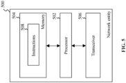
- FIG. 5 shows a block diagram of a network entity 500 in accordance with one example embodiment.
- the network entity 500 is intended to communicate with one or more network nodes (e.g., gNBs) in any of the above-described wireless communication networks.
- the network entity 500 may be implemented as part of a Near-Real Time Radio Intelligent Controller (Near-RT RIC), but the present disclosure is not limited to this implementation example of the network entity 500.
- the network entity 500 comprises a processor 502, a memory 504, and a transceiver 506.
- the memory 504 stores processor-executable instructions 508 which, when executed by the processor 502, cause the processor 502 to perform the aspects of the present disclosure, as will be described below in more detail.
- the memory 504 may be implemented as a classical nonvolatile or volatile memory used in the modern electronic computing machines.
- the nonvolatile memory may include Read-Only Memory (ROM), ferroelectric Random-Access Memory (RAM), Programmable ROM (PROM), Electrically Erasable PROM (EEPROM), solid state drive (SSD), flash memory, magnetic disk storage (such as hard drives and magnetic tapes), optical disc storage (such as CD, DVD and Blu-ray discs), etc.
- ROM Read-Only Memory
- RAM ferroelectric Random-Access Memory
- PROM Programmable ROM
- EEPROM Electrically Erasable PROM
- SSD solid state drive
- flash memory magnetic disk storage (such as hard drives and magnetic tapes), optical disc storage (such as CD, DVD and Blu-ray discs), etc.
- the volatile memory examples thereof include Dynamic RAM, Synchronous DRAM (SDRAM), Double Data Rate SDRAM (DDR SDRAM), Static RAM, etc.
- the method 600 starts with a step S602, in which the processor 502 receives a data vector comprising: (i) a number of HO attempts made between a source network node and at least one neighboring network node within a (last) time period, and (ii) a number of occurrences of at least one type of HO problems between the source network node and the at least one neighboring network node during the HO attempts.
- the types of HO problems may include, but not limited to, TE1 HO, TE2 HO, TL HO, and the PP HO.
- TF _ KPI_RATIO TE1 + TE2 / TE1 + TE2 + TL
- TS_KPI_RATION TL / TE 1 + TE 2 + TL .
- step S602 the method proceeds to steps S604 and S606 performed for each neighboring network node in sequence or in parallel, depending on the performance of the processor 502.
- the processor 502 obtains a first data sub-vector by aggregating those numbers (e.g., those numbers of occurrences of the TE1 HO, TE2 HO, TL HO, PP HO, or any combination thereof) from the data vector which are interrelated at the level of the carrier used by the source network node and the corresponding neighboring network node.
- the numbers from the data vector which are required for the TTT parameter change prediction have to be aggregated for each source cell-carrier pair.
- the processor 502 uses a first ML model to predict whether the TTT parameter needs to be changed (i.e., whether it should be increased, decreased or remain unchanged).
- the first ML model is configured to use the first data sub-vector as input data.
- the method 600 comprises additional steps, in which the processor 502 performs the CIO parameter change prediction for each of the neighboring network nodes. More specifically, the CIO parameter change prediction is performed in response to the "no change" (which is equivalent to "remain unchanged") result predicted for the TTT parameter in the step S606.
- the processor 502 obtains a second data sub-vector by aggregating those numbers (e.g., those numbers of occurrences of the TE1 HO, TE2 HO, TL HO, PP HO, or any combination thereof) from the data vector which are interrelated at an inter-node level for the pair of the source network node and the corresponding neighboring network node.
- the processor 502 uses a second ML model to predict whether the CIO parameter needs to be changed (i.e., whether it should be increased, decreased or remain unchanged).
- the second ML model is configured to use the prediction result of the first ML model and the second data sub-vector as input data.
- the first and second ML models should be pre-trained. Their training may be performed as follows: features for the data vector (i.e., the above-indicated counter values or numbers) may be collected for at least 2 days, whereupon the features may be aggregated as per the optimization cycle duration and correlated along with the CIO and TTT parameters, thereby obtaining the first and second data sub-vectors.
- the first and second ML models may use the corresponding aggregated features of the data vector for the CIO and TTT parameter change prediction (i.e., "decrease”, "increase”, or "no change").
- Each of the first and second ML models may be configured as a Double Deep Q-Network (DDQN) or any other reinforcement learning model.
- DDQN Double Deep Q-Network
- Each of the first and second ML models may be integrated with a custom reward function which, for every parameter change recommendation, analyzes a reward gain obtained based on the number of occurrences of each type of HO problems (e.g., RLFs and PP HO) and drives the model re-training and inference.
- each of the first and second models takes into consideration corresponding one of the first and second data sub-vectors and, based on it, the ML model recommends the best action to be taken for the CIO/TTT parameter (i.e., "decrease”, "increase”, or "no change").
- each of the first and second ML models looks at the above-indicated counter values (e.g., the TE1, TE2, TL and PP values) across subsequent optimization cycles along with the change in the CIO/TTT parameters and learns the pattern in terms of the reward gain obtained across each change.
- the first and second ML models evaluate all the possible outcomes with respect to the predicted reward gain and recommend the CIO and TTT parameter changes for which maximum rewards may be achieved.
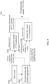
- FIG. 8 schematically explains how a reward may be calculated by comparing data vectors for adjacent periods of time T0 and T1. It should be noted that the data vectors should not necessarily correspond to the adjacent periods of time; in some other embodiments, they may correspond simply to different periods of time.
- W1, W2, W3 are weights assigned to the three hyper-features RLF_RATIO, PP_RATIO, and TF_TS_diff in order to calculate the reward.
- the overall reward is calculated as follows.
- Each of the hyper-features RLF_RATIO, PP_RATIO, and TF_TS_diff obtained at T1 is compared with the respective value at T0.
- the individual feature rewards are calculated, for example, based on the following conditions:
- the threshold value may be set to a small value, such as 0.02.
- the composite reward score is obtained using the feature weights, for example, as follows: W1 ⁇ R1 + W2 ⁇ R2 + W3 ⁇ R3.
- FIG. 9 shows a flowchart of a method 900 for operating the network entity of FIG. 5 in accordance with a second example embodiment.
- the method 900 corresponds to the method 600 supplemented with the second ML model.
- the method 900 starts with a step S902, which is similar to the step S606 of the method 600.
- the processor 502 obtains the first and second data sub-vectors, as discussed above.
- the step S904 corresponds to the combination of the step S604 of the method 600 and the step consisting in obtaining the second data sub-vector.
- the processor 502 may obtain the first and second data sub-vectors in parallel, if required and depending on its performance.
- the method 900 goes to a step S906, which is similar to the step S606 of the method 600. If the first ML model predicts, in the step S906, that no change is required for the TTT parameter of one or more neighboring cells, this prediction result is provided as the additional input data to the second ML model for the CIO parameter change prediction in a next step S908.
- TTT and CIO parameter changes have a similar impact on each type of HO problems (e.g., RLFs and PP HOs), at the source cell-carrier and source cell-neighboring cell levels, respectively.
- the 1st step of prediction involves evaluating the neighboring cell(s) for TTT-based changes, i.e., each source cell-carrier pair with a dominant failure category.
- the second step of prediction is triggered by using the second ML model.
- each of the first and second ML models may be provided to a post-processing component (not shown) in the form of a predicted category, i.e., "increase/decrease/no change" for any of the CIO and TTT parameters.
- a post-processing component not shown
- the complexity lies in applying each predicted change to the relevant parameter.
- the CIO parameter its change predicted by the second ML model may be done for a specific source cell-neighboring cell pair and may be straightaway applied to that particular pair.
- TTT parameter it is set for each source cell-carrier pair and has separate parameters defined for intra/inter frequency neighboring cells, as shown below:
- Parameter Name Abbreviation A3 time to trigger a3TimeToTrigger A3 time to trigger RSRP inter frequency a3Ti meToTrigger Rs r pl n te r F req A3 time to trigger RSRQ inter frequency a3TimeToTriggerRsrqInterFreq
- A5 time to trigger aSTimeTo Trigger A5 time to trigger inter frequency a5TimeToTriggerlnterFreq
- a unique target carrier frequency group is determined, and inferencing is done for each source cell-carrier combination. If there is a change recommended by the first ML model for a particular source cell-carrier pair, the respective TTT parameter applicable for that source cell-carrier pair (intra/inter) is modified as per the predicted category.
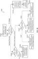
- FIG. 10 shows a flowchart of a method 1000 for updating TTT parameters based on the outcome of the method 600 in accordance with one exemplary embodiment.
- the method 1000 may be executed by the Near-RT RIC.
- the method 1000 starts with a step S1002, in which a particular source cell-carrier pair is selected (in other words, a certain EARFCN is selected).
- the method 1000 proceeds to a step S1004, in which the TTT inference obtained by the using the method 600 or 900 is checked. If it is predicted that the TTT parameter needs to be increased/decreased, the method 1000 goes on to a step S1006, in which it is checked whether an inter-frequency or intra-frequency scenario is under consideration.
- the method 1000 proceeds to a step S1008, in which it is recommended to modify the following parameters: A3timetotrigger and AStimetotrigger. If the intra-frequency scenario takes place, the method 1000 proceeds to a step S1010, in which a type of measurement quality is checked. If the measurement quality is represented by a Reference Signal Received Power (RSRP), then the method goes on to a step S1012, in which it is recommended to modify the following parameters: A3timetotriggerRSRPinter-freq and A5timetotriggerlnterfreq.
- RSRP Reference Signal Received Power
- the method goes on to a step S1014, in which it is recommended to modify the following parameters: A3timetotriggerRSRQinter-freq, A3timetotriggerRSRPinter-freq and A5timetotriggerlnterfreq. If the measurement quality is represented by the RSRQ only, then the method goes on to a step S1016, in which it is recommended to modify the following parameter: A3timetotriggerRSRQinter-freq.
- step S1004 If it is predicted that the TTT parameter needs to remain unchanged, the method 1000 goes on to a step S1018, in which the CIO inference is obtained by using the method 900 (with the two ML models used as shown in FIG. 9 ). In a next step S1020, it is recommended to modify the following parameter: CelllndOffNeigh.
- each step or operation of the methods 600, 900 and 1000, or any combinations of the steps or operations can be implemented by various means, such as hardware, firmware, and/or software.
- one or more of the steps or operations described above can be embodied by processor executable instructions, data structures, program modules, and other suitable data representations.
- the processor-executable instructions which embody the steps or operations described above can be stored on a corresponding data carrier and executed by the processor 502.
- This data carrier can be implemented as any computer-readable storage medium configured to be readable by said at least one processor to execute the processor executable instructions.
- Such computer-readable storage media can include both volatile and nonvolatile media, removable and non-removable media.
- the computer-readable media comprise media implemented in any method or technology suitable for storing information.
- the practical examples of the computer-readable media include, but are not limited to information-delivery media, RAM, ROM, EEPROM, flash memory or other memory technology, CD-ROM, digital versatile discs (DVD), holographic media or other optical disc storage, magnetic tape, magnetic cassettes, magnetic disk storage, and other magnetic storage devices.
Landscapes
- Engineering & Computer Science (AREA)
- Computer Networks & Wireless Communication (AREA)
- Signal Processing (AREA)
- Mobile Radio Communication Systems (AREA)
Abstract
Description
- The present disclosure relates generally to the field of wireless communications, and particularly to a technique for optimizing mobility robustness in a wireless communication network by properly tuning mobility parameters, such as Cell Individual Offset (CIO) and Time-To-Trigger (TTT).
- Mobility Robustness Optimization (MRO) is a key use case for User Equipment (UE) mobility and plays a vital role in providing a stable and reliable connection during the UE mobility. Moreover, since network complexity in 4G and 5G technologies continues to increase, and traffic patterns usually change during the day, there is a need to constantly tune mobility parameters to ensure seamless connectivity experience for UEs.
- The MRO is primarily aimed at reducing Radio Link Failures (RLFs) and unnecessary HOs (also referred to as Ping-Pong (PP) HOs). When moving from one cell to another, UEs may be impacted with the RLFs and the PP HOs, which may lead to poor experience during inter-cell HO. This may be caused by improperly set mobility parameters, such as CIO and TTT parameters.
- Thus, there is a need for a technical solution that would allow the CIO and TTT parameters to be tuned depending on changes in the RLF and PP HO trends which are caused by time-varying traffic patterns.
- This summary is provided to introduce a selection of concepts in a simplified form that are further described below in the detailed description. This summary is not intended to identify key features of the present disclosure, nor is it intended to be used to limit the scope of the present disclosure.
- It is an objective of the present disclosure to provide a technical solution that allows mobility experience to be improved by properly tuning CIO and/or TTT parameters in a wireless communication network.
- The objective above is achieved by the features of the independent claims in the appended claims. Further embodiments and examples are apparent from the dependent claims, the detailed description, and the accompanying drawings.
- According to a first aspect, a network entity in a wireless communication network is provided. The network entity comprises at least one processor and at least one memory. The at least one memory stores instructions that, when executed by the at least one processor, cause the network entity to operate at least as follows. At first, the network entity receives a data vector comprising: (i) a number of HO attempts made between a source network node and at least one neighboring network node within a time period, and (ii) a number of occurrences of at least one type of HO problems between the source network node and the at least one neighboring network node during the HO attempts. Then, the network entity performs the following operations for each neighboring network node of the at least one neighboring network node. The network entity obtains a first data sub-vector by aggregating those numbers (i) and (ii) from the data vector which are interrelated at a level of a carrier used by the source network node and the neighboring network node. Next, the network entity uses a first Machine-Learning (ML) model to predict whether a TTT parameter needs to be increased, decreased or remain unchanged. The first ML model is configured to use the first data sub-vector as input data. By properly tuning the TTT parameter (i.e., deciding whether to increase, decrease or remain it unchanged), the network entity may reduce the number of occurrences of one or more types of HO problems (e.g., RLFs and/or PP HOs) in the wireless communication network, thereby improving the overall mobility experience.
- In one example embodiment of the first aspect, the at least one type of HO problems comprises at least one of: Too-Late HO, Too-
Early Type 1 HO, Too-Early Type 2 HO, and PP HO. By using the number of occurrences of one or more of these types of HO problems in the first ML model, it is possible to provide efficient TTT parameter change prediction. - In one example embodiment of the first aspect, the network entity is further caused to supplement the data vector with at least one of the following values:


Early Type 1 HO between the source network node and each of the at least one neighboring network node, TE2 is the number of occurrences of the Too-Early Type 2 HO between the source network node and each of the at least one neighboring network node, TE = TE1 + TE2, TL is the number of occurrences of the Too-Late HO between the source network node and each of the at least one neighboring network node, PP is the number of occurrences of the PP HO between the source network node and each of the at least one neighboring network node, and HOatt is the number of the HO attempts made between the source network node and each of the at least one neighboring network node. By using these additional values in the first ML model, it is possible to increase the efficiency of the TTT parameter change prediction. - In one example embodiment of the first aspect, the first ML model is configured as a Double Deep Q-Network (DDQN). By using the DDQN, it is possible to increase the efficiency of the TTT parameter change prediction.
- In one example embodiment of the first aspect, the network entity is further caused to perform the following operations for each neighboring network node of the at least one neighboring network node. The network entity obtains a second data sub-vector by aggregating those numbers (i) and (ii) from the data vector which are interrelated at an inter-node level for a pair of the source network node and the neighboring network node. If a prediction result of the first ML model is that the TTT parameter needs to remain unchanged, the network entity predicts, by using a second ML model, whether a CIO parameter needs to be increased, decreased or remain unchanged. The second ML model is configured to use the prediction result of the first ML model and the second data sub-vector as input data. Thus, CIO parameter change prediction may be triggered in response to the "no change" result predicted for the TTT parameter. Similarly, by properly tuning the CIO parameter (i.e., deciding whether to increase, decrease or remain it unchanged), the network entity may reduce the number of occurrences of one or more types of HO problems (e.g., RLFs and/or PP HOs) in the wireless communication network, thereby improving the overall mobility experience.
- In one example embodiment of the first aspect, the second ML model is also configured as a DDQN. By using the DDQN, it is possible to increase the efficiency of the CIO parameter change prediction.
- In one example embodiment of the first aspect, the network entity is further caused to perform the following operations. The network entity receives another data vector comprising: (i) a number of HO attempts made between the source network node and the at least one neighboring network node within another time period, and (ii) a number of occurrences of the at least one type of HO problems between the source network node and the at least one neighboring network node during the HO attempts. Then, the network entity calculates a difference between the numbers (ii) of the data vector and said another data vector. Next, the network entity calculates a reward for the data vector based on whether the difference is more than, less than or equal to a threshold value. After that, the network entity trains at least one of the first ML model and the second ML model by using the reward. By using such a reward in the training phase of the first ML model and the second ML model, it is possible to increase their prediction accuracy.
- According to a second aspect, a method for operating a network entity in a wireless communication network is provided. The method starts with the step of receiving a data vector comprising: (i) a number of HO attempts made between a source network node and at least one neighboring network node within a time period, and (ii) a number of occurrences of at least one type of HO problems between the source network node and the at least one neighboring network node during the HO attempts. Then, the method proceeds to the following steps performed for each neighboring network node of the at least one neighboring network node:
- obtaining a first data sub-vector by aggregating those numbers (i) and (ii) from the data vector which are interrelated at a level of a carrier used by the source network node and the neighboring network node; and
- by using a first ML model, predicting whether a TTT parameter needs to be increased, decreased or remain unchanged, the first ML model being configured to use the first data sub-vector as input data.
- By properly tuning the TTT parameter (i.e., deciding whether to increase, decrease or remain them unchanged), it is possible to reduce the number of occurrences of one or more types of HO problems (e.g., RLFs and/or PP Hos) in the wireless communication network, thereby improving the overall mobility experience.
- In one example embodiment of the second aspect, the at least one type of HO problems comprises at least one of: Too-Late HO, Too-
Early Type 1 HO, Too-Early Type 2 HO, and Ping-Pong HO. By using the number of occurrences of one or more of these types of HO problems in the first ML model, it is possible to provide efficient TTT parameter change prediction. - In one example embodiment of the second aspect, the method further comprises the step of supplementing the data vector with at least one of the following values:


Early Type 1 HO between the source network node and each of the at least one neighboring network node, TE2 is the number of occurrences of the Too-Early Type 2 HO between the source network node and each of the at least one neighboring network node, TE = TE1 + TE2, TL is the number of occurrences of the Too-Late HO between the source network node and each of the at least one neighboring network node, PP is the number of occurrences of the PP HO between the source network node and each of the at least one neighboring network node, and HOatt is the number of the HO attempts made between the source network node and each of the at least one neighboring network node. By using these additional values in the first ML model, it is possible to increase the efficiency of the TTT parameter change prediction. - In one example embodiment of the second aspect, the first ML model is configured as a DDQN. By using the DDQN, it is possible to increase the efficiency of the TTT parameter change prediction.
- In one example embodiment of the second aspect, the method further comprises the following steps which are performed each neighboring network node of the at least one neighboring network node. A second data sub-vector is obtained by aggregating those numbers (i) and (ii) from the data vector which are interrelated at an inter-node level for a pair of the source network node and the neighboring network node. If a prediction result of the first ML model is that the TTT parameter needs to remain unchanged, a second ML model is used to predict whether a CIO parameter needs to be increased, decreased or remain unchanged. The second ML model is configured to use the prediction result of the first ML model and the second data sub-vector as input data. Thus, CIO parameter change prediction may be triggered in response to the "no change" result predicted for the TTT parameter. Similarly, by properly tuning the CIO parameter (i.e., deciding whether to increase, decrease or remain it unchanged), the network entity may reduce the number of occurrences of one or more types of HO problems (e.g., RLFs and/or PP HOs) in the wireless communication network, thereby improving the overall mobility experience.
- In one example embodiment of the second aspect, the second ML model is also configured as a DDQN. By using the DDQN, it is possible to increase the efficiency of the CIO parameter change prediction.
- In one example embodiment of the second aspect, the method further comprises the following steps. Another data vector is received, which comprises: (i) a number of HO attempts made between the source network node and the at least one neighboring network node within another time period, and (ii) a number of occurrences of the at least one type of HO problems between the source network node and the at least one neighboring network node during the HO attempts. Then, a difference between the numbers (ii) of the data vector and said another data vector is calculated. Next, a reward for the data vector is calculated based on whether the difference is more than, less than or equal to a threshold value. After that, at least one of the first ML model and the second ML model is trained by using the reward. By using such a reward in the training phase of the first ML model and the second ML model, it is possible to increase their prediction accuracy.
- According to a third aspect, a computer program product is provided. The computer program product comprises a computer-readable storage medium that stores a computer code. Being executed by at least one processor, the computer code causes the at least one processor to perform the method according to the second aspect. By using such a computer program product, it is possible to simplify the implementation of the method according to the second aspect in any network entity, like the network entity according to the first aspect.
- According to a fourth aspect, a network entity in a wireless communication network is provided. The network entity comprises a means for receiving a data vector comprising: (i) a number of HO attempts made between a source network node and at least one neighboring network node within a time period, and (ii) a number of occurrences of at least one type of HO problems between the source network node and the at least one neighboring network node during the HO attempts. The network entity further comprises one or more means for performing the following operations for each neighboring network node of the at least one neighboring network node:
- obtaining a first data sub-vector by aggregating those numbers (i) and (ii) from the data vector which are interrelated at a level of a carrier used by the source network node and the neighboring network node; and
- by using a first ML model, predicting whether a TTT parameter needs to be increased, decreased or remain unchanged, the first ML model being configured to use the first data sub-vector as input data.
- By properly tuning the TTT parameter (i.e., deciding whether to increase, decrease or remain them unchanged), the network entity may reduce the number of occurrences of one or more types of HO problems (e.g., RLFs and/or PP HOs) in the wireless communication network, thereby improving the overall mobility experience.
- Other features and advantages of the present disclosure will be apparent upon reading the following detailed description and reviewing the accompanying drawings.
- The present disclosure is explained below with reference to the accompanying drawings in which:
-
FIG. 1 schematically shows a Too-Early Type1 Handover (HO) event in a wireless communication network; -
FIG. 2 schematically shows a Too-Early Type2 HO event in a wireless communication network; -
FIG. 3 schematically shows a Too-Late HO event in a wireless communication network; -
FIG. 4 schematically shows a Ping-Pong (PP) HO event in a wireless communication network; -
FIG. 5 shows a block diagram of a network entity in accordance with one example embodiment; -
FIG. 6 shows a flowchart of a method for operating the network entity ofFIG. 5 in accordance with a first example embodiment; -
FIG. 7 shows one possible tabular structure of a data vector used in the method ofFIG. 6 ; -
FIG. 8 schematically explains how a reward may be calculated by comparing data vectors for adjacent periods of time T0 and T1; -
FIG. 9 shows a flowchart of a method for operating the network entity ofFIG. 5 in accordance with a second example embodiment; and -
FIG. 10 shows a flowchart of a method for updating Time-To-Trigger (TTT) parameters based on the outcome of the method ofFIG. 6 . - Various embodiments of the present disclosure are further described in more detail with reference to the accompanying drawings. However, the present disclosure can be embodied in many other forms and should not be construed as limited to any certain structure or function discussed in the following description. In contrast, these embodiments are provided to make the description of the present disclosure detailed and complete.
- According to the detailed description, it will be apparent to the ones skilled in the art that the scope of the present disclosure encompasses any embodiment thereof, which is disclosed herein, irrespective of whether this embodiment is implemented independently or in concert with any other embodiment of the present disclosure. For example, the apparatus and method disclosed herein can be implemented in practice by using any numbers of the embodiments provided herein. Furthermore, it should be understood that any embodiment of the present disclosure can be implemented using one or more of the elements presented in the appended claims.
- Unless otherwise stated, any embodiment recited herein as "example embodiment" should not be construed as preferable or having an advantage over other embodiments.
- Although the numerative terminology, such as "first", "second", etc., may be used herein to describe various embodiments, elements or features, it should be understood that these embodiments, elements or features should not be limited by this numerative terminology. This numerative terminology is used herein only to distinguish one embodiment, element or feature from another embodiment, element or feature. For example, a first ML model discussed below could be called a second ML model, and vice versa, without departing from the teachings of the present disclosure.
- According to the example embodiments disclosed herein, a User Equipment (UE) may refer to an electronic computing device that is configured to perform wireless communications. The UE may be implemented as a mobile station, a mobile terminal, a mobile subscriber unit, a mobile phone, a cellular phone, a smart phone, a cordless phone, a personal digital assistant (PDA), a wireless communication device, a desktop computer, a laptop computer, a tablet computer, a gaming device, a netbook, a smartbook, an ultrabook, a medical mobile device or equipment, a biometric sensor, a wearable device (e.g., a smart watch, smart glasses, a smart wrist band, etc.), an entertainment device (e.g., an audio player, a video player, etc.), a vehicular component or sensor (e.g., a driver-assistance system), a smart meter/sensor, an unmanned vehicle (e.g., an industrial robot, a quadcopter, etc.) and its component (e.g., a self-driving car computer), industrial manufacturing equipment, a global positioning system (GPS) device, an Internet-of-Things (IoT) device, an Industrial loT (IIoT) device, a machine-type communication (MTC) device, a group of Massive loT (MloT) or Massive MTC (mMTC) devices/sensors, or any other suitable mobile device configured to support wireless communications. In some embodiments, the UE may refer to at least two collocated and inter-connected UEs thus defined.
- As used in the example embodiments disclosed herein, a network node may refer to a fixed point of communication/communication node for a UE in a particular wireless communication network. More specifically, the network node may be used to connect the UE to a Data Network (DN) through a Core Network (CN) and may be referred to as a base transceiver station (BTS) in terms of the 2G communication technology, a NodeB in terms of the 3G communication technology, an evolved NodeB (eNodeB or eNB) in terms of the 4G communication technology, and a gNB in terms of the 5G New Radio (NR) communication technology. The network node may serve different cells, such as a macrocell, a microcell, a picocell, a femtocell, and/or other types of cells. The macrocell may cover a relatively large geographic area (e.g., at least several kilometers in radius). The microcell may cover a geographic area less than two kilometers in radius, for example. The picocell may cover a relatively small geographic area, such, for example, as offices, shopping malls, train stations, stock exchanges, etc. The femtocell may cover an even smaller geographic area (e.g., a home). Correspondingly, the network node serving the macrocell may be referred to as a macro node, the network node serving the microcell may be referred to as a micro node, and so on.
- According to the example embodiments disclosed herein, a wireless communication network, in which a UE and a network node communicate with each other, may refer to a cellular or mobile network, a Wireless Local Area Network (WLAN), a Wireless Personal Area Networks (WPAN), a Wireless Wide Area Network (WWAN), a satellite communication (SATCOM) system, or any other type of wireless communication networks. Each of these types of wireless communication networks supports wireless communications according to one or more communication protocol standards. For example, the cellular network may operate according to the Global System for Mobile Communications (GSM) standard, the Code-Division Multiple Access (CDMA) standard, the Wide-Band Code-Division Multiple Access (WCDM) standard, the Time-Division Multiple Access (TDMA) standard, or any other communication protocol standard, the WLAN may operate according to one or more versions of the IEEE 802.11 standards, the WPAN may operate according to the Infrared Data Association (IrDA), Wireless USB, Bluetooth, or ZigBee standard, and the WWAN may operate according to the Worldwide Interoperability for Microwave Access (WiMAX) standard.
- When a UE moves from a source cell to a neighboring cell in a wireless communication network (e.g., 5G network), a source network node (e.g., gNB) serving the source cell may initiate a Handover (HO) for the UE to a neighboring network node (e.g., another gNB) serving the neighboring cell. In other words, the source network node makes a HO attempt in this case. If multiple UEs are about to leave the source cell within a given time period, the source network node will make multiple HO attempts. Not all the multiple HO attempts may be successful; some of them may be failed due to different HO problems. Thus, the number of the HO attempts made by the source network node may be considered as the sum of the number of successful HO attempts and the number of unsuccessful (failed) HO attempts. It should be noted that the ratio of the number of unsuccessful HO attempts to the number of HO attempts is called a HO failure (HOF) ratio.
- In the example embodiments disclosed herein, a HO problem may refer to any event which occurs only if a HO procedure (during a HO attempt) cannot be completed in a usual and optimal way (i.e., as defined by 3rd Generation Partnership Project (3GPP) for different communication technologies, such as 4G and 5G).
- For example, the HO problem may relate to a Radio Link Failure (RLF) that occurs when a radio link connection is lost for a predetermined time duration. RLF events may be categorized into the following 3 types: Too-Late (TL) HO, Too-Early Type1 (TE1) HO, and Too-Early Type2 (TE2) HO. If mobility parameters are set in such a way that a UE does not report HO measurements on time, the UE might lose the connection with a source network node before the HO procedure is initiated. This is what is known as a TL HO event, in which the UE tries to re-establish the connection with another (neighbouring) network node after an RLF detection timer has expired. On the other hand, if the mobility parameters are set to trigger the HO procedure very early, the RLF might occur shortly after HO in a target network node. This is known as a TE1 HO event, in which the UE tries to re-establish the connection with a source network node after the RLF detection timer has expired. Even if the HO procedure is triggered at the right time, an incorrectly defined Cell Individual Offset (CIO) parameter may make the UE handover to a wrong network node, which is followed by an RLF and a reestablishment request to a network node other than the wrong network node or to the source network node. This is known as HO to a wrong cell or TE2 HO.
- The HO problem may also relate to unnecessary HOs (e.g., so-called Ping-Pong (PP) HOs), which do not cause an RLF, but which increase in an unnecessary manner the amount of control data being used for a UE. In other words, in case of PP HOs, the UE is handed over back and forth between two neighboring cells for a short period of time.
-
FIG. 1 schematically shows a TE1 HO event in awireless communication network 100. As shown inFIG. 1 , thenetwork 100 comprises asource network node 102 and a neighboringnetwork node 104. Thesource network node 102 serves asource cell 106, and the neighboringnetwork node 104 serves a neighboringcell 108. A UE 110 (e.g., a mobile phone) is assumed to move to the overlapping area of thecells UE 110 experiences an HO attempt to the neighboringnetwork node 104 but faces an RLF (see S1 inFIG. 1 ). The RLF may be caused, for example, by a too low value of a Time-To-Trigger (TTT) parameter. The TTT parameter is a period of time within which HO criteria must be met, before the HO itself is executed. In response to the RLF, theUE 110 tries to re-establish connection with the source network node 102 (see S2 inFIG. 2 ). -
FIG. 2 schematically shows a TE2 HO event in awireless communication network 200. As shown inFIG. 2 , thenetwork 200 comprises asource network node 202 and twoneighboring network nodes source network node 202 serves asource cell 208, and the neighboringnetwork nodes cells network node 206 but faces an RLF (see S1 inFIG. 2 ). The RLF may be caused, for example, by incorrect selection of the neighboringnetwork node 206 as a target network node due to signal overlap at the cell edge. In response to the RLF, the UE 214 tries to establish connection with the neighboring network node 204 (see S2 inFIG. 2 ). -
FIG. 3 schematically shows a TL HO event in awireless communication network 300. As shown inFIG. 3 , thenetwork 300 comprises asource network node 302 and a neighboringnetwork node 304. Thesource network node 302 serves asource cell 306, and the neighboringnetwork node 304 serves a neighboringcell 308. A UE 310 (e.g., a mobile phone) is assumed to move to the overlapping area of thecells UE 310 faces an RLF, i.e., theUE 310 lost the connection with thesource network node 302 before the HO procedure for the neighboringnetwork node 304 is initiated (see S1 inFIG. 3 ). The RLF may be caused, for example, by a too high value of the TTT parameter. In response to the RLF, theUE 310 tries to re-establish connection with the source network node 304 (see S2 inFIG. 3 ). -
FIG. 4 schematically shows a PP HO event in awireless communication network 400. As shown inFIG. 4 , thenetwork 400 comprises asource network node 402 and a neighboringnetwork node 404. Thesource network node 402 serves asource cell 406, and the neighboringnetwork node 404 serves a neighboringcell 408. A UE 410 (e.g., a mobile phone) is assumed to move in the overlapping area of thecells source network node 402 and the neighboringnetwork node 404 within a short period of time. The PP HOs may occur because of different factors, such as specific UE behavior, radio frequency conditions in the overlapping area, inappropriate network parameterization, etc. - It should be noted that the number of occurrences of each of the undesirable events shown in
FIGs. 1-4 may be minimized by properly tuning the CIO and TTT parameters. More specifically, the number of occurrences of each of the TE1, TE2 and PP HO events shown inFIGs. 1 ,2 and4 , respectively, may be minimized by increasing the TTT parameter and decreasing the CIO parameter. As for the TL HO event shown inFIG. 3 , its number of occurrences may be minimized by decreasing the TTT parameter and increasing the CIO parameter. - The example embodiments disclosed herein provide a technical solution that allows mobility experience to be improved by properly tuning the CIO and/or TTT parameters in a wireless communication network. More specifically, information about a number of HO attempts made between a source network node and each of its neighboring network nodes for a predefined period of time and a number of occurrences of each type of the HO problems (e.g., TE1 HO, TE2 HO, TL HO, PP HO) during the HO attempts are collected as a data vector. Then, for each neighboring network node, a first data sub-vector is obtained by aggregating those numbers from the data vector which are interrelated at a level of a carrier used by the source network node and the neighboring network node, and a second data sub-vector is obtained by aggregating those numbers from the data vector which are interrelated at an inter-node level for a pair of the source network node and the neighboring network node. After that, the first data sub-vector is used by a first Machine-Learning (ML) model to predict whether the TTT parameter needs to be increased, decreased or remain unchanged. If the "no change" result is predicted for the TTT parameter, this causes a second ML model to perform CIO parameter change prediction by using the result of the first ML model and the second data sub-vector as input data.
- It should be noted that the CIO parameter is defined individually for each neighbor relation, which may be represented as a source node/cell-neighboring node/cell pair (i.e., at an inter-node or inter-cell level). As for the TTT parameter, it is a cell level parameter that is defined separately for each target Evolved Universal Terrestrial Radio Access (E-UTRA) Absolute Radio Frequency Channel Number (EARFCN) pertaining to a source cell. For example, if a source network node has (target) neighboring network nodes across 3 carriers, the source network node will have 3 TTT values, one for each target EARFCN. Each unique relation of the source network node or source cell to the target EARFCN may be represented as a source node-carrier or source cell-carrier pair (i.e., at the level of the carrier used by the source and neighboring network nodes). If source and target EARFCNs are the same, an intra-frequency neighbor scenario takes place; if they are different, this relates to an inter-frequency neighbor scenario. Given the above, one can say that the first data sub-vector is obtained by aggregating the data (i.e., numbers) from the data vector for each source cell-neighboring cell pair, while the second data sub-vector is obtained by aggregating the data (i.e., numbers) from the data vector for each source cell-carrier pair.
-
FIG. 5 shows a block diagram of anetwork entity 500 in accordance with one example embodiment. Thenetwork entity 500 is intended to communicate with one or more network nodes (e.g., gNBs) in any of the above-described wireless communication networks. Thenetwork entity 500 may be implemented as part of a Near-Real Time Radio Intelligent Controller (Near-RT RIC), but the present disclosure is not limited to this implementation example of thenetwork entity 500. As shown inFIG. 5 , thenetwork entity 500 comprises aprocessor 502, amemory 504, and atransceiver 506. Thememory 504 stores processor-executable instructions 508 which, when executed by theprocessor 502, cause theprocessor 502 to perform the aspects of the present disclosure, as will be described below in more detail. It should be noted that the number, arrangement, and interconnection of the constructive elements constituting thenetwork entity 500, which are shown inFIG. 5 , are not intended to be any limitation of the present disclosure, but merely used to provide a general idea of how the constructive elements may be implemented within thenetwork entity 500. For example, theprocessor 502 may be replaced with several processors, as well as thememory 504 may be replaced with several removable and/or fixed storage devices, depending on particular applications. Furthermore, in some embodiments, thetransceiver 506 may be implemented as two individual devices, with one for a receiving operation and another for a transmitting operation. Irrespective of its implementation, thetransceiver 506 is intended to be capable of performing different operations required to perform the data reception and transmission, such, for example, as signal modulation/demodulation, encoding/decoding, etc. In other embodiments, thetransceiver 506 may be part of theprocessor 502 itself. - The
processor 502 may be implemented as a CPU, general-purpose processor, single-purpose processor, microcontroller, microprocessor, application specific integrated circuit (ASIC), field programmable gate array (FPGA), digital signal processor (DSP), complex programmable logic device, etc. It should be also noted that theprocessor 502 may be implemented as any combination of one or more of the aforesaid. As an example, theprocessor 502 may be a combination of two or more microprocessors. - The
memory 504 may be implemented as a classical nonvolatile or volatile memory used in the modern electronic computing machines. As an example, the nonvolatile memory may include Read-Only Memory (ROM), ferroelectric Random-Access Memory (RAM), Programmable ROM (PROM), Electrically Erasable PROM (EEPROM), solid state drive (SSD), flash memory, magnetic disk storage (such as hard drives and magnetic tapes), optical disc storage (such as CD, DVD and Blu-ray discs), etc. As for the volatile memory, examples thereof include Dynamic RAM, Synchronous DRAM (SDRAM), Double Data Rate SDRAM (DDR SDRAM), Static RAM, etc. - The processor-
executable instructions 508 stored in thememory 504 may be configured as a computer-executable program code which causes theprocessor 502 to perform the aspects of the present disclosure. The computer-executable program code for carrying out operations or steps for the aspects of the present disclosure may be written in any combination of one or more programming languages, such as Java, C++, or the like. In some examples, the computer-executable program code may be in the form of a high-level language or in a pre-compiled form and be generated by an interpreter (also pre-stored in the memory 504) on the fly. -
FIG. 6 shows a flowchart of amethod 600 for operating thenetwork entity 500 in accordance with a first example embodiment. - The
method 600 starts with a step S602, in which theprocessor 502 receives a data vector comprising: (i) a number of HO attempts made between a source network node and at least one neighboring network node within a (last) time period, and (ii) a number of occurrences of at least one type of HO problems between the source network node and the at least one neighboring network node during the HO attempts. As noted earlier, the types of HO problems may include, but not limited to, TE1 HO, TE2 HO, TL HO, and the PP HO. Each network node may be equipped with HO problem type-specific counters and may periodically (every "n" duration, where n is the optimization cycle period) report the counter values to thenetwork entity 500, so that theprocessor 502 may trace changes in the trend of each type of HO problems by comparing the current data vector with the past data vector, as will be explained below in detail. - In some embodiments, the
processor 502 may supplement, in or after the step S602, the data vector with one or more of the following values (hyper-features):


-
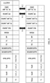
FIG. 7 shows one possible tabular structure of the data vector used in themethod 600. As shown inFIG. 7 , in addition to the features TE1, TE2, TL, PP and HOatt, the data vector received at time instant T0 may also comprise the above-indicated hyper-features RLF_RATIO, TF_TS_diff (in modulus) and PP_RATIO, as well as a source cell ID (i.e., Cell_A), a target neighboring cell ID (i.e., Cell_B), a duplex scheme (i.e., Frequency-Division Duplexing (FDD)/Time-Division Duplexing (TDD)), a source cell EARFCN, a target neighboring cell EARFCN, TF_KPI_RATIO (i.e., the ratio of the number of occurrences of TE1 HO and TE2 HO to the total number of RLFs), and TS_KPI_RATIO (i.e., the ratio of the number of occurrences of TL HO to the total number of RLFs). The last two hyper-features are defined as follows:

- The last column ("CIO/TTT") in the tabular structure of the data vector in
FIG. 7 is intended for the result of CIO/TTT parameter change prediction (i.e., "increase", "decrease", "no change"). It should be noted that the CIO parameter change prediction is triggered when the "no change" result is predicted for the TTT parameter, as will be discussed below in more detail. - After the step S602, the method proceeds to steps S604 and S606 performed for each neighboring network node in sequence or in parallel, depending on the performance of the
processor 502. - In the step S604, the
processor 502 obtains a first data sub-vector by aggregating those numbers (e.g., those numbers of occurrences of the TE1 HO, TE2 HO, TL HO, PP HO, or any combination thereof) from the data vector which are interrelated at the level of the carrier used by the source network node and the corresponding neighboring network node. In other words, the numbers from the data vector which are required for the TTT parameter change prediction have to be aggregated for each source cell-carrier pair. - Next, in the step S606, the
processor 502 uses a first ML model to predict whether the TTT parameter needs to be changed (i.e., whether it should be increased, decreased or remain unchanged). The first ML model is configured to use the first data sub-vector as input data. - In one embodiment, the
method 600 comprises additional steps, in which theprocessor 502 performs the CIO parameter change prediction for each of the neighboring network nodes. More specifically, the CIO parameter change prediction is performed in response to the "no change" (which is equivalent to "remain unchanged") result predicted for the TTT parameter in the step S606. For this purpose, theprocessor 502 obtains a second data sub-vector by aggregating those numbers (e.g., those numbers of occurrences of the TE1 HO, TE2 HO, TL HO, PP HO, or any combination thereof) from the data vector which are interrelated at an inter-node level for the pair of the source network node and the corresponding neighboring network node. In other words, the numbers from the data vector which are required for CIO parameter change prediction have to be aggregated for each source cell-target cell (neighbor relation) pair. After that, theprocessor 502 uses a second ML model to predict whether the CIO parameter needs to be changed (i.e., whether it should be increased, decreased or remain unchanged). The second ML model is configured to use the prediction result of the first ML model and the second data sub-vector as input data. - The first and second ML models should be pre-trained. Their training may be performed as follows: features for the data vector (i.e., the above-indicated counter values or numbers) may be collected for at least 2 days, whereupon the features may be aggregated as per the optimization cycle duration and correlated along with the CIO and TTT parameters, thereby obtaining the first and second data sub-vectors. The first and second ML models may use the corresponding aggregated features of the data vector for the CIO and TTT parameter change prediction (i.e., "decrease", "increase", or "no change"). Each of the first and second ML models may be configured as a Double Deep Q-Network (DDQN) or any other reinforcement learning model. Each of the first and second ML models may be integrated with a custom reward function which, for every parameter change recommendation, analyzes a reward gain obtained based on the number of occurrences of each type of HO problems (e.g., RLFs and PP HO) and drives the model re-training and inference. In the inference mode, each of the first and second models takes into consideration corresponding one of the first and second data sub-vectors and, based on it, the ML model recommends the best action to be taken for the CIO/TTT parameter (i.e., "decrease", "increase", or "no change"). From model re-training perspective, each of the first and second ML models looks at the above-indicated counter values (e.g., the TE1, TE2, TL and PP values) across subsequent optimization cycles along with the change in the CIO/TTT parameters and learns the pattern in terms of the reward gain obtained across each change. Thus, for the first and second data sub-vectors, the first and second ML models evaluate all the possible outcomes with respect to the predicted reward gain and recommend the CIO and TTT parameter changes for which maximum rewards may be achieved.
-
FIG. 8 schematically explains how a reward may be calculated by comparing data vectors for adjacent periods of time T0 and T1. It should be noted that the data vectors should not necessarily correspond to the adjacent periods of time; in some other embodiments, they may correspond simply to different periods of time. InFIG. 8 , W1, W2, W3 are weights assigned to the three hyper-features RLF_RATIO, PP_RATIO, and TF_TS_diff in order to calculate the reward. Based on the comparison of the two data vectors, the overall reward is calculated as follows. Each of the hyper-features RLF_RATIO, PP_RATIO, and TF_TS_diff obtained at T1 is compared with the respective value at T0. The individual feature rewards are calculated, for example, based on the following conditions: - Condition 1: If T1 value < (T0 value + threshold), assign a positive reward (R1), e.g., +2;
- Condition 2: If T1 value "is within" (T0 value +/- threshold), assign a positive reward (R2), e.g., +1;
- Condition 3: If T1 value > (T0 value + threshold), assign a negative reward (R3), e.g., -2;
- The threshold value may be set to a small value, such as 0.02.
- The above conditions are checked for all the 3 hypo-features and based on the individual feature rewards, the composite reward score is obtained using the feature weights, for example, as follows: W1·R1 + W2·R2 + W3·R3.
-
FIG. 9 shows a flowchart of amethod 900 for operating the network entity ofFIG. 5 in accordance with a second example embodiment. In general, themethod 900 corresponds to themethod 600 supplemented with the second ML model. Themethod 900 starts with a step S902, which is similar to the step S606 of themethod 600. In a next step S904, theprocessor 502 obtains the first and second data sub-vectors, as discussed above. In other words, the step S904 corresponds to the combination of the step S604 of themethod 600 and the step consisting in obtaining the second data sub-vector. Theprocessor 502 may obtain the first and second data sub-vectors in parallel, if required and depending on its performance. After the step S904, themethod 900 goes to a step S906, which is similar to the step S606 of themethod 600. If the first ML model predicts, in the step S906, that no change is required for the TTT parameter of one or more neighboring cells, this prediction result is provided as the additional input data to the second ML model for the CIO parameter change prediction in a next step S908. In general, TTT and CIO parameter changes have a similar impact on each type of HO problems (e.g., RLFs and PP HOs), at the source cell-carrier and source cell-neighboring cell levels, respectively. Adequately, the 1st step of prediction involves evaluating the neighboring cell(s) for TTT-based changes, i.e., each source cell-carrier pair with a dominant failure category. For specific cell-carrier pairs with a mixed failure category scenario, for which the first ML model does not recommend any TTT optimization, the second step of prediction is triggered by using the second ML model. - As also follows from
FIG. 9 , the inference of each of the first and second ML models may be provided to a post-processing component (not shown) in the form of a predicted category, i.e., "increase/decrease/no change" for any of the CIO and TTT parameters. Now, the complexity lies in applying each predicted change to the relevant parameter. As for the CIO parameter, its change predicted by the second ML model may be done for a specific source cell-neighboring cell pair and may be straightaway applied to that particular pair. As for the TTT parameter, it is set for each source cell-carrier pair and has separate parameters defined for intra/inter frequency neighboring cells, as shown below:Parameter Name Abbreviation A3 time to trigger a3TimeToTrigger A3 time to trigger RSRP inter frequency a3Ti meToTrigger Rs r pl n te r F req A3 time to trigger RSRQ inter frequency a3TimeToTriggerRsrqInterFreq A5 time to trigger aSTimeTo Trigger A5 time to trigger inter frequency a5TimeToTriggerlnterFreq RSRQ A5 inter-frequency time to trigger a5TimeToTriggerRsrqInterFreq - In order to set the TTT parameter value, for each corresponding source cell, a unique target carrier frequency group is determined, and inferencing is done for each source cell-carrier combination. If there is a change recommended by the first ML model for a particular source cell-carrier pair, the respective TTT parameter applicable for that source cell-carrier pair (intra/inter) is modified as per the predicted category.
-
FIG. 10 shows a flowchart of amethod 1000 for updating TTT parameters based on the outcome of themethod 600 in accordance with one exemplary embodiment. Similar to themethods method 1000 may be executed by the Near-RT RIC. Themethod 1000 starts with a step S1002, in which a particular source cell-carrier pair is selected (in other words, a certain EARFCN is selected). Next, themethod 1000 proceeds to a step S1004, in which the TTT inference obtained by the using themethod method 1000 goes on to a step S1006, in which it is checked whether an inter-frequency or intra-frequency scenario is under consideration. If the inter-frequency scenario takes place, themethod 1000 proceeds to a step S1008, in which it is recommended to modify the following parameters: A3timetotrigger and AStimetotrigger. If the intra-frequency scenario takes place, themethod 1000 proceeds to a step S1010, in which a type of measurement quality is checked. If the measurement quality is represented by a Reference Signal Received Power (RSRP), then the method goes on to a step S1012, in which it is recommended to modify the following parameters: A3timetotriggerRSRPinter-freq and A5timetotriggerlnterfreq. If the measurement quality is represented by the RSRP and a Reference Signal Received Quality (RSRQ), then the method goes on to a step S1014, in which it is recommended to modify the following parameters: A3timetotriggerRSRQinter-freq, A3timetotriggerRSRPinter-freq and A5timetotriggerlnterfreq. If the measurement quality is represented by the RSRQ only, then the method goes on to a step S1016, in which it is recommended to modify the following parameter: A3timetotriggerRSRQinter-freq. Referring back to the step S1004, If it is predicted that the TTT parameter needs to remain unchanged, themethod 1000 goes on to a step S1018, in which the CIO inference is obtained by using the method 900 (with the two ML models used as shown inFIG. 9 ). In a next step S1020, it is recommended to modify the following parameter: CelllndOffNeigh. - It should be noted that each step or operation of the
methods processor 502. This data carrier can be implemented as any computer-readable storage medium configured to be readable by said at least one processor to execute the processor executable instructions. Such computer-readable storage media can include both volatile and nonvolatile media, removable and non-removable media. By way of example, and not limitation, the computer-readable media comprise media implemented in any method or technology suitable for storing information. In more detail, the practical examples of the computer-readable media include, but are not limited to information-delivery media, RAM, ROM, EEPROM, flash memory or other memory technology, CD-ROM, digital versatile discs (DVD), holographic media or other optical disc storage, magnetic tape, magnetic cassettes, magnetic disk storage, and other magnetic storage devices. - Although the example embodiments of the present disclosure are described herein, it should be noted that any various changes and modifications could be made in the embodiments of the present disclosure, without departing from the scope of legal protection which is defined by the appended claims. In the appended claims, the word "comprising" does not exclude other elements or operations, and the indefinite article "a" or "an" does not exclude a plurality. The mere fact that certain measures are recited in mutually different dependent claims does not indicate that a combination of these measures cannot be used to advantage.
Claims (15)
- A network entity in a wireless communication network, comprising means for:receiving a data vector comprising: (i) a number of Handover (HO) attempts made between a source network node and at least one neighboring network node within a time period, and (ii) a number of occurrences of at least one type of HO problems between the source network node and the at least one neighboring network node during the HO attempts;for each of the at least one neighboring network node:obtaining a first data sub-vector by aggregating those numbers (i) and (ii) from the data vector which are interrelated at a level of a carrier used by the source network node and the neighboring network node; andby using a first Machine-Learning (ML) model, predicting whether a Time-To-Trigger (TTT) parameter needs to be increased, decreased or remain unchanged, the first ML model being configured to use the first data sub-vector as input data.
- The network entity of claim 1, wherein the at least one type of HO problems comprises at least one of:Too-Late HO;Too-Early Type 1 HO;Too-Early Type 2 HO; andPing-Pong (PP) HO.
- The network entity of claim 2, wherein the means are configured to supplement the data vector with at least one of the following values:


 TE1 is a number of occurrences of the Too-Early Type 1 HO between the source network node and each of the at least one neighboring network node,TE2 is a number of occurrences of the Too-Early Type 2 HO between the source network node and each of the at least one neighboring network node,
 TL is a number of occurrences of the Too-Late HO between the source network node and each of the at least one neighboring network node,PP is a number of occurrences of the PP HO between the source network node and each of the at least one neighboring network node, andHOatt is a number of the HO attempts made between the source network node and each of the at least one neighboring network node.
 - The network entity of any of claims 1 to 3, wherein the ML model is configured as a Double Deep Q-Network (DDQN).
- The network entity of any of claims 1 to 4, wherein the means are configured to:
for each of the at least one neighboring network node:obtain a second data sub-vector by aggregating those numbers (i) and (ii) from the data vector which are interrelated at an inter-node level for a pair of the source network node and the neighboring network node; andif a prediction result of the first ML model is that the TTT parameter needs to remain unchanged, predict, by using a second ML model, whether a Cell Individual Offset (CIO) parameter needs to be increased, decreased or remain unchanged, the second ML model being configured to use the prediction result of the first ML model and the second data sub-vector as input data. - The network entity of claim 5, wherein the second ML model is configured as a DDQN.
- The network entity of any of claims 1 to 4, wherein the means are configured to:receive another data vector comprising: (i) a number of HO attempts made between the source network node and the at least one neighboring network node within another time period, and (ii) a number of occurrences of the at least one type of HO problems between the source network node and the at least one neighboring network node during the HO attempts;calculate a difference between the numbers (ii) of the data vector and said another data vector;calculate a reward for the data vector based on whether the difference is more than, less than or equal to a threshold value; andtrain the first ML model by using the reward.
- The network entity of claim 5 or 6, wherein the means are configured to:receive another data vector comprising: (i) a number of HO attempts made between the source network node and the at least one neighboring network node within another time period, and (ii) a number of occurrences of the at least one type of HO problems between the source network node and the at least one neighboring network node during the HO attempts;calculate a difference between the numbers (ii) of the data vector and said another data vector;calculate a reward for the data vector based on whether the difference is more than, less than or equal to a threshold value; andtrain each of the first ML model and the second ML model by using the reward.
- A method for operating a network entity in a wireless communication network, comprising:receiving a data vector comprising: (i) a number of Handover (HO) attempts made between a source network node and at least one neighboring network node within a time period, and (ii) a number of occurrences of at least one type of HO problems between the source network node and the at least one neighboring network node during the HO attempts;for each of the at least one neighboring network node:obtaining a first data sub-vector by aggregating those numbers (i) and (ii) from the data vector which are interrelated at a level of a carrier used by the source network node and the neighboring network node; andby using a first Machine-Learning (ML) model, predicting whether a Time-To-Trigger (TTT) parameter needs to be increased, decreased or remain unchanged, the first ML model being configured to use the first data sub-vector as input data.
- The method of claim 9, wherein the at least one type of HO problems comprises at least one of:Too-Late HO;Too-Early Type 1 HO;Too-Early Type 2 HO; andPing-Pong (PP) HO.
- The method of claim 10, further comprising supplementing the data vector with at least one of the following values:


 TE1 is a number of occurrences of the Too-Early Type 1 HO between the source network node and each of the at least one neighboring network node,TE2 is a number of occurrences of the Too-Early Type 2 HO between the source network node and each of the at least one neighboring network node,
 TL is a number of occurrences of the Too-Late HO between the source network node and each of the at least one neighboring network node,PP is a number of occurrences of the PP HO between the source network node and each of the at least one neighboring network node, andHOatt is a number of the HO attempts made between the source network node and each of the at least one neighboring network node.
 - The method of any of claims 9 to 11, further comprising, for each of the at least one neighboring network node:obtaining a second data sub-vector by aggregating those numbers (i) and (ii) from the data vector which are interrelated at an inter-node level for a pair of the source network node and the neighboring network node; andif a prediction result of the first ML model is that the TTT parameter needs to remain unchanged, predicting, by using a second ML model, whether a Cell Individual Offset (CIO) parameter needs to be increased, decreased or remain unchanged, the second ML model being configured to use the prediction result of the first ML model and the second data sub-vector as input data.
- The method of any of claims 9 to 11, further comprising:receiving another data vector comprising: (i) a number of HO attempts made between the source network node and the at least one neighboring network node within another time period, and (ii) a number of occurrences of the at least one type of HO problems between the source network node and the at least one neighboring network node during the HO attempts;calculating a difference between the numbers (ii) of the data vector and said another data vector;calculating a reward for the data vector based on whether the difference is more than, less than or equal to a threshold value; andtraining the first ML model by using the reward.
- The method of claim 12, further comprising:receiving another data vector comprising: (i) a number of HO attempts made between the source network node and the at least one neighboring network node within another time period, and (ii) a number of occurrences of the at least one type of HO problems between the source network node and the at least one neighboring network node during the HO attempts;calculating a difference between the numbers (ii) of the data vector and said another data vector;calculating a reward for the data vector based on whether the difference is more than, less than or equal to a threshold value; andtraining each of the first ML model and the second ML model by using the reward.
- A computer program product comprising a computer-readable storage medium, wherein the computer-readable storage medium stores a computer code which, when executed by at least one processor, causes the at least one processor to perform the method according to at least one of claims 9 to 14.
Applications Claiming Priority (1)
| Application Number | Priority Date | Filing Date | Title |
|---|---|---|---|
| FI20235013 | 2023-01-04 |
Publications (2)
| Publication Number | Publication Date |
|---|---|
| EP4398633A1 true EP4398633A1 (en) | 2024-07-10 |
| EP4398633B1 EP4398633B1 (en) | 2026-03-18 |
Family
ID=89428688
Family Applications (1)
| Application Number | Title | Priority Date | Filing Date |
|---|---|---|---|
| EP23220753.0A Active EP4398633B1 (en) | 2023-01-04 | 2023-12-29 | Mobility robustness optimization in wireless communication network |
Country Status (3)
| Country | Link |
|---|---|
| US (1) | US12063529B2 (en) |
| EP (1) | EP4398633B1 (en) |
| CN (1) | CN118301691B (en) |
Citations (2)
| Publication number | Priority date | Publication date | Assignee | Title |
|---|---|---|---|---|
| WO2022058013A1 (en) * | 2020-09-17 | 2022-03-24 | Telefonaktiebolaget Lm Ericsson (Publ) | Methods and apparatuses for handover procedures |
| WO2022258196A1 (en) * | 2021-06-11 | 2022-12-15 | Nokia Technologies Oy | Determine handover parameters by machine learning |
Family Cites Families (9)
| Publication number | Priority date | Publication date | Assignee | Title |
|---|---|---|---|---|
| US6944144B2 (en) * | 2003-02-28 | 2005-09-13 | Microsoft Corporation | Vertical roaming in wireless networks through improved quality of service measures |
| WO2013020584A1 (en) * | 2011-08-09 | 2013-02-14 | Nokia Siemens Networks Oy | Mobility robustness optimization with an extended key performance indicator message |
| JP6256334B2 (en) | 2012-06-29 | 2018-01-10 | 日本電気株式会社 | Handover optimization system, handover optimization control device, and handover parameter adjustment device |
| CN103501504B (en) * | 2013-09-12 | 2016-06-08 | 西安交通大学 | A kind of mobile robustness optimization method based on switching statistics of easy realization |
| US10484892B2 (en) * | 2018-02-20 | 2019-11-19 | Verizon Patent And Licensing Inc. | Contextualized network optimization |
| FI20205232A1 (en) * | 2020-03-04 | 2021-09-05 | Nokia Solutions & Networks Oy | Machine learning-based optimization of handover parameters |
| US12001932B2 (en) | 2020-07-27 | 2024-06-04 | Intel Corporation | Hierarchical reinforcement learning algorithm for NFV server power management |
| EP4197219B1 (en) | 2020-08-11 | 2024-12-04 | Nokia Technologies Oy | Path-aware cognitive handover optimization |
| US11109283B1 (en) * | 2020-09-22 | 2021-08-31 | Accenture Global Solutions Limited | Handover success rate prediction and management using machine learning for 5G networks |
-
2023
- 2023-12-29 EP EP23220753.0A patent/EP4398633B1/en active Active
-
2024
- 2024-01-03 CN CN202410010456.XA patent/CN118301691B/en active Active
- 2024-01-04 US US18/404,080 patent/US12063529B2/en active Active
Patent Citations (2)
| Publication number | Priority date | Publication date | Assignee | Title |
|---|---|---|---|---|
| WO2022058013A1 (en) * | 2020-09-17 | 2022-03-24 | Telefonaktiebolaget Lm Ericsson (Publ) | Methods and apparatuses for handover procedures |
| WO2022258196A1 (en) * | 2021-06-11 | 2022-12-15 | Nokia Technologies Oy | Determine handover parameters by machine learning |
Non-Patent Citations (1)
| Title |
|---|
| MAVENIR INCORPORATED: "Beam Management Enhancement using AI/ML", vol. RAN WG1, no. e-Meeting; 20220509 - 20220520, 29 April 2022 (2022-04-29), XP052203876, Retrieved from the Internet <URL:https://ftp.3gpp.org/tsg_ran/WG1_RL1/TSGR1_109-e/Docs/R1-2204938.zip R1-2204938 Beam Management Enhancement by AIML.docx> [retrieved on 20220429] * |
Also Published As
| Publication number | Publication date |
|---|---|
| EP4398633B1 (en) | 2026-03-18 |
| US20240224078A1 (en) | 2024-07-04 |
| US12063529B2 (en) | 2024-08-13 |
| CN118301691A (en) | 2024-07-05 |
| CN118301691B (en) | 2025-04-01 |
Similar Documents
| Publication | Publication Date | Title |
|---|---|---|
| EP2826300B1 (en) | Mobility parameter adjustment and mobility state estimation in heterogeneous networks | |
| CN109495935B (en) | A handover method, base station and user terminal | |
| CN116034599A (en) | Method, UE and network node for failure prediction | |
| CN112335278B (en) | Method, apparatus and computer-readable medium for network optimization | |
| Awada et al. | A SON-based algorithm for the optimization of inter-RAT handover parameters | |
| EP3148246B1 (en) | Measurement device and method, and control device and method for wireless network | |
| Park et al. | LTE mobility enhancements for evolution into 5G | |
| JP2023076771A (en) | Setting information transmission/reception method, device, and communication system | |
| Pjanić et al. | Early-scheduled handover preparation in 5g nr millimeter-wave systems | |
| US20260031921A1 (en) | Method, apparatus and computer program | |
| EP4398633B1 (en) | Mobility robustness optimization in wireless communication network | |
| WO2023111150A1 (en) | Machine-learning agent parameter initialization in wireless communication network | |
| US20250211309A1 (en) | Data collection method for beam management based on machine learning and wireless communication device | |
| WO2025172748A1 (en) | Network- or ue-controlled resumption of radio resource management measurements in measurement windows | |
| US12593236B2 (en) | Intelligent adaptive measurement gaps for low mobility user equipment (UEs) | |
| CN120075913A (en) | Communication method and device | |
| WO2025172750A1 (en) | Network- or ue-controlled resumption of radio resource management measurements in measurement windows | |
| WO2025172751A1 (en) | Network- or ue-controlled resumption of radio resource management measurements in measurement windows | |
| EP3145235B1 (en) | Wireless base station, communication system, wireless-parameter optimization method, and storage medium | |
| US12574280B2 (en) | Iterative initialization of machine-learning agent parameters in wireless communication network | |
| WO2025184807A1 (en) | Configuration method, terminal device, and network device | |
| WO2026102137A1 (en) | Enabling artificial intelligence techniques for measurement prediction and reporting | |
| Saha et al. | Machine Learning based Mobility Robustness Optimization For Next Generation Cellular Network | |
| WO2024052429A1 (en) | Rrm mobility handling based on beam management reports | |
| WO2025016524A1 (en) | Reduced cell measurement and reporting for wireless networks |
Legal Events
| Date | Code | Title | Description |
|---|---|---|---|
| PUAI | Public reference made under article 153(3) epc to a published international application that has entered the european phase |
Free format text: ORIGINAL CODE: 0009012 |
|
| STAA | Information on the status of an ep patent application or granted ep patent |
Free format text: STATUS: THE APPLICATION HAS BEEN PUBLISHED |
|
| AK | Designated contracting states |
Kind code of ref document: A1 Designated state(s): AL AT BE BG CH CY CZ DE DK EE ES FI FR GB GR HR HU IE IS IT LI LT LU LV MC ME MK MT NL NO PL PT RO RS SE SI SK SM TR |
|
| STAA | Information on the status of an ep patent application or granted ep patent |
Free format text: STATUS: REQUEST FOR EXAMINATION WAS MADE |
|
| 17P | Request for examination filed |
Effective date: 20250107 |
|
| GRAP | Despatch of communication of intention to grant a patent |
Free format text: ORIGINAL CODE: EPIDOSNIGR1 |
|
| STAA | Information on the status of an ep patent application or granted ep patent |
Free format text: STATUS: GRANT OF PATENT IS INTENDED |
|
| INTG | Intention to grant announced |
Effective date: 20250704 |
|
| GRAJ | Information related to disapproval of communication of intention to grant by the applicant or resumption of examination proceedings by the epo deleted |
Free format text: ORIGINAL CODE: EPIDOSDIGR1 |
|
| STAA | Information on the status of an ep patent application or granted ep patent |
Free format text: STATUS: REQUEST FOR EXAMINATION WAS MADE |
|
| GRAP | Despatch of communication of intention to grant a patent |
Free format text: ORIGINAL CODE: EPIDOSNIGR1 |
|
| STAA | Information on the status of an ep patent application or granted ep patent |
Free format text: STATUS: GRANT OF PATENT IS INTENDED |
|
| INTC | Intention to grant announced (deleted) | ||
| INTG | Intention to grant announced |
Effective date: 20251007 |
|
| GRAS | Grant fee paid |
Free format text: ORIGINAL CODE: EPIDOSNIGR3 |
|
| GRAA | (expected) grant |
Free format text: ORIGINAL CODE: 0009210 |
|
| STAA | Information on the status of an ep patent application or granted ep patent |
Free format text: STATUS: THE PATENT HAS BEEN GRANTED |
|
| AK | Designated contracting states |
Kind code of ref document: B1 Designated state(s): AL AT BE BG CH CY CZ DE DK EE ES FI FR GB GR HR HU IE IS IT LI LT LU LV MC ME MK MT NL NO PL PT RO RS SE SI SK SM TR |
|
| REG | Reference to a national code |
Ref country code: CH Ref legal event code: F10 Free format text: ST27 STATUS EVENT CODE: U-0-0-F10-F00 (AS PROVIDED BY THE NATIONAL OFFICE) Effective date: 20260318 Ref country code: GB Ref legal event code: FG4D |
|
| REG | Reference to a national code |
Ref country code: DE Ref legal event code: R096 Ref document number: 602023013682 Country of ref document: DE |
|
| REG | Reference to a national code |
Ref country code: IE Ref legal event code: FG4D |