EP4398600A1 - Ultrasonic transducer and ultrasonic inspection system - Google Patents
Ultrasonic transducer and ultrasonic inspection system Download PDFInfo
- Publication number
- EP4398600A1 EP4398600A1 EP22864694.9A EP22864694A EP4398600A1 EP 4398600 A1 EP4398600 A1 EP 4398600A1 EP 22864694 A EP22864694 A EP 22864694A EP 4398600 A1 EP4398600 A1 EP 4398600A1
- Authority
- EP
- European Patent Office
- Prior art keywords
- input
- piezoelectric element
- output
- ultrasonic
- detection signals
- Prior art date
- Legal status (The legal status is an assumption and is not a legal conclusion. Google has not performed a legal analysis and makes no representation as to the accuracy of the status listed.)
- Pending
Links
Images




Classifications
-
- G—PHYSICS
- G01—MEASURING; TESTING
- G01N—INVESTIGATING OR ANALYSING MATERIALS BY DETERMINING THEIR CHEMICAL OR PHYSICAL PROPERTIES
- G01N29/00—Investigating or analysing materials by the use of ultrasonic, sonic or infrasonic waves; Visualisation of the interior of objects by transmitting ultrasonic or sonic waves through the object
- G01N29/22—Details, e.g. general constructional or apparatus details
-
- B—PERFORMING OPERATIONS; TRANSPORTING
- B06—GENERATING OR TRANSMITTING MECHANICAL VIBRATIONS IN GENERAL
- B06B—METHODS OR APPARATUS FOR GENERATING OR TRANSMITTING MECHANICAL VIBRATIONS OF INFRASONIC, SONIC, OR ULTRASONIC FREQUENCY, e.g. FOR PERFORMING MECHANICAL WORK IN GENERAL
- B06B1/00—Methods or apparatus for generating mechanical vibrations of infrasonic, sonic, or ultrasonic frequency
- B06B1/02—Methods or apparatus for generating mechanical vibrations of infrasonic, sonic, or ultrasonic frequency making use of electrical energy
- B06B1/0207—Driving circuits
-
- G—PHYSICS
- G01—MEASURING; TESTING
- G01N—INVESTIGATING OR ANALYSING MATERIALS BY DETERMINING THEIR CHEMICAL OR PHYSICAL PROPERTIES
- G01N29/00—Investigating or analysing materials by the use of ultrasonic, sonic or infrasonic waves; Visualisation of the interior of objects by transmitting ultrasonic or sonic waves through the object
- G01N29/04—Analysing solids
- G01N29/043—Analysing solids in the interior, e.g. by shear waves
-
- G—PHYSICS
- G01—MEASURING; TESTING
- G01N—INVESTIGATING OR ANALYSING MATERIALS BY DETERMINING THEIR CHEMICAL OR PHYSICAL PROPERTIES
- G01N29/00—Investigating or analysing materials by the use of ultrasonic, sonic or infrasonic waves; Visualisation of the interior of objects by transmitting ultrasonic or sonic waves through the object
- G01N29/22—Details, e.g. general constructional or apparatus details
- G01N29/24—Probes
- G01N29/2437—Piezoelectric probes
-
- G—PHYSICS
- G01—MEASURING; TESTING
- G01S—RADIO DIRECTION-FINDING; RADIO NAVIGATION; DETERMINING DISTANCE OR VELOCITY BY USE OF RADIO WAVES; LOCATING OR PRESENCE-DETECTING BY USE OF THE REFLECTION OR RERADIATION OF RADIO WAVES; ANALOGOUS ARRANGEMENTS USING OTHER WAVES
- G01S15/00—Systems using the reflection or reradiation of acoustic waves, e.g. sonar systems
- G01S15/02—Systems using the reflection or reradiation of acoustic waves, e.g. sonar systems using reflection of acoustic waves
- G01S15/06—Systems determining the position data of a target
- G01S15/08—Systems for measuring distance only
- G01S15/10—Systems for measuring distance only using transmission of interrupted, pulse-modulated waves
-
- G—PHYSICS
- G01—MEASURING; TESTING
- G01S—RADIO DIRECTION-FINDING; RADIO NAVIGATION; DETERMINING DISTANCE OR VELOCITY BY USE OF RADIO WAVES; LOCATING OR PRESENCE-DETECTING BY USE OF THE REFLECTION OR RERADIATION OF RADIO WAVES; ANALOGOUS ARRANGEMENTS USING OTHER WAVES
- G01S15/00—Systems using the reflection or reradiation of acoustic waves, e.g. sonar systems
- G01S15/02—Systems using the reflection or reradiation of acoustic waves, e.g. sonar systems using reflection of acoustic waves
- G01S15/06—Systems determining the position data of a target
- G01S15/42—Simultaneous measurement of distance and other co-ordinates
-
- G—PHYSICS
- G01—MEASURING; TESTING
- G01S—RADIO DIRECTION-FINDING; RADIO NAVIGATION; DETERMINING DISTANCE OR VELOCITY BY USE OF RADIO WAVES; LOCATING OR PRESENCE-DETECTING BY USE OF THE REFLECTION OR RERADIATION OF RADIO WAVES; ANALOGOUS ARRANGEMENTS USING OTHER WAVES
- G01S7/00—Details of systems according to groups G01S13/00, G01S15/00, G01S17/00
- G01S7/52—Details of systems according to groups G01S13/00, G01S15/00, G01S17/00 of systems according to group G01S15/00
- G01S7/523—Details of pulse systems
- G01S7/524—Transmitters
-
- G—PHYSICS
- G01—MEASURING; TESTING
- G01S—RADIO DIRECTION-FINDING; RADIO NAVIGATION; DETERMINING DISTANCE OR VELOCITY BY USE OF RADIO WAVES; LOCATING OR PRESENCE-DETECTING BY USE OF THE REFLECTION OR RERADIATION OF RADIO WAVES; ANALOGOUS ARRANGEMENTS USING OTHER WAVES
- G01S7/00—Details of systems according to groups G01S13/00, G01S15/00, G01S17/00
- G01S7/52—Details of systems according to groups G01S13/00, G01S15/00, G01S17/00 of systems according to group G01S15/00
- G01S7/523—Details of pulse systems
- G01S7/526—Receivers
Definitions
- the present invention relates to an ultrasonic transducer and an ultrasonic inspection system, in particular to an ultrasonic transducer and an ultrasonic inspection system including a piezoelectric element.
- Ultrasonic transducers including piezoelectric elements are known in the art. Such an ultrasonic transducer is disclosed in Japanese Patent Publication No. JP 6259584 , for example.
- the ultrasonic transducer disclosed in the above Japanese Patent Publication No. JP 6259584 includes a piezoelectric element.
- the piezoelectric element is configured to produce ultrasonic waves, and to receive waves reflected from an object to be inspected (inspection target) and outputs the waves.
- the ultrasonic transducer disclosed in the above Japanese Patent Publication No. JP 6259584 includes an inductor and two resistor elements.
- a constant-resistance circuit is composed of the piezoelectric element, the inductor, and the two resistor elements.
- insertion loss corresponding to two processes which are the input and the output, occurs in the inductor and the two resistor elements, which compose the constant-resistance circuit.
- the insertion loss corresponding to two processes reduces intensity of detection signals output from the ultrasonic transducer. For this reason, it is desired to suppress the reduction of the intensity of the detection signals even in a case in which such a constant-resistance circuit is provided for impedance matching.
- the present invention is intended to solve the above problem, and one object of the present invention is to provide an ultrasonic transducer and an ultrasonic inspection system capable of suppressing reduction of intensity of detection signals even in a case in which a constant-resistance circuit is provided for impedance matching.
- the ultrasonic transducer according to the first aspect is configured to produce the ultrasonic waves in response to the input waves that are input from the ultrasonic transceiver through the input transmission path to the piezoelectric element through the parallel circuit.
- the ultrasonic transducer is configured to output the detection signals from the piezoelectric element to the ultrasonic transceiver through an output transmission path that is different from the input transmission path without passing the detection signals through the parallel circuit. Accordingly, the input waves can be input to the piezoelectric element through the parallel circuit, which is included in the constant-resistance circuit for impedance matching, while the detection signals can be output without passing through the parallel circuit, which includes the resistor element and the inductor.
- the detection signals from the piezoelectric element can be output without passing through the parallel circuit, which is included in the constant-resistance circuit, by cutting off the detection signals that pass through the constant-resistance circuit by using the cut-off circuit, and as a result it is possible to easily suppress the reduction of the intensity of the detection signals that are output from the piezoelectric element.
- the cutoff circuit includes a pair of diodes connected in parallel to each other with polarities of the diodes being opposite to each other; and that forward voltages of the pair of diodes are substantially equal to each other in magnitude.
- the detection signals when a voltage greater than the forward voltage is applied, the detection signals can pass through the cut-off circuit, while when a voltage smaller than the forward voltage is applied, the detection signals can be cut off by the cutoff circuit irrespective of a polarity of the voltage.
- the pair of diodes pass the input waves that have a voltage value greater than the forward voltage to the piezoelectric element, and can cut off the detection signals that have a voltage value smaller than the forward voltage.
- the constant-resistance circuit can be constructed of the resistor element and the inductor of the parallel circuit, the piezoelectric element, and the termination resistor of the output transmission path in transmission of ultrasonic waves (in the input of the detection signals), while the detection signals can be output through the output transmission path terminated by the termination resistor without passing through the parallel circuit, which includes the resistor element and the inductor, in reception of ultrasonic waves (in the output of the detection signals).
- the resistor and the inductor of the parallel circuit, the piezoelectric element, and the termination resistor of the output transmission path can be used for impedance matching both in the input and the output of the detection signals. Consequently, the reduction of the intensity of the detection signals can be suppressed by outputting the detection signals without passing the detection signals through the parallel circuit while performing impedance matching both in the input and the output of the detection signals.
- the input waves can be input to the piezoelectric element through each of the parallel circuits, which are included in the constant-resistance circuits for impedance matching, while the detection signals from each of the plurality of piezoelectric elements can be output without passing through the parallel circuit, which includes the resistor element and the inductor. Consequently, a wide area of the inspection target can be collectively inspected by the plurality of piezoelectric elements provided, and the reduction of the intensity of the detection signals output from each of the plurality of piezoelectric elements can be suppressed.
- an ultrasonic inspection system 100 and an ultrasonic transducer 101 according to a first embodiment with reference to FIGS. 1 to 4 .
- an inspection target P is inspected by emitting ultrasonic waves toward the inspection target P and detecting the waves that are reflected from the inspection target P.
- the ultrasonic inspection system 100 is used for ultrasonic diagnosis, non-destructive ultrasonic inspection, etc., for example.
- the pulser receiver 102 is configured to output (transmit) input waves (transmission pulses) to the ultrasonic transducer 101 through the cable 103. Also, the pulser receiver 102 is configured to acquire (receive) detection signals (reception pulses) from the ultrasonic transducer 101 through the cable 104.
- the pulser receiver 102 includes a transceiver circuit (not shown) including an amplifier, etc., and can amplify the detection signals and output the amplified detection signals to the analyzer 105.
- the analyzer 105 is configured to generate a test result of the inspection target P by analyzing the detection signals from the pulser receiver 102.
- the analyzer 105 is a personal computer (PC) used by inspection operators who inspect the inspection target.
- the cable 103 is a transmission path through which input waves are input from the pulser receiver 102 to the ultrasonic transducer 101.
- the cable 104 is a transmission path that is provided separately from the cable 103 and configured to output (receive) the detection signal from the ultrasonic transducer 101.
- the cable 103 and the cable 104 are coaxial cables.
- a characteristic impedance of the cable 103 is substantially equal to a characteristic impedance of the cable 104 in magnitude.
- the cable 103 and the cable 104 have a characteristic impedance of approximately 50 [ ⁇ ].
- the resistance value of the resistor element 21 of the parallel circuit 20 and the resistance value of the termination resistor 40 are substantially equal to the characteristic impedance of the cable 103 (approximately 50 ⁇ ).
- a product Zc ⁇ Zl of an impedance Zc of the piezoelectric element 10 and an impedance Zl of the inductor 22 of the parallel circuit 20 is substantially equal to the square of the characteristic impedance of the cable 103.
- the detection signals from the piezoelectric element 10 can be output so as to output the detection signals only through the cable 104 (output transmission path) without influence of the parallel circuit 20, which is included in the constant-resistance circuit, by a simple configuration of the pair of diodes 31 and 32 without using a structure for switching between passage and cutoff statuses of the cutoff circuit 30 such as a switching circuit, it is possible to more easily suppress the reduction of the intensity of the detection signals that are output from the piezoelectric element 10.
- the pulser receiver 202 is configured to output (transmit) input waves (transmission pulses) to the ultrasonic transducer 201 through the cable 203, and to acquire (receive) detection signals (reception pulses) from the ultrasonic transducer 201 through the cable 204 similar to the pulser receiver 102 in the first embodiment.
- the pulser receiver 202 is configured to output the amplified detection signals to the analyzer 105.
- the cut-off circuit 30 in the transmission of ultrasonic waves (in the input of the detection signals), can be considered as a conductor similar to the first embodiment.
- the cable 204 is terminated by the termination resistor 240. Accordingly, a circuit equivalent to the circuit in FIG. 6 in the transmission of the ultrasonic waves can be represented by a circuit diagram shown in FIG. 7 .
- the pulser receiver 302 includes termination resistors 340 (termination resistors 340a, 340b, 340c, ... , 340x) for impedance matching for the cables 304a, 304b, 304c, ... , 304x in the cable 304 set.
- Each of the termination resistors 340 has a resistance value (approximately 50 [ ⁇ ]) substantially equal to the characteristic impedance of each of the cables 304 similar to the termination resistor 40 in the first embodiment.
- Each of the plurality of capacitors 360 is connected in parallel to corresponding one of the plurality of piezoelectric elements 310.
- an impedance of the piezoelectric element 310 is likely to be high. For this reason, an influence of electromagnetic noises from the surroundings on the detection signals output from the piezoelectric element 310 will be large.
- the impedance can be adjusted to a small value by connecting the capacitor 360 in parallel to the piezoelectric element 310.
- a capacitance of each capacitor 360 is designed based on a capacitance of piezoelectric element 310, a characteristic impedance of the cable 304 on the output side, and a frequency of the input waves.
- a capacitance of the capacitor 360x is designed so that a combined capacitance C x of the piezoelectric element 310x and the capacitor 360x is expressed by the following equation (1).
- C x 1 / Z 304 ⁇ u
- Z 304 is the characteristic impedance of the cable 304.
- the angular frequency ⁇ u is represented by 2 ⁇ f u .
- the ultrasonic transducer 301 is designed so that a product of a combined impedance of each piezoelectric element 310 and each capacitor 360, and the impedance of each inductor 322 is a square of the characteristic impedance of each cable 303 (a product of a resistance of each resistor element 21 and a resistance of each termination resistor 340).
- the ultrasonic inspection system 300 is configured to individually input the input waves to each piezoelectric element 310 of the ultrasonic transducer 301 through each cable 303 while impedance matching for each cable 303 is performed.
- the detection signals are cut off by each cutoff circuit 330 so that a part provided on the input side with respect to the cut-off circuit 330 is electrically separated.
- the ultrasonic inspection system 300 is configured to output the detection signals from each piezoelectric element 310 of the ultrasonic transducer 301 to the pulser receiver 302 without passing the detection signals through the parallel circuit 320 while impedance matching for each cable 304 is performed by each termination resistor 340.
- the other configuration of the third embodiment is similar to the configuration of the first embodiment.
- a plurality of piezoelectric elements 310 are provided; a plurality of parallel circuits 320 are provided so that the plurality of parallel circuits are connected to input sides of the plurality of piezoelectric elements 310 one by one; and the ultrasonic transducer is configured to produce the ultrasonic waves in response to the input waves that are input from the pulser receiver 302 (ultrasonic transceiver) through each of the cables 303 (each of a plurality of input transmission paths) that correspond to the plurality of piezoelectric elements 310 to corresponding one of the plurality of piezoelectric elements 310 through each of the plurality of parallel circuits 320, and to output the detection signals from the corresponding one of the plurality of piezoelectric elements 310 to the pulser receiver 302 through each of a plurality of cables 304 (output transmission paths) that correspond to the plurality of piezoelectric elements 310 without passing the detection signals through corresponding one of the plurality of parallel circuits 320.
- the input waves can be input to the piezoelectric element 310 through each of the parallel circuits 320, which are included in the constant-resistance circuits for impedance matching, while the detection signals from each of the plurality of piezoelectric elements 310 can be output without passing through the parallel circuit 320, which includes the resistor element 21 and the inductor 322. Consequently, a wide area of the inspection target P can be collectively inspected by the plurality of piezoelectric elements 310 provided, and the reduction of the intensity of the detection signals output from each of the plurality of piezoelectric elements 310 can be suppressed.
- a plurality of capacitors 360 each of which is connected in parallel to corresponding one of the plurality of piezoelectric elements 310 are provided. Accordingly, even in a case in which areas of the plurality of piezoelectric elements 310 are small so that their impedances are relatively large, each combined impedance can be reduced by each capacitor 360 connected in parallel to each piezoelectric element 310, and as a result it is possible to reduce influences of electromagnetic noises from the surroundings on the detection signals output from the piezoelectric elements 310.
- the other advantages of the third embodiment are similar to the first and second embodiments.
- an input transmission path and an output transmission path can be included in a single cable.
- a single cable can include two signal lines as the input transmission path and the output transmission path.
- the cables 303 (a plurality of transmission input paths) and the cables 304 (a plurality of output transmission paths) are separate cables.
- signal lines that are the plurality of input transmission paths, and signal lines that are the plurality of output transmission paths can be collectively included in a single cable.
- the piezoelectric element 10 has a structure including a piezoelectric piece (piezoelectric material) of a polymeric material
- the present invention is not limited to this.
- the piezoelectric piece of the piezoelectric element can be formed of a ceramic material.
- the cut-off circuit 30 is constructed of the pair of diodes 31 and 32
- the present invention is not limited to this.
- the cut-off circuit can be constructed of a solid-state relay, a semiconductor switch using gallium arsenide, a high-speed high-voltage semiconductor switch, etc.
- a control signal is additionally provided to switch between connection statuses of a status in transmission of ultrasonic waves (in input of detection signals) and a status in reception of ultrasonic waves (in output of the detection signals) so as to switch between passage and cut-off statuses of the cut-off circuit.
- the ultrasonic transducer 301 is a linear array transducer including a plurality of piezoelectric elements 310 aligned in a straight line
- the ultrasonic transducer can be a multi-array transducer including a plurality of piezoelectric elements arranged in a grid shape (in a plane).
- the ultrasonic transducer 301 includes a plurality of capacitors 360 each of which is connected in parallel to corresponding one of the plurality of piezoelectric elements 310
- the present invention is not limited to this.
- the plurality of piezoelectric elements no capacitors that are connected in parallel to the piezoelectric elements can be provided.
- the capacitor can be connected in parallel to the piezoelectric element.
- the present invention is not limited to this.
- the plurality of piezoelectric elements 310 can have different capacitances from each other.
- the parallel circuits connected to input sides of the plurality of piezoelectric elements the plurality of parallel circuit have configurations different from each other.
- impedances of the inductors in the plurality of parallel circuits are designed to form the constant-resistance circuits according to the different capacitances of the plurality of piezoelectric elements.
- characteristic impedances of the transmission paths (coaxial cables) of the cables 303 are substantially equal to each other in the aforementioned third embodiment
- the characteristic impedances of input transmission paths can be different from each other.
- resistance values of the resistor elements of the parallel circuits are designed according to the different characteristic impedances to perform impedance matching. The same goes for the cables 304 (a plurality of output transmission paths).
Landscapes
- Physics & Mathematics (AREA)
- Engineering & Computer Science (AREA)
- General Physics & Mathematics (AREA)
- Remote Sensing (AREA)
- Radar, Positioning & Navigation (AREA)
- Computer Networks & Wireless Communication (AREA)
- Chemical & Material Sciences (AREA)
- Life Sciences & Earth Sciences (AREA)
- General Health & Medical Sciences (AREA)
- Analytical Chemistry (AREA)
- Immunology (AREA)
- Pathology (AREA)
- Acoustics & Sound (AREA)
- Biochemistry (AREA)
- Health & Medical Sciences (AREA)
- Mechanical Engineering (AREA)
- Investigating Or Analyzing Materials By The Use Of Ultrasonic Waves (AREA)
- Ultra Sonic Daignosis Equipment (AREA)
- Transducers For Ultrasonic Waves (AREA)
- Measurement Of Velocity Or Position Using Acoustic Or Ultrasonic Waves (AREA)
Abstract
Description
- The present invention relates to an ultrasonic transducer and an ultrasonic inspection system, in particular to an ultrasonic transducer and an ultrasonic inspection system including a piezoelectric element.
- Ultrasonic transducers including piezoelectric elements are known in the art. Such an ultrasonic transducer is disclosed in Japanese Patent Publication No.
JP 6259584 - The ultrasonic transducer disclosed in the above Japanese Patent Publication No.
JP 6259584 JP 6259584 - Patent Document 1: Japanese Patent Publication No.
JP 6259584 - Although not stated in the above Japanese Patent Publication No.
JP 6259584 JP 6259584 - The present invention is intended to solve the above problem, and one object of the present invention is to provide an ultrasonic transducer and an ultrasonic inspection system capable of suppressing reduction of intensity of detection signals even in a case in which a constant-resistance circuit is provided for impedance matching.
- In order to attain the aforementioned object, an ultrasonic transducer system according to a first aspect of the present invention includes a piezoelectric element configured to produce ultrasonic waves based on input waves input from an ultrasonic transceiver and to output detection signals to the ultrasonic transceiver by detecting the waves reflected from an inspection target; a parallel circuit including a resistor element and an inductor connected in parallel to each other, and connected to an input side of the piezoelectric element, wherein at least the piezoelectric element and the parallel circuit form a constant-resistance circuit, and the ultrasonic waves are produced in response to the input waves that are input from the ultrasonic transceiver through an input transmission path to the piezoelectric element through the parallel circuit, and the detection signals are output from the piezoelectric element to the ultrasonic transceiver through an output transmission path that is different from the input transmission path without passing through the parallel circuit.
- As discussed above, the ultrasonic transducer according to the first aspect is configured to produce the ultrasonic waves in response to the input waves that are input from the ultrasonic transceiver through the input transmission path to the piezoelectric element through the parallel circuit. In addition, the ultrasonic transducer is configured to output the detection signals from the piezoelectric element to the ultrasonic transceiver through an output transmission path that is different from the input transmission path without passing the detection signals through the parallel circuit. Accordingly, the input waves can be input to the piezoelectric element through the parallel circuit, which is included in the constant-resistance circuit for impedance matching, while the detection signals can be output without passing through the parallel circuit, which includes the resistor element and the inductor. For this reason, as compared with a case in which signals are transmitted and received through a parallel circuit both in input and output of the signals, insertion loss occurs only in the input of the signals so that reduction of intensity of the output detection signals can be suppressed. Consequently, it is possible to suppress the reduction of the intensity of the detection signals even in a case in which the constant-resistance circuit is provided for impedance matching.
- In the ultrasonic transducer according to the first aspect, it is preferable that a cut-off circuit connected between the piezoelectric element and the parallel circuit is further provided; and that the cut-off circuit is configured to pass the input waves through the parallel circuit so as to input the input waves from the ultrasonic transceiver to the piezoelectric element, and to cut off the detection signals so as to output the detection signals from the piezoelectric element to the ultrasonic transceiver without passing the detection signals through the parallel circuit. According to this configuration, the detection signals from the piezoelectric element can be output without passing through the parallel circuit, which is included in the constant-resistance circuit, by cutting off the detection signals that pass through the constant-resistance circuit by using the cut-off circuit, and as a result it is possible to easily suppress the reduction of the intensity of the detection signals that are output from the piezoelectric element.
- In this configuration, it is preferable that the cutoff circuit includes a pair of diodes connected in parallel to each other with polarities of the diodes being opposite to each other; and that forward voltages of the pair of diodes are substantially equal to each other in magnitude. According to this configuration, when a voltage greater than the forward voltage is applied, the detection signals can pass through the cut-off circuit, while when a voltage smaller than the forward voltage is applied, the detection signals can be cut off by the cutoff circuit irrespective of a polarity of the voltage. As a result, the pair of diodes pass the input waves that have a voltage value greater than the forward voltage to the piezoelectric element, and can cut off the detection signals that have a voltage value smaller than the forward voltage. Consequently, because the detection signals from the piezoelectric element can be output so as to output the detection signals only through the output transmission path without influence of the parallel circuit, which is included in the constant-resistance circuit, by a simple configuration of the pair of diodes without using a structure for switching between passage and cutoff statuses of the cut-off circuit such as a switching circuit, it is possible to more easily suppress the reduction of the intensity of the detection signals that are output from the piezoelectric element.
- In the ultrasonic transducer according to the first aspect, it is preferable that the piezoelectric element is connected in parallel to a termination resistor that is provided on the ultrasonic transceiver side for impedance matching for the output transmission path, and is configured to output the detection signals to the ultrasonic transceiver through the output transmission path; and that a product of an impedance of the piezoelectric element and an impedance of the inductor in the parallel circuit is substantially equal to a square of a characteristic impedance of the input transmission path. According to this configuration, the constant-resistance circuit can be constructed of the resistor element and the inductor of the parallel circuit, the piezoelectric element, and the termination resistor of the output transmission path in transmission of ultrasonic waves (in the input of the detection signals), while the detection signals can be output through the output transmission path terminated by the termination resistor without passing through the parallel circuit, which includes the resistor element and the inductor, in reception of ultrasonic waves (in the output of the detection signals). According to this configuration, the resistor and the inductor of the parallel circuit, the piezoelectric element, and the termination resistor of the output transmission path can be used for impedance matching both in the input and the output of the detection signals. Consequently, the reduction of the intensity of the detection signals can be suppressed by outputting the detection signals without passing the detection signals through the parallel circuit while performing impedance matching both in the input and the output of the detection signals.
- In the ultrasonic transducer according to the first aspect, it is preferable that the piezoelectric element is configured to output the detection signals to the ultrasonic transceiver through the output transmission path a characteristic impedance of which is substantially equal to a characteristic impedance of the input transmission path in magnitude; and that the constant-resistance circuit, which is formed of at least the piezoelectric element and the parallel circuit, has a combined impedance substantially equal to the characteristic impedance of the input transmission path. According to this configuration, because the characteristic impedance of the input transmission path is substantially equal to the characteristic impedance of the output transmission path in magnitude, the input transmission path and the output transmission path can be constructed of a common type of coaxial cable, etc. Accordingly, the input and output transmission paths to be connected to the ultrasonic transducer can be easily maintained and preserved. Also, in this configuration in which the constant-resistance circuit is constructed of the termination resistor provided for impedance matching for the output transmission path together with the parallel circuit and the piezoelectric element, because the characteristic impedance of the input transmission path is substantially equal to the characteristic impedance of the output transmission path in magnitude, the constant-resistance circuit for impedance matching for the input transmission path can be easily provided.
- In the ultrasonic transducer according to the first aspect, it is preferable that a combining resistor element included in the constant-resistance circuit in addition to the piezoelectric element and the parallel circuit, and connected in parallel to the piezoelectric element is further provided; that the piezoelectric element is configured to output the detection signals to the ultrasonic transceiver through the output transmission path a characteristic impedance of which is greater than a characteristic impedance of the input transmission path; and that the constant-resistance circuit, which includes the piezoelectric element, the parallel circuit and the combining resistor, has a combined impedance substantially equal to the characteristic impedance of the input transmission path. According to this configuration, the constant-resistance circuit constructed of the piezoelectric element, the parallel circuit and the combining resistor element can perform impedance matching in transmission of ultrasonic waves (in the input of the detection signals), while the detection signals can be output through the output transmission path having a characteristic impedance greater than the input transmission path without passing through the parallel circuit in reception of ultrasonic waves (in the output of the detection signals). Accordingly, in addition to an advantage in which insertion loss occurs only in the input of the signals in the parallel circuit, the reduction of the intensity of the detection signals from the piezoelectric element caused by the output transmission path can be suppressed by the characteristic impedance of the output transmission path greater than the input transmission path. Consequently, because detection sensitivity of the detection signals from the piezoelectric element can be further increased, it is possible to further suppress the reduction of the intensity of the detection signals.
- In the ultrasonic transducer according to the first aspect, it is preferable that a plurality of piezoelectric elements are provided as the piezoelectric element; a plurality of parallel circuits are provided as the parallel circuit so that the plurality of parallel circuits are connected to input sides of the plurality of piezoelectric elements one by one; and that the ultrasonic waves are produced in response to the input waves that are input from the ultrasonic transceiver through each of a plurality of input transmission paths that are provided as the input transmission path and correspond to the plurality of piezoelectric elements to corresponding one of the plurality of piezoelectric elements through each of the plurality of parallel circuits, and the detection signals are output from the corresponding one of the plurality of piezoelectric elements to the ultrasonic transceiver through each of a plurality of output transmission paths that are provided as the output transmission path and correspond to the plurality of piezoelectric elements without passing the detection signals through corresponding one of the plurality of parallel circuits. According to this configuration, even in a case in which a plurality of piezoelectric elements are provided, the input waves can be input to the piezoelectric element through each of the parallel circuits, which are included in the constant-resistance circuits for impedance matching, while the detection signals from each of the plurality of piezoelectric elements can be output without passing through the parallel circuit, which includes the resistor element and the inductor. Consequently, a wide area of the inspection target can be collectively inspected by the plurality of piezoelectric elements provided, and the reduction of the intensity of the detection signals output from each of the plurality of piezoelectric elements can be suppressed.
- An ultrasonic inspection system according to a second aspect of the present invention includes an ultrasonic transducer that includes a piezoelectric element configured to produce ultrasonic waves based on input waves input to the piezoelectric element, and to output detection signals by detecting the waves reflected from an inspection target; an input transmission path configured to transmit the input waves to the ultrasonic transducer; an output transmission path provided separately from the input transmission path, and configured to output the detection signals output from the ultrasonic transducer; and an ultrasonic transceiver configured to output the input waves to the ultrasonic transducer through the input transmission path, and to acquire the detection signals from the ultrasonic transducer through the output transmission path, wherein a constant-resistance circuit is formed of at least the piezoelectric element of the ultrasonic transducer, and a parallel circuit that includes a resistor element and an inductor connected in parallel to each other and is connected to an input side of the piezoelectric element; and the ultrasonic transducer is configured to produce the ultrasonic waves in response to the input waves that are input from the ultrasonic transceiver through the input transmission path to the piezoelectric element through the parallel circuit, and to output the detection signals from the piezoelectric element to the ultrasonic transceiver through the output transmission path, which is different from the input transmission path, without passing the detection signals through the parallel circuit.
- As discussed above, the ultrasonic inspection system according to the second aspect is configured to produce the ultrasonic waves in response to the input waves that are input from the ultrasonic transceiver through the input transmission path to the piezoelectric element through the parallel circuit. In addition, the ultrasonic inspection system is configured to output the detection signals from the piezoelectric element to the ultrasonic transceiver through an output transmission path that is different from the input transmission path without passing the detection signals through the parallel circuit. Accordingly, the input waves can be input to the piezoelectric element through the parallel circuit, which is included in the constant-resistance circuit for impedance matching, while the detection signals can be output without passing through the parallel circuit, which includes the resistor element and the inductor. For this reason, as compared with a case in which signals are transmitted and received through a parallel circuit both in input and output of the signals, insertion loss occurs only in the input of the signals so that reduction of intensity of the output detection signals can be suppressed. Consequently, it is possible to provide an ultrasonic inspection system capable of suppressing the reduction of the intensity of the detection signals even in a case in which the constant-resistance circuit is provided for impedance matching.
- According to the present invention, as discussed above, it is possible to suppress reduction of intensity of detection signals even in a case in which a constant-resistance circuit is provided for impedance matching.
-
-
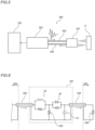
FIG. 1 is a schematic diagram showing a configuration of an ultrasonic inspection system according to a first embodiment of the present invention. -
FIG. 2 is a circuit diagram showing the ultrasonic inspection system according to the first embodiment. -
FIG. 3 is a diagram showing a circuit equivalent toFIG. 2 in transmission of ultrasonic waves. -
FIG. 4 is a diagram showing a circuit equivalent toFIG. 2 in reception of the ultrasonic waves. -
FIG. 5 is a schematic diagram showing a configuration of an ultrasonic inspection system according to a second embodiment of the present invention. -
FIG. 6 is a circuit diagram showing the ultrasonic inspection system according to the second embodiment. -
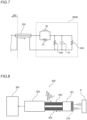
FIG. 7 is a diagram showing a circuit equivalent toFIG. 6 in transmission of ultrasonic waves. -
FIG. 8 is a schematic diagram showing a configuration of an ultrasonic inspection system according to a third embodiment of the present invention. -
FIG. 9 is a circuit diagram showing the ultrasonic inspection system according to the third embodiment. -
FIG. 10 is a schematic diagram showing a configuration of an ultrasonic transducer according to a modified example in first to third embodiments of the present invention. - Embodiments embodying the present invention will be described with reference to the drawings.
- The following description describes configurations of an
ultrasonic inspection system 100 and anultrasonic transducer 101 according to a first embodiment with reference toFIGS. 1 to 4 . In theultrasonic inspection system 100, an inspection target P is inspected by emitting ultrasonic waves toward the inspection target P and detecting the waves that are reflected from the inspection target P. Theultrasonic inspection system 100 is used for ultrasonic diagnosis, non-destructive ultrasonic inspection, etc., for example. - As shown in
FIG. 1 , theultrasonic inspection system 100 according to the first embodiment includes theultrasonic transducer 101, apulser receiver 102, acable 103, acable 104 and ananalyzer 105. Thepulser receiver 102 is an example of an "ultrasonic transceiver" in the claims. Also, thecable 103 and thecable 104 are an example of an "input transmission path" and an example of an "output transmission path", respectively, in the claims. - The
pulser receiver 102 is configured to output (transmit) input waves (transmission pulses) to theultrasonic transducer 101 through thecable 103. Also, thepulser receiver 102 is configured to acquire (receive) detection signals (reception pulses) from theultrasonic transducer 101 through thecable 104. Thepulser receiver 102 includes a transceiver circuit (not shown) including an amplifier, etc., and can amplify the detection signals and output the amplified detection signals to theanalyzer 105. Theanalyzer 105 is configured to generate a test result of the inspection target P by analyzing the detection signals from thepulser receiver 102. For example, theanalyzer 105 is a personal computer (PC) used by inspection operators who inspect the inspection target. - The
cable 103 is a transmission path through which input waves are input from thepulser receiver 102 to theultrasonic transducer 101. Thecable 104 is a transmission path that is provided separately from thecable 103 and configured to output (receive) the detection signal from theultrasonic transducer 101. For example, thecable 103 and thecable 104 are coaxial cables. Also, in the first embodiment, a characteristic impedance of thecable 103 is substantially equal to a characteristic impedance of thecable 104 in magnitude. For example, thecable 103 and thecable 104 have a characteristic impedance of approximately 50 [Ω]. - As shown in
FIG. 2 , theultrasonic transducer 101 includes apiezoelectric element 10, aparallel circuit 20, and a cut-off circuit 30. Theultrasonic transducer 101 includes connectors (not shown) through which the ultrasonic transducer is connected to thecables - The
piezoelectric element 10 is configured to produce ultrasonic waves in accordance with the input waves (transmission pulses) input from thepulser receiver 102. Thepiezoelectric element 10 is configured to output detection signals by detecting the reflection waves (ultrasonic echo) reflected from the inspection target P. Specifically, thepiezoelectric element 10 has a structure in which a piezoelectric piece (piezoelectric material) is sandwiched between a pair of electrodes. Thepiezoelectric element 10 is configured to emit (produce) ultrasonic waves in response to an alternating voltage or pulse voltage that is applied as the input waves to the pair of electrodes. Thepiezoelectric element 10 is configured to output electrical signals as the detection signals in response to ultrasonic oscillation that propagates in the piezoelectric body. For example, the piezoelectric piece (piezoelectric material) is a polymeric material such as vinylidene fluoridetrifluoroethylene copolymer (P(VDF-TrFE)). In addition, thepiezoelectric element 10 has a predetermined capacitance, and serves as an electrical element almost equivalent to a capacitor. InFIG. 2 , thepiezoelectric element 10 is shown as a capacitor. - The
parallel circuit 20 includes aresistor element 21 and aninductor 22, which are connected in parallel to each other. Theparallel circuit 20 is connected to an input side (cable 103 side) of thepiezoelectric element 10. A resistance value of theresistor element 21 is approximately 50 [Ω], for example. In theultrasonic transducer 101 according to the first embodiment, a constant-resistance circuit is constructed of at least thepiezoelectric element 10 and theparallel circuit 20. The constant-resistance circuit will be described later. - The cut-
off circuit 30 of theultrasonic transducer 101 includes a pair ofdiodes off circuit 30 is connected between thepiezoelectric element 10 and theparallel circuit 20. The pair ofdiodes diode 31 is connected to the input side (cable 103 side), and a cathode of thediode 31 is connected an output side (cable 104 side). Contrary to thediode 31, an anode of thediode 32 is connected to the output side, and a cathode of thediode 32 is connected the input side. - The
ultrasonic transducer 101 according to the first embodiment is configured to produce the ultrasonic waves in response to the input waves that are input from thepulser receiver 102 through thecable 103 to thepiezoelectric element 10 through theparallel circuit 20 and the cut-off circuit 30. In addition, theultrasonic transducer 101 according to the first embodiment is configured to output the detection signals from thepiezoelectric element 10 to thepulser receiver 102 through thecable 104, which is different from thecable 103, without passing the detection signals through theparallel circuit 20. - Specifically, the cut-
off circuit 30 of theultrasonic transducer 101 is configured to pass the input waves from thepulser receiver 102 through theparallel circuit 20 so as to input the input waves to thepiezoelectric element 10. Also, the cut-off circuit 30 is configured to prevent passage of the detection signals from thepiezoelectric element 10 through theparallel circuit 20 so as to output the detection signals to thepulser receiver 102 without passing the detection signals through theparallel circuit 20. - The
diodes diodes diodes diodes piezoelectric element 10 is still much smaller than the forward voltage. Accordingly, thediodes diodes diodes diodes diodes diodes piezoelectric element 10 irrespective of a polarity of the input waves. - The
piezoelectric element 10 is configured to transmit and receive ultrasonic waves of relatively high frequencies from several hundred kHz to several hundred MHz. Because the input waves transmitted to thepiezoelectric element 10 has a pulse voltage or an alternating voltage having a high frequency component, in order to suppress loss of transmission to thepiezoelectric element 10 even in a case of such a high frequency component, it is preferable that switching time (reverse recovery time) of thediodes diodes - In addition, a
termination resistor 40 is provided on apulser receiver 102 side. Thetermination resistor 40 is provided for impedance matching for thecable 104. That is, thetermination resistor 40 has a resistance value substantially equal to the characteristic impedance of thecable 104 in magnitude. For example, in the case in which the characteristic impedance of thecable 104 is approximately 50 [Ω], the resistance value of thetermination resistor 40 is approximately 50 [Ω]. In the first embodiment, thepiezoelectric element 10 is connected in parallel to thetermination resistor 40, and is configured to output the detection signals to thepulser receiver 102 through thecable 104. - As shown in
FIG. 3 , in transmission of the ultrasonic waves (in input of the input waves), because the voltage value of the input waves is greater than the forward voltages of thediodes diodes off circuit 30 can be considered a conductor. Thecable 104 is terminated by thetermination resistor 40. Accordingly, because the output side is equivalent to a pure resistor that is the same as thetermination resistor 40 and is connected to in parallel to thepiezoelectric element 10 from the viewpoint of theultrasonic transducer 101, an equivalent circuit toFIG. 2 in the transmission of the ultrasonic waves can be represented by a circuit shown inFIG. 3 . - In the first embodiment, the constant-resistance circuit is constructed of the
piezoelectric element 10, theresistor element 21 and theinductor 22 of theparallel circuit 20, and an output impedance (termination resistor 40). Here, the "output impedance" refers to impedance (the impedance of thetermination resistor 40 and the cable 104) connected on the output side in parallel to the piezoelectric element 10 (capacitor). In the first embodiment, the output impedance is equivalent to thetermination resistor 40 connected in parallel to the piezoelectric element as described above. - Specifically, in the first embodiment, the resistance value of the
resistor element 21 of theparallel circuit 20 and the resistance value of thetermination resistor 40 are substantially equal to the characteristic impedance of the cable 103 (approximately 50 Ω). In the first embodiment, a product Zc·Zl of an impedance Zc of thepiezoelectric element 10 and an impedance Zl of theinductor 22 of theparallel circuit 20 is substantially equal to the square of the characteristic impedance of thecable 103. Accordingly, where a resistance value of each of theresistor element 21 and thetermination resistor 40 is R, the product Zc·Zl of the impedance Zc of thepiezoelectric element 10 and the impedance Zl of theinductor 22 is designed to be substantially equal to a product of the resistance value R of theresistor element 21 and the resistance value R of the termination resistor 40 (to satisfy a relation of Zc·Zl = R2). - If the relationship of Zc·Zl = R2 is satisfied, the
piezoelectric element 10, the parallel circuit 20 (resistor element 21 and inductor 22), and thetermination resistor 40 form the constant-resistance circuit. A combined impedance of the constant-resistance circuit becomes R (50 [Ω]). The combined impedance of constant-resistance circuit is independent of frequencies, and as a result becomes equivalent to a pure resistor. Also, thepiezoelectric element 10 and theinductor 22 of theparallel circuit 20 are said to be inverse in the resistance value R (50 Ω). Specifically, where a predetermined capacitance (capacitance) of thepiezoelectric element 10 is C and an inductance of theinductor 22 is L, Zc and ZI are represented by Zc = 1/jwC and Zl = jwL, respectively. Here, ω = 2nf, and f is a frequency. Because Zc·Zl can be represented by Zc·Zl = L/C, if L/C = R2 is satisfied, the constant-resistance circuit can be formed. For example, in a case in which the predetermine capacitance C of thepiezoelectric element 10 is approximately 11 [pF] and the inductance L of theinductor 22 is approximately 27 [NH], the relation of L (27 [nH]) × 1/C (1/11 [pF]) ≈ 50 [Ω] × 50 [Ω] is satisfied. Accordingly, the constant-resistance circuit (a part R100 indicated by a dotted box inFIG. 3 ) can be formed in theultrasonic transducer 101 by theresistor element 21 and theinductor 22, which are connected in parallel to each other, and thepiezoelectric element 10 and thetermination resistor 40, which are connected in parallel to each other, in the transmission of the ultrasonic waves. As a result, the combined impedance of the constant-resistance circuit becomes approximately 50 [Ω], which is substantially equal to the characteristic impedance of thecable 103. - Consequently, an
ultrasonic transducer 101 side becomes substantially equivalent to a pure resistor of 50 [Ω] from the viewpoint of thepulser receiver 102 side (cable 103 side). In other words, theultrasonic inspection system 100 is configured to input the input waves to theultrasonic transducer 101 through thecable 103 while impedance matching for thecable 103 is performed. - In reception of ultrasonic waves (in the output of the detection signals), an electromotive force from the
piezoelectric element 10 produced by the reflected wave (ultrasonic echo) is small. In a case in which voltages of the detection signals from thepiezoelectric element 10 are smaller than the forward voltages of thediodes diodes off circuit 30 so that a part provided on the input side with respect to the cut-off circuit 30 is electrically separated. Accordingly, a circuit equivalent to the circuit ofFIG. 2 in the reception of the ultrasonic waves can be represented by a circuit diagram shown inFIG. 4 . - Consequently, as shown in
FIG. 4 , from the viewpoint of apiezoelectric element 10 side, thepulser receiver 102 side is equivalent to the circuit that includes a pure resistor of 50 Ω (termination resistor 40) connected to thepiezoelectric element 10 side. In other words, theultrasonic inspection system 100 is configured to output the detection signals from theultrasonic transducer 101 to thepulser receiver 102 without passing the detection signals through theparallel circuit 20 while impedance matching for thecable 104 is performed. - In the
ultrasonic inspection system 100 and theultrasonic transducer 101 according to the first embodiment, the following advantages are obtained. - In the first embodiment, as described above, ultrasonic waves are produced in response to input waves that are input from the pulser receiver 102 (ultrasonic transceiver) through the cable 103 (input transmission path) to the
piezoelectric element 10 through theparallel circuit 20. Also, detection signals are output from thepiezoelectric element 10 to thepulser receiver 102 through the cable 104 (output transmission path), which is different from thecable 103, without passing through theparallel circuit 20. Accordingly, the input waves can be input to thepiezoelectric element 10 through theparallel circuit 20, which is included in the constant-resistance circuit for impedance matching, while the detection signals can be output without passing through theparallel circuit 20, which includes theresistor element 21 and theinductor 22. For this reason, as compared with a case in which signals are transmitted and received through theparallel circuit 20 both in input and output of the signals, insertion loss occurs only in the input of the signals so that reduction of intensity of the output detection signals can be suppressed. Consequently, it is possible to suppress the reduction of the intensity of the detection signals even in a case in which the constant-resistance circuit is provided for impedance matching. - In addition, in the first embodiment, as described above, the cut-
off circuit 30 connected between thepiezoelectric element 10 and theparallel circuit 20 is provided, and the cut-off circuit 30 is configured to pass the input waves through theparallel circuit 20 so as to input the input waves from the pulser receiver 102 (ultrasonic transceiver) to thepiezoelectric element 10, and to cut off the detection signals so as to output the detection signals from thepiezoelectric element 10 to thepulser receiver 102 without the detection signals passing through theparallel circuit 20. Accordingly, the detection signals from thepiezoelectric element 10 can be output without passing through theparallel circuit 20, which is included in the constant-resistance circuit, by cutting off the detection signals that pass through the constant-resistance circuit by using the cut-off circuit 30, and as a result it is possible to easily suppress the reduction of the intensity of the detection signals that are output from thepiezoelectric element 10. - Also, in the first embodiment, as described above, the cut-
off circuit 30 includes the pair ofdiodes diodes off circuit 30, while when a voltage smaller than the forward voltage is applied, the detection signals can be cut off by thecutoff circuit 30 irrespective of a polarity of the voltage. As a result, the pair ofdiodes piezoelectric element 10, and can cut off the detection signals that have a voltage value smaller than the forward voltage. Consequently, because the detection signals from thepiezoelectric element 10 can be output so as to output the detection signals only through the cable 104 (output transmission path) without influence of theparallel circuit 20, which is included in the constant-resistance circuit, by a simple configuration of the pair ofdiodes cutoff circuit 30 such as a switching circuit, it is possible to more easily suppress the reduction of the intensity of the detection signals that are output from thepiezoelectric element 10. - In the first embodiment, as described above, the
piezoelectric element 10 is connected in parallel to thetermination resistor 40, which is provided on the pulser receiver 102 (ultrasonic transceiver) side for impedance matching for the cable 104 (output transmission path), and is configured to output the detection signals to thepulser receiver 102 through thecable 104. In addition, a product of an impedance Zc of thepiezoelectric element 10 and an impedance Zl of theinductor 22 of theparallel circuit 20 is substantially equal to the square of the characteristic impedance of the cable 103 (input transmission path). Accordingly, the constant-resistance circuit can be constructed of theresistor element 21 and theinductor 22 of theparallel circuit 20, thepiezoelectric element 10, and thetermination resistor 40 of thecable 104 in transmission of ultrasonic waves (in the input of the detection signals), while the detection signals can be output through thecable 104 terminated by thetermination resistor 40 without passing through theparallel circuit 20, which includes theresistor element 21 and theinductor 22, in reception of ultrasonic waves (in the output of the detection signals). Accordingly, theresistor element 21 and theinductor 22 of theparallel circuit 20, thepiezoelectric element 10, and thetermination resistor 40 of thecable 104 can be used for impedance matching both in the input and the output of the detection signals. Consequently, the reduction of the intensity of the detection signals can be suppressed by outputting the detection signals without passing the detection signals through theparallel circuit 20 while performing impedance matching both in the input and the output of the detection signals. - In the first embodiment, as described above, the
piezoelectric element 10 is configured to output the detection signals to the pulser receiver 102 (ultrasonic transceiver) through the cable 104 (output transmission path) a characteristic impedance of which is substantially equal to the characteristic impedance of the cable 103 (input transmission path) in magnitude. The constant-resistance circuit, which is formed of at least thepiezoelectric element 10 and theparallel circuit 20, has a combined impedance substantially equal to the characteristic impedance of thecable 103. Accordingly, because the characteristic impedance of thecable 103 is substantially equal to the characteristic impedance of thecable 104 in magnitude, thecable 103 and thecable 104 can be constructed of a common type of coaxial cable, etc. Accordingly, thecable 103 and thecable 104 to be connected to the ultrasonic transducer can be easily maintained and preserved. Also, in this configuration in which the constant-resistance circuit is constructed of thetermination resistor 40 provided for impedance matching for thecable 104 together with theparallel circuit 20 and thepiezoelectric element 10, because the characteristic impedance of thecable 103 is substantially equal to the characteristic impedance of thecable 104 in magnitude, the constant-resistance circuit for impedance matching for thecable 103 can be easily provided. - The following description describes configurations of an
ultrasonic inspection system 200 and anultrasonic transducer 201 according to a second embodiment with reference toFIGS. 5 to 7 . In the second embodiment, dissimilar to the first embodiment in which characteristic impedances of thecables cables - As shown in
FIG. 5 , theultrasonic inspection system 200 according to the second embodiment includes anultrasonic transducer 201, apulser receiver 202, acable 203, and acable 204. Thepulser receiver 202 is an example of an "ultrasonic transceiver" in the claims. Also, thecable 203 and thecable 204 are an example of an "input transmission path" and an example of an "output transmission path", respectively, in the claims. - For example, the
cable 203 and thecable 204 are coaxial cables similar to thecable 103 and thecable 104 in the first embodiment. Thecable 203 is a transmission path through which input waves are transmitted from thepulser receiver 202 to theultrasonic transducer 201. Thecable 204 is a transmission path that is provided separately from thecable 203 and configured to output (receive) the detection signal from theultrasonic transducer 201. In the second embodiment, the characteristic impedance of thecable 204 is greater than the characteristic impedance of thecable 203. For example, the characteristic impedance of thecable 203 is approximately 50 [Ω]. The characteristic impedance of thecable 204 is approximately 75 [Ω]. - The
pulser receiver 202 is configured to output (transmit) input waves (transmission pulses) to theultrasonic transducer 201 through thecable 203, and to acquire (receive) detection signals (reception pulses) from theultrasonic transducer 201 through thecable 204 similar to thepulser receiver 102 in the first embodiment. Thepulser receiver 202 is configured to output the amplified detection signals to theanalyzer 105. - As shown in
FIG. 6 , thepulser receiver 202 includes atermination resistor 240. Thetermination resistor 240 is provided for impedance matching between thecable 204 and thepulser receiver 202 similar to thetermination resistor 40 in the first embodiment. That is, thetermination resistor 240 has a resistance value substantially equal to the characteristic impedance of thecable 204 in magnitude. Accordingly, in a case in which the characteristic impedance of thecable 204 is approximately 75 [Ω], the resistance value of thetermination resistor 240 is also approximately 75 [Ω]. - The
ultrasonic transducer 201 in the second embodiment includes aresistor element 250 in addition to thepiezoelectric element 10, theparallel circuit 20, and the cut-off circuit 30. Configurations of thepiezoelectric element 10, theparallel circuit 20, and the cut-off circuit 30 are similar to those in the first embodiment. Theresistor element 250 is an example of a "combining resistor element" in the claims. - In the second embodiment, the
resistor element 250 is connected in parallel to thepiezoelectric element 10 on the input side of thepiezoelectric element 10. Specifically, theresistor element 250 is connected in parallel to thepiezoelectric element 10 on the input side with respect to the cut-off circuit 30. In the second embodiment, a constant-resistance circuit (a part indicated by a dotted box R200 inFIG. 7 ) is formed by a combined resistance of theresistor element 250 and an output impedance (termination resistor 240) together with thepiezoelectric element 10 and theparallel circuit 20 in transmission of ultrasonic waves. - As shown in
FIG. 7 , in the transmission of ultrasonic waves (in the input of the detection signals), the cut-off circuit 30 can be considered as a conductor similar to the first embodiment. Thecable 204 is terminated by thetermination resistor 240. Accordingly, a circuit equivalent to the circuit inFIG. 6 in the transmission of the ultrasonic waves can be represented by a circuit diagram shown inFIG. 7 . - Because the cut-
off circuit 30 can be considered as a conductor in the transmission of the ultrasonic waves, thetermination resistor 240 and theresistor element 250 in the second embodiment are connected in parallel to each other in the equivalent circuit in the transmission of the ultrasonic waves, and can be represented by a part indicated by the dotted box R200 inFIG. 7 . The combined resistance of thetermination resistor 240 and theresistor element 250, which are connected in parallel to each other in the part indicated by the dotted box R200 inFIG. 7 , is substantially equal to the characteristic impedance of the cable 203 (approximately 50 [Ω]). Specifically, the resistance value of thetermination resistor 240 is approximately 75 Ω, which is substantially equal to the characteristic impedance of thecable 204, and theresistor element 250 has a resistance value of approximately 150 Ω so that the combined resistance of thetermination resistor 240 and theresistor element 250 becomes approximately 50 Ω. Because the resistance value of theresistor element 21 in theparallel circuit 20 is approximately 50 Ω, and the combined resistance of thetermination resistor 240 and theresistor element 250 is also approximately 50 Ω, thepiezoelectric element 10 and theinductor 22 are said to be inverse in the resistance value R (50 Ω) similar to the first embodiment. Accordingly, a constant-resistance circuit similar to the part indicated by the dotted box R100 inFIG. 3 in the first embodiment can be formed in the part indicated by the dotted box R200 inFIG. 7 . In other words, in theultrasonic transducer 201 according to the second embodiment, the constant-resistance circuit a combined impedance of which is substantially equal to the characteristic impedance of thecable 203 is constructed of thepiezoelectric element 10, theparallel circuit 20, theresistor element 250, and an output impedance (termination resistor 240). - Consequently, an
ultrasonic transducer 201 side becomes substantially equivalent to a pure resistor of 50 [Ω] from the viewpoint of thepulser receiver 202 side (cable 203 side). In other words, similar to theultrasonic inspection system 100 according to the first embodiment, theultrasonic inspection system 200 is configured to input the input waves to theultrasonic transducer 201 through thecable 203 while impedance matching for thecable 203 is performed. - In the reception of ultrasonic waves (in the output of the detection signals), similar to the first embodiment, the detection signals are cut off by the
cutoff circuit 30 so that a part provided on the input side with respect to the cut-off circuit 30 is electrically separated. Consequently, from the viewpoint of thepiezoelectric element 10 side, thepulser receiver 202 side is equivalent to the circuit that includes a pure resistor of 75 Ω (termination resistor 240) connected to thepiezoelectric element 10 side. In other words, similar to theultrasonic inspection system 100 according to the first embodiment, theultrasonic inspection system 200 is configured to output the detection signals from theultrasonic transducer 201 to thepulser receiver 202 without passing the detection signals through theparallel circuit 20 while impedance matching for thecable 204 is performed. - The other configuration of the second embodiment is similar to the configuration of the first embodiment.
- In the second embodiment, the following advantages are obtained.
- In the second embodiment, as described above, the resistor element 250 (combining resistor element) is included in the constant-resistance circuit in addition to the
piezoelectric element 10 and theparallel circuit 20, and connected in parallel to thepiezoelectric element 10. Also, thepiezoelectric element 10 is configured to output the detection signals to the pulser receiver 202 (ultrasonic transceiver) through the cable 204 (output transmission path) a characteristic impedance of which is greater than the characteristic impedance of the cable 203 (input transmission path) in magnitude. Also, the constant-resistance circuit, which includes thepiezoelectric element 10, theparallel circuit 20 and theresistor element 250, has a combined impedance substantially equal to the characteristic impedance of thecable 203. Accordingly, the constant-resistance circuit constructed of thepiezoelectric element 10, theparallel circuit 20 and the combiningresistor element 250 can perform impedance matching in transmission of ultrasonic waves (in the input of the detection signals), while the detection signals can be output through thecable 204 having a characteristic impedance greater than thecable 203 without passing through theparallel circuit 20 in reception of ultrasonic waves (in the output of the detection signals). Accordingly, in addition to an advantage in which insertion loss occurs only in the input of the signals in theparallel circuit 20, the reduction of the intensity of the detection signals from thepiezoelectric element 10 caused by thecable 204 can be suppressed by the characteristic impedance of thecable 204 greater than thecable 203. Consequently, because detection sensitivity of the detection signals from thepiezoelectric element 10 can be further increased, it is possible to further suppress the reduction of the intensity of the detection signals. - The other advantages of the second embodiment are similar to the first embodiment.
- The following description describes configurations of an
ultrasonic inspection system 300 and anultrasonic transducer 301 according to a third embodiment with reference toFIGS. 8 and9 . In the third embodiment, theultrasonic transducer 301 includes a plurality ofpiezoelectric elements 310 dissimilar to the first embodiment in which theultrasonic transducer 101 includes onepiezoelectric element 10. The same components as those of the first embodiment are denoted by the same reference numerals, and their description is omitted. - As shown in
FIG. 8 , theultrasonic inspection system 300 according to the third embodiment includes anultrasonic transducer 301, apulser receiver 302,cables 303,cables 304 and ananalyzer 305. Thepulser receiver 302 is an example of an "ultrasonic transceiver" in the claims. Also, thecables 303 and thecables 304 are examples of a "plurality of input transmission paths" and a "plurality of output transmission paths", respectively, in the claims. - In the third embodiment, the
ultrasonic transducer 301 includes the plurality ofpiezoelectric elements 310, as shown inFIG. 9 . Specifically, theultrasonic transducer 301 includespiezoelectric elements piezoelectric elements 310. For example, the number of thepiezoelectric elements 310 is 64. Each of the plurality ofpiezoelectric elements 310 is configured to produce ultrasonic waves in accordance with the input waves (transmission pulses) input from thepulser receiver 302. Each of the plurality ofpiezoelectric elements 310 is configured to output detection signals by detecting the reflection waves (ultrasonic echo) reflected from the inspection target P. Capacitances of the plurality ofpiezoelectric elements 310 are substantially equal to each other. The plurality ofpiezoelectric elements 310 are aligned in a straight line in theultrasonic transducer 301. In other words, theultrasonic transducer 301 is a linear array transducer for linearly scanning the inspection target P. - In the
ultrasonic inspection system 300 and theultrasonic transducer 301 according to the third embodiment, each of the plurality ofpiezoelectric elements 310 has a configuration for suppressing reduction of sensitivity of the detection signals while performing impedance matching similar to the first and second embodiments. In other words, the plurality ofpiezoelectric elements 310 each of which has the same configuration are combined so that theultrasonic inspection system 300 can linearly scan the inspection target P. - Specifically, as shown in
FIG. 8 , thepulser receiver 302 in the third embodiment has a plurality of (64) channels corresponding to the plurality ofpiezoelectric elements 310. Thepulser receiver 302 outputs (transmits) input waves (transmission pulses) to the plurality ofpiezoelectric elements 310 of theultrasonic transducer 301 through thecables 303 by using the plurality of channels. Thepulser receiver 302 then acquires (receives) the detection signals (reception pulses) from the plurality ofpiezoelectric elements 310 of theultrasonic transducer 301 through thecables 304, which are provided separately from thecables 303, by using the plurality of channels. In other words, thepulser receiver 302 is configured to independently activate the plurality ofpiezoelectric elements 310 so as to separately acquire the detection signals from the plurality ofpiezoelectric elements 310. Theultrasonic transducer 301 includes connectors (not shown) through which the ultrasonic transducer is connected to thecables pulser receiver 302 outputs the detection signals from the plurality ofpiezoelectric elements 310 to theanalyzer 305. Theanalyzer 305 is configured to generate a test result of the inspection target P by analyzing the detection signals from thepulser receiver 302. - As shown in
FIG. 9 , thecable 303 and thecable 304 includescables cables piezoelectric elements 310 and assigned to thepiezoelectric elements cable 303 set and acable 304 set has a bundled structure of the plurality of (64) coaxial cables. Characteristic impedances of the plurality of coaxial cables in both thecable 303 set and thecable 304 set are substantially equal to each other, and are approximately 50 [Ω]. - Also, the
pulser receiver 302 includes termination resistors 340 (termination resistors cables cable 304 set. Each of thetermination resistors 340 has a resistance value (approximately 50 [Ω]) substantially equal to the characteristic impedance of each of thecables 304 similar to thetermination resistor 40 in the first embodiment. - In the third embodiment, the
ultrasonic transducer 301 includes a plurality ofparallel circuits 320, a plurality of cut-offcircuits 330, and a plurality ofcapacitors 360 corresponding to the plurality ofpiezoelectric elements 310. Specifically, theultrasonic transducer 301 includes theparallel circuits off circuits capacitors piezoelectric elements - Each of the plurality of
parallel circuits 320 is connected to an input side of corresponding one of the plurality ofpiezoelectric elements 310. The plurality ofparallel circuit 320 has the same configuration as each other. Specifically, each of the plurality ofparallel circuits 320 includes theresistor element 21 and theinductor 322 connected in parallel to each other similar to theparallel circuit 20 in the first embodiment. Theparallel circuit 320 is connected to the input side (cable 303 side) of thepiezoelectric element 310. A resistance value of theresistor element 21 is approximately 50 [Ω], for example. In theultrasonic transducer 301 according to the third embodiment, each of the constant-resistance circuits is constructed of corresponding one of thepiezoelectric elements 310, corresponding one of thecapacitors 360, and corresponding one of theparallel circuits 320. The constant-resistance circuit will be described later. - Each of the plurality of cut-off
circuits 330 includes a pair of diodes connected in parallel to each other with polarities of the diodes being opposite to each other similar to the first embodiment. The cut-off circuit 330 is connected between thepiezoelectric element 310 and theparallel circuit 320. The cut-offcircuits 330 have the same configuration as each other. Thecutoff circuit 330 is configured to pass the input waves through thediodes diodes diodes off circuit 30 in the first embodiment. - Each of the plurality of
capacitors 360 is connected in parallel to corresponding one of the plurality ofpiezoelectric elements 310. In a linear array probe, because an area of eachpiezoelectric element 310 is small, an impedance of thepiezoelectric element 310 is likely to be high. For this reason, an influence of electromagnetic noises from the surroundings on the detection signals output from thepiezoelectric element 310 will be large. To address this, although sensitivity becomes low, the impedance can be adjusted to a small value by connecting thecapacitor 360 in parallel to thepiezoelectric element 310. - A capacitance of each
capacitor 360 is designed based on a capacitance ofpiezoelectric element 310, a characteristic impedance of thecable 304 on the output side, and a frequency of the input waves. For example, as for thecapacitor 360x connected in parallel to thepiezoelectric element 310x, which is one of the plurality ofpiezoelectric elements 310, a capacitance of thecapacitor 360x is designed so that a combined capacitance Cx of thepiezoelectric element 310x and thecapacitor 360x is expressed by the following equation (1).
[Equation 1]
cable 304. The angular frequency ωu is represented by 2πfu. The frequency fu is preferably selected from a median value a frequency band of the ultrasonic waves output from corresponding one element of thepiezoelectric elements 310 to an upper limit value of the frequency band. Capacitances of the plurality ofcapacitors 360 are equal to each other. That is, as for theother capacitors 360, their capacitances are determined so that a combined capacitance of each capacitor and corresponding one element of thepiezoelectric elements 310 is expressed by a equation similar to the aforementioned Equation (1). - The
ultrasonic transducer 301 according to the third embodiment is configured to produce the ultrasonic waves in response to the input waves that are input from thepulser receiver 302 through thecables 303 to thepiezoelectric elements 310 through the plurality ofparallel circuits 320 in transmission of ultrasonic waves (in the input of the detection signals) similar to the first embodiment. Theultrasonic transducer 301 is configured to output the detection signals from the plurality ofpiezoelectric elements 310 to thepulser receiver 302 through thecables 304 without passing the detection signals through the plurality ofparallel circuits 320 in reception of ultrasonic waves (in output of the detection signals). - Specifically, in the transmission of ultrasonic waves (in the input of the detection signals), each cut-
off circuit 330 can be considered as a conductor similar to the first embodiment. The constant-resistance circuit an impedance of which is substantially equal to the characteristic impedance of the cable 303 (approximately 50 Ω) is constructed of theparallel circuit 320, thepiezoelectric element 310, thecapacitor 360, and an output impedance (termination resistor 340). In other words, a combined circuit of each of the plurality ofpiezoelectric elements 310 and each of the plurality of thecapacitors 360, and each of the plurality of theinductors 322 are said to be inverse in a resistance value R (50 Ω). - More specifically, in the transmission of the ultrasonic waves, the
ultrasonic transducer 301 is designed so that a product of a combined impedance of eachpiezoelectric element 310 and eachcapacitor 360, and the impedance of eachinductor 322 is a square of the characteristic impedance of each cable 303 (a product of a resistance of eachresistor element 21 and a resistance of each termination resistor 340). Accordingly, similar to theultrasonic inspection system 100 according to the first embodiment, theultrasonic inspection system 300 is configured to individually input the input waves to eachpiezoelectric element 310 of theultrasonic transducer 301 through eachcable 303 while impedance matching for eachcable 303 is performed. - In the reception of ultrasonic waves (in the output of the detection signals), similar to the first embodiment, the detection signals are cut off by each
cutoff circuit 330 so that a part provided on the input side with respect to the cut-off circuit 330 is electrically separated. As a result, similar to theultrasonic inspection system 100 according to the first embodiment, theultrasonic inspection system 300 is configured to output the detection signals from eachpiezoelectric element 310 of theultrasonic transducer 301 to thepulser receiver 302 without passing the detection signals through theparallel circuit 320 while impedance matching for eachcable 304 is performed by eachtermination resistor 340. - The other configuration of the third embodiment is similar to the configuration of the first embodiment.
- In the third embodiment, the following advantages are obtained.
- In the third embodiment, as described above, a plurality of
piezoelectric elements 310 are provided; a plurality ofparallel circuits 320 are provided so that the plurality of parallel circuits are connected to input sides of the plurality ofpiezoelectric elements 310 one by one; and the ultrasonic transducer is configured to produce the ultrasonic waves in response to the input waves that are input from the pulser receiver 302 (ultrasonic transceiver) through each of the cables 303 (each of a plurality of input transmission paths) that correspond to the plurality ofpiezoelectric elements 310 to corresponding one of the plurality ofpiezoelectric elements 310 through each of the plurality ofparallel circuits 320, and to output the detection signals from the corresponding one of the plurality ofpiezoelectric elements 310 to thepulser receiver 302 through each of a plurality of cables 304 (output transmission paths) that correspond to the plurality ofpiezoelectric elements 310 without passing the detection signals through corresponding one of the plurality ofparallel circuits 320. Accordingly, even in a case in which a plurality ofpiezoelectric elements 310 are provided, the input waves can be input to thepiezoelectric element 310 through each of theparallel circuits 320, which are included in the constant-resistance circuits for impedance matching, while the detection signals from each of the plurality ofpiezoelectric elements 310 can be output without passing through theparallel circuit 320, which includes theresistor element 21 and theinductor 322. Consequently, a wide area of the inspection target P can be collectively inspected by the plurality ofpiezoelectric elements 310 provided, and the reduction of the intensity of the detection signals output from each of the plurality ofpiezoelectric elements 310 can be suppressed. - In addition, in the third embodiment, a plurality of
capacitors 360 each of which is connected in parallel to corresponding one of the plurality ofpiezoelectric elements 310 are provided. Accordingly, even in a case in which areas of the plurality ofpiezoelectric elements 310 are small so that their impedances are relatively large, each combined impedance can be reduced by eachcapacitor 360 connected in parallel to eachpiezoelectric element 310, and as a result it is possible to reduce influences of electromagnetic noises from the surroundings on the detection signals output from thepiezoelectric elements 310. The other advantages of the third embodiment are similar to the first and second embodiments. - Note that the embodiment disclosed this time must be considered as illustrative in all points and not restrictive. The scope of the present invention is not shown by the above description of the embodiments but by the scope of claims for patent, and all modifications within the meaning and scope equivalent to the scope of claims for patent are further included.
- For example, in the first and third embodiments, the constant-resistance circuit is designed so that resistances of both the termination resistor 40 (340) and the
resistor element 21 of the parallel circuit 20 (320) are equal to characteristic impedances of thecable 103, 303 (input transmission path), and a product of an impedance of the piezoelectric element 10 (310) and an impedance the inductor 22 (322) of the parallel circuit 20 (320) is substantially equal to a square of a characteristic impedance ofcable - While the example in which the
cable 103 or 203 (input transmission path), and thecable 104 or 204 (output transmission path) are separate coaxial cables has been shown in the aforementioned first and second embodiments, the present invention is not limited to this. For example, an input transmission path and an output transmission path can be included in a single cable. In other words, a single cable can include two signal lines as the input transmission path and the output transmission path. While the example in which the cables 303 (a plurality of transmission input paths) and the cables 304 (a plurality of output transmission paths) are separate cables has been shown in the aforementioned third embodiment, the present invention is not limited to this. For example, signal lines that are the plurality of input transmission paths, and signal lines that are the plurality of output transmission paths can be collectively included in a single cable. - While the example in which the ultrasonic transducer 101 (201, 301), the cable(s) 103, 203, 303 (input transmission path, a plurality of input transmission paths), and the cable(s) 104, 204, 304 (output transmission path, a plurality of output transmission paths) are separately constructed from each other, and connected to each other by the connectors has been shown in the aforementioned first to third embodiments, the present invention is not limited to this. For example, the ultrasonic transducer and the cables (input and output transmission paths) can be integrally constructed.
- While the example in which the piezoelectric element 10 (310) has a structure including a piezoelectric piece (piezoelectric material) of a polymeric material has been shown in the aforementioned first to third embodiments, the present invention is not limited to this. For example, the piezoelectric piece of the piezoelectric element can be formed of a ceramic material.
- While the example in which the ultrasonic transducer 101 (201, 301) includes both the piezoelectric element 10 (310) and the parallel circuit 20 (320) has been shown in the aforementioned first to third embodiments, the present invention is not limited to this. For example, the parallel circuit that forms the constant-resistance circuit together with the piezoelectric element can be separately provided from the ultrasonic transducer, and the impedance matching for the input transmission path can be performed by connecting the parallel circuit between the input transmission path and the ultrasonic transducer by using a connector, etc. Also, the cut-
off circuit 30 can be provided separately from the ultrasonic transducer. - While the example in which the cut-
off circuit 30 is constructed of the pair ofdiodes - Alternatively, a cut-
off circuit 430 can be constructed of a pair ofFETs 431 and 432 (field effect transistors), as shown in anultrasonic transducer 401 according to a modified embodiment shown inFIG. 10 . In the cut-off circuit 430 in this modified embodiment, the pair ofFETs FETs diodes - While the example in which the
ultrasonic transducer 301 is a linear array transducer including a plurality ofpiezoelectric elements 310 aligned in a straight line has been shown in the aforementioned third embodiment, the present invention is not limited to this. For example, the ultrasonic transducer can be a multi-array transducer including a plurality of piezoelectric elements arranged in a grid shape (in a plane). - While the example in which the
ultrasonic transducer 301 includes a plurality ofcapacitors 360 each of which is connected in parallel to corresponding one of the plurality ofpiezoelectric elements 310 has been shown in the aforementioned third embodiment, the present invention is not limited to this. For example, in a case in which the plurality of piezoelectric elements are provided, no capacitors that are connected in parallel to the piezoelectric elements can be provided. Also, in a case in which only one piezoelectric element is provided similar to the first and second embodiments, the capacitor can be connected in parallel to the piezoelectric element. - While the example in which capacitances of the plurality of
piezoelectric elements 310 are substantially equal to each other has been shown in the aforementioned third embodiment, the present invention is not limited to this. For example, the plurality ofpiezoelectric elements 310 can have different capacitances from each other. In this case, as for the parallel circuits connected to input sides of the plurality of piezoelectric elements, the plurality of parallel circuit have configurations different from each other. Specifically, impedances of the inductors in the plurality of parallel circuits are designed to form the constant-resistance circuits according to the different capacitances of the plurality of piezoelectric elements. Although it has been illustratively described that characteristic impedances of the transmission paths (coaxial cables) of the cables 303 (plurality of input transmission paths) are substantially equal to each other in the aforementioned third embodiment, the characteristic impedances of input transmission paths can be different from each other. Also, in this case, resistance values of the resistor elements of the parallel circuits are designed according to the different characteristic impedances to perform impedance matching. The same goes for the cables 304 (a plurality of output transmission paths). -
- 10, 310; piezoelectric element
- 20, 320; parallel circuit
- 21; resistor element
- 22, 322; inductor
- 30, 330, 430; cut-off circuit
- 31, 32; diode
- 40, 240, 340; termination resistor
- 100, 200, 300; ultrasonic inspection system
- 101, 201, 301, 401; ultrasonic transducer
- 102, 202, 302; pulser receiver (ultrasonic transceiver)
- 103, 203; cable (input transmission path)
- 104, 204; cable (output transmission path)
- 250; resistor element (combining resistor element)
- 303; cable (input transmission path)
- 304; cable (output transmission path)
Claims (8)
- An ultrasonic transducer comprising:a piezoelectric element configured to produce ultrasonic waves based on input waves input from an ultrasonic transceiver and to output detection signals to the ultrasonic transceiver by detecting the waves reflected from an inspection target;a parallel circuit including a resistor element and an inductor connected in parallel to each other, and connected to an input side of the piezoelectric element, whereinat least the piezoelectric element and the parallel circuit form a constant-resistance circuit, andthe ultrasonic waves are produced in response to the input waves that are input from the ultrasonic transceiver through an input transmission path to the piezoelectric element through the parallel circuit, and the detection signals are output from the piezoelectric element to the ultrasonic transceiver through an output transmission path that is different from the input transmission path without passing through the parallel circuit.
- The ultrasonic transducer according to claim 1 further comprising a cut-off circuit connected between the piezoelectric element and the parallel circuit, wherein
the cut-off circuit is configured to pass the input waves through the parallel circuit so as to input the input waves from the ultrasonic transceiver to the piezoelectric element, and to cut off the detection signals so as to output the detection signals from the piezoelectric element to the ultrasonic transceiver without passing the detection signals through the parallel circuit. - The ultrasonic transducer according to claim 2,
whereinthe cut-off circuit includes a pair of diodes connected in parallel to each other with polarities of the diodes being opposite to each other; andforward voltages of the pair of diodes are substantially equal to each other in magnitude. - The ultrasonic transducer according to any of claims 1 to 3, whereinthe piezoelectric element is connected in parallel to a termination resistor that is provided on the ultrasonic transceiver side for impedance matching for the output transmission path, and is configured to output the detection signals to the ultrasonic transceiver through the output transmission path; anda product of an impedance of the piezoelectric element and an impedance of the inductor in the parallel circuit is substantially equal to a square of a characteristic impedance of the input transmission path.
- The ultrasonic transducer according to any of claims 1 to 4, whereinthe piezoelectric element is configured to output the detection signals to the ultrasonic transceiver through the output transmission path a characteristic impedance of which is substantially equal to a/the characteristic impedance of the input transmission path in magnitude; andthe constant-resistance circuit, which is formed of at least the piezoelectric element and the parallel circuit, has a combined impedance substantially equal to the characteristic impedance of the input transmission path.
- The ultrasonic transducer according to any of claims 1 to 4 further comprising a combining resistor element included in the constant-resistance circuit in addition to the piezoelectric element and the parallel circuit, and connected in parallel to the piezoelectric element,
whereinthe piezoelectric element is configured to output the detection signals to the ultrasonic transceiver through the output transmission path a characteristic impedance of which is greater than a/the characteristic impedance of the input transmission path; andthe constant-resistance circuit, which includes the piezoelectric element, the parallel circuit and the combining resistor element, has a combined impedance substantially equal to the characteristic impedance of the input transmission path. - The ultrasonic transducer according to any of claims 1 to 6 further comprising a plurality of piezoelectric elements as the piezoelectric element, whereina plurality of parallel circuits are provided as the parallel circuit so that the plurality of parallel circuits are connected to input sides of the plurality of piezoelectric elements one by one; andthe ultrasonic waves are produced in response to the input waves that are input from the ultrasonic transceiver through each of a plurality of input transmission paths that are provided as the input transmission path and correspond to the plurality of piezoelectric elements to corresponding one of the plurality of piezoelectric elements through each of the plurality of parallel circuits, and the detection signals are output from the corresponding one of the plurality of piezoelectric elements to the ultrasonic transceiver through each of a plurality of output transmission paths that are provided as the output transmission path and correspond to the plurality of piezoelectric elements without passing the detection signals through corresponding one of the plurality of parallel circuits.
- An ultrasonic inspection system comprising:an ultrasonic transducer that includes a piezoelectric element configured to produce ultrasonic waves based on input waves input to the piezoelectric element, and to output detection signals by detecting the waves reflected from an inspection target;an input transmission path configured to transmit the input waves to the ultrasonic transducer;an output transmission path provided separately from the input transmission path, and configured to output the detection signals output from the ultrasonic transducer; andan ultrasonic transceiver configured to output the input waves to the ultrasonic transducer through the input transmission path, and to acquire the detection signals from the ultrasonic transducer through the output transmission path, whereina constant-resistance circuit is formed of at least the piezoelectric element of the ultrasonic transducer, and a parallel circuit that includes a resistor element and an inductor connected in parallel to each other and is connected to an input side of the piezoelectric element; andthe ultrasonic transducer is configured to produce the ultrasonic waves in response to the input waves that are input from the ultrasonic transceiver through the input transmission path to the piezoelectric element through the parallel circuit, and to output the detection signals from the piezoelectric element to the ultrasonic transceiver through the output transmission path, which is different from the input transmission path, without passing the detection signals through the parallel circuit.
Applications Claiming Priority (2)
| Application Number | Priority Date | Filing Date | Title |
|---|---|---|---|
| JP2021143298A JP7564070B2 (en) | 2021-09-02 | 2021-09-02 | Ultrasonic Transducers and Ultrasonic Inspection Systems |
| PCT/JP2022/032987 WO2023033112A1 (en) | 2021-09-02 | 2022-09-01 | Ultrasonic transducer and ultrasonic inspection system |
Publications (2)
| Publication Number | Publication Date |
|---|---|
| EP4398600A1 true EP4398600A1 (en) | 2024-07-10 |
| EP4398600A4 EP4398600A4 (en) | 2025-08-27 |
Family
ID=85412373
Family Applications (1)
| Application Number | Title | Priority Date | Filing Date |
|---|---|---|---|
| EP22864694.9A Pending EP4398600A4 (en) | 2021-09-02 | 2022-09-01 | ULTRASONIC TRANSDUCERS AND ULTRASONIC TESTING SYSTEMS |
Country Status (3)
| Country | Link |
|---|---|
| EP (1) | EP4398600A4 (en) |
| JP (1) | JP7564070B2 (en) |
| WO (1) | WO2023033112A1 (en) |
Family Cites Families (5)
| Publication number | Priority date | Publication date | Assignee | Title |
|---|---|---|---|---|
| US5269189A (en) * | 1988-04-13 | 1993-12-14 | Iowa State University Research Foundation, Inc. | Method and means of transmitting and receiving broad-band unipolar, ultrasonic pulses for ultrasonic inspection |
| JP2001086587A (en) * | 1999-09-10 | 2001-03-30 | Tokimec Inc | Ultrasonic wave transducer |
| JP6259584B2 (en) | 2013-04-18 | 2018-01-10 | 東レエンジニアリング株式会社 | Ultrasonic transducer |
| WO2018081793A1 (en) | 2016-10-31 | 2018-05-03 | Northeastern University | Reconfigurable implantable medical system for ultrasonic power control and telemetry |
| JP2021019927A (en) * | 2019-07-29 | 2021-02-18 | 京セラ株式会社 | Ultrasonic probe and ultrasonic detection device |
-
2021
- 2021-09-02 JP JP2021143298A patent/JP7564070B2/en active Active
-
2022
- 2022-09-01 EP EP22864694.9A patent/EP4398600A4/en active Pending
- 2022-09-01 WO PCT/JP2022/032987 patent/WO2023033112A1/en not_active Ceased
Also Published As
| Publication number | Publication date |
|---|---|
| JP7564070B2 (en) | 2024-10-08 |
| JP2023036312A (en) | 2023-03-14 |
| WO2023033112A1 (en) | 2023-03-09 |
| EP4398600A4 (en) | 2025-08-27 |
Similar Documents
| Publication | Publication Date | Title |
|---|---|---|
| US6050945A (en) | Ultrasound front-end circuit combining the transmitter and automatic transmit/receive switch with agile power level control | |
| JP4810092B2 (en) | Integrated low-voltage transmit / receive switch for ultrasonic imaging systems | |
| US6083164A (en) | Ultrasound front-end circuit combining the transmitter and automatic transmit/receiver switch | |
| US5603324A (en) | Duplexer including a field-effect transistor for use in an ultrasound imaging system | |
| CN101264024B (en) | Ultrasonic image acquisition device | |
| KR101142678B1 (en) | Layer switching for an ultrasound transducer array | |
| US9157990B2 (en) | Ultrasonic transmitting/receiving circuit and ultrasonic diagnostic apparatus | |
| Sun et al. | A 180-V pp integrated linear amplifier for ultrasonic imaging applications in a high-voltage CMOS SOI technology | |
| EP4398600A1 (en) | Ultrasonic transducer and ultrasonic inspection system | |
| JPS6384531A (en) | Ultrasonic diagnostic apparatus | |
| US6269052B1 (en) | Transmitting/receiving circuit and transmitting/receiving method for a transducer | |
| KR20220066428A (en) | Device for actuating and reading a group of ultrasound transducers for ultrasound computer tomography, and ultrasound computer tomography machine | |
| EP1640744A1 (en) | Ultrasonic diagnostic apparatus with low voltage switch in the receive channel | |
| CN1957851B (en) | Ultrasonic probe and ultrasonic diagnostic apparatus | |
| JP2018023774A (en) | Ultrasonic probe and subject information acquisition apparatus | |
| US5609154A (en) | Duplexer including a variable capacitance diode for an ultrasound imaging system | |
| US5511424A (en) | Remote preamplifier and impedance matching circuit for electromagnetic acoustic transducer | |
| US5449958A (en) | Diode expander for electromagnetic acoustic transducer electronics | |
| WO2017212308A1 (en) | Harmonic ultrasound imaging | |
| JP2004097588A (en) | Ultrasonograph | |
| JP2758192B2 (en) | Ultrasound diagnostic equipment | |
| JP2019114954A (en) | Driving circuit | |
| JP4877572B2 (en) | sampler | |
| JP3808845B2 (en) | Ultrasonic diagnostic equipment | |
| JPH0136131Y2 (en) |
Legal Events
| Date | Code | Title | Description |
|---|---|---|---|
| STAA | Information on the status of an ep patent application or granted ep patent |
Free format text: STATUS: THE INTERNATIONAL PUBLICATION HAS BEEN MADE |
|
| PUAI | Public reference made under article 153(3) epc to a published international application that has entered the european phase |
Free format text: ORIGINAL CODE: 0009012 |
|
| STAA | Information on the status of an ep patent application or granted ep patent |
Free format text: STATUS: REQUEST FOR EXAMINATION WAS MADE |
|
| 17P | Request for examination filed |
Effective date: 20240328 |
|
| AK | Designated contracting states |
Kind code of ref document: A1 Designated state(s): AL AT BE BG CH CY CZ DE DK EE ES FI FR GB GR HR HU IE IS IT LI LT LU LV MC MK MT NL NO PL PT RO RS SE SI SK SM TR |
|
| DAV | Request for validation of the european patent (deleted) | ||
| DAX | Request for extension of the european patent (deleted) | ||
| A4 | Supplementary search report drawn up and despatched |
Effective date: 20250728 |
|
| RIC1 | Information provided on ipc code assigned before grant |
Ipc: H04R 3/00 20060101AFI20250722BHEP Ipc: H04R 17/00 20060101ALI20250722BHEP Ipc: A61B 8/00 20060101ALI20250722BHEP Ipc: G01N 29/22 20060101ALI20250722BHEP Ipc: G01S 7/526 20060101ALI20250722BHEP Ipc: B06B 1/02 20060101ALI20250722BHEP |
|
| GRAP | Despatch of communication of intention to grant a patent |
Free format text: ORIGINAL CODE: EPIDOSNIGR1 |
|
| STAA | Information on the status of an ep patent application or granted ep patent |
Free format text: STATUS: GRANT OF PATENT IS INTENDED |
|
| INTG | Intention to grant announced |
Effective date: 20260311 |