EP4398529A1 - Wireless communication system, wireless communication method, and receiver device - Google Patents
Wireless communication system, wireless communication method, and receiver device Download PDFInfo
- Publication number
- EP4398529A1 EP4398529A1 EP21956041.4A EP21956041A EP4398529A1 EP 4398529 A1 EP4398529 A1 EP 4398529A1 EP 21956041 A EP21956041 A EP 21956041A EP 4398529 A1 EP4398529 A1 EP 4398529A1
- Authority
- EP
- European Patent Office
- Prior art keywords
- signal
- unit
- basis
- reception device
- equalization
- Prior art date
- Legal status (The legal status is an assumption and is not a legal conclusion. Google has not performed a legal analysis and makes no representation as to the accuracy of the status listed.)
- Granted
Links
Images




Classifications
-
- H—ELECTRICITY
- H04—ELECTRIC COMMUNICATION TECHNIQUE
- H04L—TRANSMISSION OF DIGITAL INFORMATION, e.g. TELEGRAPHIC COMMUNICATION
- H04L25/00—Baseband systems
- H04L25/38—Synchronous or start-stop systems, e.g. for Baudot code
- H04L25/40—Transmitting circuits; Receiving circuits
- H04L25/49—Transmitting circuits; Receiving circuits using code conversion at the transmitter; using predistortion; using insertion of idle bits for obtaining a desired frequency spectrum; using three or more amplitude levels ; Baseband coding techniques specific to data transmission systems
- H04L25/4917—Transmitting circuits; Receiving circuits using code conversion at the transmitter; using predistortion; using insertion of idle bits for obtaining a desired frequency spectrum; using three or more amplitude levels ; Baseband coding techniques specific to data transmission systems using multilevel codes
-
- H—ELECTRICITY
- H04—ELECTRIC COMMUNICATION TECHNIQUE
- H04B—TRANSMISSION
- H04B1/00—Details of transmission systems, not covered by a single one of groups H04B3/00 - H04B13/00; Details of transmission systems not characterised by the medium used for transmission
- H04B1/06—Receivers
- H04B1/10—Means associated with receiver for limiting or suppressing noise or interference
- H04B1/12—Neutralising, balancing, or compensation arrangements
- H04B1/123—Neutralising, balancing, or compensation arrangements using adaptive balancing or compensation means
-
- H—ELECTRICITY
- H04—ELECTRIC COMMUNICATION TECHNIQUE
- H04L—TRANSMISSION OF DIGITAL INFORMATION, e.g. TELEGRAPHIC COMMUNICATION
- H04L25/00—Baseband systems
- H04L25/02—Details ; arrangements for supplying electrical power along data transmission lines
- H04L25/03—Shaping networks in transmitter or receiver, e.g. adaptive shaping networks
-
- H—ELECTRICITY
- H04—ELECTRIC COMMUNICATION TECHNIQUE
- H04L—TRANSMISSION OF DIGITAL INFORMATION, e.g. TELEGRAPHIC COMMUNICATION
- H04L27/00—Modulated-carrier systems
- H04L27/26—Systems using multi-frequency codes
Definitions
- Non Patent Literature 1 MOHAMED IBNKAHLA, et al., "High-Speed Satellite Mobile Communications: Technologies and Challenges", PROCEEDINGS OF THE IEEE, VOL. 92, NO. 2, FEBRUARY 2004, p.312-339
- a wireless communication system is a wireless communication system in which a reception device demodulates a signal on the basis of a training signal transmitted by a transmission device that performs single-carrier multi-level modulation, in which the transmission device transmits the training signal to the reception device such that a plurality of signal points having different amplitudes on a constellation is included, and the reception device includes: an estimation unit that estimates the signal points included in the training signal of a case where it is assumed that, on the basis of characteristic information indicating an input-output characteristic including a non-linear region of an amplification unit that is provided in the transmission device and amplifies a signal to be transmitted, an input-output characteristic in a non-linear region of the amplification unit is also linear; an equalization unit that performs initial equalization on a received signal; a correction unit that corrects a signal subjected to initial equalization by the equalization unit on the basis of the signal points estimated by the estimation unit; a likelihood calculation unit that calculates, with respect to
- a wireless communication method is a wireless communication method in which a reception device demodulates a signal on the basis of a training signal transmitted by a transmission device that performs single-carrier multi-level modulation, the wireless communication method including: a transmission step in which the transmission device transmits the training signal to the reception device such that a plurality of signal points having different amplitudes on a constellation is included; an estimation step in which the reception device estimates the signal points included in the training signal of a case where it is assumed that, on the basis of characteristic information indicating an input-output characteristic including a non-linear region of an amplification unit that is provided in the transmission device and amplifies a signal to be transmitted, an input-output characteristic in a non-linear region of the amplification unit is also linear; an equalization step in which the reception device performs initial equalization on a received signal; a correction step in which the reception device corrects a signal subjected to initial equalization by the equalization step on the basis of the
- Fig. 1 is a diagram illustrating a configuration example of a wireless communication system 1 according to the embodiment.
- the wireless communication system 1 is configured such that, for example, a transmission device 2 that performs single-carrier multi-level modulation transmits a signal amplified by using a non-linear region, and a reception device 4 receives and demodulates the signal.
- the transmission device 2 transmits a training signal for calculating communication path information (for example, channel state information (CSI)) to the reception device 4.
- the reception device 4 calculates the communication path information by using the received training signal, and transmits the calculated communication path information to the transmission device 2.
- CSI channel state information
- the transmission device 2 is known and a case where the transmission device 2 is unknown.
- the transmission device 2 and the reception device 4 may have the same function so that each perform transmission and reception.
- Fig. 2 is a functional block diagram illustrating functions of the transmission device 2a of the comparative example.
- the transmission device 2a of the comparative example includes an information bit generation unit 20, a modulation unit 21, a D/A conversion unit 22, an amplification unit 23, and an antenna 24.
- the modulation unit 21 modulates the information bits generated by the information bit generation unit 20 into a data signal by, for example, a single-carrier multi-level modulation scheme, and outputs the data signal to the D/A conversion unit 22.
- Examples of the single-carrier multi-level modulation scheme performed by the modulation unit 21 include quadrature amplitude modulation (64 QAM, 256 QAM).
- the D/A conversion unit 22 converts the data signal digitally modulated by the modulation unit 21 into an analog signal and outputs the analog signal to the amplification unit 23.
- the amplification unit 23 amplifies the analog signal converted by the D/A conversion unit 22 and emits the amplified signal via the antenna 24.
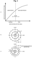
- Fig. 3 is a diagram illustrating an amplification characteristic of the amplification unit 23.
- Fig. 3(a) is a graph illustrating an input-output characteristic (amplification characteristic) of the amplification unit 23.
- Fig. 3(b) is a diagram illustrating a constellation of a transmission signal before being amplified by the amplification unit 23.
- Fig. 3(c) is a diagram illustrating a constellation of a transmission signal after being amplified by the amplification unit 23 by also using the non-linear region.
- Fig. 3(c) in a case where the amplification unit 23 amplifies the transmission signal by also using the non-linear region, distortion (amplitude decrease) occurs in the constellation.
- Fig. 3(c) illustrates a case where signal points of the first inner circumference and the second inner circumference are amplified in the linear region of the amplification unit 23, and signal points of the outermost circumference are amplified in the non-linear region of the amplification unit 23.
- Fig. 4 is a graph more specifically illustrating the input-output characteristic of the amplification unit 23.
- A is an input-output characteristic of an ideal amplifier capable of linear amplification from a small input power to a large input power.
- B illustrates the input-output characteristic of the amplification unit 23.
- C is a graph illustrating phase transition of the amplification unit 23.
- Fig. 5 is a diagram illustrating a phase transition countermeasure for the amplification unit 23 in a conventional technique.
- Fig. 5(a) is a diagram illustrating a phase transition countermeasure in 16 amplitude and phase shift keying (APSK).
- Fig. 5(b) is a diagram illustrating a phase transition countermeasure in 32 APSK.
- first inner circumference A2, second inner circumference B2, outermost circumference C2 including IQ coordinates of three ideal signal points having different radii (amplitudes)
- one or more ideal signal points P are transmitted as pilot signals with respect to each of amplitude levels of the first inner circumference A2 and the second inner circumference B2, whereby phase transition is compensated.
- Fig. 6 is a functional block diagram illustrating functions of the transmission device 2 according to the embodiment. Note that, in the transmission device 2 illustrated in Fig. 6 , components substantially the same as those of the transmission device 2a illustrated in Fig. 2 are denoted by the same reference signs.
- the training signal generation unit 26 generates three training signals for the constellation illustrated in Fig. 3 , for example.
- the training signals illustrated in Figs. 7(a) to 7(c) are some of signal points of a case where it is assumed that, for example, an input-output characteristic in the non-linear region of the amplification unit 23 is also linear.
- the number of signal points included in the training signal can be reduced by selecting a signal point representing a plurality of signal points.
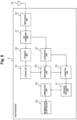
- Fig. 9 is a functional block diagram illustrating functions of the reception device 4 according to the embodiment.
- the reception device 4 according to the embodiment includes an amplification unit 40, an A/D conversion unit 41, an estimation unit 42, a storage unit 43, an equalization unit 44, an identification unit 45, a correction unit 46, a likelihood calculation unit 47, a demodulation unit 48, an information bit detection unit 49, and an antenna 50.
- the A/D conversion unit 41 converts the analog signal amplified by the amplification unit 40 into a digital signal and outputs the digital signal to the estimation unit 42 and the equalization unit 44.
- the A/D conversion unit 41 converts a training signal including the characteristic information indicating the input-output characteristic of the amplification unit 23 included in the transmission device 2 into a digital signal and outputs the digital signal to the estimation unit 42.
- the A/D conversion unit 41 converts a data signal corresponding to information bits to be transmitted from the transmission device 2 to the reception device 4 into a digital signal and outputs the digital signal to the equalization unit 44.
Landscapes
- Engineering & Computer Science (AREA)
- Computer Networks & Wireless Communication (AREA)
- Signal Processing (AREA)
- Power Engineering (AREA)
- Physics & Mathematics (AREA)
- Spectroscopy & Molecular Physics (AREA)
- Cable Transmission Systems, Equalization Of Radio And Reduction Of Echo (AREA)
- Digital Transmission Methods That Use Modulated Carrier Waves (AREA)
Abstract
Description
- The present invention relates to a wireless communication system, a wireless communication method, and a reception device.
- Conventionally, in a wireless communication system that performs single-carrier multi-level modulation, it is common to estimate a communication path by using a known signal such as binary phase-shift keying (BPSK) and perform demodulation by performing inverse calculation on a complex value of the estimation result.
- In addition, in a case where a transmission device transmits a signal by using a non-linear region of an amplifier, it is known that a phase transition countermeasure is performed by using a plurality of pilot signals on concentric circles (see, for example, Patent Literature 1).
- However, in a case where non-linearity exists in an amplification characteristic of the amplifier included in the transmission device, it has been necessary to correct a signal point having a large amplitude to a value having an amplitude smaller than a communication path estimated value of a case where the signal point is amplified with a linear amplification characteristic (see, for example, Non Patent Literature 1).
- Patent Literature 1:
JP 2017-59889 A - Non Patent Literature 1: MOHAMED IBNKAHLA, et al., "High-Speed Satellite Mobile Communications: Technologies and Challenges", PROCEEDINGS OF THE IEEE, VOL. 92, NO. 2, FEBRUARY 2004, p.312-339
- The present invention has been made in view of the problem described above, and an object thereof is to provide a wireless communication system, a wireless communication method, and a reception device capable of accurately demodulating a signal even when a transmission device that performs single-carrier multi-level modulation transmits a signal amplified by using a non-linear region.
- A wireless communication system according to an aspect of the present invention is a wireless communication system in which a reception device demodulates a signal on the basis of a training signal transmitted by a transmission device that performs single-carrier multi-level modulation, in which the transmission device transmits the training signal to the reception device such that a plurality of signal points having different amplitudes on a constellation is included, and the reception device includes: an estimation unit that estimates the signal points included in the training signal of a case where it is assumed that, on the basis of characteristic information indicating an input-output characteristic including a non-linear region of an amplification unit that is provided in the transmission device and amplifies a signal to be transmitted, an input-output characteristic in a non-linear region of the amplification unit is also linear; an equalization unit that performs initial equalization on a received signal; a correction unit that corrects a signal subjected to initial equalization by the equalization unit on the basis of the signal points estimated by the estimation unit; a likelihood calculation unit that calculates, with respect to a constellation before the amplification unit amplifies a signal, a likelihood of a signal corrected by the correction unit; and a demodulation unit that demodulates a signal on the basis of the likelihood calculated by the likelihood calculation unit.
- In addition, a wireless communication method according to an aspect of the present invention is a wireless communication method in which a reception device demodulates a signal on the basis of a training signal transmitted by a transmission device that performs single-carrier multi-level modulation, the wireless communication method including: a transmission step in which the transmission device transmits the training signal to the reception device such that a plurality of signal points having different amplitudes on a constellation is included; an estimation step in which the reception device estimates the signal points included in the training signal of a case where it is assumed that, on the basis of characteristic information indicating an input-output characteristic including a non-linear region of an amplification unit that is provided in the transmission device and amplifies a signal to be transmitted, an input-output characteristic in a non-linear region of the amplification unit is also linear; an equalization step in which the reception device performs initial equalization on a received signal; a correction step in which the reception device corrects a signal subjected to initial equalization by the equalization step on the basis of the signal points estimated by the estimation step; a likelihood calculation step in which the reception device calculates, with respect to a constellation before the amplification unit amplifies a signal, a likelihood of a signal corrected by the correction step; and a demodulation step in which the reception device demodulates a signal on the basis of the likelihood calculated by the likelihood calculation step.
- In addition, a reception device according to an aspect of the present invention is a reception device that demodulates a signal on the basis of a training signal transmitted by a transmission device that performs single-carrier multi-level modulation, the reception device including: an estimation unit that estimates a plurality of signal points included in the training signal transmitted by the transmission device such that the plurality of signal points having different amplitudes on a constellation is included on an assumption that, on the basis of characteristic information indicating an input-output characteristic including a non-linear region of an amplification unit that is provided in the transmission device and amplifies a signal to be transmitted, an input-output characteristic in a non-linear region of the amplification unit is also linear; an equalization unit that performs initial equalization on a received signal; a correction unit that corrects a signal subjected to initial equalization by the equalization unit on the basis of the signal points estimated by the estimation unit; a likelihood calculation unit that calculates, with respect to a constellation before the amplification unit amplifies a signal, a likelihood of a signal corrected by the correction unit; and a demodulation unit that demodulates a signal on the basis of the likelihood calculated by the likelihood calculation unit.
- According to the present invention, even when a transmission device that performs single-carrier multi-level modulation transmits a signal amplified by using a non-linear region, it is possible to accurately demodulate the signal.
-
-
Fig. 1 is a diagram illustrating a configuration example of a wireless communication system according to an embodiment. -
Fig. 2 is a functional block diagram illustrating functions of a transmission device of a comparative example. -
Fig. 3(a) is a graph illustrating an input-output characteristic of an amplification unit.Fig. 3(b) is a diagram illustrating a constellation of a transmission signal before being amplified by the amplification unit.Fig. 3(c) is a diagram illustrating a constellation of a transmission signal after being amplified by the amplification unit by also using a non-linear region. -
Fig. 4 is a graph more specifically illustrating the input-output characteristic of the amplification unit. -
Fig. 5(a) is a diagram illustrating a phase transition countermeasure in 16 APSK.Fig. 5(b) is a diagram illustrating a phase transition countermeasure in 32 APSK. -
Fig. 6 is a functional block diagram illustrating functions of a transmission device according to the embodiment. -
Fig. 7(a) is a diagram illustrating a first training signal for a first inner circumference generated by a training signal generation unit.Fig. 7(b) is a diagram illustrating a second training signal for a second inner circumference generated by the training signal generation unit.Fig. 7(c) is a diagram illustrating a third training signal for an outermost circumference generated by the training signal generation unit. -
Fig. 8 is a diagram illustrating another example of a training signal generated by the training signal generation unit. -
Fig. 9 is a functional block diagram illustrating functions of a reception device according to the embodiment. -
Fig. 10(a) is a diagram illustrating signal points subjected to initial equalization by an equalization unit.Fig. 10(b) is a diagram illustrating a third communication path estimated value identified by an identification unit.Fig. 10(c) is a diagram illustrating a constellation corrected by a correction unit. - Hereinafter, an embodiment of a wireless communication system will be described with reference to the drawings.
Fig. 1 is a diagram illustrating a configuration example of awireless communication system 1 according to the embodiment. Thewireless communication system 1 is configured such that, for example, a transmission device 2 that performs single-carrier multi-level modulation transmits a signal amplified by using a non-linear region, and a reception device 4 receives and demodulates the signal. - In addition, the transmission device 2 transmits a training signal for calculating communication path information (for example, channel state information (CSI)) to the reception device 4. The reception device 4 calculates the communication path information by using the received training signal, and transmits the calculated communication path information to the transmission device 2.
- Note that, regarding the communication path information, there is a case where the transmission device 2 is known and a case where the transmission device 2 is unknown. In addition, the transmission device 2 and the reception device 4 may have the same function so that each perform transmission and reception.
- Here, to help understanding of the configuration of the
wireless communication system 1 according to the embodiment, first, a configuration example of atransmission device 2a of a comparative example will be described.Fig. 2 is a functional block diagram illustrating functions of thetransmission device 2a of the comparative example. - As illustrated in
Fig. 2 , thetransmission device 2a of the comparative example includes an informationbit generation unit 20, amodulation unit 21, a D/A conversion unit 22, anamplification unit 23, and anantenna 24. - The information
bit generation unit 20 generates information bits to be transmitted to the reception device 4, and outputs the information bits to themodulation unit 21. In addition, the informationbit generation unit 20 may have an error correction coding function and an interleaving function. - The
modulation unit 21 modulates the information bits generated by the informationbit generation unit 20 into a data signal by, for example, a single-carrier multi-level modulation scheme, and outputs the data signal to the D/A conversion unit 22. Examples of the single-carrier multi-level modulation scheme performed by themodulation unit 21 include quadrature amplitude modulation (64 QAM, 256 QAM). - The D/
A conversion unit 22 converts the data signal digitally modulated by themodulation unit 21 into an analog signal and outputs the analog signal to theamplification unit 23. - The
amplification unit 23 amplifies the analog signal converted by the D/A conversion unit 22 and emits the amplified signal via theantenna 24. -
Fig. 3 is a diagram illustrating an amplification characteristic of theamplification unit 23.Fig. 3(a) is a graph illustrating an input-output characteristic (amplification characteristic) of theamplification unit 23.Fig. 3(b) is a diagram illustrating a constellation of a transmission signal before being amplified by theamplification unit 23.Fig. 3(c) is a diagram illustrating a constellation of a transmission signal after being amplified by theamplification unit 23 by also using the non-linear region. - As illustrated in
Fig. 3(a) , theamplification unit 23 has a linear region in which amplification is performed in proportion to an input and output is performed, and a non-linear region in which amplification is performed non-linearly for an excessive input. - As illustrated in
Fig. 3(b) , no distortion occurs in the constellation of the transmission signal before being amplified by theamplification unit 23. In addition, also in a case where theamplification unit 23 amplifies the transmission signal by using only the linear region, similarly, no distortion occurs in the constellation of the transmission signal. Note that, inFig. 3 , a first inner circumference of the constellation is denoted by A, a second inner circumference is denoted by B, and an outermost circumference is denoted by C. - On the other hand, as illustrated in
Fig. 3(c) , in a case where theamplification unit 23 amplifies the transmission signal by also using the non-linear region, distortion (amplitude decrease) occurs in the constellation. Note thatFig. 3(c) illustrates a case where signal points of the first inner circumference and the second inner circumference are amplified in the linear region of theamplification unit 23, and signal points of the outermost circumference are amplified in the non-linear region of theamplification unit 23. -
Fig. 4 is a graph more specifically illustrating the input-output characteristic of theamplification unit 23. InFig. 4 , A is an input-output characteristic of an ideal amplifier capable of linear amplification from a small input power to a large input power. B illustrates the input-output characteristic of theamplification unit 23. C is a graph illustrating phase transition of theamplification unit 23. -
Fig. 5 is a diagram illustrating a phase transition countermeasure for theamplification unit 23 in a conventional technique.Fig. 5(a) is a diagram illustrating a phase transition countermeasure in 16 amplitude and phase shift keying (APSK).Fig. 5(b) is a diagram illustrating a phase transition countermeasure in 32 APSK. - As illustrated in
Fig. 5(a) , conventionally, in a constellation (inner circumference A1 and outermost circumference B1) including IQ coordinates of two ideal signal points having different radii (amplitudes), one or more ideal signal points P are transmitted as pilot signals (known signals) with respect to an amplitude level of the inner circumference A1, whereby phase transition is compensated. - In addition, as illustrated in
Fig. 5(b) , conventionally, in a constellation (first inner circumference A2, second inner circumference B2, outermost circumference C2) including IQ coordinates of three ideal signal points having different radii (amplitudes), one or more ideal signal points P are transmitted as pilot signals with respect to each of amplitude levels of the first inner circumference A2 and the second inner circumference B2, whereby phase transition is compensated. - As described above, conventionally, to compensate for phase characteristics different for respective amplitudes of the constellation, one pilot signal is arranged for each of signal points having different radii, whereby the reception device is enabled to compensate for the phase transition of the signal points and perform demodulation.
- In the single-carrier multi-level modulation scheme, it is expected to improve an SNR by increasing average transmission power to an allowable value. On the other hand, when excessive transmission power is input to the
amplification unit 23, an amplitude of a peak signal or the like decreases due to saturation. Then, when equalization is performed with a communication path response estimated by a training signal (for example, BPSK) in the linear region, a detection error occurs in the peak signal or the like. For that reason, in general, communication is performed with sufficiently low transmission power (small amplitude) at which no distortion occurs in the peak signal. - As described above, conventionally, even if an amplitude of a signal point transitions due to the input-output characteristic of the amplifier, the signal point cannot be compensated, and demodulation cannot be performed accurately in some cases.
- Thus, the
wireless communication system 1 according to the embodiment is configured such that, the transmission device 2 transmits a training signal to the reception device 4 such that a plurality of signal points having different amplitudes on a constellation is included, and the reception device 4 performs demodulation on the basis of the training signal, whereby demodulation can be accurately performed. -
Fig. 6 is a functional block diagram illustrating functions of the transmission device 2 according to the embodiment. Note that, in the transmission device 2 illustrated inFig. 6 , components substantially the same as those of thetransmission device 2a illustrated inFig. 2 are denoted by the same reference signs. - As illustrated in
Fig. 6 , the transmission device 2 according to the embodiment includes the informationbit generation unit 20, themodulation unit 21, the D/A conversion unit 22, theamplification unit 23, theantenna 24, a characteristicdata generation unit 25, and a trainingsignal generation unit 26. - The characteristic
data generation unit 25 converts the input-output characteristic of theamplification unit 23 into data, generates characteristic information indicating the input-output characteristic of theamplification unit 23, and outputs the characteristic information to the informationbit generation unit 20. - Thus, the information
bit generation unit 20 includes the characteristic information indicating the input-output characteristic of theamplification unit 23 in information bits to be generated. - The training
signal generation unit 26 generates training signals of a plurality of radius (amplitude) patterns depending on the constellation, and adds the training signals to a signal output by themodulation unit 21 to the D/A conversion unit 22. -
Fig. 7 is a diagram illustrating training signals generated by the trainingsignal generation unit 26 for the constellation illustrated inFig. 3 , for example.Fig. 7(a) is a diagram illustrating a first training signal for the first inner circumference A generated by the trainingsignal generation unit 26.Fig. 7(b) is a diagram illustrating a second training signal for the second inner circumference B generated by the trainingsignal generation unit 26.Fig. 7(c) is a diagram illustrating a third training signal for the outermost circumference C generated by the trainingsignal generation unit 26. - As illustrated in
Figs. 7(a) to 7(c) , the trainingsignal generation unit 26 generates three training signals for the constellation illustrated inFig. 3 , for example. Here, the training signals illustrated inFigs. 7(a) to 7(c) are some of signal points of a case where it is assumed that, for example, an input-output characteristic in the non-linear region of theamplification unit 23 is also linear. - As described above, the training signals include a plurality of signal points having different amplitudes on the constellation before the
amplification unit 23 amplifies the signal. - Then, the three training signals illustrated in
Figs. 7(a) to 7(c) are transmitted to the reception device 4, and are used for calculation of a signal considered to be amplified by an ideal amplifier capable of linear amplification from a small input power to a large input power. -
Fig. 8 is a diagram illustrating another example of the training signal generated by the trainingsignal generation unit 26. As illustrated inFig. 8 , the training signal generated by the trainingsignal generation unit 26 may be a training signal including one signal point selected for each of regions on a constellation determined in advance including a plurality of signal points. - That is, for a constellation having many signal points, the number of signal points included in the training signal can be reduced by selecting a signal point representing a plurality of signal points.
-
Fig. 9 is a functional block diagram illustrating functions of the reception device 4 according to the embodiment. As illustrated inFig. 9 , the reception device 4 according to the embodiment includes anamplification unit 40, an A/D conversion unit 41, anestimation unit 42, astorage unit 43, anequalization unit 44, anidentification unit 45, acorrection unit 46, alikelihood calculation unit 47, ademodulation unit 48, an informationbit detection unit 49, and anantenna 50. - The
amplification unit 40 amplifies an analog signal received by the reception device 4 via theantenna 50 and outputs the amplified analog signal to the A/D conversion unit 41. - The A/
D conversion unit 41 converts the analog signal amplified by theamplification unit 40 into a digital signal and outputs the digital signal to theestimation unit 42 and theequalization unit 44. For example, the A/D conversion unit 41 converts a training signal including the characteristic information indicating the input-output characteristic of theamplification unit 23 included in the transmission device 2 into a digital signal and outputs the digital signal to theestimation unit 42. In addition, the A/D conversion unit 41 converts a data signal corresponding to information bits to be transmitted from the transmission device 2 to the reception device 4 into a digital signal and outputs the digital signal to theequalization unit 44. - Note that the training signal converted into the digital signal by the A/
D conversion unit 41 is transmitted when the transmission device 2 and the reception device 4 start communication. - The
estimation unit 42 estimates a communication path on the basis of the training signal input from the A/D conversion unit 41 (for example, a first communication path estimated value to a third communication path estimated value illustrated inFig. 7 ). That is, theestimation unit 42 estimates signal points included in the training signal of a case where it is assumed that the input-output characteristic in the non-linear region of theamplification unit 23 is also linear, on the basis of the characteristic information indicating the input-output characteristic including the non-linear region of theamplification unit 23 provided in the transmission device 2 to amplify a signal to be transmitted. - The
storage unit 43 stores the communication path estimated by theestimation unit 42, and outputs the communication path according to an accelerator from theidentification unit 45. That is, the reception device 4 can share the characteristic information indicating the input-output characteristic of theamplification unit 23 with the transmission device 2. - The
equalization unit 44 performs initial equalization on the data signal input from the A/D conversion unit 41, and outputs the data signal to theidentification unit 45 and thecorrection unit 46. - The
identification unit 45 identifies a signal value that needs correction in the data signal subjected to initial equalization by theequalization unit 44 on the basis of the communication path (for example, the first communication path estimated value to the third communication path estimated value illustrated inFig. 7 ) stored in thestorage unit 43, and outputs the signal value to thecorrection unit 46. - The
correction unit 46 corrects the signal value subjected to initial equalization by theequalization unit 44 on the basis of the signal value identified by theidentification unit 45, and outputs a signal including the corrected constellation to thelikelihood calculation unit 47. For example, thecorrection unit 46 performs correction by multiplying the signal value subjected to initial equalization by theequalization unit 44 by a ratio between the non-linear input-output characteristic and the linear input-output characteristic. -
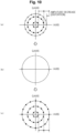
Fig. 10 is a diagram illustrating a processing process in which thecorrection unit 46 corrects the signal values subjected to initial equalization by theequalization unit 44.Fig. 10(a) is a diagram illustrating signal points subjected to initial equalization by theequalization unit 44.Fig. 10(b) is a diagram illustrating the third communication path estimated value identified by theidentification unit 45.Fig. 10(c) is a diagram illustrating a constellation corrected by thecorrection unit 46. - As illustrated in
Fig. 10 , thecorrection unit 46 outputs the corrected constellation (c) to thelikelihood calculation unit 47 on the basis of the signal point (b) included in the training signal of a case where it is assumed that the input-output characteristic in the non-linear region of theamplification unit 23 is also be linear with respect to the constellation (a) distorted due to the input-output characteristic of theamplification unit 23. - The
likelihood calculation unit 47 calculates a likelihood of the signal corrected by thecorrection unit 46 with respect to the constellation before theamplification unit 23 of the transmission device 2 amplifies the signal, and outputs the calculated likelihood to thedemodulation unit 48. - The
demodulation unit 48 demodulates the signal on the basis of the likelihood calculated by thelikelihood calculation unit 47, and outputs the demodulated signal to the informationbit detection unit 49. - The information
bit detection unit 49 detects information bits from the signal demodulated by thedemodulation unit 48. Thus, since the reception device 4 according to the embodiment corrects the signal subjected to initial equalization by theequalization unit 44 and demodulates the signal on the basis of the likelihood calculated by thelikelihood calculation unit 47, the signal can be accurately demodulated even if the transmission device 2 that performs single-carrier multi-level modulation transmits the signal amplified by using the non-linear region. - As described above, the reception device 4 can perform likelihood calculation based on a non-distortion constellation before a Euclidean distance between signal points is narrowed, and can accurately demodulate the signal.
- Note that, some or all of the units constituting the transmission device 2 and the reception device 4 in the embodiment described above may be configured by hardware, or may be configured by causing a processor to execute a program.
- In addition, in a case where some or all of the units constituting the transmission device 2 and the reception device 4 are configured by causing a processor to execute a program, the program may be recorded in a recording medium and supplied, or may be supplied via a network.
-
- 1
- Wireless communication system
- 2, 2a
- Transmission device
- 4
- Reception device
- 20
- Information bit generation unit
- 21
- Modulation unit
- 22
- D/A conversion unit
- 23
- Amplification unit
- 24
- Antenna
- 25
- Characteristic data generation unit
- 26
- Training signal generation unit
- 40
- Amplification unit
- 41
- A/D conversion unit
- 42
- Estimation unit
- 43
- Storage unit
- 44
- Equalization unit
- 45
- Identification unit
- 46
- Correction unit
- 47
- Likelihood calculation unit
- 48
- Demodulation unit
- 49
- Information bit detection unit
- 50
- Antenna
Claims (8)
- A wireless communication system in which a reception device demodulates a signal on a basis of a training signal transmitted by a transmission device that performs single-carrier multi-level modulation,
whereinthe transmission devicetransmits the training signal to the reception device such that a plurality of signal points having different amplitudes on a constellation is included, andthe reception device includes:an estimation unit that estimates the signal points included in the training signal of a case where it is assumed that, on a basis of characteristic information indicating an input-output characteristic including a non-linear region of an amplification unit that is provided in the transmission device and amplifies a signal to be transmitted, an input-output characteristic in a non-linear region of the amplification unit is also linear;an equalization unit that performs initial equalization on a received signal;a correction unit that corrects a signal subjected to initial equalization by the equalization unit on a basis of the signal points estimated by the estimation unit;a likelihood calculation unit that calculates, with respect to a constellation before the amplification unit amplifies a signal, a likelihood of a signal corrected by the correction unit; anda demodulation unit that demodulates a signal on a basis of the likelihood calculated by the likelihood calculation unit. - The wireless communication system according to claim 1, whereinthe reception devicereceives the characteristic information from the transmission device.
- The wireless communication system according to claim 1 or 2, whereinthe training signal includesa plurality of signal points having different amplitudes on the constellation before the amplification unit amplifies the signal.
- The wireless communication system according to any one of claims 1 to 3, whereinthe training signalincludes one signal point selected for each of regions on a predetermined constellation including a plurality of signal points.
- A wireless communication method in which a reception device demodulates a signal on a basis of a training signal transmitted by a transmission device that performs single-carrier multi-level modulation,
the wireless communication method comprising:a transmission step in which the transmission device transmits the training signal to the reception device such that a plurality of signal points having different amplitudes on a constellation is included;an estimation step in which the reception device estimates the signal points included in the training signal of a case where it is assumed that, on a basis of characteristic information indicating an input-output characteristic including a non-linear region of an amplification unit that is provided in the transmission device and amplifies a signal to be transmitted, an input-output characteristic in a non-linear region of the amplification unit is also linear;an equalization step in which the reception device performs initial equalization on a received signal;a correction step in which the reception device corrects a signal subjected to initial equalization by the equalization step on a basis of the signal points estimated by the estimation step;a likelihood calculation step in which the reception device calculates, with respect to a constellation before the amplification unit amplifies a signal, a likelihood of a signal corrected by the correction step; anda demodulation step in which the reception device demodulates a signal on a basis of the likelihood calculated by the likelihood calculation step. - A reception device that demodulates a signal on a basis of a training signal transmitted by a transmission device that performs single-carrier multi-level modulation,
the reception device comprising:an estimation unit that estimates a plurality of signal points included in the training signal transmitted by the transmission device such that the plurality of signal points having different amplitudes on a constellation is included on an assumption that, on a basis of characteristic information indicating an input-output characteristic including a non-linear region of an amplification unit that is provided in the transmission device and amplifies a signal to be transmitted, an input-output characteristic in a non-linear region of the amplification unit is also linear;an equalization unit that performs initial equalization on a received signal;a correction unit that corrects a signal subjected to initial equalization by the equalization unit on a basis of the signal points estimated by the estimation unit;a likelihood calculation unit that calculates, with respect to a constellation before the amplification unit amplifies a signal, a likelihood of a signal corrected by the correction unit; anda demodulation unit that demodulates a signal on a basis of the likelihood calculated by the likelihood calculation unit. - The reception device according to claim 6, whereinthe estimation unitestimates the signal points on a basis of the characteristic information transmitted by the transmission device.
- The reception device according to claim 6 or 7, whereinthe training signal includesa plurality of signal points having different amplitudes on the constellation before the amplification unit amplifies the signal.
Applications Claiming Priority (1)
| Application Number | Priority Date | Filing Date | Title |
|---|---|---|---|
| PCT/JP2021/032437 WO2023032153A1 (en) | 2021-09-03 | 2021-09-03 | Wireless communication system, wireless communication method, and receiver device |
Publications (3)
| Publication Number | Publication Date |
|---|---|
| EP4398529A1 true EP4398529A1 (en) | 2024-07-10 |
| EP4398529A4 EP4398529A4 (en) | 2025-06-11 |
| EP4398529B1 EP4398529B1 (en) | 2026-03-11 |
Family
ID=85412372
Family Applications (1)
| Application Number | Title | Priority Date | Filing Date |
|---|---|---|---|
| EP21956041.4A Active EP4398529B1 (en) | 2021-09-03 | 2021-09-03 | Wireless communication system, wireless communication method, and receiver device |
Country Status (4)
| Country | Link |
|---|---|
| US (1) | US12489660B2 (en) |
| EP (1) | EP4398529B1 (en) |
| JP (1) | JP7643565B2 (en) |
| WO (1) | WO2023032153A1 (en) |
Families Citing this family (1)
| Publication number | Priority date | Publication date | Assignee | Title |
|---|---|---|---|---|
| US20250155538A1 (en) * | 2022-02-24 | 2025-05-15 | Nippon Telegraph And Telephone Corporation | Radio wave arrival direction estimation device and radio wave arrival direction estimation method |
Family Cites Families (10)
| Publication number | Priority date | Publication date | Assignee | Title |
|---|---|---|---|---|
| JP5053302B2 (en) | 2009-01-26 | 2012-10-17 | 日本放送協会 | Digital transmission decoder and receiver |
| JP5232677B2 (en) | 2009-02-02 | 2013-07-10 | 日本放送協会 | Digital transmission decoder and receiver |
| US8566687B1 (en) * | 2012-06-20 | 2013-10-22 | MagnaCom Ltd. | Method and system for forward error correction decoding with parity check for use in low complexity highly-spectrally efficient communications |
| JP2015002354A (en) | 2013-06-12 | 2015-01-05 | ソニー株式会社 | Transmitting apparatus, signal transmitting method for transmitting apparatus, receiving apparatus, signal receiving method for receiving apparatus, and program |
| JP6323753B2 (en) * | 2013-06-14 | 2018-05-16 | サン パテント トラスト | Sending method |
| WO2015033232A2 (en) * | 2013-09-09 | 2015-03-12 | MagnaCom Ltd. | Adaptive nonlinear model learning |
| JP6577800B2 (en) | 2015-09-14 | 2019-09-18 | 日本放送協会 | Single carrier transmission device and reception device |
| JP6924606B2 (en) | 2017-04-21 | 2021-08-25 | 日本放送協会 | Single carrier type transmitter |
| EP3499823B1 (en) | 2017-12-18 | 2020-09-16 | Mitsubishi Electric R & D Centre Europe B.V. | Method and device for demodulating received symbols using a turbo equalization loop for a single carrier system |
| JP7316099B2 (en) | 2019-05-25 | 2023-07-27 | 日本放送協会 | Apparatus and program for detecting optimum value of single-carrier method parameters |
-
2021
- 2021-09-03 JP JP2023544935A patent/JP7643565B2/en active Active
- 2021-09-03 US US18/681,087 patent/US12489660B2/en active Active
- 2021-09-03 WO PCT/JP2021/032437 patent/WO2023032153A1/en not_active Ceased
- 2021-09-03 EP EP21956041.4A patent/EP4398529B1/en active Active
Also Published As
| Publication number | Publication date |
|---|---|
| WO2023032153A1 (en) | 2023-03-09 |
| US20240275649A1 (en) | 2024-08-15 |
| EP4398529B1 (en) | 2026-03-11 |
| JP7643565B2 (en) | 2025-03-11 |
| JPWO2023032153A1 (en) | 2023-03-09 |
| EP4398529A4 (en) | 2025-06-11 |
| US12489660B2 (en) | 2025-12-02 |
Similar Documents
| Publication | Publication Date | Title |
|---|---|---|
| US7971128B2 (en) | Soft decision correction method, receiver using the same, and program therefor | |
| JP6577800B2 (en) | Single carrier transmission device and reception device | |
| US7483497B2 (en) | Method and apparatus for calculating log-likelihood ratio for decoding in a receiver for a mobile communication system | |
| US6738430B2 (en) | Apparatus and method for digital wireless communications | |
| JPH08163198A (en) | Non-linear distortion compensator | |
| CN111064691B (en) | Transmitter, receiver and signal processing method | |
| EP4391469B1 (en) | Wireless communication system, wireless communication method, and reception apparatus | |
| EP4398533B1 (en) | Wireless communication system, wireless communication method, and wireless communication transmission device | |
| US8705665B2 (en) | Process for performing log-likelihood-ratio clipping in a soft-decision near-ML detector, and detector for doing the same | |
| EP4398529B1 (en) | Wireless communication system, wireless communication method, and receiver device | |
| EP1143611A1 (en) | Digital automatic gain control | |
| US12457144B2 (en) | Wireless communication system, wireless communication method, centralized control device, and wireless communication program | |
| US20250158857A1 (en) | Wireless communication method, wireless communication system, and transmission device | |
| JPH10210093A (en) | Signal offset removal method | |
| US20250112808A1 (en) | Wireless communication method, wireless communication system, and transmission device | |
| EP4398528A1 (en) | Wireless communication system, wireless communication method, and wireless communication transmission device | |
| US20060008019A1 (en) | Communications method | |
| JP2861778B2 (en) | Demodulator | |
| WO2024171447A1 (en) | Wireless communication system, reception device, wireless communication method, and reception program | |
| JP2007110386A (en) | Wireless communication method, and modulator and demodulator | |
| JP2002247120A (en) | Wireless signal receiver |
Legal Events
| Date | Code | Title | Description |
|---|---|---|---|
| STAA | Information on the status of an ep patent application or granted ep patent |
Free format text: STATUS: THE INTERNATIONAL PUBLICATION HAS BEEN MADE |
|
| PUAI | Public reference made under article 153(3) epc to a published international application that has entered the european phase |
Free format text: ORIGINAL CODE: 0009012 |
|
| STAA | Information on the status of an ep patent application or granted ep patent |
Free format text: STATUS: REQUEST FOR EXAMINATION WAS MADE |
|
| 17P | Request for examination filed |
Effective date: 20240202 |
|
| AK | Designated contracting states |
Kind code of ref document: A1 Designated state(s): AL AT BE BG CH CY CZ DE DK EE ES FI FR GB GR HR HU IE IS IT LI LT LU LV MC MK MT NL NO PL PT RO RS SE SI SK SM TR |
|
| DAV | Request for validation of the european patent (deleted) | ||
| DAX | Request for extension of the european patent (deleted) | ||
| REG | Reference to a national code |
Ref legal event code: R079 Ipc: H04B0001120000 Ref country code: DE Ref legal event code: R079 Ref document number: 602021049984 Country of ref document: DE Free format text: PREVIOUS MAIN CLASS: H04L0027260000 Ipc: H04B0001120000 |
|
| A4 | Supplementary search report drawn up and despatched |
Effective date: 20250512 |
|
| RIC1 | Information provided on ipc code assigned before grant |
Ipc: H04B 1/12 20060101AFI20250506BHEP |
|
| RAP3 | Party data changed (applicant data changed or rights of an application transferred) |
Owner name: NTT, INC. |
|
| GRAP | Despatch of communication of intention to grant a patent |
Free format text: ORIGINAL CODE: EPIDOSNIGR1 |
|
| STAA | Information on the status of an ep patent application or granted ep patent |
Free format text: STATUS: GRANT OF PATENT IS INTENDED |
|
| RIC1 | Information provided on ipc code assigned before grant |
Ipc: H04B 1/12 20060101AFI20251028BHEP |
|
| INTG | Intention to grant announced |
Effective date: 20251128 |
|
| GRAS | Grant fee paid |
Free format text: ORIGINAL CODE: EPIDOSNIGR3 |
|
| GRAA | (expected) grant |
Free format text: ORIGINAL CODE: 0009210 |
|
| STAA | Information on the status of an ep patent application or granted ep patent |
Free format text: STATUS: THE PATENT HAS BEEN GRANTED |
|
| AK | Designated contracting states |
Kind code of ref document: B1 Designated state(s): AL AT BE BG CH CY CZ DE DK EE ES FI FR GB GR HR HU IE IS IT LI LT LU LV MC MK MT NL NO PL PT RO RS SE SI SK SM TR |
|
| REG | Reference to a national code |
Ref country code: CH Ref legal event code: F10 Free format text: ST27 STATUS EVENT CODE: U-0-0-F10-F00 (AS PROVIDED BY THE NATIONAL OFFICE) Effective date: 20260311 Ref country code: GB Ref legal event code: FG4D |
|
| REG | Reference to a national code |
Ref country code: DE Ref legal event code: R096 Ref document number: 602021049984 Country of ref document: DE |
|
| REG | Reference to a national code |
Ref country code: IE Ref legal event code: FG4D |
|
| PG25 | Lapsed in a contracting state [announced via postgrant information from national office to epo] |
Ref country code: RS Free format text: LAPSE BECAUSE OF FAILURE TO SUBMIT A TRANSLATION OF THE DESCRIPTION OR TO PAY THE FEE WITHIN THE PRESCRIBED TIME-LIMIT Effective date: 20260611 |
|
| PG25 | Lapsed in a contracting state [announced via postgrant information from national office to epo] |
Ref country code: ES Free format text: LAPSE BECAUSE OF FAILURE TO SUBMIT A TRANSLATION OF THE DESCRIPTION OR TO PAY THE FEE WITHIN THE PRESCRIBED TIME-LIMIT Effective date: 20260311 |
|
| PG25 | Lapsed in a contracting state [announced via postgrant information from national office to epo] |
Ref country code: GR Free format text: LAPSE BECAUSE OF FAILURE TO SUBMIT A TRANSLATION OF THE DESCRIPTION OR TO PAY THE FEE WITHIN THE PRESCRIBED TIME-LIMIT Effective date: 20260612 |
|
| REG | Reference to a national code |
Ref country code: LT Ref legal event code: MG9D |
|
| PG25 | Lapsed in a contracting state [announced via postgrant information from national office to epo] |
Ref country code: LT Free format text: LAPSE BECAUSE OF FAILURE TO SUBMIT A TRANSLATION OF THE DESCRIPTION OR TO PAY THE FEE WITHIN THE PRESCRIBED TIME-LIMIT Effective date: 20260311 |
|
| PG25 | Lapsed in a contracting state [announced via postgrant information from national office to epo] |
Ref country code: NO Free format text: LAPSE BECAUSE OF FAILURE TO SUBMIT A TRANSLATION OF THE DESCRIPTION OR TO PAY THE FEE WITHIN THE PRESCRIBED TIME-LIMIT Effective date: 20260611 |
|
| PG25 | Lapsed in a contracting state [announced via postgrant information from national office to epo] |
Ref country code: SE Free format text: LAPSE BECAUSE OF FAILURE TO SUBMIT A TRANSLATION OF THE DESCRIPTION OR TO PAY THE FEE WITHIN THE PRESCRIBED TIME-LIMIT Effective date: 20260311 Ref country code: FI Free format text: LAPSE BECAUSE OF FAILURE TO SUBMIT A TRANSLATION OF THE DESCRIPTION OR TO PAY THE FEE WITHIN THE PRESCRIBED TIME-LIMIT Effective date: 20260311 |
|
| REG | Reference to a national code |
Ref country code: NL Ref legal event code: MP Effective date: 20260311 |
|
| PG25 | Lapsed in a contracting state [announced via postgrant information from national office to epo] |
Ref country code: HR Free format text: LAPSE BECAUSE OF FAILURE TO SUBMIT A TRANSLATION OF THE DESCRIPTION OR TO PAY THE FEE WITHIN THE PRESCRIBED TIME-LIMIT Effective date: 20260311 |
|
| PG25 | Lapsed in a contracting state [announced via postgrant information from national office to epo] |
Ref country code: LV Free format text: LAPSE BECAUSE OF FAILURE TO SUBMIT A TRANSLATION OF THE DESCRIPTION OR TO PAY THE FEE WITHIN THE PRESCRIBED TIME-LIMIT Effective date: 20260311 |
|
| PG25 | Lapsed in a contracting state [announced via postgrant information from national office to epo] |
Ref country code: BG Free format text: LAPSE BECAUSE OF FAILURE TO SUBMIT A TRANSLATION OF THE DESCRIPTION OR TO PAY THE FEE WITHIN THE PRESCRIBED TIME-LIMIT Effective date: 20260311 |