EP4398447A1 - Electronic device, and power control method based on plurality of batteries in electronic device - Google Patents
Electronic device, and power control method based on plurality of batteries in electronic device Download PDFInfo
- Publication number
- EP4398447A1 EP4398447A1 EP23801292.6A EP23801292A EP4398447A1 EP 4398447 A1 EP4398447 A1 EP 4398447A1 EP 23801292 A EP23801292 A EP 23801292A EP 4398447 A1 EP4398447 A1 EP 4398447A1
- Authority
- EP
- European Patent Office
- Prior art keywords
- battery
- electronic device
- overcurrent
- processor
- fuel gauge
- Prior art date
- Legal status (The legal status is an assumption and is not a legal conclusion. Google has not performed a legal analysis and makes no representation as to the accuracy of the status listed.)
- Pending
Links
Images




Classifications
-
- H—ELECTRICITY
- H02—GENERATION; CONVERSION OR DISTRIBUTION OF ELECTRIC POWER
- H02J—ELECTRIC POWER NETWORKS; CIRCUIT ARRANGEMENTS OR SYSTEMS FOR SUPPLYING OR DISTRIBUTING ELECTRIC POWER; SYSTEMS FOR STORING ELECTRIC ENERGY
- H02J7/00—Circuit arrangements for charging or discharging batteries or for supplying loads from batteries
- H02J7/90—Regulation of charging or discharging current or voltage
- H02J7/94—Regulation of charging or discharging current or voltage in response to battery current
-
- H—ELECTRICITY
- H01—ELECTRIC ELEMENTS
- H01M—PROCESSES OR MEANS, e.g. BATTERIES, FOR THE DIRECT CONVERSION OF CHEMICAL ENERGY INTO ELECTRICAL ENERGY
- H01M10/00—Secondary cells; Manufacture thereof
- H01M10/42—Methods or arrangements for servicing or maintenance of secondary cells or secondary half-cells
- H01M10/44—Methods for charging or discharging
-
- H—ELECTRICITY
- H01—ELECTRIC ELEMENTS
- H01M—PROCESSES OR MEANS, e.g. BATTERIES, FOR THE DIRECT CONVERSION OF CHEMICAL ENERGY INTO ELECTRICAL ENERGY
- H01M10/00—Secondary cells; Manufacture thereof
- H01M10/42—Methods or arrangements for servicing or maintenance of secondary cells or secondary half-cells
- H01M10/425—Structural combination with electronic components, e.g. electronic circuits integrated to the outside of the casing
-
- H—ELECTRICITY
- H01—ELECTRIC ELEMENTS
- H01M—PROCESSES OR MEANS, e.g. BATTERIES, FOR THE DIRECT CONVERSION OF CHEMICAL ENERGY INTO ELECTRICAL ENERGY
- H01M10/00—Secondary cells; Manufacture thereof
- H01M10/42—Methods or arrangements for servicing or maintenance of secondary cells or secondary half-cells
- H01M10/44—Methods for charging or discharging
- H01M10/441—Methods for charging or discharging for several batteries or cells simultaneously or sequentially
-
- H—ELECTRICITY
- H02—GENERATION; CONVERSION OR DISTRIBUTION OF ELECTRIC POWER
- H02J—ELECTRIC POWER NETWORKS; CIRCUIT ARRANGEMENTS OR SYSTEMS FOR SUPPLYING OR DISTRIBUTING ELECTRIC POWER; SYSTEMS FOR STORING ELECTRIC ENERGY
- H02J1/00—Circuit arrangements for DC mains or DC distribution networks
-
- H—ELECTRICITY
- H02—GENERATION; CONVERSION OR DISTRIBUTION OF ELECTRIC POWER
- H02J—ELECTRIC POWER NETWORKS; CIRCUIT ARRANGEMENTS OR SYSTEMS FOR SUPPLYING OR DISTRIBUTING ELECTRIC POWER; SYSTEMS FOR STORING ELECTRIC ENERGY
- H02J7/00—Circuit arrangements for charging or discharging batteries or for supplying loads from batteries
-
- H—ELECTRICITY
- H02—GENERATION; CONVERSION OR DISTRIBUTION OF ELECTRIC POWER
- H02J—ELECTRIC POWER NETWORKS; CIRCUIT ARRANGEMENTS OR SYSTEMS FOR SUPPLYING OR DISTRIBUTING ELECTRIC POWER; SYSTEMS FOR STORING ELECTRIC ENERGY
- H02J7/00—Circuit arrangements for charging or discharging batteries or for supplying loads from batteries
- H02J7/34—Parallel operation in networks using both storage and other DC sources, e.g. providing buffering
- H02J7/342—The other DC source being a battery actively interacting with the first one, i.e. battery to battery charging
-
- H—ELECTRICITY
- H02—GENERATION; CONVERSION OR DISTRIBUTION OF ELECTRIC POWER
- H02J—ELECTRIC POWER NETWORKS; CIRCUIT ARRANGEMENTS OR SYSTEMS FOR SUPPLYING OR DISTRIBUTING ELECTRIC POWER; SYSTEMS FOR STORING ELECTRIC ENERGY
- H02J7/00—Circuit arrangements for charging or discharging batteries or for supplying loads from batteries
- H02J7/50—Circuit arrangements for charging or discharging batteries or for supplying loads from batteries acting upon multiple batteries simultaneously or sequentially
-
- H—ELECTRICITY
- H02—GENERATION; CONVERSION OR DISTRIBUTION OF ELECTRIC POWER
- H02J—ELECTRIC POWER NETWORKS; CIRCUIT ARRANGEMENTS OR SYSTEMS FOR SUPPLYING OR DISTRIBUTING ELECTRIC POWER; SYSTEMS FOR STORING ELECTRIC ENERGY
- H02J7/00—Circuit arrangements for charging or discharging batteries or for supplying loads from batteries
- H02J7/60—Circuit arrangements for charging or discharging batteries or for supplying loads from batteries including safety or protection arrangements
- H02J7/62—Circuit arrangements for charging or discharging batteries or for supplying loads from batteries including safety or protection arrangements against overcurrent
-
- H—ELECTRICITY
- H02—GENERATION; CONVERSION OR DISTRIBUTION OF ELECTRIC POWER
- H02J—ELECTRIC POWER NETWORKS; CIRCUIT ARRANGEMENTS OR SYSTEMS FOR SUPPLYING OR DISTRIBUTING ELECTRIC POWER; SYSTEMS FOR STORING ELECTRIC ENERGY
- H02J7/00—Circuit arrangements for charging or discharging batteries or for supplying loads from batteries
- H02J7/70—Circuit arrangements for charging or discharging batteries or for supplying loads from batteries characterised by the mechanical construction
- H02J7/751—Circuit arrangements for charging or discharging batteries or for supplying loads from batteries characterised by the mechanical construction concerning the insertion or the connection of the batteries
-
- H—ELECTRICITY
- H02—GENERATION; CONVERSION OR DISTRIBUTION OF ELECTRIC POWER
- H02J—ELECTRIC POWER NETWORKS; CIRCUIT ARRANGEMENTS OR SYSTEMS FOR SUPPLYING OR DISTRIBUTING ELECTRIC POWER; SYSTEMS FOR STORING ELECTRIC ENERGY
- H02J7/00—Circuit arrangements for charging or discharging batteries or for supplying loads from batteries
- H02J7/80—Circuit arrangements for charging or discharging batteries or for supplying loads from batteries including monitoring or indicating arrangements
-
- H—ELECTRICITY
- H02—GENERATION; CONVERSION OR DISTRIBUTION OF ELECTRIC POWER
- H02J—ELECTRIC POWER NETWORKS; CIRCUIT ARRANGEMENTS OR SYSTEMS FOR SUPPLYING OR DISTRIBUTING ELECTRIC POWER; SYSTEMS FOR STORING ELECTRIC ENERGY
- H02J7/00—Circuit arrangements for charging or discharging batteries or for supplying loads from batteries
- H02J7/80—Circuit arrangements for charging or discharging batteries or for supplying loads from batteries including monitoring or indicating arrangements
- H02J7/82—Control of state of charge [SOC]
-
- H—ELECTRICITY
- H02—GENERATION; CONVERSION OR DISTRIBUTION OF ELECTRIC POWER
- H02J—ELECTRIC POWER NETWORKS; CIRCUIT ARRANGEMENTS OR SYSTEMS FOR SUPPLYING OR DISTRIBUTING ELECTRIC POWER; SYSTEMS FOR STORING ELECTRIC ENERGY
- H02J7/00—Circuit arrangements for charging or discharging batteries or for supplying loads from batteries
- H02J7/90—Regulation of charging or discharging current or voltage
- H02J7/96—Regulation of charging or discharging current or voltage in response to battery voltage
- H02J7/963—Regulation of charging or discharging current or voltage in response to battery voltage in response to battery voltage gradient
Definitions
- the disclosure relates to a method for controlling power based on multiple batteries in an electronic device.
- the use of portable electronic devices such as a smartphone, a tablet PC, a wearable device, and augment glass (AR glass) has been increased and rapid increase in the use of electronic devices may lead to active research on batteries to extend usage time.
- the electronic devices may be realized to use multiple batteries to receive power.
- An electronic device may include multiple batteries and multiple circuit boards for various functions. According to an embodiment, it is necessary to prevent the electronic device and the batteries from burning out due to flow of an excessive load current while effectively distributing power provided from each of the multiple batteries to electric components or electric elements included in each of the plurality of circuit boards through an optimum power transfer path.
- An electronic device may include a first battery, a second battery, charging circuitry, a processor, a first fuel gauge connected to the first battery, monitoring usage state information with respect to the first battery, and the charging circuitry and including a first switch for charging or discharging the first battery, and a second fuel gauge connected to the second battery and the charging circuitry, monitoring usage state information with respect to the second battery, and including a second switch for charging or discharging the second battery.
- the processor is configured to control the first fuel gauge to provide power of the first battery to at least one first electrical component through the first switch
- the processor is configured to control the second fuel gauge to provide power of the second battery to at least one second electrical second component through the second switch.
- a method for controlling power based on multiple batteries in an electronic device may include an operation of receiving a first interrupt signal corresponding to a first overcurrent related to a first battery from a first fuel gauge or a second interrupt signal corresponding to a second overcurrent related to a second battery from a second fuel gauge.
- the method according to an embodiment may include an operation of identifying the first overcurrent based on the first interrupt signal corresponding to the first overcurrent related to the first battery or identifying the second overcurrent based on the second interrupt signal corresponding to the second overcurrent related to the second battery.
- the method according to an embodiment may include an operation of performing a designated function based on the identification of the first overcurrent or the second overcurrent.
- a non-transitory recording medium storing instructions according to an embodiment, which, when executed by an electronic device, cause the electronic device to perform at least one operation, wherein the at least one operation may include an operation of receiving a first interrupt signal corresponding to a first overcurrent related to a first battery from a first fuel gauge or a second interrupt signal corresponding to a second overcurrent related to a second battery from a second fuel gauge.
- the at least one operation according to an embodiment may include an operation of identifying the first overcurrent based on the first interrupt signal corresponding to the first overcurrent related to the first battery or identifying the second overcurrent based on the second interrupt signal corresponding to the second overcurrent related to the second battery.
- the at least one operation according to an embodiment may include an operation of performing a designated function based on the identification of the first overcurrent or the second overcurrent.
- FIG. 1 is a block diagram illustrating an electronic device 101 in a network environment 100 according to an embodiment.
- the electronic device 101 in the network environment 100 may communicate with an electronic device 102 via a first network 198 (e.g., a short-range wireless communication network), or at least one of an electronic device 104 or a server 108 via a second network 199 (e.g., a long-range wireless communication network).
- the electronic device 101 may communicate with the electronic device 104 via the server 108.
- the processor 120 may execute, for example, software (e.g., a program 140) to control at least one other component (e.g., a hardware or software component) of the electronic device 101 coupled with the processor 120, and may perform various data processing or computation. According to one embodiment, as at least part of the data processing or computation, the processor 120 may store a command or data received from another component (e.g., the sensor module 176 or the communication module 190) in volatile memory 132, process the command or the data stored in the volatile memory 132, and store resulting data in non-volatile memory 134.
- software e.g., a program 140
- the processor 120 may store a command or data received from another component (e.g., the sensor module 176 or the communication module 190) in volatile memory 132, process the command or the data stored in the volatile memory 132, and store resulting data in non-volatile memory 134.
- the auxiliary processor 123 may include a hardware structure specified for artificial intelligence model processing.
- An artificial intelligence model may be generated by machine learning. Such learning may be performed, e.g., by the electronic device 101 where the artificial intelligence model is performed or via a separate server (e.g., the server 108). Learning algorithms may include, but are not limited to, e.g., supervised learning, unsupervised learning, semi-supervised learning, or reinforcement learning.
- the artificial intelligence model may include a plurality of artificial neural network layers.
- the artificial neural network may be a deep neural network (DNN), a convolutional neural network (CNN), a recurrent neural network (RNN), a restricted Boltzmann machine (RBM), a deep belief network (DBN), a bidirectional recurrent deep neural network (BRDNN), deep Q-network or a combination of two or more thereof but is not limited thereto.
- the artificial intelligence model may, additionally or alternatively, include a software structure other than the hardware structure.
- the memory 130 may store various data used by at least one component (e.g., the processor 120 or the sensor module 176) of the electronic device 101.
- the various data may include, for example, software (e.g., the program 140) and input data or output data for a command related thereto.
- the memory 130 may include the volatile memory 132 or the non-volatile memory 134.
- the input module 150 may receive a command or data to be used by another component (e.g., the processor 120) of the electronic device 101, from the outside (e.g., a user) of the electronic device 101.
- the input module 150 may include, for example, a microphone, a mouse, a keyboard, a key (e.g., a button), or a digital pen (e.g., a stylus pen).
- the display module 160 may visually provide information to the outside (e.g., a user) of the electronic device 101.
- the display module 160 may include, for example, a display, a hologram device, or a projector and control circuitry to control a corresponding one of the display, hologram device, and projector.
- the display module 160 may include a touch sensor adapted to detect a touch, or a pressure sensor adapted to measure the intensity of force incurred by the touch.
- the sensor module 176 may detect an operational state (e.g., power or temperature) of the electronic device 101 or an environmental state (e.g., a state of a user) external to the electronic device 101, and then generate an electrical signal or data value corresponding to the detected state.
- the sensor module 176 may include, for example, a gesture sensor, a gyro sensor, an atmospheric pressure sensor, a magnetic sensor, an acceleration sensor, a grip sensor, a proximity sensor, a color sensor, an infrared (IR) sensor, a biometric sensor, a temperature sensor, a humidity sensor, or an illuminance sensor.
- a connecting terminal 178 may include a connector via which the electronic device 101 may be physically connected with the external electronic device (e.g., the electronic device 102).
- the connecting terminal 178 may include, for example, an HDMI connector, a USB connector, an SD card connector, or an audio connector (e.g., a headphone connector).
- the power management module 188 may manage power supplied to the electronic device 101.
- the power management module 188 may be implemented as at least part of, for example, a power management integrated circuit (PMIC).
- PMIC power management integrated circuit
- the battery 189 may supply power to at least one component of the electronic device 101.
- the battery 189 may include, for example, a primary cell which is not rechargeable, a secondary cell which is rechargeable, or a fuel cell.
- the communication module 190 may support establishing a direct (e.g., wired) communication channel or a wireless communication channel between the electronic device 101 and the external electronic device (e.g., the electronic device 102, the electronic device 104, or the server 108) and performing communication via the established communication channel.
- the communication module 190 may include one or more communication processors that are operable independently from the processor 120 (e.g., the application processor (AP)) and supports a direct (e.g., wired) communication or a wireless communication.
- AP application processor
- the communication module 190 may include a wireless communication module 192 (e.g., a cellular communication module, a short-range wireless communication module, or a global navigation satellite system (GNSS) communication module) or a wired communication module 194 (e.g., a local area network (LAN) communication module or a power line communication (PLC) module).
- a wireless communication module 192 e.g., a cellular communication module, a short-range wireless communication module, or a global navigation satellite system (GNSS) communication module
- GNSS global navigation satellite system
- wired communication module 194 e.g., a local area network (LAN) communication module or a power line communication (PLC) module.
- LAN local area network
- PLC power line communication
- the wireless communication module 192 may support a 5G network, after a 4G network, and next-generation communication technology, e.g., new radio (NR) access technology.
- the NR access technology may support enhanced mobile broadband (eMBB), massive machine type communications (mMTC), or ultra-reliable and low-latency communications (URLLC).
- eMBB enhanced mobile broadband
- mMTC massive machine type communications
- URLLC ultra-reliable and low-latency communications
- the wireless communication module 192 may support a high-frequency band (e.g., the mmWave band) to achieve, e.g., a high data transmission rate.
- the antenna module 197 may transmit or receive a signal or power to or from the outside (e.g., the external electronic device) of the electronic device 101.
- the antenna module 197 may include an antenna including a radiating element composed of a conductive material or a conductive pattern formed in or on a substrate (e.g., a printed circuit board (PCB)).
- the antenna module 197 may include a plurality of antennas (e.g., array antennas). In such a case, at least one antenna appropriate for a communication scheme used in the communication network, such as the first network 198 or the second network 199, may be selected, for example, by the communication module 190 from the plurality of antennas.
- At least some of the above-described components may be coupled mutually and communicate signals (e.g., commands or data) therebetween via an inter-peripheral communication scheme (e.g., a bus, general purpose input and output (GPIO), serial peripheral interface (SPI), or mobile industry processor interface (MIPI)).
- an inter-peripheral communication scheme e.g., a bus, general purpose input and output (GPIO), serial peripheral interface (SPI), or mobile industry processor interface (MIPI)
- the one or more external electronic devices receiving the request may perform the at least part of the function or the service requested, or an additional function or an additional service related to the request, and transfer an outcome of the performing to the electronic device 101.
- the electronic device 101 may provide the outcome, with or without further processing of the outcome, as at least part of a reply to the request.
- a cloud computing, distributed computing, mobile edge computing (MEC), or client-server computing technology may be used, for example.
- the electronic device 101 may provide ultra low-latency services using, e.g., distributed computing or mobile edge computing.
- the external electronic device 104 may include an internet-of-things (IoT) device.
- the server 108 may be an intelligent server using machine learning and/or a neural network.
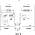
- FIG. 2 is a block diagram illustrating an electronic device 201 including multiple batteries according to an embodiment.
- the electronic device 201 may include a first circuit board 22, a second circuit board 24, a first connector 26, a second connector 28, a first battery 210, a second battery 250, a first sensor 212, a second sensor 252, a first limiter 214, a second limiter 254, a charging/discharging circuit 216, a charging/discharging switch 217, a first system 219, and/or a second system 259.
- the electronic device 201 may be configured to additionally include various components or omit some of the components.
- the electronic device 201 may further include the entirety or some of the electronic device 101 shown in FIG. 1 .
- the electronic device 201 may be applied to a foldable phone (or flip phone) (e.g., the electronic device 700 in FIG. 7 or the electronic device 800 in FIG. 8 ).
- the electronic device 201 when the electronic device 201 is applied to the foldable phone, the electronic device 201 may further include a first housing(eg, the first housing structure 710 in FIG. 7 or the first housing structure 810 in FIG. 8 ) including the first circuit board 22, a second housing (eg, the second housing structure 720 in FIG.
- first housing, the second housing and the hinge structure can be configured such that the first circuit board 22 and the second circuit board 24, which are separated or separated from each other, are electrically connected through the first connector 26 and the second connector 28.
- the electronic device 301 may include a first battery 310, a second battery 350, a first fuel gauge 316, a second fuel gauge 356, a charging circuit 317, a first system 319, and/or a second system 359.
- the electronic device 301 may further include a first circuit board 32, a second circuit board 34, a connector 37, a first sensor 312 and/or a second sensor 352,
- Each of the first battery 310 and the second battery 350 may correspond to a battery housed in the electronic device 301 in an integral form with the electronic device 301 or detachably attached to the electronic device.
- Each of the first battery 310 and the second battery 350 according to an embodiment may be charged according to charging current supply or discharged by providing charged power to the electronic device 301.
- the first battery 310 according to an embodiment may be connected to the first circuit board 32 and the second battery 350 may be connected to the second circuit board 34.
- the second limiter 354 may include a switch and perform switching for connecting or releasing connection between the second battery 350 and the second switch 355. According to the switching operation of the second limiter 354 according to an embodiment, a charging current flow provided from the second battery 350 or provided to the second battery 350 may be blocked or unblocked.
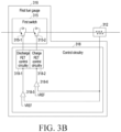
- FIG. 3B is a circuit illustrating a first fuel gauge according to an embodiment.
- the first fuel gauge 316 may include the first switch 315 and control circuitry 318.
- the control circuitry 318 may provide the first interrupt signal corresponding to a first overcurrent to a processor (e.g, processor 320) when the current value of the first battery 310 is a first overcurrent exceeding a designated current value based on the first comparison result and/or the second comparison result.
- the second fuel gauge 356 may include a circuit similar to the first fuel gauge 316 for the second battery 350 and provide the second interrupt signal corresponding to a second overcurrent to a processor (e.g, processor 320) when the current value of the second battery 350 is a second overcurrent exceeding a designated current value based on the first comparison result and/or the second comparison result.
- the electronic device 401 may include a first circuit board 32, a second circuit board 34, a connector 37, a first battery 310, a second battery 350, a first sensor 312, a second sensor 352, a first limiter 314, a first switch 315, a first fuel gauge 316, a second limiter 354, a second switch 355, a second fuel gauge 356, a charging circuit 317, a first system 319, a second system 359, and/or a processor 320.
- the electronic device 401 may further include an additional battery (eg, a third battery), in addition to the first battery 310 and the second battery 350, and a third fuel gauge corresponding to the third battery.
- the number of the plurality of batteries may be two or more, and the number of the plurality of fuel gauges corresponding to the plurality of batteries may be two or more.
- the electronic device 401 may be applied to a foldable phone (or flip phone) (e.g., the electronic device 700 in FIG. 7 or the electronic device 800 in FIG. 8 ).
- the electronic device 401 when the electronic device 401 is applied to the foldable phone (or flip phone), the electronic device 401 may further include a first housing (e.
- the first housing structure 710 in FIG. 7 or the first housing structure 810 in FIG. 8 including the first circuit board 32
- a second housing e. g, the second housing structure 720 in FIG. 7 or the second housing structure 820 in FIG. 8
- a hinge structure eg, the hinge structure 760 in FIG. 7 or the hinge structure 860 in FIG. 8
- the first housing, the second housing and the hinge structure can be configured such that the first circuit board 32 and the second circuit board 34, which are separated or separated from each other, are electrically connected through the connector 37.
- the first circuit board 32, the second circuit board 34, the connector 37, the first battery 310, the second battery 350, the first sensor 312, the second sensor 352, the first limiter 314, the first switch 315, the first fuel gauge 316, the second limiter 354, the second switch 355, the second fuel gauge 356, the charging circuit 317, the first system 319, and the second system 359 may perform substantially the same or similar operations as those described with reference to FIG. 3A and thus an overlapping description will be omitted.
- the processor 320 may identify a discharge state or a charge state of the electronic device 401.
- the processor 320 may control the first fuel gauge 316 to provide the power of the first battery 310 to the at least one first electric component(or the first system 319) and control the second fuel gauge 356 to provide the power of the second battery 350 to the at least one second electrical component(or the second system 359).
- the processor 320 may receive a first interrupt signal corresponding to a first overcurrent related to the first battery 310 from the first fuel gauge 316.
- the processor 320 may receive a second interrupt signal corresponding to a second overcurrent related to the second battery 350 from the second fuel gauge 356.
- the processor 320 may lower clock speed to lower the first overcurrent and/or the second overcurrent.
- the processor 320 may perform a designated control function for reducing a magnitude of a current consumed by the first system 319 and/or the second system 359 to lower the first overcurrent and/or the second overcurrent.
- the designated may include a display brightness control function, a motor control function, and/or a control function for a charging current supplied to an external electronic device (e.g., the OTG device), and may further include other functions to reduce the magnitude of current consumed by the electronic device 401.
- the processor 320 may lower clock speed (or clock frequency) based on the first interrupt signal and/or the second interrupt signal to reduce an amount of a current consumed by the processor 320.
- the processor 320 may lower brightness of a display (e.g., the display 160 in FIG. 1 ) (e.g., LCD) based on the first interrupt signal and/or the second interrupt signal to reduce an amount of a current consumed by the processor 160.
- the processor 320 may lower driving speed of a motor for extending or reducing the display 560 (e.g., a flexible display) of the electronic device 401 based on the first interrupt signal and/or the second interrupt signal to reduce an amount of a current consumed by the motor.
- the processor 320 may lower a magnitude of a charging current supplied to the external electronic device (e.g., the OTG device) connected to the electronic device 401 based on the first interrupt signal and/or the second interrupt signal.
- An electronic device (e.g, the electronic device 101 in FIG. 1 , the electronic device 301 in FIG. 3A , or the electronic device 401 in FIG. 4 ) according to an embodiment may include a first battery (e.g, the first battery 310 in FIG. 3A or FIG. 4 ), a second battery (e.g, the second battery 350 in FIG. 3A or FIG. 4 ), charging circuitry (e.g, the charging circuitry 317 in FIG. 4 ), a processor (e.g, the processor 320 in FIG. 4 ), a first fuel gauge (e.g, the first fuel gauge 316 in FIG.
- a first battery e.g, the first battery 310 in FIG. 3A or FIG. 4
- a second battery e.g, the second battery 350 in FIG. 3A or FIG. 4
- charging circuitry e.g, the charging circuitry 317 in FIG. 4
- a processor e.g, the processor 320 in FIG. 4
- a first fuel gauge e.g, the
- the processor is configured to control the first fuel gauge to provide power of the first battery to a at least one first electric component (e.g, the first system 319 in FIG. 4 ) through the first switch.
- the processor is configured to control the second fuel gauge to provide power of the second battery to at least one second electric component (e.g, the second system 359 in FIG. 4 ) through the second switch.
- the electronic device may further include a first housing (710 in FIG. 7 or 810 in FIG. 8 ) and a second housing (720 in FIG. 7 or 820 in FIG. 7 ).
- the first circuit board is disposed in the first housing
- the second circuit board is disposed in the second housing
- the first circuit board is connected to the second circuit board through a flexible printed circuit board (FPCB).
- the processor is further configured to, based on a discharge state of the electronic device, control the first fuel gauge to provide the power of the first battery to the at least one first electric component and control the second fuel gauge to provide the power of the second battery to the at least one second electrical component.
- the processor is further configured to, based on a charge state of the electronic device, control the charging circuitry to provide input power to the first fuel gauge and the second fuel gauge and control the first fuel gauge to provide the power provided through the charging circuitry to the first battery, and control the second fuel gauge to provide the power provided through the charging circuitry to the second battery.
- the first fuel gauge may transmit a first interrupt signal corresponding to a first overcurrent related to the first battery to the processor, and the second fuel gauge may transmit a second interrupt signal corresponding to a second overcurrent related to the second battery to the processor.
- the processor may be configured to perform a designated function based on the first interrupt signal corresponding to the first overcurrent related to the first battery or the second interrupt signal corresponding to the second overcurrent related to the second battery.
- the first fuel gauge further comprises control circuitry (e.g, the control circuitry 318 in FIG. 3b ).
- the control circuitry is configured to control the first switch based on a comparison between a first voltage of the first battery and a voltage corresponding to a designated discharge allowable current when the first battery is discharged and control the first switch based on a comparison between a second voltage of the first battery and a voltage corresponding to a designated charge allowable current when the first battery is charged.
- the processor may be configured to lower clock speed based on the first interrupt signal corresponding to the first overcurrent related to the first battery or the second interrupt signal corresponding to the second overcurrent related to the second battery.
- the electronic device may further include a display, wherein the processor may be configured to lower brightness of the display based on the first interrupt signal corresponding to the first overcurrent related to the first battery or the second interrupt signal corresponding to the second overcurrent related to the second battery.
- the electronic device may further include a motor, wherein the processor may be configured to lower a speed of the motor based on the first interrupt signal corresponding to the first overcurrent related to the first battery or the second interrupt signal corresponding to the second overcurrent related to the second battery.
- the electronic device may further include interface (e.g., an on the go (OTG) connection part) (e.g., the connecting terminal 178 of the FIG. 1 ), wherein while a charging current is being supplied to an external OTG device connected the electronic device through the OTG connection part, the processor may be configured to lower a magnitude of the charging current supplied to the interface based on the first interrupt signal corresponding to the first overcurrent related to the first battery or the second interrupt signal corresponding to the second overcurrent related to the second battery.
- interface e.g., an on the go (OTG) connection part
- OTG on the go
- the first interrupt signal corresponding to the first overcurrent related to the first battery or the second interrupt signal corresponding to the second overcurrent related to the second battery may correspond to a general purpose input output interrupt request (GPIO IRQ) signal.
- GPIO IRQ general purpose input output interrupt request
- An electronic device (e.g, the electronic device 101 in FIG. 1 , the electronic device 301 in FIG. 3A , or the electronic device 401 in FIG. 4 ) according to an embodiment may include a first circuit board (e.g, the first circuit board 32 in FIG. 3A or FIG. 4 ), a second circuit board (e.g, the second circuit board 34 in FIG. 3A or FIG. 4 ), a connector (e.g, the connector 37 in FIG. 3A or FIG. 4 ) configured to connect the first circuit board and the second circuit board, a first battery (e.g, the first battery 310 in FIG. 3A or FIG. 4 ), a second battery (e.g, the second battery 350 in FIG. 3A or FIG.
- a first circuit board e.g, the first circuit board 32 in FIG. 3A or FIG. 4
- a second circuit board e.g, the second circuit board 34 in FIG. 3A or FIG. 4
- a connector e.g, the connector 37 in FIG. 3A or FIG.
- charging circuitry e.g, the charging circuitry 317 in FIG. 4
- a first fuel gauge e.g, the first fuel gauge 316 in FIG. 4
- a second fuel gauge e.g, the second fuel gauge 356 in FIG. 4
- a second switch e.g, the second switch 355 in FIG. 4
- the first fuel gauge is configured to provide power of the first battery to a at least one first electric component (e.g, the first system 319 in FIG. 4 ) through the first switch and the second fuel gauge is configured to provide power of the second battery to at least one second electric component (e.g, the second system 359 in FIG. 4 ) through the second switch.
- the first battery and the first fuel gauge are disposed on the first circuit board, the second battery and the second fuel gauge are disposed on the second circuit board.
- the first fuel gauge is configured to provide power of the first battery to a at least one first electric component (e.g, the first system 319 in FIG. 4 ) through the first switch and the second fuel gauge is configured to provide power of the second battery to at least one second electric component (e.g, the second system 359 in FIG. 4 ) through the second switch.
- An electronic device (e.g, the electronic device 101 in FIG. 1 , the electronic device 301 in FIG. 3A , or the electronic device 401 in FIG. 4 ) may include a first housing (e.g, the first housing 710 in FIG. 7 ), a second housing (e.g, the second housing 720 in FIG. 7 ) rotatably connected with the first housing, a first circuit board (e.g, the first circuit board 32 in FIG. 3A or FIG. 4 ) disposed in the first housing, a second circuit board (e.g, the second circuit board 34 in FIG. 3A or FIG. 4 ) disposed in the second housing, a connector (e.g, the connector 37 in FIG. 3A or FIG.
- a first battery e.g, the first battery 310 in FIG. 3A or FIG. 4
- a second battery e.g, the second battery 350 in FIG. 3A or FIG. 4
- a first fuel gauge e.g, the first fuel gauge 316 in FIG. 4
- a first switch e.g, the first switch 315 in FIG. 4
- a second fuel gauge e.g, the second fuel gauge 356 in FIG.
- the first fuel gauge is configured to provide power of the first battery to a at least one first electric component (e.g, the first system 319 in FIG. 4 ) through the first switch and the second fuel gauge is configured to provide power of the second battery to at least one second electric component (e.g, the second system 359 in FIG. 4 ) through the second switch.
- a first display e.g, the display 730 in FIG.
- the first display may be a flexible display.
- FIG. 5 is a block diagram illustrating an electronic device according to an embodiment.
- the electronic device 501 may include a first battery 510, a second battery 550, charging circuitry 517, a first sensor 512, a second sensor 552, a first fuel gauge 516, a second fuel gauge 556, a processor (or at least one processor) 520, a memory 530, a display 560, a motor 570, and an interface 580.
- the electronic device 501 may be configured to additionally include various components or omit some of the components.
- the electronic device 501 may further include the entirety or some of the electronic device 101 shown in FIG. 1 .
- the first battery 510, the second battery 550, the charging circuitry 517, the first sensor 512, the second sensor 552, the first fuel gauge 516, and the second fuel gauge 556 in the electronic device 501 may perform the same operations as those of the first battery 310, the second battery 350, the first sensor 312, the second sensor 352, the first fuel gauge 316, and the second fuel gauge 356 described with reference to FIG. 3A , and an overlapping description thereof will be omitted.
- the processor 520 may include a general purpose input output (GPIO) module 522, a control module 524, a driver module 526, and a clock control module 528.
- the GPIO module 522 may receive a first interrupt signal (a GPIO interrupt request (IRQ)) corresponding to a first overcurrent related to the first battery 510 from the first fuel gauge 516.
- the GPIO module 522 may receive a second interrupt signal (a GPIO interrupt request (IRQ)) corresponding to a second overcurrent related to the second battery 520 from the second fuel gauge 556.
- the control module 524 may perform a designated control function for reducing a magnitude of a current consumed by at least one component or module (e.g., the processor 520, the display 560, the motor 570, and/or the interface 580) included in the electronic device 501 to lower the first overcurrent and/or the second overcurrent.
- the driver module 526 may include a motor driver, a display driver, and/or an OTG driver and may perform a driving operation for a designated control function related to the display 560, the motor 570, or the interface 580, based on control of the control module 524.
- the clock control module 528 may lower clock speed (or clock frequency) of the processor 520 less than a designated clock speed based on control of the control module 524.
- the display 560 may lower brightness less than a designated brightness based on performing of a designated control function of the control module 524 (or the driver module 526).
- the interface 580 may include an external device connection part.
- the interface 580 may include OTG connection part for connecting with an external OTG device (not shown).
- the control module 524 (or the driver module 526) may control the charging circuit 517 to lower a magnitude of a charging current supplied to the external OTG device based on performing of a designated function of the processor 520.
- the processor 520 may include multiple processor such as a first processor (e.g, the processor 320) included in the first system 319 as a portion thereof and a second processor (not shown) included in the second system 359 as a portion thereof, and in this case, the first processor may identify the first overcurrent based on the first interrupt signal and by the second processor may identify the second overcurrent based on the second interrupt signal.
- a first processor e.g, the processor 320
- second processor not shown
- the processor 520 may control to lower clock speed of the processor 520 based on the first interrupt signal and/or the second interrupt signal.
- the processor 520 may control to lower brightness of the display 560 based on the first interrupt signal and/or the second interrupt signal.
- the processor 520 according to an embodiment may lower a driving speed of the motor 570 for extending or reducing the display 560 (e.g., a flexible display) based on the first interrupt signal and/or the second interrupt signal.
- the processor 520 may control to lower a magnitude of a charging current supplied to an on the go (OTG) device connected to the electronic device 501 based on the first interrupt signal and/or the second interrupt signal.
- OTG on the go
- FIG. 7 to FIG. 9 are views illustrating a foldable electronic device including a first circuit board, a second circuit board, a first battery, and a second battery according to an embodiment.
- FIG. 7 is a view illustrating a flat state of a foldable electronic device according to an embodiment.
- FIG. 7 illustrates a flat state of the electronic device 700 (e.g., the electronic device 101 in FIG. 1 , the electronic device 301 in FIG. 3A , the electronic device 401 in FIG. 4 , or the electronic device 501 in FIG. 5 ) with reference to a specific folding direction according to an embodiment.
- a first housing structure 710 and a second housing structure 720 may be disposed on opposite sides around folding axis B (e.g., a folding axis in a horizontal direction).
- the first housing structure 710 may additionally include an area in which a camera 714 and various sensors 715 are disposed, but may have a symmetrical shape to the second housing structure in other areas.
- the area in which the camera 714 and the various sensors 715 are disposed may be additionally disposed on at least a partial area of the second housing structure 720 or replaced.
- At least some of the camera 714 and the various sensors 715 may be disposed on at least a partial area of the first housing 710 and the other of the same may be disposed on at least a partial area of the second housing structure 720.
- the first housing structure 710 may include a first surface 711 disposed to face the front surface of the electronic device 700, a second surface 712 facing a direction opposite to the first surface 711, and a first lateral member 713 surrounding at least a portion of a space between the first surface 711 and the second surface 712.
- the second housing structure 720 may include a third surface 721 disposed to face the front surface of the electronic device 700, a fourth surface 722 facing a direction opposite to the third surface 721, and a second lateral member 723 surrounding at least a portion of a space between the third surface 721 and the fourth surface 722.
- the camera module 714 may be exposed to the front surface of the electronic device 700 through an opening formed through one side of the first housing structure 710.
- the sensors 715 may include at least one of a proximity sensor, a light sensor, an iris recognition sensor, an ultrasonic sensor, or an indicator.
- the sensors 715 may be exposed to the front surface of the electronic device 700 through an opening formed through one corner of the first housing structure 710 or may be disposed at a lower end of at least a partial area of the display 730.
- the first housing structure 710 may include a receiver 716 disposed through at least a partial area thereof.
- the electronic device 700 may include an ear jack hole, an external speaker module, a SIM card tray, an interface connector port, or at least one key button disposed through the first housing structure 710 and/or the housing structure 720.
- an angle or a distance between the first housing structure 710 and the second housing structure 720 may vary according to a flat state, a folded state (e.g., a state in FIG. 8 to be described below), or an intermediate state of the electronic device 700.
- a closed state, an open state, and a half-folded state of the electronic device may be determined according to an angle between the first housing structure 710 and the second housing structure 720, and a description thereof will be given below.
- the description of the state may be replaced with a description of a mode.
- the state (e.g., the flat state, the folded state, and the intermediate state) of the electronic device may be determined and depending on the state (e.g., a state of the housings, a state of the hinge, or a curved state of a flexible display) of the electronic device, an operation of display an execution screen of an application may be performed.
- the operation of displaying an execution screen of an application according to a state of the electronic device will be described below.
- the pose of the first housing structure 710 may be detected based on an acceleration sensor of the first motion sensor 740 and the gesture of the first housing structure 710 may be detected based on an angular velocity sensor of the first motion sensor 740.
- the magnetic body 742 may be disposed on at least a portion of the first housing structure 710 adjacent to the hinge structure 760.
- the foldable housing 820 may include a first housing 821 and a second housing 822.
- the first housing 821 may include a first surface 821a and a second surface 821b facing a direction opposite to the first surface 821a
- the second housing 822 may include a third surface 822a and a fifth surface 822b facing a direction opposite to the third surface 822a.
- the foldable housing 820 may additionally or alternatively include a bracket assembly.
- the bracket assembly may include a first bracket assembly 823 disposed on the first housing structure 821 and a second bracket assembly 824 disposed on the second housing structure 822.
- a portion 825 including at least a portion of the bracket assembly, for example, at least a portion of the first bracket assembly 823 and at least a portion of the second bracket assembly 824 may function as a plate for supporting the hinge structure 840.
Landscapes
- Engineering & Computer Science (AREA)
- Power Engineering (AREA)
- Manufacturing & Machinery (AREA)
- Chemical & Material Sciences (AREA)
- Chemical Kinetics & Catalysis (AREA)
- Electrochemistry (AREA)
- General Chemical & Material Sciences (AREA)
- Microelectronics & Electronic Packaging (AREA)
- Charge And Discharge Circuits For Batteries Or The Like (AREA)
Abstract
Description
- The disclosure relates to a method for controlling power based on multiple batteries in an electronic device.
- The use of portable electronic devices such as a smartphone, a tablet PC, a wearable device, and augment glass (AR glass) has been increased and rapid increase in the use of electronic devices may lead to active research on batteries to extend usage time. The electronic devices may be realized to use multiple batteries to receive power.
- An electronic device may include multiple batteries and multiple circuit boards for various functions. According to an embodiment, it is necessary to prevent the electronic device and the batteries from burning out due to flow of an excessive load current while effectively distributing power provided from each of the multiple batteries to electric components or electric elements included in each of the plurality of circuit boards through an optimum power transfer path.
- An electronic device according to an embodiment may include a first battery, a second battery, charging circuitry, a processor, a first fuel gauge connected to the first battery, monitoring usage state information with respect to the first battery, and the charging circuitry and including a first switch for charging or discharging the first battery, and a second fuel gauge connected to the second battery and the charging circuitry, monitoring usage state information with respect to the second battery, and including a second switch for charging or discharging the second battery. In the electronic device according to an embodiment, the processor is configured to control the first fuel gauge to provide power of the first battery to at least one first electrical component through the first switch, and the processor is configured to control the second fuel gauge to provide power of the second battery to at least one second electrical second component through the second switch.
- A method for controlling power based on multiple batteries in an electronic device according to an embodiment may include an operation of receiving a first interrupt signal corresponding to a first overcurrent related to a first battery from a first fuel gauge or a second interrupt signal corresponding to a second overcurrent related to a second battery from a second fuel gauge. The method according to an embodiment may include an operation of identifying the first overcurrent based on the first interrupt signal corresponding to the first overcurrent related to the first battery or identifying the second overcurrent based on the second interrupt signal corresponding to the second overcurrent related to the second battery. The method according to an embodiment may include an operation of performing a designated function based on the identification of the first overcurrent or the second overcurrent.
- A non-transitory recording medium storing instructions according to an embodiment, which, when executed by an electronic device, cause the electronic device to perform at least one operation, wherein the at least one operation may include an operation of receiving a first interrupt signal corresponding to a first overcurrent related to a first battery from a first fuel gauge or a second interrupt signal corresponding to a second overcurrent related to a second battery from a second fuel gauge. The at least one operation according to an embodiment may include an operation of identifying the first overcurrent based on the first interrupt signal corresponding to the first overcurrent related to the first battery or identifying the second overcurrent based on the second interrupt signal corresponding to the second overcurrent related to the second battery. The at least one operation according to an embodiment may include an operation of performing a designated function based on the identification of the first overcurrent or the second overcurrent.
-
-
FIG. 1 is a block diagram illustrating an electronic device in a network environment according to an embodiment. -
FIG. 2 is a block diagram illustrating an electronic device including multiple batteries according to an embodiment. -
FIG. 3A is a block diagram illustrating an electronic device including multiple batteries and multiple fuel gauges according to an embodiment. -
FIG. 3B is a circuit illustrating a first fuel gauge according to an embodiment. -
FIG. 4 is a block diagram illustrating an electronic device including multiple batteries, multiple fuel gauges, and a processor according to an embodiment. -
FIG. 5 is a block diagram illustrating an electronic device according to an embodiment. -
FIG. 6 is a flowchart of a method for controlling power based on multiple batteries in an electronic device according to an embodiment. -
FIG. 7 is a view illustrating a flat state of a foldable electronic device according to an embodiment. -
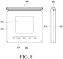
FIG. 8 is a view illustrating a folded state of a foldable electronic device according to an embodiment. -
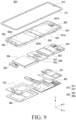
FIG. 9 is an exploded perspective view illustrating a foldable electronic device according to an embodiment. - Terms used in this disclosure are used to describe specified embodiments and may not be intended to limit the scope of another embodiment. The terms of a singular form may include plural forms unless they have a clearly different meaning in the context. All the terms used herein, which include technical or scientific terms, may have the same meaning that is generally understood by a person skilled in the art. It will be further understood that terms, which are defined in a dictionary and commonly used, should also be interpreted as being customary in the relevant related art and not in an idealized or overly formal unless expressly so defined in various embodiments of the disclosure. In some cases, terms, even if defined in the disclosure, may not be interpreted to exclude embodiments of the disclosure.
-
FIG. 1 is a block diagram illustrating anelectronic device 101 in anetwork environment 100 according to an embodiment. Referring toFIG. 1 , theelectronic device 101 in thenetwork environment 100 may communicate with anelectronic device 102 via a first network 198 (e.g., a short-range wireless communication network), or at least one of anelectronic device 104 or aserver 108 via a second network 199 (e.g., a long-range wireless communication network). According to an embodiment, theelectronic device 101 may communicate with theelectronic device 104 via theserver 108. According to an embodiment, theelectronic device 101 may include aprocessor 120,memory 130, aninput module 150, asound output module 155, adisplay module 160, anaudio module 170, asensor module 176, aninterface 177, aconnecting terminal 178, ahaptic module 179, acamera module 180, apower management module 188, abattery 189, acommunication module 190, a subscriber identification module (SIM) 196, or anantenna module 197. In some embodiments, at least one of the components (e.g., the connecting terminal 178) may be omitted from theelectronic device 101, or one or more other components may be added in theelectronic device 101. In some embodiments, some of the components (e.g., thesensor module 176, thecamera module 180, or the antenna module 197) may be implemented as a single component (e.g., the display module 160). - The
processor 120 may execute, for example, software (e.g., a program 140) to control at least one other component (e.g., a hardware or software component) of theelectronic device 101 coupled with theprocessor 120, and may perform various data processing or computation. According to one embodiment, as at least part of the data processing or computation, theprocessor 120 may store a command or data received from another component (e.g., thesensor module 176 or the communication module 190) involatile memory 132, process the command or the data stored in thevolatile memory 132, and store resulting data innon-volatile memory 134. According to an embodiment, theprocessor 120 may include a main processor 121 (e.g., a central processing unit (CPU) or an application processor (AP)), or an auxiliary processor 123 (e.g., a graphics processing unit (GPU), a neural processing unit (NPU), an image signal processor (ISP), a sensor hub processor, or a communication processor (CP)) that is operable independently from, or in conjunction with, themain processor 121. For example, when theelectronic device 101 includes themain processor 121 and the auxiliary processor 123, the auxiliary processor 123 may be adapted to consume less power than themain processor 121, or to be specific to a specified function. The auxiliary processor 123 may be implemented as separate from, or as part of themain processor 121. - The auxiliary processor 123 may control, for example, at least some of functions or states related to at least one component (e.g., the
display module 160, thesensor module 176, or the communication module 190) among the components of theelectronic device 101, instead of themain processor 121 while themain processor 121 is in an inactive (e.g., sleep) state, or together with themain processor 121 while themain processor 121 is in an active (e.g., executing an application) state. According to an embodiment, the auxiliary processor 123 (e.g., an image signal processor or a communication processor) may be implemented as part of another component (e.g., thecamera module 180 or the communication module 190) functionally related to the auxiliary processor 123. According to an embodiment, the auxiliary processor 123 (e.g., the neural processing unit) may include a hardware structure specified for artificial intelligence model processing. An artificial intelligence model may be generated by machine learning. Such learning may be performed, e.g., by theelectronic device 101 where the artificial intelligence model is performed or via a separate server (e.g., the server 108). Learning algorithms may include, but are not limited to, e.g., supervised learning, unsupervised learning, semi-supervised learning, or reinforcement learning. The artificial intelligence model may include a plurality of artificial neural network layers. The artificial neural network may be a deep neural network (DNN), a convolutional neural network (CNN), a recurrent neural network (RNN), a restricted Boltzmann machine (RBM), a deep belief network (DBN), a bidirectional recurrent deep neural network (BRDNN), deep Q-network or a combination of two or more thereof but is not limited thereto. The artificial intelligence model may, additionally or alternatively, include a software structure other than the hardware structure. - The
memory 130 may store various data used by at least one component (e.g., theprocessor 120 or the sensor module 176) of theelectronic device 101. The various data may include, for example, software (e.g., the program 140) and input data or output data for a command related thereto. Thememory 130 may include thevolatile memory 132 or thenon-volatile memory 134. - The
program 140 may be stored in thememory 130 as software, and may include, for example, an operating system (OS) 142,middleware 144, or anapplication 146. - The
input module 150 may receive a command or data to be used by another component (e.g., the processor 120) of theelectronic device 101, from the outside (e.g., a user) of theelectronic device 101. Theinput module 150 may include, for example, a microphone, a mouse, a keyboard, a key (e.g., a button), or a digital pen (e.g., a stylus pen). - The
sound output module 155 may output sound signals to the outside of theelectronic device 101. Thesound output module 155 may include, for example, a speaker or a receiver. The speaker may be used for general purposes, such as playing multimedia or playing record. The receiver may be used for receiving incoming calls. According to an embodiment, the receiver may be implemented as separate from, or as part of the speaker. - The
display module 160 may visually provide information to the outside (e.g., a user) of theelectronic device 101. Thedisplay module 160 may include, for example, a display, a hologram device, or a projector and control circuitry to control a corresponding one of the display, hologram device, and projector. According to an embodiment, thedisplay module 160 may include a touch sensor adapted to detect a touch, or a pressure sensor adapted to measure the intensity of force incurred by the touch. - The
audio module 170 may convert a sound into an electrical signal and vice versa. According to an embodiment, theaudio module 170 may obtain the sound via theinput module 150, or output the sound via thesound output module 155 or an external electronic device (e.g., an electronic device 102 (e.g., a speaker or a headphone)) directly or wirelessly coupled with theelectronic device 101. - The
sensor module 176 may detect an operational state (e.g., power or temperature) of theelectronic device 101 or an environmental state (e.g., a state of a user) external to theelectronic device 101, and then generate an electrical signal or data value corresponding to the detected state. According to an embodiment, thesensor module 176 may include, for example, a gesture sensor, a gyro sensor, an atmospheric pressure sensor, a magnetic sensor, an acceleration sensor, a grip sensor, a proximity sensor, a color sensor, an infrared (IR) sensor, a biometric sensor, a temperature sensor, a humidity sensor, or an illuminance sensor. - The
interface 177 may support one or more specified protocols to be used for theelectronic device 101 to be coupled with the external electronic device (e.g., the electronic device 102) directly or wirelessly. According to an embodiment, theinterface 177 may include, for example, a high definition multimedia interface (HDMI), a universal serial bus (USB) interface, a secure digital (SD) card interface, or an audio interface. - A connecting
terminal 178 may include a connector via which theelectronic device 101 may be physically connected with the external electronic device (e.g., the electronic device 102). According to an embodiment, the connectingterminal 178 may include, for example, an HDMI connector, a USB connector, an SD card connector, or an audio connector (e.g., a headphone connector). - The
haptic module 179 may convert an electrical signal into a mechanical stimulus (e.g., a vibration or a movement) or electrical stimulus which may be recognized by a user via his tactile sensation or kinesthetic sensation. According to an embodiment, thehaptic module 179 may include, for example, a motor, a piezoelectric element, or an electric stimulator. - The
camera module 180 may capture a still image or moving images. According to an embodiment, thecamera module 180 may include one or more lenses, image sensors, image signal processors, or flashes. - The
power management module 188 may manage power supplied to theelectronic device 101. According to one embodiment, thepower management module 188 may be implemented as at least part of, for example, a power management integrated circuit (PMIC). - The
battery 189 may supply power to at least one component of theelectronic device 101. According to an embodiment, thebattery 189 may include, for example, a primary cell which is not rechargeable, a secondary cell which is rechargeable, or a fuel cell. - The
communication module 190 may support establishing a direct (e.g., wired) communication channel or a wireless communication channel between theelectronic device 101 and the external electronic device (e.g., theelectronic device 102, theelectronic device 104, or the server 108) and performing communication via the established communication channel. Thecommunication module 190 may include one or more communication processors that are operable independently from the processor 120 (e.g., the application processor (AP)) and supports a direct (e.g., wired) communication or a wireless communication. According to an embodiment, thecommunication module 190 may include a wireless communication module 192 (e.g., a cellular communication module, a short-range wireless communication module, or a global navigation satellite system (GNSS) communication module) or a wired communication module 194 (e.g., a local area network (LAN) communication module or a power line communication (PLC) module). A corresponding one of these communication modules may communicate with the externalelectronic device 104 via the first network 198 (e.g., a short-range communication network, such as BluetoothTM, wireless-fidelity (Wi-Fi) direct, or infrared data association (IrDA)) or the second network 199 (e.g., a long-range communication network, such as a legacy cellular network, a 5G network, a next-generation communication network, the Internet, or a computer network (e.g., LAN or wide area network (WAN)). These various types of communication modules may be implemented as a single component (e.g., a single chip), or may be implemented as multi components (e.g., multi chips) separate from each other. Thewireless communication module 192 may identify or authenticate theelectronic device 101 in a communication network, such as thefirst network 198 or thesecond network 199, using subscriber information (e.g., international mobile subscriber identity (IMSI)) stored in thesubscriber identification module 196. - The
wireless communication module 192 may support a 5G network, after a 4G network, and next-generation communication technology, e.g., new radio (NR) access technology. The NR access technology may support enhanced mobile broadband (eMBB), massive machine type communications (mMTC), or ultra-reliable and low-latency communications (URLLC). Thewireless communication module 192 may support a high-frequency band (e.g., the mmWave band) to achieve, e.g., a high data transmission rate. Thewireless communication module 192 may support various technologies for securing performance on a high-frequency band, such as, e.g., beamforming, massive multiple-input and multiple-output (massive MIMO), full dimensional MIMO (FD-MIMO), array antenna, analog beam-forming, or large scale antenna. Thewireless communication module 192 may support various requirements specified in theelectronic device 101, an external electronic device (e.g., the electronic device 104), or a network system (e.g., the second network 199). According to an embodiment, thewireless communication module 192 may support a peak data rate (e.g., 20 Gbps or more) for implementing eMBB, loss coverage (e.g., 164 dB or less) for implementing mMTC, or U-plane latency (e.g., 0.5 ms or less for each of downlink (DL) and uplink (UL), or a round trip of 1 ms or less) for implementing URLLC. - The
antenna module 197 may transmit or receive a signal or power to or from the outside (e.g., the external electronic device) of theelectronic device 101. According to an embodiment, theantenna module 197 may include an antenna including a radiating element composed of a conductive material or a conductive pattern formed in or on a substrate (e.g., a printed circuit board (PCB)). According to an embodiment, theantenna module 197 may include a plurality of antennas (e.g., array antennas). In such a case, at least one antenna appropriate for a communication scheme used in the communication network, such as thefirst network 198 or thesecond network 199, may be selected, for example, by thecommunication module 190 from the plurality of antennas. The signal or the power may then be transmitted or received between thecommunication module 190 and the external electronic device via the selected at least one antenna. According to an embodiment, another component (e.g., a radio frequency integrated circuit (RFIC)) other than the radiating element may be additionally formed as part of theantenna module 197. - According to an embodiment, the
antenna module 197 may form a mmWave antenna module. According to an embodiment, the mmWave antenna module may include a printed circuit board, an RFIC disposed on a first surface (e.g., the bottom surface) of the printed circuit board, or adjacent to the first surface and capable of supporting a designated high-frequency band (e.g., the mmWave band), and a plurality of antennas (e.g., array antennas) disposed on a second surface (e.g., the top or a side surface) of the printed circuit board, or adjacent to the second surface and capable of transmitting or receiving signals of the designated high-frequency band. - At least some of the above-described components may be coupled mutually and communicate signals (e.g., commands or data) therebetween via an inter-peripheral communication scheme (e.g., a bus, general purpose input and output (GPIO), serial peripheral interface (SPI), or mobile industry processor interface (MIPI)).
- According to an embodiment, commands or data may be transmitted or received between the
electronic device 101 and the externalelectronic device 104 via theserver 108 coupled with thesecond network 199. Each of the externalelectronic devices electronic device 101. According to an embodiment, all or some of operations to be executed at theelectronic device 101 may be executed at one or more of the externalelectronic devices electronic device 101 should perform a function or a service automatically, or in response to a request from a user or another device, theelectronic device 101, instead of, or in addition to, executing the function or the service, may request the one or more external electronic devices to perform at least part of the function or the service. The one or more external electronic devices receiving the request may perform the at least part of the function or the service requested, or an additional function or an additional service related to the request, and transfer an outcome of the performing to theelectronic device 101. Theelectronic device 101 may provide the outcome, with or without further processing of the outcome, as at least part of a reply to the request. To that end, a cloud computing, distributed computing, mobile edge computing (MEC), or client-server computing technology may be used, for example. Theelectronic device 101 may provide ultra low-latency services using, e.g., distributed computing or mobile edge computing. In another embodiment, the externalelectronic device 104 may include an internet-of-things (IoT) device. Theserver 108 may be an intelligent server using machine learning and/or a neural network. According to an embodiment, the externalelectronic device 104 or theserver 108 may be included in thesecond network 199. Theelectronic device 101 may be applied to intelligent services (e.g., smart home, smart city, smart car, or healthcare) based on 5G communication technology or IoT-related technology. -
FIG. 2 is a block diagram illustrating anelectronic device 201 including multiple batteries according to an embodiment. - Referring to
FIG. 2 , theelectronic device 201 according to an embodiment may include afirst circuit board 22, asecond circuit board 24, afirst connector 26, asecond connector 28, afirst battery 210, asecond battery 250, afirst sensor 212, asecond sensor 252, afirst limiter 214, asecond limiter 254, a charging/dischargingcircuit 216, a charging/dischargingswitch 217, afirst system 219, and/or asecond system 259. - Without limitation thereto, the
electronic device 201 may be configured to additionally include various components or omit some of the components. Theelectronic device 201 according to an embodiment may further include the entirety or some of theelectronic device 101 shown inFIG. 1 . According to an embodiment, theelectronic device 201 may be applied to a foldable phone (or flip phone) (e.g., theelectronic device 700 inFIG. 7 or theelectronic device 800 inFIG. 8 ). According to an embodiment, when theelectronic device 201 is applied to the foldable phone, theelectronic device 201 may further include a first housing(eg, thefirst housing structure 710 inFIG. 7 or thefirst housing structure 810 inFIG. 8 ) including thefirst circuit board 22, a second housing (eg, thesecond housing structure 720 inFIG. 7 or thesecond housing structure 820 inFIG. 8 ) including asecond circuit board 24, a hinge structure (eg, thehinge structure 760 inFIG. 7 or thehinge structure 860 inFIG. 8 ) connected between the first housing and the second housing. According to one embodiment, the first housing, the second housing and the hinge structure can be configured such that thefirst circuit board 22 and thesecond circuit board 24, which are separated or separated from each other, are electrically connected through thefirst connector 26 and thesecond connector 28. - The
first circuit board 22 and thesecond circuit board 24 according to an embodiment may include a printed circuit board (PCB) or a flexible printed circuit board (FPCB) and may include (or provided with) electric components (or modules)(or electric elements) (e.g., thefirst system 219 and the second system 259) required for an operation of theelectronic device 201. For example, thefirst circuit board 22 may include the first system 219 (e.g., at least one first electric component (or at least one first electric element) required for an operation of the electronic device 201) and thesecond circuit board 24 may include the second system 259 (e.g., at least one second electric component (or at least one second electric element) required for an operation of the electronic device 201). - The
first connector 26 and thesecond connector 28 according to an embodiment may correspond to connection parts for connecting a wire (or an electrical path) between thefirst circuit board 22 and thesecond circuit board 24. Thefirst connector 26 may be a connection part for connecting a first wire related to charging/discharging of thefirst battery 210 and thesecond battery 250. Thesecond connector 28 may be a connection part for connecting a second wire related to power supplying to thesecond system 259. - Each of the
first battery 210 and thesecond battery 250 according to an embodiment may correspond to a battery housed in theelectronic device 201 in an integral form with theelectronic device 201 or detachably attached to the electronic device. Each of thefirst battery 210 and thesecond battery 250 according to an embodiment may be charged according to charging current supply or discharged by providing charged power to theelectronic device 201. Thefirst battery 210 according to an embodiment may be connected to thefirst circuit board 22 and thesecond battery 250 may be connected to thesecond circuit board 24. - Each of the
first battery 210 and thesecond battery 250 according to an embodiment may supply power to a main body (or thefirst system 219 and/or thesecond system 259 included in the electronic device 201) of theelectronic device 201 or may be charged by using power provided from an external power source through the charging/dischargingcircuit 216. Charge capacities of thefirst battery 210 and thesecond battery 250 according to an embodiment may be identical to or different from each other. For example, a charge capacity of the first battery 210 (e.g., a main battery) may be larger than that of the second battery 250 (e.g., a sub-battery). - The first sensor 212 (e.g., a first current sensor) and the second sensor 252 (e.g., a second current sensor) according to an embodiment may be configured to measure currents (and/or voltages) with respect to the
first battery 210 and thesecond battery 250, respectively. According to an embodiment theelectronic device 201 may further include an additional sensor for measuring a temperature of each of thefirst battery 210 and thesecond battery 250 in addition to thefirst sensor 212 and thesecond sensor 252. Thefirst sensor 212 and thesecond sensor 252 according to an embodiment may measure a current, a voltage, and a temperature of each of thefirst battery 210 and thesecond battery 250 in real time or periodically or repetitively or based on occurrence of an event, a measurement period with respect to one of the current, the voltage, and the temperature may be the same as or different from that of the others. - The
first limiter 214 according to an embodiment may include a switch and perform switching for connecting or releasing connection between thefirst battery 210 and the charging/dischargingcircuit 216 between thefirst battery 210 and the charging/dischargingcircuit 216. According to the switching operation of thefirst limiter 214 according to an embodiment, a charging current flow provided from thefirst battery 210 or provided to thefirst battery 210 may be blocked or unblocked. For example, thefirst limiter 214 may include a switch for performing a turn on or turn off operation. - The
second limiter 254 according to an embodiment may perform switching for connecting or releasing connection between thesecond battery 250 and the charging/dischargingcircuit 216 between thesecond battery 250 and the charging/dischargingcircuit 216. According to the switching operation of thesecond limiter 254, a charging current flow provided from thesecond battery 250 or provided to thesecond battery 250 may be blocked or unblocked. For example, thesecond limiter 254 may include a switch for performing a turn on or turn off operation. - The charging/discharging circuit 216 (e.g., a charging IC) according to an embodiment may include a charging/discharging switch (or switches) 217 for performing a charging operation or a discharging operation with respect to the
first battery 210 and/or thesecond battery 250. The charging/dischargingcircuit 216 may be configured to selectively execute a charging operation and a discharging operation with respect to thefirst battery 210 and/or thesecond battery 250. The charging/dischargingcircuit 216 may convert power supplied from an external power supply device (or an external power source) through an interface (not shown) (e.g., a wired charging interface and/or a wireless charging interface) to a voltage (and/or a current) corresponding to thefirst battery 210 and/or thesecond battery 250 to be supplied to thefirst battery 210 and/or thesecond battery 250. The charging/dischargingcircuit 216 may supply power supplied from thefirst battery 210 or thesecond battery 250 through the charging/dischargingswitch 217 to a main body of theelectronic device 201, for example, each component (e.g., thefirst system 219 and/or the second system 259) or supply power supplied from thefirst battery 210 to thesecond battery 250. According to an embodiment, the charging/dischargingswitch 217 may perform a switching operation for allowing that the charging/dischargingcircuit 216 supply power to thefirst battery 210 and/or thesecond battery 250 or adjusts power or a current supplied from thefirst battery 210 and/or thesecond battery 250 based on a control signal output from a processor (e.g., theprocessor 120 inFIG. 1 ). - The charging/discharging
circuit 216 according to an embodiment may control, based on a comparison result between a charge capacity of thesecond battery 250 and a designated threshold charge capacity range, turning on or turning off of thefirst limiter 214 for performing switching between thefirst battery 210 and the charging/dischargingcircuit 216 and asecond limiter 254 for performing switching between thesecond battery 250 and the charging/dischargingcircuit 216. According to an embodiment, the turning on or turning off of thefirst limiter 214 and thesecond limiter 254 may be controlled by a processor (e.g., theprocessor 120 inFIG. 1 ). - In the
electronic device 201 shown inFIG. 2 according to an embodiment, the charging/dischargingcircuit 216 may distinguish a overcurrent based on a current (an integrated current by thefirst battery 210 and the second battery 250) transferred through the charging/dischargingswitch 217 and transfer overcurrent occurrence to the processor (e.g., 120) so as to perform an operation for lowering an overcurrent according to a control signal from the processor. An overcurrent may cause a misoperation of theelectronic device 201 or damage to the battery and thus in case that an overcurrent occurs in theelectronic device 201, protection circuit modulation (PCM) blocking or a sudden momentary power loss (SMPL) reset may occur in theelectronic device 201. In case that the protection circuit modulation (PCM) blocking or the sudden momentary power loss (SMPL) reset occurs, theelectronic device 201 may be powered off and thus a control operation of lowering an overcurrent may be important. - For example, A longer a distance between the first battery 210 (and/or the second battery 250) and at least one electric component (or at least one electric element)(e.g, the
first system 219 or the second system 259) to receive a current from the first battery 210(and/or the second battery 250), a length of a power transfer path (e.g., a power line) may increase. According to an embodiment, as the length of the power transfer path increases, an internal resistance of the power transmission path may increase to cause an overcurrent, and the overcurrent may cause the PCM blocking or the SMPL reset in theelectronic device 201. - For example, in
FIG. 2 , a power transfer path (①) through thesecond limiter 254, thefirst connector 26, charging/dischargingcircuit 216, and thesecond connector 28 may be formed to cause a current to be transferred from thesecond battery 250 to thesecond system 259 and in case that a distance of the power transfer path ((I)) may be reduced, overcurrent occurrence may be reduced and effective power transfer may be possible. -
FIG. 3A is a block diagram illustrating an electronic device including multiple batteries and multiple fuel gauges according to an embodiment. - Referring to
FIG. 3A , the electronic device 301 (e.g., theelectronic device 101 inFIG. 1 ) according to an embodiment may include afirst battery 310, asecond battery 350, afirst fuel gauge 316, asecond fuel gauge 356, a chargingcircuit 317, afirst system 319, and/or asecond system 359. According to an embodiment, theelectronic device 301 may further include afirst circuit board 32, asecond circuit board 34, aconnector 37, afirst sensor 312 and/or asecond sensor 352, - Without limitation thereto, the
electronic device 301 according to an embodiment may be configured to additionally include various components or omit some of the components. Theelectronic device 301 according to an embodiment may further include the entirety or some of theelectronic device 101 shown inFIG. 1 . According to an embodiment, theelectronic device 301 may be applied to a foldable phone (or flip phone) (e.g., theelectronic device 700 inFIG. 7 or theelectronic device 800 inFIG. 8 ). According to an embodiment, when theelectronic device 301 is applied to the foldable phone(or flip phone), theelectronic device 301 may further include a first housing (e. g, thefirst housing structure 710 inFIG. 7 or thefirst housing structure 810 inFIG. 8 ) including thefirst circuit board 32, a second housing (e. g, thesecond housing structure 720 inFIG. 7 or thesecond housing structure 820 inFIG. 8 ) including asecond circuit board 34, and a hinge structure (e. g, thehinge structure 760 inFIG. 7 or thehinge structure 860 inFIG. 8 ) connected between the first housing and the second housing. According to one embodiment, the first housing, the second housing and the hinge structure can be configured such that thefirst circuit board 32 and thesecond circuit board 34, which are separated or separated from each other, are electrically connected through theconnector 37. - The
first circuit board 32 and thesecond circuit board 34 according to an embodiment may include a printed circuit board (PCB) or a flexible printed circuit board (FPCB) and may include (or provided with) electrical components (or electrical modules, or electrical elements) (e.g., thefirst system 319 and the second system 359) required for an operation of theelectronic device 301. For example, thefirst circuit board 32 may include the first system 319 (e.g., some of electrical components (or electrical modules or electrical elements) required for an operation of the electronic device 301) and thesecond circuit board 34 may include the second system 359 (e.g., some of other electrical components (or electrical modules or electrical elements) required for an operation of the electronic device 301). According to an embodiment, thefirst system 319 includes at least one first electrical element or at least one first electrical component. According to an embodiment, thesecond system 359 includes at least one second electrical element or at least one second electrical component. For example, thefirst system 319 includes at least part of electrical elements or electrical components included in theelectronic device 101 of theFIG. 1 , and thesecond system 359 includes at least another part of the electrical elements or the electrical components included in theelectronic device 101 of theFIG. 1 . Theconnector 37 according to an embodiment may correspond to a connection part for connecting a wire (or an electrical path) related to power transfer between thefirst circuit board 32 and thesecond circuit board 34. - Each of the
first battery 310 and thesecond battery 350 according to an embodiment may correspond to a battery housed in theelectronic device 301 in an integral form with theelectronic device 301 or detachably attached to the electronic device. Each of thefirst battery 310 and thesecond battery 350 according to an embodiment may be charged according to charging current supply or discharged by providing charged power to theelectronic device 301. Thefirst battery 310 according to an embodiment may be connected to thefirst circuit board 32 and thesecond battery 350 may be connected to thesecond circuit board 34. - Each of the
first battery 310 and thesecond battery 350 according to an embodiment may supply power to a main body (or thefirst system 319 and/or thesecond system 359 included in the electronic device 301) of theelectronic device 301 or may be charged by using power provided from an external power source through the chargingcircuit 317. Charge capacities of thefirst battery 310 and thesecond battery 350 according to an embodiment may be identical to or different from each other. For example, a charge capacity of the first battery 310 (e.g., a main battery) may be larger than that of the second battery 350 (e.g., a sub-battery). - The first sensor 312 (e.g., a first current sensor) and the second sensor 352 (e.g., a first current sensor) according to an embodiment may be configured to measure currents (and/or voltages) with respect to the
first battery 310 and thesecond battery 350, respectively. According to an embodiment theelectronic device 301 may further include an additional sensor for measuring a temperature of each of thefirst battery 310 and thesecond battery 350 in addition to thefirst sensor 312 and thesecond sensor 352. Thefirst sensor 312 and thesecond sensor 352 according to an embodiment may measure a current (or a voltage or a temperature) of each of thefirst battery 310 and thesecond battery 350 in real time or periodically or repetitively or based on occurrence of an event, a measurement period with respect to one of the current, the voltage, and the temperature may be the same as or different from that of the others. - The first fuel gauge (or a first power gauge) 316 according to an embodiment may measure or monitor usage state information (e.g., a capacity, charging/discharging numbers, a voltage, or a temperature of the first battery 310) with respect to the
first battery 310. Thefirst fuel gauge 316 according to an embodiment may also be referred to as a first circuit. The first circuit may be a circuit capable of measuring state information of thefirst battery 310 and performing switching for charging or discharging thefirst battery 310. - The
first fuel gauge 316 according to an embodiment may include thefirst limiter 314 and thefirst switch 315 and control thefirst limiter 314 and thefirst switch 315. According to an embodiment, thefirst switch 315 may be realized to perform functions of each of thefirst limiter 314 and thefirst switch 315 together and thefirst fuel gauge 316 may control thefirst switch 315. According to an embodiment, thefirst fuel gauge 316 may control that the first electrical power of thefirst battery 310 is provided to the first system 319 (or the first path or the first electrical wire corresponding to the first system 319) through thefirst switch 315. - The
first limiter 314 according to an embodiment may include a switch and perform switching for connecting or releasing connection between thefirst battery 310 and thefirst circuit 315. According to the switching operation of thefirst limiter 314 according to an embodiment, a charging current flow provided from thefirst battery 310 or provided to thefirst battery 310 may be blocked or unblocked. - The
first switch 315 according to an embodiment may supply power supplied from thefirst battery 310 to a main body of theelectronic device 301, for example, each component (e.g., thefirst system 319 and/or the second system 359) or supply power supplied from thefirst battery 310 to thesecond battery 350. According to an embodiment, thefirst switch 315 may perform a switching for being supplied power to thefirst battery 310 or being adjusted power or a current supplied from thefirst battery 310 based on a control signal output from the first fuel gauge 316 (or a processor (e.g., theprocessor 120 inFIG. 1 )). - The second fuel gauge (or a second power gauge) 356 according to an embodiment may measure or monitor usage state information (e.g., a capacity, charging/discharging numbers, a voltage, or a temperature of the second battery 350) with respect to the
second battery 350. Thesecond fuel gauge 356 according to an embodiment may also be referred to as a second circuit. The second circuit may be a circuit capable of measuring state information of thesecond battery 350 and performing switching for charging or discharging thesecond battery 350. - The
second fuel gauge 356 according to an embodiment may include thesecond limiter 354 and thesecond switch 355 and control thesecond limiter 354 and thesecond switch 355. According to an embodiment, thesecond fuel gauge 356 may control that the second electrical power of thesecond battery 350 is provided to the second system 359 (or the second path or the second electrical wire corresponding to the second system 359) through thesecond switch 355. - According to an embodiment, the
second switch 355 may be realized to perform functions of each of thesecond limiter 354 and thesecond switch 355 together and thesecond fuel gauge 356 may control thesecond switch 355. - The
second limiter 354 according to an embodiment may include a switch and perform switching for connecting or releasing connection between thesecond battery 350 and thesecond switch 355. According to the switching operation of thesecond limiter 354 according to an embodiment, a charging current flow provided from thesecond battery 350 or provided to thesecond battery 350 may be blocked or unblocked. - The
second switch 355 according to an embodiment may supply power supplied from thesecond battery 350 to a main body of theelectronic device 301, for example, each component (e.g., thefirst system 319 and/or thesecond system 359 supply power supplied from thefirst battery 310 to thesecond battery 350. According to an embodiment, thesecond switch 355 may perform a switching operation of supplying power to thesecond battery 350 according to a control signal output from the second fuel gauge 356 (or a processor (e.g., theprocessor 120 inFIG. 1 )) or allowing power or a current supplied from thesecond battery 350 to be adjustable. - The charging circuit 317 (e.g., a charging IC) according to an embodiment may perform a charging operation with respect to the
first battery 310 and/or thesecond battery 350. The chargingcircuit 317 may convert power supplied from an external power supply device (or an external power source) through an interface (e.g., theinterface 177 inFIG. 1 ) (e.g., a wired charging interface and/or a wireless charging interface) to a voltage (and/or a current) corresponding to thefirst battery 310 and/or thesecond battery 350 to be supplied to thefirst battery 310 and/or thesecond battery 350. - In the
electronic device 301 inFIG. 3A according to an embodiment, thefirst fuel gauge 316 may distinguish a first overcurrent related to thefirst battery 310 based on a current of thefirst battery 310 transferred through thefirst switch 315 and thesecond fuel gauge 356 may distinguish a second overcurrent related to thesecond battery 350 based on a current of thesecond battery 350 transferred through thesecond switch 355. Thefirst fuel gauge 316 may transfer a first interrupt signal corresponding to the first overcurrent to a processor (e.g., theprocessor 120 inFIG. 1 ) and thesecond fuel gauge 356 may transfer a second interrupt signal corresponding to the second overcurrent to a processor (e.g., 120). The processor may perform a control operation for lowering the first overcurrent and/or the second overcurrent depending on the first interrupt signal and/or the second interrupt signal. - In
FIG. 3A according to an embodiment, in case that a current is transferred from thesecond battery 350 to thesecond system 359, a power transfer path ((2)) may be formed through thesecond limiter 354 and thesecond switch 355 excluding theconnector 37 and as a length of the power transfer path ((2)) is reduced compared to that(CD) ofFIG. 2 , the possibility of overcurrent occurrence may also be reduced. -
FIG. 3B is a circuit illustrating a first fuel gauge according to an embodiment. - Referring to
FIG. 3B , thefirst fuel gauge 316 according to an embodiment may include thefirst switch 315 andcontrol circuitry 318. - According to an embodiment, the
control circuitry 318 may control thefirst switch 315. - According to an embodiment, the
first switch 315 may include a discharging FET (or a first FET) 315-1 and a charging FET(or a second FET) 315-2. The discharging FET 315-1 according to an embodiment may perform switching such that current flows through a discharge path for thefirst battery 310. The charging FET 315-2 according to an embodiment may perform switching such that current flows through a charge path for thefirst battery 310. - According to an embodiment, the
control circuitry 318 may include discharging FET control circuitry (or first FET control circuitry) 318-1, charging FET control circuitry (or second FET control circuitry) 318-2, a first comparator 318-5, and a second comparator 318-6. The first comparator 318-5 according to an embodiment may compare a first voltage sensed by the first sensor 312(e.g, a voltage sensor) based on current provided to thefirst switch 315 from thefirst battery 310 with a voltage corresponding to a designated allowable discharge current and output a first comparison result. The second comparator 318-6 according to an embodiment may compare a second voltage sensed by the first sensor 312(e.g, a voltage sensor) based on current provided to thefirst battery 310 from thefirst switch 315 with a voltage corresponding to a designated allowable charge current and output a second comparison result. The discharging FET control circuitry 318-1 according to an embodiment may control an operation of thefirst swith 315 based on the first comparison result. The charging FET control circuitry 318-2 according to an embodiment may control an operation of thefirst swith 315 based on the second comparison result. Thecontrol circuitry 318 according to an embodiment may provide the first interrupt signal corresponding to a first overcurrent to a processor (e.g, processor 320) when the current value of thefirst battery 310 is a first overcurrent exceeding a designated current value based on the first comparison result and/or the second comparison result. Thesecond fuel gauge 356 according to an embodiment may include a circuit similar to thefirst fuel gauge 316 for thesecond battery 350 and provide the second interrupt signal corresponding to a second overcurrent to a processor (e.g, processor 320) when the current value of thesecond battery 350 is a second overcurrent exceeding a designated current value based on the first comparison result and/or the second comparison result. -
FIG. 4 is a block diagram illustrating an electronic device including multiple batteries, multiple fuel gauges, and a processor according to an embodiment. - Referring to
FIG. 4 , the electronic device 401 (e.g., theelectronic device 101 inFIG. 1 ) according to an embodiment may include afirst circuit board 32, asecond circuit board 34, aconnector 37, afirst battery 310, asecond battery 350, afirst sensor 312, asecond sensor 352, afirst limiter 314, afirst switch 315, afirst fuel gauge 316, asecond limiter 354, asecond switch 355, asecond fuel gauge 356, a chargingcircuit 317, afirst system 319, asecond system 359, and/or aprocessor 320. - Without limitation thereto, the
electronic device 401 may be configured to additionally include various components or omit some of the components. Theelectronic device 401 according to an embodiment may further include the entirety or some of theelectronic device 101 shown inFIG. 1 . - According to an embodiment, the
electronic device 401 may further include an additional battery (eg, a third battery), in addition to thefirst battery 310 and thesecond battery 350, and a third fuel gauge corresponding to the third battery. According to an embodiment, The number of the plurality of batteries may be two or more, and the number of the plurality of fuel gauges corresponding to the plurality of batteries may be two or more. According to an embodiment, theelectronic device 401 may be applied to a foldable phone (or flip phone) (e.g., theelectronic device 700 inFIG. 7 or theelectronic device 800 inFIG. 8 ). According to an embodiment, when theelectronic device 401 is applied to the foldable phone (or flip phone), theelectronic device 401 may further include a first housing (e. g, thefirst housing structure 710 inFIG. 7 or thefirst housing structure 810 inFIG. 8 ) including thefirst circuit board 32, a second housing (e. g, thesecond housing structure 720 inFIG. 7 or thesecond housing structure 820 inFIG. 8 ) including asecond circuit board 34, and a hinge structure (eg, thehinge structure 760 inFIG. 7 or thehinge structure 860 inFIG. 8 ) connected between the first housing and the second housing. According to one embodiment, the first housing, the second housing and the hinge structure can be configured such that thefirst circuit board 32 and thesecond circuit board 34, which are separated or separated from each other, are electrically connected through theconnector 37. - In the
electronic device 401 according to an embodiment, thefirst circuit board 32, thesecond circuit board 34, theconnector 37, thefirst battery 310, thesecond battery 350, thefirst sensor 312, thesecond sensor 352, thefirst limiter 314, thefirst switch 315, thefirst fuel gauge 316, thesecond limiter 354, thesecond switch 355, thesecond fuel gauge 356, the chargingcircuit 317, thefirst system 319, and thesecond system 359 may perform substantially the same or similar operations as those described with reference toFIG. 3A and thus an overlapping description will be omitted. - The
processor 320 according to an embodiment may be included in thefirst circuit board 32 and may be included as a portion of thefirst system 319 or separately. Theprocessor 320 according to an embodiment may be referred to as at least one processor. Theelectronic device 401 according to an embodiment may include multiple processors (e.g., a first processor and a second processor), the first processor (e.g., the processor 320) may be included in thefirst circuit board 32 as a portion of thefirst system 319 or separately, and the second processor (not shown) may be included in thesecond circuit board 34 as a portion of thesecond system 359 or separately. - The processor 320 (e.g., the
processor 120 inFIG. 1 ) according to an embodiment may control overall operations of theelectronic device 401 and may control an operation related to charging/discharging of thefirst battery 310 and thesecond battery 350. - The
processor 320 according to an embodiment may identify a discharge state or a charge state of theelectronic device 401. Theprocessor 320 according to an embodiment, based on the discharge state of theelectronic device 401, may control thefirst fuel gauge 316 to provide the power of thefirst battery 310 to the at least one first electric component(or the first system 319) and control thesecond fuel gauge 356 to provide the power of thesecond battery 350 to the at least one second electrical component(or the second system 359). Theprocessor 320 according to an embodiment, based on the charge state of theelectronic device 401, control the chargingcircuitry 317 to provide input power to thefirst fuel gauge 316 and thesecond fuel gauge 356 and control thefirst fuel gauge 316 to provide the power provided through the chargingcircuitry 317 to thefirst battery 310, and control thesecond fuel gauge 356 to provide the power provided through the chargingcircuitry 317 to thesecond battery 350. - The
processor 320 according to an embodiment may receive a first interrupt signal corresponding to a first overcurrent related to thefirst battery 310 from thefirst fuel gauge 316. Theprocessor 320 according to an embodiment may receive a second interrupt signal corresponding to a second overcurrent related to thesecond battery 350 from thesecond fuel gauge 356. - Based on receiving the first interrupt signal and/or the second interrupt signal, the
processor 320 according to an embodiment may lower clock speed to lower the first overcurrent and/or the second overcurrent. In case of receiving the first interrupt signal and/or the second interrupt signal, theprocessor 320 according to an embodiment may perform a designated control function for reducing a magnitude of a current consumed by thefirst system 319 and/or thesecond system 359 to lower the first overcurrent and/or the second overcurrent. For example, the designated may include a display brightness control function, a motor control function, and/or a control function for a charging current supplied to an external electronic device (e.g., the OTG device), and may further include other functions to reduce the magnitude of current consumed by theelectronic device 401. - The
processor 320 according to an embodiment may lower clock speed (or clock frequency) based on the first interrupt signal and/or the second interrupt signal to reduce an amount of a current consumed by theprocessor 320. Theprocessor 320 according to an embodiment may lower brightness of a display (e.g., thedisplay 160 inFIG. 1 ) (e.g., LCD) based on the first interrupt signal and/or the second interrupt signal to reduce an amount of a current consumed by theprocessor 160. Theprocessor 320 according to an embodiment may lower driving speed of a motor for extending or reducing the display 560 (e.g., a flexible display) of theelectronic device 401 based on the first interrupt signal and/or the second interrupt signal to reduce an amount of a current consumed by the motor. Theprocessor 320 according to an embodiment may lower a magnitude of a charging current supplied to the external electronic device (e.g., the OTG device) connected to theelectronic device 401 based on the first interrupt signal and/or the second interrupt signal. - An electronic device (e.g, the
electronic device 101 inFIG. 1 , theelectronic device 301 inFIG. 3A , or theelectronic device 401 inFIG. 4 ) according to an embodiment may include a first battery (e.g, thefirst battery 310 inFIG. 3A orFIG. 4 ), a second battery (e.g, thesecond battery 350 inFIG. 3A orFIG. 4 ), charging circuitry (e.g, the chargingcircuitry 317 inFIG. 4 ), a processor (e.g, theprocessor 320 inFIG. 4 ), a first fuel gauge (e.g, thefirst fuel gauge 316 inFIG. 4 ) connected to the first battery and the charging circuitry, monitoring usage state information with respect to the first battery, and including a first switch (e.g, thefirst switch 315 inFIG. 4 ) for charging or discharging the first battery, and a second fuel gauge (e.g, thesecond fuel gauge 356 inFIG. 4 ) connected to the second battery and the charging circuitry, monitoring usage state information with respect to the second battery, and including a second switch (e.g, thesecond switch 355 inFIG. 4 ) for charging or discharging the second battery. In the electronic device according to an embodiment, the processor is configured to control the first fuel gauge to provide power of the first battery to a at least one first electric component (e.g, thefirst system 319 inFIG. 4 ) through the first switch. In the electronic device according to an embodiment, the processor is configured to control the second fuel gauge to provide power of the second battery to at least one second electric component (e.g, thesecond system 359 inFIG. 4 ) through the second switch. - The electronic device according to an embodiment may further include a first circuit board (e.g, the
first circuit board 32 inFIG. 3A orFIG. 4 ), a second circuit board (e.g, thesecond circuit board 34 inFIG. 3A orFIG. 4 ), and a connector (e.g, theconnector part 37 inFIG. 3A orFIG. 4 ) for connecting the first circuit board and the second circuit board. In the electronic device according to an embodiment, the charging circuitry, the first battery and the first fuel gauge may be disposed on the first circuit board and the second battery and the second fuel gauge may be disposed on the second circuit board. - The electronic device according to an embodiment may further include a first housing (710 in
FIG. 7 or 810 inFIG. 8 ) and a second housing (720 inFIG. 7 or 820 inFIG. 7 ). In the electronic device according to an embodiment, the first circuit board is disposed in the first housing, the second circuit board is disposed in the second housing, and the first circuit board is connected to the second circuit board through a flexible printed circuit board (FPCB). In the electronic device according to an embodiment, the processor is further configured to, based on a discharge state of the electronic device, control the first fuel gauge to provide the power of the first battery to the at least one first electric component and control the second fuel gauge to provide the power of the second battery to the at least one second electrical component. In the electronic device according to an embodiment, the processor is further configured to, based on a charge state of the electronic device, control the charging circuitry to provide input power to the first fuel gauge and the second fuel gauge and control the first fuel gauge to provide the power provided through the charging circuitry to the first battery, and control the second fuel gauge to provide the power provided through the charging circuitry to the second battery. - The electronic device according to an embodiment, wherein the first fuel gauge may transmit a first interrupt signal corresponding to a first overcurrent related to the first battery to the processor, and the second fuel gauge may transmit a second interrupt signal corresponding to a second overcurrent related to the second battery to the processor.
- The processor according to an embodiment may be configured to perform a designated function based on the first interrupt signal corresponding to the first overcurrent related to the first battery or the second interrupt signal corresponding to the second overcurrent related to the second battery.
- The first fuel gauge according to an embodiment further comprises control circuitry (e.g, the
control circuitry 318 inFIG. 3b ). The control circuitry according to an embodiment is configured to control the first switch based on a comparison between a first voltage of the first battery and a voltage corresponding to a designated discharge allowable current when the first battery is discharged and control the first switch based on a comparison between a second voltage of the first battery and a voltage corresponding to a designated charge allowable current when the first battery is charged. - The processor according to an embodiment may be configured to lower clock speed based on the first interrupt signal corresponding to the first overcurrent related to the first battery or the second interrupt signal corresponding to the second overcurrent related to the second battery.
- The electronic device according to an embodiment may further include a display, wherein the processor may be configured to lower brightness of the display based on the first interrupt signal corresponding to the first overcurrent related to the first battery or the second interrupt signal corresponding to the second overcurrent related to the second battery.
- The electronic device according to an embodiment may further include a motor, wherein the processor may be configured to lower a speed of the motor based on the first interrupt signal corresponding to the first overcurrent related to the first battery or the second interrupt signal corresponding to the second overcurrent related to the second battery.
- The electronic device according to an embodiment may further include interface (e.g., an on the go (OTG) connection part) (e.g., the connecting
terminal 178 of theFIG. 1 ), wherein while a charging current is being supplied to an external OTG device connected the electronic device through the OTG connection part, the processor may be configured to lower a magnitude of the charging current supplied to the interface based on the first interrupt signal corresponding to the first overcurrent related to the first battery or the second interrupt signal corresponding to the second overcurrent related to the second battery. - According to an embodiment, the first interrupt signal corresponding to the first overcurrent related to the first battery or the second interrupt signal corresponding to the second overcurrent related to the second battery may correspond to a general purpose input output interrupt request (GPIO IRQ) signal.
- An electronic device (e.g, the
electronic device 101 inFIG. 1 , theelectronic device 301 inFIG. 3A , or theelectronic device 401 inFIG. 4 ) according to an embodiment may include a first circuit board (e.g, thefirst circuit board 32 inFIG. 3A orFIG. 4 ), a second circuit board (e.g, thesecond circuit board 34 inFIG. 3A orFIG. 4 ), a connector (e.g, theconnector 37 inFIG. 3A orFIG. 4 ) configured to connect the first circuit board and the second circuit board, a first battery (e.g, thefirst battery 310 inFIG. 3A orFIG. 4 ), a second battery (e.g, thesecond battery 350 inFIG. 3A orFIG. 4 ), charging circuitry (e.g, the chargingcircuitry 317 inFIG. 4 ), a first fuel gauge (e.g, thefirst fuel gauge 316 inFIG. 4 ) connected to the first battery and the charging circuitry and including a first switch (e.g, thefirst switch 315 inFIG. 4 ) for charging or discharging the first battery, and a second fuel gauge (e.g, thesecond fuel gauge 356 inFIG. 4 ) connected to the second battery and the charging circuitry and including a second switch (e.g, thesecond switch 355 inFIG. 4 ) for charging or discharging the second battery. In the electronic device according to an embodiment, the first fuel gauge is configured to provide power of the first battery to a at least one first electric component (e.g, thefirst system 319 inFIG. 4 ) through the first switch and the second fuel gauge is configured to provide power of the second battery to at least one second electric component (e.g, thesecond system 359 inFIG. 4 ) through the second switch. In the electronic device according to an embodiment, the first battery and the first fuel gauge are disposed on the first circuit board, the second battery and the second fuel gauge are disposed on the second circuit board. In the electronic device according to an embodiment, the first fuel gauge is configured to provide power of the first battery to a at least one first electric component (e.g, thefirst system 319 inFIG. 4 ) through the first switch and the second fuel gauge is configured to provide power of the second battery to at least one second electric component (e.g, thesecond system 359 inFIG. 4 ) through the second switch. - An electronic device (e.g, the
electronic device 101 inFIG. 1 , theelectronic device 301 inFIG. 3A , or theelectronic device 401 inFIG. 4 ) according to an embodiment may include a first housing (e.g, thefirst housing 710 inFIG. 7 ), a second housing (e.g, thesecond housing 720 inFIG. 7 ) rotatably connected with the first housing, a first circuit board (e.g, thefirst circuit board 32 inFIG. 3A orFIG. 4 ) disposed in the first housing, a second circuit board (e.g, thesecond circuit board 34 inFIG. 3A orFIG. 4 ) disposed in the second housing, a connector (e.g, theconnector 37 inFIG. 3A orFIG. 4 ) configured to connect the first circuit board and the second circuit board, a first battery (e.g, thefirst battery 310 inFIG. 3A orFIG. 4 ) disposed in the first housing, a second battery (e.g, thesecond battery 350 inFIG. 3A orFIG. 4 ) disposed in the second housing, a first fuel gauge (e.g, thefirst fuel gauge 316 inFIG. 4 ) disposed on the first circuit board, connected to the first battery and comprising a first switch (e.g, thefirst switch 315 inFIG. 4 )for charging or discharging the first battery, and a second fuel gauge (e.g, thesecond fuel gauge 356 inFIG. 4 ) disposed on the second circuit board, connected to the second battery and comprising a second switch (e.g, thesecond switch 355 inFIG. 4 ) for charging or discharging the second battery. In the electronic device according to an embodiment, the first fuel gauge is configured to provide power of the first battery to a at least one first electric component (e.g, thefirst system 319 inFIG. 4 ) through the first switch and the second fuel gauge is configured to provide power of the second battery to at least one second electric component (e.g, thesecond system 359 inFIG. 4 ) through the second switch. In the electronic device according to an embodiment, a first display (e.g, thedisplay 730 inFIG. 7 ) may be disposed on a first surface of the first housing and a third surface of the second housing, and a second display (e.g, thedisplay 870 inFIG. 8 )may be disposed on a second surface of the first housing. In the electronic device according to an embodiment, the first display may be a flexible display. -
FIG. 5 is a block diagram illustrating an electronic device according to an embodiment. - Referring to
FIG. 5 , the electronic device 501 (e.g., theelectronic device 101 inFIG. 1 or theelectronic device 401FIG. 4 ) may include afirst battery 510, asecond battery 550, chargingcircuitry 517, afirst sensor 512, asecond sensor 552, afirst fuel gauge 516, asecond fuel gauge 556, a processor (or at least one processor) 520, amemory 530, adisplay 560, amotor 570, and aninterface 580. Without limitation thereto, theelectronic device 501 may be configured to additionally include various components or omit some of the components. Theelectronic device 501 according to an embodiment may further include the entirety or some of theelectronic device 101 shown inFIG. 1 . - The
first battery 510, thesecond battery 550, the chargingcircuitry 517, thefirst sensor 512, thesecond sensor 552, thefirst fuel gauge 516, and thesecond fuel gauge 556 in theelectronic device 501 according to an embodiment may perform the same operations as those of thefirst battery 310, thesecond battery 350, thefirst sensor 312, thesecond sensor 352, thefirst fuel gauge 316, and thesecond fuel gauge 356 described with reference toFIG. 3A , and an overlapping description thereof will be omitted. - The
processor 520 according to an embodiment may receive a first interrupt signal corresponding to a first overcurrent related to thefirst battery 510 from thefirst fuel gauge 516. Theprocessor 520 according to an embodiment may receive a second interrupt signal corresponding to a second overcurrent related to thesecond battery 520 from thesecond fuel gauge 556. In case of receiving the first interrupt signal and/or the second interrupt signal, theprocessor 520 according to an embodiment may perform a designated control function for reducing a magnitude of a current consumed through at least one component or module (e.g., theprocessor 520, thedisplay 560, themotor 570, and/or interface 580) included in theelectronic device 501 to lower the first overcurrent and/or the second overcurrent. - The
processor 520 according to an embodiment may include a general purpose input output (GPIO)module 522, acontrol module 524, adriver module 526, and aclock control module 528. TheGPIO module 522 according to an embodiment may receive a first interrupt signal (a GPIO interrupt request (IRQ)) corresponding to a first overcurrent related to thefirst battery 510 from thefirst fuel gauge 516. TheGPIO module 522 according to an embodiment may receive a second interrupt signal (a GPIO interrupt request (IRQ)) corresponding to a second overcurrent related to thesecond battery 520 from thesecond fuel gauge 556. In case of receiving the first interrupt signal and/or the second interrupt signal, thecontrol module 524 according to an embodiment may perform a designated control function for reducing a magnitude of a current consumed by at least one component or module (e.g., theprocessor 520, thedisplay 560, themotor 570, and/or the interface 580) included in theelectronic device 501 to lower the first overcurrent and/or the second overcurrent. Thedriver module 526 according to an embodiment may include a motor driver, a display driver, and/or an OTG driver and may perform a driving operation for a designated control function related to thedisplay 560, themotor 570, or theinterface 580, based on control of thecontrol module 524. Theclock control module 528 according to an embodiment may lower clock speed (or clock frequency) of theprocessor 520 less than a designated clock speed based on control of thecontrol module 524. - The
display 560 according to an embodiment may lower brightness less than a designated brightness based on performing of a designated control function of the control module 524 (or the driver module 526). - The
motor 570 according to an embodiment may lower a driving speed of a motor for extending or reducing the display 560 (e.g., a flexible display) less than a designated driving speed based on performing of a designated control function of the control module 524 (or the driver module 526). - The
interface 580 according to an embodiment may include an external device connection part. According to an embodiment, theinterface 580 may include OTG connection part for connecting with an external OTG device (not shown). According to an embodiment, the control module 524 (or the driver module 526) may control the chargingcircuit 517 to lower a magnitude of a charging current supplied to the external OTG device based on performing of a designated function of theprocessor 520. -
FIG. 6 is a flowchart of a method for controlling power based on multiple batteries in an electronic device according to an embodiment. - Referring to
FIG. 6 , a processor (e.g., theprocessor 120 inFIG. 1 , theprocessor 320 inFIG. 4 , or theprocessor 520 inFIG. 5 ) (or at least one processor) of the electronic device (e.g., theelectronic device 101 inFIG. 1 , theelectronic device 301 inFIG. 3A , theelectronic device 401 inFIG. 4 , or theelectronic device 501 inFIG. 5 ) may perform at least one ofoperation 610 tooperation 630. - In
operation 610, theprocessor 520 according to an embodiment may receive a first interrupt signal corresponding to a first overcurrent related to thefirst battery 510 from thefirst fuel gauge 516 and a second interrupt signal corresponding to a second overcurrent related to thesecond battery 520 from thesecond fuel gauge 556. Theprocessor 520 according to an embodiment may concurrently receive the first interrupt signal and the second interrupt signal. Theprocessor 520 according to an embodiment may receive the first interrupt signal and/or the second interrupt signal included in thefirst system 319 or thesecond system 359 as portions thereof. Theprocessor 520 according to an embodiment may include multiple processor such as a first processor (e.g, the processor 320) included in thefirst system 319 as a portion thereof and a second processor (not shown) included in thesecond system 359 as a portion thereof, and in this case, the first interrupt signal may be received by the first processor and the second interrupt signal may be received by the second processor. - In
operation 620, theprocessor 520 according to an embodiment may identify the first overcurrent based on the first interrupt signal corresponding to the first overcurrent related to thefirst battery 510 and the second overcurrent based on the second interrupt signal corresponding to the second overcurrent related to thesecond battery 520. According to an embodiment, theprocessor 520 may concurrently identify the first overcurrent and the second overcurrent. Theprocessor 520 according to an embodiment may identify the first overcurrent and/or the second overcurrent respectively based on the first interrupt signal and/or the second interrupt signal included in thefirst system 319 or thesecond system 359 as portions thereof. Theprocessor 520 according to an embodiment may include multiple processor such as a first processor (e.g, the processor 320) included in thefirst system 319 as a portion thereof and a second processor (not shown) included in thesecond system 359 as a portion thereof, and in this case, the first processor may identify the first overcurrent based on the first interrupt signal and by the second processor may identify the second overcurrent based on the second interrupt signal. - In
operation 630, theprocessor 520 according to an embodiment may perform a designated function for reducing a magnitude of a current consumed by at least one component or module (e.g., theprocessor 520, thedisplay 560, themotor 570, and/or the interface 580) included in theelectronic device 501 to lower the first overcurrent or the second overcurrent. Theprocessor 520 according to an embodiment may be included in thefirst system 319 or thesecond system 359 as a portion thereof and may perform a designated function for reducing a magnitude of a current consumed by thefirst system 319 and/or thesecond system 359 to lower the first overcurrent or the second overcurrent. Theprocessor 520 according to an embodiment may include multiple processor such as a first processor (e.g, the processor 320) included in thefirst system 319 as a portion thereof and a second processor (not shown) included in thesecond system 359 as a portion thereof, and in this case, the first processor may perform a designated function for lowering the first overcurrent and the second processor may perform a designated function for lowering the second overcurrent. - The
processor 520 according to an embodiment may control to lower clock speed of theprocessor 520 based on the first interrupt signal and/or the second interrupt signal. Theprocessor 520 according to an embodiment may control to lower brightness of thedisplay 560 based on the first interrupt signal and/or the second interrupt signal. Theprocessor 520 according to an embodiment may lower a driving speed of themotor 570 for extending or reducing the display 560 (e.g., a flexible display) based on the first interrupt signal and/or the second interrupt signal. According to an embodiment, theprocessor 520 may control to lower a magnitude of a charging current supplied to an on the go (OTG) device connected to theelectronic device 501 based on the first interrupt signal and/or the second interrupt signal. - A method for controlling power based on multiple batteries in an electronic device according to an embodiment may include an operation of receiving a first interrupt signal corresponding to a first overcurrent related to a first battery from a first fuel gauge or a second interrupt signal corresponding to a second overcurrent related to a second battery from a second fuel gauge. The method according to an embodiment may include an operation of identifying the first overcurrent based on the first interrupt signal corresponding to the first overcurrent related to the first battery or identifying the second overcurrent based on the second interrupt signal corresponding to the second overcurrent related to the second battery. The method according to an embodiment may include an operation of performing a designated function based on the identification of the first overcurrent or the second overcurrent.
- The performing the designated function of the method according to an embodiment may include an operation of lowering clock speed of the electronic device.
- The performing the designated function of the method according to an embodiment may include an operation of lowering brightness of a display of the electronic device. The performing the designated function of the method according to an embodiment may include an operation of lowering a speed of a motor of the electronic device. The performing the designated function of the method according to an embodiment may include an operation of reducing a magnitude of a charging current supplied to an external OTG device connected with the electronic device when the charging current is being provided through interface to the external OTG device from the electronic device.
- In the method according to an embodiment, the first interrupt signal corresponding to the first overcurrent related to the first battery or the second interrupt signal corresponding to the second overcurrent related to the second battery may correspond to a general purpose input output interrupt request (GPIO IRQ) signal.
-
FIG. 7 to FIG. 9 are views illustrating a foldable electronic device including a first circuit board, a second circuit board, a first battery, and a second battery according to an embodiment. -
FIG. 7 is a view illustrating a flat state of a foldable electronic device according to an embodiment.FIG. 7 illustrates a flat state of the electronic device 700 (e.g., theelectronic device 101 inFIG. 1 , theelectronic device 301 inFIG. 3A , theelectronic device 401 inFIG. 4 , or theelectronic device 501 inFIG. 5 ) with reference to a specific folding direction according to an embodiment. - Referring to
FIG. 7 , theelectronic device 700 may include a pair ofhousing structures 710 and 720 (e.g., a foldable housing structure) rotatably coupled to each other around folding axis B through ahinge structure 760 to be folded with respect to each other and a display 730 (e.g., a flexible display or a foldable display) disposed in a space formed by the pair ofhousing structures electronic device 700 inFIG. 7 , thedisplay 730 may be configured to have a second shape different from a first shape. By way of example, the second shape may include a second screen ratio (16:9) different from a first screen ratio (e.g., 4:3). - According to an embodiment, a
first housing structure 710 and asecond housing structure 720 may be disposed on opposite sides around folding axis B (e.g., a folding axis in a horizontal direction). - According to an embodiment, a first circuit board (e.g, the
first circuit board 22 inFIG. 2 or thefirst circuit board 32 inFIG. 3 andFIG. 4 ) may be disposed in a space formed by thefirst housing structure 710. According to an embodiment, a second circuit board (e.g, thesecond circuit board 24 inFIG. 2 or thesecond circuit board 34 inFIG. 3 andFIG. 4 ) may be disposed in a space formed by thesecond housing structure 720. According to an embodiment, a connector (e.g, theconnector FIG. 2 or theconnector 37 inFIG. 3 andFIG. 4 ) may be disposed in at least part of a space formed by thehinge structure 720 between thefirst housing structure 710 and thesecond housing structure 720. - According to an embodiment, the
first housing structure 710, unlike thesecond housing structure 720, may additionally include an area in which acamera 714 andvarious sensors 715 are disposed, but may have a symmetrical shape to the second housing structure in other areas. For another embodiment, the area in which thecamera 714 and thevarious sensors 715 are disposed may be additionally disposed on at least a partial area of thesecond housing structure 720 or replaced. - For another embodiment, at least some of the
camera 714 and thevarious sensors 715 may be disposed on at least a partial area of thefirst housing 710 and the other of the same may be disposed on at least a partial area of thesecond housing structure 720. - According to an embodiment, in the flat state of the
electronic device 700, thefirst housing structure 710 may include afirst surface 711 disposed to face the front surface of theelectronic device 700, asecond surface 712 facing a direction opposite to thefirst surface 711, and a firstlateral member 713 surrounding at least a portion of a space between thefirst surface 711 and thesecond surface 712. - According to an embodiment, in the flat state of the
electronic device 700, thesecond housing structure 720 may include athird surface 721 disposed to face the front surface of theelectronic device 700, afourth surface 722 facing a direction opposite to thethird surface 721, and a secondlateral member 723 surrounding at least a portion of a space between thethird surface 721 and thefourth surface 722. - According to an embodiment, the
camera module 714 may be exposed to the front surface of theelectronic device 700 through an opening formed through one side of thefirst housing structure 710. Thesensors 715 may include at least one of a proximity sensor, a light sensor, an iris recognition sensor, an ultrasonic sensor, or an indicator. By way of example, thesensors 715 may be exposed to the front surface of theelectronic device 700 through an opening formed through one corner of thefirst housing structure 710 or may be disposed at a lower end of at least a partial area of thedisplay 730. - According to various embodiments, the
first housing structure 710 may include areceiver 716 disposed through at least a partial area thereof. In an embodiment, although not shown in the drawing, theelectronic device 700 may include an ear jack hole, an external speaker module, a SIM card tray, an interface connector port, or at least one key button disposed through thefirst housing structure 710 and/or thehousing structure 720. - According to an embodiment, an angle or a distance between the
first housing structure 710 and thesecond housing structure 720 may vary according to a flat state, a folded state (e.g., a state inFIG. 8 to be described below), or an intermediate state of theelectronic device 700. Without limitation to the description above, a closed state, an open state, and a half-folded state of the electronic device may be determined according to an angle between thefirst housing structure 710 and thesecond housing structure 720, and a description thereof will be given below. The description of the state may be replaced with a description of a mode. - According to an embodiment, depending on the angle between the
first housing structure 710 and thesecond housing structure 720, the state (e.g., the flat state, the folded state, and the intermediate state) of the electronic device may be determined and depending on the state (e.g., a state of the housings, a state of the hinge, or a curved state of a flexible display) of the electronic device, an operation of display an execution screen of an application may be performed. The operation of displaying an execution screen of an application according to a state of the electronic device will be described below. - According to an embodiment, the
electronic device 700 may include afirst motion sensor 740 and a magnetic body (e.g., a magnet) 742 disposed on at least a portion of thefirst housing structure 710. According to an embodiment, thefirst motion sensor 740 may be a combination of at least two of an acceleration sensor, an angular velocity sensor (e.g., a gyro sensor), or a geomagnetic sensor. By way of example, theelectronic device 700 may detect a pose or a gesture of thefirst housing structure 710 through thefirst motion sensor 740. For example, the pose of thefirst housing structure 710 may be detected based on an acceleration sensor of thefirst motion sensor 740 and the gesture of thefirst housing structure 710 may be detected based on an angular velocity sensor of thefirst motion sensor 740. According to an embodiment, themagnetic body 742 may be disposed on at least a portion of thefirst housing structure 710 adjacent to thehinge structure 760. - According to an embodiment, the
electronic device 700 may include asecond motion sensor 750 and amagnetic sensor module 752 disposed on at least a portion of thesecond housing structure 720. According to an embodiment, thesecond motion sensor 750 may be a combination of at least two of an acceleration sensor, an angular velocity sensor (e.g., a gyro sensor), or a geomagnetic sensor. By way of example, theelectronic device 700 may detect a pose of thesecond housing structure 720 through an acceleration sensor of thesecond motion sensor 750 and detect a gesture of thesecond housing structure 720 through an angular velocity sensor of thesecond motion sensor 750. According to an embodiment, themagnetic sensor module 752 may be disposed on at least a portion of thesecond housing structure 720 adjacent to thehinge structure 760. For example, as shown inFIG. 8 , at least portions of themagnetic body 742 of thefirst housing structure 710 and themagnetic sensor module 752 of thesecond housing structure 720 may be disposed to face each other in the folded state of theelectronic device 700. -
FIG. 8 is a view illustrating a folded state of a foldable electronic device according to an embodiment. - According to an embodiment, the
electronic device 800 may include a pair ofhousing structures 810 and 820 (e.g., a foldable housing structure) rotatably coupled to each other around folding axis B (e.g., a folding axis in a horizontal direction) through ahinge structure 860 to be folded with respect to each other and a display 730 (e.g., a flexible display or a foldable display) disposed in a space formed by the pair ofhousing structures - According to an embodiment, a sensor may include a
rear camera device 872 and/or aproximity sensor 874. According to an embodiment, at least a portion of asub display 870 may be visually exposed through arear surface 812 of thefirst housing structure 810. - According to an embodiment, one or more components may be arranged at or visually exposed through the rear surface of the
electronic device 800. According to an embodiment, one or more of components or sensors may be visually exposed through a rear surface (a second surface) 812 of thefirst housing structure 810. A sensor may include arear camera device 872 and/or aproximity sensor 874. According to an embodiment, at least a portion of asub display 870 may be visually exposed through arear surface 812 of thefirst housing structure 810. -
FIG. 9 is an exploded perspective view illustrating a foldable electronic device 800 (e.g., theelectronic device 800 inFIG. 8 ) according to an embodiment. - Referring to
FIG. 9 , theelectronic device 800 according to an embodiment may include a display 810 (e.g., thedisplay module 160 inFIG. 1 or thedisplay 560 inFIG. 5 ), a foldable housing 820 (e.g., thefirst housing structure 810 and thesecond housing structure 820 inFIG. 8 ), a first printed circuit board 831 (e.g, thefirst circuit board 22 inFIG. 2 or thefirst circuit board 32 inFIG. 3A andFIG. 4 ), a second printed circuit board 832(e.g, thesecond circuit board 24 inFIG. 2 or thesecond circuit board 34 inFIG. 3A andFIG. 4 ), ahinge structure 840, anantenna module 870, and arear cover 880. A detailed description of components (e.g., thedisplay 810, thefoldable housing 820, and the rear cover 880) overlappingFIG. 8 will be omitted. - According to an embodiment, the
display 810 may be exposed to outside through a substantial portion of afront plate 811. In some embodiments, a shape of thedisplay 810 may be formed to be substantially identical to a shape of an edge of thefront plate 811. - According to an embodiment, the
foldable housing 820 may include afirst housing 821 and asecond housing 822. According to an embodiment, thefirst housing 821 may include afirst surface 821a and asecond surface 821b facing a direction opposite to thefirst surface 821a, and thesecond housing 822 may include athird surface 822a and afifth surface 822b facing a direction opposite to thethird surface 822a. Thefoldable housing 820 may additionally or alternatively include a bracket assembly. The bracket assembly may include afirst bracket assembly 823 disposed on thefirst housing structure 821 and asecond bracket assembly 824 disposed on thesecond housing structure 822. A portion 825 including at least a portion of the bracket assembly, for example, at least a portion of thefirst bracket assembly 823 and at least a portion of thesecond bracket assembly 824 may function as a plate for supporting thehinge structure 840. - According to an embodiment, various electrical elements may be disposed on at least part of the first printed
circuit board 831 and the second printedcircuit board 832. For example, a processor (e.g., theprocessor 120 inFIG. 1 , theprocessor 320 inFIG. 4 , or theprocessor 520 inFIG. 5 ), a memory (e.g., thememory 130 inFIG. 1 or thememory 530 inFIG. 5 ), and/or an interface (e.g., theinterface 177 inFIG. 1 or theinterface 580 inFIG. 5 ) may be mounted on at least part of the first printedcircuit board 831 and the second printedcircuit board 832. The processor may include one or more of, for example, a central processing unit, an application processor, a graphic processing unit, an image signal processor, a sensor herb processor, or a communication processor. The memory may include, for example, a transitory memory or a non-transitory memory. The interface may include, for example, a high-definition multimedia interface (HDMI), a universal serial bus (USB) interface, a SD card interface, and/or an audio interface. The interface may electrically or physically connect the electronic device 300 to an external electronic device, and may include, for example, a USB connector, SD card/MMC connector, or an audio connector. - According to an embodiment, the first printed
circuit board 831 may be disposed on thefirst bracket assembly 823 side and the second printedcircuit board 832 may be disposed on thesecond bracket assembly 824 side. The first printedcircuit board 831 and the second printedcircuit board 832 may be disposed in a space formed by thefoldable housing 820, the bracket assembly, a firstrear cover 881 and/or a secondrear cover 882. Components for implementing various functions of theelectronic device 800 may be separately mounted on each of the first printedcircuit board 831 and the second printedcircuit board 832. For example, a processor (e.g., theprocessor 320 inFIG. 4 or theprocessor 520 inFIG. 5 ) may be disposed on the first printedcircuit board 831 and an audio interface may be disposed on the second printedcircuit board 832. - According to various embodiments, a plurality of batteries for supplying power to the
electronic device 800 may be disposed adjacent to the first printedcircuit board 831 and the second printedcircuit board 832. According to an embodiment, a first battery 833 (e.g., thefirst battery 210 inFIG. 2 , thefirst battery 310 inFIG. 3A andFIG. 4 , or thefirst battery 510 inFIG. 5 ) may be disposed on a substantially identical plane or adjacent to the first printedcircuit board 831 and a second battery 834 (e.g., thesecond battery 250 inFIG. 2 , thesecond battery 350 inFIG. 3A andFIG. 4 , or thesecond battery 550 inFIG. 5 ) may be disposed on a substantially identical plane or adjacent to the second printedcircuit board 832. The battery is a device for supplying power to at least one component of theelectronic device 800, and may include, for example, a non-rechargeable primary battery, or a rechargeable secondary battery, or a fuel cell. The battery may be disposed and integrally formed in theelectronic device 800 or may be disposed to be attachable to/detachable from theelectronic device 800. - According to an embodiment, the
hinge structure 840 may be configured to support thefoldable housing 820 and/or the bracket assembly so that thefoldable housing 820 may rotate around a folding axis (e.g., B inFIG. 7 ). Thehinge structure 840 may include afirst hinge structure 841 disposed on the first printedcircuit board 831 side and asecond hinge structure 842 disposed on the second printedcircuit board 832 side. Thehinge structure 840 may be disposed between the first printedcircuit board 831 and the second printedcircuit board 832. According to an embodiment, thehinge structure 840 may be integrally formed with the portion 825 including at least a portion thefirst bracket assembly 823 and at least a portion of thesecond bracket assembly 824. - According to an embodiment, the
antenna module 870 may be disposed between therear cover 880 and thefirst battery 833 or thesecond battery 834. Theantenna module 870 may include, for example, a near field communication (NFC) antenna, a wireless charging antenna, and/or a magnetic secure transmission (MST) antenna. Theantenna module 870 may wirelessly transmit and receive power required for charging or perform near field communication with an external device, for example. In another embodiment, an antenna structure may be formed of a part or a combination of a lateral bezel structure of thefoldable housing 820 and/or the bracket assembly. - According to an embodiment, the
rear cover 880 may include a firstrear cover 881 and a secondrear cover 882. Therear cover 880 may be combined with thefoldable housing 820 to serve to protect components (e.g., the first printedcircuit board 831 and the second printedcircuit board 832, the battery, and the antenna module 870) described above and disposed in thefoldable housing 820. As described above, therear cover 880 may be substantially integrally formed with thefoldable housing 820. - The electronic device according to an embodiment may be one of various types of electronic devices. The electronic devices may include, for example, a portable communication device (e.g., a smartphone), a computer device, a portable multimedia device, a portable medical device, a camera, a wearable device, or a home appliance. According to an embodiment of the disclosure, the electronic devices are not limited to those described above.
- It should be appreciated that an embodiment of the disclosure and the terms used therein are not intended to limit the technological features set forth herein to particular embodiments and include various changes, equivalents, or replacements for a corresponding embodiment. With regard to the description of the drawings, similar reference numerals may be used to refer to similar or related elements. It is to be understood that a singular form of a noun corresponding to an item may include one or more of the things, unless the relevant context clearly indicates otherwise. As used herein, each of such phrases as "A or B", "at least one of A and B", "at least one of A or B", "A, B, or C", "at least one of A, B, and C", and "at least one of A, B, or C", may include any one of, or all possible combinations of the items enumerated together in a corresponding one of the phrases. As used herein, such terms as "1st" and "2nd", or "first" and "second" may be used to simply distinguish a corresponding component from another, and does not limit the components in other aspect (e.g., importance or order). It is to be understood that if an element (e.g., a first element) is referred to, with or without the term "operatively" or "communicatively", as "coupled with", "coupled to", "connected with", or "connected to" another element (e.g., a second element), it means that the element may be coupled with the other element directly (e.g., wiredly), wirelessly, or via a third element.
- As used in connection with an embodiment of the disclosure, the term "module" may include a unit implemented in hardware, software, or firmware, and may interchangeably be used with other terms, for example, "logic", "logic block", "part", or "circuitry". A module may be a single integral component, or a minimum unit or part thereof, adapted to perform one or more functions. For example, according to an embodiment, the module may be implemented in a form of an application-specific integrated circuit (ASIC).
- An embodiment as set forth herein may be implemented as software (e.g., the program 140) including one or more instructions that are stored in a storage medium (e.g.,
internal memory 136 or external memory 138) that is readable by a machine (e.g., theelectronic device 101 or the electronic device 301). For example, a processor (e.g., the processor 520) of the machine (e.g., the electronic device 301) may invoke at least one of the one or more instructions stored in the storage medium, and execute it. This allows the machine to be operated to perform at least one function according to the at least one instruction invoked. The one or more instructions may include a code generated by a compiler or a code executable by an interpreter. The machine-readable storage medium may be provided in the form of a non-transitory storage medium. Wherein, the term "non-transitory" simply means that the storage medium is a tangible device, and does not include a signal (e.g., an electromagnetic wave), but this term does not differentiate between where data is semi-permanently stored in the storage medium and where the data is temporarily stored in the storage medium. - According to an embodiment, a method may be included and provided in a computer program product. The computer program product may be traded as a product between a seller and a buyer. The computer program product may be distributed in the form of a machine-readable storage medium (e.g., compact disc read only memory (CD-ROM)), or be distributed (e.g., downloaded or uploaded) online via an application store (e.g., PlayStoreTM), or between two user devices (e.g., smart phones) directly. If distributed online, at least part of the computer program product may be temporarily generated or at least temporarily stored in the machine-readable storage medium, such as memory of the manufacturer's server, a server of the application store, or a relay server.
- According to an embodiment of the disclosure, a non-transitory recording medium storing instructions which, when executed by an electronic device, cause the electronic device to perform at least one operation, wherein the at least one operation may include an operation of receiving a first interrupt signal corresponding to a first overcurrent related to a first battery from a first fuel gauge or a second interrupt signal corresponding to a second overcurrent related to a second battery from a second fuel gauge, an operation of identifying the first overcurrent based on the first interrupt signal corresponding to the first overcurrent related to the first battery or identifying the second overcurrent based on the second interrupt signal corresponding to the second overcurrent related to the second battery, and an operation of performing a designated function based on the identification of the first overcurrent or the second overcurrent.
- According to an embodiment, each component (e.g., a module or a program) of the above-described components may include a single entity or multiple entities, and some of the multiple entities may be separately disposed in different components. According to an embodiment, one or more of the above-described components or operations may be omitted, or one or more other components or operations may be added. Alternatively or additionally, a plurality of components (e.g., modules or programs) may be integrated into a single component. In such a case, the integrated component may still perform one or more functions of each of the plurality of components in the same or similar manner as they are performed by a corresponding one of the plurality of components before the integration. According to an embodiment, operations performed by the module, the program, or another component may be carried out sequentially, in parallel, repeatedly, or heuristically, or one or more of the operations may be executed in a different order or omitted, or one or more other operations may be added.
Claims (15)
- An electronic device (401) comprising:a first battery (310);a second battery (350);charging circuitry (317);a processor (320);a first fuel gauge (316) connected to the first battery and the charging circuitry, monitoring usage state information with respect to the first battery, and comprising a first switch (315) for charging or discharging the first battery; anda second fuel gauge (356) connected to the second battery and the charging circuitry, monitoring usage state information with respect to the second battery, and comprising a second switch (355) for charging or discharging the second battery,wherein the processor is configured to control the first fuel gauge to provide power of the first battery to at least one first electrical component (319) through the first switch, and to control the second fuel gauge to provide power of the second battery to at least one second electrical component (359) through the second switch.
- The electronic device of claim 1, further comprising:a first circuit board;a second circuit board; anda connector configured to connect the first circuit board and the second circuit board,wherein the charging circuitry, the first battery, the first fuel gauge, and the at least one first electrical component are disposed on the first circuit board, and the second battery, the second fuel gauge, and the at least one second electrical component are disposed on the second circuit board.
- The electronic device of claim 1 or 2, further comprising:a first housing (710, 810); anda second housing (720, 820),wherein the first circuit board is disposed in the first housing, the second circuit board is disposed in the second housing, and the first circuit board is connected to the second circuit board through a flexible printed circuit board (FPCB),wherein the processor is further configured to:based on a discharge state of the electronic device, control the first fuel gauge to provide the power of the first battery to the at least one first electric component and control the second fuel gauge to provide the power of the second battery to the at least one second electrical component, andbased on a charge state of the electronic device, control the charging circuitry to provide input power to the first fuel gauge and the second fuel gauge and control the first fuel gauge to provide the power provided through the charging circuitry to the first battery, and control the second fuel gauge to provide the power provided through the charging circuitry to the second battery.
- The electronic device of any one of claims 1 to 3,wherein the first fuel gauge further comprises control circuitry (318), andwherein the control circuitry is configured to control the first switch based on a comparison between a first voltage of the first battery and a voltage corresponding to a designated discharge allowable current when the first battery is discharged and control the first switch based on a comparison between a second voltage of the first battery and a voltage corresponding to a designated charge allowable current when the first battery is charged.
- The electronic device of any one of claims 1 to 4,wherein the first fuel gauge is configured to transmit a first interrupt signal corresponding to a first overcurrent related to the first battery to the processor, andthe second fuel gauge is configured to transmit a second interrupt signal corresponding to a second overcurrent related to the second battery to the processor.
- The electronic device of claims 1 to 5,
wherein the processor is configured to lower clock speed based on the first interrupt signal corresponding to the first overcurrent related to the first battery or the second interrupt signal corresponding to the second overcurrent related to the second battery. - The electronic device of any one of claims 1 to 6, further comprising a display,
wherein the processor is configured to lower brightness of the display based on the first interrupt signal corresponding to the first overcurrent related to the first battery or the second interrupt signal corresponding to the second overcurrent related to the second battery. - The electronic device of any one of claims 1 to 7, further comprising a motor,
wherein the processor is configured to lower a speed of the motor based on the first interrupt signal corresponding to the first overcurrent related to the first battery or the second interrupt signal corresponding to the second overcurrent related to the second battery. - The electronic device of any one of claims 1 to 8, further comprising an interface,
wherein the processor is configured to, while a charging current is being supplied to an external OTG device connected the electronic device through the interface, lower a magnitude of the charging current supplied to the external OTG device based on the first interrupt signal corresponding to the first overcurrent related to the first battery or the second interrupt signal corresponding to the second overcurrent related to the second battery. - The electronic device of any one of claims 1 to 9,
wherein the first interrupt signal corresponding to the first overcurrent related to the first battery or the second interrupt signal corresponding to the second overcurrent related to the second battery corresponds to a general purpose input output interrupt request, GPIO IRQ, signal. - A method for controlling power based on multiple batteries in an electronic device, the method comprising:receiving a first interrupt signal corresponding to a first overcurrent related to a first battery from a first fuel gauge or a second interrupt signal corresponding to a second overcurrent related to a second battery from a second fuel gauge;identifying the first overcurrent based on the first interrupt signal corresponding to the first overcurrent related to the first battery or identifying the second overcurrent based on the second interrupt signal corresponding to the second overcurrent related to the second battery; andperforming a designated function based on the identifying of the first overcurrent or the second overcurrent.
- The method of claim 11, wherein the performing the designated function comprises lowering clock speed of the electronic device based on the identifying of the first overcurrent or the second overcurrent.
- The method of claim 11 or 12, wherein the performing the designated function further comprises lowering brightness of a display of the electronic device based on the identifying of the first overcurrent or the second overcurrent, lowering a speed of a motor of the electronic device based on the identifying of the first overcurrent or the second overcurrent, and
reducing a magnitude of a charging current supplied to an external on the go, OTG, device to which a charging current is being provided through the interface, based on the identifying of the first overcurrent or the second overcurrent. - The method of any one of claims 11 to 13, wherein the first interrupt signal corresponding to the first overcurrent related to the first battery or the second interrupt signal corresponding to the second overcurrent related to the second battery includes to a general-purpose input output interrupt request, GPIO IRQ, signal.
- A non-transitory recording medium storing instructions which, when executed by an electronic device, cause the electronic device to perform the method of any one of claims 10-14.
Applications Claiming Priority (3)
| Application Number | Priority Date | Filing Date | Title |
|---|---|---|---|
| KR20220152563 | 2022-11-15 | ||
| KR1020220183110A KR20240071247A (en) | 2022-11-15 | 2022-12-23 | Electronic device and method for controlling of power based on a plurality of batteries in the electronic device |
| PCT/KR2023/018379 WO2024106949A1 (en) | 2022-11-15 | 2023-11-15 | Electronic device, and power control method based on plurality of batteries in electronic device |
Publications (2)
| Publication Number | Publication Date |
|---|---|
| EP4398447A1 true EP4398447A1 (en) | 2024-07-10 |
| EP4398447A4 EP4398447A4 (en) | 2025-12-03 |
Family
ID=90719050
Family Applications (1)
| Application Number | Title | Priority Date | Filing Date |
|---|---|---|---|
| EP23801292.6A Pending EP4398447A4 (en) | 2022-11-15 | 2023-11-15 | ELECTRONIC DEVICE AND POWER CONTROL METHOD BASED ON A MULTIPLE OF BATTERIES IN AN ELECTRONIC DEVICE |
Country Status (4)
| Country | Link |
|---|---|
| US (1) | US20250253698A1 (en) |
| EP (1) | EP4398447A4 (en) |
| CN (1) | CN120266357A (en) |
| WO (1) | WO2024106949A1 (en) |
Family Cites Families (11)
| Publication number | Priority date | Publication date | Assignee | Title |
|---|---|---|---|---|
| WO2014109789A1 (en) * | 2013-01-08 | 2014-07-17 | Intel Corporation | Detachable computing system having dual batteries |
| KR102359271B1 (en) * | 2015-06-30 | 2022-02-07 | 삼성전자주식회사 | Method for controlling a plurality of batteries and electronic device for supporting the same |
| KR101989168B1 (en) * | 2017-07-17 | 2019-06-17 | 성창 주식회사 | Monitoring camera apparatus |
| KR102645147B1 (en) * | 2018-10-31 | 2024-03-08 | 삼성전자주식회사 | Electronic device charging battery of multiple parts |
| KR102711943B1 (en) * | 2019-01-15 | 2024-09-27 | 주식회사 엘지에너지솔루션 | Battery charging system and battery charging mehod |
| GB2581784B (en) * | 2019-02-22 | 2023-05-17 | Duvas Tech Limited | Battery management for a fluid analysis system |
| KR102803817B1 (en) * | 2019-03-28 | 2025-05-08 | 삼성전자주식회사 | Power circuit and electronic device including the same |
| CN110316008B (en) * | 2019-06-03 | 2021-12-21 | 武汉路特斯汽车有限公司 | Battery system of vehicle and charging and discharging method thereof |
| CN113937837B (en) * | 2020-07-14 | 2024-07-19 | Oppo广东移动通信有限公司 | Charging circuit and electronic equipment |
| US12463438B2 (en) * | 2020-12-23 | 2025-11-04 | Samsung Electronics Co., Ltd. | Wearable electronic device including multiple batteries and method for operating the same |
| CN117120860A (en) * | 2021-04-15 | 2023-11-24 | 三星电子株式会社 | Method and device for managing multiple batteries |
-
2023
- 2023-11-15 EP EP23801292.6A patent/EP4398447A4/en active Pending
- 2023-11-15 WO PCT/KR2023/018379 patent/WO2024106949A1/en not_active Ceased
- 2023-11-15 CN CN202380077497.4A patent/CN120266357A/en active Pending
-
2025
- 2025-04-28 US US19/191,879 patent/US20250253698A1/en active Pending
Also Published As
| Publication number | Publication date |
|---|---|
| WO2024106949A1 (en) | 2024-05-23 |
| CN120266357A (en) | 2025-07-04 |
| EP4398447A4 (en) | 2025-12-03 |
| US20250253698A1 (en) | 2025-08-07 |
Similar Documents
| Publication | Publication Date | Title |
|---|---|---|
| US12332705B2 (en) | Electronic device for temperature compensation and method for operation thereof | |
| EP4216001A1 (en) | Wearable electronic device comprising antenna | |
| US12362587B2 (en) | Electronic device and method for measuring voltage of battery in electronic device | |
| EP4231129A1 (en) | Method for operating flexible display, and electronic device | |
| EP4261656A1 (en) | Electronic device and method for controlling electronic device | |
| EP4432046B1 (en) | Electronic device and method for displaying information of a plurality of batteries of the electronic device | |
| EP4398447A1 (en) | Electronic device, and power control method based on plurality of batteries in electronic device | |
| US20230179029A1 (en) | Electronic device comprising wireless charging circuit | |
| EP4321968A1 (en) | Electronic device and method for protecting battery in electronic device | |
| EP4297234A1 (en) | Electronic device including battery pack, and operation method of electronic device | |
| KR20240050200A (en) | Electronic device and method for controlling discharging current for multiple batteries | |
| KR20240043637A (en) | Electronic device and method for controlling of charging and/or discharging of built-in battery in the electronic device | |
| US20220200310A1 (en) | Electronic device for charging battery based on voltage of interface and method for controlling same | |
| KR20230129892A (en) | Electronic device and method for displaying information of a plurality of batteries using the same | |
| KR20230036903A (en) | Electronic device for temperature compensation and method for operation thereof | |
| KR20240071247A (en) | Electronic device and method for controlling of power based on a plurality of batteries in the electronic device | |
| US12487654B2 (en) | Method for controlling power and electronic device supporting the same | |
| US12332699B2 (en) | Electronic device and operating method thereof | |
| KR102957879B1 (en) | Electronic device and method for controlling charging current for multiple batteries based on sensing resistor | |
| US20260019483A1 (en) | Foldable electronic device and operating method of same electronic device | |
| US20240187031A1 (en) | Accessory case for electronic device and electronic device comprising same | |
| US20230420973A1 (en) | Electronic device method for controlling charging current for multiple batteries based on sensing resistors | |
| EP4446897B1 (en) | Electronic device, and method for controlling discharge of external electronic device by means of same | |
| EP4319504A1 (en) | Electronic device having pad structure | |
| EP4583357A1 (en) | Method and electronic device for charging battery |
Legal Events
| Date | Code | Title | Description |
|---|---|---|---|
| STAA | Information on the status of an ep patent application or granted ep patent |
Free format text: STATUS: UNKNOWN |
|
| STAA | Information on the status of an ep patent application or granted ep patent |
Free format text: STATUS: THE INTERNATIONAL PUBLICATION HAS BEEN MADE |
|
| PUAI | Public reference made under article 153(3) epc to a published international application that has entered the european phase |
Free format text: ORIGINAL CODE: 0009012 |
|
| STAA | Information on the status of an ep patent application or granted ep patent |
Free format text: STATUS: REQUEST FOR EXAMINATION WAS MADE |
|
| 17P | Request for examination filed |
Effective date: 20231115 |
|
| AK | Designated contracting states |
Kind code of ref document: A1 Designated state(s): AL AT BE BG CH CY CZ DE DK EE ES FI FR GB GR HR HU IE IS IT LI LT LU LV MC ME MK MT NL NO PL PT RO RS SE SI SK SM TR |
|
| A4 | Supplementary search report drawn up and despatched |
Effective date: 20251105 |
|
| RIC1 | Information provided on ipc code assigned before grant |
Ipc: H02J 7/00 20060101AFI20251030BHEP Ipc: H02P 7/00 20160101ALI20251030BHEP Ipc: H01M 10/44 20060101ALI20251030BHEP Ipc: G09G 5/10 20060101ALI20251030BHEP |
|
| DAV | Request for validation of the european patent (deleted) | ||
| DAX | Request for extension of the european patent (deleted) |