EP4398426A1 - Connector assembly with flexible lock and event driven wedge - Google Patents
Connector assembly with flexible lock and event driven wedge Download PDFInfo
- Publication number
- EP4398426A1 EP4398426A1 EP23214382.6A EP23214382A EP4398426A1 EP 4398426 A1 EP4398426 A1 EP 4398426A1 EP 23214382 A EP23214382 A EP 23214382A EP 4398426 A1 EP4398426 A1 EP 4398426A1
- Authority
- EP
- European Patent Office
- Prior art keywords
- locking arms
- module frame
- latch
- header
- side walls
- Prior art date
- Legal status (The legal status is an assumption and is not a legal conclusion. Google has not performed a legal analysis and makes no representation as to the accuracy of the status listed.)
- Granted
Links
Images





Classifications
-
- H—ELECTRICITY
- H01—ELECTRIC ELEMENTS
- H01R—ELECTRICALLY-CONDUCTIVE CONNECTIONS; STRUCTURAL ASSOCIATIONS OF A PLURALITY OF MUTUALLY-INSULATED ELECTRICAL CONNECTING ELEMENTS; COUPLING DEVICES; CURRENT COLLECTORS
- H01R13/00—Details of coupling devices of the kinds covered by groups H01R12/70 or H01R24/00 - H01R33/00
- H01R13/46—Bases; Cases
- H01R13/514—Bases; Cases composed as a modular blocks or assembly, i.e. composed of co-operating parts provided with contact members or holding contact members between them
-
- H—ELECTRICITY
- H01—ELECTRIC ELEMENTS
- H01R—ELECTRICALLY-CONDUCTIVE CONNECTIONS; STRUCTURAL ASSOCIATIONS OF A PLURALITY OF MUTUALLY-INSULATED ELECTRICAL CONNECTING ELEMENTS; COUPLING DEVICES; CURRENT COLLECTORS
- H01R13/00—Details of coupling devices of the kinds covered by groups H01R12/70 or H01R24/00 - H01R33/00
- H01R13/62—Means for facilitating engagement or disengagement of coupling parts or for holding them in engagement
- H01R13/629—Additional means for facilitating engagement or disengagement of coupling parts, e.g. aligning or guiding means, levers, gas pressure electrical locking indicators, manufacturing tolerances
- H01R13/62933—Comprising exclusively pivoting lever
-
- H—ELECTRICITY
- H01—ELECTRIC ELEMENTS
- H01R—ELECTRICALLY-CONDUCTIVE CONNECTIONS; STRUCTURAL ASSOCIATIONS OF A PLURALITY OF MUTUALLY-INSULATED ELECTRICAL CONNECTING ELEMENTS; COUPLING DEVICES; CURRENT COLLECTORS
- H01R13/00—Details of coupling devices of the kinds covered by groups H01R12/70 or H01R24/00 - H01R33/00
- H01R13/46—Bases; Cases
- H01R13/502—Bases; Cases composed of different pieces
- H01R13/506—Bases; Cases composed of different pieces assembled by snap action of the parts
-
- H—ELECTRICITY
- H01—ELECTRIC ELEMENTS
- H01R—ELECTRICALLY-CONDUCTIVE CONNECTIONS; STRUCTURAL ASSOCIATIONS OF A PLURALITY OF MUTUALLY-INSULATED ELECTRICAL CONNECTING ELEMENTS; COUPLING DEVICES; CURRENT COLLECTORS
- H01R13/00—Details of coupling devices of the kinds covered by groups H01R12/70 or H01R24/00 - H01R33/00
- H01R13/46—Bases; Cases
- H01R13/516—Means for holding or embracing insulating body, e.g. casing, hoods
-
- H—ELECTRICITY
- H01—ELECTRIC ELEMENTS
- H01R—ELECTRICALLY-CONDUCTIVE CONNECTIONS; STRUCTURAL ASSOCIATIONS OF A PLURALITY OF MUTUALLY-INSULATED ELECTRICAL CONNECTING ELEMENTS; COUPLING DEVICES; CURRENT COLLECTORS
- H01R13/00—Details of coupling devices of the kinds covered by groups H01R12/70 or H01R24/00 - H01R33/00
- H01R13/46—Bases; Cases
- H01R13/516—Means for holding or embracing insulating body, e.g. casing, hoods
- H01R13/518—Means for holding or embracing insulating body, e.g. casing, hoods for holding or embracing several coupling parts, e.g. frames
-
- H—ELECTRICITY
- H01—ELECTRIC ELEMENTS
- H01R—ELECTRICALLY-CONDUCTIVE CONNECTIONS; STRUCTURAL ASSOCIATIONS OF A PLURALITY OF MUTUALLY-INSULATED ELECTRICAL CONNECTING ELEMENTS; COUPLING DEVICES; CURRENT COLLECTORS
- H01R13/00—Details of coupling devices of the kinds covered by groups H01R12/70 or H01R24/00 - H01R33/00
- H01R13/46—Bases; Cases
- H01R13/52—Dustproof, splashproof, drip-proof, waterproof, or flameproof cases
-
- H—ELECTRICITY
- H01—ELECTRIC ELEMENTS
- H01R—ELECTRICALLY-CONDUCTIVE CONNECTIONS; STRUCTURAL ASSOCIATIONS OF A PLURALITY OF MUTUALLY-INSULATED ELECTRICAL CONNECTING ELEMENTS; COUPLING DEVICES; CURRENT COLLECTORS
- H01R13/00—Details of coupling devices of the kinds covered by groups H01R12/70 or H01R24/00 - H01R33/00
- H01R13/62—Means for facilitating engagement or disengagement of coupling parts or for holding them in engagement
- H01R13/627—Snap or like fastening
- H01R13/6271—Latching means integral with the housing
-
- H—ELECTRICITY
- H01—ELECTRIC ELEMENTS
- H01R—ELECTRICALLY-CONDUCTIVE CONNECTIONS; STRUCTURAL ASSOCIATIONS OF A PLURALITY OF MUTUALLY-INSULATED ELECTRICAL CONNECTING ELEMENTS; COUPLING DEVICES; CURRENT COLLECTORS
- H01R13/00—Details of coupling devices of the kinds covered by groups H01R12/70 or H01R24/00 - H01R33/00
- H01R13/62—Means for facilitating engagement or disengagement of coupling parts or for holding them in engagement
- H01R13/639—Additional means for holding or locking coupling parts together, after engagement, e.g. separate keylock, retainer strap
-
- H—ELECTRICITY
- H01—ELECTRIC ELEMENTS
- H01R—ELECTRICALLY-CONDUCTIVE CONNECTIONS; STRUCTURAL ASSOCIATIONS OF A PLURALITY OF MUTUALLY-INSULATED ELECTRICAL CONNECTING ELEMENTS; COUPLING DEVICES; CURRENT COLLECTORS
- H01R24/00—Two-part coupling devices, or either of their cooperating parts, characterised by their overall structure
-
- H—ELECTRICITY
- H01—ELECTRIC ELEMENTS
- H01R—ELECTRICALLY-CONDUCTIVE CONNECTIONS; STRUCTURAL ASSOCIATIONS OF A PLURALITY OF MUTUALLY-INSULATED ELECTRICAL CONNECTING ELEMENTS; COUPLING DEVICES; CURRENT COLLECTORS
- H01R13/00—Details of coupling devices of the kinds covered by groups H01R12/70 or H01R24/00 - H01R33/00
- H01R13/56—Means for preventing chafing or fracture of flexible leads at outlet from coupling part
- H01R13/567—Traverse cable outlet or wire connection
Definitions
- the secondary surfaces are arranged closer to free ends of the locking arms than the primary surfaces.
- the secondary surfaces are angled and configured to provide the second force on the latch surfaces due to a wedging interface between the secondary surfaces and edges of the latch surfaces when the side walls of the header are in contact with the ramp features.
- a first clearance distance between the primary surfaces and the latch surfaces when the side walls of the header are not in contact with the ramp features is greater than a second clearance distance between the secondary surfaces and the latch surfaces when the side walls of the header are in contact with the ramp features.
- the second clearance distance is less than 0.1 mm when the side walls are in contact with the ramp features.
- the harness connector 102 includes a female outer housing 106 having a mating assist lever 108.
- the mating assist lever 108 is made of two piece that snap together to simplify the attachment of the mating assist lever 108 to the female outer housing 106.
- the harness connector 102 also includes a terminal module 202, a wire dress cover 110 configured to arrange the electrical cables of the wiring harness, and a seal 204 between the wire dress cover 110 and the female outer housing 106 to inhibit entry of environmental contaminants, such as dirt, dust, water, and other fluids into the female outer housing 106.
- the header connector 104 includes a shroud 402 having side walls 404 that surround the mating electrical terminals 406.
- the side walls 404 are received within the harness connector 102.
- the mating assist lever 108 is configured to help overcome the mechanical resistance of mating the plurality of electrical terminals 306 in the harness connector 102 to the plurality of mating electrical terminals 406 in the header connector 104.
- the female outer housing 106 defines a number of cantilevered flexible locking arms 502 that hold the terminal module 202 within the female outer housing 106.
- stop faces 504 on inner surfaces 506 of each flexible locking arm 502 is separated into a primary surface 508 and a secondary surface 510.
- the flexible locking arms 502 also each have an outer wedge shaped ramp feature 512 on their outer surface 514.
- the secondary surfaces 510 are located at the ends of the locking arms 502, i.e., the secondary surfaces 510 are arranged closer to the free ends 516 of the locking arms 502 than the primary surfaces 508.
- the terminal module 202 is axially inserted into the female outer housing 106.
- the inner module frame 302 contacts an inner ramp feature 902 on their outer surface 514 on the inner surfaces 506 of the flexible locking arms 502 and pushes the flexible locking arms 502 outwardly until a latch surface 904 on the inner module frame clear the stop faces 504.
- the primary surface 508 of the stop face 504 of each flexible locking arm 502 contacts an edge 1010 of the latch surface 904 on the inner module frame 302 and the primary surfaces 508 and apply a first force F1 to the inner module frame 302 that holds the terminal module 202 within the female outer housing as shown in FIG. 11 .
- the primary surfaces 510 are arranged substantially parallel to the latch surfaces 904. and the secondary surfaces are nonparallel to both the first surfaces and the latch surfaces.
- the side walls 404 of the shroud 402 contact the outer wedge shaped ramp feature 512 and push the flexible locking arms 502 inwardly so that the angled secondary surface 510 of the stop face 504 of each flexible locking arm 502, rather than the primary surface 508, contacts the latch surface 904 on the inner module frame 302.
- the secondary surfaces 510 are nonparallel to both the primary surfaces 508 and the latch surfaces 904.
- the angled secondary surface 510 acts as a wedge and applies a second force F2 that pushes the inner module frame 302 toward the header connector 104, thereby increasing the terminal overlap of the terminals 306 and the mating terminals 406 and reducing the likelihood of relative movement between the terminals 306 and the mating terminals 406 caused by vibration that may degrade the electrical performance of the connector 100.
- the second force F2 is greater than the first force F1.
- the first force F1 may have zero magnitude.
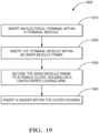
- FIG. 19 is a flowchart of an example method 1900 for assembling an electrical connector 100, comprising the steps of:
- connector assembly While the example presented herein is directed to an electrical connector assembly, alternative embodiments of the connector assembly may be envisioned that are configured to interconnect fiber optic cables, pneumatic tubes, hydraulic tubes, or a hybrid connector assembly having a combination of any of these types of conductors.
- 'one or more' includes a function being performed by one element, a function being performed by more than one element, e.g., in a distributed fashion, several functions being performed by one element, several functions being performed by several elements, or any combination of the above.
- the term “if' is, optionally, construed to mean “when” or “upon” or “in response to determining” or “in response to detecting,” depending on the context.
- the phrase “if it is determined” or “if [a stated condition or event] is detected” is, optionally, construed to mean “upon determining” or “in response to determining” or “upon detecting [the stated condition or event]” or “in response to detecting [the stated condition or event],” depending on the context.
Landscapes
- Connector Housings Or Holding Contact Members (AREA)
- Details Of Connecting Devices For Male And Female Coupling (AREA)
Abstract
Description
- This application is directed to a connector assembly with a flexible lock and an event driven wedge.
- Electrical connector assemblies having terminal module frames that are axially loaded into an outer connector housing requires additional clearance between the face of a flexible locking arm of the outer connector housing and the corresponding locking surface of an inner terminal module frame, thereby creating additional axial variation between the outer connector housing the inner terminal module frame, which in turn affects terminal-to-terminal contact overlap of the terminals in the female connector terminal modules and the terminals in a male connector or header pin in the connector assembly. Electrical connector assemblies having terminal modules that are laterally loaded into an outer connector housing reduce the clearance with respect to terminal-to-terminal contact overlap but increases the overall package size of the electrical connector assembly. Flexible locking arms are typically not reinforced so the retention force between the inner terminal module frame and the outer connector housing provided by the flexible locking arms is low.
- According to one or more aspects of the present disclosure, an electrical connector assembly includes a plurality of terminal modules, each configured to contain one or more electrical terminals connected to one or more electrical cables; an inner module frame in which the plurality of terminal modules is secured; and a female outer housing having a plurality of cantilevered locking arms with primary surfaces and secondary surfaces on inner sides of the locking arms configured to secure the inner module frame to the female outer housing. Latch surfaces of the inner module frame engage the primary surfaces when the inner module frame is inserted within the female outer housing. The female outer housing is configured to receive a header having side walls surrounding a plurality of mating electrical terminals. The locking arms define ramp features on outer sides of the locking arms configured to push the locking arms inwardly when the side walls contact the ramp features of the locking arms as the header is inserted within the outer housing, thereby engaging the secondary surfaces with the latch surfaces.
- In some aspects of the connector assembly described in the preceding paragraph, the secondary surfaces are arranged closer to free ends of the locking arms than the primary surfaces.
- In some aspects of the connector assembly described in any one of the preceding paragraphs, the latch surfaces are substantially parallel to the primary surfaces and nonparallel to the secondary surfaces.
- In some aspects of the connector assembly described in any one of the preceding paragraphs, the secondary surfaces are nonparallel with the primary surfaces.
- In some aspects of the connector assembly described in any one the preceding paragraphs, a first force applied to the latch surfaces when the primary surfaces engage the latch surfaces is less than a second force applied to the latch surfaces when the secondary surfaces engage the latch surfaces.
- In some aspects of the connector assembly described in any one of the preceding paragraphs, a magnitude of the first force is zero.
- In some aspects of the connector assembly described in any one the preceding paragraphs, the secondary surfaces are angled and configured to provide the second force on the latch surfaces due to a wedging interface between the secondary surfaces and edges of the latch surfaces when the side walls of the header are in contact with the ramp features.
- In some aspects of the connector assembly described in any one of the preceding paragraphs, a first clearance distance between the primary surfaces and the latch surfaces when the side walls of the header are not in contact with the ramp features is greater than a second clearance distance between the secondary surfaces and the latch surfaces when the side walls of the header are in contact with the ramp features.
- In some aspects of the connector assembly described in any one of the preceding paragraphs, the second clearance distance is less than 0.1 mm when the side walls are in contact with the ramp features.
- In some aspects of the connector assembly described in any one of the preceding paragraphs, the second clearance distance is 0 mm when the side walls are in contact with the ramp features.
- According to one or more aspects of the present disclosure, a method of assembling an electrical connector includes:
- inserting one or more electrical terminals connected to one or more electrical cables within a plurality of terminal modules;
- inserting the plurality of terminal modules within an inner module frame;
- securing the inner module frame to a female outer housing via a plurality of cantilevered locking arms having primary surfaces and secondary surfaces on inner sides of the locking arms. Latch surfaces of the inner module frame engage the primary surfaces when the inner module frame is inserted within the outer housing; and
- inserting a header having side walls surrounding a plurality of mating electrical terminals within the outer housing. The locking arms define ramp features on outer sides of the locking arms configured to push the locking arms inwardly when the side walls contact the ramp features of the locking arms as the header is inserted within the outer housing, thereby engaging the secondary surfaces with the latch surfaces of the inner module frame.
- In some aspects of the method described in the preceding paragraph, the method further includes applying a first force to the inner module frame via the locking arms when the primary surfaces engage the latch surfaces and applying a second force to the latch surfaces via the locking arms when the secondary surfaces engage the latch surfaces. The first force is less than the second force.
- In some aspects of the method described in any one of the preceding paragraphs, the secondary surfaces are angled and configured to provide the second force on the latch surfaces due to a wedging interface between the secondary surfaces and edges of the latch surfaces when the side walls of the header are in contact with the ramp features.
- In some aspects of the method described in any one of the preceding paragraphs, the secondary surfaces are angled and provide the second force on the latch surfaces due to a wedging interface between the secondary surfaces and edges of the latch surfaces when the side walls of the header are in contact with the ramp features.
- In some aspects of the method described in any one of the preceding paragraphs, a first clearance distance between the primary surfaces and the latch surfaces of the inner module frame when the side walls of the header are not in contact with the ramp features is greater than a second clearance distance between the secondary surfaces and the latch surfaces of the inner module frame when the side walls of the header are in contact with the ramp features.
- The present invention will now be described, by way of example with reference to the accompanying drawings, in which:
-
FIG. 1 illustrates an isometric view of an electrical connector assembly according to some embodiments; -
FIG. 2 illustrates an exploded view of the electrical connector assembly ofFIG.1 according to some embodiments; -
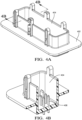
FIG. 3A illustrates an isometric top view of a connector header of the electrical connector assembly ofFIG. 1 according to some embodiments; -
FIG. 3B illustrates a cross-section view of the connector header ofFIG. 3A according to some embodiments; -
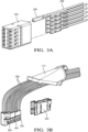
FIG. 4A illustrates an isometric view of a terminal module frame of the electrical connector assembly ofFIG. 1 according to some embodiments; -
FIG. 4B illustrates an isometric view of an inner terminal module frame of the electrical connector assembly ofFIG. 1 according to some embodiments; -
FIG. 5 illustrates a cross section view of an outer connector housing according to some embodiments; -
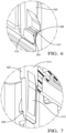
FIG. 6 illustrates a close-up view of a front face of a flexible locking arm of the outer connector housing ofFIG. 5 according to some embodiments; -
FIG. 7 illustrates a close-up view of a rear face of a flexible locking arm of the outer connector housing ofFIG. 5 according to some embodiments; -
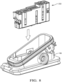
FIG. 8 illustrates an isometric view of the inner terminal module frame ofFIG. 4B containing as plurality of terminal modules being inserted into the outer connector housing ofFIG. 5 according to some embodiments; -
FIG. 9 illustrates a cross section view of the inner terminal module frame ofFIG. 4B being inserted into the outer connector housing ofFIG. 5 according to some embodiments; -
FIG. 10 illustrates a cross section view of the inner terminal module frame ofFIG. 4B fully inserted into the outer connector housing ofFIG. 5 according to some embodiments; -
FIG. 11 illustrates an isometric view of an outer housing subassembly containing the inner terminal module frame ofFIG. 4B fully inserted into the outer connector housing ofFIG. 5 according to some embodiments; -
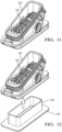
FIG. 12 illustrates an isometric view of the connector header ofFIG. 3A being inserted into the outer connector subassembly ofFIG. 11 according to some embodiments; -
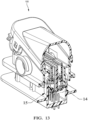
FIG. 13 illustrates a cross section view of the connector header ofFIG. 3A as the connector header is being inserted into the outer connector subassembly ofFIG. 11 according to some embodiments; -
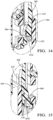
FIG. 14 illustrates a close-up view of the front face of a flexible locking arm ofFIG. 5 interfacing with the inner terminal module frame ofFIG. 4B as the connector header is being inserted into the outer connector subassembly according to some embodiments; -
FIG. 15 illustrates a close-up view of the rear face of a flexible locking arm ofFIG. 5 interfacing with a shroud wall of the connector header ofFIG. 3A as the connector header is being inserted into the outer connector subassembly according to some embodiments; -
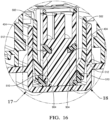
FIG. 16 illustrates a cross section view of the connector header ofFIG. 3A after the connector header is fully inserted into the outer connector subassembly ofFIG. 11 according to some embodiments; -
FIG. 17 illustrates a close-up view of the front face of a flexible locking arm ofFIG. 5 interfacing with the inner terminal module frame ofFIG. 4B after the connector header is fully inserted into the outer connector subassembly according to some embodiments; -
FIG. 18 illustrates a close-up view of the rear face of a flexible locking arm ofFIG. 5 interfacing with a shroud wall of the connector header ofFIG. 3A after the connector header is fully inserted into the outer connector subassembly according to some embodiments; and -
FIG. 19 is a flow chart of a method of assembling and electrical connector according to some embodiments. -
FIGs. 1 and2 illustrate a non-limiting example of an electrical connector assembly, hereafter referred to as theconnector 100. Theconnector 100 includes aharness connector 102 configured to contain a plurality of electrical terminals terminating electrical cables of a wiring harness as shown inFIG. 4A . Returning toFIG. 1 , theconnector 100 also includes aheader connector 104 containing a plurality of mating electrical terminals. Theheader connector 104 is configured to be mounted to a panel or bulkhead (not shown). - Returning now to
FIGs. 1 and2 , theharness connector 102 includes a femaleouter housing 106 having amating assist lever 108. As shown inFIG. 2 , the mating assistlever 108 is made of two piece that snap together to simplify the attachment of the mating assistlever 108 to the femaleouter housing 106. Theharness connector 102 also includes aterminal module 202, awire dress cover 110 configured to arrange the electrical cables of the wiring harness, and aseal 204 between thewire dress cover 110 and the femaleouter housing 106 to inhibit entry of environmental contaminants, such as dirt, dust, water, and other fluids into the femaleouter housing 106. - The
terminal module 202 includes aninner module frame 302 illustrated inFIGs. 3A and 3B which is configured to retain a number ofelectrical connector modules 304 containing theelectrical terminals 306 connected to theelectrical cables 308. Theinner module frame 302 also includes its own terminal cavities that are configured to contain coaxial terminals. Theterminal module 202 is placed within the femaleouter housing 106 to retain theterminals 306 within theharness connector 102. - As shown in
FIGs. 4A and 4B , theheader connector 104 includes ashroud 402 havingside walls 404 that surround the matingelectrical terminals 406. Theside walls 404 are received within theharness connector 102. Themating assist lever 108 is configured to help overcome the mechanical resistance of mating the plurality ofelectrical terminals 306 in theharness connector 102 to the plurality of matingelectrical terminals 406 in theheader connector 104. - As shown in
FIG. 5 , the femaleouter housing 106 defines a number of cantilevered flexible lockingarms 502 that hold theterminal module 202 within the femaleouter housing 106. As best shown inFIG. 6 , stop faces 504 oninner surfaces 506 of eachflexible locking arm 502 is separated into aprimary surface 508 and asecondary surface 510. As best shown inFIG 7 , the flexible lockingarms 502 also each have an outer wedge shapedramp feature 512 on theirouter surface 514. Thesecondary surfaces 510 are located at the ends of the lockingarms 502, i.e., thesecondary surfaces 510 are arranged closer to the free ends 516 of the lockingarms 502 than theprimary surfaces 508. - As illustrated in
FIG. 8 , theterminal module 202 is axially inserted into the femaleouter housing 106. When theterminal module 202 is inserted into female outer housing (beforeheader connector 104 engagement) as shown inFIG. 9 , theinner module frame 302 contacts aninner ramp feature 902 on theirouter surface 514 on theinner surfaces 506 of the flexible lockingarms 502 and pushes the flexible lockingarms 502 outwardly until alatch surface 904 on the inner module frame clear the stop faces 504. - As illustrated in
FIG. 10 , theprimary surface 508 of thestop face 504 of eachflexible locking arm 502 contacts anedge 1010 of thelatch surface 904 on theinner module frame 302 and theprimary surfaces 508 and apply a first force F1 to theinner module frame 302 that holds theterminal module 202 within the female outer housing as shown inFIG. 11 . Theprimary surfaces 510 are arranged substantially parallel to the latch surfaces 904. and the secondary surfaces are nonparallel to both the first surfaces and the latch surfaces. - As the
header connector 104 is inserted to the female outer housing as shown inFIGs 12 through 19 , theside walls 404 of theshroud 402 contact the outer wedge shapedramp feature 512 and push the flexible lockingarms 502 inwardly so that the angledsecondary surface 510 of thestop face 504 of eachflexible locking arm 502, rather than theprimary surface 508, contacts thelatch surface 904 on theinner module frame 302. Thesecondary surfaces 510 are nonparallel to both theprimary surfaces 508 and the latch surfaces 904. The angledsecondary surface 510 acts as a wedge and applies a second force F2 that pushes theinner module frame 302 toward theheader connector 104, thereby increasing the terminal overlap of theterminals 306 and themating terminals 406 and reducing the likelihood of relative movement between theterminals 306 and themating terminals 406 caused by vibration that may degrade the electrical performance of theconnector 100. - The second force F2 is greater than the first force F1. The first force F1 may have zero magnitude.
- There may be a first clearance distance between the
primary surfaces 508 and the latch surfaces 904 when theside walls 404 of theshroud 402 are not in contact with the outer wedge shaped ramp features 512. This first clearance distance is greater than a second clearance distance between thesecondary surfaces 510 and the latch surfaces 904 when theside walls 404 of theshroud 402 are in contact with the outer wedge shapedramp feature 512. The second clearance distance may be less than 0.1 mm when theside walls 404 are in contact with the outer wedge shapedramp feature 512 and is preferably 0 mm, meaning there is no clearance between thesecondary surfaces 510 and the latch surfaces 904. -
FIG. 19 is a flowchart of anexample method 1900 for assembling anelectrical connector 100, comprising the steps of: -
STEP 1910, INSERT AN ELECTRICAL TERMINAL WITHIN A TERMINAL MODULE, includes inserting one or moreelectrical terminals 306 connected to one or more electrical cables within a plurality ofterminal modules 304; -
STEP 1920, INSERT THE TERMINAL MODULE WITHIN AN INNER MODULE FRAME, includes inserting the plurality ofterminal modules 304 within aninner module frame 302; -
STEP 1930, SECURE THE INNER MODULE FRAME TO A FEMALE OUTER HOUSING VIA A CANTILEVERED LOCKING ARM, includes securing theinner module frame 302 to a femaleouter housing 106 via a plurality of cantilevered lockingarms 502 havingprimary surfaces 508 andsecondary surfaces 510 oninner surfaces 506 of the lockingarms 502. Latch surfaces 904 on theinner module frame 302 engage theprimary surfaces 508 when theinner module frame 302 is inserted within the femaleouter housing 106; and -
STEP 1940, INSERT A HEADER WITHIN THE OUTER HOUSING, includes inserting ashroud 402 of aheader connector 104 havingside walls 404 surrounding a plurality of matingelectrical terminals 406 within the femaleouter housing 106. The lockingarms 502 define ramp features 512 on theirouter surfaces 514 that are configured to push the lockingarms 502 inwardly when theside walls 404 contact the ramp features 512 of the lockingarms 502 as theshroud 402 is inserted within the femaleouter housing 106, thereby engaging thesecondary surfaces 510 with the latch surfaces 904 of theinner module frame 302. - The
connector 100 provides at least following benefits: - A reduction of the package size of the connector because the assembly process of inserting the inner module frame into the female outer housing may be accomplished using only axial movement of the inner module frame relative to the female outer housing;
- An improvement is terminal overlap distance between the terminals and the mating terminals due to the stepped primary and secondary surfaces on the flexible locking arm; and
- Reinforcement of the flexible locking arms by the male header shroud resulting in improved retention force of the inner module frame within the female outer housing.
- While the example presented herein is directed to an electrical connector assembly, alternative embodiments of the connector assembly may be envisioned that are configured to interconnect fiber optic cables, pneumatic tubes, hydraulic tubes, or a hybrid connector assembly having a combination of any of these types of conductors.
- While the invention has been described with reference to an exemplary embodiment(s), it will be understood by those skilled in the art that various changes may be made, and equivalents may be substituted for elements thereof without departing from the scope of the invention. In addition, many modifications may be made to adapt a particular situation or material to the teachings of the invention without departing from the essential scope thereof. Therefore, it is intended that the invention is not limited to the disclosed embodiment(s), but that the invention will include all embodiments falling within the scope of the appended claims.
- As used herein, 'one or more' includes a function being performed by one element, a function being performed by more than one element, e.g., in a distributed fashion, several functions being performed by one element, several functions being performed by several elements, or any combination of the above.
- It will also be understood that, although the terms first, second, etc. are, in some instances, used herein to describe various elements, these elements should not be limited by these terms. These terms are only used to distinguish one element from another. For example, a first contact could be termed a second contact, and, similarly, a second contact could be termed a first contact, without departing from the scope of the various described embodiments. The first contact and the second contact are both contacts, but they are not the same contact.
- The terminology used in the description of the various described embodiments herein is for the purpose of describing particular embodiments only and is not intended to be limiting. As used in the description of the various described embodiments and the appended claims, the singular forms "a", "an", and "the" are intended to include the plural forms as well, unless the context clearly indicates otherwise. It will also be understood that the term "and/or" as used herein refers to and encompasses any and all possible combinations of one or more of the associated listed items. It will be further understood that the terms "includes," "including," "comprises," and/or "comprising," when used in this specification, specify the presence of stated features, integers, steps, operations, elements, and/or components, but do not preclude the presence or addition of one or more other features, integers, steps, operations, elements, components, and/or groups thereof.
- As used herein, the term "if' is, optionally, construed to mean "when" or "upon" or "in response to determining" or "in response to detecting," depending on the context. Similarly, the phrase "if it is determined" or "if [a stated condition or event] is detected" is, optionally, construed to mean "upon determining" or "in response to determining" or "upon detecting [the stated condition or event]" or "in response to detecting [the stated condition or event]," depending on the context.
- Additionally, while terms of ordinance or orientation may be used herein these elements should not be limited by these terms. All terms of ordinance or orientation, unless stated otherwise, are used for purposes distinguishing one element from another, and do not denote any particular order, order of operations, direction or orientation unless stated otherwise.
Claims (15)
- An electrical connector assembly (100), comprising:a plurality of terminal modules (304), each configured to contain one or more electrical terminals (306) connected to one or more electrical cables (308);an inner module frame (302) in which the plurality of terminal modules (304) is secured; anda female outer housing (106) having a plurality of cantilevered locking arms (502) with primary surfaces (508) and secondary surfaces (510) on inner sides of the locking arms (502) configured to secure the inner module frame (302) to the female outer housing (106), wherein latch surfaces (904) of the inner module frame (302) engage the primary surfaces (508) when the inner module frame (302) is inserted within the female outer housing (106), wherein the female outer housing (106) is configured to receive a header having side walls (404) surrounding a plurality of mating electrical terminals (406), wherein the locking arms (502) define ramp features on outer sides of the locking arms (502) configured to push the locking arms (502) inwardly when the side walls (404) contact the ramp features of the locking arms (502) as the header is inserted within the outer housing (106), thereby engaging the secondary surfaces (510) with the latch surfaces (904).
- The electrical connector assembly (100) according to claim 1, wherein the secondary surfaces (510) are arranged closer to free ends (516) of the locking arms (502) than the primary surfaces (508).
- The electrical connector assembly (100) according to claim 1 or 2, wherein the latch surfaces (904) are substantially parallel to the primary surfaces (508) and nonparallel to the secondary surfaces (510).
- The electrical connector assembly (100) according to any one of the preceding claims, wherein the secondary surfaces (510) are nonparallel with the primary surfaces (508).
- The electrical connector assembly (100) according to any one of the preceding claims, wherein a first force applied to the latch surfaces (904) when the primary surfaces (508) engage the latch surfaces (904) is less than a second force applied to the latch surfaces (904) when the secondary surfaces (510) engage the latch surfaces (904).
- The electrical connector assembly (100) according to claim 5, wherein a magnitude of the first force is zero.
- The electrical connector assembly (100) according to claim 5 or 6, wherein the secondary surfaces (510) are angled and configured to provide the second force on the latch surfaces (904) due to a wedging interface between the secondary surfaces (510) and edges of the latch surfaces (904) when the side walls (404) of the header are in contact with the ramp features.
- The electrical connector assembly (100) according to any one of claims 5 to 7, wherein a first clearance distance between the primary surfaces (508) and the latch surfaces (904) when the side walls (404) of the header are not in contact with the ramp features is greater than a second clearance distance between the secondary surfaces (510) and the latch surfaces (904) when the side walls (404) of the header are in contact with the ramp features.
- The electrical connector assembly (100) according to claim 8, wherein the second clearance distance is less than 0.1 mm when the side walls (404) are in contact with the ramp features.
- The electrical connector assembly (100) according to claim 9, wherein the second clearance distance is 0 mm when the side walls (404) are in contact with the ramp features.
- A method (1900) of assembling an electrical connector (100), comprising:inserting one or more electrical terminals (306) connected to one or more electrical cables (308) within a plurality of terminal modules (304);inserting the plurality of terminal modules (304) within an inner module frame (302);securing the inner module frame (302) to a female outer housing (106) via a plurality of cantilevered locking arms (502) having primary surfaces (508) and secondary surfaces (510) on inner sides of the locking arms (502), wherein latch surfaces (904) of the inner module frame (302) engage the primary surfaces (508) when the inner module frame (302) is inserted within the outer housing (106); andinserting a header having side walls (404) surrounding a plurality of mating electrical terminals (306) (406) within the outer housing (106), wherein the locking arms (502) define ramp features on outer sides of the locking arms (502) configured to push the locking arms (502) inwardly when the side walls (404) contact the ramp features of the locking arms (502) as the header is inserted within the outer housing (106), thereby engaging the secondary surfaces (510) with the latch surfaces (904) of the inner module frame (302).
- The method (1900) according to claim 11, further comprising:applying a first force to the inner module frame (302) via the locking arms (502) when the primary surfaces (508) engage the latch surfaces (904); andapplying a second force to the latch surfaces (904) via the locking arms (502) when the secondary surfaces (510) engage the latch surfaces (904), wherein the first force is less than the second force.
- The method (1900) according to claim 12, wherein the secondary surfaces (510) are angled and configured to provide the second force on the latch surfaces (904) due to a wedging interface between the secondary surfaces (510) and edges of the latch surfaces (904) when the side walls (404) of the header are in contact with the ramp features.
- The method (1900) according to claim 12 or 13, wherein the secondary surfaces (510) are angled and provide the second force on the latch surfaces (904) due to a wedging interface between the secondary surfaces (510) and edges of the latch surfaces (904) when the side walls (404) of the header are in contact with the ramp features.
- The method (1900) according to any one of claims 12 to 14, wherein a first clearance distance between the primary surfaces (508) and the latch surfaces (904) of the inner module frame (302) when the side walls (404) of the header are not in contact with the ramp features is greater than a second clearance distance between the secondary surfaces (510) and the latch surfaces (904) of the inner module frame (302) when the side walls (404) of the header are in contact with the ramp features.
Applications Claiming Priority (1)
| Application Number | Priority Date | Filing Date | Title |
|---|---|---|---|
| US18/092,989 US12308568B2 (en) | 2023-01-04 | 2023-01-04 | Connector assembly with flexible lock and event driven wedge |
Publications (2)
| Publication Number | Publication Date |
|---|---|
| EP4398426A1 true EP4398426A1 (en) | 2024-07-10 |
| EP4398426B1 EP4398426B1 (en) | 2025-06-25 |
Family
ID=89119179
Family Applications (1)
| Application Number | Title | Priority Date | Filing Date |
|---|---|---|---|
| EP23214382.6A Active EP4398426B1 (en) | 2023-01-04 | 2023-12-05 | Connector assembly with flexible lock and event driven wedge |
Country Status (3)
| Country | Link |
|---|---|
| US (1) | US12308568B2 (en) |
| EP (1) | EP4398426B1 (en) |
| CN (1) | CN118299846A (en) |
Citations (2)
| Publication number | Priority date | Publication date | Assignee | Title |
|---|---|---|---|---|
| US9847601B2 (en) * | 2015-08-31 | 2017-12-19 | Delphi International Operations Luxenbourg S.A.R.L. | Electrical connector |
| DE112014003938B4 (en) * | 2013-08-30 | 2018-02-08 | Yazaki Corporation | Interconnects |
Family Cites Families (12)
| Publication number | Priority date | Publication date | Assignee | Title |
|---|---|---|---|---|
| US6171146B1 (en) * | 1998-02-19 | 2001-01-09 | Delphi Technologies, Inc. | Repair method for dual lock multi-row electrical connector system |
| US6332789B1 (en) * | 1999-05-31 | 2001-12-25 | Yazaki Corporation | Connector supporting mechanism |
| US6558176B1 (en) * | 2002-03-07 | 2003-05-06 | Tyco Electronics Corp. | Mate assist assembly for connecting electrical contacts |
| US6960090B2 (en) * | 2002-08-07 | 2005-11-01 | Tyco Electronics Amp Gmbh | Plug connector arrangement with latching actuation slide means |
| DE102004013476A1 (en) * | 2003-04-16 | 2004-11-04 | Tyco Electronics Amp Gmbh | Electrical connector device for motor vehicle, has lever with clamping section which engages with complementary clamping section on housing side when lever is in coupling position |
| US7645151B2 (en) * | 2007-03-22 | 2010-01-12 | Tyco Electronics Corporation | Shunted electrical connector and shunt therefore |
| JP4988430B2 (en) * | 2007-05-18 | 2012-08-01 | 三菱電線工業株式会社 | Lever type connector |
| JP2009259442A (en) * | 2008-04-14 | 2009-11-05 | Molex Inc | Connector |
| DE102009056184B4 (en) * | 2008-12-22 | 2012-10-04 | Sumitomo Wiring Systems, Ltd. | Interconnects |
| JP5961493B2 (en) * | 2012-09-04 | 2016-08-02 | 矢崎総業株式会社 | Connector device |
| JP2014165027A (en) * | 2013-02-26 | 2014-09-08 | Sumitomo Wiring Syst Ltd | Connector with booster mechanism |
| US9142916B2 (en) * | 2013-03-15 | 2015-09-22 | Tyco Electronics Corporation | Connector assembly with receptacle carriers |
-
2023
- 2023-01-04 US US18/092,989 patent/US12308568B2/en active Active
- 2023-12-05 EP EP23214382.6A patent/EP4398426B1/en active Active
- 2023-12-15 CN CN202311739673.4A patent/CN118299846A/en active Pending
Patent Citations (2)
| Publication number | Priority date | Publication date | Assignee | Title |
|---|---|---|---|---|
| DE112014003938B4 (en) * | 2013-08-30 | 2018-02-08 | Yazaki Corporation | Interconnects |
| US9847601B2 (en) * | 2015-08-31 | 2017-12-19 | Delphi International Operations Luxenbourg S.A.R.L. | Electrical connector |
Also Published As
| Publication number | Publication date |
|---|---|
| US12308568B2 (en) | 2025-05-20 |
| EP4398426B1 (en) | 2025-06-25 |
| US20240222907A1 (en) | 2024-07-04 |
| CN118299846A (en) | 2024-07-05 |
Similar Documents
| Publication | Publication Date | Title |
|---|---|---|
| US10374328B2 (en) | Terminal fitting with hood | |
| US6840789B2 (en) | Connector and a method of assembling it | |
| EP0384577A2 (en) | Electrical connector for fuel injector and terminals therefor | |
| EP3155695B1 (en) | Cable strain relief | |
| US11515660B2 (en) | Electrical connector assembly with retaining device | |
| KR20140139577A (en) | Structure and method for assembling connector | |
| CN110313110B (en) | Electrical Terminals and Connector Assemblies | |
| CN110401073B (en) | Electrical shielding member for electrical connector assembly | |
| CN109256642B (en) | Connector backshell assembly | |
| EP4297193A1 (en) | Electrical connector assembly with flexible and rigid terminal locking features | |
| US7011539B1 (en) | Seal for an electrical connector | |
| EP4398426B1 (en) | Connector assembly with flexible lock and event driven wedge | |
| US12562520B2 (en) | Connector assembly with terminal position assurance and blocking feature | |
| CN110383595A (en) | Connector | |
| US11450985B2 (en) | Connector with integrated seal retainer and secondary terminal lock | |
| WO2013153089A1 (en) | Electrical contact device, in particular electrical socket contact device | |
| US7044766B2 (en) | Automotive electrical connection box and method of assembling thereof | |
| EP4542779A1 (en) | Connector assembly with device for adapting a terminal to a connector body and method of assembling same | |
| EP4734293A1 (en) | Wire dress cover for electrical connector | |
| US12266885B2 (en) | Seal retainer with seal expansion compensation features | |
| US20250309578A1 (en) | Interlocking connector design for electrical connectors | |
| US20240022017A1 (en) | Electrical connector for connecting high voltage power cable including electrical conductor to electrical terminal | |
| US20250316928A1 (en) | Connector having retention feature for lever and slide mating assist mechanism | |
| CN117276944A (en) | Electrical connector assembly with flexible and rigid terminal locking features | |
| CN117438813A (en) | Connector assembly with terminal position assurance and blocking features |
Legal Events
| Date | Code | Title | Description |
|---|---|---|---|
| PUAI | Public reference made under article 153(3) epc to a published international application that has entered the european phase |
Free format text: ORIGINAL CODE: 0009012 |
|
| STAA | Information on the status of an ep patent application or granted ep patent |
Free format text: STATUS: THE APPLICATION HAS BEEN PUBLISHED |
|
| AK | Designated contracting states |
Kind code of ref document: A1 Designated state(s): AL AT BE BG CH CY CZ DE DK EE ES FI FR GB GR HR HU IE IS IT LI LT LU LV MC ME MK MT NL NO PL PT RO RS SE SI SK SM TR |
|
| STAA | Information on the status of an ep patent application or granted ep patent |
Free format text: STATUS: REQUEST FOR EXAMINATION WAS MADE |
|
| RAP3 | Party data changed (applicant data changed or rights of an application transferred) |
Owner name: APTIV TECHNOLOGIES AG |
|
| 17P | Request for examination filed |
Effective date: 20240828 |
|
| RBV | Designated contracting states (corrected) |
Designated state(s): AL AT BE BG CH CY CZ DE DK EE ES FI FR GB GR HR HU IE IS IT LI LT LU LV MC ME MK MT NL NO PL PT RO RS SE SI SK SM TR |
|
| GRAP | Despatch of communication of intention to grant a patent |
Free format text: ORIGINAL CODE: EPIDOSNIGR1 |
|
| STAA | Information on the status of an ep patent application or granted ep patent |
Free format text: STATUS: GRANT OF PATENT IS INTENDED |
|
| RIC1 | Information provided on ipc code assigned before grant |
Ipc: H01R 13/518 20060101ALN20250113BHEP Ipc: H01R 13/514 20060101ALI20250113BHEP Ipc: H01R 13/506 20060101AFI20250113BHEP |
|
| INTG | Intention to grant announced |
Effective date: 20250127 |
|
| GRAS | Grant fee paid |
Free format text: ORIGINAL CODE: EPIDOSNIGR3 |
|
| GRAA | (expected) grant |
Free format text: ORIGINAL CODE: 0009210 |
|
| STAA | Information on the status of an ep patent application or granted ep patent |
Free format text: STATUS: THE PATENT HAS BEEN GRANTED |
|
| AK | Designated contracting states |
Kind code of ref document: B1 Designated state(s): AL AT BE BG CH CY CZ DE DK EE ES FI FR GB GR HR HU IE IS IT LI LT LU LV MC ME MK MT NL NO PL PT RO RS SE SI SK SM TR |
|
| REG | Reference to a national code |
Ref country code: GB Ref legal event code: FG4D |
|
| REG | Reference to a national code |
Ref country code: CH Ref legal event code: EP |
|
| P01 | Opt-out of the competence of the unified patent court (upc) registered |
Free format text: CASE NUMBER: APP_25283/2025 Effective date: 20250527 |
|
| REG | Reference to a national code |
Ref country code: DE Ref legal event code: R096 Ref document number: 602023004309 Country of ref document: DE |
|
| REG | Reference to a national code |
Ref country code: CH Ref legal event code: EP |
|
| REG | Reference to a national code |
Ref country code: IE Ref legal event code: FG4D |
|
| PG25 | Lapsed in a contracting state [announced via postgrant information from national office to epo] |
Ref country code: FI Free format text: LAPSE BECAUSE OF FAILURE TO SUBMIT A TRANSLATION OF THE DESCRIPTION OR TO PAY THE FEE WITHIN THE PRESCRIBED TIME-LIMIT Effective date: 20250625 |
|
| REG | Reference to a national code |
Ref country code: LT Ref legal event code: MG9D |
|
| PG25 | Lapsed in a contracting state [announced via postgrant information from national office to epo] |
Ref country code: NO Free format text: LAPSE BECAUSE OF FAILURE TO SUBMIT A TRANSLATION OF THE DESCRIPTION OR TO PAY THE FEE WITHIN THE PRESCRIBED TIME-LIMIT Effective date: 20250925 Ref country code: GR Free format text: LAPSE BECAUSE OF FAILURE TO SUBMIT A TRANSLATION OF THE DESCRIPTION OR TO PAY THE FEE WITHIN THE PRESCRIBED TIME-LIMIT Effective date: 20250926 |
|
| PG25 | Lapsed in a contracting state [announced via postgrant information from national office to epo] |
Ref country code: BG Free format text: LAPSE BECAUSE OF FAILURE TO SUBMIT A TRANSLATION OF THE DESCRIPTION OR TO PAY THE FEE WITHIN THE PRESCRIBED TIME-LIMIT Effective date: 20250625 |
|
| PG25 | Lapsed in a contracting state [announced via postgrant information from national office to epo] |
Ref country code: HR Free format text: LAPSE BECAUSE OF FAILURE TO SUBMIT A TRANSLATION OF THE DESCRIPTION OR TO PAY THE FEE WITHIN THE PRESCRIBED TIME-LIMIT Effective date: 20250625 |
|
| PG25 | Lapsed in a contracting state [announced via postgrant information from national office to epo] |
Ref country code: RS Free format text: LAPSE BECAUSE OF FAILURE TO SUBMIT A TRANSLATION OF THE DESCRIPTION OR TO PAY THE FEE WITHIN THE PRESCRIBED TIME-LIMIT Effective date: 20250925 |
|
| PG25 | Lapsed in a contracting state [announced via postgrant information from national office to epo] |
Ref country code: LV Free format text: LAPSE BECAUSE OF FAILURE TO SUBMIT A TRANSLATION OF THE DESCRIPTION OR TO PAY THE FEE WITHIN THE PRESCRIBED TIME-LIMIT Effective date: 20250625 |
|
| REG | Reference to a national code |
Ref country code: NL Ref legal event code: MP Effective date: 20250625 |
|
| PG25 | Lapsed in a contracting state [announced via postgrant information from national office to epo] |
Ref country code: NL Free format text: LAPSE BECAUSE OF FAILURE TO SUBMIT A TRANSLATION OF THE DESCRIPTION OR TO PAY THE FEE WITHIN THE PRESCRIBED TIME-LIMIT Effective date: 20250625 |
|
| PG25 | Lapsed in a contracting state [announced via postgrant information from national office to epo] |
Ref country code: PT Free format text: LAPSE BECAUSE OF FAILURE TO SUBMIT A TRANSLATION OF THE DESCRIPTION OR TO PAY THE FEE WITHIN THE PRESCRIBED TIME-LIMIT Effective date: 20251027 |
|
| REG | Reference to a national code |
Ref country code: AT Ref legal event code: MK05 Ref document number: 1807586 Country of ref document: AT Kind code of ref document: T Effective date: 20250625 |
|
| PG25 | Lapsed in a contracting state [announced via postgrant information from national office to epo] |
Ref country code: IS Free format text: LAPSE BECAUSE OF FAILURE TO SUBMIT A TRANSLATION OF THE DESCRIPTION OR TO PAY THE FEE WITHIN THE PRESCRIBED TIME-LIMIT Effective date: 20251025 |
|
| PGFP | Annual fee paid to national office [announced via postgrant information from national office to epo] |
Ref country code: DE Payment date: 20251117 Year of fee payment: 3 |
|
| PG25 | Lapsed in a contracting state [announced via postgrant information from national office to epo] |
Ref country code: AT Free format text: LAPSE BECAUSE OF FAILURE TO SUBMIT A TRANSLATION OF THE DESCRIPTION OR TO PAY THE FEE WITHIN THE PRESCRIBED TIME-LIMIT Effective date: 20250625 Ref country code: SM Free format text: LAPSE BECAUSE OF FAILURE TO SUBMIT A TRANSLATION OF THE DESCRIPTION OR TO PAY THE FEE WITHIN THE PRESCRIBED TIME-LIMIT Effective date: 20250625 |
|
| PGFP | Annual fee paid to national office [announced via postgrant information from national office to epo] |
Ref country code: FR Payment date: 20251112 Year of fee payment: 3 |
|
| PG25 | Lapsed in a contracting state [announced via postgrant information from national office to epo] |
Ref country code: CZ Free format text: LAPSE BECAUSE OF FAILURE TO SUBMIT A TRANSLATION OF THE DESCRIPTION OR TO PAY THE FEE WITHIN THE PRESCRIBED TIME-LIMIT Effective date: 20250625 |
|
| PG25 | Lapsed in a contracting state [announced via postgrant information from national office to epo] |
Ref country code: PL Free format text: LAPSE BECAUSE OF FAILURE TO SUBMIT A TRANSLATION OF THE DESCRIPTION OR TO PAY THE FEE WITHIN THE PRESCRIBED TIME-LIMIT Effective date: 20250625 |
|
| PG25 | Lapsed in a contracting state [announced via postgrant information from national office to epo] |
Ref country code: EE Free format text: LAPSE BECAUSE OF FAILURE TO SUBMIT A TRANSLATION OF THE DESCRIPTION OR TO PAY THE FEE WITHIN THE PRESCRIBED TIME-LIMIT Effective date: 20250625 |
|
| PG25 | Lapsed in a contracting state [announced via postgrant information from national office to epo] |
Ref country code: SK Free format text: LAPSE BECAUSE OF FAILURE TO SUBMIT A TRANSLATION OF THE DESCRIPTION OR TO PAY THE FEE WITHIN THE PRESCRIBED TIME-LIMIT Effective date: 20250625 |
|
| PG25 | Lapsed in a contracting state [announced via postgrant information from national office to epo] |
Ref country code: ES Free format text: LAPSE BECAUSE OF FAILURE TO SUBMIT A TRANSLATION OF THE DESCRIPTION OR TO PAY THE FEE WITHIN THE PRESCRIBED TIME-LIMIT Effective date: 20250625 |
|
| PG25 | Lapsed in a contracting state [announced via postgrant information from national office to epo] |
Ref country code: RO Free format text: LAPSE BECAUSE OF FAILURE TO SUBMIT A TRANSLATION OF THE DESCRIPTION OR TO PAY THE FEE WITHIN THE PRESCRIBED TIME-LIMIT Effective date: 20250625 |
|
| PG25 | Lapsed in a contracting state [announced via postgrant information from national office to epo] |
Ref country code: DK Free format text: LAPSE BECAUSE OF FAILURE TO SUBMIT A TRANSLATION OF THE DESCRIPTION OR TO PAY THE FEE WITHIN THE PRESCRIBED TIME-LIMIT Effective date: 20250625 |
|
| PG25 | Lapsed in a contracting state [announced via postgrant information from national office to epo] |
Ref country code: IT Free format text: LAPSE BECAUSE OF FAILURE TO SUBMIT A TRANSLATION OF THE DESCRIPTION OR TO PAY THE FEE WITHIN THE PRESCRIBED TIME-LIMIT Effective date: 20250625 |
|
| PLBE | No opposition filed within time limit |
Free format text: ORIGINAL CODE: 0009261 |
|
| STAA | Information on the status of an ep patent application or granted ep patent |
Free format text: STATUS: NO OPPOSITION FILED WITHIN TIME LIMIT |
|
| REG | Reference to a national code |
Ref country code: CH Ref legal event code: L10 Free format text: ST27 STATUS EVENT CODE: U-0-0-L10-L00 (AS PROVIDED BY THE NATIONAL OFFICE) Effective date: 20260507 |