EP4398409A1 - Lead supply system and control method therefor - Google Patents
Lead supply system and control method therefor Download PDFInfo
- Publication number
- EP4398409A1 EP4398409A1 EP22864974.5A EP22864974A EP4398409A1 EP 4398409 A1 EP4398409 A1 EP 4398409A1 EP 22864974 A EP22864974 A EP 22864974A EP 4398409 A1 EP4398409 A1 EP 4398409A1
- Authority
- EP
- European Patent Office
- Prior art keywords
- lead
- seating part
- supply
- supply system
- vision sensor
- Prior art date
- Legal status (The legal status is an assumption and is not a legal conclusion. Google has not performed a legal analysis and makes no representation as to the accuracy of the status listed.)
- Pending
Links
Images


Classifications
-
- H—ELECTRICITY
- H01—ELECTRIC ELEMENTS
- H01M—PROCESSES OR MEANS, e.g. BATTERIES, FOR THE DIRECT CONVERSION OF CHEMICAL ENERGY INTO ELECTRICAL ENERGY
- H01M10/00—Secondary cells; Manufacture thereof
- H01M10/04—Construction or manufacture in general
- H01M10/0404—Machines for assembling batteries
-
- B—PERFORMING OPERATIONS; TRANSPORTING
- B23—MACHINE TOOLS; METAL-WORKING NOT OTHERWISE PROVIDED FOR
- B23Q—DETAILS, COMPONENTS, OR ACCESSORIES FOR MACHINE TOOLS, e.g. ARRANGEMENTS FOR COPYING OR CONTROLLING; MACHINE TOOLS IN GENERAL CHARACTERISED BY THE CONSTRUCTION OF PARTICULAR DETAILS OR COMPONENTS; COMBINATIONS OR ASSOCIATIONS OF METAL-WORKING MACHINES, NOT DIRECTED TO A PARTICULAR RESULT
- B23Q7/00—Arrangements for handling work specially combined with or arranged in, or specially adapted for use in connection with, machine tools, e.g. for conveying, loading, positioning, discharging, sorting
- B23Q7/04—Arrangements for handling work specially combined with or arranged in, or specially adapted for use in connection with, machine tools, e.g. for conveying, loading, positioning, discharging, sorting by means of grippers
-
- H—ELECTRICITY
- H01—ELECTRIC ELEMENTS
- H01M—PROCESSES OR MEANS, e.g. BATTERIES, FOR THE DIRECT CONVERSION OF CHEMICAL ENERGY INTO ELECTRICAL ENERGY
- H01M10/00—Secondary cells; Manufacture thereof
- H01M10/04—Construction or manufacture in general
- H01M10/0404—Machines for assembling batteries
- H01M10/0409—Machines for assembling batteries for cells with wound electrodes
-
- H—ELECTRICITY
- H01—ELECTRIC ELEMENTS
- H01M—PROCESSES OR MEANS, e.g. BATTERIES, FOR THE DIRECT CONVERSION OF CHEMICAL ENERGY INTO ELECTRICAL ENERGY
- H01M50/00—Constructional details or processes of manufacture of the non-active parts of electrochemical cells other than fuel cells, e.g. hybrid cells
- H01M50/50—Current conducting connections for cells or batteries
- H01M50/531—Electrode connections inside a battery casing
- H01M50/536—Electrode connections inside a battery casing characterised by the method of fixing the leads to the electrodes, e.g. by welding
-
- Y—GENERAL TAGGING OF NEW TECHNOLOGICAL DEVELOPMENTS; GENERAL TAGGING OF CROSS-SECTIONAL TECHNOLOGIES SPANNING OVER SEVERAL SECTIONS OF THE IPC; TECHNICAL SUBJECTS COVERED BY FORMER USPC CROSS-REFERENCE ART COLLECTIONS [XRACs] AND DIGESTS
- Y02—TECHNOLOGIES OR APPLICATIONS FOR MITIGATION OR ADAPTATION AGAINST CLIMATE CHANGE
- Y02E—REDUCTION OF GREENHOUSE GAS [GHG] EMISSIONS, RELATED TO ENERGY GENERATION, TRANSMISSION OR DISTRIBUTION
- Y02E60/00—Enabling technologies; Technologies with a potential or indirect contribution to GHG emissions mitigation
- Y02E60/10—Energy storage using batteries
-
- Y—GENERAL TAGGING OF NEW TECHNOLOGICAL DEVELOPMENTS; GENERAL TAGGING OF CROSS-SECTIONAL TECHNOLOGIES SPANNING OVER SEVERAL SECTIONS OF THE IPC; TECHNICAL SUBJECTS COVERED BY FORMER USPC CROSS-REFERENCE ART COLLECTIONS [XRACs] AND DIGESTS
- Y02—TECHNOLOGIES OR APPLICATIONS FOR MITIGATION OR ADAPTATION AGAINST CLIMATE CHANGE
- Y02P—CLIMATE CHANGE MITIGATION TECHNOLOGIES IN THE PRODUCTION OR PROCESSING OF GOODS
- Y02P70/00—Climate change mitigation technologies in the production process for final industrial or consumer products
- Y02P70/50—Manufacturing or production processes characterised by the final manufactured product
Definitions
- a lithium-based oxide and a carbon material are mainly used as a positive electrode active material and a negative electrode active material, respectively.
- the lithium secondary battery is provided with an electrode assembly, in which a plurality of electrodes coated respectively with the electrode active materials are disposed with a separator therebetween, and an exterior material which seals and accommodates the electrode assembly together with an electrolyte.
- An object of the present invention for solving the above problems is to provide a lead supply system, which automatically accurately aligns the lead so as to be connected to an electrode tab, and a method for controlling the lead supply system.
- a lead supply system may supply the lead so as to be connected to an electrode tab.
- the lead supply system may include: a seating part on which the lead is seated; a vision sensor that photographs the lead at an upper side of the seating part; an alignment mechanism that adjusts the seating part so as to align the lead on the basis of vision data photographed by the vision sensor; and a supply device that picks up the lead from the seating part so as to supply the lead to a position at which the lead is connected to the electrode tab.
- the lead supply system may further include a collecting box in which the lead is collected by the supply device when the lead is determined as a defect or inappropriateness on the basis of the vision data.
- the alignment mechanism may include a rotation motor, which is disposed below the seating part and rotates the seating part around a vertical axis, and an orthogonal robot which moves the rotation motor horizontally in first and second directions perpendicularly crossing each other.
- the supply device may include a gripper that holds the lead, and an orthogonal robot that moves the gripper in a second direction perpendicularly crossing the first direction and in a vertical direction.
- the lead supply system may further include a loading device that loads the lead on the seating part when the seating part is disposed at the standby position.
- the loading device may include an adsorption part that adsorbs the lead at an upper side, an elevation actuator that elevates the adsorption part, and a uniaxial actuator that moves the elevation actuator horizontally.
- the lead supply system may further include at least one of an overhead light unit, which emits light onto the lead from above the seating part, or a backlight unit provided in the seating part or disposed below the seating part.
- a method for controlling a lead supply system may include: a loading process of loading the lead on a seating part; a sensing process of photographing the lead on the seating part by a vision sensor; an alignment process of adjusting the seating part to align the lead on the basis of vision data photographed by the vision sensor; and a supply process of picking up the lead from the seating part to move the lead to a position at which the lead is connected to the electrode tab.
- the method may further include a collection process of picking up and collecting the lead when the lead is determined as a defect or inappropriateness on the basis of the vision data.
- the supply process may include picking up the lead seated on the seating part by a gripper, and moving the gripper horizontally in a second direction perpendicularly crossing to the first direction.
- the sensing process may be performed in a state in which light is emitted toward the lead.
- the alignment of the lead may be automatically performed without stopping the equipment. Accordingly, the productivity of the electrode assembly may increase.
- the lead When the lead is determined as a defect or inappropriateness on the basis of the vision data photographed by the vision sensor, the lead may be collected but not supplied. Accordingly, the quality of the electrode assembly may be further improved.
- FIG. 2 is a schematic diagram of a lead supply system according to an embodiment of the present invention.
- a direction parallel to an X-axis in FIG. 2 is called a first direction
- a direction parallel to a Y-axis is called a second direction
- a Z-axis is parallel to a vertical direction and thus, the first direction and the second direction may be horizontal directions perpendicularly crossing each other.
- a lead supply system 100 may include a seating part 150 on which a lead 30 (see FIG. 6 ) is seated, a vision sensor 140 disposed above the seating part 150, an alignment mechanism 151 that adjusts the seating part 150 so as to align the lead 30, and a supply device 170 that picks up the lead 30 from the seating part 150 so as to supply the lead to a preset position.
- the lead supply system 100 may further include a loading device 120 that loads the lead 30 on the seating part 150, and a supply buffer 110 that supplies the lead 30 to the loading device 120.
- the supply buffer 110 may sequentially supply the lead 30 manufactured in a previous process.
- the lead 30 may be provided in a state in which an insulation film for post-sealing with a pouch type battery case (not shown) is attached to a portion of a circumference of the lead 30.
- the supply buffer 110 may include a table 111 on which the lead 30 is seated, and a uniaxial actuator 112 that moves the table 111.
- the table 111 may be horizontally provided, and at least one lead 30 may be seated on a top surface of the table 111.
- the uniaxial actuator 112 may move the table 111 horizontally in the second direction.
- the uniaxial actuator 112 may include a base 112a coupled to a lower side of the table 111, and a guide 112b that guides movement of the base 112a and extends in the second direction.
- the table 111 may move in the second direction together with the base 112a.
- the detailed configuration and operation of the uniaxial actuator 112 are the well-known art and thus, the detailed description thereof will be omitted.
- the table 111 may reciprocate, by the uniaxial actuator 112, between an initial position at which the lead 30 is seated, and a supply position spaced apart from the initial position in the second direction.
- the supply position may be below the loading device 120 to be described later.
- FIG. 2 illustrates a state in which the table 111 is disposed at the supply position.
- the lead 30 may be seated on the table 111, and when the table 111, on which the lead 30 is seated, moves to the supply position by the uniaxial actuator 112, the loading device 120 may pick up the lead 30 seated on the table 111 so as to load the lead 30 on the seating part 150.
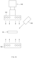
- the loading device 120 may include an adsorption part 121 that adsorbs the lead 30 at an upper side, an elevation actuator 122 that elevates the adsorption part 121, and a uniaxial actuator 123 that moves the elevation actuator 122.
- the adsorption part 121 may vacuum-adsorb the lead 30 on the table 111 of the supply buffer 110.
- the adsorption part 121 may include a close-contact part 121a in close contact with a top surface of the lead 30, and a support plate 121b on which the close-contact part 121a is suspended and supported.
- the close-contact part 121a may be communicated with a flexible pipe connected to a pump (not shown) that generates negative pressure.
- the elevation actuator 122 may elevate the adsorption part 121 in a vertical direction.
- the elevation actuator 122 may be connected to the adsorption part 121, more particularly to the support plate 121b.
- the adsorption part 121 may move horizontally in the first direction together with the elevation actuator 122.
- the adsorption part 121 may pick up the lead 30 from the table 111 of the supply buffer 110 and move in the first direction by the uniaxial actuator 123 so as to load the lead on the seating part 150.
- the support frame 130 may include a frame body 131 that supports the uniaxial actuator 123 of the loading device 120, and a pillar 132 that supports the horizontal frame body 131.
- the frame body 131 may be elongated in a direction parallel to the uniaxial actuator 123 of the loading device 120, i.e., in the first direction.
- the pillar 132 may be provided in plurality so as to stably support the frame body 131.
- the supply buffer 110 may be disposed to pass below the frame body 131.
- the adsorption part 121 and the elevation actuator 122 of the loading device 120 may be disposed at one side in a width direction of the frame body 131.
- the rotation motor 152 may be disposed below the seating part 150 and connected to the seating part 150.
- the rotation motor 152 may precisely adjust an angle of the seating part 150.
- the rotation motor 152 may be a servo motor.
- the seating part 150 may move, by the alignment mechanism 151, between a standby position (see FIG. 6 ) disposed below the vision sensor 140, and a supply position (see FIG. 7 ) spaced apart from the standby position in the first direction. That is, the alignment mechanism 151, more particularly the orthogonal robot 153, may reciprocate the seating part 150 between the standby position and the supply position.
- FIG. 2 illustrates a state in which the seating part 150 is disposed at the standby position.
- the vision sensor 140 may photograph the lead 30 at an upper side of the seating part 150.
- the vision sensor 140 may be disposed above the seating part 150 that is the standby position.
- the vision sensor 140 may include a camera.
- the gripper 171 may include a pair of holding parts spaced apart from each other in an upward-downward direction, and an actuator that changes a distance between the pair of holding parts.
- the lead 30 may be held between the pair of holding parts.
- the orthogonal robot 172 may include a first guide 172a that guides movement of the gripper 171 and is elongated in the second direction, and a second guide 172b that guides movement of the first guide 172a and is elongated in the vertical direction.
- the orthogonal robot 172 may further include a third guide 172c that guides movement of the second guide 172b and is elongated in the second direction.
- the orthogonal robot 172 may move the gripper 171 in the second direction and in the vertical direction.
- the orthogonal robot 172 may move the gripper 171 in the second direction so that the lead 30 on the seating part 150 is inserted between the pair of holding parts of the gripper 171.
- a groove that prevents an interference to the gripper 171 may be defined in the seating part 150.
- the orthogonal robot 172 may allow the gripper 171 holding the lead 30 to ascend so as to pick up the lead 30 from the seating part 150. In a state in which the gripper 171 picks up the lead 30, the orthogonal robot 172 may allow the gripper 171 to move and descend in the second direction so as to supply the lead 30 to the position at which the lead 30 is connected to the electrode tab 20 (see FIG. 9 ).
- the lead supply system 100 may further include a controller 190.
- the controller 190 may include at least one processor.
- the controller 190 may control the supply buffer 110, the loading device 120, and the supply device 170.
- the one lead 30 when one lead 30 is below a predetermined specification or detected to be broken, the one lead 30 may be determined as a defect.
- the controller 190 may analyze the vision data to determine the material of the lead 30 on the basis of the color property (e.g., chroma) of the lead 130, and may determine whether the material of the lead 30 matches polarity information of the electrode tab 20.
- the electrode tab 20 of a negative electrode may match the lead 30 having a nickel or copper material
- the electrode tab 20 of a positive electrode may match the lead 30 including an aluminum material.
- the controller 190 may control the supply device 170 to collect the lead 30 in the collecting box 160. In contrast, when the lead 30 is determined to be normal, the controller 190 may control the supply device 170 to supply the lead 30 to the position at which the lead 30 is connected to the electrode tab 20.
- FIG. 4 is a flowchart of a method for controlling a lead supply system according to an embodiment of the present invention.
- FIGS. 5 to 9 are views for explaining operations of the lead supply system according to an embodiment of the present invention.
- the controller 190 may analyze the vision data photographed in the previous sensing process (S20) to generate a control command for aligning the lead 30 at a predetermined position and deliver the control command to the alignment mechanism 151.
- the alignment mechanism 151 may move the seating part 150 in the horizontal direction, and may rotate the seating part 150 at a predetermined angle around a vertical axis.
- the seating part 150 may rotate at the predetermined angle by the rotation motor 152 and move by the orthogonal robot 153 in the first direction and in the second direction.
- the collection process (S80) may be performed. That is, the collection process (S80) may be a process of picking up and collecting the lead 30 when the lead 30 is determined as a defect and/or inappropriateness on the basis of the vision data photographed by the vision sensor 40.
- Electrode assembly 20 Electrode tab 30: Lead 100: Lead supply system 110: Supply buffer 120: Loading device 130: Support frame 140: Vision sensor 150: Seating part 151: Alignment mechanism 152: rotation motor 153: Orthogonal robot 160: Collecting box 170: Supply device 171: Gripper 172: Orthogonal robot 181: Overhead light unit 182: Backlight unit 183: Concentrative light unit 190; Controller
Landscapes
- Engineering & Computer Science (AREA)
- Chemical & Material Sciences (AREA)
- Chemical Kinetics & Catalysis (AREA)
- Electrochemistry (AREA)
- General Chemical & Material Sciences (AREA)
- Manufacturing & Machinery (AREA)
- Mechanical Engineering (AREA)
- Supply And Installment Of Electrical Components (AREA)
- Connection Of Batteries Or Terminals (AREA)
Abstract
Description
- The present application claims the benefit of the priority of
Korean Patent Application No. 10-2021-0117116, filed on September 02, 2021 - The present invention relates to a lead supply system and a method for controlling the same, and more particularly, to a lead supply system, which supplies a lead so as to be connected to an electrode tab provided in a cell, and a method for controlling the lead supply system.
- In general, secondary batteries refer to batteries that are chargeable and dischargeable unlike non-rechargeable primary batteries, and are widely used in electronic devices such as mobile phones, notebook computers, and camcorders, or electric vehicles, etc. In particular, a lithium secondary battery has a larger capacity and a higher energy density per unit weight than a nickel-cadmium battery or a nickel-hydrogen battery, and thus utilization thereof is on a rapidly increasing trend.
- The lithium secondary battery may be also classified according to the configuration of an electrode assembly in a positive electrode/separator/negative electrode structure. Representative examples may include a jelly-roll-type electrode assembly in a configuration where long sheet-shaped positive electrodes and negative electrodes are wound with a separator interposed therebetween, a stacked type electrode assembly in which a plurality of positive and negative electrodes cut into units having a predetermined size are stacked in sequence with a separator interposed therebetween, and a stacked/folded type electrode assembly in a configuration where bi-cells or full-cells are wound which have positive and negative electrodes in a predetermined unit stacked with a separator interposed therebetween, and so on.
- Recently, a secondary battery cell, which has a structure in which the stacked type or stacked/folded type electrode assembly is embedded in a pouch type battery case made of an aluminum laminate sheet, attracts a lot of interest for reasons such as low manufacture cost, small weight, and easy change in shape, and use thereof also gradually increases.
- In such a lithium secondary battery, a lithium-based oxide and a carbon material are mainly used as a positive electrode active material and a negative electrode active material, respectively. The lithium secondary battery is provided with an electrode assembly, in which a plurality of electrodes coated respectively with the electrode active materials are disposed with a separator therebetween, and an exterior material which seals and accommodates the electrode assembly together with an electrolyte.
-
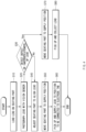
FIG. 1 is a perspective view of a general electrode assembly. - An
electrode assembly 10 is provided with a plurality ofelectrode tabs 20 extending from a plurality of electrodes, and each of the plurality ofelectrode tabs 20 is bonded to alead 30 by welding. Here, the plurality ofelectrode tabs 20 may include a plurality of positive electrode tabs extending from a plurality of positive electrodes, and a plurality of negative electrode tabs extending from a plurality of negative electrodes. Thelead 30 connected to the plurality of positive electrode tabs may be a positive electrode lead, and thelead 30 connected to the plurality of negative electrode tabs may be a negative electrode lead.FIG. 1 illustrates theelectrode assembly 10 in which the positive electrode tab and the negative electrode tab protrude in opposite directions. However, theelectrode assembly 10 is not limited thereto, and may also have a configuration in which the positive electrode tab and the negative electrode tab protrude in the same direction. - A process of bonding the
electrode tab 20 to thelead 30 includes supplying thelead 30 to a position at which thelead 30 is connected to theelectrode tabs 20, and welding theelectrode tab 20 to thelead 30 at the position. - In this regard, according to the related art, when the dimension or type of the
lead 30 changes, a worker manually adjusts settings, etc., of equipment so as to supply thelead 30 at a predetermined position in the supplying of thelead 30. However, there is a limit to such adjustment in that accuracy is reduced and it needs to be performed in a state in which the equipment is stopped. - An object of the present invention for solving the above problems is to provide a lead supply system, which automatically accurately aligns the lead so as to be connected to an electrode tab, and a method for controlling the lead supply system.
- A lead supply system according to an embodiment of the present invention may supply the lead so as to be connected to an electrode tab. The lead supply system may include: a seating part on which the lead is seated; a vision sensor that photographs the lead at an upper side of the seating part; an alignment mechanism that adjusts the seating part so as to align the lead on the basis of vision data photographed by the vision sensor; and a supply device that picks up the lead from the seating part so as to supply the lead to a position at which the lead is connected to the electrode tab.
- The lead supply system may further include a collecting box in which the lead is collected by the supply device when the lead is determined as a defect or inappropriateness on the basis of the vision data.
- The alignment mechanism may include a rotation motor, which is disposed below the seating part and rotates the seating part around a vertical axis, and an orthogonal robot which moves the rotation motor horizontally in first and second directions perpendicularly crossing each other.
- The alignment mechanism may move the seating part between a standby position disposed below the vision sensor and a supply position spaced apart from the standby position in the first direction. The supply device may pick up the lead when the seating part is disposed at the supply position.
- The supply device may include a gripper that holds the lead, and an orthogonal robot that moves the gripper in a second direction perpendicularly crossing the first direction and in a vertical direction.
- The lead supply system may further include a loading device that loads the lead on the seating part when the seating part is disposed at the standby position.
- The loading device may include an adsorption part that adsorbs the lead at an upper side, an elevation actuator that elevates the adsorption part, and a uniaxial actuator that moves the elevation actuator horizontally.
- The lead supply system may further include at least one of an overhead light unit, which emits light onto the lead from above the seating part, or a backlight unit provided in the seating part or disposed below the seating part.
- The lead supply system may further include a concentrative light unit that is provided toward the seating part and concentratively emits light onto a partial area on the lead.
- A method for controlling a lead supply system according to an embodiment of the present invention may include: a loading process of loading the lead on a seating part; a sensing process of photographing the lead on the seating part by a vision sensor; an alignment process of adjusting the seating part to align the lead on the basis of vision data photographed by the vision sensor; and a supply process of picking up the lead from the seating part to move the lead to a position at which the lead is connected to the electrode tab.
- The method may further include a collection process of picking up and collecting the lead when the lead is determined as a defect or inappropriateness on the basis of the vision data.
- The method may further include a moving process of moving the seating part in a first direction between the alignment process and the supply process.
- The supply process may include picking up the lead seated on the seating part by a gripper, and moving the gripper horizontally in a second direction perpendicularly crossing to the first direction.
- The sensing process may be performed in a state in which light is emitted toward the lead.
- According to the preferred embodiments of the present invention, the seating part may be adjusted to align the lead on the basis of the vision data photographed by the vision sensor. Accordingly, the lead may be supplied at the predetermined position at which the lead is connected to the electrode tab, and the quality of the electrode assembly may be improved.
- Even when the specification, etc., of the lead to be stocked changes, the alignment of the lead may be automatically performed without stopping the equipment. Accordingly, the productivity of the electrode assembly may increase.
- When the lead is determined as a defect or inappropriateness on the basis of the vision data photographed by the vision sensor, the lead may be collected but not supplied. Accordingly, the quality of the electrode assembly may be further improved.
- In addition, the effects may be included which could be easily predicted by those skilled in the art from the configurations according to the preferred embodiments of the present invention.
-
-
FIG. 1 is a perspective view of a general electrode assembly. -
FIG. 2 is a schematic diagram of a lead supply system according to an embodiment of the present invention. -
FIG. 3 is a control block diagram of the lead supply system according to an embodiment of the present invention. -
FIG. 4 is a flowchart of a method for controlling a lead supply system according to an embodiment of the present invention. -
FIGS. 5 to 9 are views for explaining operations of the lead supply system according to an embodiment of the present invention. -
FIG. 10 is a view for explaining a lead supply system according to another embodiment of the present invention. - Hereinafter, preferred embodiments of the present invention will be described in detail with reference to the accompanying drawings so as to enable those skilled in the art to which the present invention pertains to easily carry out the present invention. The present invention may, however, be embodied in different forms and should not be construed as limited by the embodiments set forth herein.
- The parts unrelated to the description, or the detailed descriptions of related well-known art that may unnecessarily obscure subject matters of the present invention, will be ruled out in order to clearly describe the present invention. Like reference numerals refer to like elements throughout the whole specification.
- Moreover, terms or words used in this specification and claims should not be restrictively interpreted as ordinary meanings or dictionary-based meanings, but should be interpreted as meanings and concepts conforming to the scope of the present invention on the basis of the principle that an inventor can properly define the concept of a term to describe his or her invention in the best ways.
-
FIG. 2 is a schematic diagram of a lead supply system according to an embodiment of the present invention. - Hereinafter, for convenience of explanation, a direction parallel to an X-axis in
FIG. 2 is called a first direction, and a direction parallel to a Y-axis is called a second direction. A Z-axis is parallel to a vertical direction and thus, the first direction and the second direction may be horizontal directions perpendicularly crossing each other. - A
lead supply system 100 according to an embodiment of the present invention may include aseating part 150 on which a lead 30 (seeFIG. 6 ) is seated, avision sensor 140 disposed above theseating part 150, analignment mechanism 151 that adjusts theseating part 150 so as to align thelead 30, and asupply device 170 that picks up thelead 30 from theseating part 150 so as to supply the lead to a preset position. - The
lead supply system 100 may further include aloading device 120 that loads thelead 30 on theseating part 150, and asupply buffer 110 that supplies thelead 30 to theloading device 120. - Hereinafter, for convenience of explanation, each of components of the
lead supply system 100 will be described according to the transfer order of thelead 30. - The
supply buffer 110 may sequentially supply thelead 30 manufactured in a previous process. Here, thelead 30 may be provided in a state in which an insulation film for post-sealing with a pouch type battery case (not shown) is attached to a portion of a circumference of thelead 30. - In more detail, the
supply buffer 110 may include a table 111 on which thelead 30 is seated, and auniaxial actuator 112 that moves the table 111. - The table 111 may be horizontally provided, and at least one
lead 30 may be seated on a top surface of the table 111. - The
uniaxial actuator 112 may move the table 111 horizontally in the second direction. In more detail, theuniaxial actuator 112 may include abase 112a coupled to a lower side of the table 111, and aguide 112b that guides movement of thebase 112a and extends in the second direction. Thus, the table 111 may move in the second direction together with thebase 112a. The detailed configuration and operation of theuniaxial actuator 112 are the well-known art and thus, the detailed description thereof will be omitted. - The table 111 may reciprocate, by the
uniaxial actuator 112, between an initial position at which thelead 30 is seated, and a supply position spaced apart from the initial position in the second direction. The supply position may be below theloading device 120 to be described later.FIG. 2 illustrates a state in which the table 111 is disposed at the supply position. - Thus, when the table 111 is disposed at the initial position, the
lead 30 may be seated on the table 111, and when the table 111, on which thelead 30 is seated, moves to the supply position by theuniaxial actuator 112, theloading device 120 may pick up thelead 30 seated on the table 111 so as to load thelead 30 on theseating part 150. - The
loading device 120 may be supported by asupport frame 130 so as to be disposed above thesupply buffer 110. - The
loading device 120 may include anadsorption part 121 that adsorbs thelead 30 at an upper side, anelevation actuator 122 that elevates theadsorption part 121, and auniaxial actuator 123 that moves theelevation actuator 122. - The
adsorption part 121 may vacuum-adsorb thelead 30 on the table 111 of thesupply buffer 110. In more detail, theadsorption part 121 may include a close-contact part 121a in close contact with a top surface of thelead 30, and asupport plate 121b on which the close-contact part 121a is suspended and supported. The close-contact part 121a may be communicated with a flexible pipe connected to a pump (not shown) that generates negative pressure. - The
elevation actuator 122 may elevate theadsorption part 121 in a vertical direction. Theelevation actuator 122 may be connected to theadsorption part 121, more particularly to thesupport plate 121b. - The
elevation actuator 122 may allow theadsorption part 121 to ascend so as to pick up the lead 30 from the table 111, or allow theadsorption part 121 to descend so as to load thelead 30 on theseating part 150. - The
uniaxial actuator 123 may be connected to theelevation actuator 122 and move theelevation actuator 122 horizontally in the first direction. In more detail, theuniaxial actuator 123 may include aconnection body 123a connected to theelevation actuator 122, and aguide 123b that guides movement of theconnection body 123a and extends in the first direction. The detailed configuration and operation of theuniaxial actuator 123 are the well-known art and thus, the detailed description thereof will be omitted. - Thus, the
adsorption part 121 may move horizontally in the first direction together with theelevation actuator 122. Theadsorption part 121 may pick up the lead 30 from the table 111 of thesupply buffer 110 and move in the first direction by theuniaxial actuator 123 so as to load the lead on theseating part 150. - The
support frame 130 may include aframe body 131 that supports theuniaxial actuator 123 of theloading device 120, and apillar 132 that supports thehorizontal frame body 131. Theframe body 131 may be elongated in a direction parallel to theuniaxial actuator 123 of theloading device 120, i.e., in the first direction. Thepillar 132 may be provided in plurality so as to stably support theframe body 131. - The
supply buffer 110 may be disposed to pass below theframe body 131. Theadsorption part 121 and theelevation actuator 122 of theloading device 120 may be disposed at one side in a width direction of theframe body 131. - The
lead 30 transferred by theloading device 120 may be seated on theseating part 150. Theseating part 150 may be horizontally disposed. - The
alignment mechanism 151 may adjust theseating part 150 so as to align thelead 30. Thealignment mechanism 151 may move theseating part 150 horizontally and rotate around a vertical axis. - In more detail, the
alignment mechanism 151 may include arotation motor 152 that rotates theseating part 150 around the vertical axis, and anorthogonal robot 153 that moves therotation motor 152 horizontally in the first direction and in the second direction. - The
rotation motor 152 may be disposed below theseating part 150 and connected to theseating part 150. Therotation motor 152 may precisely adjust an angle of theseating part 150. For example, therotation motor 152 may be a servo motor. - The
orthogonal robot 153 may include a mountingpart 153a, on which therotation motor 152 is mounted, afirst guide 153b, which guides movement of the mountingpart 153a and is elongated in one direction of the first direction and the second direction, and asecond guide 153c which guides movement of thefirst guide 153b and is elongated in the other direction of the first direction and the second direction. Thus, theseating part 150 may move in the first direction and in the second direction together with therotation motor 152. - The
seating part 150 may move, by thealignment mechanism 151, between a standby position (seeFIG. 6 ) disposed below thevision sensor 140, and a supply position (seeFIG. 7 ) spaced apart from the standby position in the first direction. That is, thealignment mechanism 151, more particularly theorthogonal robot 153, may reciprocate theseating part 150 between the standby position and the supply position.FIG. 2 illustrates a state in which theseating part 150 is disposed at the standby position. - In more detail, when the
seating part 150 is disposed at the standby position, thevision sensor 140 may photograph thelead 30 on theseating part 150, and thealignment mechanism 151 may adjust theseating part 150 so as to align thelead 30 on the basis of vision data photographed by thevision sensor 140. - When the alignment of the
lead 30 is completed, thealignment mechanism 151 may move theseating part 150 by a preset distance in the first direction, and theseating part 150 may reach the supply position. That is, the supply position is not a fixed position, but may vary slightly according to the alignment of thelead 30. When theseating part 150 moves to the supply position, thesupply device 170 may pick up thelead 30 on theseating part 150 so as to supply thelead 30 to a position at which thelead 30 is connected to theelectrode tab 20 of an electrode assembly 10 (seeFIG. 9 ). - The
vision sensor 140 may photograph thelead 30 at an upper side of theseating part 150. Thevision sensor 140 may be disposed above theseating part 150 that is the standby position. For example, thevision sensor 140 may include a camera. - The
vision sensor 140 may be supported by theframe body 131 of thesupport frame 130 descried above. In more detail, aconnection part 142 connected to thevision sensor 140 may be coupled to theframe body 131. - The
supply device 170 may be disposed to be spaced apart from theloading device 120 in the first direction. That is, thesupply device 170 may be disposed at a side opposite to theloading device 120 with theseating part 150 therebetween. - The
supply device 170 may include agripper 171 that holds thelead 30, and anorthogonal robot 172 that moves thegripper 171. - The
gripper 171 may hold thelead 30 seated on theseating part 150. In more detail, thegripper 171 may hold thelead 30 on theseating part 150 when theseating part 150 is disposed at the supply position (seeFIG. 7 ) described above. - For example, the
gripper 171 may include a pair of holding parts spaced apart from each other in an upward-downward direction, and an actuator that changes a distance between the pair of holding parts. In this case, thelead 30 may be held between the pair of holding parts. - The
orthogonal robot 172 may include afirst guide 172a that guides movement of thegripper 171 and is elongated in the second direction, and asecond guide 172b that guides movement of thefirst guide 172a and is elongated in the vertical direction. Theorthogonal robot 172 may further include athird guide 172c that guides movement of thesecond guide 172b and is elongated in the second direction. Thus, theorthogonal robot 172 may move thegripper 171 in the second direction and in the vertical direction. - The
orthogonal robot 172 may move thegripper 171 in the second direction so that thelead 30 on theseating part 150 is inserted between the pair of holding parts of thegripper 171. In this regard, a groove that prevents an interference to thegripper 171 may be defined in theseating part 150. - The
orthogonal robot 172 may allow thegripper 171 holding thelead 30 to ascend so as to pick up the lead 30 from theseating part 150. In a state in which thegripper 171 picks up thelead 30, theorthogonal robot 172 may allow thegripper 171 to move and descend in the second direction so as to supply thelead 30 to the position at which thelead 30 is connected to the electrode tab 20 (seeFIG. 9 ). - The
lead supply system 100 may further include acollecting box 160 in which thelead 30 defective or inappropriate is collected. - In more detail, if the
vision sensor 140 detects a defect or inappropriateness of thelead 30 when theseating part 150 is disposed at the standby position, thesupply device 170 may pick up and drop thelead 30 into thecollecting box 160 when theseating part 150 is disposed at the supply position. Thus, the defective orinappropriate lead 30 may be prevented from being supplied to the position at which thelead 30 is connected to the electrode tab 20 (seeFIG. 9 ). - The
collecting box 160 may have a top surface opened. Thecollecting box 160 may be disposed in a lateral direction of thesupply device 170. In more detail, thecollecting box 160 may be disposed below a point in a movement path of thegripper 171. Thus, when thegripper 171 releases the lead 30 from above thecollecting box 160, thelead 30 may be dropped into thecollecting box 160. - The
collecting box 160 may be supported by asupport frame 161 at a height similar to or a slightly lower than the height of theseating part 150. Thus, thelead 30 released from thegripper 171 may stably enter thecollecting box 160. -
FIG. 3 is a control block diagram of the lead supply system according to an embodiment of the present invention. - The
lead supply system 100 according to an embodiment of the present invention may further include acontroller 190. Thecontroller 190 may include at least one processor. - The
controller 190 may control an overall operation of thelead supply system 100. - The
controller 190 may control thesupply buffer 110, theloading device 120, and thesupply device 170. - The
controller 190 may communicate withvision sensor 140 to receive the vision data photographed by thevision sensor 140, and may control thealignment mechanism 151 to align thelead 30 on the basis of the vision data. In more detail, thecontroller 190 may analyze the vision data to extract an outline of thelead 130, and generate a control command for matching the outline with a predetermined position to deliver the control command to thealignment mechanism 151. - The
controller 190 may determine a defect and/or inappropriateness of thelead 30 on the basis of the vision data photographed by thevision sensor 140. - In one example, when one
lead 30 is below a predetermined specification or detected to be broken, the onelead 30 may be determined as a defect. - In another example, when the material of one
lead 30 does not match the polarity of the electrode tab 20 (seeFIG. 9 ), the onelead 30 may be determined as inappropriateness. In more detail, thecontroller 190 may analyze the vision data to determine the material of thelead 30 on the basis of the color property (e.g., chroma) of thelead 130, and may determine whether the material of the lead 30 matches polarity information of theelectrode tab 20. In this regard, theelectrode tab 20 of a negative electrode may match thelead 30 having a nickel or copper material, and theelectrode tab 20 of a positive electrode may match thelead 30 including an aluminum material. - When the
lead 30 is determined as a defect or inappropriateness, thecontroller 190 may control thesupply device 170 to collect thelead 30 in thecollecting box 160. In contrast, when thelead 30 is determined to be normal, thecontroller 190 may control thesupply device 170 to supply thelead 30 to the position at which thelead 30 is connected to theelectrode tab 20. -
FIG. 4 is a flowchart of a method for controlling a lead supply system according to an embodiment of the present invention.FIGS. 5 to 9 are views for explaining operations of the lead supply system according to an embodiment of the present invention. - A method for controlling a lead supply system according to an embodiment of the present invention (hereinafter referred to as a "control method") may include a loading process (S10), a sensing process (S20), an alignment process (S40), and a supply process (S60). The control method may further include a moving process (S50 or S70) and a collection process (S80).
-
FIG. 5 is a view for explaining the loading process (S10).FIG. 6 is a view for explaining the sensing process (S20) and the alignment process (S40).FIG. 7 is a view for explaining the moving process (S50 or S70).FIG. 8 is a view for explaining a process in which alead 30 is picked up in the supply process (S60).FIG. 9 is a view for explaining a process in which thelead 30 moves to a position, at which thelead 30 is connected to anelectrode tab 20, in the supply process (S60). - Hereinafter, the respective operations will be described in more detail.
- The loading process (S10) may be a process of loading the
lead 30 on theseating part 50. - Referring
FIGS. 2 and5 , theadsorption part 121 of theloading device 120 may ascend in a state in which theadsorption part 121 adsorbs thelead 30 on the table 111 of thesupply buffer 110, and move and descend in the first direction so as to load thelead 30 on theseating part 150. - Here, the
seating part 150 may be a standby position disposed below thevision sensor 140. That is, theadsorption part 121 may move between theseating part 150 and thevision sensor 140 so as to load thelead 30 on theseating part 150. - The sensing process (S20) may be a process of photographing the
lead 30 on theseating part 150 by thevision sensor 140. - Referring
FIGS. 2 and6 , theadsorption part 121 of theloading device 120 may return in the first direction so as to pick up thelead 30 on thesupply buffer 110. Thus, theadsorption part 121 is not be disposed between theseating part 150 and thevision sensor 140, and thevision sensor 140 may easily photograph thelead 30 on theseating part 150. - As described above, the
controller 190 may determine a defect and/or inappropriateness of thelead 30 on the basis of the vision data photographed by the vision sensor 140 (S30). In this regard, when thelead 30 is determined to be normal, the alignment process (S40) may be performed, and when thelead 30 is determined as a defect and/or inappropriateness, the collection process (S80) to be described later may be performed. - The alignment process (S40) may be a process of adjusting the
seating part 150 to align thelead 30 on the basis of the vision data photographed by thevision sensor 140. - The controller 190 (see
FIG. 3 ) may analyze the vision data photographed in the previous sensing process (S20) to generate a control command for aligning thelead 30 at a predetermined position and deliver the control command to thealignment mechanism 151. According to the control command, thealignment mechanism 151 may move theseating part 150 in the horizontal direction, and may rotate theseating part 150 at a predetermined angle around a vertical axis. In more detail, theseating part 150 may rotate at the predetermined angle by therotation motor 152 and move by theorthogonal robot 153 in the first direction and in the second direction. - The moving process (S50 or S70) may be a process of moving the
seating part 150 from the standby position to a supply position. In more detail, referringFIGS. 2 and7 , theseating part 150 may move in the first direction by thealignment mechanism 151, more particularly by theorthogonal robot 153. - The moving process (S50 or S70) may be performed between the alignment process (S40) and the supply process (S60) (S50), or performed before the collection process (S80) (S70). That is, the supply process (S60) and the collection process (S80) may be performed in a state in which the
seating part 150 is disposed at the supply position. - The supply process (S60) may be a process of picking up the lead 30 from the
seating part 150 to move thelead 30 to a position at which thelead 30 is connected to theelectrode tab 20. - Referring
FIGS. 2 ,8 , and9 , the supply process (S60) may include picking up thelead 30 seated on theseating part 150 by thegripper 171 of thesupply device 170, and moving thegripper 171 horizontally in the second direction. - The
gripper 171 of thesupply device 170 may ascend in a state in which thegripper 171 holds thelead 30 on theseating part 150, and move and descend in the second direction so as to transfer thelead 30 to the position at which thelead 30 is connected to theelectrode tab 20. - In this regard, the
electrode assembly 10 provided with theelectrode tab 20 may be sequentially supplied to a preset bonding position by atransfer system 200. In more detail, thetransfer system 200 may include a table 230, which moves horizontally (e.g., in the first direction) in a state in which theelectrode assembly 10 is disposed thereon, abonding unit 210, which bonds theelectrode tab 20 to thelead 30, and asupport part 220 which supports theelectrode tab 20 and the lead 30 from a lower side. - When the table 230 is disposed at the bonding position, the
electrode tab 20 may be disposed above thesupport part 220 and thegripper 171 may supply thelead 30 so as to be in contact with or adjacent to theelectrode tab 20. In such a state, thebonding unit 210 may descend so that theelectrode tab 20 and thelead 30 are pressed and bonded to each other between thebonding unit 210 and thesupport part 220. - For example, the
bonding unit 210 may include a mask jig and a laser unit, and theelectrode tab 20 and thelead 30 may be laser welded to each other. Configurations and operations for performing the laser welding are the well-known art and thus, the detailed description thereof will be omitted. - When the bonding of the
electrode tab 20 to thelead 30 is completed, thegripper 171 may release thelead 30 and return in the second direction. - After the alignment process (S40) is performed, the
seating part 150, on which thelead 30 is seated, moves by a preset distance in the first direction in the moving process (S50), and thegripper 171 holding thelead 30 moves by a preset distance in the second direction in the supply process (S60), so that thelead 30 after the alignment may be supplied to a predetermined position at which thelead 30 is connected to theelectrode tab 20. - Accordingly, the manufacturing quality of the
electrode assembly 10 may be improved. There is also an advantage that even when the specification, etc., of thelead 30 to be stocked in thesupply buffer 110 changes, the alignment may be automatically performed without stopping the equipment. - When the
lead 30 is determined as a defect and/or inappropriateness in the sensing process (S20), the collection process (S80) may be performed. That is, the collection process (S80) may be a process of picking up and collecting thelead 30 when thelead 30 is determined as a defect and/or inappropriateness on the basis of the vision data photographed by thevision sensor 40. - In more detail, the
gripper 171 may pick up thelead 30 on theseating part 150 that is the supply position, so as to collect thelead 30 in thecollecting box 160 instead of supplying thelead 30 to the position at which thelead 30 is connected to theelectrode tab 20. Accordingly, the defective orinappropriate lead 30 may be prevented from being provided in theelectrode assembly 10, and the quality of theelectrode assembly 10 may be further improved. - Alternatively, even when the
lead 30 is determined as a defect and/or inappropriateness, it may be possible to perform the alignment process (S40) unconditionally and then, perform the collection process (S80). -
FIG. 10 is a view for explaining a lead supply system according to another embodiment of the present invention. - The lead supply system according to this embodiment is the same as an embodiment described above except that a plurality of
light units - Referring to
FIGS. 2 and10 together, the lead supply system according to this embodiment may further include at least one of anoverhead light unit 181, which emits light onto a top surface of thelead 30 on theseating part 150, or abacklight unit 182 which emits the light onto a bottom surface of thelead 30 on theseating part 150. The lead supply system may further include a concentrativelight unit 183. - The overhead
light unit 181, thebacklight unit 182, and the concentrativelight unit 183 may emit light toward thelead 30 when thevision sensor 140 photographs thelead 30 on theseating part 150. That is, the sensing process (S20) (seeFIG. 4 ) described above may be performed in a state in which the light is emitted toward thelead 30. - The overhead
light unit 181 may be a coaxial light unit. The overheadlight unit 181 may be disposed above theseating part 150, particularly above theseating part 150 that is a standby position. That is, the overheadlight unit 181 may be provided in thevision sensor 140 or disposed to be adjacent to thevision sensor 140. The overheadlight unit 181 may be connected to theconnection part 142 together with thevision sensor 140 so as to be supported by theframe body 131. - The
backlight unit 182 may be disposed below theseating part 150, particularly below theseating part 150 that is the standby position. Alternatively, thebacklight unit 182 may be provided in theseating part 150. - Due to the overhead
light unit 181, shadows may be prevented from occurring on thelead 30 due to peripheral equipment, etc., and light reflection may be prevented from excessively occurring on thelead 30. Due to thebacklight unit 182, an outline of thelead 30 may become clearer. - Thus, due to the overhead
light unit 181 and thebacklight unit 182, an accurate outline of thelead 30 may be detected from the vision data photographed by thevision sensor 140, and thelead 30 may be more precisely aligned. - The concentrative
light unit 183 may be provided toward theseating part 150 and concentratively emit light onto a partial area on thelead 30. That is, the concentrativelight unit 183 may concentratively emit light onto a narrower area on the top surface of thelead 30 when compared to the overheadlight unit 181. The area onto which the light of the concentrativelight unit 183 is concentratively emitted may be disposed inward from the outline of thelead 30 so as not to interfere with the detection of the outline of thelead 30. - The concentrative
light unit 183 may be disposed to be adjacent to thevision sensor 140. The concentrativelight unit 183 may be connected to theconnection part 142 together with thevision sensor 140 so as to be supported by theframe body 131. The concentrativelight unit 183 may be disposed to be inclined. - Due to the concentrative
light unit 183, the color property (e.g., chroma) of thelead 30 and the material according to the color property may be accurately determined on the basis of the vision data photographed by thevision sensor 140. Thus, it may be more accurately determined whether the material of the lead 30 matches polarity information of theelectrode tab 20. - The description of the present invention is intended to be illustrative, and various changes and modifications can be made by those of ordinary skill in the art to which the present invention pertains, without departing from the spirit and scope of the present invention as defined by the appended claims.
- Therefore, the embodiments set forth herein are to describe the technical spirit of the present invention and not to limit. The scope of the technical spirit of the present invention is not limited by the embodiments.
- Moreover, the protective scope of the present invention should be determined by reasonable interpretation of the appended claims and all technical concepts coming within the equivalency range of the present application should be interpreted to be in the scope of the right of the present application.
-
10: Electrode assembly 20: Electrode tab 30: Lead 100: Lead supply system 110: Supply buffer 120: Loading device 130: Support frame 140: Vision sensor 150: Seating part 151: Alignment mechanism 152: rotation motor 153: Orthogonal robot 160: Collecting box 170: Supply device 171: Gripper 172: Orthogonal robot 181: Overhead light unit 182: Backlight unit 183: Concentrative light unit 190; Controller
Claims (14)
- A lead supply system configured to supply a lead so as to be connected to an electrode tab, the lead supply system comprising:a seating part on which the lead is seated;a vision sensor configured to photograph the lead at an upper side of the seating part;an alignment mechanism configured to adjust the seating part so as to align the lead on the basis of vision data photographed by the vision sensor; anda supply device configured to pick up the lead from the seating part so as to supply the lead to a position at which the lead is connected to the electrode tab.
- The lead supply system of claim 1, further comprising a collecting box in which the lead is collected by the supply device when the lead is determined as a defect or inappropriateness on the basis of the vision data.
- The lead supply system of claim 1, wherein the alignment mechanism comprises:a rotation motor disposed below the seating part and configured to rotate the seating part around a vertical axis; andan orthogonal robot configured to move the rotation motor horizontally in first and second directions perpendicularly crossing each other.
- The lead supply system of claim 1, wherein the alignment mechanism moves the seating part between a standby position disposed below the vision sensor and a supply position spaced apart from the standby position in a first direction, and
the supply device picks up the lead when the seating part is disposed at the supply position. - The lead supply system of claim 4, wherein the supply device comprises:a gripper configured to hold the lead; andan orthogonal robot configured to move the gripper in a second direction perpendicularly crossing the first direction and in a vertical direction.
- The lead supply system of claim 4, further comprising a loading device configured to load the lead on the seating part when the seating part is disposed at the standby position.
- The lead supply system of claim 6, wherein the loading device comprises:an adsorption part configured to adsorb the lead at an upper side;an elevation actuator configured to elevate the adsorption part; anda uniaxial actuator configured to move the elevation actuator horizontally.
- The lead supply system of claim 1, further comprising at least one of an overhead light unit configured to emit light onto the lead from above the seating part, or a backlight unit provided in the seating part or disposed below the seating part.
- The lead supply system of claim 8, further comprising a concentrative light unit provided toward the seating part and configured to concentratively emit light onto a partial area on the lead.
- A method for controlling a lead supply system that supplies a lead so as to be connected to an electrode tab, the method comprising:a loading process of loading the lead on a seating part;a sensing process of photographing the lead on the seating part by a vision sensor;an alignment process of adjusting the seating part to align the lead on the basis of vision data photographed by the vision sensor; anda supply process of picking up the lead from the seating part to move the lead to a position at which the lead is connected to the electrode tab.
- The method of claim 10, further comprising a collection process of picking up and collecting the lead when the lead is determined as a defect or inappropriateness on the basis of the vision data.
- The method of claim 10, further comprising a moving process of moving the seating part in a first direction between the alignment process and the supply process.
- The method of claim 12, wherein the supply process comprises:picking up the lead seated on the seating part by a gripper; andmoving the gripper horizontally in a second direction perpendicularly crossing to the first direction.
- The method of claim 10, wherein the sensing process is performed in a state in which light is emitted toward the lead.
Applications Claiming Priority (2)
| Application Number | Priority Date | Filing Date | Title |
|---|---|---|---|
| KR1020210117116A KR20230034027A (en) | 2021-09-02 | 2021-09-02 | Lead supply system and control method of the same |
| PCT/KR2022/012856 WO2023033472A1 (en) | 2021-09-02 | 2022-08-29 | Lead supply system and control method therefor |
Publications (2)
| Publication Number | Publication Date |
|---|---|
| EP4398409A1 true EP4398409A1 (en) | 2024-07-10 |
| EP4398409A4 EP4398409A4 (en) | 2025-07-09 |
Family
ID=85412836
Family Applications (1)
| Application Number | Title | Priority Date | Filing Date |
|---|---|---|---|
| EP22864974.5A Pending EP4398409A4 (en) | 2021-09-02 | 2022-08-29 | Lead feed system and control method therefor |
Country Status (6)
| Country | Link |
|---|---|
| US (1) | US20240342846A1 (en) |
| EP (1) | EP4398409A4 (en) |
| JP (1) | JP7693998B2 (en) |
| KR (1) | KR20230034027A (en) |
| CN (1) | CN117795763A (en) |
| WO (1) | WO2023033472A1 (en) |
Cited By (1)
| Publication number | Priority date | Publication date | Assignee | Title |
|---|---|---|---|---|
| EP4462530A4 (en) * | 2022-01-06 | 2025-04-30 | LG Energy Solution, Ltd. | ELECTRODE CONNECTION DEVICE |
Families Citing this family (1)
| Publication number | Priority date | Publication date | Assignee | Title |
|---|---|---|---|---|
| KR20240091447A (en) * | 2022-12-14 | 2024-06-21 | 주식회사 엘지에너지솔루션 | Apparatus for aligning electrode lead for manufacturing a battery |
Family Cites Families (9)
| Publication number | Priority date | Publication date | Assignee | Title |
|---|---|---|---|---|
| JP4995297B2 (en) * | 2010-03-26 | 2012-08-08 | 三菱重工業株式会社 | Battery and ultrasonic welding system used for manufacturing the battery |
| JP5953083B2 (en) | 2011-04-07 | 2016-07-13 | 日産自動車株式会社 | Laminating apparatus and laminating method |
| KR101516948B1 (en) * | 2013-10-18 | 2015-05-04 | (주)글로벌텍 | Welding apparatus |
| KR101542159B1 (en) * | 2013-11-12 | 2015-08-06 | 주식회사 폴 | Assembley device for lead tab and assembley method of lead tab using it |
| CN110178244B (en) * | 2016-12-29 | 2023-01-03 | 罗密欧系统公司 | System and method for cell structure, interconnection, sensing and balancing |
| WO2019017074A1 (en) | 2017-07-18 | 2019-01-24 | 株式会社村田製作所 | Electrode body manufacturing device |
| KR102081671B1 (en) * | 2018-08-28 | 2020-02-26 | 주식회사 폴 | Two Column Automatic Inspection System of Lead Tap for Senconday Battery |
| KR102808476B1 (en) * | 2019-07-08 | 2025-05-16 | 주식회사 엘지에너지솔루션 | Secondary battery and method for manufacturing the same |
| KR102738519B1 (en) | 2019-09-30 | 2024-12-04 | 현대자동차 주식회사 | Ultrasonic welding system of secondary battery and manufacturing method of secondary battery using the same |
-
2021
- 2021-09-02 KR KR1020210117116A patent/KR20230034027A/en active Pending
-
2022
- 2022-08-29 WO PCT/KR2022/012856 patent/WO2023033472A1/en not_active Ceased
- 2022-08-29 US US18/682,270 patent/US20240342846A1/en active Pending
- 2022-08-29 EP EP22864974.5A patent/EP4398409A4/en active Pending
- 2022-08-29 JP JP2024513822A patent/JP7693998B2/en active Active
- 2022-08-29 CN CN202280054456.9A patent/CN117795763A/en active Pending
Cited By (1)
| Publication number | Priority date | Publication date | Assignee | Title |
|---|---|---|---|---|
| EP4462530A4 (en) * | 2022-01-06 | 2025-04-30 | LG Energy Solution, Ltd. | ELECTRODE CONNECTION DEVICE |
Also Published As
| Publication number | Publication date |
|---|---|
| JP7693998B2 (en) | 2025-06-18 |
| KR20230034027A (en) | 2023-03-09 |
| WO2023033472A1 (en) | 2023-03-09 |
| EP4398409A4 (en) | 2025-07-09 |
| CN117795763A (en) | 2024-03-29 |
| US20240342846A1 (en) | 2024-10-17 |
| JP2024533136A (en) | 2024-09-12 |
Similar Documents
| Publication | Publication Date | Title |
|---|---|---|
| KR101956758B1 (en) | Machine for Manufacturing Cell Stack of Secondary Battery | |
| CN103460490B (en) | Lamination device and lamination method | |
| RU2555863C2 (en) | Electrode stacker and electrode stacking method | |
| KR101280069B1 (en) | System for Stacking Electrodes | |
| KR101992467B1 (en) | An electrode plate transfer apparatrus of a secondary battery manufacturing apparatus including an electrode plate inspection function | |
| EP4398409A1 (en) | Lead supply system and control method therefor | |
| US20140272528A1 (en) | Manufacturing techniques using binder coatings in three-dimensional stacked-cell batteries | |
| CN103460488A (en) | Electrode position detection device and electrode position detection method | |
| WO2019187042A1 (en) | Battery stack forming device and battery stack forming method | |
| KR20120137143A (en) | System for stacking electrodes | |
| JPWO2020110207A1 (en) | Positioning transfer device and positioning transfer method | |
| EP4357068A1 (en) | Apparatus for manufacturing secondary battery | |
| EP4340084B1 (en) | Electrode assembly folding device and electrode assembly folding method | |
| EP4425622A1 (en) | Automatic separator supply device | |
| KR102858164B1 (en) | Battery cell stacking system | |
| KR102890298B1 (en) | Electrode assembly folding apparatus and method using the same | |
| US20250026597A1 (en) | Automatic Separator Supply Apparatus | |
| EP4340085B1 (en) | Electrode assembly folding apparatus and electrode assembly folding method | |
| CN121368822A (en) | Battery cell stacking system | |
| KR20250078723A (en) | Secondary battery manufacturing apparatus and secondary battery manufacturing method using thereof | |
| CN117501490A (en) | Electrode assembly folding equipment and folding method using the electrode assembly folding equipment | |
| KR20260044094A (en) | Apparatus and method for aligning electrodes | |
| CN117529837A (en) | Electrode assembly folding device and folding method using the electrode assembly folding device | |
| KR20260024763A (en) | turn link type pick and place device | |
| KR20230059736A (en) | Electrode assembly folding apparatus and method using the same |
Legal Events
| Date | Code | Title | Description |
|---|---|---|---|
| STAA | Information on the status of an ep patent application or granted ep patent |
Free format text: STATUS: THE INTERNATIONAL PUBLICATION HAS BEEN MADE |
|
| PUAI | Public reference made under article 153(3) epc to a published international application that has entered the european phase |
Free format text: ORIGINAL CODE: 0009012 |
|
| STAA | Information on the status of an ep patent application or granted ep patent |
Free format text: STATUS: REQUEST FOR EXAMINATION WAS MADE |
|
| 17P | Request for examination filed |
Effective date: 20240122 |
|
| AK | Designated contracting states |
Kind code of ref document: A1 Designated state(s): AL AT BE BG CH CY CZ DE DK EE ES FI FR GB GR HR HU IE IS IT LI LT LU LV MC MK MT NL NO PL PT RO RS SE SI SK SM TR |
|
| DAV | Request for validation of the european patent (deleted) | ||
| DAX | Request for extension of the european patent (deleted) | ||
| A4 | Supplementary search report drawn up and despatched |
Effective date: 20250610 |
|
| RIC1 | Information provided on ipc code assigned before grant |
Ipc: H01M 10/04 20060101ALI20250604BHEP Ipc: H01M 50/531 20210101ALI20250604BHEP Ipc: H01M 50/564 20210101ALI20250604BHEP Ipc: H01M 50/557 20210101AFI20250604BHEP |
|
| STAA | Information on the status of an ep patent application or granted ep patent |
Free format text: STATUS: EXAMINATION IS IN PROGRESS |
|
| 17Q | First examination report despatched |
Effective date: 20260127 |