EP4398408A1 - Battery and bonding method - Google Patents
Battery and bonding method Download PDFInfo
- Publication number
- EP4398408A1 EP4398408A1 EP22864042.1A EP22864042A EP4398408A1 EP 4398408 A1 EP4398408 A1 EP 4398408A1 EP 22864042 A EP22864042 A EP 22864042A EP 4398408 A1 EP4398408 A1 EP 4398408A1
- Authority
- EP
- European Patent Office
- Prior art keywords
- electrode group
- electrode
- radial direction
- ridge line
- joined
- Prior art date
- Legal status (The legal status is an assumption and is not a legal conclusion. Google has not performed a legal analysis and makes no representation as to the accuracy of the status listed.)
- Pending
Links
Images

Classifications
-
- H—ELECTRICITY
- H01—ELECTRIC ELEMENTS
- H01M—PROCESSES OR MEANS, e.g. BATTERIES, FOR THE DIRECT CONVERSION OF CHEMICAL ENERGY INTO ELECTRICAL ENERGY
- H01M10/00—Secondary cells; Manufacture thereof
- H01M10/04—Construction or manufacture in general
- H01M10/0431—Cells with wound or folded electrodes
-
- H—ELECTRICITY
- H01—ELECTRIC ELEMENTS
- H01M—PROCESSES OR MEANS, e.g. BATTERIES, FOR THE DIRECT CONVERSION OF CHEMICAL ENERGY INTO ELECTRICAL ENERGY
- H01M10/00—Secondary cells; Manufacture thereof
- H01M10/05—Accumulators with non-aqueous electrolyte
- H01M10/058—Construction or manufacture
- H01M10/0587—Construction or manufacture of accumulators having only wound construction elements, i.e. wound positive electrodes, wound negative electrodes and wound separators
-
- H—ELECTRICITY
- H01—ELECTRIC ELEMENTS
- H01M—PROCESSES OR MEANS, e.g. BATTERIES, FOR THE DIRECT CONVERSION OF CHEMICAL ENERGY INTO ELECTRICAL ENERGY
- H01M50/00—Constructional details or processes of manufacture of the non-active parts of electrochemical cells other than fuel cells, e.g. hybrid cells
- H01M50/50—Current conducting connections for cells or batteries
- H01M50/531—Electrode connections inside a battery casing
- H01M50/533—Electrode connections inside a battery casing characterised by the shape of the leads or tabs
-
- H—ELECTRICITY
- H01—ELECTRIC ELEMENTS
- H01M—PROCESSES OR MEANS, e.g. BATTERIES, FOR THE DIRECT CONVERSION OF CHEMICAL ENERGY INTO ELECTRICAL ENERGY
- H01M50/00—Constructional details or processes of manufacture of the non-active parts of electrochemical cells other than fuel cells, e.g. hybrid cells
- H01M50/50—Current conducting connections for cells or batteries
- H01M50/531—Electrode connections inside a battery casing
- H01M50/538—Connection of several leads or tabs of wound or folded electrode stacks
-
- Y—GENERAL TAGGING OF NEW TECHNOLOGICAL DEVELOPMENTS; GENERAL TAGGING OF CROSS-SECTIONAL TECHNOLOGIES SPANNING OVER SEVERAL SECTIONS OF THE IPC; TECHNICAL SUBJECTS COVERED BY FORMER USPC CROSS-REFERENCE ART COLLECTIONS [XRACs] AND DIGESTS
- Y02—TECHNOLOGIES OR APPLICATIONS FOR MITIGATION OR ADAPTATION AGAINST CLIMATE CHANGE
- Y02E—REDUCTION OF GREENHOUSE GAS [GHG] EMISSIONS, RELATED TO ENERGY GENERATION, TRANSMISSION OR DISTRIBUTION
- Y02E60/00—Enabling technologies; Technologies with a potential or indirect contribution to GHG emissions mitigation
- Y02E60/10—Energy storage using batteries
-
- Y—GENERAL TAGGING OF NEW TECHNOLOGICAL DEVELOPMENTS; GENERAL TAGGING OF CROSS-SECTIONAL TECHNOLOGIES SPANNING OVER SEVERAL SECTIONS OF THE IPC; TECHNICAL SUBJECTS COVERED BY FORMER USPC CROSS-REFERENCE ART COLLECTIONS [XRACs] AND DIGESTS
- Y02—TECHNOLOGIES OR APPLICATIONS FOR MITIGATION OR ADAPTATION AGAINST CLIMATE CHANGE
- Y02P—CLIMATE CHANGE MITIGATION TECHNOLOGIES IN THE PRODUCTION OR PROCESSING OF GOODS
- Y02P70/00—Climate change mitigation technologies in the production process for final industrial or consumer products
- Y02P70/50—Manufacturing or production processes characterised by the final manufactured product
Definitions
- the electrode group 2 has a second joined region 48 in which the ends of a plurality of second electrode plates 8 (the second uncoated portion 14) arranged in the radial direction B are bent in the radial direction B. Each second uncoated portion 14 of this embodiment is bent toward the center of winding C.
- the electrode group 2 by way of one example has a plurality of second joined regions 48 at predetermined spacings in the circumferential direction of the electrode group 2.
- the electrode group 2 of this embodiment has four second joined regions 48 spaced at spacings of 90° in the circumferential direction. It should be noted that the electrode group 2 may include only one of the first joined regions 46 and the second joined regions 48. The first joined region 46 and the second joined region 48 will be described in detail later.
- the first joined region 46 extends to the outer edge of the electrode group 2 in the radial direction B. This makes it easier to ensure uniformity of the area joining the first electrode plate 6 and the first current collector plate 20 in each winding layer.
- the dimension of the first joined region 46 in the radial direction B is preferably 0.1D or more.
- the first electrode plate 6 of each winding layer is bent at a pair of ridge lines. This ensures uniformity of the width of the bent portion of each first electrode plate 6 (the dimension in the direction orthogonal to the imaginary line L). Uniform width of the bent portion also ensures uniformity of the depth of the bent portion of each first electrode plate 6. Thereby, the end of the first electrode plate 6 located outward can be bent in the same way as the end of the first electrode plate 6 located inward. This ensures uniformity of the area joining the first electrode plate 6 and the first current collector plate 20 in each winding layer.
- each ridge line such that the spacing M satisfies 0.1D ⁇ M ⁇ 0.25D. This makes it easy to ensure uniformity of the area joining the first electrode plate 6 and the first current collector plate 20 in each winding layer.
- the electrode group 2 included in the battery 1 has a joined area (at least one of the first joined region 46 and the second joined region 48) where the ends of the plurality of electrode plates (at least one of the first electrode plates 6 and the second electrode plates 8) arranged in the radial direction B are bent in the radial direction B, and where the ends of the plurality of electrode plates thus bent are joined to the current collector plate (at least one of the first current collector plate 20 and the second current collector plate 22).
- the joined region is sandwiched between two non-joined regions 50 arranged in the circumferential direction of the electrode group 2.
- the first boundary 52 and the second boundary 54 which are the boundaries between the joined region and the respective non-joined region 50, extend substantially parallel to the imaginary line L passing through the center of winding C and the joined region.
- Substantially parallel extension of the two boundaries produces a state in which the electrode plate of each winding layer is bent more uniformly. This ensures uniformity of the area joining the electrode plate and the current collector plate in each winding layer and increases the stability of joint between the electrode group 2 and the current collector plate. Accordingly, the quality of the battery 1 is improved.
- the embodiments may be defined by the following items.
- each of the first boundary portion (52) and the second boundary portion (54) extends such that an amount of displacement in a direction orthogonal to the imaginary line (L) is less than 0.075D.
Landscapes
- Chemical & Material Sciences (AREA)
- Chemical Kinetics & Catalysis (AREA)
- Electrochemistry (AREA)
- General Chemical & Material Sciences (AREA)
- Engineering & Computer Science (AREA)
- Manufacturing & Machinery (AREA)
- Connection Of Batteries Or Terminals (AREA)
- Secondary Cells (AREA)
Abstract
Description
- The present disclosure relates to a battery including an electrode group and a current collector plate and a method of joining an electrode group and a current collector plate.
- Conventionally, a battery in which a winding electrode group and an electrolytic solution are housed in a cylindrical outer can is known. In connection with such a battery,
PATENT LITERATURE 1 discloses a method of bending the end of the electrode group to form a flat welding surface and welding the welding surface and the current collector plate. - PATENT LITERATURE 1:
JP2015-106613 - We have found a technology for improving the quality of a battery in a method of joining a current collector plate to a welding surface formed by bending the end of the electrode group.
- The present disclosure addresses the issue described above, and a purpose thereof is to provide a technology for improving the quality of batteries.
- An embodiment of the present disclosure relates to a battery. The battery includes: a winding electrode group formed by stacking and winding a separator and an electrode plate; and a current collector plate. The electrode group has a joined region in which ends of a plurality of electrode plates arranged in a radial direction are bent in the radial direction and a plurality of bent ends are joined to the current collector plate. The joined region is sandwiched by two non-joined regions arranged in a circumferential direction of the electrode group, and a first boundary portion, which is a boundary between the joined region and one of the non-joined regions, and a second boundary portion, which is a boundary between the joined region and the other non-joined region, extend substantially parallel to a predetermined imaginary line passing through a center of winding of the electrode group and the joined region.
- Another embodiment of the present disclosure relates to a method of joining a winding electrode group formed by stacking and winding a separator and an electrode plate with a current collector plate. The method of joining includes: pressing a first processing tool against ends of a plurality of electrode plates arranged in a radial direction of the electrode group to form a first ridge line substantially parallel to an imaginary line passing through a center of winding of the electrode group and displaced in a circumferential direction of the electrode group with respect to the imaginary line; pressing, concurrently or after formation of the first ridge line, a second processing tool against the ends of the plurality of electrode plates arranged in the radial direction to form a second ridge line substantially parallel to the imaginary line and displaced in the circumferential direction with respect to the first ridge line; pressing a third processing tool against a section sandwiched between the first ridge line and the second ridge line to form a joined region by bending the ends of the plurality of electrode plates in the section in the radial direction; and joining the ends of the plurality of electrode plates bent in the joined region with the current collector plate.
- Optional combinations of the aforementioned constituting elements, and implementations of the disclosure in the form of methods, apparatuses, and systems may also be practiced as additional aspects of the present disclosure.
- According to the present disclosure, the quality of batteries can be improved.
-
-
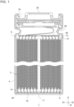
FIG. 1 is a cross-sectional view of a battery. -
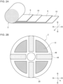
FIG. 2A is an exploded perspective view of an electrode group. -
FIG. 2B is a plan view of the electrode group to which the first current collector plate is joined. -
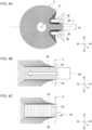
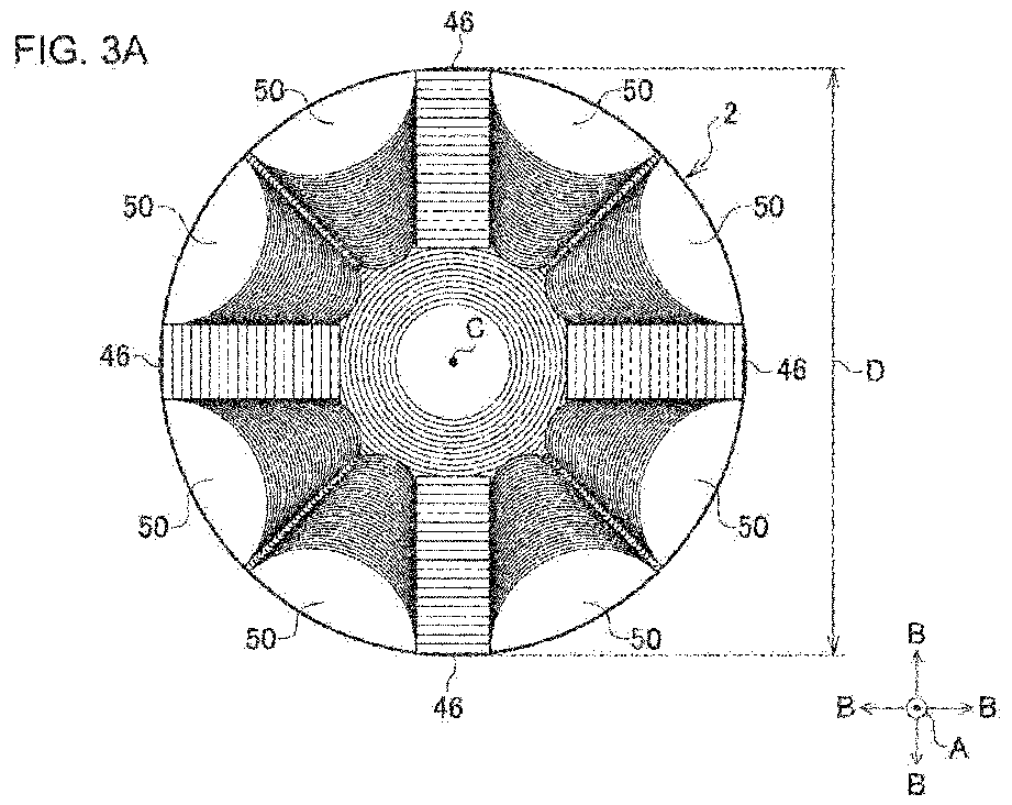
FIG. 3A is a plan view of the electrode group. -
FIG. 3B is an enlarged view of a set comprised of the first joined region and the non-joined regions. -
FIGS. 4A, 4B and 4C show the steps of forming the first joined region. -
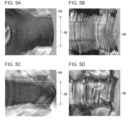
FIG. 5A shows the section photographed when the spacing M is 0.25D. -
FIG. 5B shows the first joined region photographed when the spacing M is 0.25D. -
FIG. 5C shows the section photographed when the spacing M is 0.1D. -
FIG. 5D shows the first joined region photographed when the spacing M is 0.1D. - Hereinafter, the present disclosure will be described based on preferred embodiments with reference to drawings. The embodiments do not limit the scope of the present disclosure but exemplify the disclosure. Not all of the features and the combinations thereof described in the embodiments are necessarily essential to the present disclosure. Identical or like constituting elements, members, processes shown in the drawings are represented by identical symbols and a duplicate description will be omitted as appropriate. The scales and shapes shown in the figures are defined for convenience's sake to make the explanation easy and shall not be interpreted limitatively unless otherwise specified. Terms like "first", "second", etc. used in the specification and claims do not indicate an order or importance by any means unless otherwise specified and are used to distinguish a certain feature from the others. Those of the members that are not material to the description of the embodiments are omitted in the drawings.
-
FIG. 1 is a cross-sectional view of abattery 1.FIG. 2A is an exploded perspective view of anelectrode group 2.FIG. 2B is a plan view of theelectrode group 2 to which the firstcurrent collector plate 20 is joined. InFIG. 2A , illustration of a firstuncoated portion 12 and a seconduncoated portion 14 is omitted. InFIG. 2B , illustration of a non-joinedregion 50 is omitted. - The
battery 1 is, for example, a rechargeable secondary battery such as a lithium ion battery, a nickel-metal hydride battery, and a nickel-cadmium battery. Thebattery 1 by way of one example has a structure in which theelectrode group 2 is stored in anouter can 4 along with a electrolytic solution (not shown). Theelectrode group 2 is cylindrical in shape by way of one example and, as shown inFIG. 2A , has a winding structure in which a belt-likefirst electrode plate 6 and a belt-likesecond electrode plate 8 are stacked, sandwiching a belt-like separator 10, and are wound in a spiral shape. In this embodiment, thefirst electrode plate 6 is the positive electrode plate and thesecond electrode plate 8 is the negative electrode plate, but the polarity of thefirst electrode plate 6 and thesecond electrode plate 8 may be reversed. Theseparator 10 is formed by a microporous film made of, by way of one example, a polypropylene resin or the like. - The
first electrode plate 6 and thesecond electrode plate 8 have a structure in which an electrode active material layer is stacked on a current collector. In the case of a general lithium ion secondary battery, the current collector is comprised of an aluminum foil or the like when it is a positive electrode and is comprised of a copper foil or the like when it is a negative electrode. The electrode active material layer can be formed by applying an electrode mixture material to the surface of the current collector by a known coating apparatus and drying and rolling the material. The electrode mixture material is obtained by kneading materials including an electrode active material, a binder, a conductive material, etc. in a dispersion medium and uniformly dispersing the materials. In the case of a general lithium ion secondary battery, the electrode active material is lithium cobalt oxide, lithium iron phosphate, or the like when it is a positive electrode and is graphite or the like when it is a negative electrode. - The
first electrode plate 6 has a firstuncoated portion 12 that is not coated with an electrode mixture material at the end on one side in the width direction A (a direction that intersects the longitudinal direction of the belt). The firstuncoated portion 12 is an exposed portion in the current collector of thefirst electrode plate 6 where the electrode active material layer is not stacked. Further, thesecond electrode plate 8 has a seconduncoated portion 14 not coated with an electrode mixture material at the end on the other side in the width direction A, that is, at the end opposite to the side where the firstuncoated portion 12 protrudes. The seconduncoated portion 14 is an exposed portion in the current collector of thesecond electrode plate 8 where the electrode active material layer is not stacked. - As described above, the
electrode group 2 has a structure in which thefirst electrode plate 6 and thesecond electrode plate 8 are wound. For this reason, a plurality of ends of thefirst electrode plate 6 and thesecond electrode plate 8 in the width direction A are arranged in the radial direction B of theelectrode group 2. Therefore, theelectrode group 2 includes a plurality of firstuncoated portions 12 arranged in the radial direction B and a plurality of seconduncoated portions 14 arranged in the radial direction B. - The
electrode group 2 has a first joinedregion 46 in which the ends of a plurality of first electrode plates 6 (the first uncoated portion 12) arranged in the radial direction B are bent in the radial direction B. Each firstuncoated portion 12 of this embodiment is bent toward the center of winding C of theelectrode group 2, i.e., bent inward in the radial direction B. The center of winding C is, for example, the geometric center of the outline of theelectrode group 2 seen in the width direction A, i.e., the geometric center of the outline of the shape of theelectrode group 2 projected in the width direction A. Theelectrode group 2 by way of one example has a plurality of first joinedregions 46 at predetermined spacings in the circumferential direction of theelectrode group 2. As shown inFIG. 2B , theelectrode group 2 of this embodiment has four first joinedregions 46 at spacings of 90° in the circumferential direction. - Further, the
electrode group 2 has a second joinedregion 48 in which the ends of a plurality of second electrode plates 8 (the second uncoated portion 14) arranged in the radial direction B are bent in the radial direction B. Each seconduncoated portion 14 of this embodiment is bent toward the center of winding C. Theelectrode group 2 by way of one example has a plurality of second joinedregions 48 at predetermined spacings in the circumferential direction of theelectrode group 2. Theelectrode group 2 of this embodiment has four second joinedregions 48 spaced at spacings of 90° in the circumferential direction. It should be noted that theelectrode group 2 may include only one of the first joinedregions 46 and the second joinedregions 48. The first joinedregion 46 and the second joinedregion 48 will be described in detail later. - A first
current collector plate 20 is provided on the side where the firstuncoated portion 12 in theelectrode group 2 protrudes. The firstcurrent collector plate 20 is made of, for example, aluminum or the like. The ends of the plurality offirst electrode plates 6 bent in the first joinedregion 46 are in surface contact with the firstcurrent collector plate 20. By bending the end of eachfirst electrode plate 6, the contact area between each firstuncoated portion 12 and the firstcurrent collector plate 20 increases. Then, laser welding or the like is performed at a position where the first joinedregion 46 and the firstcurrent collector plate 20 overlap, forming a joinedportion 44. Thereby, thefirst electrode plate 6 and the firstcurrent collector plate 20 of each winding layer are joined to each other. - A second
current collector plate 22 is provided on the side where the seconduncoated portion 14 in theelectrode group 2 protrudes. The secondcurrent collector plate 22 is made of, for example, copper, nickel, nickel-plated copper, nickel-plated iron, and the like. The ends of a plurality ofsecond electrode plates 8 bent in the second joinedregion 48 are in surface contact with the secondcurrent collector plate 22. By bending the end of eachsecond electrode plate 8, the contact area between each seconduncoated portion 14 and the secondcurrent collector plate 22 increases. Laser welding or the like is performed at a position where the second joinedregion 48 and the secondcurrent collector plate 22 overlap, forming a joined portion (not shown). Thereby, thesecond electrode plate 8 and the secondcurrent collector plate 22 of each winding layer are joined to each other. - The
electrode group 2 to which the firstcurrent collector plate 20 and the secondcurrent collector plate 22 are joined is stored in the bottomed cylindrical outer can 4 along with the electrolytic solution. Theouter can 4 is made of, for example, copper, nickel, iron, an alloy thereof, or the like. The secondcurrent collector plate 22 is joined to the inner bottom surface of theouter can 4 by welding or the like. The firstcurrent collector plate 20 is joined to a sealingplate 26 made of the same metal as theouter can 4 by welding or the like. The sealingplate 26 is fitted into the opening of theouter can 4 via an insulatinggasket 24. Thereby, theelectrode group 2 and the electrolytic solution are sealed in theouter can 4. - The shape of the joined region will now be described.
FIG. 3A is a plan view of theelectrode group 2.FIG. 3B is an enlarged view of a set comprised of the first joinedregion 46 and thenon-joined regions 50. Hereinafter, the shape of the joined region will be described with reference to the first joinedregion 46 as an example. The shape of the second joinedregion 48 is similar to that of the first joinedregion 46. - As described above, the
electrode group 2 of this embodiment includes four first joinedregions 46. The first joinedregions 46 are displaced from each other by 90° in the circumferential direction of theelectrode group 2. Each first joinedregion 46 is a substantially rectangular region extending in the radial direction B. Further, each first joinedregion 46 is sandwiched between twonon-joined regions 50 arranged in the circumferential direction of theelectrode group 2. Eachnon-joined region 50 is more recessed than the first joinedregion 46 in the width direction A and is a region that is not substantially joined to thefirst electrode plate 6. - Each first joined
region 46 has afirst boundary portion 52 and asecond boundary portion 54. Thefirst boundary portion 52 marks a boundary between the first joinedregion 46 and one of thenon-joined regions 50. Thesecond boundary 54 marks a boundary between the first joinedregion 46 and the othernon-joined region 50. Thefirst boundary portion 52 and thesecond boundary portion 54 are arranged in the circumferential direction of theelectrode group 2. - Each of the
first boundary portion 52 and thesecond boundary portion 54 extends substantially parallel to a predetermined imaginary line L passing through the center of winding C and the first joinedregion 46 of theelectrode group 2. Thus, thefirst boundary portion 52 and thesecond boundary portion 54 extend substantially parallel to each other. In this embodiment, "substantially parallel" means not only completely parallel to the counterpart (the imaginary line L, or thesecond boundary portion 54 with respect to the first boundary portion 52) but also covers a case where the distance from the counterpart at each position in the radial direction B is slightly displaced. For example, the term also covers a case in which the boundary portion extends by an amount of displacement of less than 0.075D, which is described later. The imaginary line L is a straight line located between thefirst boundary portion 52 and thesecond boundary portion 54. For example, the imaginary line L is a straight line passing through the geometric center of the outline of the first joinedregion 46 and the center of winding C as seen in the width direction A. Substantially parallel extension of the two boundary portions ensures uniformity of the range in thefirst electrode plate 6 in which the end thereof is bent in each winding layer. This ensures uniformity of the area joining thefirst electrode plate 6 and the firstcurrent collector plate 20 in each winding layer and increases the stability of joint between theelectrode group 2 and the firstcurrent collector plate 20. - Given that the diameter of the
electrode group 2 is denoted by D, each of thefirst boundary portion 52 and thesecond boundary portion 54 extends such that the amount of displacement in a direction orthogonal to the imaginary line L is preferably less than 0.075D. That is, the distance between the point closest to the imaginary line L and the farthest point in each boundary portion in a direction orthogonal to the imaginary line L, i.e., the parallelism of each boundary with respect to the imaginary line L is less than 0.075D. The diameter D is, for example, an average of the maximum outer diameter and the minimum outer diameter of theelectrode group 2 seen in the width direction A and is, for example, 15 mm-50 mm. It is desirable that each boundary portion is completely parallel to the imaginary line L. Even when the boundary portion meanders with respect to the imaginary line L, however, difficulty in ensuring uniformity of the area joining thefirst electrode plate 6 and the firstcurrent collector plate 20 in each winding layer is suppressed, by controlling the amount of displacement in the direction orthogonal to the imaginary line L in each boundary portion to be less than 0.075 times the diameter D. - Given that the spacing between the
first boundary portion 52 and thesecond boundary portion 54 at each position in the radial direction B is denoted by M and the diameter of theelectrode group 2 by D, the spacing M preferably satisfies 0.1D<M<0.25D. The spacing M is a distance between thefirst boundary portion 52 and thesecond boundary portion 54 in the direction orthogonal to the imaginary line L at each position in the radial direction B. By keeping the spacing M to be more than 0.1 times the diameter D of theelectrode group 2 and less than 0.25 times the diameter of D, it is easier to ensure uniformity of the area joining thefirst electrode plate 6 and the firstcurrent collector plate 20 in each winding layer. - Preferably, the first joined
region 46 extends to the outer edge of theelectrode group 2 in the radial direction B. This makes it easier to ensure uniformity of the area joining thefirst electrode plate 6 and the firstcurrent collector plate 20 in each winding layer. The dimension of the first joinedregion 46 in the radial direction B is preferably 0.1D or more. - The method of joining the
electrode group 2 and the current collector plate will now be described. Hereinafter, the method of joining theelectrode group 2 and the current collector plate will be described with reference to joint between the first joinedregion 46 and the firstcurrent collector plate 20 as an example. Joint between the second joinedregion 48 and the secondcurrent collector plate 22 is the same as in the case of the first joinedregion 46. - It should be noted that only one of the first joined
regions 46 and the second joinedregions 48 may be formed and joined to the current collector plate by the method according to this embodiment.FIGS. 4A-4C show the steps of forming the first joinedregion 46. - First, as shown in
FIG. 2A , thefirst electrode plate 6, thesecond electrode plate 8, and theseparators 10, which are belt-like, are prepared. Then, theseparator 10, thefirst electrode plate 6, theseparator 10, and thesecond electrode plate 8 are stacked in this order. The stacked product thus obtained is wound in a spiral shape to form the windingelectrode group 2. - Next, as shown in
FIG. 4A , afirst processing tool 56 is pressed, in a predetermined region of theelectrode group 2, against the ends of a plurality offirst electrode plates 6 arranged in the radial direction B, i.e., a plurality of firstuncoated portions 12 to bend the ends of the plurality offirst electrode plates 6 in the radial direction B. By way of one example, the end of eachfirst electrode plate 6 is bent inward in the radial direction B. Thefirst processing tool 56 has a surface parallel to the imaginary line L passing through the center of winding C and presses the ends of the plurality offirst electrode plates 6 with this surface. This forms afirst ridge line 58 substantially parallel to the imaginary line L and displaced in the circumferential direction of theelectrode group 2 with respect to the imaginary line L. - Further, a
second processing tool 60 is pressed against the ends of a plurality offirst electrode plates 6 arranged in the radial direction B to bend the ends of the plurality offirst electrode plates 6 in the radial direction B. Thesecond processing tool 60 has a surface parallel to the imaginary line L and presses the ends of a plurality offirst electrode plates 6 with this surface. Further, thesecond processing tool 60 presses a region arranged side by side with the region pressed by thefirst processing tool 56 in the circumferential direction of theelectrode group 2, with the imaginary line L in between. This forms asecond ridge line 62 that is substantially parallel to the imaginary line L and displaced in the circumferential direction with respect to thefirst ridge line 58, i.e., arranged side by side with thefirst ridge 58 in the circumferential direction, with the imaginary line L in between. The formation of thesecond ridge 62 may be concurrent with the formation of thefirst ridge 58 or after the formation of thefirst ridge 58. - When forming the
first ridge 58 and thesecond ridge 62, thefirst processing tool 56 and thesecond processing tool 60 pressed against the ends of thefirst electrode plates 6 are preferably displaced in the radial direction B and the direction approaching the imaginary line L. By way of one example, thefirst processing tool 56 and thesecond processing tool 60 of this embodiment move inward in the radial direction B toward the center of winding C, while also moving in the direction approaching the imaginary line L. Thus, by moving thefirst processing tool 56 and thesecond processing tool 60 at an angle to a region where the first joinedregion 46 is scheduled to be formed, while pressing thefirst processing tool 56 and thesecond processing tool 60 against theelectrode group 2, it is easier to form thefirst ridge line 58 and thesecond ridge line 62 parallel to the imaginary line L. - Further, it is more preferable to displace the
first processing tool 56 and thesecond processing tool 60 in a curved trajectory such that the amount of displacement in the radial direction B gradually decreases and the amount of displacement in the direction approaching the imaginary line L gradually increases. For example, thefirst processing tool 56 and thesecond processing tool 60 in the initial stage of displacement are displaced more significantly in the direction approaching the center of winding C than in the direction approaching the imaginary line L. Then, in the process of displacement, the amount of displacement in the direction approaching the imaginary line L gradually increases, and the amount of displacement approaching the center of winding C gradually decreases. As a result, thefirst processing tool 56 and thesecond processing tool 60 in the later stage of displacement are displaced more significantly in the direction approaching the imaginary line L than in the direction approaching the center of winding C. - That is, displacement of the
first processing tool 56 and thesecond processing tool 60 makes a transition from a mode in which the amount of displacement in the radial direction B is greater than the amount of displacement in the direction approaching the imaginary line L to a mode in which the amount of displacement in the direction approaching the imaginary line L is greater than the amount of displacement in the radial direction B. By displacing each processing tool in a curved trajectory, the process to bend the end of thefirst electrode plate 6 in the radial direction B is given priority in the initial stage of displacement of each processing tool. In the later stage of displacement, the end of eachfirst electrode plate 6 bent in the radial direction B is processed to be pressed toward the imaginary line L to form the ridge lines. This makes it easy to form thefirst ridge line 58 and asecond ridge 62 parallel to the imaginary line L. - Next, as shown in
FIG. 4B , athird processing tool 66 is pressed against asection 64 sandwiched between thefirst ridge line 58 and thesecond ridge line 62. Thethird processing tool 66 by way of one example has a surface facing theelectrode group 2 in the width direction A by a width substantially equal to the spacing M between thefirst ridge line 58 and thesecond ridge line 62. Thethird processing tool 66 moves in the radial direction B while pressing this surface against thesection 64. For example, thethird processing tool 66 moves inward in the radial direction B toward the center of winding C. The ends of the plurality offirst electrode plates 6 in thesection 64 are, when pressed by thethird processing tool 66, bent inward in the radial direction B, at thefirst ridge line 58 and thesecond ridge line 62. - This forms, as shown in
FIG. 4C , a substantially rectangular first joinedregion 46 extending in the radial direction B. The portion pressed and dented by thefirst processing tool 56 and the portion pressed and dented by thesecond processing tool 60 become thenon-joined regions 50. Further, thefirst ridge line 58 becomes thefirst boundary portion 52, and thesecond ridge line 62 becomes thesecond boundary portion 54. - In the winding
electrode group 2, thefirst electrode plate 6 located outward in the radial direction B is curved with a smaller curvature than thefirst electrode plate 6 located inward in the radial direction B. Therefore, the outerfirst electrode plate 6 is more likely to be bent in the radial direction B than the innerfirst electrode plate 6. When thesection 64 is pressed by thethird processing tool 66 without providing thefirst ridge line 58 and thesecond ridge line 62, therefore, the outerfirst electrode plate 6 tends to be bent at a position deeper than that of the innerfirst electrode plate 6, i.e., at a position farther from the end in the width direction A. The deeper the bent position, the larger the portion folded in the radial direction B. This results in the size of the portion where thefirst electrode plate 6 and the firstcurrent collector plate 20 are in contact varying from one winding layer to another. - When the
first ridge line 58 and thesecond ridge line 62 extending substantially parallel to each other are provided, on the other hand, thefirst electrode plate 6 of each winding layer is bent at a pair of ridge lines. This ensures uniformity of the width of the bent portion of each first electrode plate 6 (the dimension in the direction orthogonal to the imaginary line L). Uniform width of the bent portion also ensures uniformity of the depth of the bent portion of eachfirst electrode plate 6. Thereby, the end of thefirst electrode plate 6 located outward can be bent in the same way as the end of thefirst electrode plate 6 located inward. This ensures uniformity of the area joining thefirst electrode plate 6 and the firstcurrent collector plate 20 in each winding layer. - The
first ridge line 58 and thesecond ridge line 62 are preferably formed to be in contact with the outer edge of theelectrode group 2 in the radial direction B. That is, thefirst ridge line 58 and thesecond ridge line 62 extend to the outer edge of theelectrode group 2. Thereby, thefirst electrode plate 6 of the outermost layer, which tends to bent at the deepest position, is bent in the same way as the otherfirst electrode plates 6. This ensures uniformity of the area joining thefirst electrode plate 6 and the firstcurrent collector plate 20 in each winding layer. - The
first ridge line 58 and thesecond ridge line 62 are preferably formed to extend such that the amount of displacement in the direction orthogonal to the imaginary line L is less than 0.075D. This makes it easier to bend thefirst electrode plate 6 of each winding layer more uniformly. This ensures uniformity of the area joining thefirst electrode plate 6 and the firstcurrent collector plate 20 in each winding layer. - The
first ridge line 58 and thesecond ridge line 62 are preferably formed such that the spacing M between thefirst ridge line 58 and thesecond ridge line 62 at each position in the radial direction B satisfies 0.1D<M<0.25D.FIG. 5A shows thesection 64 photographed when the spacing M is 0.25D.FIG. 5B shows the first joinedregion 46 photographed when the spacing M is 0.25D.FIG. 5C shows thesection 64 photographed when the spacing M is 0.1D.FIG. 5D shows the first joinedregion 46 photographed when the spacing M is 0.1D. - We have found, through repeated examinations, that, as shown in
FIGS. 5A and 5B , thefirst electrode plate 6 outward in the radial direction B is more likely to be bent at a position deeper than that of thefirst electrode plate 6 inward when the interval M is 0.25 times or more than the diameter D of theelectrode group 2. We have also found that, as shown inFIGS. 5C and 5D , that, when the interval M is 0.1 times or less than the diameter D, the amount of flexure of eachfirst electrode plate 6 in the circumferential direction of theelectrode group 2 becomes excessive, causing it more likely that wrinkles are formed when eachfirst electrode plate 6 is bent by thethird processing tool 66. When wrinkles are formed in the first joinedregion 46, it becomes difficult to ensure uniformity of the area joining thefirst electrode plate 6 and the firstcurrent collector plate 20 in each winding layer. - Therefore, it is ensured that the depth of the bent position of each
first electrode plate 6 is more uniform and that formation of wrinkles is suppressed in the first joinedregion 46, by forming each ridge line such that the spacing M satisfies 0.1D<M<0.25D. This makes it easy to ensure uniformity of the area joining thefirst electrode plate 6 and the firstcurrent collector plate 20 in each winding layer. - The above-described process is also applied to other regions of the
electrode group 2 to form a further first joinedregion 46. Some or all of first joinedregions 46 may be formed concurrently. After all of the first joinedregions 46 are formed, the ends of a plurality offirst electrode plates 6 bent in the first joinedregion 46 and the firstcurrent collector plate 20 are joined as shown inFIG. 2B . - The same process is applied to the ends of the plurality of
second electrode plates 8 to form the second joinedregion 48. Then, the secondcurrent collector plate 22 is joined to the ends of the plurality ofsecond electrode plates 8 bent in the second joinedregion 48. Theelectrode group 2 to which the firstcurrent collector plate 20 and the secondcurrent collector plate 22 are joined is housed in theouter can 4 along with the electrolytic solution. Then, processes like joint of the secondcurrent collector plate 22 with theouter can 4, joint of the firstcurrent collector plate 20 with the sealingplate 26, fitting of the sealingplate 26 to the opening of theouter can 4, etc. are performed. Thereby, thebattery 1 is obtained. - As described above, the
electrode group 2 included in thebattery 1 according to this embodiment has a joined area (at least one of the first joinedregion 46 and the second joined region 48) where the ends of the plurality of electrode plates (at least one of thefirst electrode plates 6 and the second electrode plates 8) arranged in the radial direction B are bent in the radial direction B, and where the ends of the plurality of electrode plates thus bent are joined to the current collector plate (at least one of the firstcurrent collector plate 20 and the second current collector plate 22). The joined region is sandwiched between twonon-joined regions 50 arranged in the circumferential direction of theelectrode group 2. Thefirst boundary 52 and thesecond boundary 54, which are the boundaries between the joined region and the respectivenon-joined region 50, extend substantially parallel to the imaginary line L passing through the center of winding C and the joined region. - Substantially parallel extension of the two boundaries produces a state in which the electrode plate of each winding layer is bent more uniformly. This ensures uniformity of the area joining the electrode plate and the current collector plate in each winding layer and increases the stability of joint between the
electrode group 2 and the current collector plate. Accordingly, the quality of thebattery 1 is improved. - Further, the
first boundary portion 52 and thesecond boundary portion 54 of this embodiment extend such that the amount of displacement in the direction orthogonal to the imaginary line L is less than 0.075D. Further, the spacing M between thefirst boundary portion 52 and thesecond boundary portion 54 at each position in the radial direction B satisfies 0.1D<M<0.25D. Further, the joined region extends to the outer edge of theelectrode group 2 in the radial B. This makes it easier to ensure uniformity of the area joining the electrode plate and the current collector plate in each winding layer. - Further, the method of joining the electrode group 2 and the current collector plate (at least one of the first current collector plate 20 and the second current collector plate 22) according to this embodiment includes: pressing the first processing tool 56 against the ends of a plurality of first electrode plates arranged in the radial direction B (at least one of the first electrode plates 6 and the second electrode plates 8) to form the first ridge line 58 substantially parallel to the imaginary line L and displaced in the circumferential direction of the electrode group 2 with respect to the imaginary line L; pressing, concurrently or after the formation of the first ridge line 58, the second processing tool 60 against the ends of a plurality of electrode plates arranged in the radial direction B to form the second ridge line 62 substantially parallel to the imaginary line L and displaced in the circumferential direction with respect to the first ridge line 58; pressing the third processing tool 66 against the section 64 sandwiched between the first ridge line 58 and the second ridge line 62 to form a joined region (at least one of the first joined region 46 and the second joined region 48) by bending the ends of the plurality of electrode plates in the section 64 in the radial direction B; and joining the ends of the plurality of electrode plates bent in the joined region with the current collector plate.
- By providing the
first ridge line 58 and thesecond ridge line 62 substantially parallel to each other, and bending the electrode plates in each winding layer at the pair of ridge lines, the electrode plates are bent more uniformly. This ensures uniformity of the area joining the electrode plate and the current collector plate in each winding layer and increases the stability of joint between theelectrode group 2 and the current collector plate. Accordingly, the quality of thebattery 1 is improved. - Further, the joining method of this embodiment includes displacing the
first processing tool 56 and thesecond processing tool 60 in the radial direction B and the direction approaching the imaginary line L. Further, the joining method of this embodiment includes displacing thefirst processing tool 56 and thesecond processing tool 60 in a curved trajectory such that the amount of displacement in the radial direction B gradually decreases and the amount of displacement in the direction approaching the imaginary line L gradually increases. These make it easier to form thefirst ridge line 58 and thesecond ridge line 62 parallel to the imaginary line L. Accordingly, it is easier to ensure uniformity of the area joining the electrode plate and the current collector plate in each winding layer. - Further, the joining method of this embodiment includes forming the
first ridge line 58 and thesecond ridge line 62 to extend such that the amount of displacement in the direction orthogonal to the imaginary line L is less than 0.075D. Further, the method includes forming thefirst ridge line 58 and thesecond ridge line 62 such that the spacing M between thefirst ridge line 58 and thesecond ridge line 62 at each position in the radial direction B satisfies 0.1D<M<0.25D. Further, the method includes forming thefirst ridge line 58 and thesecond ridge line 62 to be in contact with the outer edge of theelectrode group 2 in the radial direction B. This makes it easier to ensure uniformity of the area joining the electrode plate and the current collector plate in each winding layer. - The embodiments of the present disclosure are described above in detail. The embodiments described above are merely specific examples of practicing the present disclosure. The details of the embodiment shall not be construed as limiting the technical scope of the present disclosure. A number of design modifications such as modification, addition, deletion, etc. of constituting elements may be made to the extent that they do not depart from the idea of the invention defined by the claims. New embodiments with design modifications will provide the combined advantages of the embodiment and the variation. Although the details subject to such design modification are emphasized in the embodiment described above by using phrases such as "of this embodiment" and "in this embodiment", details not referred to as such are also subject to design modification. Any combination of constituting elements included in the respective embodiments is also useful as an embodiment of the present disclosure. Hatching in the cross section in the drawings should not be construed as limiting the material of the hatched object.
- The embodiments may be defined by the following items.
- A battery (1) including:
- a winding electrode group (2) formed by stacking and winding a separator (10) and an electrode plate (6, 8); and
- a current collector plate (20, 22),
- wherein the electrode group (2) has a joined region (46, 48) in which ends of a plurality of electrode plates (6, 8) arranged in a radial direction (B) are bent in the radial direction (B) and a plurality of bent ends are joined to the current collector plate (20, 22),
- wherein the joined region (46, 48) is sandwiched by two non-joined regions (50) arranged in a circumferential direction of the electrode group (2), and a first boundary portion (52), which is a boundary between the joined region (46, 48) and one of the non-joined regions (50), and a second boundary portion (54), which is a boundary between the joined region (46, 48) and the other non-joined region (50), extend substantially parallel to a predetermined imaginary line (L) passing through a center of winding (C) of the electrode group (2) and the joined region (46, 48).
- The battery (1) according to
ITEM 1, wherein, given that a diameter of the electrode group (2) is denoted by D, each of the first boundary portion (52) and the second boundary portion (54) extends such that an amount of displacement in a direction orthogonal to the imaginary line (L) is less than 0.075D. - The battery (1) according to
ITEM 1 orITEM 2, wherein, given that a spacing between the first boundary portion (52) and the second boundary portion (54) at each position in the radial direction (B) is denoted by M and a diameter of the electrode group (2) is denoted by D, the spacing M satisfies 0.1D<M<0.25D. - The battery (1) according to any one of
ITEM 1 through ITEM 3, wherein the joined region (46, 48) extends to an outer edge of the electrode group (2) in the radial direction (B) . - A method of joining a winding electrode group (2) formed by stacking and winding a separator (10) and an electrode plate (6, 8) with a current collector plate (20, 22), including: pressing a first processing tool (56) against ends of a plurality of electrode plates (6, 8) arranged in a radial direction (B) of the electrode group (2) to form a first ridge line (58) substantially parallel to an imaginary line (L) passing through a center of winding (C) of the electrode group (2) and displaced in a circumferential direction of the electrode group (2) with respect to the imaginary line (L);
- pressing, concurrently or after formation of the first ridge line (58), a second processing tool (60) against the ends of the plurality of electrode plates (6, 8) arranged in the radial direction (B) to form a second ridge line (62) substantially parallel to the imaginary line (L) and displaced in the circumferential direction with respect to the first ridge line (58);
- pressing a third processing tool (66) against a section (64) sandwiched between the first ridge line (58) and the second ridge line (62) to form a joined region (46, 48) by bending the ends of the plurality of electrode plates (6, 8) in the section (64) in the radial direction (B); and
- joining the ends of the plurality of electrode plates (20, 22) bent in the joined region (46, 48) with the current collector plate (20, 22).
- The method of joining according to ITEM 5, including: displacing the first processing tool (56) and the second processing tool (60) in the radial direction (B) and a direction approaching the imaginary line (L).
- The method of joining according to
ITEM 6, including: displacing the first processing tool (56) and the second processing tool (60) in a curved trajectory such that an amount of displacement in the radial direction (B) gradually decreases and an amount of displacement in the direction approaching the imaginary line (L) gradually increases. - The method of joining according to any one of ITEM 5 through ITEM 7, including: forming, given that a diameter of the electrode group (2) is denoted by D, the first ridge line (58) and the second ridge line (62) to extend such that an amount of displacement in a direction orthogonal to the imaginary line (L) is less than 0.075D.
- The method of joining according to any one of ITEM 5 through
ITEM 8, including: forming, given that a spacing between the first ridge line (58) and the second ridge line (62) at each position in the radial direction (B) is denoted by M and a diameter of the electrode group (2) is denoted by D, the first ridge line (58) and the second ridge line (62) such that the spacing M satisfies 0.1D<M<0.25D. - The method of joining according to any one of claim 5 through 9, including: forming the first ridge line (58) and the second ridge line (62) to be in contact with an outer edge of the electrode group (2) in the radial direction (B).
- The present disclosure can be applied to batteries including an electrode group and a current collector plate and to a method of joining an electrode group and a current collector plate
- 1 battery, 2 electrode group, 6 first electrode plate, 8 second electrode plate, 10 separator, 20 first current collector plate, 22 second current collector plate, 46 first joined region, 48 second joined region, 50 non-joined region, 52 first boundary portion, 54 second boundary portion, 56 first processing tool, 60 second processing tool, 64 section, 66 third processing tool
Claims (10)
- A battery comprising:a winding electrode group formed by stacking and winding a separator and an electrode plate; anda current collector plate,wherein the electrode group has a joined region in which ends of a plurality of electrode plates arranged in a radial direction are bent in the radial direction and a plurality of bent ends are joined to the current collector plate,wherein the joined region is sandwiched by two non-joined regions arranged in a circumferential direction of the electrode group, and a first boundary portion, which is a boundary between the joined region and one of the non-joined regions, and a second boundary portion, which is a boundary between the joined region and the other non-joined region, extend substantially parallel to a predetermined imaginary line passing through a center of winding of the electrode group and the joined region.
- The battery according to claim 1,
wherein, given that a diameter of the electrode group is denoted by D, each of the first boundary portion and the second boundary portion extends such that an amount of displacement in a direction orthogonal to the imaginary line is less than 0.075D. - The battery according to claim 1 or 2,
wherein, given that a spacing between the first boundary portion and the second boundary portion at each position in the radial direction is denoted by M and a diameter of the electrode group is denoted by D, the spacing M satisfies 0.1D<M<0.25D. - The battery according to any one of claims 1 through 3,
wherein the joined region extends to an outer edge of the electrode group in the radial direction. - A method of joining a winding electrode group formed by stacking and winding a separator and an electrode plate with a current collector plate, comprising:pressing a first processing tool against ends of a plurality of electrode plates arranged in a radial direction of the electrode group to form a first ridge line substantially parallel to an imaginary line passing through a center of winding of the electrode group and displaced in a circumferential direction of the electrode group with respect to the imaginary line;pressing, concurrently or after formation of the first ridge line, a second processing tool against the ends of the plurality of electrode plates arranged in the radial direction to form a second ridge line substantially parallel to the imaginary line and displaced in the circumferential direction with respect to the first ridge line;pressing a third processing tool against a section sandwiched between the first ridge line and the second ridge line to form a joined region by bending the ends of the plurality of electrode plates in the section in the radial direction; andjoining the ends of the plurality of electrode plates bent in the joined region with the current collector plate.
- The method of joining according to claim 5, comprising:
displacing the first processing tool and the second processing tool in the radial direction and a direction approaching the imaginary line. - The method of joining according to claim 6, comprising:
displacing the first processing tool and the second processing tool in a curved trajectory such that an amount of displacement in the radial direction gradually decreases and an amount of displacement in the direction approaching the imaginary line gradually increases. - The method of joining according to any one of claims 5 through 7, comprising:
forming, given that a diameter of the electrode group is denoted by D, the first ridge line and the second ridge line to extend such that an amount of displacement in a direction orthogonal to the imaginary line is less than 0.075D. - The method of joining according to any one of claims 5 through 8, comprising:
forming, given that a spacing between the first ridge line and the second ridge line at each position in the radial direction is denoted by M and a diameter of the electrode group is denoted by D, the first ridge line and the second ridge line such that the spacing M satisfies 0.1D<M<0.25D. - The method of joining according to any one of claims 5 through 9, comprising:
forming the first ridge line and the second ridge line to be in contact with an outer edge of the electrode group in the radial direction.
Applications Claiming Priority (2)
| Application Number | Priority Date | Filing Date | Title |
|---|---|---|---|
| JP2021139952 | 2021-08-30 | ||
| PCT/JP2022/026388 WO2023032454A1 (en) | 2021-08-30 | 2022-06-30 | Battery and bonding method |
Publications (2)
| Publication Number | Publication Date |
|---|---|
| EP4398408A1 true EP4398408A1 (en) | 2024-07-10 |
| EP4398408A4 EP4398408A4 (en) | 2025-07-02 |
Family
ID=85412086
Family Applications (1)
| Application Number | Title | Priority Date | Filing Date |
|---|---|---|---|
| EP22864042.1A Pending EP4398408A4 (en) | 2021-08-30 | 2022-06-30 | BATTERY AND CONNECTION PROCEDURE |
Country Status (5)
| Country | Link |
|---|---|
| US (1) | US20250125400A1 (en) |
| EP (1) | EP4398408A4 (en) |
| JP (2) | JP7824967B2 (en) |
| CN (1) | CN117941160A (en) |
| WO (1) | WO2023032454A1 (en) |
Family Cites Families (9)
| Publication number | Priority date | Publication date | Assignee | Title |
|---|---|---|---|---|
| JP4023213B2 (en) * | 2002-05-20 | 2007-12-19 | 松下電器産業株式会社 | Lithium ion secondary battery |
| KR100560512B1 (en) * | 2003-11-29 | 2006-03-16 | 삼성에스디아이 주식회사 | Secondary battery |
| JP2007265846A (en) * | 2006-03-29 | 2007-10-11 | Sanyo Electric Co Ltd | Cylindrical battery and its manufacturing method |
| JP4446205B2 (en) * | 2008-04-14 | 2010-04-07 | トヨタ自動車株式会社 | Battery and manufacturing method thereof |
| KR101165503B1 (en) * | 2009-09-30 | 2012-07-13 | 삼성에스디아이 주식회사 | Rechargeable battery |
| JP5500970B2 (en) * | 2009-12-17 | 2014-05-21 | パナソニック株式会社 | Method for joining metal foil and metal plate |
| JP5428988B2 (en) * | 2010-03-25 | 2014-02-26 | トヨタ自動車株式会社 | Wound electrode body type battery, method for manufacturing the same, vehicle and device, and electrode winding device |
| WO2013001821A1 (en) * | 2011-06-28 | 2013-01-03 | 日本ケミコン株式会社 | Electricity storage device and method for manufacturing electricity storage device |
| WO2021020237A1 (en) * | 2019-07-30 | 2021-02-04 | 株式会社村田製作所 | Secondary battery, battery pack, electronic device, electric tool, electric airplane and electric vehicle |
-
2022
- 2022-06-30 CN CN202280058856.7A patent/CN117941160A/en active Pending
- 2022-06-30 EP EP22864042.1A patent/EP4398408A4/en active Pending
- 2022-06-30 WO PCT/JP2022/026388 patent/WO2023032454A1/en not_active Ceased
- 2022-06-30 JP JP2023545121A patent/JP7824967B2/en active Active
- 2022-06-30 US US18/687,267 patent/US20250125400A1/en active Pending
-
2026
- 2026-02-20 JP JP2026026078A patent/JP2026069695A/en active Pending
Also Published As
| Publication number | Publication date |
|---|---|
| JP2026069695A (en) | 2026-04-23 |
| US20250125400A1 (en) | 2025-04-17 |
| JP7824967B2 (en) | 2026-03-05 |
| CN117941160A (en) | 2024-04-26 |
| WO2023032454A1 (en) | 2023-03-09 |
| EP4398408A4 (en) | 2025-07-02 |
| JPWO2023032454A1 (en) | 2023-03-09 |
Similar Documents
| Publication | Publication Date | Title |
|---|---|---|
| JP2025087870A (en) | Cell with Tabless Structure Electrode | |
| KR102499324B1 (en) | Rolling Device for Secondary Battery | |
| EP2985805B1 (en) | Curved secondary battery and method of manufacturing the same | |
| US10062875B2 (en) | Method of manufacturing secondary battery including fixing tape and protection member, and secondary battery | |
| EP2555304A1 (en) | Battery cell | |
| WO2018061381A1 (en) | Non-aqueous electrolyte secondary battery | |
| US11050103B2 (en) | Pouch cell and method of forming same | |
| US20100304198A1 (en) | Electrode assembly for secondary battery and method of manufacturing the same | |
| CN110226244A (en) | Secondary battery | |
| US20160064720A1 (en) | Secondary-battery collector terminal and manufacturing method of secondary battery | |
| WO2013030879A1 (en) | Lithium-ion secondary battery and lithium-ion secondary battery manufacturing method | |
| US20120321942A1 (en) | Electrode assembly and secondary battery using the same | |
| CN108701856A (en) | Secondary battery | |
| EP4398408A1 (en) | Battery and bonding method | |
| US20240380010A1 (en) | Battery and joining method | |
| US11594751B2 (en) | Battery | |
| JP3763233B2 (en) | Flat battery and method of manufacturing the same | |
| EP4350822A1 (en) | Joining method | |
| CN222775412U (en) | Cells and Batteries | |
| EP4401178A1 (en) | Battery manufacturing method and battery | |
| EP4641815A1 (en) | Method for producing power storage device, and power storage device | |
| US20260024799A1 (en) | Electrode tab bending device and electrode tab bending method | |
| US20250174701A1 (en) | Winding roll structure for implementing edge bending of electrode assembly and winding method using the same | |
| US20250329793A1 (en) | Secondary battery and method of manufacturing same | |
| EP4560823B1 (en) | Apparatus for manufacturing secondary battery, method for manufacturing secondary battery using the same, and secondary battery manufactured using the same |
Legal Events
| Date | Code | Title | Description |
|---|---|---|---|
| STAA | Information on the status of an ep patent application or granted ep patent |
Free format text: STATUS: THE INTERNATIONAL PUBLICATION HAS BEEN MADE |
|
| PUAI | Public reference made under article 153(3) epc to a published international application that has entered the european phase |
Free format text: ORIGINAL CODE: 0009012 |
|
| STAA | Information on the status of an ep patent application or granted ep patent |
Free format text: STATUS: REQUEST FOR EXAMINATION WAS MADE |
|
| 17P | Request for examination filed |
Effective date: 20240307 |
|
| AK | Designated contracting states |
Kind code of ref document: A1 Designated state(s): AL AT BE BG CH CY CZ DE DK EE ES FI FR GB GR HR HU IE IS IT LI LT LU LV MC MK MT NL NO PL PT RO RS SE SI SK SM TR |
|
| DAV | Request for validation of the european patent (deleted) | ||
| DAX | Request for extension of the european patent (deleted) | ||
| A4 | Supplementary search report drawn up and despatched |
Effective date: 20250602 |
|
| RIC1 | Information provided on ipc code assigned before grant |
Ipc: H01M 50/533 20210101ALI20250526BHEP Ipc: H01M 10/0587 20100101ALI20250526BHEP Ipc: H01M 50/538 20210101AFI20250526BHEP |