EP4398380A1 - Tray and battery restraint device - Google Patents
Tray and battery restraint device Download PDFInfo
- Publication number
- EP4398380A1 EP4398380A1 EP22891170.7A EP22891170A EP4398380A1 EP 4398380 A1 EP4398380 A1 EP 4398380A1 EP 22891170 A EP22891170 A EP 22891170A EP 4398380 A1 EP4398380 A1 EP 4398380A1
- Authority
- EP
- European Patent Office
- Prior art keywords
- beams
- fixing rack
- boss
- external fixing
- examples
- Prior art date
- Legal status (The legal status is an assumption and is not a legal conclusion. Google has not performed a legal analysis and makes no representation as to the accuracy of the status listed.)
- Granted
Links
Images


Classifications
-
- B—PERFORMING OPERATIONS; TRANSPORTING
- B65—CONVEYING; PACKING; STORING; HANDLING THIN OR FILAMENTARY MATERIAL
- B65D—CONTAINERS FOR STORAGE OR TRANSPORT OF ARTICLES OR MATERIALS, e.g. BAGS, BARRELS, BOTTLES, BOXES, CANS, CARTONS, CRATES, DRUMS, JARS, TANKS, HOPPERS, FORWARDING CONTAINERS; ACCESSORIES, CLOSURES, OR FITTINGS THEREFOR; PACKAGING ELEMENTS; PACKAGES
- B65D19/00—Pallets or like platforms, with or without side walls, for supporting loads to be lifted or lowered
- B65D19/0002—Platforms, i.e. load supporting devices without provision for handling by a forklift
-
- H—ELECTRICITY
- H01—ELECTRIC ELEMENTS
- H01M—PROCESSES OR MEANS, e.g. BATTERIES, FOR THE DIRECT CONVERSION OF CHEMICAL ENERGY INTO ELECTRICAL ENERGY
- H01M50/00—Constructional details or processes of manufacture of the non-active parts of electrochemical cells other than fuel cells, e.g. hybrid cells
- H01M50/20—Mountings; Secondary casings or frames; Racks, modules or packs; Suspension devices; Shock absorbers; Transport or carrying devices; Holders
-
- H—ELECTRICITY
- H01—ELECTRIC ELEMENTS
- H01M—PROCESSES OR MEANS, e.g. BATTERIES, FOR THE DIRECT CONVERSION OF CHEMICAL ENERGY INTO ELECTRICAL ENERGY
- H01M50/00—Constructional details or processes of manufacture of the non-active parts of electrochemical cells other than fuel cells, e.g. hybrid cells
- H01M50/20—Mountings; Secondary casings or frames; Racks, modules or packs; Suspension devices; Shock absorbers; Transport or carrying devices; Holders
- H01M50/204—Racks, modules or packs for multiple batteries or multiple cells
-
- H—ELECTRICITY
- H01—ELECTRIC ELEMENTS
- H01M—PROCESSES OR MEANS, e.g. BATTERIES, FOR THE DIRECT CONVERSION OF CHEMICAL ENERGY INTO ELECTRICAL ENERGY
- H01M50/00—Constructional details or processes of manufacture of the non-active parts of electrochemical cells other than fuel cells, e.g. hybrid cells
- H01M50/20—Mountings; Secondary casings or frames; Racks, modules or packs; Suspension devices; Shock absorbers; Transport or carrying devices; Holders
- H01M50/218—Mountings; Secondary casings or frames; Racks, modules or packs; Suspension devices; Shock absorbers; Transport or carrying devices; Holders characterised by the material
- H01M50/22—Mountings; Secondary casings or frames; Racks, modules or packs; Suspension devices; Shock absorbers; Transport or carrying devices; Holders characterised by the material of the casings or racks
- H01M50/222—Inorganic material
-
- H—ELECTRICITY
- H01—ELECTRIC ELEMENTS
- H01M—PROCESSES OR MEANS, e.g. BATTERIES, FOR THE DIRECT CONVERSION OF CHEMICAL ENERGY INTO ELECTRICAL ENERGY
- H01M50/00—Constructional details or processes of manufacture of the non-active parts of electrochemical cells other than fuel cells, e.g. hybrid cells
- H01M50/20—Mountings; Secondary casings or frames; Racks, modules or packs; Suspension devices; Shock absorbers; Transport or carrying devices; Holders
- H01M50/218—Mountings; Secondary casings or frames; Racks, modules or packs; Suspension devices; Shock absorbers; Transport or carrying devices; Holders characterised by the material
- H01M50/22—Mountings; Secondary casings or frames; Racks, modules or packs; Suspension devices; Shock absorbers; Transport or carrying devices; Holders characterised by the material of the casings or racks
- H01M50/227—Organic material
-
- H—ELECTRICITY
- H01—ELECTRIC ELEMENTS
- H01M—PROCESSES OR MEANS, e.g. BATTERIES, FOR THE DIRECT CONVERSION OF CHEMICAL ENERGY INTO ELECTRICAL ENERGY
- H01M50/00—Constructional details or processes of manufacture of the non-active parts of electrochemical cells other than fuel cells, e.g. hybrid cells
- H01M50/20—Mountings; Secondary casings or frames; Racks, modules or packs; Suspension devices; Shock absorbers; Transport or carrying devices; Holders
- H01M50/244—Secondary casings; Racks; Suspension devices; Carrying devices; Holders characterised by their mounting method
-
- H—ELECTRICITY
- H01—ELECTRIC ELEMENTS
- H01M—PROCESSES OR MEANS, e.g. BATTERIES, FOR THE DIRECT CONVERSION OF CHEMICAL ENERGY INTO ELECTRICAL ENERGY
- H01M50/00—Constructional details or processes of manufacture of the non-active parts of electrochemical cells other than fuel cells, e.g. hybrid cells
- H01M50/20—Mountings; Secondary casings or frames; Racks, modules or packs; Suspension devices; Shock absorbers; Transport or carrying devices; Holders
- H01M50/262—Mountings; Secondary casings or frames; Racks, modules or packs; Suspension devices; Shock absorbers; Transport or carrying devices; Holders with fastening means, e.g. locks
- H01M50/264—Mountings; Secondary casings or frames; Racks, modules or packs; Suspension devices; Shock absorbers; Transport or carrying devices; Holders with fastening means, e.g. locks for cells or batteries, e.g. straps, tie rods or peripheral frames
-
- Y—GENERAL TAGGING OF NEW TECHNOLOGICAL DEVELOPMENTS; GENERAL TAGGING OF CROSS-SECTIONAL TECHNOLOGIES SPANNING OVER SEVERAL SECTIONS OF THE IPC; TECHNICAL SUBJECTS COVERED BY FORMER USPC CROSS-REFERENCE ART COLLECTIONS [XRACs] AND DIGESTS
- Y02—TECHNOLOGIES OR APPLICATIONS FOR MITIGATION OR ADAPTATION AGAINST CLIMATE CHANGE
- Y02E—REDUCTION OF GREENHOUSE GAS [GHG] EMISSIONS, RELATED TO ENERGY GENERATION, TRANSMISSION OR DISTRIBUTION
- Y02E60/00—Enabling technologies; Technologies with a potential or indirect contribution to GHG emissions mitigation
- Y02E60/10—Energy storage using batteries
Definitions
- This application relates to the field of battery processing equipment, and in particular, to a pallet and a battery restraint apparatus.
- a battery needs to be mounted on a restraint pallet that includes a pallet, and the restraint pallet is used to bear the weight of the battery. Because the restraint pallet needs to bear the weight of a battery cell, the restraint pallet is usually designed as a plate-shaped structure as a whole, and the overall weight of the pallet product is very heavy.
- the main objective of this application is to disclose a pallet, and aims to solve the problem that the existing pallet structure is very heavy.
- the pallet disclosed in this application is configured to bear a battery cell, and the pallet includes:
- a plurality of supporting beams are disposed to form load-bearing parts.
- the battery cells are borne by the load-bearing parts so that the battery cells are kept in preset positions.
- the supporting beams are arranged in the first direction, and at least two of the supporting beams are spaced apart, thereby reducing the weight of the load-bearing parts, reducing the overall weight of the pallet, and in turn, making the pallet more lightweight.
- the external fixing rack and/or the supporting beams are of a hollow tubular structure; and/or the external fixing rack and/or the supporting beams are made of a carbon fiber material.
- the overall weight of the pallet is reduced.
- the external fixing rack and/or supporting beams being made of a carbon fiber material, the structural strength of the external fixing rack and/or supporting beams is increased.
- the overall quality of the pallet is enhanced by virtue of the corrosion-resistant performance of carbon fiber material.
- a first boss is disposed on one of the supporting beam or the external fixing rack, and a first slot is recessed in the other thereof. The first boss is plugged into the first slot to connect the supporting beams to the external fixing rack.
- the supporting beams and the external fixing rack can be assembled quickly, thereby improving the mounting performance of the pallet.
- the first boss is also bonded to the first slot; and/or the first boss is disposed on the external fixing rack, and the first boss is bonded to the external fixing rack.
- the bonding between the first boss and the first slot avoids structural looseness and operation noise caused by wobbles of the supporting beams relative to the external fixing rack.
- the bonding between the first boss and the external fixing rack enables fast mounting and fixing of the first boss, reduces direct destructive processing of the external fixing rack and, in turn, increases the structural strength of the external fixing rack.
- the pallet further includes: a first reinforcing piece, where at least one of the supporting beams is connected to the external fixing rack by the first reinforcing piece.
- At least one supporting beam is connected to the external fixing rack by the first reinforcing piece, so as to improve the deformation resistance performance of the supporting beam, and in turn, prevent deformation or dislocation of the supporting beam that bears a load.
- the first reinforcing piece is plural in number.
- the plurality of first reinforcing pieces are spaced apart along a second direction, and the second direction intersects the first direction.
- the plurality of first reinforcing pieces are spaced apart along the second direction, and can support and fix the supporting beams along the second direction, thereby increasing the overall strength of the supporting beams and improving the deformation resistance performance.
- the first reinforcing piece is plugged and/or bonded to the external fixing rack.
- the plug-in connection and/or bonding between the reinforcing piece and the external fixing rack makes it convenient to fix the first reinforcing piece.
- the first reinforcing piece and the external fixing rack can be molded separately as required, and then assembled, thereby facilitating the molding and processing of individual structures.
- the supporting beams are plugged and/or bonded to the first reinforcing piece.
- the first reinforcing piece is fixed onto the supporting beam by plugging or bonding, so that the supporting beam and the first reinforcing piece can be molded separately. This facilitates the fast molding and processing of each component.
- the pallet further includes: a second reinforcing piece, where adjacent supporting beams are connected to each other by the second reinforcing piece.
- the second reinforcing piece is configured to connect adjacent supporting beams together, so that the adjacent supporting beams form an integral structure. This increases the overall strength of a plurality of supporting beams, enhances the overall deformation resistance performance of the plurality of supporting beams, and avoids deformation or displacement of the supporting beams.
- the second reinforcing piece is plugged and/or bonded to the supporting beams.
- the second reinforcing piece and the supporting beams can be separately molded and then mounted conveniently, thereby improving the mounting performance of a plurality of components.
- each of the supporting beams includes a lower surface, and the lower surface of the supporting beam is a plane; and/or at least two of the supporting beams are arranged in parallel.
- the supporting structure may be fit the lower surface of the supporting beam to prevent the pallet from shifting.
- two parallel supporting structures can coordinate with two parallel supporting beams on the pallet to improve stability of the pallet.
- a pin hole is made on the external fixing rack.
- the pin hole in these examples may be configured to fit with the external structure to mount the pallet onto another structure, and may fit with another structure to prevent the pallet from shifting and facilitate the fixing or stacking of pallets.
- the pallet further includes: a limiting assembly, mounted in the external fixing rack, where the pin hole is made on the limiting assembly, and a via-hole is made on the external fixing rack at a position corresponding to the pin hole.
- the limiting assembly in these examples is configured to form a pin hole.
- the limiting assembly includes:
- the fixing block in these examples is configured to be connected and fixed to the external fixing rack, and the pin sleeve is configured to form a pin hole. Because the pin sleeve is fixedly connected to the fixing block, a pin hole can be formed on the external fixing rack to facilitate the placement of the pallet.
- a first limiting hole and a second limiting hole communicating with the first limiting hole are made on the fixing block at a position corresponding to the via-hole.
- the second limiting hole is located between the first limiting hole and the via-hole.
- An inside diameter of the first limiting hole is greater than an inside diameter of the second limiting hole.
- a limiting boss is disposed protrusively on an outer wall of the pin sleeve.
- a major outside diameter of the limiting boss is greater than the inside diameter of the second limiting hole. The limiting boss is plugged into the first limiting hole, and the pin sleeve is plugged into the second limiting hole.
- the first limiting hole and the second limiting hole communicate with each other.
- the first limiting hole and the second limiting hole with different inside diameters are used to form a stepped internal structure on the fixing block.
- the limiting boss on the pin sleeve is limited to the interior of the stepped fixing block, thereby limiting the position of the pin sleeve and preventing the pin sleeve from moving along an axial direction of the first limiting hole.
- a convex lug is disposed on the fixing block.
- the convex lug is connected and fixed to the external fixing rack.
- the convex lug may serve as an intermediate connecting piece between the fixing block and the external fixing rack to mount and fix the fixing block onto the external fixing rack. It is therefore convenient to mount the fixing block.
- the convex lug is disposed at an end that is of the fixing block and that is away from the via-hole.
- the external fixing rack includes:
- Ends of at least two supporting beams are connected and fixed to the two first fixing beams respectively.
- the two first fixing beams are spaced apart, and the two second fixing beams are spaced apart.
- the two first fixing beams and the two second fixing beams are connected alternately end-to-end to form an approximately quadrilateral structure, so as to define a mounting space.
- the supporting beams are mounted in the mounting space.
- the ends of the supporting beams are connected to the two first fixing beams, so that the supporting beams are fixed onto the external fixing rack to implement fixing of the overall structure.
- a fifth boss is disposed protrusively on the second fixing beams, and a fifth slot is made on the first fixing beams.
- the fifth boss is plugged into in the fifth slot to connect the first fixing beams to the second fixing beams.
- the fifth boss is configured to fit with the fifth slot on the first fixing beams, so that the second fixing beams and the first fixing beams are connected and fixed to each other to form an integral framework structure of the external fixing rack.
- the fifth boss is also bonded to the fifth slot; and/or the fifth boss is plugged and/or bonded to the second fixing beams.
- the fifth boss and the second fixing beams can be molded separately, and then fixed to each other, thereby improving convenience of processing the fifth boss and the second fixing beams.
- the battery restraint apparatus is configured to restrain a battery cell.
- the battery restraint apparatus includes:
- the battery restraint apparatus can restrain the battery cell so that the battery cell can be kept in a preset position.
- the end plate is configured to limit the position of the battery cell to prevent the battery cell from moving toward the outside of the pallet, so that the battery cell can keep a steady state on the pallet.
- the external fixing rack includes an inner wall face oriented toward the mounting space and an outer wall face oriented away from the mounting space
- the pallet further includes: a connecting piece, connected to the external fixing rack and at least partly protruding from the outer wall face of the external fixing rack.
- the end plate is connected to the external fixing rack by the connecting piece.
- the connecting piece protrudes from the outer wall of the external fixing rack. Therefore, the part that is of the connecting piece and that protrudes from the external fixing rack can be connected and fixed to the end plate conveniently, so as to implement mounting and fixing of the end plate.
- Refe rence numeral Name Refer ence numeral Name 10 External fixing rack 11 First fixing beam 111 First boss 112 Fifth slot 113 Reserved hole 114 Threaded hole 12 Second fixing beam 121 Second boss 122 Fifth boss 123 Pin hole 124 Screw hole 20 Supporting beam 21 First slot 22 Third boss 23 Fourth boss 30 First reinforcing piece 31 Second slot 40 Second reinforcing piece 50 Limiting assembly 51 Fixing block 511 First limiting hole 512 Second limiting hole 513 Convex lug 52 Pin sleeve 521 Via-hole 522 Limiting boss 60 Connecting piece 61 Gasket 70 Restraint apparatus 71 End plate 72 Screw rod 73 Push plate 74 Fixing plate 80 Battery cell
- any technical terms such as “first” and “second” are used in an embodiment of this application, the terms such as “first” and “second” are merely intended for ease of description, but not intended to indicate or imply relative importance or implicitly specify the number of technical features mentioned. Therefore, the features preceded by “first” or “second” may explicitly or implicitly include at least one of such features.
- the technical solutions of different embodiments may be combined with each other to the extent practicable by a person of ordinary skilled in the art. When a combination of technical solutions is contradictory or impractical, the combination of technical solutions is considered to be nonexistent and fall outside the scope of protection claimed by this application.
- a battery cell includes an electrode assembly.
- the electrode assembly includes a positive electrode, a negative electrode, and a separator.
- active ions such as lithium ions
- the separator serves to prevent a short circuit between the positive electrode and the negative electrode and allow passage of the active ions.
- An active material layer of the positive electrode and an active material layer of the negative electrode are made of different materials.
- the most commonly used positive electrode materials include lithium cobalt oxide, lithium manganese oxide, lithium iron phosphate, and a ternary material (a nickel-cobalt-manganese polymer).
- Negative electrode materials used currently include natural graphite and artificial graphite primarily, and also include nitride, PAS, tin-based oxide, tin alloy, nanometric negative electrode material, and other intermetallic compounds.
- a pallet In a process of manufacturing a battery cell, in order to support the weight of the battery cell, a pallet needs to be disposed at the bottom of the battery cell.
- the pallet supports the battery cell so that the battery cell can move to a preset position as required.
- the pallet as a whole is of a sheet structure, so as to bear the total weight of the battery cell.
- this practice increases the weight of the pallet, and greatly increases energy consumption in the chemical formation process.
- an example of this application discloses a pallet configured to bear a battery cell.
- the pallet includes an external fixing rack 10 and a plurality of supporting beams 20.
- a mounting space is formed inside the external fixing rack 10.
- the plurality of supporting beams 20 are disposed in the mounting space.
- the plurality of supporting beams 20 are arranged along a first direction (that is, the 1a direction shown in FIG. 1 ).
- the plurality of supporting beams 20 are connected to the external fixing rack 10 separately. At least two of the supporting beams 20 are spaced apart.
- the plurality of supporting beams 20 are configured to bear the battery cell 80.
- the external fixing rack 10 forms an integral framework that includes a mounting space.
- the external fixing rack 10 may be a framework structure that is approximately rectangular.
- the mounting space is formed inside the external fixing rack 10 so that the external fixing rack 10 forms a hollow framework as a whole.
- the plurality of supporting beams 20 are all mounted in the mounting space. That is, the plurality of supporting beams 20 are all mounted inside the external fixing rack 10.
- the supporting beams 20 are configured to bear the battery cell 80 so that the battery cell 80 is kept in a preset position.
- the supporting beams 20 are connected to the external fixing rack 10 so that the plurality of supporting beams 20 can move synchronously with the external fixing rack 10.
- the plurality of supporting beams 20 are arranged along a first direction.
- the first direction may be a length direction or a width direction of the external fixing rack 10. In this example, the first direction is the width direction of the external fixing rack 10.
- the battery cell 80 In a chemical formation process of the battery cell 80, the battery cell 80 needs to be moved to a preset workspace together with the pallet.
- the two supporting beams 20 spaced apart may fit with the external supporting structure separately.
- the external supporting structure acts on the plurality of supporting beams 20 separately, so as to disperse the relative acting force exerted by the external supporting structure on the pallet.
- the parts of the external supporting structure, which are configured to bear the pallet can be staggered from each other, thereby preventing mutual interference between the plurality of bearing parts of the external supporting structure.
- the battery cell 80 In a chemical formation process, the battery cell 80 is in an environment with an electrolytic solution.
- the pallet includes a plurality of supporting beams 20 arranged along the first direction.
- the plurality of supporting beams 20 are spaced apart along the first direction. In this way, each supporting beam 20 is separated from an adjacent supporting beam 20, and each supporting beam 20 does not interfere with the adjacent supporting beam 20.
- the thickness of the supporting beam 20 is equal to the thickness of the external fixing rack 10. In this way, when the pallet is placed on a preset platform, both the supporting beam 20 and the external fixing rack 10 can be supported on the preset platform. In some examples, the thickness of the supporting beam 20 is less than the thickness of the external fixing rack 10. In this way, when the external fixing rack 10 is supported on the preset platform, the supporting beam 20 is suspended above the preset platform.
- the external fixing rack 10 is an integral framework structure, and the supporting beam 20 is fixed on the external fixing rack 10 that is in an integrity state.
- the external fixing rack 10 is a framework structure formed by combining a plurality of fixing beams.
- a plurality of supporting beams 20 are arranged parallel to each other.
- the plurality of supporting beams 20 include a first beam and a last beam along the first direction.
- the first beam and the last beam are the supporting beams 20 located at two ends of the first direction respectively.
- the first beam and the last beam are arranged parallel to each other.
- the first beam and the last beam are kept apart from the supporting beams 20 adjacent to the first beam and the last beam, so that the first beam and the last beam form independent supporting parts separately.
- an intermediate beam exists between the first beam and the last beam.
- the intermediate beam is disposed apart from the first beam and the last beam.
- three supporting beams 20 mentioned in any one of the above examples are mounted inside the external fixing rack 10.
- the three supporting beams 20 are spaced apart along the first direction.
- the three supporting beams 20 are arranged parallel to each other.
- Two supporting beams 20 located at two ends of the first direction are a first beam and a last beam respectively.
- the first beam and the last beam are connected to the external fixing rack 10 separately through the first reinforcing piece 30 mentioned in any one of the above examples.
- the supporting beam 20 in the middle is an intermediate beam.
- the intermediate beam is connected and fixed to the first beam and the last beam through the second reinforcing piece 40 mentioned in any one of the above examples.
- the external fixing rack 10 is of a hollow tubular structure.
- the external fixing rack 10 as a whole is of a hollow structure, thereby reducing the overall weight of the external fixing rack 10.
- the external fixing rack 10 may be integrally injection-molded, and may be formed by a combination of injection molding, winding, bending, or the like. Further, in some examples, the external fixing rack 10 is a whole.
- the external fixing rack 10 is defined by a tubular structure. In some examples, the external fixing rack 10 is a framework structure formed by combining a plurality of hollow tubular structures.
- a first boss 111 is disposed on one of the supporting beams 20 or the external fixing rack 10, and a first slot 21 is recessed in the other thereof.
- the first boss 111 is plugged into the first slot 21 to connect the supporting beams 20 to the external fixing rack 10.
- the first boss 111 fits with the first slot 21 to implement connection and fixing between the supporting beam 20 and the external fixing rack 10.
- the plug-in fixing facilitates connection between the supporting beam 20 and the external fixing rack 10, and enables quick assembly of the supporting beam 20 and the external fixing rack 10.
- the first boss 111 is disposed on the supporting beam 20.
- the first boss 111 and the supporting beam 20 may be formed in one piece, or the first boss 111 is fixedly mounted on the supporting beam 20 after the supporting beam 20 and the first boss 111 are formed separately.
- the first slot 21 is disposed on the external fixing rack 10.
- the first slot 21 may be a groove made on the external fixing rack 10. In this way, the first slot 21 can be formed at the same time as the external fixing rack 10.
- the accumulated electrolytic solution inside the supporting beam 20 or external fixing rack 10 is thereby prevented from causing problems such as corrosion inside the pallet.
- problems such as corrosion inside the pallet.
- the binder in these examples fills the clearance at the junctions between the external fixing rack 10 and the supporting beam 20, thereby preventing the accumulated impurities in the clearance between the two components from entering the chemical formation equipment of the battery cell 80, and in turn, preventing equipment pollution and improving product processing quality.
- the mounting position of the first boss 111 on the external fixing rack 10 can be adjusted before the binder is solidified, so as to implement adjustability of the position of the first boss 111. Due to the fit between the first boss and the supporting beam 20, when the position of the first boss 111 is adjusted, the relative position of the supporting beam 20 will also change, thereby facilitating the adjustment of the relative position of the supporting beam 20 and reducing the mounting error of the supporting beam 20.
- the first boss 111 may be plugged into the first slot 21 of the supporting beam 20 first, and then the first boss 111 is bonded to the external fixing rack 10. Further, in some examples, after the first boss 111 is plugged into the first slot 21, the clearance between the outer wall face of the first boss 111 and the inner wall face of the first slot 21 is filled with a binder, and the binder bonds and fixes the first boss 111 to the external fixing rack 10.
- the supporting beam 20 includes a first end and a second end arranged along the length direction.
- the first reinforcing piece 30 is located between the first end and the second end of the supporting beam 20 and is configured to connect and fix the external fixing rack 10 to the part that is of the supporting beam 20 and that is located between the first end and the second end, thereby preventing deformation of the part that is of the supporting beam 20 and that is away from the ends under pressure.
- the first reinforcing piece 30 may be disposed at a middle position in the length direction of the supporting beam 20, or the first reinforcing piece 30 may be disposed at a position close to the lengthwise middle of the supporting beam 20.
- the first direction may be a width direction of the external fixing rack 10
- the second direction may be a length direction of the external fixing rack 10
- the length direction of the supporting beam 20 may be parallel to the length direction of the external fixing rack 10, so that the first reinforcing pieces 30 are spaced apart along the length direction of the supporting beam 20.
- the second boss 121 is bonded to the external fixing rack 10, and then the second boss 121 on the external fixing rack 10 is plugged into the second slot 31 on the first reinforcing piece 30.
- the clearance between the inner wall face of the second slot 31 and the outer wall face of the second boss 121 is filled with the binder.
- the fourth slot is made on the second reinforcing piece 40, and the fourth boss 23 is disposed protrusively on the supporting beam 20, so that the second reinforcing piece 40 and the supporting beam 20 can fit each other by plugging.
- the fourth boss 23 and the supporting beam 20 may be formed in one piece, or the fourth boss 23 and the supporting beam 20 are formed separately, and then the fourth boss 23 and the supporting beam 20 are fixed to each other.
- At least two of the supporting beams 20 are arranged in parallel.
- the two parallel supporting beams 20 may be configured to fit with the external supporting structure, so as to facilitate arrangement of the external supporting structure and adaptation to other equipment.
- the plurality of supporting beams 20 are spaced apart along the first direction, and the plurality of supporting beams 20 are arranged parallel to each other.
- the lower surfaces of the plurality of supporting beams 20 are all planes, so that the lower surface of any supporting beam 20 can fit with the external supporting structure.
- the limiting assembly 50 includes a fixing block 51 and a pin sleeve 52.
- the fixing block 51 is fixedly mounted in the external fixing rack 10.
- the pin sleeve 52 is fixedly mounted on the fixing block 51.
- the pin hole 123 is made on the pin sleeve 52.
- the fixing block 51 in these examples serves as an intermediate connecting piece between the pin sleeve 52 and the external fixing rack 10.
- the pin sleeve 52 may be fixedly connected to the fixing block 51, or the pin sleeve 52 may be detachably connected to the fixing block 51.
- a first limiting hole 511 and a second limiting hole 512 that communicates with the first limiting hole 511 are made on the fixing block 51 at a position corresponding to the via-hole 521.
- the second limiting hole 512 is located between the first limiting hole 511 and the via-hole 521.
- the inside diameter of the first limiting hole 511 is greater than the inside diameter of the second limiting hole 512.
- a limiting boss 522 is disposed protrusively on the outer wall of the pin sleeve 52.
- a major outside diameter of the limiting boss 522 is greater than the inside diameter of the second limiting hole 512.
- the limiting boss 522 is plugged into the first limiting hole 511.
- the pin sleeve 52 is plugged into the second limiting hole 512.
- the first limiting hole 511 and the second limiting hole 512 may be coaxial holes, so as to facilitate molding and processing.
- the inside diameter of the second limiting hole 512 may be equal to the inside diameter of the via-hole 521.
- the first limiting hole 511 is located at an end that is of the second limiting hole 512 and that is away from the via-hole 521.
- the inside diameter of the first limiting hole 511 is greater than the inside diameter of the second limiting hole 512, so that the first limiting hole 511 and the second limiting hole 512 form an approximately step-shaped hole structure in the fixing block 51.
- the limiting boss 522 on the outer wall of the pin sleeve 52 is configured to fit with the first limiting hole 511.
- a convex lug 513 is disposed on the fixing block 51.
- the convex lug 513 is connected and fixed to the external fixing rack 10.
- the convex lug 513 is disposed protrusively on the fixing block 51.
- the convex lug 513 serves as an intermediate connecting piece between the fixing block 51 and the external fixing rack 10 to facilitate mounting of the fixing block 51.
- a threaded hole 114 is made on the convex lug 513, and a screw hole 124 is made on the external fixing rack 10.
- a screw is disposed on the external fixing rack 10. The screw runs through the screw hole 124 on the external fixing rack 10, and is threadedly connected to the threaded hole 114 on the convex lug 513.
- both the convex lug 513 and the fixing block 51 are bonded and fixed to the inner wall face of the external fixing rack 10.
- the convex lug 513 can increase the contact area between the limiting assembly 50 and the external fixing rack 10, thereby improving the stability of the fixing block 51.
- the convex lug 513 is disposed at an end that is of the fixing block 51 and that is away from the via-hole 521. Because the convex lug 513 can serve as an intermediate connecting piece between the external fixing rack 10 and the fixing block 51, when the convex lug 513 is disposed away from the via-hole 521, a connecting piece 60 such as a screw configured to connect the convex lug 513 can be disposed away from the via-hole 521 to reduce the operations such as hole drilling on the same surface of the external fixing rack 10. Further, the convex lug 513 in these examples are connected to the external fixing rack 10 by the screw in the preceding examples.
- the ends of at least two supporting beams 20 are connected and fixed to the two first fixing beams 11 respectively.
- the ends of the supporting beam 20 means the two ends of the supporting beam 20 along the second direction.
- the two first fixing beams 11 are disposed at the two ends of the supporting beam 20 along the second direction respectively
- the two second fixing beams 12 are disposed on the two sides of the supporting beam 20 along the first direction respectively.
- each of a plurality of supporting beams 20 is connected to the two first fixing beams 11 separately.
- the third direction in these examples means a clockwise or counterclockwise direction.
- a fifth boss 122 is disposed protrusively on the second fixing beams 12, and a fifth slot 112 is made on the first fixing beams 11.
- the fifth boss 122 is plugged into in the fifth slot 112 to connect the first fixing beams 11 to the second fixing beams 12.
- the fifth slot 112 is a groove that is recessed on the first fixing beam 11.
- the fifth boss 122 is connected to the second fixing beam 12. When the fifth boss 122 is plugged into the fifth slot 112, the movement of the first fixing beam 11 in the length direction of the second fixing beam 12 is obstructed by the fifth boss 122.
- the fifth boss 122 and the second fixing beam 12 are formed in one piece.
- the fifth boss 122 is mounted onto the second fixing beam 12.
- the first fixing beam 11 is of a hollow tubular structure
- the fifth slot 112 is a part of the hollow structure of the first fixing beam 11.
- the fifth slot 112 is made on the second fixing beam 12, and the fifth boss 122 is disposed on the first fixing beam 11.
- the fifth boss 122 is plugged to the second fixing beam 12. In this way, the fifth boss 122 and the second fixing beam 12 can be molded separately, and the molding steps are simplified. In these examples, the fifth boss 122 and the second fixing beam 12 may be made of the same material.
- the fifth boss 122 is bonded to the second fixing beam 12.
- the practice of bonding makes it convenient to mold the fifth boss 122 and the second fixing beam 12 separately and then assemble them together.
- the practice of bonding reduces the operations such as hole drilling on the second fixing beam 12, and increases the structural strength of the second fixing beam 12.
- the example of this application is merely an illustration of the pallet, and the battery cell 80 restraint apparatus 70 described in this example may further include other functional components such as a screw rod 72, a push plate 73, and a fixing plate 74 to achieve the effect of restraining the battery cell 80.
- the end plate 71 is connected to the first fixing beam 11 to restrict the battery cell 80 from at least two ends of the pallet.
- the end plate 71 in this example may be directly connected and fixed to the first fixing beam 11 by at least one of the following means: bolt, snap-fastening, pin, key-in connection, or welding; or, the first fixing beam 11 may be connected and fixed to the end plate 71 by an intermediate connecting piece.
- the restraint apparatus is applicable to various types of equipment such as chemical formation machines and capacity grading machines.
- the pallet is configured to bear a battery cell 80 when the battery cell 80 undergoes a process such as chemical formation.
- the pallet includes an external fixing rack 10 and a plurality of supporting beams 20 disposed inside the external fixing rack 10. At least two supporting beams 20 are spaced apart to reduce the overall weight of the pallet.
- the external fixing rack 10 is a rectangular structure defined by the two first fixing beams 11 and the two second fixing beams 12 that are connected to each other. Each of a plurality of supporting beams 20 is connected to the two first fixing beams 11 separately.
- both the supporting beams 20 and the external fixing rack 10 may be made of a carbon fiber material to enhance the corrosion-resistance performance of the pallet.
- the first boss 111 may fit into the first slot 21 to implement the assembling of the supporting beams 20.
- the clearance between the first boss 111 and a joint surface of the first slot is filled with a binder to prevent abrasion caused by the wobble of the supporting beams 20.
- a first reinforcing piece 30 is disposed between a supporting beam 20 and the external fixing rack 10.
- a second reinforcing piece 40 is disposed between adjacent supporting beams 20.
- the first reinforcing piece 30 and the second reinforcing piece 40 may also be made of a carbon fiber material.
- a pin hole 123 is made on the external fixing rack 10.
- the pin hole 123 fits with an external structure such as a pin to fix the pallet and limit the position of the pallet.
- a connecting piece 60 configured to connect the end plate 71 is disposed on the external fixing rack 10 to facilitate position limitation for the end plate 71 during restraint of the battery cell 80.
- different components may be connected to each other by a binder. Before the binder is solidified, the positions of corresponding components are adjustable to implement fine-tuning of the position of the corresponding structure.
Landscapes
- Chemical & Material Sciences (AREA)
- Chemical Kinetics & Catalysis (AREA)
- Electrochemistry (AREA)
- General Chemical & Material Sciences (AREA)
- Inorganic Chemistry (AREA)
- Engineering & Computer Science (AREA)
- Mechanical Engineering (AREA)
- Pallets (AREA)
- Battery Mounting, Suspending (AREA)
- Surgical Instruments (AREA)
Abstract
Description
- This application relates to the field of battery processing equipment, and in particular, to a pallet and a battery restraint apparatus.
- During a battery test, a battery needs to be mounted on a restraint pallet that includes a pallet, and the restraint pallet is used to bear the weight of the battery. Because the restraint pallet needs to bear the weight of a battery cell, the restraint pallet is usually designed as a plate-shaped structure as a whole, and the overall weight of the pallet product is very heavy.
- The main objective of this application is to disclose a pallet, and aims to solve the problem that the existing pallet structure is very heavy.
- To achieve the foregoing objective, the pallet disclosed in this application is configured to bear a battery cell, and the pallet includes:
- an external fixing rack, where a mounting space is formed inside the external fixing rack; and
- a plurality of supporting beams, disposed in the mounting space, where the plurality of supporting beams are arranged along a first direction, the plurality of supporting beams are connected to the external fixing rack separately, at least two of the supporting beams are spaced apart, and the plurality of supporting beams are configured to bear the battery cell.
- In this example, in the mounting space formed by the external fixing rack, a plurality of supporting beams are disposed to form load-bearing parts. The battery cells are borne by the load-bearing parts so that the battery cells are kept in preset positions. The supporting beams are arranged in the first direction, and at least two of the supporting beams are spaced apart, thereby reducing the weight of the load-bearing parts, reducing the overall weight of the pallet, and in turn, making the pallet more lightweight.
- In some examples, the external fixing rack and/or the supporting beams are of a hollow tubular structure; and/or the external fixing rack and/or the supporting beams are made of a carbon fiber material.
- With the external fixing rack and/or supporting beams being in the hollow tubular shape, the overall weight of the pallet is reduced. With the external fixing rack and/or supporting beams being made of a carbon fiber material, the structural strength of the external fixing rack and/or supporting beams is increased. In addition, the overall quality of the pallet is enhanced by virtue of the corrosion-resistant performance of carbon fiber material.
- In some examples, a first boss is disposed on one of the supporting beam or the external fixing rack, and a first slot is recessed in the other thereof. The first boss is plugged into the first slot to connect the supporting beams to the external fixing rack.
- By plugging and fitting the first boss and the first slot together, the supporting beams and the external fixing rack can be assembled quickly, thereby improving the mounting performance of the pallet.
- In some examples, the first boss is also bonded to the first slot; and/or the first boss is disposed on the external fixing rack, and the first boss is bonded to the external fixing rack.
- The bonding between the first boss and the first slot avoids structural looseness and operation noise caused by wobbles of the supporting beams relative to the external fixing rack.
- The bonding between the first boss and the external fixing rack enables fast mounting and fixing of the first boss, reduces direct destructive processing of the external fixing rack and, in turn, increases the structural strength of the external fixing rack.
- In some examples, the pallet further includes: a first reinforcing piece, where at least one of the supporting beams is connected to the external fixing rack by the first reinforcing piece.
- In these examples, at least one supporting beam is connected to the external fixing rack by the first reinforcing piece, so as to improve the deformation resistance performance of the supporting beam, and in turn, prevent deformation or dislocation of the supporting beam that bears a load.
- In some examples, the first reinforcing piece is plural in number. The plurality of first reinforcing pieces are spaced apart along a second direction, and the second direction intersects the first direction.
- In these examples, the plurality of first reinforcing pieces are spaced apart along the second direction, and can support and fix the supporting beams along the second direction, thereby increasing the overall strength of the supporting beams and improving the deformation resistance performance.
- In some examples, the first reinforcing piece is plugged and/or bonded to the external fixing rack.
- The plug-in connection and/or bonding between the reinforcing piece and the external fixing rack makes it convenient to fix the first reinforcing piece. In this way, the first reinforcing piece and the external fixing rack can be molded separately as required, and then assembled, thereby facilitating the molding and processing of individual structures.
- In some examples, the supporting beams are plugged and/or bonded to the first reinforcing piece.
- Because the first supporting beam is mounted on the external fixing rack, in these examples, the first reinforcing piece is fixed onto the supporting beam by plugging or bonding, so that the supporting beam and the first reinforcing piece can be molded separately. This facilitates the fast molding and processing of each component.
- In some examples, the pallet further includes: a second reinforcing piece, where adjacent supporting beams are connected to each other by the second reinforcing piece.
- In these examples, the second reinforcing piece is configured to connect adjacent supporting beams together, so that the adjacent supporting beams form an integral structure. This increases the overall strength of a plurality of supporting beams, enhances the overall deformation resistance performance of the plurality of supporting beams, and avoids deformation or displacement of the supporting beams.
- In some examples, the second reinforcing piece is plugged and/or bonded to the supporting beams.
- In these examples, by plugging and/or bonding the second reinforcing piece and the supporting beams together, the second reinforcing piece and the supporting beams can be separately molded and then mounted conveniently, thereby improving the mounting performance of a plurality of components.
- In some examples, each of the supporting beams includes a lower surface, and the lower surface of the supporting beam is a plane; and/or at least two of the supporting beams are arranged in parallel.
- By making the lower surface of the supporting beam be a plane, during relocation of the pallet, the supporting structure may be fit the lower surface of the supporting beam to prevent the pallet from shifting. By disposing at least two supporting beams in parallel, during relocation of the pallet, two parallel supporting structures can coordinate with two parallel supporting beams on the pallet to improve stability of the pallet.
- In some examples, a pin hole is made on the external fixing rack.
- The pin hole in these examples may be configured to fit with the external structure to mount the pallet onto another structure, and may fit with another structure to prevent the pallet from shifting and facilitate the fixing or stacking of pallets.
- In some examples, the pallet further includes: a limiting assembly, mounted in the external fixing rack, where the pin hole is made on the limiting assembly, and a via-hole is made on the external fixing rack at a position corresponding to the pin hole.
- The limiting assembly in these examples is configured to form a pin hole. By mounting the limiting assembly inside the external fixing rack, it is convenient to limit the limiting assembly and keep the limiting assembly in a preset position, thereby preventing the limiting assembly from occupying the external space of the external fixing rack, and facilitating integral stacking and placement of the external fixing rack.
- In some examples, the limiting assembly includes:
- a fixing block, fixedly mounted in the external fixing rack; and
- a pin sleeve, fixedly mounted on the fixing block, where the pin hole is made on the pin sleeve.
- The fixing block in these examples is configured to be connected and fixed to the external fixing rack, and the pin sleeve is configured to form a pin hole. Because the pin sleeve is fixedly connected to the fixing block, a pin hole can be formed on the external fixing rack to facilitate the placement of the pallet.
- In some examples, a first limiting hole and a second limiting hole communicating with the first limiting hole are made on the fixing block at a position corresponding to the via-hole. The second limiting hole is located between the first limiting hole and the via-hole. An inside diameter of the first limiting hole is greater than an inside diameter of the second limiting hole.
- A limiting boss is disposed protrusively on an outer wall of the pin sleeve. A major outside diameter of the limiting boss is greater than the inside diameter of the second limiting hole. The limiting boss is plugged into the first limiting hole, and the pin sleeve is plugged into the second limiting hole.
- In these examples, the first limiting hole and the second limiting hole communicate with each other. The first limiting hole and the second limiting hole with different inside diameters are used to form a stepped internal structure on the fixing block. The limiting boss on the pin sleeve is limited to the interior of the stepped fixing block, thereby limiting the position of the pin sleeve and preventing the pin sleeve from moving along an axial direction of the first limiting hole.
- In some examples, a convex lug is disposed on the fixing block. The convex lug is connected and fixed to the external fixing rack.
- In these examples, the convex lug may serve as an intermediate connecting piece between the fixing block and the external fixing rack to mount and fix the fixing block onto the external fixing rack. It is therefore convenient to mount the fixing block.
- In some examples, the convex lug is disposed at an end that is of the fixing block and that is away from the via-hole.
- By mounting the convex lug at the end that is of the fixing block and that is away from the via-hole, no structure such as a hole for connecting the convex lug needs to be disposed at the end that is of the external fixing rack and that is equipped with the via-hole, thereby reducing the hole making operations on the outer surface of the external fixing rack.
- In some examples, the external fixing rack includes:
- two first fixing beams; and
- two second fixing beams, where the two first fixing beams and the two second fixing beams are connected alternately end-to-end along a third direction, so that the two first fixing beams and the two second fixing beams close in to form the mounting space.
- Ends of at least two supporting beams are connected and fixed to the two first fixing beams respectively.
- In these examples, the two first fixing beams are spaced apart, and the two second fixing beams are spaced apart. The two first fixing beams and the two second fixing beams are connected alternately end-to-end to form an approximately quadrilateral structure, so as to define a mounting space. The supporting beams are mounted in the mounting space. The ends of the supporting beams are connected to the two first fixing beams, so that the supporting beams are fixed onto the external fixing rack to implement fixing of the overall structure.
- In some examples, a fifth boss is disposed protrusively on the second fixing beams, and a fifth slot is made on the first fixing beams. The fifth boss is plugged into in the fifth slot to connect the first fixing beams to the second fixing beams.
- In these examples, the fifth boss is configured to fit with the fifth slot on the first fixing beams, so that the second fixing beams and the first fixing beams are connected and fixed to each other to form an integral framework structure of the external fixing rack.
- In some examples, the fifth boss is also bonded to the fifth slot; and/or the fifth boss is plugged and/or bonded to the second fixing beams.
- By bonding and fixing the fifth boss to the fifth slot, relative vibration between the fifth boss and the first fixing beams can be prevented, thereby improving stability of the pallet. In these examples, by bonding and fixing the fifth boss to the second fixing beams, the fifth boss and the second fixing beams can be molded separately, and then fixed to each other, thereby improving convenience of processing the fifth boss and the second fixing beams.
- On the basis of the above pallet, this application further discloses an example of a battery restraint apparatus. The battery restraint apparatus is configured to restrain a battery cell. The battery restraint apparatus includes:
- the pallet described in any one of the examples given above; and
- an end plate, where the end plate is connected to the external fixing rack.
- In this example, the battery restraint apparatus can restrain the battery cell so that the battery cell can be kept in a preset position. The end plate is configured to limit the position of the battery cell to prevent the battery cell from moving toward the outside of the pallet, so that the battery cell can keep a steady state on the pallet.
- In some examples, the external fixing rack includes an inner wall face oriented toward the mounting space and an outer wall face oriented away from the mounting space, and the pallet further includes: a connecting piece, connected to the external fixing rack and at least partly protruding from the outer wall face of the external fixing rack.
- The end plate is connected to the external fixing rack by the connecting piece.
- In these examples, the connecting piece protrudes from the outer wall of the external fixing rack. Therefore, the part that is of the connecting piece and that protrudes from the external fixing rack can be connected and fixed to the end plate conveniently, so as to implement mounting and fixing of the end plate.
- To describe the technical solutions in some embodiments of this application or the prior art more clearly, the following outlines the drawings to be used in the description of some embodiments of this application or the prior art. Evidently, the drawings outlined below are merely a part of embodiments of this application. A person of ordinary skill in the art may derive other drawings from the illustrated structure without making any creative effort.
-
FIG. 1 is a schematic structural diagram of an example of a pallet according to this application; -
FIG. 2 is a close-up view of apart 1A shown inFIG. 1 ; -
FIG. 3 is a schematic structural diagram of an example of a first fixing beam according to this application; -
FIG. 4 is a schematic structural diagram of another example of a first fixing beam according to this application; -
FIG. 5 is a schematic structural diagram of an example of a second fixing beam according to this application; -
FIG. 6 is a schematic structural diagram of another example of a second fixing beam according to this application; -
FIG. 7 is a schematic structural diagram of an example of a supporting beam according to this application; -
FIG. 8 is a schematic structural diagram of another example of a supporting beam according to this application; -
FIG. 9 is a schematic structural diagram of another example of a pallet according to this application; -
FIG. 10 is a close-up view of a part 9A shown inFIG. 9 ; -
FIG. 11 is a schematic exploded view of an example of a limiting assembly according to this application; -
FIG. 12 is a schematic structural diagram of another example of a pallet according to this application; -
FIG. 13 is a close-up view of apart 12A shown inFIG. 12 ; -
FIG. 14 is a schematic structural diagram of an example of a battery restraint apparatus according to this application; and -
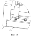
FIG. 15 is a close-up view of apart 14A shown inFIG. 14 . -
Refe rence numeral Name Refer ence numeral Name 10 External fixing rack 11 First fixing beam 111 First boss 112 Fifth slot 113 Reserved hole 114 Threaded hole 12 Second fixing beam 121 Second boss 122 Fifth boss 123 Pin hole 124 Screw hole 20 Supporting beam 21 First slot 22 Third boss 23 Fourth boss 30 First reinforcing piece 31 Second slot 40 Second reinforcing piece 50 Limiting assembly 51 Fixing block 511 First limiting hole 512 Second limiting hole 513 Convex lug 52 Pin sleeve 521 Via- hole 522 Limiting boss 60 Connecting piece 61 Gasket 70 Restraint apparatus 71 End plate 72 Screw rod 73 Push plate 74 Fixing plate 80 Battery cell - The objective fulfillment, functional characteristics, and advantages of this application will be described in more detail with reference to the drawings.
- The following clearly and thoroughly describes the technical solutions in some embodiments of this application with reference to the drawings appended hereto. Evidently, the described embodiments are merely a part of but not all of the embodiments of this application. All other embodiments derived by a person of ordinary skill in the art based on the embodiments of this application without making any creative efforts still fall within the scope of protection of this application.
- It is hereby noted that all directional terms (for example, up, down, left, right, front, back, and so on), if any, used in the embodiments of this application are merely used to explain a relative position relationship between components as well as the motion status and the like of the components in a specific posture (as shown in the drawings). When the specific posture changes, the directional terms change accordingly.
- In addition, if any technical terms such as "first" and "second" are used in an embodiment of this application, the terms such as "first" and "second" are merely intended for ease of description, but not intended to indicate or imply relative importance or implicitly specify the number of technical features mentioned. Therefore, the features preceded by "first" or "second" may explicitly or implicitly include at least one of such features. In addition, the technical solutions of different embodiments may be combined with each other to the extent practicable by a person of ordinary skilled in the art. When a combination of technical solutions is contradictory or impractical, the combination of technical solutions is considered to be nonexistent and fall outside the scope of protection claimed by this application.
- With the development of battery technology, batteries have penetrated every aspect of work and life. Lithium batteries are applied everywhere, ranging from a battery as small as a mobile phone battery to a battery as large as a battery module of a new energy vehicle. Generally, a battery cell includes an electrode assembly. The electrode assembly includes a positive electrode, a negative electrode, and a separator. During charge and discharge of a battery cell, active ions (such as lithium ions) are shuttled between the positive electrode and the negative electrode by intercalation and deintercalation. Disposed between the positive electrode and the negative electrode, the separator serves to prevent a short circuit between the positive electrode and the negative electrode and allow passage of the active ions. An active material layer of the positive electrode and an active material layer of the negative electrode are made of different materials. The most commonly used positive electrode materials include lithium cobalt oxide, lithium manganese oxide, lithium iron phosphate, and a ternary material (a nickel-cobalt-manganese polymer). Negative electrode materials used currently include natural graphite and artificial graphite primarily, and also include nitride, PAS, tin-based oxide, tin alloy, nanometric negative electrode material, and other intermetallic compounds. Some processes of manufacturing an electrode assembly involve slurry preparation, coating, cold pressing, winding, hot pressing, assembling, electrolyte injection, and chemical formation.
- In a process of manufacturing a battery cell, in order to support the weight of the battery cell, a pallet needs to be disposed at the bottom of the battery cell. The pallet supports the battery cell so that the battery cell can move to a preset position as required. In some circumstances, the pallet as a whole is of a sheet structure, so as to bear the total weight of the battery cell. However, this practice increases the weight of the pallet, and greatly increases energy consumption in the chemical formation process.
- Referring to
FIG. 1 and FIG. 2 , an example of this application discloses a pallet configured to bear a battery cell. The pallet includes anexternal fixing rack 10 and a plurality of supporting beams 20. A mounting space is formed inside theexternal fixing rack 10. The plurality of supportingbeams 20 are disposed in the mounting space. The plurality of supportingbeams 20 are arranged along a first direction (that is, the 1a direction shown inFIG. 1 ). The plurality of supportingbeams 20 are connected to theexternal fixing rack 10 separately. At least two of the supportingbeams 20 are spaced apart. The plurality of supportingbeams 20 are configured to bear thebattery cell 80. - The
external fixing rack 10 forms an integral framework that includes a mounting space. Theexternal fixing rack 10 may be a framework structure that is approximately rectangular. The mounting space is formed inside theexternal fixing rack 10 so that theexternal fixing rack 10 forms a hollow framework as a whole. - There are a plurality of supporting beams 20. The plurality of supporting
beams 20 are all mounted in the mounting space. That is, the plurality of supportingbeams 20 are all mounted inside theexternal fixing rack 10. The supporting beams 20 are configured to bear thebattery cell 80 so that thebattery cell 80 is kept in a preset position. The supporting beams 20 are connected to theexternal fixing rack 10 so that the plurality of supportingbeams 20 can move synchronously with theexternal fixing rack 10. The plurality of supportingbeams 20 are arranged along a first direction. The first direction may be a length direction or a width direction of theexternal fixing rack 10. In this example, the first direction is the width direction of theexternal fixing rack 10. - In this example, the plurality of supporting
beams 20 form supporting parts configured to bearbattery cells 80, and the supportingbeams 20 form a supporting surface configured to support thebattery cells 80. Among the plurality of supportingbeams 20, at least two supportingbeams 20 are spaced apart, which means that at least two supportingbeams 20 are separated from each other, and the corresponding two supportingbeams 20 are disconnected from each other. Because the supportingbeams 20 may be spaced apart, the supporting parts formed by the plurality of supportingbeams 20 do not unite into a whole, and clearances are formed between the supporting parts configured to support thebattery cells 80. In this way, the supporting surface formed by the supportingbeams 20 is prevented from forming a complete plane when the supportingbeams 20 bear thebattery cells 80. - The clearances between the formed supporting parts reduce the overall weight of the supporting parts, and in turn, reduce the weight of the pallet. The
external fixing rack 10 can form an external framework of the pallet. Therefore, thebattery cells 80 are mounted on the supportingbeams 20 inside theexternal fixing rack 10, and the supportingbeams 20 bear the weight of thebattery cells 80. Thebattery cells 80 are borne by the supportingbeams 20 that are spaced apart. No mutual traction force exists between the supportingbeams 20 that are spaced apart. When thebattery cells 80 are mounted on the pallet, the weight of thebattery cells 80 exerted on the spaced supportingbeams 20 is dispersed. Even if a single supportingbeam 20 is deformed, no mutual traction force exists between the supportingbeams 20, thereby preventing deformation of the supporting parts as a whole caused by the interaction between the supportingbeams 20, where the supporting parts are formed by the plurality of supporting beams 20. Because the plurality of supportingbeams 20 are connected to theexternal fixing rack 10 separately, it is convenient to connect and fix each supportingbeam 20 to theexternal fixing rack 10 separately during the mounting, thereby improving the mounting performance of the supporting beams 20. - In a chemical formation process of the
battery cell 80, thebattery cell 80 needs to be moved to a preset workspace together with the pallet. In this example, the two supportingbeams 20 spaced apart may fit with the external supporting structure separately. In this way, the external supporting structure acts on the plurality of supportingbeams 20 separately, so as to disperse the relative acting force exerted by the external supporting structure on the pallet. When the pallet interacts with the external supporting structure, due to the clearance between the supportingbeams 20, the parts of the external supporting structure, which are configured to bear the pallet, can be staggered from each other, thereby preventing mutual interference between the plurality of bearing parts of the external supporting structure. In a chemical formation process, thebattery cell 80 is in an environment with an electrolytic solution. When the electrolytic solution flows onto the pallet, the electrolytic solution can flow out along the clearances between adjacent supporting beams 20. The accumulated electrolytic solution on the pallet is therefore prevented from corroding the pallet. When the electrolytic solution flows out along the clearances between the adjacent supportingbeams 20, thebattery cells 80 mounted on the pallet are not prone to slide relative to the pallet. The stability of thebattery cells 80 is thereby improved. - In some examples, there are at least two groups of
battery cells 80, and each group includes at least onebattery cell 80. The number of groups ofbattery cells 80 is the same as the number of supporting beams 20. Each supportingbeam 20 bears a group ofbattery cells 80 correspondingly, so that the plurality of groups ofbattery cells 80 do not interfere with each other. The supporting beams 20 that bear different groups ofbattery cells 80 do not interfere with each other. Therefore, one supportingbeam 20 that is deformed does not affect other supportingbeams 20, thereby preventing the overall deformation of the pallet. - In some examples, the pallet includes a plurality of supporting
beams 20 arranged along the first direction. The plurality of supportingbeams 20 are spaced apart along the first direction. In this way, each supportingbeam 20 is separated from an adjacent supportingbeam 20, and each supportingbeam 20 does not interfere with the adjacent supportingbeam 20. - In some examples, the
external fixing rack 10 is a rectangular framework structure. The mounting space is approximately rectangular. A plurality of supportingbeams 20 are mounted in the mounting space. Further, in some examples, at least two supportingbeams 20 are arranged parallel to the length direction of theexternal fixing rack 10. The two parallel supportingbeams 20 are kept apart from each other, and apart from the adjacent supportingbeam 20, by a clearance, so that the two parallel supportingbeams 20 can be configured to bear thebattery cells 80 separately. - In some examples, the thickness of the supporting
beam 20 is equal to the thickness of theexternal fixing rack 10. In this way, when the pallet is placed on a preset platform, both the supportingbeam 20 and theexternal fixing rack 10 can be supported on the preset platform. In some examples, the thickness of the supportingbeam 20 is less than the thickness of theexternal fixing rack 10. In this way, when theexternal fixing rack 10 is supported on the preset platform, the supportingbeam 20 is suspended above the preset platform. - Referring to
FIG. 2 to FIG. 6 , in some examples, theexternal fixing rack 10 is an integral framework structure, and the supportingbeam 20 is fixed on theexternal fixing rack 10 that is in an integrity state. In some examples, theexternal fixing rack 10 is a framework structure formed by combining a plurality of fixing beams. - Referring to
FIG. 1 ,FIG. 7 ,FIG. 8 , andFIG. 9 , further, in some examples, a plurality of supportingbeams 20 are arranged parallel to each other. In some examples, the plurality of supportingbeams 20 include a first beam and a last beam along the first direction. The first beam and the last beam are the supportingbeams 20 located at two ends of the first direction respectively. The first beam and the last beam are arranged parallel to each other. Moreover, the first beam and the last beam are kept apart from the supportingbeams 20 adjacent to the first beam and the last beam, so that the first beam and the last beam form independent supporting parts separately. In some examples, an intermediate beam exists between the first beam and the last beam. The intermediate beam is disposed apart from the first beam and the last beam. In some examples, three supportingbeams 20 mentioned in any one of the above examples are mounted inside theexternal fixing rack 10. The three supportingbeams 20 are spaced apart along the first direction. The three supportingbeams 20 are arranged parallel to each other. Two supportingbeams 20 located at two ends of the first direction are a first beam and a last beam respectively. The first beam and the last beam are connected to theexternal fixing rack 10 separately through the first reinforcingpiece 30 mentioned in any one of the above examples. The supportingbeam 20 in the middle is an intermediate beam. The intermediate beam is connected and fixed to the first beam and the last beam through the second reinforcingpiece 40 mentioned in any one of the above examples. - Referring to
FIG. 3, FIG. 4, FIG. 5 , andFIG. 6 , in some examples, theexternal fixing rack 10 is of a hollow tubular structure. In this way, theexternal fixing rack 10 as a whole is of a hollow structure, thereby reducing the overall weight of theexternal fixing rack 10. Theexternal fixing rack 10 may be integrally injection-molded, and may be formed by a combination of injection molding, winding, bending, or the like. Further, in some examples, theexternal fixing rack 10 is a whole. Theexternal fixing rack 10 is defined by a tubular structure. In some examples, theexternal fixing rack 10 is a framework structure formed by combining a plurality of hollow tubular structures. - In some embodiments, the
external fixing rack 10 is made of a carbon fiber material. The carbon fiber material is a composite material formed by soaking and fusing carbon fiber bundles constructed from a resin matrix and short fibers. During processing, a molten prepreg containing the resin matrix and the carbon fiber bundles is added into a preset mold. The product in the mold forms a preset shape. Theexternal fixing rack 10 is formed from a carbon fiber material to effectively enhance the overall corrosion resistance performance and structural strength of theexternal fixing rack 10. In this way, thebattery cell 80 is not prone to corrosion and abrasion in an electrolytic solution environment during chemical formation. - In some examples, the supporting
beam 20 is of a hollow tubular structure, thereby reducing the overall weight of the supportingbeam 20, and in turn, implementing the lightweight design of the pallet. In these examples, the supportingbeam 20 may be a hollow tubular shape that is integrally injection-molded, or may be formed by a combination of injection molding, winding, bending, and the like. In these examples, the supportingbeam 20 may be made by the same process as theexternal fixing rack 10. - In some examples, the supporting
beam 20 is made of the carbon fiber material mentioned in the above example. Further, the supportingbeam 20 may be made of the same material as theexternal fixing rack 10. - Referring to
FIG. 3, FIG. 4 , andFIG. 7 , in some examples, afirst boss 111 is disposed on one of the supportingbeams 20 or theexternal fixing rack 10, and afirst slot 21 is recessed in the other thereof. Thefirst boss 111 is plugged into thefirst slot 21 to connect the supportingbeams 20 to theexternal fixing rack 10. Thefirst boss 111 fits with thefirst slot 21 to implement connection and fixing between the supportingbeam 20 and theexternal fixing rack 10. The plug-in fixing facilitates connection between the supportingbeam 20 and theexternal fixing rack 10, and enables quick assembly of the supportingbeam 20 and theexternal fixing rack 10. - Further, in some examples, a
first slot 21 is disposed on the supportingbeam 20, and afirst boss 111 is disposed on theexternal fixing rack 10. Thefirst boss 111 is plugged in thefirst slot 21. In some examples, thefirst slot 21 is a groove made at an end of the supportingbeam 20. In some examples, the supportingbeam 20 is of a hollow tubular structure as a whole. Thefirst slot 21 is a groove defined by an inner wall face of the supportingbeam 20. In some examples, theexternal fixing rack 10 and thefirst boss 111 are formed in one piece, so that theexternal fixing rack 10 and thefirst boss 111 can be quickly formed. Further, in some examples, both theexternal fixing rack 10 and thefirst boss 111 are made of the carbon fiber material mentioned in any one of the above examples, so as to increase the overall structural strength of the pallet. - In some examples, the
first boss 111 is disposed on the supportingbeam 20. Thefirst boss 111 and the supportingbeam 20 may be formed in one piece, or thefirst boss 111 is fixedly mounted on the supportingbeam 20 after the supportingbeam 20 and thefirst boss 111 are formed separately. Thefirst slot 21 is disposed on theexternal fixing rack 10. Thefirst slot 21 may be a groove made on theexternal fixing rack 10. In this way, thefirst slot 21 can be formed at the same time as theexternal fixing rack 10. - In some examples, both the
first boss 111 and thefirst slot 21 are disposed on the supportingbeam 20, and both thefirst boss 111 and thefirst slot 21 are disposed on theexternal fixing rack 10 at the same time. Thefirst boss 111 on the supportingbeam 20 is plugged into thefirst slot 21 on theexternal fixing rack 10. Thefirst boss 111 on theexternal fixing rack 10 is plugged into thefirst slot 21 on the supportingbeam 20, thereby implementing mutual plug-in connection and fixing between the two components. - In some examples, the
first boss 111 is also bonded to thefirst slot 21. After thefirst boss 111 is plugged into thefirst slot 21, a clearance between the outer wall face of thefirst boss 111 and the inner wall face of thefirst slot 21 is filled with a binder, so as to bond and fix thefirst boss 111 to the inner wall face of thefirst slot 21, thereby preventing thefirst boss 111 from moving relative to thefirst slot 21, preventing the supportingbeam 20 from vibrating relative to theexternal fixing rack 10, and in turn, improving the stability of the supportingbeam 20. In addition, because the clearance between thefirst boss 111 and the inner wall face of thefirst slot 21 can be filled with the binder, liquids such as electrolytic solution are prevented from entering the clearance between thefirst boss 111 and thefirst slot 21. The accumulated electrolytic solution inside the supportingbeam 20 orexternal fixing rack 10 is thereby prevented from causing problems such as corrosion inside the pallet. In a chemical formation process of thebattery cell 80, it is necessary to keep thebattery cell 80 in a relatively clean environment. The binder in these examples fills the clearance at the junctions between theexternal fixing rack 10 and the supportingbeam 20, thereby preventing the accumulated impurities in the clearance between the two components from entering the chemical formation equipment of thebattery cell 80, and in turn, preventing equipment pollution and improving product processing quality. - When the
first boss 111 is plugged into and fits with thefirst slot 21, a clearance exists between thefirst boss 111 and thefirst slot 21, and therefore, the corresponding structures may wobble to some extent. After the clearance between thefirst boss 111 and thefirst slot 21 is filled with the binder, the binder is in a deformable state before being solidified. Therefore, a to-be-bonded object may be moved relatively before the binder is solidified, thereby adjusting the relative position between the corresponding structures. - In some examples, a
first boss 111 is disposed on theexternal fixing rack 10, and thefirst boss 111 is bonded to theexternal fixing rack 10. In these examples, thefirst boss 111 is mounted on theexternal fixing rack 10, and thefirst slot 21 mentioned in any one of the above examples is disposed on the supportingbeam 20. Thefirst boss 111 and theexternal fixing rack 10 are discrete structures, and thefirst boss 111 is bonded to theexternal fixing rack 10 to implement mounting and fixing of thefirst boss 111. In these examples, after thefirst boss 111 and theexternal fixing rack 10 are molded separately, thefirst boss 111 may be bonded onto theexternal fixing rack 10, so as to mold the two components independently, improve the molding efficiency, and simplify the processing and design of the mold. The clearance between thefirst boss 111 and theexternal fixing rack 10 may be filled with the binder to prevent corrosion or abrasion at the junction between thefirst boss 111 and theexternal fixing rack 10 and improve product quality. - By bonding the two components with the binder, the mounting position of the
first boss 111 on theexternal fixing rack 10 can be adjusted before the binder is solidified, so as to implement adjustability of the position of thefirst boss 111. Due to the fit between the first boss and the supportingbeam 20, when the position of thefirst boss 111 is adjusted, the relative position of the supportingbeam 20 will also change, thereby facilitating the adjustment of the relative position of the supportingbeam 20 and reducing the mounting error of the supportingbeam 20. - In these examples, after the
first boss 111, theexternal fixing rack 10, and the supportingbeam 20 are molded, thefirst boss 111 may be plugged into thefirst slot 21 of the supportingbeam 20 first, and then thefirst boss 111 is bonded to theexternal fixing rack 10. Further, in some examples, after thefirst boss 111 is plugged into thefirst slot 21, the clearance between the outer wall face of thefirst boss 111 and the inner wall face of thefirst slot 21 is filled with a binder, and the binder bonds and fixes thefirst boss 111 to theexternal fixing rack 10. - Further, in some examples, the
first boss 111 is made of the carbon fiber material mentioned in any one of the above examples, so as to enhance the structural strength and corrosion-resistance performance of thefirst boss 111. - Referring to
FIG. 1 ,FIG. 7 , andFIG. 9 , in some examples, the pallet further includes a first reinforcingpiece 30. At least one of the supportingbeams 20 is connected to theexternal fixing rack 10 by the first reinforcingpiece 30. The supportingbeam 20 includes ends configured to be connected to theexternal fixing rack 10. The ends may be two ends of the supportingbeam 20 in the length direction. The first reinforcingpiece 30 is disposed at a position between the two ends of the supportingbeam 20 in the length direction, and is configured to connect theexternal fixing rack 10 to a position close to the middle of the supportingbeam 20, so as to avoid deformation of the position close to the middle of the supportingbeam 20. - In these examples, the supporting
beam 20 includes a first end and a second end arranged along the length direction. The first reinforcingpiece 30 is located between the first end and the second end of the supportingbeam 20 and is configured to connect and fix theexternal fixing rack 10 to the part that is of the supportingbeam 20 and that is located between the first end and the second end, thereby preventing deformation of the part that is of the supportingbeam 20 and that is away from the ends under pressure. In these examples, the first reinforcingpiece 30 may be disposed at a middle position in the length direction of the supportingbeam 20, or the first reinforcingpiece 30 may be disposed at a position close to the lengthwise middle of the supportingbeam 20. - Further, in some examples, there are a plurality of first reinforcing
pieces 30. The plurality of first reinforcingpieces 30 are spaced apart, so as to reinforce and support the supportingbeam 20 from different positions. In these examples, the plurality of first reinforcingpieces 30 may be arranged at preset equal intervals, or the plurality of first reinforcingpieces 30 may be arranged at unequal intervals. - In some examples, the first reinforcing
piece 30 is plural in number. At least one first reinforcingpiece 30 is connected to each supportingbeam 20. Each first supportingbeam 20 is connected and fixed to theexternal fixing rack 10 by at least one first reinforcingpiece 30 separately. - In some examples, the first reinforcing
piece 30 is plural in number. The plurality of first reinforcingpieces 30 are spaced apart along a second direction (that is, the 1b direction shown inFIG. 1 ). The second direction intersects the first direction. - In these examples, the plurality of first reinforcing
pieces 30 spaced apart along the second direction serve to support and reinforce the supportingbeams 20, thereby preventing the supportingbeams 20 from deforming. Because a plurality of supportingbeams 20 are arranged along the first direction, the first reinforcingpieces 30 in these examples are spaced apart along the second direction that intersects the first direction, thereby serving to support the supportingbeams 20 from different positions. - In these examples, the second direction intersecting the first direction means that the first direction and the second direction are not parallel to each other when projected on a plane parallel to the upper surface of the pallet.
- Further, in some examples, the first direction may be a width direction of the
external fixing rack 10, the second direction may be a length direction of theexternal fixing rack 10, and the length direction of the supportingbeam 20 may be parallel to the length direction of theexternal fixing rack 10, so that the first reinforcingpieces 30 are spaced apart along the length direction of the supportingbeam 20. - To reduce the overall weight of the pallet, in some examples, the first reinforcing
piece 30 is of a hollow tubular structure. The first reinforcingpiece 30 may be a tube with a polygonal cross-section, or a hollow structure formed by at least one of injection molding, winding, bending, or other processes. - In some examples, the first reinforcing
piece 30 is plugged to theexternal fixing rack 10. By fixing the two components by plugging or other means, the first reinforcingpiece 30 can be quickly connected and fixed to theexternal fixing rack 10 conveniently. - Further, in some examples, a
second slot 31 is disposed in one of the first reinforcingpiece 30 or theexternal fixing rack 10, and asecond boss 121 is disposed on the other thereof. Thesecond boss 121 is plugged into thesecond slot 31. Further, in these examples, thesecond boss 121 is disposed on theexternal fixing rack 10, and thesecond slot 31 is made on the first reinforcingpiece 30. - Further, in some examples, the first reinforcing
piece 30 is of a hollow tubular structure, thesecond slot 31 is a hollow part inside the first reinforcingpiece 30, and thesecond boss 121 is plugged onto the first reinforcingpiece 30. Further, in some examples, theexternal fixing rack 10 and thesecond boss 121 may be formed in one piece to facilitate integral molding, thereby increasing the structural strength of the junction between theexternal fixing rack 10 and thesecond boss 121. In these examples, thesecond boss 121 and theexternal fixing rack 10 are molded separately, and then thesecond boss 121 is fixed to theexternal fixing rack 10 by bonding, snap-fastening, or other means. - In some examples, the
second boss 121 is bonded to the inner wall face of thesecond slot 31 to prevent the first reinforcingpiece 30 from wobbling relative to thesecond boss 121, thereby increasing the structural strength and stability of the first reinforcingpiece 30. The binder that fills the clearance between thesecond boss 121 and thesecond slot 31 can prevent impurities such as electrolytic solution from entering the clearance between thesecond boss 121 and thesecond slot 31, thereby facilitating subsequent cleaning of the pallet and preventing the pallet from being contaminated. - In some examples, the first reinforcing
piece 30 is bonded to theexternal fixing rack 10. In these examples, after the first reinforcingpiece 30 and theexternal fixing rack 10 are molded separately, the first reinforcingpiece 30 is bonded and fixed to theexternal fixing rack 10 by a binder. - Further, in some examples, after the first reinforcing
piece 30, theexternal fixing rack 10, and the supportingbeam 20 are molded separately, thesecond boss 121 is bonded to theexternal fixing rack 10, and then thesecond boss 121 on theexternal fixing rack 10 is plugged into thesecond slot 31 on the first reinforcingpiece 30. The clearance between the inner wall face of thesecond slot 31 and the outer wall face of thesecond boss 121 is filled with the binder. - Referring to
FIG. 1 ,FIG. 7 , andFIG. 9 , in some examples, the supportingbeam 20 is connected to the first reinforcingpiece 30 by plugging. In these examples, a third slot (not shown in the drawing) is made on one of the supportingbeam 20 or the first reinforcingpiece 30, and athird boss 22 is disposed on the other thereof. Thethird boss 22 is plugged into the third slot. - Further, the
third boss 22 is disposed protrusively on a side that is of the supportingbeam 20 and that is oriented toward theexternal fixing rack 10, and the third slot is recessed on a side that is of the first reinforcingpiece 30 and that is oriented away from theexternal fixing rack 10. When the first reinforcingpiece 30 is of a hollow structure, the third slot is a part of the hollow part in the first reinforcingpiece 30. Further, in these examples, the outer wall face of thethird boss 22 is bonded to the inner wall face of the third slot, so as to prevent the first reinforcingpiece 30 from wobbling relative to the supportingbeam 20. In addition, the clearance between thethird boss 22 and the inner wall face of the third slot is filled with the binder to improve the cleaning performance of the pallet. In these examples, thethird boss 22 and the supportingbeam 20 may be formed in one piece. In these examples, thethird boss 22 and the supportingbeam 20 may be molded separately instead, and thethird boss 22 may be plugged or bonded to the supportingbeam 20. - In some examples, the supporting
beam 20 is connected to the first reinforcingpiece 30 by bonding. The end of the first reinforcingpiece 30 may be directly bonded to the supportingbeam 20, or the first reinforcingpiece 30 may be bonded to the supportingbeam 20 through an intermediate connecting piece. Further, in these examples, thethird boss 22 mentioned in any one of the above examples may be disposed on the supportingbeam 20. The first reinforcingpiece 30 is bonded and fixed to thethird boss 22 to enhance the structural stability of the first reinforcingpiece 30 and prevent relative abrasion between the first reinforcingpiece 30 and the supportingbeam 20. - Referring to
FIG. 7, FIG. 8 , andFIG. 9 , in some examples, the pallet further includes a second reinforcingpiece 40. Adjacent supportingbeams 20 are connected by the second reinforcingpiece 40. In these examples, the second reinforcingpiece 40 is configured to connect and fix the adjacent supportingbeams 20 to improve the mechanical performance of the adjacent supporting beams 20. - In some examples, there is a clearance between adjacent supporting
beams 20, and the second reinforcingpiece 40 is disposed between the adjacent supporting beams 20. - In some examples, adjacent supporting
beams 20 are contiguous to each other, and the second reinforcingpiece 40 is disposed on a side of the supportingbeam 20 along a fourth direction (that is, the 1c direction inFIG. 1 ). The fourth direction is perpendicular to the first direction and the second direction. Further, the fourth direction is a thickness direction of the pallet, and the second reinforcingpiece 40 is disposed on a side of the supportingbeam 20 in the thickness direction. In some examples, the second reinforcingpiece 40 and any one of the supportingbeams 20 may be formed in one piece. The second reinforcingpiece 40 is connected and fixed to adjacent supportingbeams 20, so that the second reinforcingpiece 40 can serve to connect two adjacent supporting beams 20. - In some examples, the second reinforcing
piece 40 is identical to the first reinforcingpiece 30 in any one of the above examples in at least one of the following aspects: shape, dimensions, and material. In some examples, the second reinforcingpiece 40 is plural in number. The plurality of second reinforcingpieces 40 are spaced apart along the second direction. Further, in some examples, the number of second reinforcingpieces 40 is identical to the number of the first reinforcingpieces 30 in any one of the above examples. In some examples, in the first direction, the number and position of the first reinforcingpieces 30 in any one of the preceding examples are identical to the number and position of the second reinforcingpieces 40 in these examples. In some examples, in the first direction, the positions of the first reinforcingpieces 30 in any one of the preceding examples are staggered from the positions of the second reinforcingpieces 40 in these examples. The position of the first reinforcingpiece 30 being identical to the position of the second reinforcingpiece 40 in the first direction means that the projections of the first reinforcingpiece 30 and the second reinforcingpiece 40 overlap each other when the two reinforcing pieces are projected along the first direction. The position of the first reinforcingpiece 30 being staggered from the second reinforcingpiece 40 in the first direction means that the projections of the first reinforcingpiece 30 and the second reinforcingpiece 40 are staggered from each other when the two reinforcing pieces are projected along the first direction. - Referring to
FIG. 1 ,FIG. 7, and FIG. 8 , in some examples, the second reinforcingpiece 40 is connected to the supportingbeam 20 by plugging. In these examples, a fourth slot (not shown in the drawing) is made on one of the second reinforcingpiece 40 and the supportingbeam 20, and afourth boss 23 is disposed protrusively on the other thereof. Thefourth boss 23 is plugged into the fourth slot, so as to connect the second reinforcingpiece 40 and the supportingbeam 20 by plugging. - Further, in these examples, the fourth slot is made on the second reinforcing
piece 40, and thefourth boss 23 is disposed protrusively on the supportingbeam 20, so that the second reinforcingpiece 40 and the supportingbeam 20 can fit each other by plugging. Thefourth boss 23 and the supportingbeam 20 may be formed in one piece, or thefourth boss 23 and the supportingbeam 20 are formed separately, and then thefourth boss 23 and the supportingbeam 20 are fixed to each other. - Further, the second reinforcing
piece 40 in these examples is a hollow structure, and the fourth slot in the preceding examples is a hollow groove formed in the second reinforcingpiece 40. - In some examples, the inner wall face of the fourth slot in the second reinforcing
piece 40 is bonded and fixed to the outer wall face of thefourth boss 23. The clearance between the fourth slot and thefourth boss 23 is filled with a binder to prevent relative wobbles between the second reinforcingpiece 40 and the supportingbeam 20 and prevent impurities from accumulating in the clearance between thefourth boss 23 and the fourth slot. In some examples, thefourth boss 23 and the supportingbeam 20 may be made of the same material and/or process. - In some examples, the second reinforcing
piece 40 is bonded to the supportingbeam 20. In these examples, after the second reinforcingpiece 40 and the supportingbeam 20 are separately molded, the second reinforcingpiece 40 is bonded to the supportingbeam 20, thereby simplifying the mold for forming the second reinforcingpiece 40 and the supportingbeam 20. In these examples, the second reinforcingpiece 40 may be directly bonded to the supportingbeam 20, or the second reinforcingpiece 40 may be bonded and fixed to the supportingbeam 20 through a connectingpiece 60. Further, in some examples, thefourth boss 23 mentioned in any one of the above examples is disposed on the supportingbeam 20. The second reinforcingpiece 40 is bonded to thefourth boss 23. Thefourth boss 23 serves as an intermediate connecting piece between the second reinforcingpiece 40 and the supportingbeam 20. - In some examples, the supporting
beam 20 includes a lower surface, and the lower surface of the supportingbeam 20 is a plane. To move the pallet, the lower surface of the supportingbeam 20 may serve to fit with an external supporting structure. By making the lower surface of the supportingbeam 20 be a plane, the contact area between the supportingbeam 20 and the external supporting structure is larger, thereby improving the stability of the pallet. The supportingbeam 20 is disposed in the mounting space inside theexternal fixing rack 10. To achieve a good fit between the supporting beam and the external supporting structure, the supporting structure may be placed under the pallet, and the supporting structure may abut on the lower surface of the supportingbeam 20, so as to enable operations such as lifting for the pallet. - In some examples, the upper surface of the supporting
beam 20 is a plane, so as to facilitate molding. Further, in some examples, the supportingbeam 20 is of a cuboidal structure as a whole. In some examples, theexternal fixing rack 10 includes a lower surface, and the lower surface of theexternal fixing rack 10 is a plane. - In some examples, at least two of the supporting
beams 20 are arranged in parallel. The two parallel supportingbeams 20 may be configured to fit with the external supporting structure, so as to facilitate arrangement of the external supporting structure and adaptation to other equipment. Further, in these examples, the plurality of supportingbeams 20 are spaced apart along the first direction, and the plurality of supportingbeams 20 are arranged parallel to each other. Further, the lower surfaces of the plurality of supportingbeams 20 are all planes, so that the lower surface of any supportingbeam 20 can fit with the external supporting structure. - Referring to
FIG. 6 ,FIG. 9, and FIG. 10 , in some examples, apin hole 123 is made on theexternal fixing rack 10. Thepin hole 123 is configured to fit with the external structure to facilitate the fixing of the pallet. Using an example in which thepin hole 123 fits with an external pin, when the external pin is plugged into thepin hole 123, the movement of the pallet in an axial direction of the pin is restricted by the fit between the pin and thepin hole 123. To move the pallet to the chemical formation equipment or other equipment, the relative displacement of the pallet can be limited by using the fit between thepin hole 123 and the external structure, so as to fix the pallet and keep thebattery cell 80 in a preset position on the pallet. - Further, in some examples, the
pin hole 123 is made on the lower surface of theexternal fixing rack 10, so that the external structure such as a pin can be plugged into thepin hole 123 of theexternal fixing rack 10 from below the pallet, thereby restricting the relative movement of the pallet. - In some examples, different from the preceding examples, the
external fixing rack 10 includes an inner surface oriented toward the mounting space and an outer surface away from the mounting space. Thepin hole 123 in the preceding examples runs through to the outer surface of theexternal fixing rack 10. - In some examples, different from the preceding examples, the
external fixing rack 10 includes an upper surface. Thepin hole 123 in the preceding examples runs through to the upper surface of theexternal fixing rack 10. - Referring to
FIG. 9, FIG. 10 , andFIG. 11 , in some examples, the pallet further includes a limitingassembly 50 mounted in theexternal fixing rack 10. Thepin hole 123 is made on the limitingassembly 50, and a via-hole 521 is made on theexternal fixing rack 10 at a position corresponding to thepin hole 123. - In these examples, the limiting
assembly 50 is configured to form thepin hole 123. Thepin hole 123 may be a through-hole or a counterbore made on the limitingassembly 50. The position of the via-hole 521 on theexternal fixing rack 10 corresponds to the position of thepin hole 123, so that the structures such as an external pin can run through the via-hole 521 and be inserted into thepin hole 123. - In some examples, the
external fixing rack 10 is of a hollow structure, and the limitingassembly 50 is mounted in theexternal fixing rack 10. - With the
pin hole 123 formed by the limitingassembly 50, when the structures such as a pin is inserted into thepin hole 123, thepin hole 123 fits with the pin to prevent the pin from abrading the inner wall face of the via-hole 521, and increase the structural strength of a part that is of theexternal fixing rack 10 and that fits with the pin. - Further, in some examples, the limiting
assembly 50 includes a fixingblock 51 and apin sleeve 52. The fixingblock 51 is fixedly mounted in theexternal fixing rack 10. Thepin sleeve 52 is fixedly mounted on the fixingblock 51. Thepin hole 123 is made on thepin sleeve 52. The fixingblock 51 in these examples serves as an intermediate connecting piece between thepin sleeve 52 and theexternal fixing rack 10. Thepin sleeve 52 may be fixedly connected to the fixingblock 51, or thepin sleeve 52 may be detachably connected to the fixingblock 51. - The fixing
block 51 may be fixed onto theexternal fixing rack 10 by bonding or other means. In some examples, ascrew hole 124 is made on theexternal fixing rack 10. The fixingblock 51 is mounted on theexternal fixing rack 10 by a screw that runs through thescrew hole 124. - Further, in some examples, a first limiting
hole 511 and a second limitinghole 512 that communicates with the first limitinghole 511 are made on the fixingblock 51 at a position corresponding to the via-hole 521. The second limitinghole 512 is located between the first limitinghole 511 and the via-hole 521. The inside diameter of the first limitinghole 511 is greater than the inside diameter of the second limitinghole 512. A limitingboss 522 is disposed protrusively on the outer wall of thepin sleeve 52. A major outside diameter of the limitingboss 522 is greater than the inside diameter of the second limitinghole 512. The limitingboss 522 is plugged into the first limitinghole 511. Thepin sleeve 52 is plugged into the second limitinghole 512. - In these examples, the first limiting
hole 511 and the second limitinghole 512 may be coaxial holes, so as to facilitate molding and processing. The inside diameter of the second limitinghole 512 may be equal to the inside diameter of the via-hole 521. The first limitinghole 511 is located at an end that is of the second limitinghole 512 and that is away from the via-hole 521. The inside diameter of the first limitinghole 511 is greater than the inside diameter of the second limitinghole 512, so that the first limitinghole 511 and the second limitinghole 512 form an approximately step-shaped hole structure in the fixingblock 51. The limitingboss 522 on the outer wall of thepin sleeve 52 is configured to fit with the first limitinghole 511. The inside diameter of the second limitinghole 512 is less than the major outside diameter of the limitingboss 522. When the limitingboss 522 is plugged into the first limitinghole 511, the limitingboss 522 is obstructed outside the second limitinghole 512 to prevent the limitingboss 522 from moving along the axial direction of the second limitinghole 512. When thepin sleeve 52 is plugged into the second limitinghole 512, the limitingboss 522 fits with the first limitinghole 511 to restrict the maximum depth by which thepin sleeve 52 is inserted into the second limitinghole 512. Because the first limitinghole 511 is located at an end that is of the second limitinghole 512 and that is away from the via-hole 521, when thepin sleeve 52 is plugged into the second limitinghole 512, thepin sleeve 52 is obstructed by the limitingboss 522, so as to define the relative position between thepin sleeve 52 and the via-hole 521, and keep thepin sleeve 52 in the preset position relative to theexternal fixing rack 10. - In some examples, a
convex lug 513 is disposed on the fixingblock 51. Theconvex lug 513 is connected and fixed to theexternal fixing rack 10. Theconvex lug 513 is disposed protrusively on the fixingblock 51. Theconvex lug 513 serves as an intermediate connecting piece between the fixingblock 51 and theexternal fixing rack 10 to facilitate mounting of the fixingblock 51. In some examples, a threaded hole 114 is made on theconvex lug 513, and ascrew hole 124 is made on theexternal fixing rack 10. A screw is disposed on theexternal fixing rack 10. The screw runs through thescrew hole 124 on theexternal fixing rack 10, and is threadedly connected to the threaded hole 114 on theconvex lug 513. In some examples, both theconvex lug 513 and the fixingblock 51 are bonded and fixed to the inner wall face of theexternal fixing rack 10. Theconvex lug 513 can increase the contact area between the limitingassembly 50 and theexternal fixing rack 10, thereby improving the stability of the fixingblock 51. - In some examples, the
convex lug 513 is disposed at an end that is of the fixingblock 51 and that is away from the via-hole 521. Because theconvex lug 513 can serve as an intermediate connecting piece between theexternal fixing rack 10 and the fixingblock 51, when theconvex lug 513 is disposed away from the via-hole 521, a connectingpiece 60 such as a screw configured to connect theconvex lug 513 can be disposed away from the via-hole 521 to reduce the operations such as hole drilling on the same surface of theexternal fixing rack 10. Further, theconvex lug 513 in these examples are connected to theexternal fixing rack 10 by the screw in the preceding examples. - Referring to
FIG. 1 andFIG. 12 , in some examples, theexternal fixing rack 10 includes two first fixing beams 11 and two second fixing beams 12. The two first fixing beams 11 and the two second fixing beams 12 are connected alternately end-to-end along a third direction, so that the two first fixing beams 11 and the two second fixing beams 12 close in to form the mounting space. The ends of at least two supportingbeams 20 are connected and fixed to the two first fixing beams 11 respectively. - In these examples, the two first fixing beams 11 are spaced apart, and the two second fixing beams 12 are spaced apart. The two first fixing beams 11 and the two second fixing beams 12 are connected alternately end-to-end to form a quadrilateral structure. Further, the two first fixing beams 11 are equal in length, and the two second fixing beams 12 are equal in length, so that the
external fixing rack 10 forms a cuboidal structure. Further, in these examples, the length of thefirst fixing beam 11 is less than the length of thesecond fixing beam 12. - In these examples, the ends of at least two supporting
beams 20 are connected and fixed to the two first fixing beams 11 respectively. The ends of the supportingbeam 20 means the two ends of the supportingbeam 20 along the second direction. Further, the two first fixing beams 11 are disposed at the two ends of the supportingbeam 20 along the second direction respectively, and the two second fixing beams 12 are disposed on the two sides of the supportingbeam 20 along the first direction respectively. In these examples, each of a plurality of supportingbeams 20 is connected to the two first fixing beams 11 separately. The third direction in these examples means a clockwise or counterclockwise direction. - The two first fixing beams 11 and the two second fixing beams 12 coordinate to form the
external fixing rack 10 and define a mounting space in theexternal fixing rack 10. Because thefirst fixing beam 11 and thesecond fixing beam 12 can be molded separately, the mold for processing the corresponding structures is effectively simplified, and the processing efficiency of the product is improved. In some examples, both thefirst fixing beam 11 and thesecond fixing beam 12 are of a hollow tubular structure to reduce the overall weight of theexternal fixing rack 10. In some examples, both thefirst fixing beam 11 and thesecond fixing beam 12 are made of a carbon fiber material, so as to enhance the structural strength and corrosion-resistance performance of thefirst fixing beam 11 and thesecond fixing beam 12. - Still referring to
FIG. 3 to FIG. 6 , in some examples, afifth boss 122 is disposed protrusively on the second fixing beams 12, and afifth slot 112 is made on the first fixing beams 11. Thefifth boss 122 is plugged into in thefifth slot 112 to connect the first fixing beams 11 to the second fixing beams 12. - In these examples, the
fifth slot 112 is a groove that is recessed on thefirst fixing beam 11. Thefifth boss 122 is connected to thesecond fixing beam 12. When thefifth boss 122 is plugged into thefifth slot 112, the movement of thefirst fixing beam 11 in the length direction of thesecond fixing beam 12 is obstructed by thefifth boss 122. In some examples, thefifth boss 122 and thesecond fixing beam 12 are formed in one piece. In some examples, after thesecond fixing beam 12 and thefifth boss 122 are molded separately, thefifth boss 122 is mounted onto thesecond fixing beam 12. In some examples, thefirst fixing beam 11 is of a hollow tubular structure, and thefifth slot 112 is a part of the hollow structure of thefirst fixing beam 11. - In some examples, different from the preceding examples, the
fifth slot 112 is made on thesecond fixing beam 12, and thefifth boss 122 is disposed on thefirst fixing beam 11. - In some examples, the
fifth boss 122 is also bonded to thefifth slot 112. The clearance between thefifth boss 122 and thefifth slot 112 is filled with a binder to prevent contamination caused by impurities that enter the clearance between the two components. In some examples, thefirst fixing beam 11 is of a hollow tubular structure. After thefifth boss 122 is plugged into thefifth slot 112, the clearance between the two components is sealed by the binder to prevent the impurities from accumulating in thefirst fixing beam 11, and prevent the impurities from affecting the process when the pallet enters the process equipment such as chemical formation equipment. - In some examples, the
fifth boss 122 is plugged to thesecond fixing beam 12. In this way, thefifth boss 122 and thesecond fixing beam 12 can be molded separately, and the molding steps are simplified. In these examples, thefifth boss 122 and thesecond fixing beam 12 may be made of the same material. - In some examples, the
fifth boss 122 is bonded to thesecond fixing beam 12. The practice of bonding makes it convenient to mold thefifth boss 122 and thesecond fixing beam 12 separately and then assemble them together. The practice of bonding reduces the operations such as hole drilling on thesecond fixing beam 12, and increases the structural strength of thesecond fixing beam 12. - Further, in some examples, after the
fifth boss 122 is bonded to thefifth slot 112, thefifth boss 122 is bonded to thesecond fixing beam 12, thereby improving the bonding efficiency of thefifth boss 122. Because the binder can directly fill the clearance between the fifth boss and thefifth slot 112 and the clearance between thefifth boss 122 and thesecond fixing beam 12, the impurities can be effectively prevented from accumulating in the clearance between the connectingpieces 60 at different parts. - Referring to
FIG. 13, FIG. 14 , andFIG. 15 , on the basis of the above pallet examples, this application further discloses an example of abattery restraint apparatus 70. Thebattery restraint apparatus 70 is configured to restrain abattery cell 80. Thebattery restraint apparatus 70 includes the pallet according to any one of the above examples and anend plate 71. Theend plate 71 is connected to anexternal fixing rack 10. - In this example, the
battery cell 80 is placed on the pallet, and the supportingbeam 20 of the pallet is configured to bear thebattery cell 80. Theend plate 71 is configured to obstruct thebattery cell 80 from moving along a surface of the pallet. Further, in this example, theend plate 71 is disposed at two ends of the pallet in the length direction to prevent thebattery cell 80 from moving along the length direction of the pallet. - Understandably, the example of this application is merely an illustration of the pallet, and the
battery cell 80restraint apparatus 70 described in this example may further include other functional components such as ascrew rod 72, apush plate 73, and a fixingplate 74 to achieve the effect of restraining thebattery cell 80. - In some examples, the
end plate 71 is connected to thefirst fixing beam 11 to restrict thebattery cell 80 from at least two ends of the pallet. Theend plate 71 in this example may be directly connected and fixed to thefirst fixing beam 11 by at least one of the following means: bolt, snap-fastening, pin, key-in connection, or welding; or, thefirst fixing beam 11 may be connected and fixed to theend plate 71 by an intermediate connecting piece. - Referring to
FIG. 13 , in some examples, theexternal fixing rack 10 includes an inner wall face oriented toward the mounting space and an outer wall face oriented away from the mounting space. The pallet further includes: a connectingpiece 60, connected to theexternal fixing rack 10 and at least partly protruding from the outer wall face of theexternal fixing rack 10. Theend plate 71 is connected to theexternal fixing rack 10 by the connectingpiece 60. - Referring to
FIG. 15 , the connectingpiece 60 in these examples is at least partly connected to theexternal fixing rack 10 to serve as an intermediate connecting piece between theexternal fixing rack 10 and theend plate 71. Further, in some examples, theexternal fixing rack 10 is formed by combining the first fixing beams 11 and the second fixing beams 12 mentioned in any one of the above examples. The connectingpiece 60 is connected to the first fixing beams 11. A through-hole and areserved hole 113 are made on thefirst fixing beam 11. Thereserved hole 113 runs through to the outer wall face of theexternal fixing rack 10. Agasket 61 is disposed in thefirst fixing beam 11. The outside diameter of thegasket 61 is greater than the outside diameter of the through-hole. After the connectingpiece 60 extends into thefirst fixing beam 11 through thereserved hole 113 on thefirst fixing beam 11, the end of the connectingpiece 60 passes through thegasket 61 and the through-hole, and protrudes out of the outer wall face of thefirst fixing beam 11 to connect the connectingpiece 60 to theend plate 71. Understandably, the restraint apparatus according to this application is applicable to various types of equipment such as chemical formation machines and capacity grading machines. - It is hereby noted that because the example of the
battery restraint apparatus 70 according to this application is based on the pallet described in the pallet examples above, the example of thebattery restraint apparatus 70 according to this application includes all the technical solutions of all the examples of the pallet, and achieves the same technical effects, details of which are omitted here. - Referring to
FIG. 1 to FIG. 15 , in some examples, the pallet is configured to bear abattery cell 80 when thebattery cell 80 undergoes a process such as chemical formation. The pallet includes anexternal fixing rack 10 and a plurality of supportingbeams 20 disposed inside theexternal fixing rack 10. At least two supportingbeams 20 are spaced apart to reduce the overall weight of the pallet. In these examples, theexternal fixing rack 10 is a rectangular structure defined by the two first fixing beams 11 and the two second fixing beams 12 that are connected to each other. Each of a plurality of supportingbeams 20 is connected to the two first fixing beams 11 separately. In these examples, both the supportingbeams 20 and theexternal fixing rack 10 may be made of a carbon fiber material to enhance the corrosion-resistance performance of the pallet. To assemble the supportingbeams 20 and theexternal fixing rack 10, thefirst boss 111 may fit into thefirst slot 21 to implement the assembling of the supporting beams 20. To prevent the supportingbeams 20 from wobbling, the clearance between thefirst boss 111 and a joint surface of the first slot is filled with a binder to prevent abrasion caused by the wobble of the supporting beams 20. In these examples, a first reinforcingpiece 30 is disposed between a supportingbeam 20 and theexternal fixing rack 10. A second reinforcingpiece 40 is disposed between adjacent supporting beams 20. The first reinforcingpiece 30 and the second reinforcingpiece 40 may also be made of a carbon fiber material. To facilitate movement and stacking of products, apin hole 123 is made on theexternal fixing rack 10. Thepin hole 123 fits with an external structure such as a pin to fix the pallet and limit the position of the pallet. A connectingpiece 60 configured to connect theend plate 71 is disposed on theexternal fixing rack 10 to facilitate position limitation for theend plate 71 during restraint of thebattery cell 80. In these examples, different components may be connected to each other by a binder. Before the binder is solidified, the positions of corresponding components are adjustable to implement fine-tuning of the position of the corresponding structure. - What is described above is merely some optional examples of this application, and does not hereby limit the patent scope of this application in any way. All equivalent structural variations made by using the content of the specification and the drawings of this application, and the content hereof used directly or indirectly in other related technical fields without departing from the inventive conception of this application, still fall within the scope of protection of this application.
Claims (22)
- A pallet, configured to bear a battery cell, wherein the pallet comprises:an external fixing rack, wherein a mounting space is formed inside the external fixing rack; anda plurality of supporting beams, disposed in the mounting space, wherein the plurality of supporting beams are arranged along a first direction, the plurality of supporting beams are connected to the external fixing rack separately, at least two of the supporting beams are spaced apart, and the plurality of supporting beams are configured to bear the battery cell.
- The pallet according to claim 1, wherein the external fixing rack and/or the supporting beams are of a hollow tubular structure; and/or
the external fixing rack and/or the supporting beams are made of a carbon fiber material. - The pallet according to claim 1 or 2, wherein a first boss is disposed on one of the supporting beams or the external fixing rack, a first slot is recessed in the other thereof, and the first boss is plugged into the first slot to connect the supporting beams to the external fixing rack.
- The pallet according to claim 3, wherein the first boss is also bonded to the first slot; and/or
the first boss is disposed on the external fixing rack, and the first boss is bonded to the external fixing rack. - The pallet according to any one of claims 1 to 4, wherein the pallet further comprises:
a first reinforcing piece, wherein at least one of the supporting beams is connected to the external fixing rack by the first reinforcing piece. - The pallet according to claim 5, wherein the first reinforcing piece is plural in number, the plurality of first reinforcing pieces are spaced apart along a second direction, and the second direction intersects the first direction.
- The pallet according to claim 5 or 6, wherein the first reinforcing piece is plugged and/or bonded to the external fixing rack.
- The pallet according to any one of claims 5 to 7, wherein the supporting beams are plugged and/or bonded to the first reinforcing piece.
- The pallet according to any one of claims 1 to 8, wherein the pallet further comprises:
a second reinforcing piece, wherein adjacent supporting beams are connected to each other by the second reinforcing piece. - The pallet according to claim 9, wherein the second reinforcing piece is plugged and/or bonded to the supporting beams.
- The pallet according to any one of claims 1 to 10, wherein each of the supporting beams comprises a lower surface, and the lower surface of the supporting beam is a plane; and/or
at least two of the supporting beams are arranged in parallel. - The pallet according to any one of claims 1 to 11, wherein a pin hole is made on the external fixing rack.
- The pallet according to claim 12, wherein the pallet further comprises:
a limiting assembly, mounted in the external fixing rack, the pin hole is made on the limiting assembly, and a via-hole is made on the external fixing rack at a position corresponding to the pin hole. - The pallet according to claim 13, wherein the limiting assembly comprises:a fixing block, fixedly mounted in the external fixing rack; anda pin sleeve, fixedly mounted on the fixing block, wherein the pin hole is made on the pin sleeve.
- The pallet according to claim 14, wherein a first limiting hole and a second limiting hole communicating with the first limiting hole are made on the fixing block at a position corresponding to the via-hole, the second limiting hole is located between the first limiting hole and the via-hole, and an inside diameter of the first limiting hole is greater than an inside diameter of the second limiting hole; and
a limiting boss is disposed protrusively on an outer wall of the pin sleeve, a major outside diameter of the limiting boss is greater than the inside diameter of the second limiting hole, the limiting boss is plugged into the first limiting hole, and the pin sleeve is plugged into the second limiting hole. - The pallet according to claim 14 or 15, wherein a convex lug is disposed on the fixing block, and the convex lug is connected and fixed to the external fixing rack.
- The pallet according to claim 16, wherein the convex lug is disposed at an end that is of the fixing block and that is away from the via-hole.
- The pallet according to any one of claims 1 to 17, wherein the external fixing rack comprises:two first fixing beams; andtwo second fixing beams, wherein the two first fixing beams and the two second fixing beams are connected alternately end-to-end along a third direction, so that the two first fixing beams and the two second fixing beams close in to form the mounting space; andends of at least two supporting beams are connected and fixed to the two first fixing beams respectively.
- The pallet according to claim 18, wherein a fifth boss is disposed protrusively on the second fixing beams, a fifth slot is made on the first fixing beams, the fifth boss is plugged into in the fifth slot to connect the first fixing beams to the second fixing beams.
- The pallet according to claim 19, wherein the fifth boss is also bonded to the fifth slot; and/or the fifth boss is plugged and/or bonded to the second fixing beams.
- A battery restraint apparatus, configured to restrain a battery cell, wherein the battery restraint apparatus comprises:the pallet according to any one of claims 1 to 20; andan end plate, wherein the end plate is connected to the external fixing rack.
- The battery restraint apparatus according to claim 21, wherein the external fixing rack comprises an inner wall face oriented toward the mounting space and an outer wall face oriented away from the mounting space, and the pallet further comprises:a connecting piece, connected to the external fixing rack and at least partly protruding from the outer wall face of the external fixing rack; andthe end plate is connected to the external fixing rack by the connecting piece.
Applications Claiming Priority (1)
| Application Number | Priority Date | Filing Date | Title |
|---|---|---|---|
| PCT/CN2022/132681 WO2024103359A1 (en) | 2022-11-17 | 2022-11-17 | Tray and battery restraint device |
Publications (3)
| Publication Number | Publication Date |
|---|---|
| EP4398380A1 true EP4398380A1 (en) | 2024-07-10 |
| EP4398380A4 EP4398380A4 (en) | 2024-09-04 |
| EP4398380B1 EP4398380B1 (en) | 2026-04-08 |
Family
ID=88867285
Family Applications (1)
| Application Number | Title | Priority Date | Filing Date |
|---|---|---|---|
| EP22891170.7A Active EP4398380B1 (en) | 2022-11-17 | 2022-11-17 | Pallett and battery restraint device |
Country Status (4)
| Country | Link |
|---|---|
| US (1) | US11955653B1 (en) |
| EP (1) | EP4398380B1 (en) |
| CN (2) | CN119174029A (en) |
| WO (1) | WO2024103359A1 (en) |
Families Citing this family (2)
| Publication number | Priority date | Publication date | Assignee | Title |
|---|---|---|---|---|
| US12515846B2 (en) | 2024-04-26 | 2026-01-06 | Sartorius Stedim North America Inc. | Bulk shipper pallet and isolator for bulk freezing applications |
| CN119898178B (en) * | 2025-02-05 | 2025-11-04 | 奇瑞新能源汽车股份有限公司 | Power battery suspension structure, power battery and vehicle |
Family Cites Families (12)
| Publication number | Priority date | Publication date | Assignee | Title |
|---|---|---|---|---|
| CN108461685A (en) * | 2018-04-13 | 2018-08-28 | 爱驰汽车有限公司 | Battery pack and its Battery case |
| CN209582209U (en) * | 2018-12-20 | 2019-11-05 | 力信(江苏)能源科技有限责任公司 | Power soft-package battery is melted into pallet |
| CN109713388A (en) * | 2018-12-27 | 2019-05-03 | 蜂巢能源科技有限公司 | Pre-charge component for battery |
| JP6644230B1 (en) * | 2019-01-25 | 2020-02-12 | 株式会社ソフトエナジーコントロールズ | Charge / discharge tester |
| CN210110876U (en) * | 2019-07-15 | 2020-02-21 | 江苏时代新能源科技有限公司 | Battery lower box body and battery system |
| KR102893909B1 (en) * | 2019-07-25 | 2025-12-02 | 현대모비스 주식회사 | Battery module assemble |
| CN211944190U (en) * | 2019-12-03 | 2020-11-17 | 浙江凌英科技有限公司 | A battery transfer tray |
| CN210723257U (en) * | 2020-02-18 | 2020-06-09 | 东莞市勤力模具制品有限公司 | Power battery formation and capacity grading tray |
| CN111948550B (en) | 2020-07-15 | 2024-03-19 | 蜂巢能源科技有限公司 | Restraint tray for battery cell test |
| CN217281059U (en) * | 2022-04-06 | 2022-08-23 | 诸捷(嘉兴)环保科技有限公司 | Battery pack carrier special tray |
| CN115295944B (en) * | 2022-08-15 | 2023-06-27 | 浙江米皇新材股份有限公司 | Full tenon and glue joint new energy automobile battery tray battery pack lower box |
| CN218101649U (en) * | 2022-09-16 | 2022-12-20 | 宁德时代新能源科技股份有限公司 | Tray structure and battery liquid injection device |
-
2022
- 2022-11-17 WO PCT/CN2022/132681 patent/WO2024103359A1/en not_active Ceased
- 2022-11-17 CN CN202280006729.2A patent/CN119174029A/en active Pending
- 2022-11-17 EP EP22891170.7A patent/EP4398380B1/en active Active
-
2023
- 2023-04-08 CN CN202320807753.8U patent/CN220106745U/en active Active
- 2023-08-12 US US18/448,911 patent/US11955653B1/en active Active
Also Published As
| Publication number | Publication date |
|---|---|
| US11955653B1 (en) | 2024-04-09 |
| CN119174029A (en) | 2024-12-20 |
| EP4398380B1 (en) | 2026-04-08 |
| EP4398380A4 (en) | 2024-09-04 |
| CN220106745U (en) | 2023-11-28 |
| WO2024103359A1 (en) | 2024-05-23 |
Similar Documents
| Publication | Publication Date | Title |
|---|---|---|
| US11955653B1 (en) | Pallet and battery restraint apparatus | |
| US20230077414A1 (en) | Battery pack case and battery pack | |
| US7771885B2 (en) | Polymer electrolyte fuel cell and manufacturing method for electrode-membrane-frame assembly | |
| CN219106378U (en) | Battery pack lower case, battery pack and vehicle | |
| WO2025246135A1 (en) | Forming process for lower tray for vehicle batteries | |
| US10944141B2 (en) | Composite end plate and battery module | |
| CN213026344U (en) | Trays, battery packs and electric vehicles | |
| CN115295944B (en) | Full tenon and glue joint new energy automobile battery tray battery pack lower box | |
| CN223720240U (en) | Composite support with negative angle C-shaped section and forming die thereof | |
| CN208240756U (en) | A kind of lithium ion battery packet body structure | |
| CN113764809A (en) | Composite end plate, battery module comprising same and energy storage equipment | |
| CN220492111U (en) | Battery box and vehicle with same | |
| CN217158487U (en) | Battery Trays, Power Battery Packs and Vehicles | |
| CN209159391U (en) | Housing bottom plate of battery pack, battery pack and automobile | |
| JP2005142048A (en) | Fuel cell manufacturing apparatus and manufacturing method | |
| CN118463682A (en) | Manufacturing method of lower box body of energy storage device, lower box body of energy storage device and energy storage device | |
| CN117977057A (en) | Energy storage lower box body, manufacturing method of energy storage lower box body and energy storage battery pack | |
| CN221316383U (en) | Tubular beam structure and vehicle | |
| CN223997598U (en) | Laser welding compacting fixture for preventing welding deformation of sheet parts | |
| CN221708839U (en) | Simple battery module structure | |
| CN222673213U (en) | Battery box, battery pack and power device | |
| CN222839744U (en) | Vehicle-mounted camera | |
| CN217294406U (en) | Luggage rack cover plate structure, luggage rack cover plate assembly and vehicle | |
| CN223099095U (en) | Integrated platform machine | |
| CN218966250U (en) | Integrally formed punching machine casting machine body |
Legal Events
| Date | Code | Title | Description |
|---|---|---|---|
| STAA | Information on the status of an ep patent application or granted ep patent |
Free format text: STATUS: UNKNOWN |
|
| STAA | Information on the status of an ep patent application or granted ep patent |
Free format text: STATUS: THE INTERNATIONAL PUBLICATION HAS BEEN MADE |
|
| PUAI | Public reference made under article 153(3) epc to a published international application that has entered the european phase |
Free format text: ORIGINAL CODE: 0009012 |
|
| STAA | Information on the status of an ep patent application or granted ep patent |
Free format text: STATUS: REQUEST FOR EXAMINATION WAS MADE |
|
| 17P | Request for examination filed |
Effective date: 20230515 |
|
| AK | Designated contracting states |
Kind code of ref document: A1 Designated state(s): AL AT BE BG CH CY CZ DE DK EE ES FI FR GB GR HR HU IE IS IT LI LT LU LV MC ME MK MT NL NO PL PT RO RS SE SI SK SM TR |
|
| A4 | Supplementary search report drawn up and despatched |
Effective date: 20240806 |
|
| RIC1 | Information provided on ipc code assigned before grant |
Ipc: H01M 50/222 20210101ALI20240731BHEP Ipc: H01M 50/20 20210101ALI20240731BHEP Ipc: B65D 19/00 20060101ALI20240731BHEP Ipc: H01M 10/058 20100101ALI20240731BHEP Ipc: H01M 10/44 20060101AFI20240731BHEP |
|
| RAP1 | Party data changed (applicant data changed or rights of an application transferred) |
Owner name: CONTEMPORARY AMPEREX TECHNOLOGY(HONG KONG) LIMITED |
|
| STAA | Information on the status of an ep patent application or granted ep patent |
Free format text: STATUS: EXAMINATION IS IN PROGRESS |
|
| 17Q | First examination report despatched |
Effective date: 20250127 |
|
| GRAP | Despatch of communication of intention to grant a patent |
Free format text: ORIGINAL CODE: EPIDOSNIGR1 |
|
| STAA | Information on the status of an ep patent application or granted ep patent |
Free format text: STATUS: GRANT OF PATENT IS INTENDED |
|
| DAV | Request for validation of the european patent (deleted) | ||
| DAX | Request for extension of the european patent (deleted) | ||
| INTG | Intention to grant announced |
Effective date: 20251219 |
|
| GRAS | Grant fee paid |
Free format text: ORIGINAL CODE: EPIDOSNIGR3 |
|
| GRAA | (expected) grant |
Free format text: ORIGINAL CODE: 0009210 |
|
| STAA | Information on the status of an ep patent application or granted ep patent |
Free format text: STATUS: THE PATENT HAS BEEN GRANTED |
|
| AK | Designated contracting states |
Kind code of ref document: B1 Designated state(s): AL AT BE BG CH CY CZ DE DK EE ES FI FR GB GR HR HU IE IS IT LI LT LU LV MC ME MK MT NL NO PL PT RO RS SE SI SK SM TR |
|
| REG | Reference to a national code |
Ref country code: CH Ref legal event code: F10 Free format text: ST27 STATUS EVENT CODE: U-0-0-F10-F00 (AS PROVIDED BY THE NATIONAL OFFICE) Effective date: 20260408 Ref country code: GB Ref legal event code: FG4D |
|
| REG | Reference to a national code |
Ref country code: DE Ref legal event code: R096 Ref document number: 602022034330 Country of ref document: DE |