EP4398374A1 - Winding needle, winding machine, battery cell winding method - Google Patents
Winding needle, winding machine, battery cell winding method Download PDFInfo
- Publication number
- EP4398374A1 EP4398374A1 EP23739887.0A EP23739887A EP4398374A1 EP 4398374 A1 EP4398374 A1 EP 4398374A1 EP 23739887 A EP23739887 A EP 23739887A EP 4398374 A1 EP4398374 A1 EP 4398374A1
- Authority
- EP
- European Patent Office
- Prior art keywords
- connecting member
- winding
- winding mandrel
- length direction
- battery cell
- Prior art date
- Legal status (The legal status is an assumption and is not a legal conclusion. Google has not performed a legal analysis and makes no representation as to the accuracy of the status listed.)
- Pending
Links
Images



Classifications
-
- H—ELECTRICITY
- H01—ELECTRIC ELEMENTS
- H01M—PROCESSES OR MEANS, e.g. BATTERIES, FOR THE DIRECT CONVERSION OF CHEMICAL ENERGY INTO ELECTRICAL ENERGY
- H01M10/00—Secondary cells; Manufacture thereof
- H01M10/05—Accumulators with non-aqueous electrolyte
- H01M10/058—Construction or manufacture
- H01M10/0587—Construction or manufacture of accumulators having only wound construction elements, i.e. wound positive electrodes, wound negative electrodes and wound separators
-
- B—PERFORMING OPERATIONS; TRANSPORTING
- B65—CONVEYING; PACKING; STORING; HANDLING THIN OR FILAMENTARY MATERIAL
- B65H—HANDLING THIN OR FILAMENTARY MATERIAL, e.g. SHEETS, WEBS, CABLES
- B65H19/00—Changing the web roll
- B65H19/22—Changing the web roll in winding mechanisms or in connection with winding operations
- B65H19/2292—Removing cores or mandrels from web roll after winding
-
- H—ELECTRICITY
- H01—ELECTRIC ELEMENTS
- H01M—PROCESSES OR MEANS, e.g. BATTERIES, FOR THE DIRECT CONVERSION OF CHEMICAL ENERGY INTO ELECTRICAL ENERGY
- H01M10/00—Secondary cells; Manufacture thereof
- H01M10/04—Construction or manufacture in general
- H01M10/0404—Machines for assembling batteries
- H01M10/0409—Machines for assembling batteries for cells with wound electrodes
-
- H—ELECTRICITY
- H01—ELECTRIC ELEMENTS
- H01M—PROCESSES OR MEANS, e.g. BATTERIES, FOR THE DIRECT CONVERSION OF CHEMICAL ENERGY INTO ELECTRICAL ENERGY
- H01M10/00—Secondary cells; Manufacture thereof
- H01M10/04—Construction or manufacture in general
- H01M10/0431—Cells with wound or folded electrodes
-
- H—ELECTRICITY
- H01—ELECTRIC ELEMENTS
- H01M—PROCESSES OR MEANS, e.g. BATTERIES, FOR THE DIRECT CONVERSION OF CHEMICAL ENERGY INTO ELECTRICAL ENERGY
- H01M10/00—Secondary cells; Manufacture thereof
- H01M10/05—Accumulators with non-aqueous electrolyte
- H01M10/052—Li-accumulators
- H01M10/0525—Rocking-chair batteries, i.e. batteries with lithium insertion or intercalation in both electrodes; Lithium-ion batteries
-
- B—PERFORMING OPERATIONS; TRANSPORTING
- B65—CONVEYING; PACKING; STORING; HANDLING THIN OR FILAMENTARY MATERIAL
- B65H—HANDLING THIN OR FILAMENTARY MATERIAL, e.g. SHEETS, WEBS, CABLES
- B65H2301/00—Handling processes for sheets or webs
- B65H2301/40—Type of handling process
- B65H2301/41—Winding, unwinding
- B65H2301/417—Handling or changing web rolls
- B65H2301/418—Changing web roll
- B65H2301/4185—Core or mandrel discharge or removal, also organisation of core removal
- B65H2301/41852—Core or mandrel discharge or removal, also organisation of core removal by extracting mandrel from wound roll, e.g. in coreless applications
- B65H2301/418526—Core or mandrel discharge or removal, also organisation of core removal by extracting mandrel from wound roll, e.g. in coreless applications by movement of the mandrel
-
- B—PERFORMING OPERATIONS; TRANSPORTING
- B65—CONVEYING; PACKING; STORING; HANDLING THIN OR FILAMENTARY MATERIAL
- B65H—HANDLING THIN OR FILAMENTARY MATERIAL, e.g. SHEETS, WEBS, CABLES
- B65H2401/00—Materials used for the handling apparatus or parts thereof; Properties thereof
- B65H2401/10—Materials
- B65H2401/13—Coatings, paint or varnish
-
- B—PERFORMING OPERATIONS; TRANSPORTING
- B65—CONVEYING; PACKING; STORING; HANDLING THIN OR FILAMENTARY MATERIAL
- B65H—HANDLING THIN OR FILAMENTARY MATERIAL, e.g. SHEETS, WEBS, CABLES
- B65H2401/00—Materials used for the handling apparatus or parts thereof; Properties thereof
- B65H2401/20—Physical properties, e.g. lubricity
-
- B—PERFORMING OPERATIONS; TRANSPORTING
- B65—CONVEYING; PACKING; STORING; HANDLING THIN OR FILAMENTARY MATERIAL
- B65H—HANDLING THIN OR FILAMENTARY MATERIAL, e.g. SHEETS, WEBS, CABLES
- B65H2701/00—Handled material; Storage means
- B65H2701/10—Handled articles or webs
- B65H2701/18—Form of handled article or web
- B65H2701/184—Wound packages
- B65H2701/1842—Wound packages of webs
- B65H2701/18422—Coreless
-
- B—PERFORMING OPERATIONS; TRANSPORTING
- B65—CONVEYING; PACKING; STORING; HANDLING THIN OR FILAMENTARY MATERIAL
- B65H—HANDLING THIN OR FILAMENTARY MATERIAL, e.g. SHEETS, WEBS, CABLES
- B65H2701/00—Handled material; Storage means
- B65H2701/10—Handled articles or webs
- B65H2701/19—Specific article or web
-
- Y—GENERAL TAGGING OF NEW TECHNOLOGICAL DEVELOPMENTS; GENERAL TAGGING OF CROSS-SECTIONAL TECHNOLOGIES SPANNING OVER SEVERAL SECTIONS OF THE IPC; TECHNICAL SUBJECTS COVERED BY FORMER USPC CROSS-REFERENCE ART COLLECTIONS [XRACs] AND DIGESTS
- Y02—TECHNOLOGIES OR APPLICATIONS FOR MITIGATION OR ADAPTATION AGAINST CLIMATE CHANGE
- Y02E—REDUCTION OF GREENHOUSE GAS [GHG] EMISSIONS, RELATED TO ENERGY GENERATION, TRANSMISSION OR DISTRIBUTION
- Y02E60/00—Enabling technologies; Technologies with a potential or indirect contribution to GHG emissions mitigation
- Y02E60/10—Energy storage using batteries
-
- Y—GENERAL TAGGING OF NEW TECHNOLOGICAL DEVELOPMENTS; GENERAL TAGGING OF CROSS-SECTIONAL TECHNOLOGIES SPANNING OVER SEVERAL SECTIONS OF THE IPC; TECHNICAL SUBJECTS COVERED BY FORMER USPC CROSS-REFERENCE ART COLLECTIONS [XRACs] AND DIGESTS
- Y02—TECHNOLOGIES OR APPLICATIONS FOR MITIGATION OR ADAPTATION AGAINST CLIMATE CHANGE
- Y02P—CLIMATE CHANGE MITIGATION TECHNOLOGIES IN THE PRODUCTION OR PROCESSING OF GOODS
- Y02P70/00—Climate change mitigation technologies in the production process for final industrial or consumer products
- Y02P70/50—Manufacturing or production processes characterised by the final manufactured product
Definitions
- This application proposes a winding mandrel, a winding machine, and a battery cell winding method. Changing a structure of an existing winding mandrel improves stiffness of the winding mandrel and improves the efficiency and quality of a winding operation.
- a winding mandrel including: a first connecting member and a second connecting member configured to be combined with the first connecting member.
- the second connecting member and the first connecting member are arranged coaxially, and length of the combined first connecting member and second connecting member is greater than length of the first connecting member or the second connecting member.
- the first connecting member and the second connecting member are combined coaxially to obtain a winding mandrel with the length greater than the length of the first connecting member or the second connecting member, so that the overall stiffness of the winding mandrel can be improved while guaranteeing winding length of the winding mandrel without increasing the diameter of the winding mandrel, and bending deformation of the winding mandrel in a winding process is reduced, meeting requirements for winding a wide and long battery cell.
- the diameter of the winding mandrel is small, which can increase energy density of a battery cell wound using the winding mandrel, thereby improving the efficiency and quality of a winding operation.
- the first connecting member includes two ends along its own length direction
- the second connecting member also includes two ends along its own length direction, and one end of the first connecting member along its length direction and one end of the second connecting member along its length direction are combined.
- first connecting member and the second connecting member are combined, so that it is convenient to arrange the first connecting member and the second connecting member coaxially and to limit the lengths of the first connecting member and the second connecting member based on length of the winding mandrel.
- one end of the first connecting member along its length direction and one end of the second connecting member along its length direction are combined in a manner of being apart from each other.
- the winding mandrel further includes an intermediate connecting member, and one end of the first connecting member along its length direction and one end of the second connecting member along its length direction are combined through the intermediate connecting member.
- the connecting rod is a solid rod or a hollow rod.
- first connecting member and the second connecting member are connected to or apart from each other in the hollow sleeve.
- connection structure can be used.
- the hollow sleeve is provided with a plurality of ventilation holes.
- the provision of the ventilation holes facilitates insertion of the first connecting member and the second connecting member into the hollow sleeve and prevents deformation due to an excessive pressure inside the hollow sleeve.
- surfaces of the first connecting member and the second connecting member are provided with coatings to reduce a frictional force generated during pull-out from the battery cell.
- the coatings that can reduce the frictional force are provided, so that the first connecting member and the second connecting member can be easily pulled out from the battery cell when the winding mandrel is withdrawn after winding, which prevents the electrode plate and separator of a core from being displaced and prevents the core from being pulled out, thereby guaranteeing the quality of the battery cell.
- the other end of the first connecting member along its length direction is provided with a radial connecting hole
- the other end of the second connecting member along its length direction is also provided with a radial connecting hole
- the first connecting member and the second connecting member are configured to be fixed to a winding machine through the connecting holes.
- the winding machine is provided with positioning pins or positioning screws corresponding to the connecting holes, and the first connecting member and the second connecting member are fixed to the winding machine through the radial connecting holes, facilitating assembly and disassembly.
- a winding machine including the winding mandrel according to any one of the foregoing embodiments.
- the winding mandrel includes a first connecting member and a second connecting member, where the second connecting member is configured to be combined with the first connecting member, the second connecting member and the first connecting member are arranged coaxially, and length of the combined first connecting member and second connecting member is greater than length of the first connecting member or the second connecting member.
- the length of the winding mandrel is increased and the stiffness of the winding mandrel is improved, which improves the efficiency and quality of a winding operation.
- energy density of a battery cell wound using the winding mandrel can be increased.
- the first connecting member 1 and the second connecting member 2 being either connected to or apart from each other in the hollow sleeve 4 can be sleeved with the hollow sleeve 4, so that the resulting connection structure has higher strength. If an electrode plate and separator to be wound are relatively wide, the connection structure can be used.
- surfaces of the first connecting member 1 and the second connecting member 2 are provided with coatings to reduce a frictional force generated during pull-out from the battery cell.
- the winding machine is provided with positioning pins or positioning screws corresponding to the connecting holes, and the first connecting member 1 and the second connecting member 2 are fixed to the winding machine through the radial connecting holes, facilitating assembly and disassembly.
- a winding machine including the winding mandrel according to any one of the foregoing embodiments.
- the winding machine includes a winding mandrel telescopic mechanism, and a first connecting member 1 and a second connecting member 2 are installed on the winding mandrel telescopic mechanism so as to be driven by the winding mandrel telescopic mechanism to approach or leave each other.
- a battery cell winding method including:
Landscapes
- Engineering & Computer Science (AREA)
- Chemical & Material Sciences (AREA)
- Manufacturing & Machinery (AREA)
- Chemical Kinetics & Catalysis (AREA)
- Electrochemistry (AREA)
- General Chemical & Material Sciences (AREA)
- Materials Engineering (AREA)
- Secondary Cells (AREA)
Abstract
Description
- This application refers to
Chinese Patent Application No. 202210044920.8, filed on January 14, 2022 - This application relates to the field of batteries, and in particular, to a winding mandrel, a winding machine, and a battery cell winding method.
- Lithium-ion batteries have advantages of small volume, high energy density, high power density, long cycle life, long storage time, and the like, and are widely used in some electronic devices, electric vehicles, electric toys, and electric devices. For example, lithium-ion batteries are widely used in mobile phones, laptop computers, electric bicycles, electric vehicles, electric airplanes, electric ships, electric toy cars, electric toy ships, electric toy airplanes, electric tools, and the like.
- With wide application of lithium-ion batteries, people pay increasing attention to a manufacturing method of battery cells as power generation components of lithium-ion batteries. A battery cell is typically manufactured by winding a positive electrode plate, a negative electrode plate, and a separator on a winding mandrel for many times. However, the size of the battery cell manufactured using this method is limited by the size of the winding mandrel, that is, a winding mandrel that is long enough is required for manufacturing a relatively long battery cell, but as the length of the winding mandrel increases, the stiffness of the winding mandrel usually fails to meet the requirements. Therefore, a new winding mandrel is urgently needed to solve the foregoing technical problems.
- This application proposes a winding mandrel, a winding machine, and a battery cell winding method. Changing a structure of an existing winding mandrel improves stiffness of the winding mandrel and improves the efficiency and quality of a winding operation.
- According to a first aspect of this application, a winding mandrel is provided, including:
a first connecting member and a second connecting member configured to be combined with the first connecting member. The second connecting member and the first connecting member are arranged coaxially, and length of the combined first connecting member and second connecting member is greater than length of the first connecting member or the second connecting member. - The first connecting member and the second connecting member are combined coaxially to obtain a winding mandrel with the length greater than the length of the first connecting member or the second connecting member, so that the overall stiffness of the winding mandrel can be improved while guaranteeing winding length of the winding mandrel without increasing the diameter of the winding mandrel, and bending deformation of the winding mandrel in a winding process is reduced, meeting requirements for winding a wide and long battery cell. In addition, the diameter of the winding mandrel is small, which can increase energy density of a battery cell wound using the winding mandrel, thereby improving the efficiency and quality of a winding operation.
- In some embodiments, the first connecting member includes two ends along its own length direction, the second connecting member also includes two ends along its own length direction, and one end of the first connecting member along its length direction and one end of the second connecting member along its length direction are combined.
- The ends of the first connecting member and the second connecting member are combined, so that it is convenient to arrange the first connecting member and the second connecting member coaxially and to limit the lengths of the first connecting member and the second connecting member based on length of the winding mandrel.
- In some embodiments, one end of the first connecting member along its length direction and one end of the second connecting member along its length direction are connected in an insertion manner.
- The ends of the first connecting member and the second connecting member are connected in an insertion manner, so that the first connecting member and the second connecting member can support each other and form an entirety, thereby improving the overall stiffness of the winding mandrel.
- In some embodiments, one end of the first connecting member along its length direction and one end of the second connecting member along its length direction are combined in a manner of being apart from each other.
- The ends of the first connecting member and the second connecting member are combined in a manner of being apart from each other, so that the lengths of the first connecting member and the second connecting member can be further reduced while guaranteeing the overall length of the winding mandrel, thereby improving the overall stiffness of the winding mandrel. In addition, when the lengths of the first connecting member and the second connecting member are reduced, diameters of the first connecting member and the second connecting member can be further reduced while guaranteeing the overall stiffness of the winding mandrel, thereby increasing the energy density of the battery cell wound using the winding mandrel.
- In some embodiments, the winding mandrel further includes an intermediate connecting member, and one end of the first connecting member along its length direction and one end of the second connecting member along its length direction are combined through the intermediate connecting member.
- The ends of the first connecting member and the second connecting member are connected using the intermediate connecting member, so that the first connecting member, the intermediate connecting member, and the second connecting member form an entirety and can support each other, thereby improving the overall stiffness of the winding mandrel. When the winding mandrel is withdrawn after winding, the intermediate connecting member remains inside the battery cell, which can further support an inner circle of the battery cell, thereby maintaining a structure of the battery cell.
- In some embodiments, the intermediate connecting member includes a connecting rod, and two ends of the connecting rod are connected through insertion to one end of the first connecting member along its length direction and one end of the second connecting member along its length direction, respectively.
- The ends of the first connecting member and the second connecting member are connected using the connecting rod, so that the first connecting member, the connecting rod, and the second connecting member form an entirety and can support each other, thereby improving the overall stiffness of the winding mandrel significantly.
- In some embodiments, the connecting rod is a solid rod or a hollow rod.
- Either a solid or a hollow connecting rod can connect the first connecting member and the second connecting member. The solid connecting rod has higher structural strength. If an electrode plate and separator to be wound are relatively wide, the solid connecting rod can be used.
- In some embodiments, the intermediate connecting member includes a hollow sleeve, and the first connecting member and the second connecting member are inserted into the hollow sleeve from two ends of the hollow sleeve, respectively.
- The first connecting member and the second connecting member are connected using the hollow sleeve, so that the first connecting member, the hollow sleeve, and the second connecting member form an entirety and can support each other, thereby improving the overall stiffness of the winding mandrel significantly.
- In some embodiments, the first connecting member and the second connecting member are connected to or apart from each other in the hollow sleeve.
- The first connecting member and the second connecting member being either connected to or apart from each other in the hollow sleeve can be sleeved with the hollow sleeve, so that the resulting connection structure has higher strength. If an electrode plate and separator to be wound are relatively wide, the connection structure can be used.
- In some embodiments, the hollow sleeve is provided with a plurality of ventilation holes.
- Because the first connecting member, the second connecting member, and the hollow sleeve are closely connected, the provision of the ventilation holes facilitates insertion of the first connecting member and the second connecting member into the hollow sleeve and prevents deformation due to an excessive pressure inside the hollow sleeve.
- In some embodiments, surfaces of the first connecting member and the second connecting member are provided with coatings to reduce a frictional force generated during pull-out from the battery cell.
- The coatings that can reduce the frictional force are provided, so that the first connecting member and the second connecting member can be easily pulled out from the battery cell when the winding mandrel is withdrawn after winding, which prevents the electrode plate and separator of a core from being displaced and prevents the core from being pulled out, thereby guaranteeing the quality of the battery cell.
- In some embodiments, the other end of the first connecting member along its length direction is provided with a radial connecting hole, the other end of the second connecting member along its length direction is also provided with a radial connecting hole, and the first connecting member and the second connecting member are configured to be fixed to a winding machine through the connecting holes.
- The winding machine is provided with positioning pins or positioning screws corresponding to the connecting holes, and the first connecting member and the second connecting member are fixed to the winding machine through the radial connecting holes, facilitating assembly and disassembly.
- According to a second aspect of this application, a winding machine is provided, including the winding mandrel according to any one of the foregoing embodiments.
- The winding mandrel according to any one of the foregoing embodiments is used, which improves stiffness of the winding mandrel, enables the winding mandrel to bear a greater centrifugal force, and makes deflection deformation not prone to occur under a high-speed rotation state, so that the acceleration, deceleration, and maximum winding speed of the winding machine can be improved, thereby improving winding efficiency and reducing production costs.
- In some embodiments, the winding machine includes a winding mandrel telescopic mechanism, and the first connecting member and the second connecting member are installed on the winding mandrel telescopic mechanism so as to be driven by the winding mandrel telescopic mechanism to approach or leave each other.
- According to a third aspect of this application, a battery cell winding method is provided, including:
- providing an electrode plate and a separator; and
- winding the electrode plate and the separator using a winding mandrel, where the winding mandrel is the winding mandrel according to any one of the foregoing embodiments.
- The accompanying drawings described herein are intended for better understanding of this application and constitute a part of this application. Illustrative embodiments and descriptions thereof in this application are intended to interpret this application without constituting any inappropriate limitation on this application. In the accompanying drawings:
-
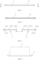
FIG. 1 is a schematic front view of a winding mandrel according to some embodiments of this application; -
FIG. 2 is a cross-sectional view along A-A inFIG. 1 ; -
FIG. 3 is a schematic exploded view of a winding mandrel according to some embodiments of this application; -
FIG. 4 is a schematic diagram of a winding mandrel in a usage state according to some embodiments of this application; -
FIG. 5 is a schematic front view of a winding mandrel according to some embodiments of this application; -
FIG. 6 is a cross-sectional view along B-B inFIG. 5 ; -
FIG. 7 is a schematic front view of a winding mandrel according to some embodiments of this application; -
FIG. 8 is a cross-sectional view along C-C inFIG. 7 ; -
FIG. 9 is a schematic exploded view of a winding mandrel according to some embodiments of this application; -
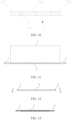
FIG. 10 is a schematic front view of a connecting rod according to some embodiments of this application; -
FIG. 11 is a schematic diagram of a winding mandrel in a usage state according to some embodiments of this application; -
FIG. 12 is a schematic front view of a winding mandrel according to some embodiments of this application; -
FIG. 13 is a cross-sectional view along D-D inFIG. 12 ; -
FIG. 14 is a schematic exploded view of a winding mandrel according to some embodiments of this application; -
FIG. 15 is a schematic front view of a hollow sleeve according to some embodiments of this application; -
FIG. 16 is a schematic diagram of a winding mandrel in a usage state according to some embodiments of this application; -
FIG. 17 is a schematic cross-sectional view of a winding mandrel according to some embodiments of this application; and -
FIG. 18 is a schematic exploded view of a winding mandrel according to some embodiments of this application. - 1. first connecting member; 101. first fixing end; 102. first body portion; 103. first combination end; 104. first connecting hole; 2. second connecting member; 201. second fixing end; 202. second body portion; 203. second combination end; 204. second connecting hole; 3. connecting rod; 301. third combination end; 302. third body portion; 303. fourth combination end; 304. first ventilation hole; 4. hollow sleeve; 401. fifth combination end; 402. fourth body portion; 403. sixth combination end; 404. second ventilation hole; and 5. diaphragm
- To make the objectives, technical solutions, and advantages of this application clearer, the following clearly and completely describes the technical solutions in the embodiments of this application with reference to the accompanying drawings showing a plurality of embodiments of this application. It should be understood that the embodiments described are only some rather than all embodiments of this application. All other embodiments obtained by persons of ordinary skill in the art based on the embodiments of this application without creative efforts shall fall within the protection scope of this application.
- Unless otherwise defined, all technical and scientific terms used in this application shall have the same meanings as commonly understood by those skilled in the art to which this application relates. The terms used in the specification of this application are intended to merely describe the specific embodiments rather than to limit this application. The terms "include", "comprise", "there be", "have", "contain", and "with" in this specification, claims, and brief description of drawings of this application are inclusive terms. Therefore, if a method or an apparatus "includes", "comprises", or "has", for example, one or more steps or elements, the method or the apparatus contains the one or more steps or elements, but is not limited to the one or more elements. In the specification, claims, or accompanying drawings of this application, the terms "first", "second", and the like are intended to distinguish between different objects rather than to indicate a particular order or relative importance. In addition, the terms "first" and "second" are merely for the purpose of description, and shall not be understood as any indication or implication of relative importance or any implicit indication of the number of technical features indicated. Therefore, a feature limited by "first" or "second" may explicitly or implicitly include one or more features. In the description of this application, "a plurality of" means at least two unless otherwise stated.
- In the descriptions of this application, it should be understood that the orientations or positional relationships indicated by the terms "center", "transverse", "length", "width", "upper", "lower", "front", "rear", "left", "right", "perpendicular", "horizontal", "top", "bottom", "inside", "outside", "axial", "radial", "circumferential", and the like are based on the orientations or positional relationships shown in the accompanying drawings. These terms are merely for ease and brevity of description of this application rather than indicating or implying that the apparatuses or components mentioned must have specific orientations or must be constructed or manipulated according to specific orientations, and therefore shall not be construed as any limitations on this application.
- In the description of this application, it should be noted that unless otherwise specified and defined explicitly, the terms "mounting", "connection", "join", and "attachment" should be understood in their general senses. For example, they may refer to a fixed connection, a detachable connection, or an integral connection, and may refer to a direct connection, an indirect connection via an intermediate medium, or an internal communication between two elements. Persons of ordinary skills in the art can understand specific meanings of these terms in this application as appropriate to specific situations.
- Reference to "embodiment" in this application means that specific features, structures, or characteristics described with reference to the embodiment may be included in at least one embodiment of this application. The word "embodiment" appearing in various places in the specification does not necessarily refer to the same embodiment or an independent or alternative embodiment that is exclusive of other embodiments. It is explicitly or implicitly understood by persons skilled in the art that the embodiments described herein may be combined with other embodiments.
- As mentioned above, it should be noted that when used in this specification, the term "include/contain" is used to clearly indicate existence of the feature, integer, step, or component, but does not exclude existence or addition of one or more other features, integers, steps, or components or sets of features, integers, steps, or components. As used in this application, singular forms "one", "a", and "the" also include plural forms, unless otherwise clearly dictated in the context.
- The terms "a" and "one" in this specification can mean a single, but can also have the same meaning as "at least one" or "one or more". The term "approximately" generally means a mentioned value plus or minus 10%, or more specifically the mentioned value plus or minus 5%. The term "or" used in the claims means "and/or" unless it is clearly stated that the term "or" only refers to an alternative solution.
- The term "and/or" in this application is only an associative relationship for describing associated objects, indicating that three relationships may be present. For example, A and/or B may indicate three cases: presence of only A; presence of both A and B; and presence of only B. In addition, the character "/" in this application generally indicates an "or" relationship between contextually associated objects.
- Working of a lithium-ion battery (a battery cell) mainly relies on migration of lithium ions between a positive electrode plate and a negative electrode plate. The lithium-ion battery uses an inserted lithium compound as an electrode material. Currently, main common materials used for a positive electrode of the lithium-ion battery include: lithium cobalt oxide (LiCoO2), lithium manganate oxide (LiMn2O4), lithium nickel oxide (LiNiO2), and lithium iron phosphate (LiFePO4). A separator is disposed between the positive electrode plate and the negative electrode plate to form a film structure with three layers of materials. The film structure is generally manufactured into a battery cell with a required shape through winding or stacking. For example, a film structure with three layers of materials in a cylindrical battery is wound into a cylindrical battery cell, and a film structure in a prismatic battery is wound or stacked into an approximately cuboid-shaped battery cell.
- The applicant has found that the size of a lithium-ion battery manufactured through winding is limited by the size of a winding mandrel, that is, a winding mandrel that is long enough is required for manufacturing a relatively long lithium-ion battery, but as only the length of the winding mandrel increases, stiffness of the winding mandrel usually fails to meet requirements. To improve stiffness of a long winding mandrel, the applicant has increased the diameter of the winding mandrel. However, after the diameter of the winding mandrel was increased, the applicant found that the winding mandrel would occupy too much volume of a battery, decreasing energy density of the battery.
- After long-term research, the applicant has designed a new winding mandrel. The winding mandrel includes a first connecting member and a second connecting member, where the second connecting member is configured to be combined with the first connecting member, the second connecting member and the first connecting member are arranged coaxially, and length of the combined first connecting member and second connecting member is greater than length of the first connecting member or the second connecting member. For the new winding mandrel, the length of the winding mandrel is increased and the stiffness of the winding mandrel is improved, which improves the efficiency and quality of a winding operation. In addition, energy density of a battery cell wound using the winding mandrel can be increased.
- For better understanding of this application, the following describes in detail the embodiments of this application with reference to
FIGs. 1 to 18 . -
FIGs. 1, 2, and 3 show a winding mandrel according to an embodiment of this application. The winding mandrel includes a first connectingmember 1 and a second connectingmember 2, where the second connectingmember 2 is configured to be combined with the first connectingmember 1, the second connectingmember 2 and the first connectingmember 1 are arranged coaxially, and length of the combined first connectingmember 1 and second connectingmember 2 is greater than length of the first connectingmember 1 or the second connectingmember 2. - The first connecting
member 1 and the second connectingmember 2 are combined coaxially to obtain a winding mandrel with the length greater than the length of the first connectingmember 1 or the second connectingmember 2, so that the overall stiffness of the winding mandrel can be improved while guaranteeing winding length of the winding mandrel without increasing the diameter of the winding mandrel, and bending deformation of the winding mandrel in a winding process is reduced, meeting requirements for winding a wide and long battery cell. In addition, the diameter of the winding mandrel is small, which can increase energy density of a battery cell wound using the winding mandrel, thereby improving the efficiency and quality of a winding operation. - In some embodiments, as shown in
FIGs. 1 and 2 , the first connectingmember 1 includes two ends along its own length direction, the second connectingmember 2 also includes two ends along its own length direction, and one end of the first connectingmember 1 along its length direction and one end of the second connectingmember 2 along its length direction are combined. - The ends of the first connecting
member 1 and the second connectingmember 2 are combined, so that it is convenient to arrange the first connectingmember 1 and the second connectingmember 2 coaxially and to limit a ratio of the lengths of the first connectingmember 1 and the second connectingmember 2 to the overall length of the winding mandrel. - As shown in
FIGs. 3 and 4 , the first connectingmember 1 includes afirst combination end 103, afirst body portion 102, and a first fixingend 101; and the second connectingmember 2 includes asecond combination end 203, asecond body portion 202, and asecond fixing end 201. A portion of the first connectingmember 1 winding the battery cell is thefirst body portion 102, and a portion of the second connectingmember 2 winding the battery cell is thesecond body portion 202. Cross sections of thefirst body portion 102 and thesecond body portion 202 are circular, elliptical, polygonal with more than three sides, polygonal with smooth transition of end angles, or flat. - Materials of the first connecting
member 1 and the second connectingmember 2 are not limited to commonly used carbon steel, carbon structural steel, high-quality structural steel, carbon tool steel, free-cutting structural steel, alloy steel, ordinary low-alloy steel, alloy steel for engineering structures, alloy steel for mechanical structures, alloy structural steel, alloy tool steel, high-speed tool steel, and the like. - In some embodiments, as shown in
FIGs. 1 and 2 , one end of the first connectingmember 1 along its length direction and one end of the second connectingmember 2 along its length direction are connected in an insertion manner.FIG. 4 shows a state of winding an electrode plate and a separator using the winding mandrel according this embodiment. Adiaphragm 5 inFIG. 4 includes a positive electrode plate, a negative electrode plate, and a separator. - The ends of the first connecting
member 1 and the second connectingmember 2 are connected in an insertion manner, so that the first connectingmember 1 and the second connectingmember 2 can support each other and form an entirety, thereby improving the overall stiffness of the winding mandrel. - The first combination end 103 of the first connecting
member 1 is provided with a conical, cylindrical, or polygonal insertion slot, and the second combination end 203 of the second connectingmember 2 is correspondingly provided with a conical, cylindrical, or polygonal plug. The provision of such insertion-connection structure facilitates coaxial arrangement of the first connectingmember 1 and second connectingmember 2. - In some embodiments, as shown in
FIGs. 5 and 6 , one end of the first connectingmember 1 along its length direction and one end of the second connectingmember 2 along its length direction are combined in a manner of being apart from each other. - The ends of the first connecting
member 1 and the second connectingmember 2 are apart from each other, so that the lengths of the first connectingmember 1 and the second connectingmember 2 can be further decreased, thereby improving the overall stiffness of the winding mandrel. Moreover, the diameters of the first connectingmember 1 and the second connectingmember 2 can be further reduced, thereby increasing energy density of the battery cell. - In some embodiments, the winding mandrel further includes an intermediate connecting member, and one end of the first connecting
member 1 along its length direction and one end of the second connectingmember 2 along its length direction are combined through the intermediate connecting member. - The ends of the first connecting
member 1 and the second connectingmember 2 are connected using the intermediate connecting member, so that the first connectingmember 1, the intermediate connecting member, and the second connectingmember 2 form an entirety and can support each other, thereby improving the overall stiffness of the winding mandrel. - When the winding mandrel is withdrawn after winding, the intermediate connecting member remains inside the battery cell, which can further support an inner circle of the battery cell, thereby maintaining a structure of the battery cell. The intermediate connecting member is made of plastic and does not affect electrical performance of the battery cell when remaining inside the battery cell.
- In some embodiments, as shown in
FIGs. 7, 8, 9 , and10 , the intermediate connecting member includes a connectingrod 3, and two ends of the connectingrod 3 are connected through insertion to one end of the first connectingmember 1 along its length direction and one end of the second connectingmember 2 along its length direction, respectively.FIG. 11 shows a state of winding an electrode plate and a separator using the winding mandrel according to this embodiment. Adiaphragm 5 inFIG. 11 includes a positive electrode plate, a negative electrode plate, and a separator. - The ends of the first connecting
member 1 and the second connectingmember 2 are connected using the connectingrod 3, so that the first connectingmember 1, the connectingrod 3, and the second connectingmember 2 form an entirety and can support each other, thereby improving the overall stiffness of the winding mandrel significantly. - As shown in
FIGs. 9 and10 , the connectingrod 3 includes athird combination end 301, athird body portion 302, and afourth combination end 303. Thethird combination end 301 is connected through insertion to the first combination end 103 of the first connectingmember 1, and thefourth combination end 303 is connected through insertion to the second combination end 203 of the second connectingmember 2. In this way, portions winding the battery cell are mainly thesecond body portion 202, thethird body portion 302, and thefirst body portion 102. - A coating that can increase a frictional force may be provided on an outer wall of the connecting
rod 3. Providing the coating can increase a frictional force between the connectingrod 3 and thediaphragm 5, which not only facilitates winding, but also can stably keep the connectingrod 3 inside the battery cell. - To facilitate insertion-connection, the
first combination end 103 and the second combination end 203 are provided with convex connection structures, respectively. Correspondingly, two ends of the connectingrod 3 are provided with concave connection structures, respectively. The provision of such insertion-connection structure facilitates coaxial arrangement of the first connectingmember 1, connectingrod 3, and second connectingmember 2. - The connecting
rod 3 is made of plastic and does not affect the electrical performance of the battery cell when remaining inside the battery cell. - In some embodiments, the connecting
rod 3 is a solid rod or a hollow rod. The connectingrod 3 shown inFIG. 9 is a hollow rod. - Either a solid or a hollow connecting
rod 3 can connect the first connectingmember 1 and the second connectingmember 2. The solidconnecting rod 3 has higher structural strength. If an electrode plate and separator to be wound are relatively wide, the solid connectingrod 3 can be used. - In some embodiments, the hollow connecting
rod 3 is provided with a plurality of first ventilation holes 304. - Because the first connecting
member 1, the second connectingmember 2, and the connectingrod 3 are closely connected, the provision of the ventilation holes facilitates insertion of the first connectingmember 1 and the second connectingmember 2 into the connectingrod 3 and prevents deformation due to an excessive pressure inside the connectingrod 3. - In some embodiments, as shown in
FIGs. 12, 13 ,14, and 15 , the intermediate connecting member includes ahollow sleeve 4, and the first connectingmember 1 and the second connectingmember 2 are inserted into thehollow sleeve 4 from two ends of thehollow sleeve 4, respectively.FIG. 16 shows a state of winding an electrode plate and a separator using the winding mandrel according to this embodiment. Adiaphragm 5 inFIG. 16 includes a positive electrode plate, a negative electrode plate, and a separator. - The first connecting
member 1 and the second connectingmember 2 are connected using thehollow sleeve 4, so that the first connectingmember 1, thehollow sleeve 4, and the second connectingmember 2 form an entirety and can support each other, thereby improving the overall stiffness of the winding mandrel significantly. - As shown in
FIGs. 14 and 15 , thehollow sleeve 4 includes afifth combination end 401, afourth body portion 402, and asixth combination end 403. In this way, a portion winding the battery cell is mainly thefourth body portion 402. - An inner wall of the
hollow sleeve 4 may be provided with a coating to reduce a frictional force generated when the first connectingmember 1 and the second connectingmember 2 are pulled out. The coating that can reduce the frictional force is provided, so that the first connectingmember 1 and the second connectingmember 2 can be easily pulled out from thehollow sleeve 4 when the winding mandrel is withdrawn after winding, which prevents thehollow sleeve 4 from being displaced and prevents the electrode plate and separator of a core from being displaced, thereby preventing the core from being pulled out and guaranteeing the quality of the battery cell. - A coating that can increase a frictional force may further be provided on an outer wall of the
hollow sleeve 4. The provision of the coating can increase a frictional force between thehollow sleeve 4 and thediaphragm 5, which not only facilitates winding, but also can stably keep thehollow sleeve 4 inside the battery cell. - In some embodiments, the first connecting
member 1 and the second connectingmember 2 are connected to or apart from each other in thehollow sleeve 4. As shown inFIGs. 12, 13 , and14 , the first connectingmember 1 and the second connectingmember 2 are connected to each other in thehollow sleeve 4. As shown inFIGs. 17 and18 , the first connectingmember 1 and the second connectingmember 2 are apart from each other in thehollow sleeve 4. - The first connecting
member 1 and the second connectingmember 2 being either connected to or apart from each other in thehollow sleeve 4 can be sleeved with thehollow sleeve 4, so that the resulting connection structure has higher strength. If an electrode plate and separator to be wound are relatively wide, the connection structure can be used. - In some embodiments, the
hollow sleeve 4 is provided with a plurality of second ventilation holes 404. - Because the first connecting
member 1, the second connectingmember 2, and thehollow sleeve 4 are closely connected, the provision of the ventilation holes facilitates insertion of the first connectingmember 1 and the second connectingmember 2 into thehollow sleeve 4 and prevents deformation due to an excessive pressure inside thehollow sleeve 4. - The
hollow sleeve 4 is made of plastic and does not affect the electrical performance of the battery cell when remaining inside the battery cell. - In some embodiments, surfaces of the first connecting
member 1 and the second connectingmember 2 are provided with coatings to reduce a frictional force generated during pull-out from the battery cell. - The coatings that can reduce the frictional force are provided, so that the first connecting
member 1 and the second connectingmember 2 can be easily pulled out from the battery cell when the winding mandrel is withdrawn after winding, which prevents the electrode plate and separator of a core from being displaced and prevents the core from being pulled out, thereby guaranteeing the quality of the battery cell. - In some embodiments, as shown in
FIG. 3 , the other end of the first connectingmember 1 along its length direction is provided with aradial connecting hole 104, the other end of the second connectingmember 2 along its length direction is also provided with aradial connecting hole 204, and the first connectingmember 1 and the second connectingmember 2 are configured to be fixed to a winding machine through the connecting holes. - The winding machine is provided with positioning pins or positioning screws corresponding to the connecting holes, and the first connecting
member 1 and the second connectingmember 2 are fixed to the winding machine through the radial connecting holes, facilitating assembly and disassembly. - According to a second aspect of this application, a winding machine is provided, including the winding mandrel according to any one of the foregoing embodiments.
- The winding mandrel according to any one of the foregoing embodiments is used, which improves stiffness of the winding mandrel, enables the winding mandrel to bear a greater centrifugal force, and makes deflection deformation not prone to occur under a high-speed rotation state, so that the acceleration, deceleration, and maximum winding speed of the winding machine can be improved, thereby improving winding efficiency and reducing production costs.
- In some embodiments, the winding machine includes a winding mandrel telescopic mechanism, and a first connecting
member 1 and a second connectingmember 2 are installed on the winding mandrel telescopic mechanism so as to be driven by the winding mandrel telescopic mechanism to approach or leave each other. - In some embodiments, the winding machine is provided with a separator pressing roller and a hook knife corresponding to the winding mandrel. The separator pressing roller and the hook knife can be driven by a driving mechanism to approach and leave the winding mandrel, respectively. When winding of an electrode plate and a separator starts, the separator pressing roller first approaches the winding mandrel to press the electrode plate and the separator to the winding mandrel. Secondly, the hook knife hooks ends of the electrode plate and separator to make the ends wound on the winding mandrel. Then, the winding mandrel performs winding at a small angle to make the electrode plate and the separator press their own ends. Finally, the hook knife and the separator pressing roller leave the winding mandrel in sequence, and the winding mandrel rotates normally to wind the electrode plate and the separator into a battery cell.
- According to a third aspect of this application, a battery cell winding method is provided, including:
- providing an electrode plate and a separator; and
- winding the electrode plate and the separator using a winding mandrel, where the winding mandrel is the winding mandrel according to any one of the foregoing embodiments.
- In conclusion, it should be noted that the foregoing embodiments are merely intended for describing the technical solutions of this application, but not for limiting this application. Although this application is described in detail with reference to the foregoing embodiments, persons of ordinary skills in the art should understand that they may still make modifications to the technical solutions described in the foregoing embodiments or make equivalent replacements to some technical features thereof, without departing from the spirit and scope of the technical solutions of the embodiments of this application.
Claims (15)
- A winding mandrel, configured to wind a battery cell, comprising:a first connecting member; anda second connecting member configured to be combined with the first connecting member, wherein the second connecting member and the first connecting member are arranged coaxially, and length of the combined first connecting member and second connecting member is greater than length of the first connecting member or the second connecting member.
- The winding mandrel according to claim 1, wherein the first connecting member comprises two ends along its own length direction; the second connecting member also comprises two ends along its own length direction; and one end of the first connecting member along its length direction and one end of the second connecting member along its length direction are combined.
- The winding mandrel according to claim 2, wherein one end of the first connecting member along its length direction and one end of the second connecting member along its length direction are connected in an insertion manner.
- The winding mandrel according to claim 2, wherein one end of the first connecting member along its length direction and one end of the second connecting member along its length direction are combined in a manner of being apart from each other.
- The winding mandrel according to claim 2, wherein the winding mandrel further comprises an intermediate connecting member, and one end of the first connecting member along its length direction and one end of the second connecting member along its length direction are combined through the intermediate connecting member.
- The winding mandrel according to claim 5, wherein the intermediate connecting member comprises a connecting rod, and two ends of the connecting rod are connected through insertion to one end of the first connecting member along its length direction and one end of the second connecting member along its length direction, respectively.
- The winding mandrel according to claim 6, wherein the connecting rod is a solid rod or a hollow rod.
- The winding mandrel according to claim 5, wherein the intermediate connecting member comprises a hollow sleeve, and the first connecting member and the second connecting member are inserted into the hollow sleeve from two ends of the hollow sleeve, respectively.
- The winding mandrel according to claim 8, wherein the first connecting member and the second connecting member are connected to or apart from each other in the hollow sleeve.
- The winding mandrel according to claim 8 or 9, wherein the hollow sleeve is provided with a plurality of ventilation holes.
- The winding mandrel according to any one of claims 1 to 10, wherein surfaces of the first connecting member and the second connecting member are provided with coatings to reduce a frictional force generated during pull-out from the battery cell.
- The winding mandrel according to any one of claims 2 to 10, wherein the other end of the first connecting member along its length direction is provided with a radial connecting hole; the other end of the second connecting member along its length direction is also provided with a radial connecting hole; and the first connecting member and the second connecting member are configured to be fixed to a winding machine through the connecting holes.
- A winding machine, comprising the winding mandrel according to any one of claims 1 to 12.
- The winding machine according to claim 13, wherein the winding machine comprises a winding mandrel telescopic mechanism, and the first connecting member and the second connecting member are installed on the winding mandrel telescopic mechanism so as to be driven by the winding mandrel telescopic mechanism to approach or leave each other.
- A battery cell winding method, comprising:providing an electrode plate and a separator; andwinding the electrode plate and the separator using a winding mandrel, wherein the winding mandrel is the winding mandrel according to any one of claims 1 to 12.
Applications Claiming Priority (2)
| Application Number | Priority Date | Filing Date | Title |
|---|---|---|---|
| CN202210044920.8A CN116487727A (en) | 2022-01-14 | 2022-01-14 | A kind of winding needle, winding machine, electric core winding method |
| PCT/CN2023/070740 WO2023134543A1 (en) | 2022-01-14 | 2023-01-05 | Winding needle, winding machine, battery cell winding method |
Publications (2)
| Publication Number | Publication Date |
|---|---|
| EP4398374A1 true EP4398374A1 (en) | 2024-07-10 |
| EP4398374A4 EP4398374A4 (en) | 2025-10-15 |
Family
ID=87223730
Family Applications (1)
| Application Number | Title | Priority Date | Filing Date |
|---|---|---|---|
| EP23739887.0A Pending EP4398374A4 (en) | 2022-01-14 | 2023-01-05 | WINDING NEEDLE, WINDING MACHINE, BATTERY CELL WINDING PROCESS |
Country Status (4)
| Country | Link |
|---|---|
| US (1) | US20240317528A1 (en) |
| EP (1) | EP4398374A4 (en) |
| CN (2) | CN116487727A (en) |
| WO (1) | WO2023134543A1 (en) |
Families Citing this family (2)
| Publication number | Priority date | Publication date | Assignee | Title |
|---|---|---|---|---|
| KR20250019799A (en) * | 2023-08-02 | 2025-02-11 | 이계설 | Core for secondary battery separator film winding |
| CN223123925U (en) * | 2024-08-15 | 2025-07-18 | 宁德时代新能源科技股份有限公司 | Winding needle structure, winding equipment and battery cell |
Family Cites Families (16)
| Publication number | Priority date | Publication date | Assignee | Title |
|---|---|---|---|---|
| JPH07269534A (en) * | 1994-03-29 | 1995-10-17 | Nitto Seiko Co Ltd | Mounting bracket for rod-shaped parts |
| CN201060905Y (en) * | 2007-07-13 | 2008-05-14 | 深圳市高威仕科技有限公司 | Battery core winding needle and its fixation structure |
| CN201868529U (en) * | 2010-11-06 | 2011-06-15 | 合肥国轩高科动力能源有限公司 | Needle winding device for battery cell winding and hollow support tube used in conjunction with the winding needle |
| KR101965707B1 (en) * | 2012-11-01 | 2019-04-05 | 삼성에스디아이 주식회사 | Winder for electrode assembly of rechargeable battery |
| KR101878601B1 (en) * | 2017-05-08 | 2018-07-16 | 황광성 | Pipe joint, apparatus for producing the same and method for constructing piping system using the same |
| CN207074691U (en) * | 2017-07-24 | 2018-03-06 | 东莞市创明电池技术有限公司 | A cylindrical battery winding mechanism |
| CN207233878U (en) * | 2017-09-28 | 2018-04-13 | 广东国光电子有限公司 | A kind of new volume pin |
| CN209691867U (en) * | 2019-05-09 | 2019-11-26 | 深圳市诚捷智能装备股份有限公司 | Rolling needle mechanism, winding apparatus and battery winder |
| CN210092239U (en) * | 2019-07-10 | 2020-02-18 | 广州凯风电容器有限公司 | Positioning and supporting device of nailing and rolling machine |
| CN110984479B (en) * | 2019-12-21 | 2021-07-06 | 东莞市鸿宇世纪建设工程有限公司 | Construction structure for induced joint and construction method of induced joint |
| CN211858815U (en) * | 2020-04-30 | 2020-11-03 | 诚捷智能装备(东莞)有限公司 | Winding needle structure and winding machine |
| CN112928339B (en) * | 2021-03-09 | 2022-12-02 | 东莞泓宇智能装备有限公司 | Ultra-small distance winding needle structure of lithium battery sheet-making winding machine |
| CN215118997U (en) * | 2021-03-27 | 2021-12-10 | 深圳市精诚信五金机械有限公司 | Square winding needle for winding type battery pole core |
| CN215578687U (en) * | 2021-07-20 | 2022-01-18 | 河北银隆新能源有限公司 | Cell winding device |
| CN215418295U (en) * | 2021-07-30 | 2022-01-04 | 宁德时代新能源科技股份有限公司 | Needle rolling sleeves, battery cells, batteries, electrical devices and winding devices |
| CN218241930U (en) * | 2022-06-16 | 2023-01-06 | 广东利元亨智能装备股份有限公司 | Roll up needle mechanism and winder |
-
2022
- 2022-01-14 CN CN202210044920.8A patent/CN116487727A/en active Pending
-
2023
- 2023-01-05 CN CN202390000165.1U patent/CN222355181U/en active Active
- 2023-01-05 EP EP23739887.0A patent/EP4398374A4/en active Pending
- 2023-01-05 WO PCT/CN2023/070740 patent/WO2023134543A1/en not_active Ceased
-
2024
- 2024-06-06 US US18/735,198 patent/US20240317528A1/en active Pending
Also Published As
| Publication number | Publication date |
|---|---|
| US20240317528A1 (en) | 2024-09-26 |
| WO2023134543A1 (en) | 2023-07-20 |
| CN222355181U (en) | 2025-01-14 |
| CN116487727A (en) | 2023-07-25 |
| EP4398374A4 (en) | 2025-10-15 |
Similar Documents
| Publication | Publication Date | Title |
|---|---|---|
| US20240317528A1 (en) | Winding mandrel, winding machine, and battery cell winding method | |
| JP4789584B2 (en) | Method for manufacturing a secondary battery having a flat spiral electrode body | |
| CN215418295U (en) | Needle rolling sleeves, battery cells, batteries, electrical devices and winding devices | |
| CN220086320U (en) | Battery cells, batteries and electrical devices | |
| CN216749959U (en) | Electrode assemblies, battery cells, batteries and electrical devices | |
| CN220914293U (en) | Coiled battery cell of battery cell, battery pack and electricity utilization device | |
| CN218996796U (en) | Positioning member, electrode assembly winding apparatus, and battery manufacturing apparatus | |
| WO2024045276A1 (en) | Battery cell, battery, and electric device | |
| CN223123925U (en) | Winding needle structure, winding equipment and battery cell | |
| CN118610601B (en) | Battery cell, battery device, electricity utilization device and preparation method of electrode assembly | |
| CN215578687U (en) | Cell winding device | |
| CN219575722U (en) | Full-tab winding core and lithium ion battery thereof | |
| CN118040007A (en) | Rolling core and small lithium metal battery for electronic atomizer and manufacturing method thereof | |
| CN116315324A (en) | Cells, batteries and electrical equipment | |
| EP4425625B1 (en) | Positioning member, winding device for electrode assembly, and battery manufacturing device | |
| CN221102174U (en) | Battery cell | |
| US20260001737A1 (en) | Winding needle assembly, winding apparatus, production device, and method for winding electrode assemblies | |
| CN219066847U (en) | Pole piece preparation device | |
| CN119481345B (en) | Secondary battery and electric equipment | |
| CN221551958U (en) | Lithium battery cell structure | |
| JP3253831U (en) | Winding core assembly and wound battery | |
| CN223193817U (en) | Pole piece structure, lamination electric core and battery | |
| CN220914307U (en) | Battery cell, battery device and electric equipment | |
| CN221486585U (en) | Winding needle, pole piece winding device and battery manufacturing equipment | |
| CN222106760U (en) | A pole piece structure, battery cell and battery |
Legal Events
| Date | Code | Title | Description |
|---|---|---|---|
| STAA | Information on the status of an ep patent application or granted ep patent |
Free format text: STATUS: THE INTERNATIONAL PUBLICATION HAS BEEN MADE |
|
| PUAI | Public reference made under article 153(3) epc to a published international application that has entered the european phase |
Free format text: ORIGINAL CODE: 0009012 |
|
| STAA | Information on the status of an ep patent application or granted ep patent |
Free format text: STATUS: REQUEST FOR EXAMINATION WAS MADE |
|
| 17P | Request for examination filed |
Effective date: 20240405 |
|
| AK | Designated contracting states |
Kind code of ref document: A1 Designated state(s): AL AT BE BG CH CY CZ DE DK EE ES FI FR GB GR HR HU IE IS IT LI LT LU LV MC ME MK MT NL NO PL PT RO RS SE SI SK SM TR |
|
| RAP1 | Party data changed (applicant data changed or rights of an application transferred) |
Owner name: CONTEMPORARY AMPEREX TECHNOLOGY(HONG KONG) LIMITED |
|
| DAV | Request for validation of the european patent (deleted) | ||
| DAX | Request for extension of the european patent (deleted) | ||
| A4 | Supplementary search report drawn up and despatched |
Effective date: 20250912 |
|
| RIC1 | Information provided on ipc code assigned before grant |
Ipc: H01M 10/0587 20100101AFI20250908BHEP Ipc: H01M 10/0525 20100101ALI20250908BHEP Ipc: H01M 10/04 20060101ALI20250908BHEP |