EP4398323A1 - Flattening device - Google Patents
Flattening device Download PDFInfo
- Publication number
- EP4398323A1 EP4398323A1 EP22941335.6A EP22941335A EP4398323A1 EP 4398323 A1 EP4398323 A1 EP 4398323A1 EP 22941335 A EP22941335 A EP 22941335A EP 4398323 A1 EP4398323 A1 EP 4398323A1
- Authority
- EP
- European Patent Office
- Prior art keywords
- sleeves
- main roller
- electrode plate
- flattening device
- axial direction
- Prior art date
- Legal status (The legal status is an assumption and is not a legal conclusion. Google has not performed a legal analysis and makes no representation as to the accuracy of the status listed.)
- Pending
Links
Images




Classifications
-
- B—PERFORMING OPERATIONS; TRANSPORTING
- B21—MECHANICAL METAL-WORKING WITHOUT ESSENTIALLY REMOVING MATERIAL; PUNCHING METAL
- B21D—WORKING OR PROCESSING OF SHEET METAL OR METAL TUBES, RODS OR PROFILES WITHOUT ESSENTIALLY REMOVING MATERIAL; PUNCHING METAL
- B21D1/00—Straightening, restoring form or removing local distortions of sheet metal or specific articles made therefrom; Stretching sheet metal combined with rolling
- B21D1/02—Straightening, restoring form or removing local distortions of sheet metal or specific articles made therefrom; Stretching sheet metal combined with rolling by rollers
-
- B—PERFORMING OPERATIONS; TRANSPORTING
- B21—MECHANICAL METAL-WORKING WITHOUT ESSENTIALLY REMOVING MATERIAL; PUNCHING METAL
- B21D—WORKING OR PROCESSING OF SHEET METAL OR METAL TUBES, RODS OR PROFILES WITHOUT ESSENTIALLY REMOVING MATERIAL; PUNCHING METAL
- B21D37/00—Tools as parts of machines covered by this subclass
- B21D37/04—Movable or exchangeable mountings for tools
-
- H—ELECTRICITY
- H01—ELECTRIC ELEMENTS
- H01M—PROCESSES OR MEANS, e.g. BATTERIES, FOR THE DIRECT CONVERSION OF CHEMICAL ENERGY INTO ELECTRICAL ENERGY
- H01M4/00—Electrodes
- H01M4/02—Electrodes composed of, or comprising, active material
- H01M4/04—Processes of manufacture in general
- H01M4/043—Processes of manufacture in general involving compressing or compaction
- H01M4/0435—Rolling or calendering
-
- Y—GENERAL TAGGING OF NEW TECHNOLOGICAL DEVELOPMENTS; GENERAL TAGGING OF CROSS-SECTIONAL TECHNOLOGIES SPANNING OVER SEVERAL SECTIONS OF THE IPC; TECHNICAL SUBJECTS COVERED BY FORMER USPC CROSS-REFERENCE ART COLLECTIONS [XRACs] AND DIGESTS
- Y02—TECHNOLOGIES OR APPLICATIONS FOR MITIGATION OR ADAPTATION AGAINST CLIMATE CHANGE
- Y02E—REDUCTION OF GREENHOUSE GAS [GHG] EMISSIONS, RELATED TO ENERGY GENERATION, TRANSMISSION OR DISTRIBUTION
- Y02E60/00—Enabling technologies; Technologies with a potential or indirect contribution to GHG emissions mitigation
- Y02E60/10—Energy storage using batteries
Definitions
- a battery is an important device for storing electrical energy.
- An electrode plate is an important component of a lithium battery.
- a slurry containing an electrode active material can coat on one or two sides of the electrode plate, so that the electrode plate can be divided into a film-coating region and a blank region (electrode tab region).
- a portion coated with the electrode active material may be the film-coating region, and a portion not coated with the electrode active material may be the blank region.
- the flattening device may include a main roller and a plurality of sleeves.
- the plurality of sleeves are sleeved on the main roller at intervals in an axial direction of the main roller.
- At least one of the sleeves is detachably connected to the main roller, so that positions of the sleeves in the axial direction of the main roller are adjustable, and the sleeves are in contact with the electrode plate to flatten the electrode plate when the electrode plate passes through the sleeves.
- the electrode plate can be flattened and wrinkled through the sleeves, so that it can improve the yield of the electrode plate.
- the sleeves can be detachably connected to the main roller, the electrode plate can be flattened using the main roller alone, or the sleeves can be sleeved on the main roller for flattening.
- the sleeves can flatten both a film-coating region and a blank region.
- By sleeving the plurality of sleeves at intervals in the axial direction of the main roller it can be applied to the electrode plate with a plurality of blank regions and a plurality of film-coating regions, and simultaneously it can flatten the plurality of film-coating regions or blank regions.
- a distance between any two sleeves can be adjusted, and the distance between sleeves can be adjusted.
- the distance between the sleeves can be adjusted according to a width between the blank regions or the film-coating regions, so that different types of the electrode plates can be flattened, so as to improve the compatibility of the flattening device.
- At least two sleeves have different dimensions in the axial direction, and corresponding sleeves can be selected based on the width of the film-coating region or blank region which is flattened as needed; and/or, at least two sleeves have different surface patterns, and the sleeves with the corresponding surface patterns can be selected based on the specific wrinkling situations, so as to improve an application scope of the flattening device.
- a plurality of first protruding parts can be provided, and the plurality of first protruding parts are arranged at intervals in a circumferential direction of the sleeve main body.
- the main roller drives the sleeves to rotate, since the plurality of first protruding parts are arranged at intervals in the circumferential direction, each of the plurality of first protruding parts can be in contact with the electrode plate, so that the force on the electrode plate can be more uniform.
- the first protruding part can extend in the axial direction.
- a contact area between the first protruding parts and the electrode plate is large, so that it can improve the wrinkle-removing effect.
- an extending direction of the first protruding part is inclined relative to the axial direction. If there is a difference in height between two sides of the electrode plate in a width direction thereof, or if thicknesses of the film-coating region of the electrode plate are inconsistent, it will lead to an offset phenomenon during the electrode plate moving.
- the sleeves with the first protruding part whose extending direction is inclined relative to the axial direction of the main roller can not only achieve the wrinkle-removing and flattening effect, but also have a certain deflection-correcting effect on the electrode plate, so that the electrode plate can move in a predetermined direction.
- an inclined angle of the extending direction of the first protruding part relative to the axial direction is in a range of 1°-80°. If the inclined angle of the extending direction of the first protruding part relative to the axial direction of the main roller is too small, the deflection-correcting effect may not be obvious; if the inclined angle of the extending direction of the first protruding part relative to the axial direction of the main roller is too large, the excessive deflection-correcting effect may occur. Therefore, the inclined angle can be selected from 1° to 80°, so that it cannot only ensure the deflection-correcting effect on the electrode plate that has moved and offset, but also avoid the phenomenon that the electrode plate offsets again due to the excessive deflection-correcting effect.
- the flattening device may include two sleeves. Extending directions of the first protruding parts of the two sleeves are arranged at an angle, and the two sleeves are symmetrically sleeved on the main roller. The inclination directions of the first protruding parts of the two sleeves may be opposite to each other, and the forces exerted by the first protruding parts of the two sleeves on the electrode plate is exactly opposite to each other, so that it can prevent the electrode plate from offsetting during movement and cause the electrode plate to move in the predetermined direction.
- At least one of the sleeves may include at least two arc segments sequentially distributed in the axial direction, the at least two arc segments are protruded, and an outer surface of each of the arc segments is an arc surface with the same curvature.
- the plurality of arc segments protruding outward can increase the friction force between the sleeves and the electrode plate, thereby improving the flattening effect.
- At least one of the sleeves may include a first segment and a second segment sequentially distributed in the axial direction, the first segment and the second segment are arranged to gradually expand toward directions close to each other respectively, and the sleeves are sleeved on a middle region of the main roller. Since the electrode plate is relatively thin, during the movement of the electrode plate, the electrode plate is generally in a state that is high on two sides and depressed downward in the middle during the movement of the electrode plate, so that it is prone to wrinkle.
- the sleeves can be arranged in the middle region of the main roller, corresponding to the region depressed downward in the middle of the electrode plate. Since at least one of the sleeves may be in a shape which is high in the middle and low at two ends, the sleeves can lift up a depressed portion of the electrode plate, so as to prevent the electrode plate from wrinkling.
- the flattening device may further include an expansion structure arranged between the main roller and the sleeves.
- the main roller can be detachably connected to the sleeves through the expansion structure.
- the sleeves can be tightly sleeved on the main roller through the expansion of the expansion structure.
- the power battery is not only used in an energy storage power system such as a hydropower, firepower, wind power or solar power plant and the like, but also widely used in an electric vehicle such as an electric bicycle, an electric motorcycle, an electric vehicle and the like, as well as in various fields such as military equipment, aerospace and the like.
- an energy storage power system such as a hydropower, firepower, wind power or solar power plant and the like
- an electric vehicle such as an electric bicycle, an electric motorcycle, an electric vehicle and the like
- the market demand thereof is also constantly expanding.
- the position of the sleeve on the main roller can be adjusted in an axial direction of the main roller, and a plurality of sleeves can be arranged at intervals in the axial direction of the main roller, so that it can be applied to the electrode plates with a plurality of blank regions and a plurality of film-coating regions, while flattening the plurality of film-coating regions or the plurality of blank regions. Since a distance between any two sleeves can be adjusted, the distance between the sleeves can be adjusted according to the width between the blank regions or the film-coating regions, so as to flatten different types of electrode plates, so that the compatibility of the flattening device can be improved.
- the flattening device described in embodiments of the present application is applicable to an electrode plate flattening device and the electrode plate forming device using the electrode plate flattening device.
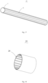
- Fig. 3 shows a structural schematic view of the main roller 10 according to some embodiments of the present application
- Fig. 4 shows a structural schematic view of the main roller 10 according to some other embodiments of the present application.
- the main roller 10 can be a cylindrical roller as shown in Fig. 3 or a prism roller as shown in Fig. 4 .
- the main roller 10 can prevent the sleeves 20 from rotating relative to one another after being sleeved on an outer side of the main roller 10.
- the main roller 10 can also be an arc-shaped roller.
- the main roller 10 can be used separately to flatten the film-coating region 31 of the electrode plate 30.
- the main roller 10 by detachably connecting the sleeve 20 with the main roller 10, the main roller 10 can be used separately to flatten the electrode plate 30, or the sleeve 20 can be sleeved on the main roller 10 to flatten the electrode plate 30.
- the sleeve 20 can flatten both the film-coating region 31 and the blank region 32.
- At least two sleeves 20 have different dimensions in the axial direction. Due to differences in the widths of different film-coating regions 31 or the blank regions 32 on the same electrode plate 30, or differences in the widths of film-coating regions 31 or the blank regions 32 of different types of the electrode plates 30, the dimensions of the at least two sleeves 20 in the axial direction of the main roller 10 can be set differently, that is, the length dimensions of the at least two sleeves 20 are different.
- the sleeves 20 with corresponding length dimensions can be selected based on the specific widths of the film-coating regions 31 or the blank regions 32, so that it can improve the application scope of the flattening device 100.
- At least two sleeves 20 have different surface patterns.
- Fig. 5 shows a structural schematic view of the sleeve 20 according to some embodiments of the present application
- Fig. 6 shows a structural schematic view of the sleeve 20 according to some other embodiments of the present application.
- the sleeve 20 can be a cylindrical sleeve as shown in Fig. 5 and Fig. 6 , or an arc-shaped sleeve.
- the outer surface of sleeve 20 can be smooth face or formed the pattern, so as to increase the friction force between sleeve 20 and electrode plate 30 and improve the wrinkle-removing effect. Different patterns can correspond to different wrinkle situations.
- the patterns on the outer surfaces of at least two sleeves 20 are arranged to be different, so that it can flatten the electrode plates 30 in the different wrinkled situations and improve the application scope of the flattening device 100.
- Fig. 7 shows a structural schematic view of the sleeve 20 according to some other embodiments of the present application.
- At least one of the sleeves 20 may include a sleeve main body 21 and a first protruding part 22, the sleeve main body 21 can be sleeved on the main roller 10 and detachably connected to the main roller 10, and the first protruding part 22 may protrude from an outer surface of the sleeve main body 21.
- a plurality of first protruding parts 22 can be provided, and the plurality of first protruding parts 22 are arranged at intervals in a circumferential direction of the sleeve main body 21.
- the first protruding parts 22 can be evenly arranged on an outer circumference of the sleeve main body 21 at intervals.
- the spacing distance between the first protruding parts 22 can be determined as needed.
- the dense arrangement of the first protruding parts 22 is more conducive to increasing the wrinkle-removing effect.
- the first protruding parts 22 can also be detachably fixed to the sleeve main body 21 to adjust the spacing distance between the first protruding parts 22.
- a groove 26 can be formed on the outer surface of the sleeve main body 21, and the first protruding parts 22 can be engaged with the groove 26 to achieve sliding the first protruding parts 22 in the groove 26.
- first protruding part 22 By sliding the first protruding part 22 along the groove 26, the distance between the two first protruding parts 22 can be adjusted. It is also possible to set the number of first protruding parts 22 on the sleeve main body 21 as needed to adjust the friction force between the sleeves 20 and the electrode plate 30.
- each of the plurality of first protruding parts 22 can be in contact with the electrode plate 30, so that it not only can increase the frictional force between the sleeve 20 and the electrode plate 30, but also can make the force on the electrode plate 30 more uniform, thereby improving the wrinkle-removing effect and flattening effect.
Landscapes
- Engineering & Computer Science (AREA)
- Mechanical Engineering (AREA)
- Manufacturing & Machinery (AREA)
- Chemical & Material Sciences (AREA)
- Chemical Kinetics & Catalysis (AREA)
- Electrochemistry (AREA)
- General Chemical & Material Sciences (AREA)
- Battery Electrode And Active Subsutance (AREA)
- Registering, Tensioning, Guiding Webs, And Rollers Therefor (AREA)
- Coating Apparatus (AREA)
Abstract
Description
- This application claims priority to
Chinese Patent Application No. 202221128220.9, titled "FLATTENING DEVICE" and filed on May 12, 2022 - The present application relates to the technical field of batteries, and in particular to a flattening device.
- A battery is an important device for storing electrical energy. An electrode plate is an important component of a lithium battery. During production, a slurry containing an electrode active material can coat on one or two sides of the electrode plate, so that the electrode plate can be divided into a film-coating region and a blank region (electrode tab region). Herein, a portion coated with the electrode active material may be the film-coating region, and a portion not coated with the electrode active material may be the blank region.
- During a transmission process of all process steps (coating, rolling, winding and the like), the electrode plate is prone to wrinkle, so that it may affect the yield of the electrode plate.
- A flattening device is provided by embodiments of the present application, which can flatten the wrinkle of an electrode plate and improve the yield of the electrode plate.
- The flattening device provided by embodiments of the present application may include a main roller and a plurality of sleeves. The plurality of sleeves are sleeved on the main roller at intervals in an axial direction of the main roller. At least one of the sleeves is detachably connected to the main roller, so that positions of the sleeves in the axial direction of the main roller are adjustable, and the sleeves are in contact with the electrode plate to flatten the electrode plate when the electrode plate passes through the sleeves.
- The electrode plate can be flattened and wrinkled through the sleeves, so that it can improve the yield of the electrode plate. The sleeves can be detachably connected to the main roller, the electrode plate can be flattened using the main roller alone, or the sleeves can be sleeved on the main roller for flattening. The sleeves can flatten both a film-coating region and a blank region. By sleeving the plurality of sleeves at intervals in the axial direction of the main roller, it can be applied to the electrode plate with a plurality of blank regions and a plurality of film-coating regions, and simultaneously it can flatten the plurality of film-coating regions or blank regions. A distance between any two sleeves can be adjusted, and the distance between sleeves can be adjusted. The distance between the sleeves can be adjusted according to a width between the blank regions or the film-coating regions, so that different types of the electrode plates can be flattened, so as to improve the compatibility of the flattening device.
- In some embodiments, at least two sleeves have different dimensions in the axial direction, and corresponding sleeves can be selected based on the width of the film-coating region or blank region which is flattened as needed; and/or, at least two sleeves have different surface patterns, and the sleeves with the corresponding surface patterns can be selected based on the specific wrinkling situations, so as to improve an application scope of the flattening device.
- In some embodiments, at least one of the sleeves may include a sleeve main body and a first protruding part, the sleeve main body can be sleeved on the main roller and detachably connected to the main roller, and the first protruding part protrudes from an outer surface of the sleeve main body. The arrangement of the first protruding part can increase a frictional force between the sleeves and the electrode plate, so as to improve the flattening effect.
- In some embodiments, a plurality of first protruding parts can be provided, and the plurality of first protruding parts are arranged at intervals in a circumferential direction of the sleeve main body. When the main roller drives the sleeves to rotate, since the plurality of first protruding parts are arranged at intervals in the circumferential direction, each of the plurality of first protruding parts can be in contact with the electrode plate, so that the force on the electrode plate can be more uniform.
- In some embodiments, the first protruding part can extend in the axial direction. A contact area between the first protruding parts and the electrode plate is large, so that it can improve the wrinkle-removing effect.
- In some embodiments, an extending direction of the first protruding part is inclined relative to the axial direction. If there is a difference in height between two sides of the electrode plate in a width direction thereof, or if thicknesses of the film-coating region of the electrode plate are inconsistent, it will lead to an offset phenomenon during the electrode plate moving. The sleeves with the first protruding part whose extending direction is inclined relative to the axial direction of the main roller can not only achieve the wrinkle-removing and flattening effect, but also have a certain deflection-correcting effect on the electrode plate, so that the electrode plate can move in a predetermined direction.
- In some embodiments, an inclined angle of the extending direction of the first protruding part relative to the axial direction is in a range of 1°-80°. If the inclined angle of the extending direction of the first protruding part relative to the axial direction of the main roller is too small, the deflection-correcting effect may not be obvious; if the inclined angle of the extending direction of the first protruding part relative to the axial direction of the main roller is too large, the excessive deflection-correcting effect may occur. Therefore, the inclined angle can be selected from 1° to 80°, so that it cannot only ensure the deflection-correcting effect on the electrode plate that has moved and offset, but also avoid the phenomenon that the electrode plate offsets again due to the excessive deflection-correcting effect.
- In some embodiments, the first protruding part extends in a spiral shape. The helical first protruding part also has direction guidance for the electrode plate, so that it can achieve the deviation-correcting effect.
- In some embodiments, the flattening device may include two sleeves. Extending directions of the first protruding parts of the two sleeves are arranged at an angle, and the two sleeves are symmetrically sleeved on the main roller. The inclination directions of the first protruding parts of the two sleeves may be opposite to each other, and the forces exerted by the first protruding parts of the two sleeves on the electrode plate is exactly opposite to each other, so that it can prevent the electrode plate from offsetting during movement and cause the electrode plate to move in the predetermined direction.
- In some embodiments, at least one of the sleeves may include at least two arc segments sequentially distributed in the axial direction, the at least two arc segments are protruded, and an outer surface of each of the arc segments is an arc surface with the same curvature. The plurality of arc segments protruding outward can increase the friction force between the sleeves and the electrode plate, thereby improving the flattening effect.
- In some embodiments, at least one of the sleeves may include a first segment and a second segment sequentially distributed in the axial direction, the first segment and the second segment are arranged to gradually expand toward directions close to each other respectively, and the sleeves are sleeved on a middle region of the main roller. Since the electrode plate is relatively thin, during the movement of the electrode plate, the electrode plate is generally in a state that is high on two sides and depressed downward in the middle during the movement of the electrode plate, so that it is prone to wrinkle. The sleeves can be arranged in the middle region of the main roller, corresponding to the region depressed downward in the middle of the electrode plate. Since at least one of the sleeves may be in a shape which is high in the middle and low at two ends, the sleeves can lift up a depressed portion of the electrode plate, so as to prevent the electrode plate from wrinkling.
- In some embodiments, the sleeves may be elastic sleeves. The elastic sleeves not only have the advantage of light weight, but also have a certain degree of flexibility, so that it can protect the electrode plate and prevent the electrode plate from being damaged.
- In some embodiments, the main roller may include a roller body and a plurality of second protruding parts, each of the second protruding parts may protrude from an outer surface of the roller body, and an inner surface of at least one of the sleeves may be provided with grooves engaged with the second protruding parts. By the engagement cooperation between the second protruding parts and the grooves, the sleeves can be sleeved on the outer surface of the main roller, and the sleeves can slide relative to the main roller to realize the position adjustment of the sleeves.
- In some embodiments, the flattening device may further include an expansion structure arranged between the main roller and the sleeves. The main roller can be detachably connected to the sleeves through the expansion structure. The sleeves can be tightly sleeved on the main roller through the expansion of the expansion structure. When it is necessary to adjust the position of the sleeves or disassemble the sleeves, only the pressure relief of the expansion structure is needed to form a gap between the sleeves and the main roller, and the sleeves and the main roller can be separated from each other.
- The above description is only an overview of the technical solution of the present application. In order to have a clearer understanding of the technical solution of the present application, it can be implemented according to the content of the description, and in order to make the above and other purposes, features and advantages of the present application more obvious and understandable, the specific embodiments of the present application will be listed below.
- In order to more clearly illustrate the technical solutions of the embodiments of the present application, the drawings to be used in the description of the embodiments of the present application will be described briefly below. Obviously, the drawings in the following description are merely some embodiments of the present application. For those skilled in the art, other drawings can also be obtained according to these drawings without the inventive labor.
-
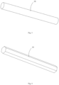
Fig. 1 shows a structural schematic view of an electrode plate according to some embodiments of the present application; -
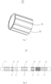
Fig. 2 shows a structural schematic view of a flattening device according to some embodiments of the present application; -
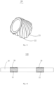
Fig. 3 shows a structural schematic view of a main roller according to some embodiments of the present application; -
Fig. 4 shows a structural schematic view of a main roller according to some other embodiments of the present application; -
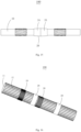
Fig. 5 shows a structural schematic view of a sleeve according to some embodiments of the present application; -
Fig. 6 shows a structural schematic view of a sleeve according to some other embodiments of the present application; -
Fig. 7 shows a structural schematic view of a sleeve according to some other embodiments of the present application; -
Fig. 8 shows a structural schematic view of a flattening device according to some other embodiments of the present application; -
Fig. 9 shows a structural schematic view of a flattening device according to some other embodiments of the present application; -
Fig. 10 shows a structural schematic view of a sleeve according to some other embodiments of the present application; -
Fig. 11 shows a structural schematic view of a sleeve according to some other embodiments of the present application; -
Fig. 12 shows a structural schematic view of a flattening device according to some other embodiments of the present application; -
Fig. 13 shows a structural schematic view of a sleeve according to some other embodiments of the present application; -
Fig. 14 shows a structural schematic view of a sleeve according to some other embodiments of the present application; -
Fig. 15 shows a structural schematic view of a flattening device according to some other embodiments of the present application; -
Fig. 16 shows a structural schematic view of a flattening device according to some other embodiments of the present application; -
Fig. 17 shows a structural schematic view of a main roller according to some other embodiments of the present application; and -
Fig. 18 shows a structural schematic view of a sleeve according to some other embodiments of the present application. - In the drawings: 100-flattening device; 10-main roller; 11-roller body; 12-second protruding part; 20- sleeve; 21-sleeve main body; 22-first protruding part; 23-arc segment; 24-first segment; 25-second segment; 26-groove; 30-electrode plate; 31-film-coating region; 32-blank region.
- The embodiments of the present application will be described in further detail below conjunction with the drawings and the embodiments. The detailed description and drawings of the following embodiments are used to exemplarily illustrate the principle of the present application, but cannot be used to limit the scope of the present application, in other words, the present application is not limited to the described embodiments.
- In the description of the present application, it should be noted that, unless otherwise specified, "plurality" means more than two; the terms "upper", "lower", "left", "right", "inner", "outer", etc. indicate the orientation or positional relationship only for the convenience of describing the present application and simplifying the description, rather than indicating or implying that the device or the element referred to must have a specific orientation, be configured and operated in a specific orientation, and therefore cannot be understood as a limitation of the present application. In addition, the terms "first", "second", "third", etc. are only used for descriptive purposes, and cannot be understood as indicating or implying relative importance. The term "perpendicular" does not mean strictly perpendicular, but within the allowable range of error. The term "parallel" does not mean strictly parallel, but within the allowable range of error.
- The orientation words appearing in the following description are all directions shown in the drawings, and do not limit the specific structure of the present application. In the description of the present application, it should also be noted that, unless otherwise clearly specified and limited, the terms "installed", "connecting" and "connected" should be understood in a broad sense, for example, it can be a fixed connection, a detachable connection, or an integral connection, it can be a direct connection, or it can be connected indirectly through an intermediary. For those of ordinary skill in the art, the specific meaning of the above-mentioned terms in the present application can be understood according to specific situations.
- At present, based on the development of the market situation, the application of a power battery is becoming increasingly widespread. The power battery is not only used in an energy storage power system such as a hydropower, firepower, wind power or solar power plant and the like, but also widely used in an electric vehicle such as an electric bicycle, an electric motorcycle, an electric vehicle and the like, as well as in various fields such as military equipment, aerospace and the like. With the continuous expansion of the application field of the power battery, the market demand thereof is also constantly expanding.
- A battery, such as a lithium ion secondary battery, a lithium ion primary battery, a lithium sulfur battery, a sodium lithium ion battery, a sodium-ion battery or a magnesium ion battery, has the advantages of high energy density, high power density, more recycling times, long storage time, etc., and has been widely used in an electric-consuming apparatus suitable for the battery. For example, the electric-consuming apparatus can be a vehicle, a mobile phone, a portable device, a laptop, a ship, a spacecraft, an electric toy, an electric tool and so on. The vehicle can be a fuel powered vehicle, a gas powered vehicle or a new energy vehicle. The new energy vehicle can be a pure electric vehicle, a hybrid electric vehicle, an extended range vehicle or the like; the spacecraft may include an airplane, a rocket, a space shuttle, a spaceship and the like; the electric toy may include a fixed electric toy or a mobile electric toy, such as a game machine, an electric car toy, an electric boat toy, an electric aircraft toy and the like; the electric tool may include a metal cutting electric tool, a grinding electric tool, an assembly electric tool and a railway electric tool, such as an electric drill, an electric bench grinder, an electric wrench, an electric screwdriver, an electric hammer, an impact drill, a concrete vibrator and an electric planer and the like.
- In the production process of the battery, an electrode plate of the battery needs to go through processes such as coating, rolling, drying, cutting and the like. During production, the electrode plate will be coated with a slurry containing electrode active material on one or two sides of the electrode plate, so that the electrode plate can be divided into a film-coating region and a blank region (electrode tab region). A portion coated with the electrode active material is the coating region, while a portion not coated with the electrode active material is the blank region. The inventor notes that the electrode plate needs to go through a plurality of process devices from an unwinding device to a winding device. During this process, wrinkle may be generated on the electrode plate, which may affect the normal process of a forming process of the electrode-sheet and reduce the yield of the electrode plate. In order to alleviate the problem of wrinkles during the electrode plate forming process, it is necessary to flatten the electrode plate in a timely manner during the production process. The inventor arranges a flattening device for the electrode plate at an appropriate position in the electrode plate forming process (such as a position where the electrode plate is prone to wrinkle). A friction force generated by the flattening device on the electrode plate is eliminated to eliminate wrinkles formed on the electrode plate, so that it can ensure the smooth progress of the electrode plate forming process and effectively improve the yield of the electrode plate.
- The flattening device in a related art generally eliminates the wrinkle caused by the shrinkage of the electrode plate by pasting Teflon on a passing roller at a wrinkle-removing position, and eliminates the wrinkle caused by the stress concentration in the blank region through a curved flattening roller. However, the inventor finds that the flattening roller can only flatten the same model of electrode plate, and the wrinkle-removing position on the flattening roller is fixed. However, the widths of the film-coating region and blank region of different types of electrode plates are different, and the position that needs to remove the wrinkle will be also changed, so that it cannot be applied to different types of electrode plates.
- In order to solve the problem that different types of the electrode plates cannot be flattened because the wrinkle-removing position of the flattening device cannot be changed, the inventor has designed a flattening device through in-depth research. By detachably connecting a sleeve to a main roller, the electrode plates can be flattened using the main roller alone, or the sleeve can be placed on the main roller to flatten the electrode plates. The sleeve can flatten both the film-coating film and the blank region. On the other hand, the position of the sleeve on the main roller can be adjusted in an axial direction of the main roller, and a plurality of sleeves can be arranged at intervals in the axial direction of the main roller, so that it can be applied to the electrode plates with a plurality of blank regions and a plurality of film-coating regions, while flattening the plurality of film-coating regions or the plurality of blank regions. Since a distance between any two sleeves can be adjusted, the distance between the sleeves can be adjusted according to the width between the blank regions or the film-coating regions, so as to flatten different types of electrode plates, so that the compatibility of the flattening device can be improved.
- The flattening device described in embodiments of the present application is applicable to an electrode plate flattening device and the electrode plate forming device using the electrode plate flattening device.
- The flattening device described in the embodiments of the present application can be used to, but not limited to, flatten the electrode plate, and can also be used to flatten other strip components, such as a separator.
-
Fig. 1 shows a structural schematic view of anelectrode plate 30 according to some embodiments of the present application. Theelectrode plate 30 includes a film-coating region 31 and ablank region 32 arranged at intervals, the film-coating region 31 is coated with an electrode active material, and theblank region 32 is not coated with the electrode active material. - According to some embodiments of the present application, referring to
Fig. 2, Fig. 2 shows a structural schematic view of aflattening device 100 according to some embodiments of the present application. Theflattening device 100 provided by embodiments of the present application may include amain roller 10 and a plurality ofsleeves 20. The plurality ofsleeves 20 are sleeved on themain roller 10 at intervals in an axial direction of themain roller 10. At least one of thesleeves 20 is detachably connected to themain roller 10, so that positions of thesleeves 20 in the axial direction of themain roller 10 are adjustable, and thesleeves 20 are in contact with theelectrode plate 30 to flatten theelectrode plate 30 when theelectrode plate 30 passes through thesleeves 20. - The length of the
main roller 10 is greater than the length of thesleeve 20. Themain roller 10 can be used as an active roller with a servo motor or can be separately assembled as a driven roller. Themain roller 10 can rotate to drive thesleeves 20 sleeved on themain roller 10 to rotate. Theelectrode plate 30 can be in contact with the rotatingsleeves 20 during a transmission process. - Referring to
Fig. 3 and Fig. 4, Fig. 3 shows a structural schematic view of themain roller 10 according to some embodiments of the present application;Fig. 4 shows a structural schematic view of themain roller 10 according to some other embodiments of the present application. Themain roller 10 can be a cylindrical roller as shown inFig. 3 or a prism roller as shown inFig. 4 . When themain roller 10 is the prismatic roller, it can prevent thesleeves 20 from rotating relative to one another after being sleeved on an outer side of themain roller 10. In addition, themain roller 10 can also be an arc-shaped roller. When themain roller 10 is the cylindrical roller or the arc-shaped roller, themain roller 10 can be used separately to flatten the film-coating region 31 of theelectrode plate 30. - Due to the active material coating on the film-
coating region 31, a thickness of the film-coating region 31 is larger than a thickness of theblank region 32. Thesleeves 20 are sleeved on an outer side of themain roller 10, so thesleeves 20 protrude outward relative to themain roller 10. Thesleeves 20 can flatten theblank region 32 which is concave relative to the film-coating region 31. Of course, thesleeves 20 can also be used to flatten the film-coating region 31. Since thesleeves 20 can be disassembled arbitrarily, the quantity and the position of thesleeves 20 fixed on themain roller 10 can be determined as required. If it is necessary to remove the wrinkle and flatten theblank region 32 or the film-coating region 31, it is enough to select thesleeves 20 sleeved on themain roller 10. - It can be understood that some
electrode plates 30 have the plurality ofblank regions 32 or film-coating regions 31. The widths of theblank regions 32 or film-coating regions 31 of different types ofelectrode plates 30 are different, resulting in different spacing distances between twoblank regions 32 or different spacing distances between two film-coating regions 31. If the plurality ofblank regions 32 or the plurality of film-coating regions 31 need to remove the wrinkle, the corresponding number ofsleeves 20 can be selected to be sleeved on themain roller 10 in the axial direction of themain roller 10. Moreover, the spacing distance between thesleeves 20 can be adjusted, so that thesleeves 20 can respectively correspond to theblank regions 32 or the film-coating regions 31 that need to remove the wrinkle. - The plurality of
sleeves 20 can also be continuously sleeved on themain roller 10. That is to say, there is no spacing distance between thesleeves 20, so as to flatten and remove the wrinkle from theblank region 32 or the film-coating region 31 of theelectrode plate 30. - In the technical solution of the present application embodiment, by detachably connecting the
sleeve 20 with themain roller 10, themain roller 10 can be used separately to flatten theelectrode plate 30, or thesleeve 20 can be sleeved on themain roller 10 to flatten theelectrode plate 30. Thesleeve 20 can flatten both the film-coating region 31 and theblank region 32. On the other hand, the position of thesleeve 20 in the axial direction of themain roller 10 can be adjusted, and the plurality ofsleeves 20 can be sleeved at intervals in the axial direction of themain roller 10, thesleeves 20 can be applied to theelectrode 30 with the plurality ofblank regions 32 and the plurality of film-coating regions 31, and at the same time can flatten the plurality of film-coating regions 31 orblank regions 32. Since the distance between any twosleeves 20 can be adjusted, the distance betweensleeves 20 can be adjusted according to the width between theblank regions 32 or the film-coating regions 31, so as to flatten different types ofelectrode plates 30, thereby improving the compatibility of theflattening device 100. - At least two
sleeves 20 have different axial dimensions; and/or at least twosleeves 20 have different surface patterns. - In some embodiments, at least two
sleeves 20 have different dimensions in the axial direction. Due to differences in the widths of different film-coating regions 31 or theblank regions 32 on thesame electrode plate 30, or differences in the widths of film-coating regions 31 or theblank regions 32 of different types of theelectrode plates 30, the dimensions of the at least twosleeves 20 in the axial direction of themain roller 10 can be set differently, that is, the length dimensions of the at least twosleeves 20 are different. Thesleeves 20 with corresponding length dimensions can be selected based on the specific widths of the film-coating regions 31 or theblank regions 32, so that it can improve the application scope of theflattening device 100. - In some embodiments, at least two
sleeves 20 have different surface patterns.Fig. 5 shows a structural schematic view of thesleeve 20 according to some embodiments of the present application;Fig. 6 shows a structural schematic view of thesleeve 20 according to some other embodiments of the present application. Thesleeve 20 can be a cylindrical sleeve as shown inFig. 5 and Fig. 6 , or an arc-shaped sleeve. The outer surface ofsleeve 20 can be smooth face or formed the pattern, so as to increase the friction force betweensleeve 20 andelectrode plate 30 and improve the wrinkle-removing effect. Different patterns can correspond to different wrinkle situations. The patterns on the outer surfaces of at least twosleeves 20 are arranged to be different, so that it can flatten theelectrode plates 30 in the different wrinkled situations and improve the application scope of theflattening device 100. - In some other embodiments, the dimensions of at least two
sleeves 20 in the axial direction are different, and at least twosleeves 20 have different surface patterns. It can not only flatten the film-coating regions 31 or theblank regions 32 with different widths, but also be suitable for removing the wrinkle in different situations, so that it can meet different flattening requirements. - Referring to
Fig. 7, Fig. 7 shows a structural schematic view of thesleeve 20 according to some other embodiments of the present application. At least one of thesleeves 20 may include a sleevemain body 21 and a first protrudingpart 22, the sleevemain body 21 can be sleeved on themain roller 10 and detachably connected to themain roller 10, and the first protrudingpart 22 may protrude from an outer surface of the sleevemain body 21. - An inner wall of the sleeve
main body 21 can be in contact with an outer wall of themain roller 10 to achieve fixing thesleeves 20. The first protrudingpart 22 may protrude outward from the sleevemain body 21. When theelectrode plate 30 passes through theflattening device 100, the first protrudingpart 22 is in contact with theelectrode plate 30. The first protrudingpart 22 can be a point-shaped protruding structure or a long strip-shaped convex rib structure. A portion of the outer surface of the sleevemain body 21 may be arranged as a convex curved surface to form the first protrudingpart 22, or the outer surface of thesleeves 20 may be arranged as a concave dent to form the first protrudingpart 22. - The arrangement of the first protruding
part 22 can increase the frictional force between thesleeves 20 and theelectrode plate 30, so as to improve the flattening effect. - In some embodiments, a plurality of first protruding
parts 22 can be provided, and the plurality of first protrudingparts 22 are arranged at intervals in a circumferential direction of the sleevemain body 21. - The first protruding
parts 22 can be evenly arranged on an outer circumference of the sleevemain body 21 at intervals. The spacing distance between the first protrudingparts 22 can be determined as needed. The dense arrangement of the first protrudingparts 22 is more conducive to increasing the wrinkle-removing effect. The first protrudingparts 22 can also be detachably fixed to the sleevemain body 21 to adjust the spacing distance between the first protrudingparts 22. For example, agroove 26 can be formed on the outer surface of the sleevemain body 21, and the first protrudingparts 22 can be engaged with thegroove 26 to achieve sliding the first protrudingparts 22 in thegroove 26. By sliding the first protrudingpart 22 along thegroove 26, the distance between the two first protrudingparts 22 can be adjusted. It is also possible to set the number of first protrudingparts 22 on the sleevemain body 21 as needed to adjust the friction force between thesleeves 20 and theelectrode plate 30. - When the
main roller 10 drives thesleeves 20 to rotate, since the plurality of first protrudingparts 22 are arranged at intervals in the circumferential direction, each of the plurality of first protrudingparts 22 can be in contact with theelectrode plate 30, so that it not only can increase the frictional force between thesleeve 20 and theelectrode plate 30, but also can make the force on theelectrode plate 30 more uniform, thereby improving the wrinkle-removing effect and flattening effect. -
Fig. 8 shows a structural schematic view of theflattening device 100 according to some other embodiments of the present application. The first protrudingparts 22 can extend in the axial direction. An extending direction of the first protrudingparts 22 is the same as an extending direction of themain roller 10. That is, each of the first protrudingparts 22 may be a vertical convex rib structure that extends in the axial direction of themain roller 10. When flattening theelectrode plate 30 and removing the wrinkle, the axial direction of themain roller 10 can be consistent with the width direction of theelectrode plate 30. The contact area between theelectrode plate 30 and the first protrudingparts 22 is large. In the width direction of theelectrode plate 30, a portion where theelectrode plate 30 is in contact with the first protrudingparts 22 can achieve wrinkle removal. - In this embodiment, the contact area between the first protruding
parts 22 and theelectrode plate 30 is large, so that it can improve the wrinkle-removing effect. In addition, when theelectrode plate 30 passes through thesleeves 20, the extending direction of the first protrudingparts 22 may be perpendicular to a forward direction of theelectrode plate 30. A direction of the force exerted by the first protrudingparts 22 on theelectrode plate 30 may be the same as a direction of movement of theelectrode plate 30, so that it can avoid the offset phenomenon of theelectrode plate 30. -
Fig. 9 shows a structural schematic view of theflattening device 100 according to some other embodiments of the present application. An extending direction of the first protrudingpart 22 is inclined relative to the axial direction. - If there is a difference in height between two sides of the
electrode plate 30 in a width direction thereof due to assembly reasons, or if thicknesses of the film-coating region 31 of theelectrode plate 30 are inconsistent, it will lead to the offset phenomenon during theelectrode plate 30 moving. For example, the right side ofelectrode plate 30 is higher than the left side ofelectrode plate 30. The phenomenon of path deviation to the left occurs during the transmission process of theelectrode plate 30. However, by using thesleeves 20 with the first protrudingpart 22 axially inclined relative to themain roller 10, the first protrudingpart 22 can rotate clockwise at a certain angle relative to the axial direction. When theelectrode plate 30 passes through theflattening device 100, the first protrudingpart 22 can drive theelectrode plate 30 to offset to the right, so that theelectrode plate 30 can move forward in the predetermined direction. An inclined direction of the first protrudingpart 22 can be determined arbitrarily, that is, the first protrudingpart 22 can rotate clockwise at a certain angle relative to the axial direction of themain roller 10 or counterclockwise at a certain angle relative to the axial direction of themain roller 10. Different inclined directions can achieve correction effects in different directions. - The
sleeves 20 with the first protrudingpart 22 whose extending direction is inclined relative to the axial direction of themain roller 10 can not only increase the fraction force between thesleeves 20 and theelectrode plate 30 to achieve the wrinkle-removing effect and the flattening effect, but also achieve a certain deflection-correcting effect on theelectrode plate 30, so that theelectrode plate 30 can move in a predetermined direction. - In some embodiments, an inclined angle of the extending direction of the first protruding
part 22 relative to the axial direction is in a range of 1°-80°. - If the inclined angle of the extending direction of the first protruding
part 22 relative to the axial direction of themain roller 10 is too small, the deflection-correcting effect may not be obvious; if the inclined angle of the extending direction of the first protrudingpart 22 relative to the axial direction of themain roller 10 is too large, the excessive deflection-correcting effect may occur. Therefore, the inclined angle can be selected from 1° to 80°, so that it not only can ensure the deflection-correcting effect on theelectrode plate 30 that has moved and offset, but also can avoid the phenomenon that theelectrode plate 30 offsets again due to the excessive deflection-correcting effect. - In some other embodiments, the first protruding
part 22 can also be arranged around the circumference of themain roller 10. In other words, the inclined angle of the first protrudingpart 22 relative to the axial direction of themain roller 10 may be 90 degrees, so that it can increase the frictional force between the first protrudingpart 22 and theelectrode plate 30 and improve the wrinkle-removing effect. - Referring to
Fig. 10 andFig. 11 , both ofFig. 10 andFig. 11 respectively show structural schematic views of thesleeves 20 according to some other embodiments of the present application. The first protrudingpart 22 can extend in a spiral shape. It should be noted that the spiral shape as mentioned above can be a partial spiral structure (i.e. a section of a complete spiral structure) or a complete spiral structure wrapped around the outer circumferential side of the sleevemain body 21. - The first protruding
part 22 in the spiral shape can also provide the direction guidance for theelectrode plate 30, so that it can achieve the deviation-correcting effect. -
Fig. 12 shows a structural schematic view of theflattening device 100 according to some other embodiments of the present application. Theflattening device 100 may include twosleeves 20. The extending directions of the first protrudingparts 22 of the twosleeves 20 could be arranged at an angle, and the twosleeves 20 could be symmetrically sleeved on themain roller 10. - If there is no offset phenomenon to the
electrode plate 30, and thesleeve 20 with the first protrudingpart 22 which inclinedly extends is sleeved on themain roller 10, it will cause theelectrode plate 30 to offset in a certain direction. However, if thesleeve 20 with the first protrudingparts 22 having an opposite inclined direction is symmetrically sleeved on themain roller 10, it can avoid the offset phenomenon ofelectrode plate 30. For example, if thesleeve 20 with first protrudingpart 22 having a 30° inclined angle is sleeved on one side of themain roller 10, thesleeve 20 with first protrudingpart 22 having a -30° inclined angle can be sleeved at a symmetrical position at the other side of themain roller 10. - The inclined directions of the first protruding
parts 22 of the twosleeves 20 may be opposite to each other, and the forces exerted by the first protrudingparts 22 of the twosleeves 20 on theelectrode plate 30 may be exactly opposite to each other, so that it can prevent theelectrode plate 30 from offsetting during movement and cause theelectrode plate 30 to move in the predetermined direction. -
Fig. 13 shows a structural schematic view of thesleeve 20 according to some other embodiments of the present application. At least one of thesleeves 20 may include at least twoarc segments 23 sequentially distributed in the axial direction, the at least twoarc segments 23 are protruded, and an outer surface of each of thearc segments 23 may be an arc surface with the same curvature. - The
arc segments 23 may be arranged at intervals or arranged continuously. Thearc segments 23 could protrude outward. The plurality ofarc segments 23 protruding outward can increase the friction force between thesleeves 20 and theelectrode plate 30, thereby improving the flattening effect. - Referring to
Fig. 14 andFig. 15 in conjunction,Fig. 14 shows a structural schematic view of thesleeve 20 according to some other embodiments of the present application;Fig. 15 shows a structural schematic view of theflattening device 100 according to some other embodiments of the present application. At least one of thesleeves 20 may include afirst segment 24 and asecond segment 25 sequentially distributed in the axial direction, thefirst segment 24 and thesecond segment 25 are arranged to gradually expand toward directions close to each other respectively, and thesleeves 20 are sleeved on a middle region of themain roller 10. - An outer diameter of the
first segment 24 gradually decreases in a direction away from thesecond segment 25, and an outer diameter of thesecond segment 25 gradually decreases in a direction away from thefirst segment 24. Each of the outer surfaces of thefirst segment 24 and thesecond segment 25 can be arranged as the arc surface, so as to fit theelectrode plate 30 more closely and facilitate contact with theelectrode plate 30 to achieve the wrinkle-removing effect. - Since the electrode plate is relatively thin, during the movement of the electrode plate, the electrode plate is generally in a state that is high on two sides and depressed downward in the middle during the movement of the electrode plate, so that it is prone to wrinkle. The sleeves can be arranged in the middle region of the main roller, corresponding to the region depressed downward in the middle of the electrode plate. Since at least one of the sleeves may be in a shape which is high in the middle and low at two ends, the sleeves can lift up a depressed portion of the electrode plate, so as to prevent the electrode plate from wrinkling.
- In some embodiments, the
sleeves 20 may beelastic sleeves 20. Theelastic sleeve 20 may be made of the elastic material, such as rubber, elastic polymers or the like. In some other embodiments, thesleeves 20 can also be made of the rigid material such as stainless steel, aluminum or the like. The friction forces between thesleeves 20 with different materials and theelectrode plates 30 with different materials may be different, so thesleeves 20 with different materials can be selected for removing the wrinkle based on the wrinkling situation of theelectrode plate 30. - The
elastic sleeves 20 not only have the advantage of light weight, but also have a certain degree of flexibility, so that it can protect theelectrode plate 30 and prevent theelectrode plate 30 from being damaged. In addition, the friction force of theelastic sleeves 20 is relatively large, so that it can improve the wrinkle-removing effect. - Referring to
Fig. 16 to Fig. 18 in conjunction,Fig. 16 shows a structural schematic view of theflattening device 100 according to some other embodiments of the present application;Fig. 17 shows a structural schematic view of themain roller 10 according to some other embodiments of the present application; andFig. 18 shows a structural schematic view of thesleeve 20 according to some other embodiments of the present application. In some embodiments, themain roller 10 may include aroller body 11 and a plurality of second protrudingparts 12, each of the second protrudingparts 12 may protrude from an outer surface of theroller body 11, and an inner surface of at least one of thesleeves 20 may be provided withgrooves 26 engaged with the second protrudingparts 12. - When the
main roller 10 is a circular or curved roller, themain roller 10 can be used alone to remove the wrinkle and flatten theelectrode plate 30. The plurality of second protrudingparts 12 can be arranged on the outer surface of theroller body 11 to increase the friction force between themain roller 10 and theelectrode plate 30, thereby improving the wrinkle-removing effect. Each of the second protrudingparts 12 may be a point-shaped convex structure or a long strip-shaped convex rib structure. A portion of the outer surface of the sleevemain body 21 may be arranged as a convex curved surface to form the second protrudingpart 12, or the outer surface of thesleeves 20 may be arranged as a concave dent to form the second protrudingpart 12. The structure and shape of the second protrudingpart 12 can be determined according to the first protrudingpart 22 in the above embodiments, and will not be repeated here. When the second protrudingpart 12 extends in the axial direction of themain roller 10, thegroove 26 can also be arranged to extend in the axial direction of themain roller 10. Thesleeves 20 can slide along the second protrudingpart 12 relative to themain roller 10 to change the position of the second protrudingpart 12 on themain roller 10. - Since the length of the
main roller 10 is relatively long, themain roller 10 can be used to simultaneously remove the wrinkle from the film-coating region 31 of theentire electrode plate 30. By the engagement cooperation between the second protrudingpart 12 and thegroove 26, thesleeves 20 can be sleeved on the outer surface of themain roller 10, and thesleeves 20 can slide relative to the main roller to realize the position adjustment of thesleeves 20. - In some embodiments, the
flattening device 100 may further include an expansion structure arranged between themain roller 10 and thesleeves 20. Themain roller 10 can be detachably connected to thesleeves 20 through the expansion structure. - The expansion structure can be arranged on an outer wall face of the
main roller 10 or on an inner wall face of thesleeves 20. The expansion structure can be a gas-expansion structure. When the gas-expansion structure is arranged on the inner wall face of themain roller 10, themain roller 10 can be regarded as a gas-expansion rotating axis. That is to say, an inflatable tightening part can be arranged on the outer surface of themain roller 10. When air is injected into the expansion structure, the expansion structure expands and tightly binds to the inner surfaces of thesleeves 20, so that thesleeve 20 can be accurately fixed on themain roller 10; when the air is released, the expanded part contracts, and thesleeves 20 can be removed from themain roller 10. - The expansion structure can also be a liquid-expansion structure. The liquid can be injected into the expansion structure to expand the expansion structure. When the liquid-expansion structure is arranged on the inner wall face of the
main roller 10, themain roller 10 can be regarded as a liquid-expansion rotating axis. Similar to the principle of gas-expansion structure, the specific working principle of liquid-expansion structure can refer to the gas-expansion structure thereof, and will not be repeated here. In some other embodiments, the detachable fixation of thesleeves 20 and themain roller 10 can also be achieved through the screw, clamping and other means. - The
sleeves 20 can be tightly sleeved on themain roller 10 through the expansion of the expansion structure. When it is necessary to adjust the position of thesleeves 20 or disassemble thesleeves 20, only the pressure relief of the expansion structure is needed to form a gap between thesleeves 20 and themain roller 10, and thesleeves 20 and themain roller 10 can be separated from each other. - According to some embodiments of the present application, the
flattening device 100 provided by embodiments of the present application may include amain roller 10 and a plurality ofsleeves 20. The plurality ofsleeves 20 are sleeved on themain roller 10 at intervals in an axial direction of themain roller 10. At least one of thesleeves 20 is detachably connected to themain roller 10, so that positions of thesleeves 20 in the axial direction of themain roller 10 are adjustable, and thesleeves 20 are in contact with theelectrode plate 30 to flatten theelectrode plate 30 when theelectrode plate 30 passes through thesleeves 20. By detachably connecting thesleeve 20 with themain roller 10, themain roller 10 can be used separately to flatten theelectrode plate 30, or thesleeve 20 can be sleeved on themain roller 10 to flatten theelectrode plate 30. Thesleeve 20 can flatten both the film-coating region 31 and theblank region 32. On the other hand, the position of thesleeve 20 in the axial direction of themain roller 10 can be adjusted, and the plurality ofsleeves 20 can be sleeved at intervals in the axial direction of themain roller 10, thesleeves 20 can be applied to theelectrode 30 with the plurality ofblank regions 32 and the plurality of film-coating regions 31, and at the same time can flatten the plurality of film-coating regions 31 orblank regions 32. Since the distance between any twosleeves 20 can be adjusted, the distance betweensleeves 20 can be adjusted according to the width between theblank regions 32 or the film-coating regions 31, so as to flatten different types ofelectrode plates 30, thereby improving the compatibility of theflattening device 100. At least twosleeves 20 have different axial dimensions; and/or at least twosleeves 20 have different surface patterns. Thesleeve 20 with a corresponding length size can be selected based on the specific width of the film-coating region 31 or theblank region 32. Different patterns can correspond to different wrinkle situations. The patterns on the outer surfaces of at least twosleeves 20 are arranged to be different, so that it can flatten theelectrode plates 30 in the different wrinkled situations. - Although the present application has been described with reference to preferred embodiments, various improvements can be made and components can be replaced with equivalents without departing from the scope of the present application. Especially, as long as there is no structural conflict, the various technical features mentioned in each of the embodiments can be combined in any way. The present application is not limited to the specific embodiments disclosed in the text, but includes all technical solutions falling within the scope of the claims.
Claims (13)
- A flattening device for flattening an electrode plate, comprising:a main roller; anda plurality of sleeves, sleeved on the main roller and arranged at intervals in an axial direction of the main roller, wherein the sleeves are detachably connected to the main roller, so that positions of the sleeves in the axial direction of the main roller are adjustable, the sleeves are in contact with the electrode plate to flatten the electrode plate when the electrode plate passes through the sleeves, at least two of the sleeves have different dimensions in the axial direction, and/or at least two of the sleeves have different surface patterns.
- The flattening device according to claim 1, wherein at least one of the sleeves comprises a sleeve main body and a first protruding part, the sleeve main body is sleeved on the main roller and detachably connected to the main roller, and the first protruding part protrudes from an outer surface of the sleeve main body.
- The flattening device according to claim 2, wherein a plurality of first protruding parts are provided, and the plurality of first protruding parts are arranged at intervals in a circumferential direction of the sleeve main body.
- The flattening device according to claim 2, wherein the first protruding part extends in the axial direction.
- The flattening device according to claim 2, wherein an extending direction of the first protruding part is inclined relative to the axial direction.
- The flattening device according to claim 5, wherein an inclined angle of the extending direction of the first protruding part relative to the axial direction is in a range of 1°-80°.
- The flattening device according to claim 2, wherein the first protruding part extends in a spiral shape.
- The flattening device according to claim 2, comprising two sleeves, wherein extending directions of the first protruding parts of the two sleeves are arranged at an angle between each other, and the two sleeves are symmetrically sleeved on the main roller.
- The flattening device according to claim 1, wherein at least one of the sleeves comprises at least two arc segments sequentially distributed in the axial direction, the at least two arc segments are protruded, and an outer surface of each of the arc segments is an arc surface with the same curvature.
- The flattening device according to claim 1, wherein at least one of the sleeves comprises a first segment and a second segment sequentially distributed in the axial direction, the first segment and the second segment are arranged to gradually expand in directions close to each other respectively, and the sleeves are sleeved on a middle region of the main roller.
- The flattening device according to any one of claims 1-10, wherein the sleeves are elastic sleeves.
- The flattening device according to any one of claims 1-10, wherein the main roller comprises a roller body and a plurality of second protruding parts, each of the second protruding parts protrudes from an outer surface of the roller body; and
an inner surface of at least one of the sleeves is provided with grooves engaged with the second protruding parts. - The flattening device according to any one of claims 1-10, further comprising an expansion structure arranged between the main roller and the sleeves, wherein the main roller is detachably connected with the sleeves through the expansion structure.
Applications Claiming Priority (2)
| Application Number | Priority Date | Filing Date | Title |
|---|---|---|---|
| CN202221128220.9U CN217086622U (en) | 2022-05-12 | 2022-05-12 | Flattening device |
| PCT/CN2022/102209 WO2023216389A1 (en) | 2022-05-12 | 2022-06-29 | Flattening device |
Publications (2)
| Publication Number | Publication Date |
|---|---|
| EP4398323A1 true EP4398323A1 (en) | 2024-07-10 |
| EP4398323A4 EP4398323A4 (en) | 2026-01-28 |
Family
ID=82503937
Family Applications (1)
| Application Number | Title | Priority Date | Filing Date |
|---|---|---|---|
| EP22941335.6A Pending EP4398323A4 (en) | 2022-05-12 | 2022-06-29 | Flattening device |
Country Status (4)
| Country | Link |
|---|---|
| US (1) | US20240207915A1 (en) |
| EP (1) | EP4398323A4 (en) |
| CN (1) | CN217086622U (en) |
| WO (1) | WO2023216389A1 (en) |
Families Citing this family (3)
| Publication number | Priority date | Publication date | Assignee | Title |
|---|---|---|---|---|
| CN115475733A (en) * | 2022-09-13 | 2022-12-16 | 深圳市海目星激光智能装备股份有限公司 | Coating device |
| CN115465696B (en) * | 2022-09-13 | 2026-02-17 | 海目星激光科技集团股份有限公司 | Air-floating support device |
| CN115806214A (en) * | 2022-12-13 | 2023-03-17 | 苏州擎动动力科技有限公司 | Wrinkle removing roller and rolling device for multi-row coating film and catalyst coating film production line |
Family Cites Families (16)
| Publication number | Priority date | Publication date | Assignee | Title |
|---|---|---|---|---|
| CN204809311U (en) * | 2015-06-19 | 2015-11-25 | 宁德新能源科技有限公司 | Compression roller and pole piece crease -resistance device |
| CN107068968A (en) * | 2017-03-30 | 2017-08-18 | 邢台海裕锂能电池设备有限公司 | A kind of electrodes of lithium-ion batteries rolling (rolling) goes gauffer equipment |
| CN207695365U (en) * | 2017-11-23 | 2018-08-07 | 合肥国轩高科动力能源有限公司 | Convex flattening roller for lithium battery roller pressing machine |
| CN108405717A (en) * | 2018-04-02 | 2018-08-17 | 成都市银隆新能源有限公司 | A kind of pole piece rolling device |
| KR102794571B1 (en) * | 2019-04-16 | 2025-04-14 | 주식회사 엘지에너지솔루션 | Roller assembly for electrode sheet rolling |
| CN211545388U (en) * | 2019-12-30 | 2020-09-22 | 蜂巢能源科技有限公司 | Flat roll and film feeding system thereof |
| CN212558741U (en) * | 2020-04-29 | 2021-02-19 | 蜂巢能源科技有限公司 | Wrinkle removal roller and its pole piece wrinkle removal roller assembly |
| CN213150811U (en) * | 2020-09-17 | 2021-05-07 | 欣旺达电动汽车电池有限公司 | Rolling device, pole piece rolling equipment and lithium battery production line |
| CN215266365U (en) * | 2021-07-20 | 2021-12-21 | 星恒电源(滁州)有限公司 | Lithium battery pole piece compression roller |
| CA3237891A1 (en) * | 2021-11-11 | 2023-05-19 | Sue Jin Kim | Roll for manufacturing electrode of secondary battery and electrode manufacturing device using the same |
| CN116190545B (en) * | 2021-11-29 | 2026-01-13 | 宁德时代新能源科技股份有限公司 | Pole piece forming equipment |
| CN114348739A (en) * | 2021-12-08 | 2022-04-15 | 欣旺达电动汽车电池有限公司 | Anti-wrinkling device and pole piece coating oven |
| CN216881122U (en) * | 2022-02-14 | 2022-07-05 | 宁德时代新能源科技股份有限公司 | Flattening roller, pole piece flattening equipment and pole piece production system |
| CN118786023A (en) * | 2022-05-31 | 2024-10-15 | 株式会社Lg新能源 | Rolling roller and electrode rolling device including the same |
| KR20250006583A (en) * | 2023-07-04 | 2025-01-13 | 삼성에스디아이 주식회사 | Electrode of rechargeable battery, pressing device therefor, and pressing method therefor |
| KR20250171094A (en) * | 2024-05-29 | 2025-12-08 | 삼성에스디아이 주식회사 | Rolling System for Electrode Plate Substrate |
-
2022
- 2022-05-12 CN CN202221128220.9U patent/CN217086622U/en active Active
- 2022-06-29 EP EP22941335.6A patent/EP4398323A4/en active Pending
- 2022-06-29 WO PCT/CN2022/102209 patent/WO2023216389A1/en not_active Ceased
-
2024
- 2024-03-11 US US18/601,998 patent/US20240207915A1/en active Pending
Also Published As
| Publication number | Publication date |
|---|---|
| CN217086622U (en) | 2022-07-29 |
| US20240207915A1 (en) | 2024-06-27 |
| EP4398323A4 (en) | 2026-01-28 |
| WO2023216389A1 (en) | 2023-11-16 |
Similar Documents
| Publication | Publication Date | Title |
|---|---|---|
| US20240207915A1 (en) | Flattening device | |
| CN105489846B (en) | Pole piece lithium supplementing method and system | |
| CN101883639B (en) | Coating apparatus and method of applying coating liquid | |
| EP2693553B1 (en) | Mandrel used in manufacture of jelly roll-type electrode assembly | |
| EP4276930B1 (en) | Pole piece forming apparatus | |
| CN115483455A (en) | Battery cell manufacturing device and method | |
| CN117810555B (en) | Tab flattening device, tab flattening control method and battery production system | |
| CN218987196U (en) | Labeling device and pole piece forming equipment | |
| US20240079603A1 (en) | Current collector, manufacturing method and equipment thereof, and current collector preform | |
| US12451509B2 (en) | Cutting-off apparatus and battery assembly line production equipment | |
| CN205264795U (en) | Lithium system is mended to pole piece | |
| CN219839125U (en) | Turning device for battery box and battery production equipment | |
| KR20150092602A (en) | Rolling device for secondary battery | |
| EP4415130A1 (en) | Device and method for preparing battery cell | |
| WO2024098622A9 (en) | Rolling apparatus and measuring device | |
| CN120261728A (en) | Winding device and winding method | |
| CN222896710U (en) | Needle winding and winding equipment | |
| CN222174694U (en) | Step roller and pole piece manufacturing equipment | |
| CN223915784U (en) | Coating die head and coating device | |
| US20250253381A1 (en) | Winding device and winding method | |
| CN214989393U (en) | Crease-resistant reel and lithium battery diaphragm reel adopting crease-resistant reel | |
| CN223871449U (en) | Pole piece manufacturing equipment, battery pole piece, battery monomer, battery device and power utilization device | |
| CN222980545U (en) | A pole ear bracket, battery cell and battery | |
| EP4564497A1 (en) | Deviation correction device and processing apparatus for cylindrical battery | |
| CN222724712U (en) | Coating device and battery production system |
Legal Events
| Date | Code | Title | Description |
|---|---|---|---|
| STAA | Information on the status of an ep patent application or granted ep patent |
Free format text: STATUS: THE INTERNATIONAL PUBLICATION HAS BEEN MADE |
|
| PUAI | Public reference made under article 153(3) epc to a published international application that has entered the european phase |
Free format text: ORIGINAL CODE: 0009012 |
|
| STAA | Information on the status of an ep patent application or granted ep patent |
Free format text: STATUS: REQUEST FOR EXAMINATION WAS MADE |
|
| 17P | Request for examination filed |
Effective date: 20240403 |
|
| AK | Designated contracting states |
Kind code of ref document: A1 Designated state(s): AL AT BE BG CH CY CZ DE DK EE ES FI FR GB GR HR HU IE IS IT LI LT LU LV MC MK MT NL NO PL PT RO RS SE SI SK SM TR |
|
| RAP1 | Party data changed (applicant data changed or rights of an application transferred) |
Owner name: CONTEMPORARY AMPEREX TECHNOLOGY(HONG KONG) LIMITED |
|
| DAV | Request for validation of the european patent (deleted) | ||
| DAX | Request for extension of the european patent (deleted) | ||
| A4 | Supplementary search report drawn up and despatched |
Effective date: 20260102 |
|
| RIC1 | Information provided on ipc code assigned before grant |
Ipc: H01M 4/04 20060101AFI20251219BHEP Ipc: B21D 1/02 20060101ALI20251219BHEP |