EP4398238A1 - Ventilation path silencer - Google Patents
Ventilation path silencer Download PDFInfo
- Publication number
- EP4398238A1 EP4398238A1 EP22862384.9A EP22862384A EP4398238A1 EP 4398238 A1 EP4398238 A1 EP 4398238A1 EP 22862384 A EP22862384 A EP 22862384A EP 4398238 A1 EP4398238 A1 EP 4398238A1
- Authority
- EP
- European Patent Office
- Prior art keywords
- housing
- ventilation passage
- silencer
- sound
- inlet opening
- Prior art date
- Legal status (The legal status is an assumption and is not a legal conclusion. Google has not performed a legal analysis and makes no representation as to the accuracy of the status listed.)
- Withdrawn
Links
Images







Classifications
-
- F—MECHANICAL ENGINEERING; LIGHTING; HEATING; WEAPONS; BLASTING
- F24—HEATING; RANGES; VENTILATING
- F24F—AIR-CONDITIONING; AIR-HUMIDIFICATION; VENTILATION; USE OF AIR CURRENTS FOR SCREENING
- F24F13/00—Details common to, or for air-conditioning, air-humidification, ventilation or use of air currents for screening
- F24F13/24—Means for preventing or suppressing noise
-
- F—MECHANICAL ENGINEERING; LIGHTING; HEATING; WEAPONS; BLASTING
- F16—ENGINEERING ELEMENTS AND UNITS; GENERAL MEASURES FOR PRODUCING AND MAINTAINING EFFECTIVE FUNCTIONING OF MACHINES OR INSTALLATIONS; THERMAL INSULATION IN GENERAL
- F16L—PIPES; JOINTS OR FITTINGS FOR PIPES; SUPPORTS FOR PIPES, CABLES OR PROTECTIVE TUBING; MEANS FOR THERMAL INSULATION IN GENERAL
- F16L55/00—Devices or appurtenances for use in, or in connection with, pipes or pipe systems
- F16L55/02—Energy absorbers; Noise absorbers
- F16L55/033—Noise absorbers
-
- F—MECHANICAL ENGINEERING; LIGHTING; HEATING; WEAPONS; BLASTING
- F24—HEATING; RANGES; VENTILATING
- F24F—AIR-CONDITIONING; AIR-HUMIDIFICATION; VENTILATION; USE OF AIR CURRENTS FOR SCREENING
- F24F13/00—Details common to, or for air-conditioning, air-humidification, ventilation or use of air currents for screening
- F24F13/02—Ducting arrangements
-
- G—PHYSICS
- G10—MUSICAL INSTRUMENTS; ACOUSTICS
- G10K—SOUND-PRODUCING DEVICES; METHODS OR DEVICES FOR PROTECTING AGAINST, OR FOR DAMPING, NOISE OR OTHER ACOUSTIC WAVES IN GENERAL; ACOUSTICS NOT OTHERWISE PROVIDED FOR
- G10K11/00—Methods or devices for transmitting, conducting or directing sound in general; Methods or devices for protecting against, or for damping, noise or other acoustic waves in general
- G10K11/16—Methods or devices for protecting against, or for damping, noise or other acoustic waves in general
-
- G—PHYSICS
- G10—MUSICAL INSTRUMENTS; ACOUSTICS
- G10K—SOUND-PRODUCING DEVICES; METHODS OR DEVICES FOR PROTECTING AGAINST, OR FOR DAMPING, NOISE OR OTHER ACOUSTIC WAVES IN GENERAL; ACOUSTICS NOT OTHERWISE PROVIDED FOR
- G10K11/00—Methods or devices for transmitting, conducting or directing sound in general; Methods or devices for protecting against, or for damping, noise or other acoustic waves in general
- G10K11/16—Methods or devices for protecting against, or for damping, noise or other acoustic waves in general
- G10K11/161—Methods or devices for protecting against, or for damping, noise or other acoustic waves in general in systems with fluid flow
-
- G—PHYSICS
- G10—MUSICAL INSTRUMENTS; ACOUSTICS
- G10K—SOUND-PRODUCING DEVICES; METHODS OR DEVICES FOR PROTECTING AGAINST, OR FOR DAMPING, NOISE OR OTHER ACOUSTIC WAVES IN GENERAL; ACOUSTICS NOT OTHERWISE PROVIDED FOR
- G10K11/00—Methods or devices for transmitting, conducting or directing sound in general; Methods or devices for protecting against, or for damping, noise or other acoustic waves in general
- G10K11/16—Methods or devices for protecting against, or for damping, noise or other acoustic waves in general
- G10K11/172—Methods or devices for protecting against, or for damping, noise or other acoustic waves in general using resonance effects
-
- F—MECHANICAL ENGINEERING; LIGHTING; HEATING; WEAPONS; BLASTING
- F24—HEATING; RANGES; VENTILATING
- F24F—AIR-CONDITIONING; AIR-HUMIDIFICATION; VENTILATION; USE OF AIR CURRENTS FOR SCREENING
- F24F13/00—Details common to, or for air-conditioning, air-humidification, ventilation or use of air currents for screening
- F24F13/24—Means for preventing or suppressing noise
- F24F2013/242—Sound-absorbing material
-
- F—MECHANICAL ENGINEERING; LIGHTING; HEATING; WEAPONS; BLASTING
- F24—HEATING; RANGES; VENTILATING
- F24F—AIR-CONDITIONING; AIR-HUMIDIFICATION; VENTILATION; USE OF AIR CURRENTS FOR SCREENING
- F24F13/00—Details common to, or for air-conditioning, air-humidification, ventilation or use of air currents for screening
- F24F13/24—Means for preventing or suppressing noise
- F24F2013/245—Means for preventing or suppressing noise using resonance
Definitions
- the present invention relates to a silencer for a ventilation passage that deadens sound in a ventilation passage.
- the duct disclosed in JP2016-133226A includes a resonator that includes an opening portion provided on a side surface of the duct, and a soundproof cover that covers the resonator. Further, a part of the duct, the resonator, and the soundproof cover form a sound deadening structure, and noise transmitted through the duct is deadened by this sound deadening structure.
- the silencer for a ventilation passage can effectively deaden sound having a high frequency band together with sound having a low frequency band.
- the present invention has the following configurations.
- a silencer for a ventilation passage according to an embodiment of the present invention will be described in detail below with reference to a preferred embodiment shown in the accompanying drawings.
- An embodiment described below is merely an example for facilitating the understanding of the present invention, and does not limit the present invention. That is, the present invention may be modified or improved from the following embodiment without departing from the scope thereof.
- the material, the shape, or the like of each member used to implement the present invention can be set in any manner in accordance with the purpose of use of the present invention and the technical level and the like at the time of implementation of the present invention.
- the present invention includes its equivalents.
- a numerical range represented using “to” means a range that includes numerical values written before and after "to” as a lower limit and an upper limit.
- the meanings of "the entire”, “any”, and “all” may include the range of an error to be generally allowed in the technical field to which the present invention pertains, and may include the case of, for example, 99% or more, 95% or more, or 90% or more in addition to the case of 100%.
- sound deadening in the present invention is a concept including both of sound insulation and sound absorption.
- the sound insulation means blocking sound, in other words, preventing the transmission of sound.
- the sound absorption means reducing reflected sound and means absorbing sound (audio) in easy terms.
- XYZ directions three directions orthogonal to each other.
- the X direction corresponds to a first direction of the present invention
- the Z direction corresponds to a second direction of the present invention
- the Y direction corresponds to a third direction of the present invention.
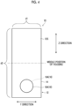
- FIG. 4 is a diagram showing a downstream edge surface of the silencer 10 for a ventilation passage, and an inlet opening portion 16 not appearing on the downstream edge surface is shown in Fig. 4 by a broken line.
- the silencer 10 for a ventilation passage comprises a housing 12 as a main component. Further, a sound absorbing member 30 and a pair of connecting members 40 are disposed in an internal space of the housing 12 as shown in Fig. 1 . Each component of the silencer 10 for a ventilation passage will be described below.
- the housing 12 is a box-shaped hollow body, and includes a wall 14 that surrounds the internal space of the housing 12 as shown in Fig. 1 .
- the housing 12 has a total length in the X direction, has a height in the Y direction, and has a width in the Z direction. Further, the housing 12 of the present embodiment has the shape of a flat rectangular parallelepiped crushed in the Y direction, and includes a plurality of (specifically, six) outer wall surfaces 12S.
- the width (a length in the Z direction) of the housing 12 is larger than the height (a length in the Y direction) of the housing 12.
- a ratio of the length of the longest side of the contour line to the length of the shortest side of the contour line is 1.2 or more.
- the shortest side corresponds to the height of the housing 12, and the length of the shortest side is equal to a length d1 shown in Fig. 4 .
- the longest side corresponds to the width of the housing 12, and the length of the longest side is equal to a length d2 shown in Fig. 4 .
- Each portion of the wall 14 is a plate having a relatively small thickness, and forms both end portions of the housing 12 in the XYZ directions.
- a material of the wall 14 is not particularly limited, but, for example, a metal material, a resin material, a reinforced plastic material, a carbon fiber, and the like can be used as the material of the wall 14.
- metal material examples include aluminum, titanium, magnesium, tungsten, iron, steel, chromium, chromium molybdenum, nichrome-molybdenum, copper, steel galvanized cold commercial (SGCC), and alloys, such as stainless steel.
- natural rubber chloroprene rubber, butyl rubber, ethylene propylene diene rubber (EPDM), silicone rubber, and rubbers including a crosslinking structure thereof can be further used as the material of the wall 14.
- EPDM ethylene propylene diene rubber
- silicone rubber and rubbers including a crosslinking structure thereof can be further used as the material of the wall 14.
- the range in which the inlet opening 16A is present and the range in which the outlet opening 18A is present may be separated (shifted) from each other without overlapping with each other in at least one of the Y direction or the Z direction.
- a portion of the housing 12 forming the vibration portion 20 is one of portions forming the largest outer wall surfaces in the present embodiment, but the present invention is not limited thereto.
- the housing 12 may be provided with a plurality of vibration portions 20 (see Figs. 16 , 19B , and 20B ).
- the vibration portion 20 is adapted to vibrate at a natural frequency thereof.
- the natural frequency of the vibration portion 20 is determined depending on the structure (the dimensions, the shape of an outer edge, and the like) and material of the vibration portion 20, the position of the vibration portion 20 in the housing 12, a method of fixing the vibration portion 20, a method of supporting the vibration portion 20, and the like.
- the natural frequency of the vibration portion 20 can be specified using publicly known natural frequency analysis or natural frequency calculation.
- foaming body and the foaming material include foaming urethane foam, such as CALMFLEX F manufactured by INOAC CORPORATION and urethane foam manufactured by Hikari Co., Ltd., flexible urethane foam, a ceramic particle sintered material, phenol foam, melamine foam, a polyamide foam, and the like.
- a flow resistivity of the sound absorbing material is in a range of 1000 (Pa ⁇ s/m 2 ) to 100000 (Pa ⁇ s/m 2 ). Further, in a case where the structure of the sound absorbing member 30 is a structure in which a plurality of layers are laminated, the flow resistance of the entire structure can be measured and a flow resistivity can be calculated from the thickness of the entire structure.
- each connecting member 40 may comprise a same-diameter portion 40a which is provided at an intermediate portion of the connecting member 40 in a direction of a central axis of the connecting member 40 (X direction) and of which a diameter is constant without being changed as shown in Fig. 6B .
- the external shape of each connecting member 40 is not limited to a cylindrical shape, and may be a prismatic shape.
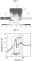
- Figs. 8 and 10 to 15 show graphs showing sound-deadening characteristics of the silencer for a ventilation passage, a horizontal axis represents a frequency (unit: Hz), and a vertical axis represents a transmission loss (unit: dB). Further, Fig. 8 shows a graph in a case of "without sound absorbing material and without vibration", a graph in a case of "without sound absorbing material and with vibration", and a graph in a case of "with sound absorbing material and with vibration”.
- the rear space of the connecting members 40 acts as a type of resonator in the silencer 10 for a ventilation passage, so that sound resonates in the rear space H.
- the rear space H is a space formed between the rear surface, which is close to the connecting members 40, of the inner wall surface of the housing 12 and the connecting members 40, and is reduced in size toward a middle position of the housing 12 in the X direction (see Fig. 1 ). Accordingly, the rear space H (specifically, the rear space H of the upstream connecting member 42) resonates with a principle close to that of the Helmholtz resonator as shown in Fig. 9 . Sound having the resonance frequency can be deadened due to resonance in such a rear space H.
- a rear space 60 is provided in the internal space of the housing 12 on a side opposite to the sound absorbing member 30 in the Z direction. Furthermore, a partition member 62 for partitioning the rear space 60 is disposed in the rear space 60.
- the partition member 62 is a flat plate-like member and partitions the rear space 60 into two spaces in the Z direction. A first space 60a, which is farther from the sound absorbing member 30, of the two spaces has a short length in the Z direction and a small volume as compared to a second space 60b that is closer to the sound absorbing member 30.
- the partition member 62 extends straight in the X direction from an upstream edge surface of the inner wall surface of the housing 12, and a distal end thereof is separated from a downstream edge surface of the inner wall surface of the housing 12. That is, a relatively wide gap is formed between the distal end 62 of the partition member and the inner wall surface (specifically, the downstream edge surface) of the housing 12. This gap corresponds to a communication portion 60c that allows the first space 60a and the second space 60b to communicate with each other.
- portions of the housing 12 adjacent to the rear space 60 in the X and Y directions form vibration portions as shown in Fig. 19B . More specifically, a portion, which is adjacent to the first space 60a, of a portion, which forms the largest outer wall surface, of the wall 14 of the housing 12 forms a first vibration portion 24, and a portion thereof, which is adjacent to the second space 60b, forms a second vibration portion 26.
- Fig. 19B and Fig. 20B to be described later devices provided in the housing 12 are shown by a broken line in order to show a positional relationship between each vibration portion and the devices provided in the housing 12.
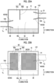
- a silencer 10Y for a ventilation passage shown in Fig. 20A the range in which the inlet opening 16A is present and the range in which the outlet opening 18A is present are separated from each other in the Z direction.
- a rear space 60 of the internal space of the housing 12 positioned on a side opposite to the sound absorbing member 30 in the Z direction is partitioned into two spaces, which are arranged in the X direction, by, for example, a partition member 62 extending in the Z direction.
- the partition member 62 extends straight from an end, which is opposite to the sound absorbing member 30 in the Z direction, of the inner wall surface of the housing 12 toward the sound absorbing member 30, and a distal end thereof is separated from the sound absorbing member 30.
- a first space 60a which is positioned closer to an upstream side, of the two spaces has a short length in the X direction and a small volume as compared to a second space 60b that is positioned closer to a downstream side.
- a communication portion 60c consisting of a relatively wide gap is formed between the distal end 62 of the partition member and the sound absorbing member 30.
- QonPET manufactured by Bridgestone KBG Co.,Ltd.
- the flow resistivity of this sound absorbing member was about 8000 Rayls/m.
- a plate-like portion forming one surface of the housing specifically, the largest outer wall surface (a surface having a size of 130 mm ⁇ 110 mm) was adapted to be capable of vibrating as a vibration portion. Natural vibration calculation was performed for this vibration portion using COMSOL Multiphysics. The fact that the periphery of the plate-like portion as the vibration portion is fixed and restrained was used as a precondition in the calculation. As a result of analysis, it was found that a first natural frequency f1 (resonance frequency) of the vibration portion is 358 Hz.
- Comparative Example 1 the thickness of a wall of the housing was set to 20 mm and vibration in the housing was suppressed. In terms of other points, the configuration of Comparative Example 1 was the same as that of Example 1.
- the first natural frequency f1 of the plate-like portion was 2799 Hz.
- a sound source was disposed on an upstream side of a silencer for a ventilation passage produced in each of Example 1 and Comparative Example 1, sound generated from the sound source was incident on the silencer for a ventilation passage, and the transmittance and reflectivity of sound incident on the silencer for a ventilation passage were measured. Measurement was performed according to a publicly known acoustic tube measurement method (specifically, ASTM E2611) with a microphone 4-terminal method using an acoustic tube having a diameter of 28 mm.
- Example 2 the width (a length in the Z direction) of the housing was set to 90 mm. That is, with regard to the contour line of a cross section of which a normal direction was the X direction among the cross sections of the housing of Example 2, a ratio of the length of the longest side to the length of the shortest side was set to 1.8:1. Further, positions where the inlet opening portion and the outlet opening portion were provided in the housing were shifted from the middle position of the housing in the Z direction by 18 mm. In terms of other points, the configuration of Example 2 was the same as that of Example 1.
- Comparative Example 2 the thickness of the wall of the housing was set to 20 mm and vibration in the housing was suppressed. In terms of other points, the configuration of Comparative Example 2 was the same as that of Example 2.
- Example 3 in the same manner as in Example 1, the transmittance and reflectivity of sound incident on the silencer for a ventilation passage were measured and a transmission loss was measured. Measurement results of the transmission loss are shown in Fig. 12. Fig. 12 also shows the measurement results of Example 2 for comparison.
- Example 3 As seen from Fig. 12 , a peak of a transmission loss appeared near a frequency of 500 Hz as in Example 2. Further, in a case where Example 2 and Example 3 were compared with each other, a transmission loss was larger in Example 2 in a low frequency band of 900 to 1800 and a transmission loss was larger in Example 3 in a band of 1900 Hz or more. This reflected a difference in positions where the inlet opening portion and the outlet opening portion were provided in the housing, and it was found that a sound deadening effect in a low frequency band was improved in a case where each opening portion is shifted from the middle position of the housing (close to an end).
- Example 4 the width (a length in the Z direction) of the housing was set to 60 mm. That is, with regard to the contour line of a cross section of which a normal direction was the X direction among the cross sections of the housing of Example 4, a ratio of the length of the longest side to the length of the shortest side was set to 1.2:1. Further, positions where the inlet opening portion and the outlet opening portion were provided in the housing were set to the middle position of the housing in the Z direction. In terms of other points, the configuration of Example 4 was the same as that of Example 1.
- Comparative Example 3 the thickness of a wall of a housing was set to 20 mm and vibration in the housing was suppressed. In terms of other points, the configuration of Comparative Example 3 was the same as that of Example 4. As result of the above-mentioned natural vibration analysis that was performed for a plate-like portion of the housing of Comparative Example 3 forming the largest outer wall surface (a surface having a size of 60 mm ⁇ 110 mm), the first natural frequency f1 of the plate-like portion was 5834 Hz.
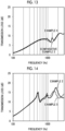
- Example 4 and Comparative Example 3 in the same manner as in Example 1 and Comparative Example 1, the transmittance and reflectivity of sound incident on the silencer for a ventilation passage were measured and a transmission loss was measured. Measurement results of the transmission loss are shown in Fig. 13 .
- Example 4 As seen from Fig. 13 , a peak of a transmission loss appeared at a frequency of about 950 Hz and a transmission loss higher than that of Comparative Example 3 was shown at the peak.
- the specific resonance frequency fr was 1559 Hz and the first natural frequency f1 of the vibration portion was smaller than fr and larger than fr/2. That is, in Example 4, a peak of a transmission loss caused by the natural vibration of the vibration portion occurred in a range of fr/2 or more.
- Example 5 was the same as that of Example 2.
- Example 5 in the same manner as in Example 1, the transmittance and reflectivity of sound incident on the silencer for a ventilation passage were measured and a transmission loss was measured. Measurement results of the transmission loss are shown in Fig. 14. Fig. 14 also shows the measurement results of Example 2 for comparison.
- Example 6 a weight made of an ABS resin was mounted on a central portion of the largest outer wall surface (that is, the vibration portion) of the housing and other points were the same as in Example 2.
- the radius of the weight was set to 20 mm and the height of the weight was set to 10 mm.
- the radius of the weight was set to 20 mm and the height of the weight was set to 20 mm.
- the housing and the weight were collectively formed by a 3D printer.
- Example 9 the thickness of the first vibration portion 24 was set to 2 mm and the thickness of each of the second vibration portion 26, the third vibration portion 28, and the bent part disposed between the second vibration portion 26 and the third vibration portion 28 was set to 20 mm.
- the second vibration portion 26 and the third vibration portion 28 were made to be stiffer than those of Example 8 so that the second vibration portion 26 and the third vibration portion 28 were less likely to oscillate.
- the first natural frequency of the second vibration portion 26 in this case was 6264 Hz
- the first natural frequency of the third vibration portion 28 was 7046 Hz.
- the configuration of Example 9 was the same as that of Example 8.
Landscapes
- Engineering & Computer Science (AREA)
- General Engineering & Computer Science (AREA)
- Chemical & Material Sciences (AREA)
- Combustion & Propulsion (AREA)
- Mechanical Engineering (AREA)
- Physics & Mathematics (AREA)
- Acoustics & Sound (AREA)
- Multimedia (AREA)
- Fluid Mechanics (AREA)
- Aviation & Aerospace Engineering (AREA)
- Duct Arrangements (AREA)
- Pipe Accessories (AREA)
- Soundproofing, Sound Blocking, And Sound Damping (AREA)
Abstract
Description
- The present invention relates to a silencer for a ventilation passage that deadens sound in a ventilation passage.
- Among ventilation passages, there is a ventilation passage that comprises a silencer for deadening sound (noise) passing through the ventilation passage. Examples of such a ventilation passage with a silencer include a duct disclosed in, for example,
JP2016-133226A - The duct disclosed in
JP2016-133226A - Since it is necessary to ensure an installation space for the silencer in a configuration in which the silencer is disposed outside the ventilation passage as with the duct disclosed in
JP2016-133226A - Meanwhile, sound deadening performance against sound having a low frequency band tends to deteriorate in a small silencer. For this reason, it is important for the silencer for a ventilation passage to ensure sound deadening performance against sound having a low frequency band while having a compact structure. In addition, it is preferable that the silencer for a ventilation passage can effectively deaden sound having a high frequency band together with sound having a low frequency band.
- The present invention has been made in consideration of the above-mentioned circumstances, and an object of the present invention is to provide a silencer for a ventilation passage that can solve the problems in the related art, and specifically, can effectively deaden sound having a broad frequency band while having a compact structure.
- In order to achieve the above-mentioned object, the present invention has the following configurations.
- [1] A silencer for a ventilation passage that includes a housing and deadens sound in a ventilation passage, in which an internal space of the housing forms a part of the ventilation passage, and the silencer for a ventilation passage comprising: an inlet opening that is formed in the housing and is positioned on one end side of a part of the ventilation passage; an outlet opening that is formed in the housing and is positioned on the other end side of a part of the ventilation passage; a sound absorbing member that is housed in the housing; and a vibration portion that is provided on the housing and reduces sound passing through the ventilation passage.
- [2] The silencer for a ventilation passage according to [1], in which at least a part of an outer wall surface of the housing is a flat surface, and a portion, of which the outer wall surface is a flat surface, of the housing forms the vibration portion.
- [3] The silencer for a ventilation passage according to [1] or [2], in which the inlet opening is formed in one edge surface of an inner wall surface of the housing in a first direction, the outlet opening is formed in the other edge surface of the inner wall surface of the housing in the first direction, and in a case where a distance between the inlet opening and the outlet opening is denoted by L and a sound speed is denoted by c, a first natural frequency of the vibration portion is less than c/(2 × L).
- [4] The silencer for a ventilation passage according to [3], in which the first natural frequency is less than c/(4 × L).
- [5] The silencer for a ventilation passage according to any one of [1] to [4], in which the housing includes a wall surrounding the internal space of the housing, and the wall includes the vibration portion and each portion of the wall is made of the same material.
- [6] The silencer for a ventilation passage according to [5], in which the vibration portion and a peripheral portion of the vibration portion are continuous with each other in the wall.
- [7] The silencer for a ventilation passage according to any one of [1] to [6], in which the inlet opening is formed in one edge surface of an inner wall surface of the housing in a first direction, the outlet opening is formed in the other edge surface of the inner wall surface of the housing in the first direction, and with regard to a contour line of a cross section of which a normal direction is the first direction among cross sections of the housing, a ratio of a length of a longest side of the contour line to a length of a shortest side of the contour line is 1.2 or more.
- [8] The silencer for a ventilation passage according to any one of [1] to [7], in which the inlet opening is formed in one edge surface of an inner wall surface of the housing in a first direction, the outlet opening is formed in the other edge surface of the inner wall surface of the housing in the first direction, and a range in which the inlet opening is present and a range in which the outlet opening is present overlap with each other in a second direction intersecting with the first direction and in a third direction intersecting with both the first direction and the second direction.
- [9] The silencer for a ventilation passage according to any one of [1] to [8], in which the inlet opening is formed in one edge surface of an inner wall surface of the housing in a first direction, the outlet opening is formed in the other edge surface of the inner wall surface of the housing in the first direction, a length of the housing in a second direction intersecting with the first direction is longer than a length of the housing in a third direction intersecting with both the first direction and the second direction, and each of the inlet opening and the outlet opening is provided at a position closer to an end of the housing than to a middle of the housing in the second direction.
- [10] The silencer for a ventilation passage according to any one of [1] to [9], in which the inlet opening is formed in one edge surface of an inner wall surface of the housing in a first direction, the outlet opening is formed in the other edge surface of the inner wall surface of the housing in the first direction, a connecting member is connected to at least one opening of the inlet opening or the outlet opening in the internal space of the housing, a connecting member-side opening portion connected to the at least one opening is provided on an inner side of the connecting member, and a size of the connecting member-side opening portion is increased as a distance from the at least one opening in the first direction is increased.
- [11] The silencer for a ventilation passage according to [10], in which the connecting member is connected to each of the inlet opening and the outlet opening in the internal space of the housing.
- [12] The silencer for a ventilation passage according to any one of [1] to [11], in which a weight is mounted on the vibration portion.
- [13] The silencer for a ventilation passage according to any one of [1] to [12], in which the inlet opening is formed in one edge surface of an inner wall surface of the housing in a first direction, the outlet opening is formed in the other edge surface of the inner wall surface of the housing in the first direction, and the sound absorbing member is disposed to avoid a range in which the inlet opening is present and a range in which the outlet opening is present in a second direction intersecting with the first direction and in a third direction intersecting with both the first direction and the second direction.
- [14] The silencer for a ventilation passage according to [13], in which a ratio of a region, which is occupied by the sound absorbing member, to a volume of a space, which excludes a flow channel portion in the housing, of the internal space of the housing is 80% or more.
- [15] The silencer for a ventilation passage according to any one of [1] to [14], in which openings formed in the housing are only the inlet opening and the outlet opening.
- [16] The silencer for a ventilation passage according to [3] or [4], in which the vibration portion is capable of deadening sound having a frequency of 2400 Hz or less by vibrating at the first natural frequency.
- [17] The silencer for a ventilation passage according to [3] or [4], in which the vibration portion is capable of deadening sound having a frequency of 1700 Hz or less by vibrating at the first natural frequency.
- [18] The silencer for a ventilation passage according to any one of [1] to [17], in which the housing is provided with a plurality of the vibration portions.
- [19] The silencer for a ventilation passage according to any one of [1] to [18], in which a part of the internal space of the housing forms a resonance space that absorbs sound via resonance.
- The silencer for a ventilation passage according to an embodiment of the present invention deadens sound having a low frequency band via the vibration of the housing that forms a part of the ventilation passage. Further, sound having a high frequency band can be deadened by the sound absorbing member disposed in the housing. As a result, it is possible to provide a silencer for a ventilation passage that can deaden sound over a high frequency band from a low frequency band by a relative compact structure.
-
-
Fig. 1 is a cross-sectional view showing the configuration of a silencer for a ventilation passage according to an embodiment of the present invention. -
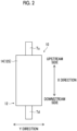
Fig. 2 is a top view showing the silencer for a ventilation passage according to the embodiment of the present invention. -
Fig. 3 is a side view showing the silencer for a ventilation passage according to the embodiment of the present invention. -
Fig. 4 is a diagram showing a downstream edge surface of the silencer for a ventilation passage according to the embodiment of the present invention. -
Fig. 5 is a side view of a silencer for a ventilation passage according to a first modification example of the present invention. -
Fig. 6A is a side view showing a first modification example of a connecting member. -
Fig. 6B is a side view showing a second modification example of the connecting member. -
Fig. 7 is a diagram showing a sound energy distribution and a flow of sound in a housing in a case where λ/4 resonance occurs. -
Fig. 8 is a graph showing sound-deadening characteristics of the silencer for a ventilation passage. -
Fig. 9 is a diagram showing a sound pressure distribution in the housing in a case where resonance in a rear space of the connecting members occurs. -
Fig. 10 is a graph showing sound-deadening characteristics measured in Example 1 and Comparative Example 1, respectively. -
Fig. 11 is a graph showing sound-deadening characteristics measured in Example 2 and Comparative Example 2, respectively. -
Fig. 12 is a graph showing sound-deadening characteristics measured in Examples 2 and 3, respectively. -
Fig. 13 is a graph showing sound-deadening characteristics measured in Example 4 and Comparative Example 3, respectively. -
Fig. 14 is a graph showing sound-deadening characteristics measured in Examples 2 and 5, respectively. -
Fig. 15 is a graph showing sound-deadening characteristics measured in Examples 6 and 7, respectively. -
Fig. 16 is a diagram showing an appearance of a silencer according to Examples 8 and 9. -
Fig. 17 is a graph showing sound-deadening characteristics measured in Examples 8 and 9. -
Fig. 18 is a diagram showing a relationship between an occupancy ratio of a sound absorbing member and the sound pressure of wind noise. -
Fig. 19A is a side view of a silencer for a ventilation passage according to a second modification example of the present invention. -
Fig. 19B is a cross-sectional view of the silencer for a ventilation passage according to the second modification example of the present invention, and is a view corresponding toFig. 1 . -
Fig. 20A is a side view of a silencer for a ventilation passage according to a third modification example of the present invention. -
Fig. 20B is a cross-sectional view of the silencer for a ventilation passage according to the third modification example of the present invention, and is a view corresponding toFig. 1 . - A silencer for a ventilation passage according to an embodiment of the present invention will be described in detail below with reference to a preferred embodiment shown in the accompanying drawings. An embodiment described below is merely an example for facilitating the understanding of the present invention, and does not limit the present invention. That is, the present invention may be modified or improved from the following embodiment without departing from the scope thereof. Further, the material, the shape, or the like of each member used to implement the present invention can be set in any manner in accordance with the purpose of use of the present invention and the technical level and the like at the time of implementation of the present invention. Furthermore, the present invention includes its equivalents.
- In addition, in this specification, a numerical range represented using "to" means a range that includes numerical values written before and after "to" as a lower limit and an upper limit.
- Further, in this specification, "orthogonal", "perpendicular", and "parallel" include a range of an error to be allowed in a technical field to which the present invention pertains. For example, "orthogonal", "perpendicular", and "parallel" in this specification mean that an angle is in a range including an error smaller than ±10° from exact orthogonal, exact perpendicular, or exact parallel. An error from exact orthogonal or exact parallel is preferably 5° or less and more preferably 3° or less.
- Furthermore, in this specification, the meanings of "the same", "identical", and "equal" may include the range of an error to be generally allowed in the technical field to which the present invention pertains.
- In addition, in this specification, the meanings of "the entire", "any", and "all" may include the range of an error to be generally allowed in the technical field to which the present invention pertains, and may include the case of, for example, 99% or more, 95% or more, or 90% or more in addition to the case of 100%.
- Further, "sound deadening" in the present invention is a concept including both of sound insulation and sound absorption. The sound insulation means blocking sound, in other words, preventing the transmission of sound. The sound absorption means reducing reflected sound and means absorbing sound (audio) in easy terms.
- Furthermore, three directions orthogonal to each other will be referred to as "XYZ directions" in the following description. The X direction corresponds to a first direction of the present invention, the Z direction corresponds to a second direction of the present invention, and the Y direction corresponds to a third direction of the present invention.
- In addition, in the following description, a side of a ventilation passage closer to an air outlet will be referred to as "downstream side" and a side opposite thereto, that is, a side of the ventilation passage closer to an air inlet will be referred to as "upstream side".
- A configuration of a
silencer 10 for a ventilation passage according to an embodiment of the present invention (hereinafter, referred to as the present embodiment) will be described with reference toFigs. 1 to 6B .Fig. 4 is a diagram showing a downstream edge surface of thesilencer 10 for a ventilation passage, and aninlet opening portion 16 not appearing on the downstream edge surface is shown inFig. 4 by a broken line. - The
silencer 10 for a ventilation passage is disposed at an intermediate position on a ventilation passage provided in, for example, a device or a building. That is, thesilencer 10 for a ventilation passage is installed in a state where thesilencer 10 for a ventilation passage is interposed between an upstream ventilation passage Tu positioned on an upstream side of thesilencer 10 for a ventilation passage and a downstream ventilation passage Td positioned on a downstream side of thesilencer 10 for a ventilation passage as shown inFig. 1 . Each of the upstream ventilation passage Tu and the downstream ventilation passage Td is formed of a hose, a pipe, or the like. - As shown in
Figs. 1 to 4 , thesilencer 10 for a ventilation passage comprises ahousing 12 as a main component. Further, asound absorbing member 30 and a pair of connectingmembers 40 are disposed in an internal space of thehousing 12 as shown inFig. 1 . Each component of thesilencer 10 for a ventilation passage will be described below. - The
housing 12 is a box-shaped hollow body, and includes awall 14 that surrounds the internal space of thehousing 12 as shown inFig. 1 . Thehousing 12 has a total length in the X direction, has a height in the Y direction, and has a width in the Z direction. Further, thehousing 12 of the present embodiment has the shape of a flat rectangular parallelepiped crushed in the Y direction, and includes a plurality of (specifically, six) outer wall surfaces 12S. - The shape of the
housing 12 will be described. The width (a length in the Z direction) of thehousing 12 is larger than the height (a length in the Y direction) of thehousing 12. Specifically, with regard to the contour line of a cross section of which a normal direction is the X direction among cross sections of thehousing 12, a ratio of the length of the longest side of the contour line to the length of the shortest side of the contour line is 1.2 or more. Here, the shortest side corresponds to the height of thehousing 12, and the length of the shortest side is equal to a length d1 shown inFig. 4 . The longest side corresponds to the width of thehousing 12, and the length of the longest side is equal to a length d2 shown inFig. 4 . - Each portion of the
wall 14 is a plate having a relatively small thickness, and forms both end portions of thehousing 12 in the XYZ directions. A material of thewall 14 is not particularly limited, but, for example, a metal material, a resin material, a reinforced plastic material, a carbon fiber, and the like can be used as the material of thewall 14. - Examples of the metal material include aluminum, titanium, magnesium, tungsten, iron, steel, chromium, chromium molybdenum, nichrome-molybdenum, copper, steel galvanized cold commercial (SGCC), and alloys, such as stainless steel.
- Examples of the resin material include an acrylic resin, polymethyl methacrylate, polycarbonate, polyamideide, polyalylate, polyetherimide, polyacetal, polyetheretherketone, polyphenylene sulfide, polysulfone, polyethylene terephthalate, polybutylene terephthalate, polyimide, an ABS resin (a copolymer synthetic resin of acrylonitrile, a flame-retardant ABS resin, butadiene, and styrene), polypropylene, triacetylcellulose (TAC), polypropylene (PP), polyethylene (PE), polystyrene (PS), an acrylate styrene acrylonitrile (ASA) resin, a polyvinyl chloride (PVC) resin, and a polylactic acid (PLA) resin.
- Examples of the reinforced plastic material include carbon fiber reinforced plastics (CFRP) and glass fiber reinforced plastics (GFRP).
- Further, natural rubber, chloroprene rubber, butyl rubber, ethylene propylene diene rubber (EPDM), silicone rubber, and rubbers including a crosslinking structure thereof can be further used as the material of the
wall 14. - For example, a plurality of (specifically, six) plates are disposed in a box shape and the plates adjacent to each other are joined to each other, so that the
wall 14 is formed. Alternatively, in a case where thewall 14 is divided into two fragments to be fragmented, each fragment may be formed using injection molding or the like and the fragments may be combined with each other to form thewall 14. Further, each portion of thewall 14 forms a flat plate, and two portions of thewall 14 disposed at positions facing each other are arranged in parallel. Furthermore, theouter wall surfaces 12S (XZ planes), which are positioned at both ends of thehousing 12 in the Y direction, among the outer wall surfaces 12S of thehousing 12 formed of the outer surfaces of thewall 14 are surfaces having the largest area among the outer wall surfaces 12S, and will be referred to as largest outer wall surfaces in the following description. The outer wall surfaces 12S of thehousing 12 include one or more portions that form a plane (more specifically, a flat surface), including the largest outer wall surfaces. - Furthermore, each portion of the
wall 14 is made of the same material in the present embodiment. However, the present invention is not limited thereto, and a part of the wall 14 (for example, avibration portion 20 to be described later) may be made of a material different from the material of a peripheral portion thereof. Alternatively, a part of thewall 14, for example, thevibration portion 20 may be made of the same material as the peripheral portion thereof, but may have a thickness different from the thickness of the peripheral portion thereof. - An
inlet opening portion 16 is provided at one end portion of thewall 14 in the X direction, and anoutlet opening portion 18 is provided at the other end portion thereof. That is, the internal space of thehousing 12 forms a part of the ventilation passage, and air (wind) flowing into thehousing 12 through theinlet opening portion 16 flows out of thehousing 12 through theoutlet opening portion 18. In this respect, the X direction corresponds to a direction in which air flows in thehousing 12, that is, a ventilation direction. - The
inlet opening portion 16 and theoutlet opening portion 18 are holes penetrating thewall 14 in the X direction, and communicate with the internal space of thehousing 12. Further, as shown inFig. 1 , the upstream ventilation passage Tu is connected to theinlet opening portion 16 and the downstream ventilation passage Td is connected to theoutlet opening portion 18. Each of theinlet opening portion 16 and theoutlet opening portion 18 may penetrate thewall 14 in parallel to the X direction or may penetrate thewall 14 to be inclined with respect to the X direction. - Here, a boundary position between the
inlet opening portion 16 and the internal space of thehousing 12, that is, an inner opening end of theinlet opening portion 16 corresponds to aninlet opening 16A. As shown inFig. 1 , theinlet opening 16A is formed in an upstream edge surface (in other words, one edge surface in the X direction) of an inner wall surface of thehousing 12. In other words, theinlet opening 16A is positioned on an upstream side (one end side) of a part of the ventilation passage that is formed by the internal space of thehousing 12. Further, a boundary position between theoutlet opening portion 18 and the internal space of thehousing 12, that is, an inner opening end of theoutlet opening portion 18 corresponds to anoutlet opening 18A. As shown inFig. 1 , theoutlet opening 18A is formed in a downstream edge surface (in other words, the other edge surface in the X direction) of the inner wall surface of thehousing 12. In other words, theoutlet opening 18A is positioned on a downstream (the other end side) of a part of the ventilation passage that is formed by the internal space of thehousing 12. - In the present embodiment, openings formed in the
housing 12, more specifically, in the inner wall surface of thehousing 12 are only theinlet opening 16A and theoutlet opening 18A. - The shape (contour shape) of each of the
inlet opening 16A and theoutlet opening 18A is not particularly limited, but may be, for example, a circular shape, an elliptical shape, a polygonal shape, such as a triangular shape or a quadrangular shape, or an indefinite shape. Further, the size of each of theinlet opening 16A and theoutlet opening 18A may be the same or different. - Furthermore, as shown in
Figs. 1 and4 , each of theinlet opening portion 16 including theinlet opening 16A and theoutlet opening portion 18 including theoutlet opening 18A is provided at a position closer to an end of thehousing 12 than to the middle of thehousing 12 in the Z direction. That is, theinlet opening portion 16 and theoutlet opening portion 18 are provided not in the middle portion of thehousing 12 but at positions close to an end of thehousing 12 in a longitudinal direction of thehousing 12. - A surface (edge surface), which is farthest from the
inlet opening portion 16 and theoutlet opening portion 18 in the Z direction, of the inner wall surface of thehousing 12 will be referred to as "top surface" in the following description. Further, a surface (edge surface), which is opposite to the top surface in the Z direction, of the inner wall surface of thehousing 12 will be referred to as "rear surface". - Furthermore, in the present embodiment, as seen from
Figs. 1 to 4 , a range in which theinlet opening 16A is present and a range in which theoutlet opening 18A is present in the Y direction and the Z direction overlap with each other. Here, a range in which each opening is present in the Y direction and the Z direction is a range in which each opening is present on an imaginary plane (YZ plane) of which a normal direction is the X direction in a case where each opening is projected on the imaginary plane. Since the range in which theinlet opening 16A is present and the range in which theoutlet opening 18A is present overlap with each other in this way, ventilation performance is improved and air (wind) smoothly flows from the inlet opening 16A toward theoutlet opening 18A. - From the viewpoint of improving ventilation performance, it is preferable that the range in which the
inlet opening 16A is present and the range in which theoutlet opening 18A is present completely coincide with each other in a case where theinlet opening 16A and the outlet opening 18A have the same size. Further, in a case where theinlet opening 16A and the outlet opening 18A have different sizes, it is preferable that a range in which a smaller opening is present is within a range in which a larger opening is present as shown inFig. 4 . However, the present invention is not limited thereto, and the range in which theinlet opening 16A is present and the range in which theoutlet opening 18A is present may partially overlap with each other. Furthermore, due to restrictions on the design of the ventilation passage, or the like, the range in which theinlet opening 16A is present and the range in which theoutlet opening 18A is present may be separated (shifted) from each other without overlapping with each other in at least one of the Y direction or the Z direction. - In addition, in the present embodiment, the
housing 12 is provided with avibration portion 20 that is adapted to vibrate in response to sound entering thehousing 12. Thevibration portion 20 is formed of a part of thewall 14, specifically, a portion of which an outer wall surface is a flat surface. In the present embodiment, a portion forming the largest outer wall surface forms thevibration portion 20. However, a portion of thehousing 12 forming thevibration portion 20 may be a portion forming theouter wall surface 12S other than the largest outer wall surface. - In the
wall 14, thevibration portion 20 is continuous with a peripheral portion of thevibration portion 20. The fact that thevibration portion 20 is continuous with the peripheral portion means that thevibration portion 20 and the peripheral portion are integrated with each other. A boundary between thevibration portion 20 and the peripheral portion may be provided with a seam or may have a seamless structure without a seam. However, in a case where there is no seam between thevibration portion 20 and the peripheral portion, higher strength and higher durability can be obtained in thehousing 12 as compared to a case where there is a seam (that is, a welded portion or an adhesion portion). - From the viewpoint that the
vibration portion 20 easily vibrates to increase an effect caused by natural vibration, a structure in which the peripheral portion of thevibration portion 20 can be regarded as a fixed end is preferable. Here, since corners (bent portions) of thehousing 12 are regarded as portion not vibrating as fixed ends, a structure in which the entire surface surrounded by corners in thewall 14 of thehousing 12 functions as thevibration portion 20 is desirable. - Further, the
vibration portion 20 may have a thickness smaller than a thickness of the peripheral portion to be capable of easily vibrating. Specifically, it is preferable that the thickness of thevibration portion 20 is set to 0.01 × t to 0.46 × t in a case where the thickness of the peripheral portion is denoted by t. In a case where thevibration portion 20 is excessively thinner than the peripheral portion, the structural strength of thehousing 12 is excessively low. For this reason, it is desirable that the thickness of thevibration portion 20 is set to about 1/100 even if the thickness of thevibration portion 20 is reduced. - Furthermore, in a case where the material of a plate is the same (exactly, young's modulus is the same), the stiffness of the plate is changed in proportion to the cube of a thickness. For this reason, in a case where the thickness of the
vibration portion 20 is set to 0.46 or less times the thickness of the peripheral portion, the stiffness of the peripheral portion can be increased to about 10 times the stiffness of thevibration portion 20. As a result, natural vibration can be easily obtained. - In addition, the
vibration portion 20 may be a portion forming at least oneouter wall surface 12S of the six outer wall surfaces 12S of thehousing 12, or thevibration portion 20 may be provided over two or more surfaces. - Further, the
vibration portion 20 consists of a flat plate in the present embodiment, but the present invention is not limited thereto. Thevibration portion 20 may be formed of a plate that is curved in an arch shape. However, since thecurved vibration portion 20 is less likely to vibrate, thevibration portion 20 having a flat shape is more preferable. - Furthermore, a portion of the
housing 12 forming thevibration portion 20 is one of portions forming the largest outer wall surfaces in the present embodiment, but the present invention is not limited thereto. Thehousing 12 may be provided with a plurality of vibration portions 20 (seeFigs. 16 ,19B , and20B ). - The
vibration portion 20 is adapted to vibrate at a natural frequency thereof. The natural frequency of thevibration portion 20 is determined depending on the structure (the dimensions, the shape of an outer edge, and the like) and material of thevibration portion 20, the position of thevibration portion 20 in thehousing 12, a method of fixing thevibration portion 20, a method of supporting thevibration portion 20, and the like. The natural frequency of thevibration portion 20 can be specified using publicly known natural frequency analysis or natural frequency calculation. - For example, vibration is applied using an impulse hammer, such as "GK-3100" manufactured by Ono Sokki Co., Ltd., and vibration is measured with an acceleration detector and is converted into a frequency using a fast fourier transform (FFT) analyzer, so that an actually measured value of a natural frequency can be obtained as a frequency response. In a case where a measurement is made at a plurality of points at this time, a vibration mode can also be analyzed using actual measurement. Further, a tester provided as a set, such as "natural frequency measurement system CAT-SA02 NF" manufactured by RION Co., Ltd., may be used. Many JIS standards for a procedure for actually measuring a natural frequency are also determined for each industry, and a natural frequency can be obtained according to, for example, JISG0602, JISB0908, and JISC60068-2-81, and the like.
- Natural frequency calculation can be performed using general structural dynamics simulation. Specifically, in a case where the size of a material, physical properties (young's modulus, density, Poisson's ratio, and the like) of a material, and surrounding constraint conditions are input to various types of commercial software, such as COMSOL, ANSYS, and Abaqus, or self-made software, a natural frequency can be calculated.
- Further, in a case where the lowest-order first natural frequency among natural frequencies of the
vibration portion 20 is denoted by f1 (unit: Hz) in the present embodiment, the first natural frequency f1 satisfies the following expression (1).
- In Expression (1), c denotes a sound speed (unit: m/s). Further, L denotes a distance (unit: m) between the
inlet opening 16A and theoutlet opening 18A, specifically, a distance between the position of a geometric center of theinlet opening 16A and a position of a geometric center of theoutlet opening 18A. In a case where each opening has the shape of a circle, the position of the geometric center of each opening is the position of the center of the circle. The distance L is a distance between the openings, in other words, a length of a path along which an air stream flows in thehousing 12. - The inventor of the present invention has found that sound having a low frequency band can be efficiently deadened using the vibration of the
vibration portion 20 in a case where Expression (1) is satisfied. Here, a right side of Expression (1), that is, a frequency corresponding to c/(2 × L) is a frequency of sound of which a half of a wavelength λ (unit: m), that is, λ/2 corresponds to the distance L. Further, a frequency corresponding to c/(2 × L) corresponds to a frequency of resonance in thehousing 12 in the X direction (ventilation direction), and will also be referred to as a specific resonance frequency fr in the following description. - Furthermore, in a case where the first natural frequency f1 of the
vibration portion 20 satisfies the following expression (2), sound having a frequency lower than a frequency of sound of which a quarter of a wavelength λ (unit: m), that is, λ/4 corresponds to the distance L can be efficiently deadened.
- A frequency band of which sound can be deadened in a case where the
vibration portion 20 vibrates at the first natural frequency f1 satisfying Expression (1) or (2) is 2400 Hz or less, specifically, 1700 Hz or less (seeFig. 8 ). - As shown in
Fig. 5 , aweight 22 may be mounted on the surface of thevibration portion 20 to adjust the first natural frequency f1 of thevibration portion 20. In a case where such aweight 22 is mounted, the first natural frequency f1 can be further lowered. Theweight 22 may be made of the same material as the material of thevibration portion 20, that is, thewall 14, or may be made of a different from the material of thewall 14. Further, the size of theweight 22, the number ofweights 22, and a position at which theweight 22 is mounted on thevibration portion 20 are not particularly limited. Furthermore, for example, a fixing protrusion (specifically, a screwing protrusion, or the like), a convex screwing structure, and the like mounted on thehousing 12 can also be used as theweight 22. - The
sound absorbing member 30 is housed in thehousing 12 as shown inFig. 1 , and absorbs high-frequency sound entering thehousing 12. A sound absorbing material that converts sound energy into thermal energy to absorb sound can be used as thesound absorbing member 30 as appropriate. Examples of the sound absorbing material include a porous sound absorbing material, specifically, a foaming body, a foaming material, and a nonwoven fabric-based sound absorbing material. Specific examples of the foaming body and the foaming material include foaming urethane foam, such as CALMFLEX F manufactured by INOAC CORPORATION and urethane foam manufactured by Hikari Co., Ltd., flexible urethane foam, a ceramic particle sintered material, phenol foam, melamine foam, a polyamide foam, and the like. Specific examples of the nonwoven fabric-based sound absorbing material include a microfiber nonwoven fabric such as Thinsulate manufactured by 3M Company, and a polyester nonwoven fabric (including a two-layer fabric that includes a high-density thin nonwoven fabric provided on a surface side and a low-density nonwoven fabric provided on a back side) such as White Kyuon manufactured by TOKYO Bouon and QonPET manufactured by Bridgestone KBG Co.,Ltd., a plastic nonwoven fabric such as an acrylic fiber nonwoven fabric, a natural fiber nonwoven fabric such as wool and felt, a metal nonwoven fabric, a glass nonwoven fabric, and the like. - In addition to the examples described above, various sound absorbing materials, such as a sound absorbing material consisting of a material including a minute amount of air (specifically, a sound absorbing material consisting of glass wool, rock wool, and nanofiber-based fiber), can be used as the sound absorbing material as the
sound absorbing member 30. Examples of the nanofiber-based fiber include silica nano fiber and acrylic nanofiber, such as XAI manufactured by Mitsubishi Chemical Corporation. - Moreover, a sound absorbing body that consists of a plate or a film in which innumerable through-holes having a diameter of about 100 µm are formed, such as a micro perforated plate, can be used as the
sound absorbing member 30. In this case, sound can be absorbed by the sound absorbing body and a rear space formed on the rear side of the sound absorbing body. Examples of the micro perforated plate include a micro perforated plate made of aluminum, such as SUONO manufactured by DAIKEN CORPORATION, a micro perforated plate made of a vinyl chloride resin, such as DI-NOC manufactured by 3M Company, and the like. Further, another sound absorbing material may be disposed in the rear space, and a plurality ofsound absorbing members 30 may be used in combination. - The
sound absorbing member 30 can be considered in other cases. For example, thesound absorbing member 30 may be formed of a plate-like body or a film-like body that resonates in a case where sound having a frequency close to a resonance frequency is incident thereon, and may convert sound energy into thermal energy via the internal loss of the plate or the film to absorb sound. Further, thesound absorbing member 30 may be a resonator-type sound absorbing structure consisting of a perforated plate. In a case where sound having the same frequency as a resonance frequency collides with thesound absorbing member 30, air corresponding to hole portions may vibrate and thesound absorbing member 30 may convert sound energy into thermal energy via a viscosity loss at that time. Furthermore, the sound absorbing structure and another sound absorbing material may be disposed and a plurality ofsound absorbing members 30 may be used in combination. - For the reason that ventilation performance in the
housing 12 is to be ensured in thehousing 12, thesound absorbing member 30 is disposed to avoid the range in which theinlet opening 16A is present and the range in which theoutlet opening 18A is present in the Y direction and the Z direction. Simply, thesound absorbing member 30 is disposed at a position outside the range in which theinlet opening 16A is present and is disposed at a position outside the range in which theoutlet opening 18A is present in the Y direction and the Z direction. Further, thesound absorbing member 30 may have a tubular shape. In that case, a space positioned in thesound absorbing member 30, that is, the inside of the tube may form a part of the ventilation passage. - Furthermore, in order to ensure ventilation performance in the
housing 12 while maintaining sound absorption performance in a high frequency band, an occupancy ratio of thesound absorbing member 30 is preferably 80% or more, more preferably 90% or more, and particularly preferably 95%. The occupancy ratio of thesound absorbing member 30 is a ratio (volume ratio) of a region, which is occupied by thesound absorbing member 30, to the volume of a space, which excludes a flow channel portion 50 (seeFig. 1 ) in thehousing 12, of the internal space of thehousing 12. Here, theflow channel portion 50 is a space, which forms a part of the ventilation passage, of the internal space of thehousing 12 and is a space that is connected from the inlet opening 16A to theoutlet opening 18A on a straight pipe in the X direction. Further, it is preferable that theflow channel portion 50 is open (is not blocked by the sound absorbing member or the like) in thehousing 12. However, as long as the ventilation passage is not blocked even in a configuration in which thesound absorbing member 30 is disposed in the middle of theflow channel portion 50, thesilencer 10 for a ventilation passage can be used as the silencer for a ventilation passage according to the embodiment of the present invention. - In addition, in a case where a sound absorbing material is used as the
sound absorbing member 30, it is preferable that a flow resistivity of the sound absorbing material is in a range of 1000 (Pa×s/m2) to 100000 (Pa×s/m2). Further, in a case where the structure of thesound absorbing member 30 is a structure in which a plurality of layers are laminated, the flow resistance of the entire structure can be measured and a flow resistivity can be calculated from the thickness of the entire structure. - The pair of connecting
members 40 is disposed in the internal space of thehousing 12 as shown inFig. 1 , one connecting member 40 (hereinafter, referred to as an upstream connecting member 42) is connected to theinlet opening 16A, and the other connecting member (hereinafter, referred to as a downstream connecting member 44) is connected to theoutlet opening 18A. - Each of the upstream connecting
member 42 and the downstream connectingmember 44 is a cylindrical member, and specifically has the shape of a truncated cone (that is, a tapered shape) of which an outer diameter and an inner diameter are gradually changed like a horn. - The
upstream connecting member 42 is mounted on the inner wall surface of thehousing 12 in a state where an end, which has a smaller diameter, of the upstream connectingmember 42 faces theinlet opening 16A. Likewise, the downstream connectingmember 44 is mounted on the inner wall surface of thehousing 12 in a state where an end, which has a smaller diameter, of the downstream connectingmember 44 faces theoutlet opening 18A. In other words, the area of a cross section (specifically, an area surrounded by the outer edge of the cross section) of each connectingmember 40 of which a normal direction is the X direction is increased as a distance from the opening to which each connectingmember 40 is connected in the X direction is increased. - A connecting member-
side opening portion 46 connected to theinlet opening 16A is provided on an inner side of the upstream connectingmember 40 as shown inFig. 1 . The size of the connecting member-side opening portion 46 is increased as a distance from theinlet opening 16A in the X direction is increased. Further, a connecting member-side opening portion 48 connected to theoutlet opening 18A is provided on an inner side of the downstream connectingmember 40. The size of the connecting member-side opening portion 48 is increased as a distance from theoutlet opening 18A in the X direction is increased. - It is preferable that an opening of the upstream connecting
member 42 facing the inlet opening 16A has the same shape as theinlet opening 16A and has substantially the same opening area as theinlet opening 16A. It is preferable that an opening of the downstream connectingmember 44 facing the outlet opening 18A has the same shape as theoutlet opening 18A and has substantially the same opening area as theoutlet opening 18A. - Each connecting
member 40 may be made of the same material as thewall 14 of thehousing 12, or may be made of the same material as the upstream ventilation passage Tu and the downstream ventilation passage Td. Further, a method of mounting each connectingmember 40 is not particularly limited. For example, an edge surface of each connectingmember 40 may be joined to the inner wall surface of thehousing 12 and fixed by an adhesive or fasteners, such as screws. Alternatively, each connectingmember 40 may be connected to the upstream ventilation passage Tu or the downstream ventilation passage Td. - The shape of each connecting
member 40 may be a shape in which a peripheral wall is curved in a convex shape toward a central axis of the connectingmember 40 as shown inFig. 6A . - Further, each connecting
member 40 may comprise a same-diameter portion 40a which is provided at an intermediate portion of the connectingmember 40 in a direction of a central axis of the connecting member 40 (X direction) and of which a diameter is constant without being changed as shown inFig. 6B . Furthermore, the external shape of each connectingmember 40 is not limited to a cylindrical shape, and may be a prismatic shape. - Moreover, the connecting
members 40 are connected to both theinlet opening 16A and theoutlet opening 18A in the present embodiment, but the present invention is not limited thereto. The connectingmember 40 may be connected to only any one of theinlet opening 16A or theoutlet opening 18A. Further, both theinlet opening 16A and theoutlet opening 18A may not be provided with the connectingmembers 40. - The
silencer 10 for a ventilation passage deadens sound in the ventilation passage via the vibration of thevibration portion 20, acoustic resonance in thehousing 12, resonance in the rear space of the connectingmembers 40, and the absorption of sound caused by thesound absorbing member 30. - Specifically, in a case where (2n + 1) × λ/4 (n is a natural number) coincides with a distance between the inner wall surface of the
housing 12 and the opening (specifically, theinlet opening 16A or theoutlet opening 18A) in thesilencer 10 for a ventilation passage, acoustic resonance occurs in thehousing 12 at a frequency of the wavelength λ. For convenience, this resonance will be referred to as "λ/4 resonance". The λ/4 resonance is, for example, resonance in the Z direction inFig. 4 .Fig. 7 shows calculation results of a finite element method for an acoustic intensity vector and a sound energy distribution in thehousing 12 in a case where λ/4 resonance occurs. As seen fromFig. 7 , sound energy is satisfactorily transmitted not in the flow channel portion (ventilation passage) but in a direction spreading inside thehousing 12 at the time of λ/4 resonance, so that sound can be deadened in thehousing 12. - In the present embodiment, the
inlet opening portion 16 and theoutlet opening portion 18 are present at positions close to an end of thehousing 12 in the longitudinal direction of the housing 12 (the Z direction) and are farther from the top surface of the inner wall surface of thehousing 12. Since theinlet opening portion 16 and theoutlet opening portion 18 are away from the top surface as described above, a resonance frequency in λ/4 resonance can be lowered. - Further, in the
silencer 10 for a ventilation passage, thevibration portion 20 vibrates at the first natural frequency f1 satisfying Expression (1) described above. Accordingly, sound having a frequency lower than the frequency of sound of which λ/4 corresponds to the distance L is emitted to the outside of thehousing 12 due to resonance. As a result, low-frequency sound can be deadened as shown inFig. 8. Figs. 8 and10 to 15 show graphs showing sound-deadening characteristics of the silencer for a ventilation passage, a horizontal axis represents a frequency (unit: Hz), and a vertical axis represents a transmission loss (unit: dB). Further,Fig. 8 shows a graph in a case of "without sound absorbing material and without vibration", a graph in a case of "without sound absorbing material and with vibration", and a graph in a case of "with sound absorbing material and with vibration". - Furthermore, the rear space of the connecting members 40 (specifically, the upstream connecting member 42) acts as a type of resonator in the
silencer 10 for a ventilation passage, so that sound resonates in the rear space H. The rear space H is a space formed between the rear surface, which is close to the connectingmembers 40, of the inner wall surface of thehousing 12 and the connectingmembers 40, and is reduced in size toward a middle position of thehousing 12 in the X direction (seeFig. 1 ). Accordingly, the rear space H (specifically, the rear space H of the upstream connecting member 42) resonates with a principle close to that of the Helmholtz resonator as shown inFig. 9 . Sound having the resonance frequency can be deadened due to resonance in such a rear space H. - Moreover, in the
silencer 10 for a ventilation passage, sound is absorbed by thesound absorbing member 30 provided in thehousing 12. Accordingly, as shown inFig. 8 , sound can be effectively deadened (absorbed) at a frequency higher than the frequency of sound of which λ/2 corresponds to the distance L. As seen fromFig. 8 , the effect of thesound absorbing member 30 is reduced at a frequency lower than the frequency of sound of which λ/4 corresponds to the distance L. - Meanwhile, as the
general silencer 10 for a ventilation passage is reduced in size, it is difficult for thegeneral silencer 10 for a ventilation passage to deaden sound having a low frequency band. On the other hand, in a case where the distance L is lengthened, the frequency band of sound to be deadened can be lowered. However, in a case where the distance L is lengthened, thehousing 12 is increased in size. For this reason, it is necessary to ensure a larger installation space for thesilencer 10 for a ventilation passage. On the other hand, in thesilencer 10 for a ventilation passage according to the present embodiment, the frequency band of sound to be deadened can be lowered without a change in the distance L using the deadening of sound via the vibration of thevibration portion 20. - As described above, according to the
silencer 10 for a ventilation passage of the present embodiment, it is possible to deaden sound over a wide range from sound having a low frequency band to sound having a high frequency band even though the size of thehousing 12 is relatively compact. That is, since a resonance mode not depending on the size of the internal space of thehousing 12 is used in the present embodiment, broad sound deadening can be obtained using the deadening of sound caused by thehousing 12 and the sound deadening member using thesound absorbing member 30 together. - An internal structure of the silencer for a ventilation passage according to the embodiment of the present invention is not limited to the example shown in
Fig. 1 , and examples thereof include an example shown inFig. 19A . In asilencer 10X for a ventilation passage shown inFig. 19A , asound absorbing member 30 is disposed in a region of an internal space of ahousing 12 on a side where the connectingmembers 40 are provided in the Z direction. More specifically, the panel-likesound absorbing member 30 is disposed along an edge surface of the inner wall surface of thehousing 12 on a side where the connectingmembers 40 are provided in the Z direction. Each of the upstream and downstream connectingmembers 40 is disposed adjacent to thesound absorbing material 30 in the Z direction as shown inFig. 19A . - In the internal structure shown in
Fig. 19A , a range in which theinlet opening 16A is present and a range in which theoutlet opening 18A is present in the Y direction and the Z direction overlap with each other. - Further, in the internal structure shown in
Fig. 19A , arear space 60 is provided in the internal space of thehousing 12 on a side opposite to thesound absorbing member 30 in the Z direction. Furthermore, apartition member 62 for partitioning therear space 60 is disposed in therear space 60. In the example shown inFig. 19A , thepartition member 62 is a flat plate-like member and partitions therear space 60 into two spaces in the Z direction. Afirst space 60a, which is farther from thesound absorbing member 30, of the two spaces has a short length in the Z direction and a small volume as compared to asecond space 60b that is closer to thesound absorbing member 30. - Further, the
partition member 62 extends straight in the X direction from an upstream edge surface of the inner wall surface of thehousing 12, and a distal end thereof is separated from a downstream edge surface of the inner wall surface of thehousing 12. That is, a relatively wide gap is formed between thedistal end 62 of the partition member and the inner wall surface (specifically, the downstream edge surface) of thehousing 12. This gap corresponds to acommunication portion 60c that allows thefirst space 60a and thesecond space 60b to communicate with each other. - Further, the
first space 60a, which has a smaller volume, of the two spaces partitioned by thepartition member 62 forms a resonance space that absorbs sound via resonance. Specifically, thefirst space 60a functions as an air-column resonator since a standing wave is generated in a space including thecommunication portion 60c (gap). The air-column resonator can match the resonance frequency thereof to the frequency of sound to be deadened to absorb the sound having the frequency. - In the
silencer 10X for a ventilation passage having the internal configuration described above, portions of thehousing 12 adjacent to therear space 60 in the X and Y directions form vibration portions as shown inFig. 19B . More specifically, a portion, which is adjacent to thefirst space 60a, of a portion, which forms the largest outer wall surface, of thewall 14 of thehousing 12 forms afirst vibration portion 24, and a portion thereof, which is adjacent to thesecond space 60b, forms asecond vibration portion 26. - In
Fig. 19B andFig. 20B to be described later, devices provided in thehousing 12 are shown by a broken line in order to show a positional relationship between each vibration portion and the devices provided in thehousing 12. - The range in which the
inlet opening 16A is present and the range in which theoutlet opening 18A is present in the Y direction and the Z direction overlap with each other in the configuration shown inFigs. 19A and 19B , but the present invention is not limited thereto. That is, as shown inFig. 20A , a range in which theinlet opening 16A is present and a range in which theoutlet opening 18A is present may be separated from each other without overlapping with each other in the Y direction or the Z direction. - In a
silencer 10Y for a ventilation passage shown inFig. 20A , the range in which theinlet opening 16A is present and the range in which theoutlet opening 18A is present are separated from each other in the Z direction. Further, arear space 60 of the internal space of thehousing 12 positioned on a side opposite to thesound absorbing member 30 in the Z direction is partitioned into two spaces, which are arranged in the X direction, by, for example, apartition member 62 extending in the Z direction. Thepartition member 62 extends straight from an end, which is opposite to thesound absorbing member 30 in the Z direction, of the inner wall surface of thehousing 12 toward thesound absorbing member 30, and a distal end thereof is separated from thesound absorbing member 30. Furthermore, afirst space 60a, which is positioned closer to an upstream side, of the two spaces has a short length in the X direction and a small volume as compared to asecond space 60b that is positioned closer to a downstream side. Moreover, acommunication portion 60c consisting of a relatively wide gap is formed between thedistal end 62 of the partition member and thesound absorbing member 30. - Further, even in the
silencer 10Y for a ventilation passage shown inFig. 20A , thefirst space 60a, which has a smaller volume, of the two spaces partitioned by thepartition member 62 forms a resonance space that absorbs sound via resonance. That is, thefirst space 60a functions as an air-column resonator since a standing wave is generated in a space including thecommunication portion 60c (gap). - In the
silencer 10Y for a ventilation passage having the internal configuration described above, as shown inFig. 20B , a portion, which is adjacent to thefirst space 60a, of a portion, which forms the largest outer wall surface, of thewall 14 of thehousing 12 forms afirst vibration portion 24, and a portion thereof, which is adjacent to thesecond space 60b, forms asecond vibration portion 26. - Hereinafter, the present invention will be more specifically described with reference to examples. Materials, the amounts and proportions of the materials to be used, details and procedures of treatments, and the like described in the following examples can be changed as appropriate without departing from the scope of the present invention. Accordingly, the scope of the present invention should not be interpreted to be limited by the following examples.
- In addition, "parts" is on a mass basis unless otherwise specified.
- A housing made of an acrylonitrile butadiene styrene (ABS) resin was produced using a 3D printer. The housing had a rectangular parallelepiped shape and included a wall having a thickness of 2 mm, and a total length, a height, and a width (lengths in the respective XYZ directions) of the housing are 110 mm, 50 mm, and 130 mm, respectively. That is, with regard to the contour line of a cross section of the housing of which a normal direction was the X direction, a ratio of the length of the longest side to the length of the shortest side was set to 2.6:1.
- Further, the housing included an inlet opening portion and an outlet opening portion, and a ventilation passage consisting of a hose having an inner diameter of 28 mm was connected to each of the opening portions. The inlet opening portion and the outlet opening portion were provided at positions shifted from a middle position of the housing in the Z direction by 28 mm.
- Furthermore, QonPET (manufactured by Bridgestone KBG Co.,Ltd.) as a sound absorbing member was disposed in an internal space of the housing at a position avoiding each of the regions in which the inlet opening and the outlet opening were present. The flow resistivity of this sound absorbing member was about 8000 Rayls/m.
- Further, a plate-like portion forming one surface of the housing, specifically, the largest outer wall surface (a surface having a size of 130 mm × 110 mm) was adapted to be capable of vibrating as a vibration portion. Natural vibration calculation was performed for this vibration portion using COMSOL Multiphysics. The fact that the periphery of the plate-like portion as the vibration portion is fixed and restrained was used as a precondition in the calculation. As a result of analysis, it was found that a first natural frequency f1 (resonance frequency) of the vibration portion is 358 Hz.
- In Comparative Example 1, the thickness of a wall of the housing was set to 20 mm and vibration in the housing was suppressed. In terms of other points, the configuration of Comparative Example 1 was the same as that of Example 1.
- As result of the above-mentioned natural vibration analysis that was performed for a plate-like portion of the housing of Comparative Example 1 forming the largest outer wall surface (a surface having a size of 130 mm × 110 mm), the first natural frequency f1 of the plate-like portion was 2799 Hz.
- A sound source was disposed on an upstream side of a silencer for a ventilation passage produced in each of Example 1 and Comparative Example 1, sound generated from the sound source was incident on the silencer for a ventilation passage, and the transmittance and reflectivity of sound incident on the silencer for a ventilation passage were measured. Measurement was performed according to a publicly known acoustic tube measurement method (specifically, ASTM E2611) with a microphone 4-terminal method using an acoustic tube having a diameter of 28 mm.
- (1-transmittance-reflectivity) was defined as an absorbance and a sound absorption coefficient was obtained as an index that indicates the amount of sound deadened in the silencer for a ventilation passage. Further, a value of 10 × log10(1/transmittance) was obtained as a transmission loss. Measurement results of the transmission loss are shown in
Fig. 10 . - In Example 1, as seen from
Fig. 10 , a peak of a transmission loss appeared in a low frequency band, and specifically, a high transmission loss having a peak at a frequency of 355 Hz was shown. This peak frequency was substantially equal to the first natural frequency f1 (= 358 Hz) of the plate-like portion of the housing forming the vibration portion. It was found from this that the peak of a transmission loss in the low frequency band was caused by the natural vibration of the vibration portion of the housing in the silencer for a ventilation passage of Example 1. Further, since the total length (a length in the X direction) of the housing was 110 mm, a specific resonance frequency fr (= c/(2 × L)) was 1555 Hz and fr/2 (= c/(4 × L)) was 780 Hz. That is, the peak of a transmission loss caused by the natural vibration of the vibration portion occurred at a frequency less than fr/2. - On the other hand, in Comparative Example 1, as seen from
Fig. 10 , a steep peak did not appear in a low frequency band with regard to the measurement results of a transmission loss. The reason for this is that the first natural frequency f1 of the plate-like portion of the housing forming the largest outer wall surface is 2799 Hz, is higher than the specific resonance frequency fr, and is not present on a low frequency side. - In Example 2, the width (a length in the Z direction) of the housing was set to 90 mm. That is, with regard to the contour line of a cross section of which a normal direction was the X direction among the cross sections of the housing of Example 2, a ratio of the length of the longest side to the length of the shortest side was set to 1.8:1. Further, positions where the inlet opening portion and the outlet opening portion were provided in the housing were shifted from the middle position of the housing in the Z direction by 18 mm. In terms of other points, the configuration of Example 2 was the same as that of Example 1.
- As result of natural vibration analysis that was performed for a plate-like portion of the housing forming the largest outer wall surface (a surface having a size of 90 mm × 110 mm), that is, a vibration portion, the first natural frequency f1 (resonance frequency) of the plate-like portion was 521 Hz. In addition, the fact that the periphery of the plate-like portion as the vibration portion is fixed and restrained was used as a precondition in the natural vibration analysis.
- In Comparative Example 2, the thickness of the wall of the housing was set to 20 mm and vibration in the housing was suppressed. In terms of other points, the configuration of Comparative Example 2 was the same as that of Example 2.
- As result of the natural vibration analysis that was performed for a plate-like portion of the housing of Comparative Example 2 forming the largest outer wall surface (a surface having a size of 90 mm × 110 mm), the first natural frequency f1 of the plate-like portion was 3760 Hz.
- In Example 2 and Comparative Example 2, in the same manner as in Example 1 and Comparative Example 1, the transmittance and reflectivity of sound incident on the silencer for a ventilation passage were measured and a transmission loss was measured. Measurement results of the transmission loss are shown in
Fig. 11 . - In Example 2, as seen from
Fig. 11 , a peak of a transmission loss appeared in a low frequency band, and specifically, a high transmission loss was shown at a frequency of 530 Hz. This peak frequency was substantially equal to the first natural frequency f1 (= 521 Hz) of the plate-like portion of the housing forming the vibration portion. It was found from this that the peak of a transmission loss in the low frequency band was caused by the natural vibration of the vibration portion of the housing in the silencer for a ventilation passage of Example 2. Further, the peak of a transmission loss caused by the natural vibration of the vibration portion occurred at a frequency less than fr/2 (that is, less than 780 Hz). - On the other hand, in Comparative Example 2, as seen from
Fig. 11 , a steep peak did not appear near a frequency of 500 Hz with regard to the measurement results of a transmission loss. The reason for this is that the first natural frequency f1 of the plate-like portion of the housing forming the largest outer wall surface is 3760 Hz, is higher than the specific resonance frequency fr, and is not present on a low frequency side. - In Example 3, positions where the inlet opening portion and the outlet opening portion were provided in the housing were set to the middle position of the housing in the Z direction. In terms of other points, the configuration of Example 3 was the same as that of Example 2. For this reason, the first natural frequency f1 of the plate-like portion forming the vibration portion in the housing had the same value (= 521 Hz) as that of Example 2.
- Further, in Example 3, in the same manner as in Example 1, the transmittance and reflectivity of sound incident on the silencer for a ventilation passage were measured and a transmission loss was measured. Measurement results of the transmission loss are shown in
Fig. 12. Fig. 12 also shows the measurement results of Example 2 for comparison. - In Example 3, as seen from
Fig. 12 , a peak of a transmission loss appeared near a frequency of 500 Hz as in Example 2. Further, in a case where Example 2 and Example 3 were compared with each other, a transmission loss was larger in Example 2 in a low frequency band of 900 to 1800 and a transmission loss was larger in Example 3 in a band of 1900 Hz or more. This reflected a difference in positions where the inlet opening portion and the outlet opening portion were provided in the housing, and it was found that a sound deadening effect in a low frequency band was improved in a case where each opening portion is shifted from the middle position of the housing (close to an end). - The above-mentioned points will be described in detail. In the silencers (that is, the silencers for a ventilation passage according to embodiments of the present invention) of Examples 2 and 3, λ/4 resonance occurs in the housing within a range of a distance between the inlet opening portion and the top surface of the inner wall surface of the housing. Since the sound absorbing member is disposed in the silencer, large sound absorption occurs around a frequency of λ/4 resonance, which causes a transmission loss to increase. In Example 3, the resonance frequency of λ/4 resonance was 2766 Hz in response to a distance between the center of the inlet opening and the top surface that was 31 mm. On the other hand, since the position where the inlet opening portion was provided (that is, a position where the hose was connected) was shifted from the middle position of the housing in Example 2, a distance between the center of the inlet opening and the top surface was longer than 49 mm. Further, the resonance frequency of λ/4 resonance in Example 2 was a frequency corresponding to the distance, and was specifically 1750 Hz. As a result, sound deadening performance was improved around a frequency of 1700 Hz in the silencer of Example 2, which was consistent with the fact that a transmission loss exceeding the transmission loss of the silencer of Example 3 was obtained in a low frequency band. From the above description, it is possible to adjust a frequency (resonance frequency) at which sound can be deadened by λ/4 resonance in the housing in a case where the inlet opening portion was provided at a position close to an end without being provided at the middle position of the housing in the Z direction. As a result, it is possible to obtain a high transmission loss in a low frequency band in which it is more difficult to deaden sound.
- In Example 4, the width (a length in the Z direction) of the housing was set to 60 mm. That is, with regard to the contour line of a cross section of which a normal direction was the X direction among the cross sections of the housing of Example 4, a ratio of the length of the longest side to the length of the shortest side was set to 1.2:1. Further, positions where the inlet opening portion and the outlet opening portion were provided in the housing were set to the middle position of the housing in the Z direction. In terms of other points, the configuration of Example 4 was the same as that of Example 1.
- As result of natural vibration analysis that was performed for a plate-like portion of the housing forming the largest outer wall surface (a surface having a size of 60 mm × 110 mm), that is, a vibration portion, the first natural frequency f1 (resonance frequency) of the plate-like portion was 956 Hz. In addition, the fact that the periphery of the plate-like portion as the vibration portion is fixed and restrained was used as a precondition in the natural vibration analysis.
- In Comparative Example 3, the thickness of a wall of a housing was set to 20 mm and vibration in the housing was suppressed. In terms of other points, the configuration of Comparative Example 3 was the same as that of Example 4. As result of the above-mentioned natural vibration analysis that was performed for a plate-like portion of the housing of Comparative Example 3 forming the largest outer wall surface (a surface having a size of 60 mm × 110 mm), the first natural frequency f1 of the plate-like portion was 5834 Hz.
- In Example 4 and Comparative Example 3, in the same manner as in Example 1 and Comparative Example 1, the transmittance and reflectivity of sound incident on the silencer for a ventilation passage were measured and a transmission loss was measured. Measurement results of the transmission loss are shown in
Fig. 13 . - In Example 4, as seen from
Fig. 13 , a peak of a transmission loss appeared at a frequency of about 950 Hz and a transmission loss higher than that of Comparative Example 3 was shown at the peak. This peak frequency was substantially equal to the first natural frequency f1 (= 956 Hz) of the plate-like portion of the housing forming the vibration portion. Accordingly, it was found that the peak was caused by the natural vibration of the vibration portion of the housing. Further, in Example 4, the specific resonance frequency fr was 1559 Hz and the first natural frequency f1 of the vibration portion was smaller than fr and larger than fr/2. That is, in Example 4, a peak of a transmission loss caused by the natural vibration of the vibration portion occurred in a range of fr/2 or more. - On the other hand, as seen from
Fig. 13 , a peak of a high transmission loss having appeared in Example 4 near a frequency of 950 Hz did not appear in Comparative Example 3. The reason for this is that sound deadening performance is not obtained on a low frequency side since the first natural frequency f1 of the plate-like portion of the housing forming the largest outer wall surface is 5834 Hz and is higher than the specific resonance frequency fr (= 1559 Hz). - In Example 5, a connecting member was fixed to each of the inlet opening and the outlet opening on the inner wall surface of the housing. The connecting member used in Example 5 had a length of 30 mm in the X direction, and a proximal end thereof was fixed to an edge portion of each opening. Further, an opening portion (connecting member-side opening portion) of the connecting member was widened toward a distal end of the connecting member, and had a maximum opening width of 40 mm.
- In terms of other points, the configuration of Example 5 was the same as that of Example 2.
- Further, in Example 5, in the same manner as in Example 1, the transmittance and reflectivity of sound incident on the silencer for a ventilation passage were measured and a transmission loss was measured. Measurement results of the transmission loss are shown in
Fig. 14. Fig. 14 also shows the measurement results of Example 2 for comparison. - In Example 5, as seen from
Fig. 14 , a peak of a transmission loss appeared at a frequency of 530 Hz as in Example 2. That is, a sound deadening effect on a low frequency side was not changed depending on whether or not the connecting members are provided. Meanwhile, the resonance frequency of λ/4 resonance determined depending on a distance to the top surface in the housing was shifted to a low frequency side since the connecting members were provided in the housing. The reason for this was that a rear space of which an inlet is narrowed was formed between the connecting member and a rear surface of the inner wall surface of the housing in the housing since the connecting members were provided. That is, since an effect of Helmholtz resonance caused by the rear space is added to λ/4 resonance in the housing, it was surmised that the resonance frequency of λ/4 resonance was shifted to a low frequency side as compared to a resonance frequency obtained in a case where λ/4 resonance is complete air-column resonance. - In Examples 6 and 7, a weight made of an ABS resin was mounted on a central portion of the largest outer wall surface (that is, the vibration portion) of the housing and other points were the same as in Example 2. In Example 6, the radius of the weight was set to 20 mm and the height of the weight was set to 10 mm. In Example 7, the radius of the weight was set to 20 mm and the height of the weight was set to 20 mm. In the structure of each of Examples 6 and 7, the housing and the weight were collectively formed by a 3D printer.
- Further, in each of Examples 6 and 7, in the same manner as in Example 1, the transmittance and reflectivity of sound incident on the silencer for a ventilation passage were measured and a transmission loss was measured. Measurement results of the transmission loss are shown in
Fig. 15. Fig. 15 also shows the measurement results of Example 2 for comparison. As shown inFig. 15 , it was found that a natural frequency was reduced and a peak of a transmission loss appeared on a lower frequency side in a case where the weight is mounted on the vibration portion. - It is possible to control a frequency at which a transmission loss is increased by providing the weight on the vibration portion as described above.
- In Example 8, a
silencer 10 having a structure different from that of Examples described above was produced using a 3D printer. Thesilencer 10 of Example 8 had a structure in which the shapes of both end portions of awall 14 of ahousing 12 in the Y direction were different from each other as shown inFig. 16 . Specifically, one end portion is formed of an ABS plate having a thickness of 2 mm, has a rectangular surface having a size ofj 1 × j3 as shown inFig. 16 , and will be hereinafter referred to as afirst vibration portion 24. The other end portion is formed of an ABS plate having a thickness of 2 mm as with thefirst vibration portion 24, but is provided with a bent portion at an intermediate position in the Z direction. That is, two vibration portions (hereinafter, asecond vibration portion 26 and a third vibration portion 28) smaller than thefirst vibration portion 24 are provided at the other end portion with a bent part interposed therebetween. As shown inFig. 16 , thesecond vibration portion 26 has a rectangular surface having a size ofj 1 × j2, and thethird vibration portion 28 has a rectangular surface having a size ofj 1 × j4. - The
respective dimensions j 1 to j6 shown inFig. 16 are as follows. - j1 = 139 mm, j2 = 55 mm, j3 = 127 mm, j4 = 50 mm,
- j5 = 24 mm, and j6 = 45 mm
- Further, the specific resonance frequency fr (= c/(2 × L)) in the
housing 12 of thesilencer 10 was 1234 Hz, and fr/2 (= c/(4 × L)) was 617 Hz. Furthermore, the first natural frequencies of thefirst vibration portion 24, thesecond vibration portion 26, and thethird vibration portion 28 were 286 Hz, 1078 Hz, and 1283 Hz, respectively. The first natural frequency of thefirst vibration portion 24 was sufficiently lower than fr/2 (= c/(4 × L)). - In addition, QonPET as a sound absorbing member was disposed in the entire internal space of the
housing 12 except for a space (that is, a flow channel portion) connecting the inlet opening and the outlet opening. - In Example 9, the thickness of the
first vibration portion 24 was set to 2 mm and the thickness of each of thesecond vibration portion 26, thethird vibration portion 28, and the bent part disposed between thesecond vibration portion 26 and thethird vibration portion 28 was set to 20 mm. In Example 9, for the purpose of verifying an effect of the vibration of the vibration portion, thesecond vibration portion 26 and thethird vibration portion 28 were made to be stiffer than those of Example 8 so that thesecond vibration portion 26 and thethird vibration portion 28 were less likely to oscillate. The first natural frequency of thesecond vibration portion 26 in this case was 6264 Hz, and the first natural frequency of thethird vibration portion 28 was 7046 Hz. In terms of other points, the configuration of Example 9 was the same as that of Example 8. - Further, in Examples 8 and 9, in the same manner as in Example 1, the transmittance and reflectivity of sound incident on the silencer for a ventilation passage were measured and a transmission loss was measured. Measurement results of the transmission loss are shown in
Fig. 17 . - As shown in
Fig. 17 , a peak of a transmission loss caused by a first natural frequency (= 286 Hz) of thefirst vibration portion 24 was confirmed in both Examples 8 and 9. In Example 8, a relatively broad peak of a transmission loss was obtained near a band of 1078 to 1283 Hz of the first natural frequencies of thesecond vibration portion 26 and thethird vibration portion 28. Further, in Example 9 in which the first natural frequencies of thesecond vibration portion 26 and thethird vibration portion 28 are high and these vibration portions were less likely to oscillate, a transmission loss exceeded a transmission loss of Example 8. - In a case where a plurality of vibration portions of which first natural frequencies are changed with a change in surface size or the like as in Example 8 are provided as described above, a peak of a transmission loss based on the first natural frequency of each vibration portion can be expressed for the plurality of frequencies.
- All of Examples 1 to 9 described above are within the scope of the present invention, and the effects of the present invention are apparent from the measurement results of a transmission loss in each of Examples.
- In a case where wind flows in the housing of the silencer according to the embodiment of the present invention and the sound absorbing member is disposed in the housing, the path of the ventilation passage (specifically, a flow channel portion in the housing) is changed. As a result, wind noise is also changed. With regard to this point, a relationship between the volume of the sound absorbing member to be installed and the amount of wind noise was obtained from fluid calculation.
- Specifically, fluid calculation was performed using a computer fluid dynamics (CFD) module of COMSOL, and the sound pressure of wind noise generated in the silencer was obtained using a Proudman analogy method. The silencer as a calculation target had the same structure as in Example 2. Here, in a case where a sound absorbing member is installed even in a hose part connected to each of the inlet opening and the outlet opening of the housing or in a flow channel portion in the housing and fills the hose part, ventilation performance is lost. Accordingly, in the fluid calculation, a state in which a ventilation portion between an inlet-side hose part and an outlet-side hose part in the internal space of the housing is opened (that is, a state in which an air portion surrounded by the sound absorbing member is provided). Then, while a ratio of a space, which is occupied by the sound absorbing member, to a space, which excludes the ventilation portion, of the internal space of the housing is changed, wind noise under each ratio was obtained. Calculation results are shown in
Fig. 18 . - As shown in
Fig. 18 , it was found that wind noise was changed in a case where the sound absorbing member was disposed in the housing, and wind noise was reduced as compared to a case where the sound absorbing member was not disposed, in a case where a ratio of the volume of a space, which was occupied by the sound absorbing member, to the volume of a space, which excluded the flow channel portion in the housing, is 80%. In this case, a ratio of a space, which is occupied by the sound absorbing member, to the entire internal space of the housing was 55%. Further, as shown inFig. 18 , it was found that wind noise can be further reduced in a case where a larger number of sound absorbing members are disposed in a space other than the ventilation portion to increase the occupancy ratio of the sound absorbing member. -
- 10, 10X, 10Y: silencer for a ventilation passage
- 12: housing
- 12S: outer wall surface
- 14: wall
- 16: inlet opening portion
- 16A: inlet opening
- 18: outlet opening portion
- 18A: outlet opening
- 20: vibration portion
- 22: weight
- 24: first vibration portion
- 26: second vibration portion
- 28: third vibration portion
- 30: sound absorbing member
- 40: connecting member
- 40a: same-diameter portion
- 42: upstream connecting member
- 44: downstream connecting member
- 46, 48: connecting member-side opening portion
- 50: flow channel portion
- 60: rear space
- 60a: first space
- 60b: second space
- 60c: communication portion
- 62: partition member
- H: rear space
- Td: downstream ventilation passage
- Tu: upstream ventilation passage
Claims (19)
- A silencer for a ventilation passage that includes a housing and deadens sound in a ventilation passage,wherein an internal space of the housing forms a part of the ventilation passage,the silencer for a ventilation passage comprising:
an inlet opening that is formed in the housing and is positioned on one end side of a part of the ventilation passage;an outlet opening that is formed in the housing and is positioned on the other end side of a part of the ventilation passage;a sound absorbing member that is housed in the housing; anda vibration portion that is provided on the housing and reduces sound passing through the ventilation passage. - The silencer for a ventilation passage according to claim 1,wherein at least a part of an outer wall surface of the housing is a flat surface, anda portion, of which the outer wall surface is a flat surface, of the housing forms the vibration portion.
- The silencer for a ventilation passage according to claim 1,wherein the inlet opening is formed in one edge surface of an inner wall surface of the housing in a first direction,the outlet opening is formed in the other edge surface of the inner wall surface of the housing in the first direction, andin a case where a distance between the inlet opening and the outlet opening is denoted by L and a sound speed is denoted by c, a first natural frequency of the vibration portion is less than c/(2 × L).
- The silencer for a ventilation passage according to claim 3,
wherein the first natural frequency is less than c/(4 × L). - The silencer for a ventilation passage according to claim 1,wherein the housing includes a wall surrounding the internal space of the housing, andthe wall includes the vibration portion and each portion of the wall is made of the same material.
- The silencer for a ventilation passage according to claim 5,
wherein the vibration portion and a peripheral portion of the vibration portion are continuous with each other in the wall. - The silencer for a ventilation passage according to claim 1,wherein the inlet opening is formed in one edge surface of an inner wall surface of the housing in a first direction,the outlet opening is formed in the other edge surface of the inner wall surface of the housing in the first direction, andwith regard to a contour line of a cross section of which a normal direction is the first direction among cross sections of the housing, a ratio of a length of a longest side of the contour line to a length of a shortest side of the contour line is 1.2 or more.
- The silencer for a ventilation passage according to claim 1,wherein the inlet opening is formed in one edge surface of an inner wall surface of the housing in a first direction,the outlet opening is formed in the other edge surface of the inner wall surface of the housing in the first direction, anda range in which the inlet opening is present and a range in which the outlet opening is present overlap with each other in a second direction intersecting with the first direction and in a third direction intersecting with both the first direction and the second direction.
- The silencer for a ventilation passage according to claim 1,wherein the inlet opening is formed in one edge surface of an inner wall surface of the housing in a first direction,the outlet opening is formed in the other edge surface of the inner wall surface of the housing in the first direction,a length of the housing in a second direction intersecting with the first direction is longer than a length of the housing in a third direction intersecting with both the first direction and the second direction, andeach of the inlet opening and the outlet opening is provided at a position closer to an end of the housing than to a middle of the housing in the second direction.
- The silencer for a ventilation passage according to claim 1,wherein the inlet opening is formed in one edge surface of an inner wall surface of the housing in a first direction,the outlet opening is formed in the other edge surface of the inner wall surface of the housing in the first direction,a connecting member is connected to at least one opening of the inlet opening or the outlet opening in the internal space of the housing,a connecting member-side opening portion connected to the at least one opening is provided on an inner side of the connecting member, anda size of the connecting member-side opening portion is increased as a distance from the at least one opening in the first direction is increased.
- The silencer for a ventilation passage according to claim 10,
wherein the connecting member is connected to each of the inlet opening and the outlet opening in the internal space of the housing. - The silencer for a ventilation passage according to claim 1,
wherein a weight is mounted on the vibration portion. - The silencer for a ventilation passage according to claim 1,wherein the inlet opening is formed in one edge surface of an inner wall surface of the housing in a first direction,the outlet opening is formed in the other edge surface of the inner wall surface of the housing in the first direction,the sound absorbing member is disposed to avoid a range in which the inlet opening is present and a range in which the outlet opening is present in a second direction intersecting with the first direction and in a third direction intersecting with both the first direction and the second direction.
- The silencer for a ventilation passage according to claim 13,
wherein a ratio of a region, which is occupied by the sound absorbing member, to a volume of a space, which excludes a flow channel portion in the housing, of the internal space of the housing is 80% or more. - The silencer for a ventilation passage according to claim 1,
wherein openings formed in the housing are only the inlet opening and the outlet opening. - The silencer for a ventilation passage according to claim 3 or 4,
wherein the vibration portion is capable of deadening sound having a frequency of 2400 Hz or less by vibrating at the first natural frequency. - The silencer for a ventilation passage according to claim 3 or 4,
wherein the vibration portion is capable of deadening sound having a frequency of 1700 Hz or less by vibrating at the first natural frequency. - The silencer for a ventilation passage according to claim 1,
wherein the housing is provided with a plurality of the vibration portions. - The silencer for a ventilation passage according to claim 1,
wherein a part of the internal space of the housing forms a resonance space that absorbs sound via resonance.
Applications Claiming Priority (3)
| Application Number | Priority Date | Filing Date | Title |
|---|---|---|---|
| JP2021139628 | 2021-08-30 | ||
| JP2022118691 | 2022-07-26 | ||
| PCT/JP2022/030476 WO2023032618A1 (en) | 2021-08-30 | 2022-08-09 | Ventilation path silencer |
Publications (2)
| Publication Number | Publication Date |
|---|---|
| EP4398238A1 true EP4398238A1 (en) | 2024-07-10 |
| EP4398238A4 EP4398238A4 (en) | 2025-01-01 |
Family
ID=85412248
Family Applications (1)
| Application Number | Title | Priority Date | Filing Date |
|---|---|---|---|
| EP22862384.9A Withdrawn EP4398238A4 (en) | 2021-08-30 | 2022-08-09 | SILENCER FOR VENTILATION DUCT |
Country Status (4)
| Country | Link |
|---|---|
| US (1) | US20240183576A1 (en) |
| EP (1) | EP4398238A4 (en) |
| JP (2) | JPWO2023032618A1 (en) |
| WO (1) | WO2023032618A1 (en) |
Families Citing this family (2)
| Publication number | Priority date | Publication date | Assignee | Title |
|---|---|---|---|---|
| JP7629121B1 (en) | 2024-01-19 | 2025-02-12 | 富士フイルム株式会社 | Silencer |
| WO2026014087A1 (en) * | 2024-07-10 | 2026-01-15 | 富士フイルム株式会社 | Blower |
Family Cites Families (12)
| Publication number | Priority date | Publication date | Assignee | Title |
|---|---|---|---|---|
| JPS5843609Y2 (en) * | 1978-08-23 | 1983-10-03 | カルソニックカンセイ株式会社 | Silencer |
| JPS5615487Y2 (en) * | 1978-08-25 | 1981-04-10 | ||
| JP2741181B2 (en) * | 1995-06-12 | 1998-04-15 | 藤壷技研工業株式会社 | Car silencer |
| US6988057B2 (en) * | 2003-10-31 | 2006-01-17 | The Hong Kong Polytechnic University | Methods for designing a chamber to reduce noise in a duct |
| JP5540481B2 (en) * | 2008-08-28 | 2014-07-02 | ヤマハ株式会社 | Plate vibration absorption device and plate vibration absorption method |
| JP2009198902A (en) * | 2008-02-22 | 2009-09-03 | Yamaha Corp | Sound absorbing structure, sound absorbing structure group, acoustic chamber, method of adjusting sound absorbing structure and noise reduction method |
| JP5223608B2 (en) * | 2008-11-10 | 2013-06-26 | ヤマハ株式会社 | Sound absorbing structure |
| JP5499460B2 (en) * | 2008-11-14 | 2014-05-21 | ヤマハ株式会社 | Duct and vehicle structure |
| JP2016133226A (en) | 2015-01-15 | 2016-07-25 | 三菱電機株式会社 | Noise eliminator of blower |
| CN111213201B (en) * | 2017-10-11 | 2024-03-05 | 富士胶片株式会社 | Box sound insulation structure and transportation equipment |
| WO2020080112A1 (en) * | 2018-10-19 | 2020-04-23 | 富士フイルム株式会社 | Acoustic system |
| EP3961046B1 (en) * | 2019-04-24 | 2025-10-01 | FUJIFILM Corporation | Fan muffling system |
-
2022
- 2022-08-09 EP EP22862384.9A patent/EP4398238A4/en not_active Withdrawn
- 2022-08-09 WO PCT/JP2022/030476 patent/WO2023032618A1/en not_active Ceased
- 2022-08-09 JP JP2022575784A patent/JPWO2023032618A1/ja active Pending
-
2023
- 2023-09-19 JP JP2023151501A patent/JP2023179506A/en active Pending
-
2024
- 2024-02-15 US US18/442,971 patent/US20240183576A1/en active Pending
Also Published As
| Publication number | Publication date |
|---|---|
| JPWO2023032618A1 (en) | 2023-03-09 |
| US20240183576A1 (en) | 2024-06-06 |
| EP4398238A4 (en) | 2025-01-01 |
| JP2023179506A (en) | 2023-12-19 |
| WO2023032618A1 (en) | 2023-03-09 |
Similar Documents
| Publication | Publication Date | Title |
|---|---|---|
| US11841163B2 (en) | Silencing system | |
| US20240183576A1 (en) | Silencer for ventilation passage | |
| CN101675226B (en) | Acoustic panels with variable acoustic characteristics | |
| CN113646543B (en) | Blower with silencer | |
| US11682374B2 (en) | Soundproof structure body | |
| EP3869497B1 (en) | Soundproof structural body | |
| WO2019069908A1 (en) | Muffled tubular structure | |
| JP2019056516A (en) | Silencer system | |
| JP2020024354A (en) | Soundproof system | |
| US12529487B2 (en) | Ventilation path with soundproof structure | |
| JP7627350B2 (en) | Ventilated silencer | |
| JP7792398B2 (en) | Acoustic impedance change structure and ventilation type silencer | |
| US20240426514A1 (en) | Ventilation-type silencer | |
| US20240255176A1 (en) | Ventilation system | |
| US20240255177A1 (en) | Ventilation system | |
| CN117859172A (en) | Muffler for ventilation line | |
| JP7629121B1 (en) | Silencer | |
| CN110406554A (en) | Noise reduction structure and noise reduction method of dust cover for rail train | |
| US20250225967A1 (en) | Silencing structure | |
| JP2025112511A (en) | Silencer-equipped air duct | |
| CN117859171A (en) | Ventilating muffler | |
| WO2005078702A1 (en) | Silencer for passage |
Legal Events
| Date | Code | Title | Description |
|---|---|---|---|
| STAA | Information on the status of an ep patent application or granted ep patent |
Free format text: STATUS: UNKNOWN |
|
| STAA | Information on the status of an ep patent application or granted ep patent |
Free format text: STATUS: THE INTERNATIONAL PUBLICATION HAS BEEN MADE |
|
| PUAI | Public reference made under article 153(3) epc to a published international application that has entered the european phase |
Free format text: ORIGINAL CODE: 0009012 |
|
| STAA | Information on the status of an ep patent application or granted ep patent |
Free format text: STATUS: REQUEST FOR EXAMINATION WAS MADE |
|
| 17P | Request for examination filed |
Effective date: 20240215 |
|
| AK | Designated contracting states |
Kind code of ref document: A1 Designated state(s): AL AT BE BG CH CY CZ DE DK EE ES FI FR GB GR HR HU IE IS IT LI LT LU LV MC MK MT NL NO PL PT RO RS SE SI SK SM TR |
|
| REG | Reference to a national code |
Ref country code: DE Ref legal event code: R079 Free format text: PREVIOUS MAIN CLASS: G10K0011160000 Ipc: F24F0013240000 |
|
| DAV | Request for validation of the european patent (deleted) | ||
| DAX | Request for extension of the european patent (deleted) | ||
| A4 | Supplementary search report drawn up and despatched |
Effective date: 20241203 |
|
| RIC1 | Information provided on ipc code assigned before grant |
Ipc: G10K 11/172 20060101ALI20241127BHEP Ipc: G10K 11/16 20060101ALI20241127BHEP Ipc: F16L 55/033 20060101ALI20241127BHEP Ipc: F24F 13/02 20060101ALI20241127BHEP Ipc: F24F 13/24 20060101AFI20241127BHEP |
|
| GRAP | Despatch of communication of intention to grant a patent |
Free format text: ORIGINAL CODE: EPIDOSNIGR1 |
|
| STAA | Information on the status of an ep patent application or granted ep patent |
Free format text: STATUS: GRANT OF PATENT IS INTENDED |
|
| STAA | Information on the status of an ep patent application or granted ep patent |
Free format text: STATUS: THE APPLICATION HAS BEEN WITHDRAWN |
|
| INTG | Intention to grant announced |
Effective date: 20250804 |
|
| 18W | Application withdrawn |
Effective date: 20250819 |