EP4398065A1 - Electronic device - Google Patents
Electronic device Download PDFInfo
- Publication number
- EP4398065A1 EP4398065A1 EP22863288.1A EP22863288A EP4398065A1 EP 4398065 A1 EP4398065 A1 EP 4398065A1 EP 22863288 A EP22863288 A EP 22863288A EP 4398065 A1 EP4398065 A1 EP 4398065A1
- Authority
- EP
- European Patent Office
- Prior art keywords
- ultrasonic transducer
- support member
- frame
- electronic device
- reflective support
- Prior art date
- Legal status (The legal status is an assumption and is not a legal conclusion. Google has not performed a legal analysis and makes no representation as to the accuracy of the status listed.)
- Pending
Links
Images



Classifications
-
- H—ELECTRICITY
- H04—ELECTRIC COMMUNICATION TECHNIQUE
- H04M—TELEPHONIC COMMUNICATION
- H04M1/00—Substation equipment, e.g. for use by subscribers
- H04M1/02—Constructional features of telephone sets
- H04M1/0202—Portable telephone sets, e.g. cordless phones, mobile phones or bar type handsets
- H04M1/026—Details of the structure or mounting of specific components
-
- G—PHYSICS
- G06—COMPUTING OR CALCULATING; COUNTING
- G06F—ELECTRIC DIGITAL DATA PROCESSING
- G06F1/00—Details not covered by groups G06F3/00 - G06F13/00 and G06F21/00
- G06F1/16—Constructional details or arrangements
- G06F1/1613—Constructional details or arrangements for portable computers
- G06F1/1615—Constructional details or arrangements for portable computers with several enclosures having relative motions, each enclosure supporting at least one I/O or computing function
- G06F1/1616—Constructional details or arrangements for portable computers with several enclosures having relative motions, each enclosure supporting at least one I/O or computing function with folding flat displays, e.g. laptop computers or notebooks having a clamshell configuration, with body parts pivoting to an open position around an axis parallel to the plane they define in closed position
-
- G—PHYSICS
- G06—COMPUTING OR CALCULATING; COUNTING
- G06F—ELECTRIC DIGITAL DATA PROCESSING
- G06F1/00—Details not covered by groups G06F3/00 - G06F13/00 and G06F21/00
- G06F1/16—Constructional details or arrangements
- G06F1/1613—Constructional details or arrangements for portable computers
- G06F1/1633—Constructional details or arrangements of portable computers not specific to the type of enclosures covered by groups G06F1/1615 - G06F1/1626
- G06F1/1637—Details related to the display arrangement, including those related to the mounting of the display in the housing
- G06F1/1641—Details related to the display arrangement, including those related to the mounting of the display in the housing the display being formed by a plurality of foldable display components
-
- G—PHYSICS
- G06—COMPUTING OR CALCULATING; COUNTING
- G06F—ELECTRIC DIGITAL DATA PROCESSING
- G06F1/00—Details not covered by groups G06F3/00 - G06F13/00 and G06F21/00
- G06F1/16—Constructional details or arrangements
- G06F1/1613—Constructional details or arrangements for portable computers
- G06F1/1633—Constructional details or arrangements of portable computers not specific to the type of enclosures covered by groups G06F1/1615 - G06F1/1626
- G06F1/1637—Details related to the display arrangement, including those related to the mounting of the display in the housing
- G06F1/1643—Details related to the display arrangement, including those related to the mounting of the display in the housing the display being associated to a digitizer, e.g. laptops that can be used as penpads
-
- G—PHYSICS
- G06—COMPUTING OR CALCULATING; COUNTING
- G06F—ELECTRIC DIGITAL DATA PROCESSING
- G06F1/00—Details not covered by groups G06F3/00 - G06F13/00 and G06F21/00
- G06F1/16—Constructional details or arrangements
- G06F1/1613—Constructional details or arrangements for portable computers
- G06F1/1633—Constructional details or arrangements of portable computers not specific to the type of enclosures covered by groups G06F1/1615 - G06F1/1626
- G06F1/1637—Details related to the display arrangement, including those related to the mounting of the display in the housing
- G06F1/1652—Details related to the display arrangement, including those related to the mounting of the display in the housing the display being flexible, e.g. mimicking a sheet of paper, or rollable
-
- G—PHYSICS
- G06—COMPUTING OR CALCULATING; COUNTING
- G06F—ELECTRIC DIGITAL DATA PROCESSING
- G06F1/00—Details not covered by groups G06F3/00 - G06F13/00 and G06F21/00
- G06F1/16—Constructional details or arrangements
- G06F1/1613—Constructional details or arrangements for portable computers
- G06F1/1633—Constructional details or arrangements of portable computers not specific to the type of enclosures covered by groups G06F1/1615 - G06F1/1626
- G06F1/1656—Details related to functional adaptations of the enclosure, e.g. to provide protection against EMI, shock, water, or to host detachable peripherals like a mouse or removable expansions units like PCMCIA cards, or to provide access to internal components for maintenance or to removable storage supports like CDs or DVDs, or to mechanically mount accessories
-
- G—PHYSICS
- G06—COMPUTING OR CALCULATING; COUNTING
- G06V—IMAGE OR VIDEO RECOGNITION OR UNDERSTANDING
- G06V40/00—Recognition of biometric, human-related or animal-related patterns in image or video data
- G06V40/10—Human or animal bodies, e.g. vehicle occupants or pedestrians; Body parts, e.g. hands
- G06V40/12—Fingerprints or palmprints
- G06V40/13—Sensors therefor
- G06V40/1306—Sensors therefor non-optical, e.g. ultrasonic or capacitive sensing
Definitions
- This application relates to the field of electronic device technologies, and in particular, to an electronic device.
- an under-display ultrasonic fingerprint identification technology cannot be applied to an electronic device with a foldable screen.
- a specific reason is as follows: When the ultrasonic fingerprint identification technology is used, an ultrasonic transducer needs to be directly attached to a back surface of the foldable screen, but the foldable screen is soft and prone to deformation, and cannot provide enough mechanical protection for the ultrasonic transducer. In addition, a user presses the foldable screen and the ultrasonic transducer for unlocking, and the ultrasonic transducer may be damaged due to large deformation.
- This application aims to provide an electronic device, to at least resolve a technical problem that an under-display ultrasonic fingerprint identification technology cannot be applied to an electronic device with a foldable screen in a related technology.
- Embodiments of this application provide an electronic device, including: a frame; a foldable screen, disposed above the frame; an ultrasonic transducer, disposed between the frame and the foldable screen, and configured to transmit and receive ultrasonic waves; and a reflective support member, disposed between the ultrasonic transducer and the frame, and configured to support the ultrasonic transducer, where at least some of ultrasonic waves emitted toward the frame are completely reflected by the reflective support member and then are emitted toward the foldable screen.
- FIG. 4 to FIG. 21 Reference numerals in FIG. 4 to FIG. 21 : 102: Frame; 104: Foldable screen; 106: Ultrasonic transducer; 108: Reflective support member; 110: Adhesive; 112: Foam; 114: Hollow; 116: Air layer.
- the free-state thickness is further explained as follows: In a case that the user does not press the foldable screen 104 or the user presses with relatively weak force, the foldable screen 104 does not squeeze the ultrasonic transducer 106 and the reflective support member 108, and in this state, a thickness of the reflective support member 108 is the foregoing free-state thickness. That is, the free-state thickness may be understood as a thickness in a natural state, that is, a thickness of the reflective support member 108 without deformation.
- the reflective support member 108 is tightly attached to the ultrasonic transducer 106.
- "Tightly attached” means that there are no bubbles, voids, or foreign matter between attaching surfaces of the reflective support member 108 and the ultrasonic transducer 106, or an impact of sizes and the number of bubbles, voids, or foreign matter on fingerprint identification performance is minimal and within an acceptable range.
- the reflective support member 108 includes an adhesive 110 and foam 112 that are connected to each other.
- the foam 112 may be connected to the ultrasonic transducer 106 through the adhesive 110, or may be connected to the frame 102 through the adhesive 110.
- the adhesive 110 may be a silicone adhesive, a pressure-sensitive adhesive, or the like, to ensure that the foam 112 is stably connected to the ultrasonic transducer 106 or the frame 102.
- the foam 112 has good elasticity and plasticity. When the foldable screen 104 is pressed by a finger, mechanical deformation of the ultrasonic transducer 106 may be cushioned through deformation of the foam 112, to avoid damage to the ultrasonic transducer 106.
- the ultrasonic transducer 106 includes a third area (not shown in the figure) and a fourth area (not shown in the figure).
- the third area may transmit and receive ultrasonic waves, and the third area is an effective working area of the ultrasonic transducer 106.
- the foam 112 may completely cover the third area, that is, the foam 112 completely covers the effective working area of the ultrasonic transducer 106.
- the foam 112 may be in contact with all positions of the third area, to ensure good consistency of transmitting efficiency of ultrasonic waves in the positions of the third area, and further ensure uniformity and consistency of fingerprint image quality.
- the foam 112 may partially cover the third area, that is, the foam 112 partially covers the effective working area of the ultrasonic transducer 106.
- a part, in contact with the third area, of the foam 112 may provide good mechanical support for the ultrasonic transducer 106, and a part, separated from the third area, of the foam 112 actually forms an air gap.
- the air gap provides a good condition of total internal reflection for ultrasonic waves emitted away from the foldable screen 104.
- the foam 112 may avoid the third area, that is, the foam 112 avoids the effective working area of the ultrasonic transducer 106.
- an air gap may provide a good condition of total internal reflection for ultrasonic waves emitted away from the foldable screen 104.
- the foam 112 may be designed as a grid shape.
- Cross-shaped foam 112 in the middle provides mechanical support for a central area of the third area, and surrounding hollows 114 actually form air gaps.
- the adhesive 110 when the reflective support member 108 is connected to the ultrasonic transducer 106, the adhesive 110 is at least connected to the fourth area, so that the adhesive 110 is connected to a non-effective working area of the ultrasonic transducer 106.
- a hollow 114 is provided on the adhesive 110, so that the adhesive 110 does not affect total internal reflection of ultrasonic waves transmitted by the ultrasonic transducer 106 toward the frame 102.
- the foam 112 may be in direct contact with the third area of the ultrasonic transducer 106, or a gap may be reserved between the foam 112 and the third area of the ultrasonic transducer 106.
- an attaching surface, facing a side of the frame 102, of the foldable screen 104 is a metal surface.
- the metal surface can ensure that the foldable screen 104 has good strength, thereby ensuring a service life of the foldable screen 104.
- an ultrasonic wave may travel through metal, so that the metal screen does not affect working of the ultrasonic transducer 106.
- the attaching surface, facing the side of the frame 102, of the foldable screen 104 may be a steel sheet, an alloy sheet, or the like.
- the frame 102 is a middle frame. That is, the ultrasonic transducer 106 is disposed between the middle frame and the foldable screen 104.
- a first factor is as follows: As shown in FIG. 3 , the foldable screen 104' used in the electronic device is soft, and a metal support mesh 108' is needed to support and protect a back surface of the foldable screen 104'. An optical fingerprint identification technology cannot work through a metal layer.
- a second factor is as follows: As shown in FIG. 3 , when an ultrasonic fingerprint identification technology is used, a sound wave transducer of the ultrasonic transducer 106' needs to be directly attached to the back surface of the foldable screen 104'.
- the foldable screen 104' is soft and prone to deformation, and cannot provide enough mechanical protection for the sound wave transducer.
- the foldable screen 104' and the ultrasonic transducer 106' are deformed, and when mechanical deformation of the ultrasonic transducer 106' is excessively large, the ultrasonic transducer 106' is broken because the deformation exceeds a limit or the ultrasonic transducer 106' collides with a structural member such as a frame 102'.
- this application provides an electronic device with a foldable screen 104, to which an under-display fingerprint identification technology can be applied.
- an ultrasonic transducer 106 is disposed on a back surface of the foldable screen 104 of the electronic device, and the ultrasonic transducer 106 is tightly attached to the foldable screen 104 by using a material such as glue or tape.
- the ultrasonic transducer 106 is located in a non-foldable area of the foldable screen 104, and the ultrasonic transducer 106 is located between the foldable screen 104 and a frame 102.
- a reflective support member 108 between the ultrasonic transducer and the frame 102, and the reflective support member 108 reflects an ultrasonic wave transmitted by a back surface of the ultrasonic transducer 106, and provides structural support for the ultrasonic transducer 106 and the foldable screen 104 to avoid excessively large deformation.
- the ultrasonic transducer 106 is tightly attached to the back surface (a non-display surface) of the foldable screen 104 by using glue or double-sided tape (usually thin in thickness and not shown in the figure) in the non-foldable area of the foldable screen 104.
- the attaching surface of the foldable screen 104 may be a metal layer such as a steel sheet or an alloy, because an ultrasonic wave may travel through metal.
- the ultrasonic transducer 106 is located between the foldable screen 104 and the frame 102, and the reflective support member 108 is disposed between the ultrasonic transducer 106 and the frame 102.
- the reflective support member 108 may be in close contact with at least one of the ultrasonic transducer 106 and the frame 102.
- Acoustic impedance Z3 of a surface, in contact with the ultrasonic transducer 106, of the reflective support member 108 needs to be far less than acoustic impedance Z1 of a material of the back surface of the ultrasonic transducer 106, that is, Z3 ⁇ Z1.
- An objective of this design is to implement total internal reflection of an ultrasonic wave on a contact interface between the ultrasonic transducer 106 and the reflective support member 108, thereby implementing recycling and reusing of ultrasonic waves emitted away from the foldable screen 104.
- the surface, in contact with the ultrasonic transducer 106, of the reflective support member 108 needs to be smooth and flat, to ensure evenness of the interface.
- sizes of pits or pores on the surface, in contact with the ultrasonic transducer 106, of the reflective support member 108 need to be smaller than a pixel size of the ultrasonic transducer 106. In this way, even if reflected ultrasonic noise formed by the pits or the pores is picked up by the ultrasonic transducer 106, fingerprint image quality is not seriously affected.
- the reflective support member 108 further has flexibility or elasticity, and may be compressed when external force is applied, and may be completely or at least partially restored to a free state when the external force is withdrawn.
- the reflective support member 108 is disposed between the ultrasonic transducer 106 and the frame 102, when the foldable screen 104 is pressed by a finger during fingerprint identification, the reflective support member 108 can provide structural support to some extent, to prevent the foldable screen 104 and the ultrasonic transducer 106 from being broken and damaged due to excessively large mechanical deformation.
- the ultrasonic transducer 106 even if the ultrasonic transducer 106 generates excessively large mechanical deformation, the ultrasonic transducer 106 is not directly hit the hard frame 102 to be broken, because the reflective support member 108 is soft enough to cushion such hit.
- the reflective support member 108 includes a two-layer structure.
- a layer close to the ultrasonic transducer 106 is foam 112
- a layer close to the frame 102 is an adhesive 110 (for example, a silicone adhesive or a pressure-sensitive adhesive).
- the foam 112 is attached to the frame 102 by using the adhesive 110.
- the reflective support member 108 is first attached to a specified position of the frame 102, and then the foldable screen 104 and the ultrasonic transducer 106 are assembled.
- the foam 112 may completely cover an effective working area of the ultrasonic transducer 106.
- the foam 112 may partially cover the effective working area of the ultrasonic transducer 106.
- the foam 112 may not cover the effective working area of the ultrasonic transducer 106.
- the reflective support member 108 is attached to the frame 102, helping the ultrasonic transducer 106 with recycling and reusing of ultrasonic waves emitted away from the foldable screen 104, and providing structural support for the foldable screen 104 and the ultrasonic transducer 106, thereby improving reliability of the electronic device.
- the reflective support member 108 includes a two-layer structure.
- a layer close to the ultrasonic transducer 106 is an adhesive 110 (for example, a silicone adhesive or a pressure-sensitive adhesive), and a layer close to a middle frame is foam 112.
- the adhesive 110 has a hollow 114 in an effective working area of the ultrasonic transducer 106, and the foam 112 does not necessarily have a hollow 114 in the effective working area.
- the foam 112 is attached to the back surface of the ultrasonic transducer 106 by using the adhesive 110.
- the reflective support member 108 is first attached to a specified position of the back surface of the ultrasonic transducer 106, and then the foldable screen 104 and the ultrasonic transducer 106 are assembled to the middle frame.
- the reflective support member 108 includes the two-layer structure.
- the layer close to the ultrasonic transducer 106 is the adhesive 110 (for example, the silicone adhesive or the pressure-sensitive adhesive), and the layer close to the frame 102 is the foam 112.
- the adhesive 110 has the hollow 114 in the effective working area of the ultrasonic transducer 106, and the foam 112 does not necessarily have a hollow 114 in the effective working area of the ultrasonic transducer 106.
- the foam 112 is attached to the back surface of the ultrasonic transducer by using the adhesive 110.
- the reflective support member 108 is first attached to the specified position of the back surface of the ultrasonic transducer, and then the foldable screen 104 and the ultrasonic transducer are assembled to the frame 102.
- the foam 112 may completely cover the effective working area of the ultrasonic transducer 106.
- the foam 112 may partially cover the effective working area of the ultrasonic transducer 106.
- the foam 112 may not cover the effective working area of the ultrasonic transducer 106.
- the reflective support member 108 is directly attached to the back surface of the ultrasonic transducer 106, and then is assembled to the frame 102, making assembly simpler.
Landscapes
- Engineering & Computer Science (AREA)
- Computer Hardware Design (AREA)
- Theoretical Computer Science (AREA)
- Physics & Mathematics (AREA)
- Human Computer Interaction (AREA)
- General Engineering & Computer Science (AREA)
- General Physics & Mathematics (AREA)
- Mathematical Physics (AREA)
- Multimedia (AREA)
- Signal Processing (AREA)
- Image Input (AREA)
- Transducers For Ultrasonic Waves (AREA)
Abstract
Description
- This application claims priority to
Chinese Patent Application No. 202111000694.5, filed on August 30, 2021 - This application relates to the field of electronic device technologies, and in particular, to an electronic device.
- Currently, an under-display ultrasonic fingerprint identification technology cannot be applied to an electronic device with a foldable screen. A specific reason is as follows: When the ultrasonic fingerprint identification technology is used, an ultrasonic transducer needs to be directly attached to a back surface of the foldable screen, but the foldable screen is soft and prone to deformation, and cannot provide enough mechanical protection for the ultrasonic transducer. In addition, a user presses the foldable screen and the ultrasonic transducer for unlocking, and the ultrasonic transducer may be damaged due to large deformation.
- This application aims to provide an electronic device, to at least resolve a technical problem that an under-display ultrasonic fingerprint identification technology cannot be applied to an electronic device with a foldable screen in a related technology.
- Embodiments of this application provide an electronic device, including: a frame; a foldable screen, disposed above the frame; an ultrasonic transducer, disposed between the frame and the foldable screen, and configured to transmit and receive ultrasonic waves; and a reflective support member, disposed between the ultrasonic transducer and the frame, and configured to support the ultrasonic transducer, where at least some of ultrasonic waves emitted toward the frame are completely reflected by the reflective support member and then are emitted toward the foldable screen.
- In the electronic device provided in this application, the ultrasonic transducer is disposed between the foldable screen and the frame, and the ultrasonic transducer is located at a bottom of the foldable screen, and is located on a non-display side of the foldable screen, to implement an under-display fingerprint identification technology of the electronic device with the foldable screen.
- In addition, the reflective support member between the foldable screen and the frame may be configured to support the ultrasonic transducer. In this way, when external force is applied to the foldable screen, the reflective support member can provide support for the ultrasonic transducer to some extent, to prevent the foldable screen and the ultrasonic transducer from being broken and damaged due to excessively large mechanical deformation, thereby ensuring use security of the ultrasonic transducer and the whole electronic device.
- In addition, the ultrasonic transducer has high reflection performance. In this way, when in contact with the ultrasonic transducer, an ultrasonic wave emitted toward the frame is completely reflected, and is emitted toward the foldable screen after a traveling direction is changed. In this way, the ultrasonic wave transmitted by the ultrasonic transducer toward the frame can be recycled and reused, to improve working efficiency of the ultrasonic transducer and improve accuracy of fingerprint identification.
- A part of additional aspects and advantages of this application is provided in the following descriptions, and the part will become apparent from the following descriptions, or may be learned from practice of this application.
- The foregoing and/or additional aspects and advantages of this application will become apparent and readily understood from the descriptions of embodiments with reference to the following accompanying drawings.
-
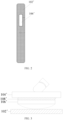
FIG. 1 is a first schematic diagram of a structure of an electronic device in a related technology; -
FIG. 2 is a side view of the electronic device shown inFIG. 1 ; and -
FIG. 3 is a second schematic diagram of a structure of an electronic device in a related technology. - Reference numerals in
FIG. 1 to FIG. 3 :
102': Frame; 104': Foldable screen; 106': Ultrasonic transducer; 108': Metal support mesh. -
FIG. 4 is a diagram of a structural model and a working principle of an ultrasonic fingerprint identification technology; -
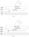
FIG. 5 is a first schematic diagram of a structure of an electronic device according to an embodiment of this application; -
FIG. 6 is a second schematic diagram of a structure of an electronic device according to an embodiment of this application; -
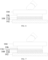
FIG. 7 is a third schematic diagram of a structure of an electronic device according to an embodiment of this application; -
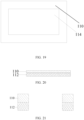
FIG. 8 is a first top view of a reflective support member in an electronic device according to an embodiment of this application; -
FIG. 9 is a second top view of a reflective support member in an electronic device according to an embodiment of this application; -
FIG. 10 is a third top view of a reflective support member in an electronic device according to an embodiment of this application; -
FIG. 11 is a fourth top view of a reflective support member in an electronic device according to an embodiment of this application; -
FIG. 12 is a fifth top view of a reflective support member in an electronic device according to an embodiment of this application; -
FIG. 13 is a first side view of a reflective support member in an electronic device according to an embodiment of this application; -
FIG. 14 is a second side view of a reflective support member in an electronic device according to an embodiment of this application; -
FIG. 15 is a fourth schematic diagram of a structure of an electronic device according to an embodiment of this application; -
FIG. 16 is a fifth schematic diagram of a structure of an electronic device according to an embodiment of this application; -
FIG. 17 is a sixth top view of a reflective support member in an electronic device according to an embodiment of this application; -
FIG. 18 is a seventh top view of a reflective support member in an electronic device according to an embodiment of this application; -
FIG. 19 is an eighth top view of a reflective support member in an electronic device according to an embodiment of this application; -
FIG. 20 is a third side view of a reflective support member in an electronic device according to an embodiment of this application; and -
FIG. 21 is a fourth side view of a reflective support member in an electronic device according to an embodiment of this application. - Reference numerals in
FIG. 4 to FIG. 21 :
102: Frame; 104: Foldable screen; 106: Ultrasonic transducer; 108: Reflective support member; 110: Adhesive; 112: Foam; 114: Hollow; 116: Air layer. - Technical solutions in embodiments of this application are clearly described below with reference to accompanying drawings in the embodiments of this application. Apparently, the described embodiments are some but not all of the embodiments of this application. All other embodiments obtained by a person of ordinary skill in the art based on the embodiments of this application shall fall within the protection scope of this application.
- Terms such as "first" and "second" in this specification and claims of this application are used to distinguish between similar objects instead of describing a specific order or sequence. It should be understood that, data used in such a way is interchangeable in proper circumstances, so that the embodiments of this application can be implemented in an order other than the order illustrated or described herein. Objects classified by "first", "second", and the like are usually of a same type, and the number of objects is not limited. For example, there may be one or more first objects. In addition, in this specification and the claims, "and/or" indicates at least one of connected objects, and a character "/" generally indicates an "or" relationship between associated objects.
- With reference to the accompanying drawings, an electronic device provided in the embodiments of this application is described below in detail by using specific examples and application scenarios thereof. In
FIG. 4 and FIG. 5 , TX1 indicates an ultrasonic wave emitted toward a fingerprint valley, and RX1 indicates a reflected ultrasonic wave of TX1. TX2 indicates an ultrasonic wave emitted toward a fingerprint ridge, and RX2 indicates a reflected ultrasonic wave of TX2. TX3 indicates an ultrasonic wave emitted toward a side of aframe 102, and RX3 indicates a reflected ultrasonic wave of TX3. Z1 indicates acoustic impedance of anultrasonic transducer 106, Z2 indicates acoustic impedance of an air layer, and Z3 indicates acoustic impedance of areflective support member 108. Dashed lines inFIG. 3 andFIG. 5 indicate deformation. - Before the technical solutions defined in this application are described, a structural model and a working principle of an ultrasonic fingerprint identification technology are first briefly described for ease of understanding of a to-be-resolved problem and a technical effect of this application.
- Specifically, as shown in
FIG. 4 , a core component of a fingerprint identification module is theultrasonic transducer 106, and theultrasonic transducer 106 has two functions: one is to transmit ultrasonic waves under an effect of an external electric field, and the other is to pick up an ultrasonic signal that is reflected back and convert the ultrasonic signal into an electrical signal. The ultrasonic transducer is tightly attached to a back surface (a non-display surface) of afoldable screen 104 by using glue or double-sided tape (usually thin in thickness). "Tightly attached" means that there are no bubbles, voids, or foreign matter between attaching surfaces, or an impact of sizes and the number of bubbles, voids, or foreign matter on fingerprint identification performance is minimal and within an acceptable range. - In addition, there are at least two directions for ultrasonic waves transmitted by the ultrasonic transducer. In one direction, an ultrasonic wave is emitted toward the
foldable screen 104, and may reach, after penetrating thefoldable screen 104, a surface of a finger pressed on thefoldable screen 104. In another direction, an ultrasonic wave is emitted away from thefoldable screen 104, and this part of energy is to be recycled and reused. In order to recycle and reuse the ultrasonic wave emitted away from thefoldable screen 104, a layer of gap is usually reserved on a back surface of the ultrasonic transducer to form an air gap. It is assumed that acoustic impedance of a material of the back surface of the ultrasonic transducer is Z1, and acoustic impedance of air is Z2. Because the material of the back surface of the ultrasonic transducer is usually a metal electrode material and an insulating protection coating, the acoustic impedance Z 1 of the material of the back surface of the ultrasonic transducer is far greater than the acoustic impedance Z2 of the air. A reflection coefficient R1 of an interface between the ultrasonic transducer and the air gap may be estimated according to a reflection ratio calculation formula of the ultrasonic wave.
- It can be learned that, because of existence of the air gap, the ultrasonic wave TX3 emitted away from the
foldable screen 104 is completely reflected on the interface of the air gap, and the reflected ultrasonic wave RX3 is emitted toward thefoldable screen 104. In this way, efficiency of the ultrasonic transducer can be improved. This is the mechanism of recycling and reusing of the ultrasonic wave. - Further, as shown in
FIG. 4 , the ultrasonic wave TX1 and the ultrasonic wave TX2 that are emitted toward thefoldable screen 104 reach the surface of the finger after penetrating thefoldable screen 104. A part of the ultrasonic wave TX1 reaches the fingerprint valley (there is an air gap between the fingerprint valley and the foldable screen 104), and is completely reflected when meeting air, and energy of the reflected ultrasonic wave RX1 is relatively strong. Apart of the ultrasonic wave TX2 reaches the fingerprint ridge and meets human tissue (whose acoustic impedance is greater than that of the air but less than that of the foldable screen 104) such as skin and muscle, a reflection ratio at the fingerprint ridge is less than that at the fingerprint valley, and energy of the reflected ultrasonic wave RX2 is weaker than that of RX1. The ultrasonic transducer picks up reflected ultrasonic waves, and may form a light-and-dark fingerprint pattern based on energy of ultrasonic waves at different locations. - It can be learned from the foregoing design solution that, the back surface of the ultrasonic transducer is suspended. When the
foldable screen 104 is soft, a dent is likely to occur during fingerprint identification, causing damage to thefoldable screen 104 and the ultrasonic transducer. - As shown in
FIG. 5 , an embodiment of this application provides an electronic device, including aframe 102, afoldable screen 104, anultrasonic transducer 106, and areflective support member 108. Thefoldable screen 104 is disposed above theframe 102, and there is a distance between thefoldable screen 104 and theframe 102. Thereflective support member 108 is disposed between theultrasonic transducer 106 and theframe 102, and may be configured to support theultrasonic transducer 106. In addition, theultrasonic transducer 106 may transmit ultrasonic waves and receive reflected ultrasonic waves during use. In particular, most of ultrasonic waves transmitted by theultrasonic transducer 106 are emitted toward thefoldable screen 104, and a few are emitted toward theframe 102. An ultrasonic wave emitted toward theframe 102 is emitted toward thereflective support member 108 and completely reflected on an interface of thereflective support member 108, and then also emitted toward thefoldable screen 104. - In particular, as shown in
FIG. 5 , in the electronic device provided in this application, theultrasonic transducer 106 is disposed between thefoldable screen 104 and theframe 102, and theultrasonic transducer 106 is located at a bottom of thefoldable screen 104, and is located on a non-display side of thefoldable screen 104, to implement an under-display fingerprint identification technology of the electronic device with thefoldable screen 104. - In addition, as shown in
FIG. 5 , thereflective support member 108 between thefoldable screen 104 and theframe 102 may be configured to support theultrasonic transducer 106. In this way, when external force is applied to thefoldable screen 104, thereflective support member 108 can provide support for theultrasonic transducer 106 to some extent, to prevent thefoldable screen 104 and theultrasonic transducer 106 from being broken and damaged due to excessively large mechanical deformation, thereby ensuring use security of theultrasonic transducer 106 and the whole electronic device. - In addition, as shown in
FIG. 5 , theultrasonic transducer 106 has high reflection performance. In this way, when being in contact with theultrasonic transducer 106, an ultrasonic wave emitted toward the frame is completely reflected, and is emitted toward thefoldable screen 104 after a traveling direction is changed. In this way, the ultrasonic wave transmitted by theultrasonic transducer 106 toward theframe 102 can be recycled and reused, to improve working efficiency of theultrasonic transducer 106 and improve accuracy of fingerprint identification. - Therefore, in this application, the
reflective support member 108 is disposed between theultrasonic transducer 106 and theframe 102, and theultrasonic transducer 106 is supported and protected by thereflective support member 108. In addition, the ultrasonic wave transmitted by theultrasonic transducer 106 toward theframe 102 is recycled and reused by using thereflective support member 108. In this way, the electronic device with thefoldable screen 104 provided in this application can implement the under-display fingerprint identification technology, and a service life of theultrasonic transducer 106 and the electronic device can be prolonged. - Specifically, as shown in
FIG. 5 , theultrasonic transducer 106 may transmit ultrasonic waves to theframe 102 and thefoldable screen 104 under an effect of an external electric field. In addition, theultrasonic transducer 106 may pick up reflected ultrasonic waves and convert the reflected ultrasonic waves into electrical signals. Theultrasonic transducer 106 picks up the reflected ultrasonic waves, and may form a light-and-dark fingerprint pattern based on energy of ultrasonic waves at different locations, to implement fingerprint identification. - In a possible implementation, the
foldable screen 104 includes a first area (not shown in the figure) and a second area (not shown in the figure). The first area is foldable and is used as a foldable area of thefoldable screen 104, and the second area is not foldable and is used as a non-foldable area of thefoldable screen 104. In particular, in the electronic device provided in this application, theultrasonic transducer 106 is disposed between the second area and theframe 102. - Therefore, in this application, the
ultrasonic transducer 106 is disposed in the non-foldable area of thefoldable screen 104. In this way, in a process of using the electronic device, a user does not affect security of theultrasonic transducer 106 when folding thefoldable screen 104, and does not affect use of theultrasonic transducer 106, thereby greatly improving use security of theultrasonic transducer 106 and the whole electronic device. - In a possible implementation, as shown in
FIG. 5 , acoustic impedance of thereflective support member 108 is less than acoustic impedance of theultrasonic transducer 106. In addition, the acoustic impedance of thereflective support member 108 is far less than the acoustic impedance of theultrasonic transducer 106. Specifically, acoustic impedance of an interface, facing a side of theultrasonic transducer 106, of thereflective support member 108 is far less than acoustic impedance of a material of a surface, facing a side of thereflective support member 108, of theultrasonic transducer 106. In this way, compared with the acoustic impedance of theultrasonic transducer 106, the acoustic impedance of thereflective support member 108 may even be ignored. - In this case, the ultrasonic wave transmitted by the
ultrasonic transducer 106 toward theframe 102 may be completely reflected when meeting thereflective support member 108, so that maximal ultrasonic waves can be recycled and reused, to maximize utilization of ultrasonic waves, improve working efficiency of theultrasonic transducer 106, and improve accuracy of fingerprint identification. - It should be noted that, as shown in
FIG. 5 , the interface, facing the side of theultrasonic transducer 106, of thereflective support member 108 is smooth and flat, thereby ensuring evenness of the interface. Generally, sizes of surface pits or pores on the interface, facing the side of theultrasonic transducer 106, of thereflective support member 108 are smaller than a pixel size of theultrasonic transducer 106. In this way, even if reflected ultrasonic noise formed by the pits or the pores is picked up by theultrasonic transducer 106, fingerprint image quality is not seriously affected. A person skilled in the art can understand the foregoing requirements, and details are not described herein. - In a possible implementation, as shown in
FIG. 6 andFIG. 15 , theultrasonic transducer 106 is attached to thereflective support member 108, and the acoustic impedance of thereflective support member 108 is far less than the acoustic impedance of theultrasonic transducer 106. In this way, the ultrasonic wave transmitted by theultrasonic transducer 106 toward theframe 102 may be completely reflected when meeting thereflective support member 108, so that maximal ultrasonic waves can be recycled and reused. - In a possible implementation, as shown in
FIG. 7 andFIG. 16 , there is anair layer 116 between theultrasonic transducer 106 and thereflective support member 108, and the acoustic impedance of thereflective support member 108 is far less than acoustic impedance of theair layer 116. In this way, the ultrasonic wave transmitted by theultrasonic transducer 106 toward theframe 102 may be completely reflected when meeting theair layer 116, so that maximal ultrasonic waves can be recycled and reused. - Specifically, as shown in
FIG. 7 , theair layer 116 may exist between a whole area of theultrasonic transducer 106 and thereflective support member 108. Alternatively, as shown inFIG. 16 , theair layer 116 may exist between a local area of theultrasonic transducer 106 and thereflective support member 108. - In a possible implementation, as shown in
FIG. 5 , thereflective support member 108 is an elastic layer, and has elasticity or flexibility. The elastic layer may be compressed when external force is applied, and the elastic layer may be completely or at least partially restored to a free state when the external force is withdrawn. - In a possible implementation, as shown in
FIG. 6 , a free-state thickness (that is, a natural thickness of the elastic layer in a case that there is no external force) of the elastic layer may be greater than or equal to a distance between theultrasonic transducer 106 and theframe 102. That is, in a case that the electronic device is assembled completely and the user does not press thefoldable screen 104, thereflective support member 108 can be always in contact with theultrasonic transducer 106. In this way, consistency and stability of recycling and reusing of ultrasonic waves emitted away from thefoldable screen 104 can be ensured. - In a possible implementation, as shown in
FIG. 7 , the free-state thickness (that is, the natural thickness of the elastic layer in the case that there is no external force) of the elastic layer may be less than the distance between theultrasonic transducer 106 and theframe 102. That is, in a case that the user does not press thefoldable screen 104 or the user presses with relatively weak force, thereflective support member 108 is separated from theultrasonic transducer 106, and it is ensured that there is an air gap between thereflective support member 108 and theultrasonic transducer 106. When the user presses with relatively strong force, theultrasonic transducer 106 generates large mechanical deformation, and theultrasonic transducer 106 is in close contact with thereflective support member 108. - In this way, a condition of total internal reflection is provided by air when finger pressing force is relatively weak, and a reflective interface is even and imaging quality is high. When finger pressing force is strong, a condition of total internal reflection is provided by the
reflective support member 108. Although evenness is lower than that of the air, thereflective support member 108 can cushion mechanical deformation of theultrasonic transducer 106, to avoid damage to theultrasonic transducer 106. - Specifically, the free-state thickness is further explained as follows: In a case that the user does not press the
foldable screen 104 or the user presses with relatively weak force, thefoldable screen 104 does not squeeze theultrasonic transducer 106 and thereflective support member 108, and in this state, a thickness of thereflective support member 108 is the foregoing free-state thickness. That is, the free-state thickness may be understood as a thickness in a natural state, that is, a thickness of thereflective support member 108 without deformation. - In a possible implementation, as shown in
FIG. 15 and FIG. 16 , thereflective support member 108 may be connected to theultrasonic transducer 106. In this case, in a process of assembling the electronic device, thereflective support member 108 is first attached to a specified position of a back surface of theultrasonic transducer 106, and then thefoldable screen 104 and theultrasonic transducer 106 are assembled to theframe 102. In particular, thereflective support member 108 is directly attached to the back surface of theultrasonic transducer 106, and then is assembled to theframe 102, making assembly simpler. - Specifically, as shown in
FIG. 15 and FIG. 16 , thereflective support member 108 is tightly attached to theultrasonic transducer 106. "Tightly attached" means that there are no bubbles, voids, or foreign matter between attaching surfaces of thereflective support member 108 and theultrasonic transducer 106, or an impact of sizes and the number of bubbles, voids, or foreign matter on fingerprint identification performance is minimal and within an acceptable range. - In a possible implementation, as shown in
FIG. 6 and FIG. 7 , thereflective support member 108 may be connected to theframe 102. In this case, in a process of assembling the electronic device, thereflective support member 108 is first attached to a specified position of theframe 102, and then thefoldable screen 104 and theultrasonic transducer 106 are assembled to theframe 102. In particular, thereflective support member 108 is attached to theframe 102, helping theultrasonic transducer 106 with recycling and reusing of ultrasonic waves emitted away from thefoldable screen 104, and providing structural support for thefoldable screen 104 and theultrasonic transducer 106, thereby improving reliability of the electronic device. - Specifically, as shown in
FIG. 6 and FIG. 7 , thereflective support member 108 is tightly attached to theframe 102. "Tightly attached" means that there are no bubbles, voids, or foreign matter between attaching surfaces of thereflective support member 108 and theframe 102, or an impact of sizes and the number of bubbles, voids, or foreign matter on fingerprint identification performance is minimal and within an acceptable range. - In a possible implementation, as shown in
FIG. 13, FIG. 14 ,FIG. 20, and FIG. 21 , thereflective support member 108 includes an adhesive 110 andfoam 112 that are connected to each other. Thefoam 112 may be connected to theultrasonic transducer 106 through the adhesive 110, or may be connected to theframe 102 through the adhesive 110. Specifically, the adhesive 110 may be a silicone adhesive, a pressure-sensitive adhesive, or the like, to ensure that thefoam 112 is stably connected to theultrasonic transducer 106 or theframe 102. In addition, thefoam 112 has good elasticity and plasticity. When thefoldable screen 104 is pressed by a finger, mechanical deformation of theultrasonic transducer 106 may be cushioned through deformation of thefoam 112, to avoid damage to theultrasonic transducer 106. - In a possible implementation, the
ultrasonic transducer 106 includes a third area (not shown in the figure) and a fourth area (not shown in the figure). The third area may transmit and receive ultrasonic waves, and the third area is an effective working area of theultrasonic transducer 106. - In a possible implementation, as shown in
FIG. 8 andFIG. 17 , thefoam 112 may completely cover the third area, that is, thefoam 112 completely covers the effective working area of theultrasonic transducer 106. In this case, thefoam 112 may be in contact with all positions of the third area, to ensure good consistency of transmitting efficiency of ultrasonic waves in the positions of the third area, and further ensure uniformity and consistency of fingerprint image quality. - In a possible implementation, as shown in
FIG. 9 ,FIG. 10 ,FIG. 11 , andFIG. 18 , thefoam 112 may partially cover the third area, that is, thefoam 112 partially covers the effective working area of theultrasonic transducer 106. In this case, a part, in contact with the third area, of thefoam 112 may provide good mechanical support for theultrasonic transducer 106, and a part, separated from the third area, of thefoam 112 actually forms an air gap. The air gap provides a good condition of total internal reflection for ultrasonic waves emitted away from thefoldable screen 104. - In a possible implementation, as shown in
FIG. 12 andFIG. 19 , thefoam 112 may avoid the third area, that is, thefoam 112 avoids the effective working area of theultrasonic transducer 106. In this case, an air gap may provide a good condition of total internal reflection for ultrasonic waves emitted away from thefoldable screen 104. - In a possible implementation, when the
foam 112 partially covers the third area, a hollow 114 is provided on thefoam 112, and the hollow 114 covers the third area. - Specifically, as shown in
FIG. 9 andFIG. 18 , thefoam 112 may be designed as a grid shape.Cross-shaped foam 112 in the middle provides mechanical support for a central area of the third area, and surroundinghollows 114 actually form air gaps. - In addition, as shown in
FIG. 10 and FIG. 11 , thefoam 112 may be in another shape, for example, the hollow 114 in the middle may be an octagon, a circle, or even in an irregular shape. These two shapes can provide better mechanical support for four corners of the third area. Generally, a contact area between the finger and thefoldable screen 104 is approximately circular or oval, and the four corners of the third area provide no useful image. Therefore, contact of thefoam 112 with the four corners has no significantly negative impact on fingerprint image quality. - In a possible implementation, as shown in
FIG. 17, FIG. 18 , andFIG. 19 , when thereflective support member 108 is connected to theultrasonic transducer 106, the adhesive 110 is at least connected to the fourth area, so that the adhesive 110 is connected to a non-effective working area of theultrasonic transducer 106. A hollow 114 is provided on the adhesive 110, so that the adhesive 110 does not affect total internal reflection of ultrasonic waves transmitted by theultrasonic transducer 106 toward theframe 102. In addition, thefoam 112 may be in direct contact with the third area of theultrasonic transducer 106, or a gap may be reserved between thefoam 112 and the third area of theultrasonic transducer 106. - In a possible implementation, an attaching surface, facing a side of the
frame 102, of thefoldable screen 104 is a metal surface. In this way, the metal surface can ensure that thefoldable screen 104 has good strength, thereby ensuring a service life of thefoldable screen 104. In addition, an ultrasonic wave may travel through metal, so that the metal screen does not affect working of theultrasonic transducer 106. Specifically, the attaching surface, facing the side of theframe 102, of thefoldable screen 104 may be a steel sheet, an alloy sheet, or the like. - In a possible implementation, the
frame 102 is a middle frame. That is, theultrasonic transducer 106 is disposed between the middle frame and thefoldable screen 104. - In a related technology, as shown in
FIG. 1 andFIG. 2 , an ultrasonic transducer 106' is mainly disposed on a side of an electronic device with a foldable screen 104', to implement a fingerprint identification function. However, appearance of the side is greatly damaged by the ultrasonic transducer 106', and appearance appeal is far lower than that of an electronic device applying an under-display fingerprint identification technology. Specifically, there are two main factors that limit application of the under-display fingerprint identification technology to the electronic device with the foldable screen 104'. - A first factor is as follows: As shown in
FIG. 3 , the foldable screen 104' used in the electronic device is soft, and a metal support mesh 108' is needed to support and protect a back surface of the foldable screen 104'. An optical fingerprint identification technology cannot work through a metal layer. - A second factor is as follows: As shown in
FIG. 3 , when an ultrasonic fingerprint identification technology is used, a sound wave transducer of the ultrasonic transducer 106' needs to be directly attached to the back surface of the foldable screen 104'. The foldable screen 104' is soft and prone to deformation, and cannot provide enough mechanical protection for the sound wave transducer. When the user performs unlocking, the foldable screen 104' and the ultrasonic transducer 106' are deformed, and when mechanical deformation of the ultrasonic transducer 106' is excessively large, the ultrasonic transducer 106' is broken because the deformation exceeds a limit or the ultrasonic transducer 106' collides with a structural member such as a frame 102'. - Therefore, as shown in
FIG. 5 , this application provides an electronic device with afoldable screen 104, to which an under-display fingerprint identification technology can be applied. Specifically, anultrasonic transducer 106 is disposed on a back surface of thefoldable screen 104 of the electronic device, and theultrasonic transducer 106 is tightly attached to thefoldable screen 104 by using a material such as glue or tape. Theultrasonic transducer 106 is located in a non-foldable area of thefoldable screen 104, and theultrasonic transducer 106 is located between thefoldable screen 104 and aframe 102. There is areflective support member 108 between the ultrasonic transducer and theframe 102, and thereflective support member 108 reflects an ultrasonic wave transmitted by a back surface of theultrasonic transducer 106, and provides structural support for theultrasonic transducer 106 and thefoldable screen 104 to avoid excessively large deformation. - Specifically, as shown in
FIG. 5 , in the electronic device provided in this embodiment of this application, theultrasonic transducer 106 is tightly attached to the back surface (a non-display surface) of thefoldable screen 104 by using glue or double-sided tape (usually thin in thickness and not shown in the figure) in the non-foldable area of thefoldable screen 104. The attaching surface of thefoldable screen 104 may be a metal layer such as a steel sheet or an alloy, because an ultrasonic wave may travel through metal. - In addition, as shown in
FIG. 5 , theultrasonic transducer 106 is located between thefoldable screen 104 and theframe 102, and thereflective support member 108 is disposed between theultrasonic transducer 106 and theframe 102. Thereflective support member 108 may be in close contact with at least one of theultrasonic transducer 106 and theframe 102. Acoustic impedance Z3 of a surface, in contact with theultrasonic transducer 106, of thereflective support member 108 needs to be far less than acoustic impedance Z1 of a material of the back surface of theultrasonic transducer 106, that is, Z3<<Z1. An objective of this design is to implement total internal reflection of an ultrasonic wave on a contact interface between theultrasonic transducer 106 and thereflective support member 108, thereby implementing recycling and reusing of ultrasonic waves emitted away from thefoldable screen 104. - In addition, the surface, in contact with the
ultrasonic transducer 106, of thereflective support member 108 needs to be smooth and flat, to ensure evenness of the interface. Generally, sizes of pits or pores on the surface, in contact with theultrasonic transducer 106, of thereflective support member 108 need to be smaller than a pixel size of theultrasonic transducer 106. In this way, even if reflected ultrasonic noise formed by the pits or the pores is picked up by theultrasonic transducer 106, fingerprint image quality is not seriously affected. - In addition, as shown in
FIG. 5 , thereflective support member 108 further has flexibility or elasticity, and may be compressed when external force is applied, and may be completely or at least partially restored to a free state when the external force is withdrawn. In particular, because thereflective support member 108 is disposed between theultrasonic transducer 106 and theframe 102, when thefoldable screen 104 is pressed by a finger during fingerprint identification, thereflective support member 108 can provide structural support to some extent, to prevent thefoldable screen 104 and theultrasonic transducer 106 from being broken and damaged due to excessively large mechanical deformation. In addition, even if theultrasonic transducer 106 generates excessively large mechanical deformation, theultrasonic transducer 106 is not directly hit thehard frame 102 to be broken, because thereflective support member 108 is soft enough to cushion such hit. - The technical solutions defined in this application are further described below by using two specific embodiments.
- As shown in
FIG. 6 and FIG. 7 , in a first specific embodiment, thereflective support member 108 includes a two-layer structure. A layer close to theultrasonic transducer 106 isfoam 112, and a layer close to theframe 102 is an adhesive 110 (for example, a silicone adhesive or a pressure-sensitive adhesive). Thefoam 112 is attached to theframe 102 by using the adhesive 110. During assembly, thereflective support member 108 is first attached to a specified position of theframe 102, and then thefoldable screen 104 and theultrasonic transducer 106 are assembled. - In this embodiment, as shown in
FIG. 6 , a free-state thickness of thereflective support member 108 may be not less than a gap between theultrasonic transducer 106 and theframe 102, to ensure that thefoam 112 of thereflective support member 108 can be always in contact with theultrasonic transducer 106 after assembly is completed. In addition, as shown inFIG. 7 , the free-state thickness of thereflective support member 108 may be less than the gap between theultrasonic transducer 106 and theframe 102. When no finger is pressed or pressing force is relatively weak, an air gap is still reserved between theultrasonic transducer 106 and thereflective support member 108. When finger pressing force is relatively strong, theultrasonic transducer 106 generates relatively large mechanical deformation, and theultrasonic transducer 106 is in close contact with thereflective support member 108. - In this embodiment, as shown in
FIG. 8 , thefoam 112 may completely cover an effective working area of theultrasonic transducer 106. Alternatively, as shown inFIG. 9 ,FIG. 10, and FIG. 11 , thefoam 112 may partially cover the effective working area of theultrasonic transducer 106. Alternatively, as shown inFIG. 12 , thefoam 112 may not cover the effective working area of theultrasonic transducer 106. - In this embodiment, the
reflective support member 108 is attached to theframe 102, helping theultrasonic transducer 106 with recycling and reusing of ultrasonic waves emitted away from thefoldable screen 104, and providing structural support for thefoldable screen 104 and theultrasonic transducer 106, thereby improving reliability of the electronic device. - As shown in
FIG. 15 and FIG. 16 , in a second specific embodiment, thereflective support member 108 includes a two-layer structure. A layer close to theultrasonic transducer 106 is an adhesive 110 (for example, a silicone adhesive or a pressure-sensitive adhesive), and a layer close to a middle frame isfoam 112. The adhesive 110 has a hollow 114 in an effective working area of theultrasonic transducer 106, and thefoam 112 does not necessarily have a hollow 114 in the effective working area. Thefoam 112 is attached to the back surface of theultrasonic transducer 106 by using the adhesive 110. During assembly, thereflective support member 108 is first attached to a specified position of the back surface of theultrasonic transducer 106, and then thefoldable screen 104 and theultrasonic transducer 106 are assembled to the middle frame. - In this embodiment, as shown in
FIG. 15 and FIG. 16 , thereflective support member 108 includes the two-layer structure. The layer close to theultrasonic transducer 106 is the adhesive 110 (for example, the silicone adhesive or the pressure-sensitive adhesive), and the layer close to theframe 102 is thefoam 112. The adhesive 110 has the hollow 114 in the effective working area of theultrasonic transducer 106, and thefoam 112 does not necessarily have a hollow 114 in the effective working area of theultrasonic transducer 106. Thefoam 112 is attached to the back surface of the ultrasonic transducer by using the adhesive 110. During assembly, thereflective support member 108 is first attached to the specified position of the back surface of the ultrasonic transducer, and then thefoldable screen 104 and the ultrasonic transducer are assembled to theframe 102. - In this embodiment, as shown in
FIG. 17 , thefoam 112 may completely cover the effective working area of theultrasonic transducer 106. Alternatively, as shown inFIG. 18 , thefoam 112 may partially cover the effective working area of theultrasonic transducer 106. Alternatively, as shown inFIG. 19 , thefoam 112 may not cover the effective working area of theultrasonic transducer 106. - In this embodiment, the
reflective support member 108 is directly attached to the back surface of theultrasonic transducer 106, and then is assembled to theframe 102, making assembly simpler. - In the description of this specification, the description with reference to the terms such as "an embodiment", "some embodiments", "an illustrative embodiment", "an example", "a specific example", or "some examples" means that a specific feature, a structure, a material, or a characteristic described with reference to the embodiment or example is included in at least one embodiment or example of this application. In this specification, the foregoing example expressions of the terms are not necessarily with respect to a same embodiment or example. In addition, the described specific features, structures, materials, or characteristics may be combined in a proper manner in any one or more of the embodiments or examples.
- Although the embodiments of this application have been illustrated and described, a person of ordinary skill in the art can understand that various changes, modifications, replacements, and variants may be made to these embodiments without departing from the principle and purpose of this application, and the scope of this application is limited by the claims and their equivalents.
Claims (12)
- An electronic device, comprising:a frame;a foldable screen, disposed above the frame;an ultrasonic transducer, disposed between the frame and the foldable screen, and configured to transmit and receive ultrasonic waves; anda reflective support member, disposed between the ultrasonic transducer and the frame, and configured to support the ultrasonic transducer, wherein at least some of ultrasonic waves emitted toward the frame are completely reflected by the reflective support member and then are emitted toward the foldable screen.
- The electronic device according to claim 1, whereinthe foldable screen comprises a first area and a second area, and the first area is foldable; andthe ultrasonic transducer is located between the second area and the frame.
- The electronic device according to claim 1, wherein
acoustic impedance of the reflective support member is less than acoustic impedance of the ultrasonic transducer. - The electronic device according to any one of claims 1 to 3, whereinthe ultrasonic transducer is attached to the reflective support member; oran air layer exists between the ultrasonic transducer and the reflective support member.
- The electronic device according to any one of claims 1 to 3, whereinthe reflective support member is an elastic layer; anda free-state thickness of the elastic layer is greater than or equal to a distance between the ultrasonic transducer and the frame.
- The electronic device according to any one of claims 1 to 3, whereinthe reflective support member is an elastic layer; anda free-state thickness of the elastic layer is less than a distance between the ultrasonic transducer and the frame.
- The electronic device according to any one of claims 1 to 3, whereinthe reflective support member is connected to the ultrasonic transducer; orthe reflective support member is connected to the frame.
- The electronic device according to claim 7, whereinthe reflective support member comprises an adhesive and foam that are connected to each other; andthe foam is connected to the ultrasonic transducer or the frame through the adhesive.
- The electronic device according to claim 8, whereinthe ultrasonic transducer comprises a third area and a fourth area, and the third area is configured to transmit ultrasonic waves; andthe foam completely covers the third area, or partially covers the third area, or avoids the third area.
- The electronic device according to claim 9, wherein
when the foam completely or partially covers the third area, a hollow is provided on the foam, and the hollow covers the third area. - The electronic device according to claim 9, wherein
when the reflective support member is connected to the ultrasonic transducer, a hollow is provided on the adhesive, and the foam is in contact with or separated from the third area. - The electronic device according to any one of claims 1 to 3, wherein
an attaching surface, facing a side of the frame, of the foldable screen is a metal surface.
Applications Claiming Priority (2)
| Application Number | Priority Date | Filing Date | Title |
|---|---|---|---|
| CN202111000694.5A CN113672042B (en) | 2021-08-30 | 2021-08-30 | Electronic equipment |
| PCT/CN2022/114707 WO2023030150A1 (en) | 2021-08-30 | 2022-08-25 | Electronic device |
Publications (2)
| Publication Number | Publication Date |
|---|---|
| EP4398065A1 true EP4398065A1 (en) | 2024-07-10 |
| EP4398065A4 EP4398065A4 (en) | 2024-11-27 |
Family
ID=78547210
Family Applications (1)
| Application Number | Title | Priority Date | Filing Date |
|---|---|---|---|
| EP22863288.1A Pending EP4398065A4 (en) | 2021-08-30 | 2022-08-25 | ELECTRONIC DEVICE |
Country Status (4)
| Country | Link |
|---|---|
| US (1) | US20240184333A1 (en) |
| EP (1) | EP4398065A4 (en) |
| CN (1) | CN113672042B (en) |
| WO (1) | WO2023030150A1 (en) |
Families Citing this family (3)
| Publication number | Priority date | Publication date | Assignee | Title |
|---|---|---|---|---|
| CN113672042B (en) * | 2021-08-30 | 2024-05-17 | 维沃移动通信有限公司 | Electronic equipment |
| KR20240059762A (en) * | 2022-10-26 | 2024-05-08 | 삼성디스플레이 주식회사 | Display device including fingerprint detection sensor |
| CN115981504B (en) * | 2023-01-30 | 2025-09-19 | 维沃移动通信有限公司 | Electronic device and detection method thereof |
Family Cites Families (13)
| Publication number | Priority date | Publication date | Assignee | Title |
|---|---|---|---|---|
| US8264126B2 (en) * | 2009-09-01 | 2012-09-11 | Measurement Specialties, Inc. | Multilayer acoustic impedance converter for ultrasonic transducers |
| US9513746B2 (en) * | 2012-07-31 | 2016-12-06 | Elo Touch Solutions, Inc. | Touch sensitive display with acoustic isolation |
| US10036734B2 (en) * | 2013-06-03 | 2018-07-31 | Snaptrack, Inc. | Ultrasonic sensor with bonded piezoelectric layer |
| US9984271B1 (en) * | 2014-09-30 | 2018-05-29 | Apple Inc. | Ultrasonic fingerprint sensor in display bezel |
| US20180373913A1 (en) * | 2017-06-26 | 2018-12-27 | Qualcomm Incorporated | Ultrasonic fingerprint sensor for under-display applications |
| CN109492501A (en) * | 2017-09-12 | 2019-03-19 | 南昌欧菲生物识别技术有限公司 | Electronic equipment |
| US11175769B2 (en) * | 2018-08-16 | 2021-11-16 | Apple Inc. | Electronic device with glass enclosure |
| CN111222391A (en) * | 2018-11-27 | 2020-06-02 | 北京小米移动软件有限公司 | Display screen and electronic equipment |
| CN210605745U (en) * | 2018-12-13 | 2020-05-22 | 深圳市汇顶科技股份有限公司 | Fingerprint identification device and electronic equipment |
| CN112466205A (en) * | 2019-09-06 | 2021-03-09 | 华为技术有限公司 | Foldable electronic device and folding screen mounting structure |
| CN210324234U (en) * | 2019-09-18 | 2020-04-14 | 南昌欧菲生物识别技术有限公司 | Ultrasonic fingerprint module and electronic equipment |
| CN111866680B (en) * | 2020-07-15 | 2022-08-30 | 深圳市汇顶科技股份有限公司 | Ultrasonic transducer and electronic equipment |
| CN113672042B (en) * | 2021-08-30 | 2024-05-17 | 维沃移动通信有限公司 | Electronic equipment |
-
2021
- 2021-08-30 CN CN202111000694.5A patent/CN113672042B/en active Active
-
2022
- 2022-08-25 WO PCT/CN2022/114707 patent/WO2023030150A1/en not_active Ceased
- 2022-08-25 EP EP22863288.1A patent/EP4398065A4/en active Pending
-
2024
- 2024-02-14 US US18/441,010 patent/US20240184333A1/en active Pending
Also Published As
| Publication number | Publication date |
|---|---|
| CN113672042B (en) | 2024-05-17 |
| WO2023030150A1 (en) | 2023-03-09 |
| EP4398065A4 (en) | 2024-11-27 |
| CN113672042A (en) | 2021-11-19 |
| US20240184333A1 (en) | 2024-06-06 |
Similar Documents
| Publication | Publication Date | Title |
|---|---|---|
| US20240184333A1 (en) | Electronic device | |
| EP2866351B1 (en) | Electronic device | |
| US20150023527A1 (en) | Electronic apparatus | |
| WO2022121882A1 (en) | Electronic device | |
| CN110183993A (en) | Screen protecting film and electronic equipment | |
| CN209448767U (en) | Mobile terminal | |
| US20250143185A1 (en) | Piezoelectric vibration sensing unit and electronic device | |
| WO2023274114A1 (en) | Electronic device | |
| CN112489559B (en) | Supporting structure and display device | |
| CN210324234U (en) | Ultrasonic fingerprint module and electronic equipment | |
| WO2025214276A1 (en) | Flexible screen module and electronic device | |
| CN214477541U (en) | Electronic equipment and its display | |
| CN217116127U (en) | Middle frame of electronic equipment and electronic equipment | |
| CN216775033U (en) | Circuit board assembly, microphone and electronic equipment | |
| CN207182312U (en) | Ultrasonic wave biological identification device and electronic equipment | |
| CN216119532U (en) | Plane vibration piezoelectric ceramic buzzer | |
| CN109982180A (en) | Microphone waterproof assembling structure and smart electronics product | |
| CN114612947A (en) | Fingerprint identification subassembly and electronic equipment | |
| CN210534811U (en) | Glass pastes structure of supplementary ultrasonic wave fingerprint response | |
| CN209825495U (en) | Mobile phone information security manager | |
| CN213244093U (en) | Cell phone case with better protection performance | |
| CN217628201U (en) | Rupture membrane for mobile phone rear cover | |
| CN216649925U (en) | Microphone (CN) | |
| CN222760136U (en) | Protective components, hinge components and smart terminals | |
| US20250193580A1 (en) | Bone conduction microphone |
Legal Events
| Date | Code | Title | Description |
|---|---|---|---|
| STAA | Information on the status of an ep patent application or granted ep patent |
Free format text: STATUS: THE INTERNATIONAL PUBLICATION HAS BEEN MADE |
|
| PUAI | Public reference made under article 153(3) epc to a published international application that has entered the european phase |
Free format text: ORIGINAL CODE: 0009012 |
|
| STAA | Information on the status of an ep patent application or granted ep patent |
Free format text: STATUS: REQUEST FOR EXAMINATION WAS MADE |
|
| 17P | Request for examination filed |
Effective date: 20240222 |
|
| AK | Designated contracting states |
Kind code of ref document: A1 Designated state(s): AL AT BE BG CH CY CZ DE DK EE ES FI FR GB GR HR HU IE IS IT LI LT LU LV MC MK MT NL NO PL PT RO RS SE SI SK SM TR |
|
| A4 | Supplementary search report drawn up and despatched |
Effective date: 20241030 |
|
| RIC1 | Information provided on ipc code assigned before grant |
Ipc: G06V 40/13 20220101ALI20241024BHEP Ipc: H04M 1/02 20060101ALI20241024BHEP Ipc: G06F 1/16 20060101AFI20241024BHEP |
|
| DAV | Request for validation of the european patent (deleted) | ||
| DAX | Request for extension of the european patent (deleted) | ||
| STAA | Information on the status of an ep patent application or granted ep patent |
Free format text: STATUS: EXAMINATION IS IN PROGRESS |
|
| 17Q | First examination report despatched |
Effective date: 20250612 |