EP4398055A1 - Enhanced engine model for control and health monitoring - Google Patents
Enhanced engine model for control and health monitoring Download PDFInfo
- Publication number
- EP4398055A1 EP4398055A1 EP24151034.6A EP24151034A EP4398055A1 EP 4398055 A1 EP4398055 A1 EP 4398055A1 EP 24151034 A EP24151034 A EP 24151034A EP 4398055 A1 EP4398055 A1 EP 4398055A1
- Authority
- EP
- European Patent Office
- Prior art keywords
- engine
- model
- parameters
- self
- calibration
- Prior art date
- Legal status (The legal status is an assumption and is not a legal conclusion. Google has not performed a legal analysis and makes no representation as to the accuracy of the status listed.)
- Granted
Links
Images




Classifications
-
- G—PHYSICS
- G05—CONTROLLING; REGULATING
- G05B—CONTROL OR REGULATING SYSTEMS IN GENERAL; FUNCTIONAL ELEMENTS OF SUCH SYSTEMS; MONITORING OR TESTING ARRANGEMENTS FOR SUCH SYSTEMS OR ELEMENTS
- G05B17/00—Systems involving the use of models or simulators of said systems
- G05B17/02—Systems involving the use of models or simulators of said systems electric
-
- F—MECHANICAL ENGINEERING; LIGHTING; HEATING; WEAPONS; BLASTING
- F02—COMBUSTION ENGINES; HOT-GAS OR COMBUSTION-PRODUCT ENGINE PLANTS
- F02C—GAS-TURBINE PLANTS; AIR INTAKES FOR JET-PROPULSION PLANTS; CONTROLLING FUEL SUPPLY IN AIR-BREATHING JET-PROPULSION PLANTS
- F02C9/00—Controlling gas-turbine plants; Controlling fuel supply in air- breathing jet-propulsion plants
-
- F—MECHANICAL ENGINEERING; LIGHTING; HEATING; WEAPONS; BLASTING
- F05—INDEXING SCHEMES RELATING TO ENGINES OR PUMPS IN VARIOUS SUBCLASSES OF CLASSES F01-F04
- F05D—INDEXING SCHEME FOR ASPECTS RELATING TO NON-POSITIVE-DISPLACEMENT MACHINES OR ENGINES, GAS-TURBINES OR JET-PROPULSION PLANTS
- F05D2260/00—Function
- F05D2260/80—Diagnostics
-
- F—MECHANICAL ENGINEERING; LIGHTING; HEATING; WEAPONS; BLASTING
- F05—INDEXING SCHEMES RELATING TO ENGINES OR PUMPS IN VARIOUS SUBCLASSES OF CLASSES F01-F04
- F05D—INDEXING SCHEME FOR ASPECTS RELATING TO NON-POSITIVE-DISPLACEMENT MACHINES OR ENGINES, GAS-TURBINES OR JET-PROPULSION PLANTS
- F05D2270/00—Control
- F05D2270/70—Type of control algorithm
- F05D2270/71—Type of control algorithm synthesized, i.e. parameter computed by a mathematical model
-
- F—MECHANICAL ENGINEERING; LIGHTING; HEATING; WEAPONS; BLASTING
- F05—INDEXING SCHEMES RELATING TO ENGINES OR PUMPS IN VARIOUS SUBCLASSES OF CLASSES F01-F04
- F05D—INDEXING SCHEME FOR ASPECTS RELATING TO NON-POSITIVE-DISPLACEMENT MACHINES OR ENGINES, GAS-TURBINES OR JET-PROPULSION PLANTS
- F05D2270/00—Control
- F05D2270/80—Devices generating input signals, e.g. transducers, sensors, cameras or strain gauges
- F05D2270/802—Calibration thereof
Definitions
- the self-tuned engine estimation module updates the closed-loop self-tuned engine model using the short-term tuning parameters ( ⁇ ST) independently from the long-term tuning parameters ( ⁇ LT).
- the plurality of different calibration models include an entry into service model that is constructed based on test cell data generated according to an acceptance test, and a service calibration model that is constructed based on flight data collected during operation of the gas turbine engine.
- the regime recognition module initiates a calibration adjustment mode to calibrate the open-loop nominal engine model and the closed-loop self-tuned engine model in response to determining that the identified one or more engine operating conditions were not previously identified.
- the regime recognition module in response to initiating the calibration mode, increases the confidence value of the identified operating conditions.
- the method further includes outputting, via a self-tuned engine estimation module including a closed-loop self-tuned engine model, estimated self-tuned engine parameters (P*est) indicative of the one or more engine operating parameters, and updating the closed-loop self-tuned engine model based on short-term tuning parameters ( ⁇ ST) and long-term tuning parameters ( ⁇ LT).
- a self-tuned engine estimation module including a closed-loop self-tuned engine model, estimated self-tuned engine parameters (P*est) indicative of the one or more engine operating parameters
- P*est estimated self-tuned engine parameters
- ⁇ ST short-term tuning parameters
- ⁇ LT long-term tuning parameters
- the self-tuned engine estimation module updates the closed-loop self-tuned engine model using the short-term tuning parameters ( ⁇ ST) independently from the long-term tuning parameters ( ⁇ LT).
- the method further includes identifying, via a regime recognition module, the engine operating conditions, and selectively updating the open-loop nominal engine model and the closed-loop self-tuned engine model using a calibration adjustment model based on the one or more engine operating conditions identified by the regime recognition module.
- the method further includes selecting, via the regime recognition module, a given calibration model among a plurality of different calibration models based on the identified one or more engine operating conditions, delivering the selected calibration model to a calibration adjustment module, and updating, via the calibration adjustment module, the open-loop nominal engine model and the closed-loop self-tuned engine model based on the selected calibration model.
- the plurality of different calibration models includes an entry into service model that is constructed based on test cell data generated according to an acceptance test, and a service calibration model that is constructed based on flight data collected during operation of the gas turbine engine.
- the method further includes initiating, via the regime recognition module, a calibration adjustment mode to calibrate the open-loop nominal engine model and the closed-loop self-tuned engine model in response to determining that the identified one or more engine operating conditions were not previously identified.
- Self-tuning models such as an aircraft on-board engine models (OBEM) utilize tuning parameters, sometimes referred to simply as “tuners", which are adjustments to various engine's physical parameters including, for example, component efficiencies and flow capacities.
- OBEM aircraft on-board engine models
- tuning parameters sometimes referred to simply as “tuners”
- these self-tuning models often suffer from "tuner contamination,” which refers to a problem that occurs when the self-tuning models attempt compensate for various uncertainties such as engine to engine variation, measurement error, and model infidelity to name a few. Consequently, the tuners essentially lose their physical meanings or physical "truths,” which reduces their value and reliability when performing engine health assessment.
- One way to preserve the physical meaning of the tuners is to calibrate the model before use so that it absorbs as maximum number of uncertainties as possible. This is usually achieved by using the actual field data in the context of a "Digital Twin" concept and leveraging Machine Learning techniques.
- conventional dynamic model calibration techniques suffer from two significant challenges.
- the self-tuning capability will diminish proportionally to the engine deterioration.
- the tuners are often range limited to prevent undesirable adjustments being applied, which in turn reduces the tunning capabilities, particularly when the engine deterioration gets larger.
- gas turbine engine 20 is schematically illustrate according to a non-limiting embodiment.
- the gas turbine engine 20 is disclosed herein as a two-spool turbofan that generally incorporates a fan section 22, a compressor section 24, a combustor section 26 and a turbine section 28.
- Alternative engines might include other systems or features.
- the fan section 22 drives air along a bypass flowpath B in a bypass duct, while the compressor section 24 drives air along a core flowpath C for compression and communication into the combustor section 26 then expansion through the turbine section 28.
- the self-tuned closed-loop engine model 202 is configured to receive the engine parameters and a set of calibration adjustments to generate estimated engine parameters that can be further adjusted by another set of calibration adjustment to generate estimated engine parameters (P* est ) representing the measured engine parameters (P mas ).
- the combination of the self-tuning module 300 and the long-term trending deterioration module 302 is configured to identify the engine long-term deterioration and separate it from the self-tuning capability. In this manner, the OBEMs can be tuned without influence from the long-term engine deterioration.
- the self-tuning module 300 can be implemented as a Kalman Filter, for example, and is configured to determine - tuning parameters ( ⁇ ) indicative of the aggregated adjustments to the self-tuned engine model 202 for alignment with the engine 102 based on a difference ( ⁇ P*) between the measured engine parameters (P mas ) and tuned estimated engine parameters (P*est).
- any new model calibrations will then expand the scope of actionable regime associated with the selected calibration model, which allows more data points to be processed by the calibrated models for improved performance.
- the model-supported FD&I capability, engine parameter estimation, and performance trending will be carried out with the less calibrated model, but they will all be improved over time as the calibration model is calibrated with an ever-growing actionable regime.
- the memory map 400 is illustrated after a first number of flights (e.g., 10 flights).
- the regime recognition module 204 identifies an engine input parameter set or operating condition among the identified current operating conditions of the aircraft and returns a confidence value indicating the likelihood that this data point has been observed by the regime recognition module 204 during a previous flight. For example, when the confidence value is below a threshold value and/or is a negative value, the regime recognition module 204 can identify or "flag" the engine input parameter set or operating condition(s) as not being previously identified.
- the regime recognition module 204 can identify or "flag" the engine input parameter set or operating condition(s) as now being identified or having occurred during operation of the gas turbine engine 102.
- the fault detection and isolation module 110 uses the residual ⁇ P for fault detection and isolation.
- the fault detection and isolation module 110 operates to detect and isolate an engine fault based at least in part on the parameter difference ( ⁇ P) between the measured engine parameters (P mas ) and the estimated nominal engine parameters (P est ).
- ⁇ P parameter difference
- the fault detection and isolation module 110 can further operate to identify the particular type of the detected fault.
- the type of fault detected by the fault detection and isolation module 110 includes, but not limited to, faulty fuel flow, a LPC/HPC variable vane fault, a bleed air leakage, and sensor faults.
- the method begins at operation 900 and at operation 902 determination is performed as to whether any calibrated service models is available. When one or more calibrated service models are available, the method proceeds to operation 922 to determine if the regime is recognizable, namely, if the engine operating condition has been experienced or previously observed. If the regime is recognized, the method proceeds to 904 to call the available calibrated service models for use. At operation 906, the Fault Detection and Isolation (FD&I) function is applied to the selected service calibration model. At operation 908, the full functional performance monitoring is conducted with the selected service calibration model, and the method ends at operation 912.
- FD&I Fault Detection and Isolation
- the method proceeds to operation 924 to call for use of previously calibrated service model and perform FD&I as well as performance trending at operation 926.
- one or more service calibration models require training, and the training mode is initiated at operation 928 upon completion of the flight.
- the service models are trained, and the memory map corresponding to the service calibration model is updated at operation 930. The method ends at operation 912.
Landscapes
- Engineering & Computer Science (AREA)
- Chemical & Material Sciences (AREA)
- Combustion & Propulsion (AREA)
- Mechanical Engineering (AREA)
- General Engineering & Computer Science (AREA)
- Physics & Mathematics (AREA)
- General Physics & Mathematics (AREA)
- Automation & Control Theory (AREA)
- Testing Of Engines (AREA)
Abstract
Description
- Exemplary embodiments of the present invention pertain to the art of gas turbine engines, and more particularly to dynamic modeling for control and health monitoring of gas turbine engines.
- Dynamic models are commonly used for control and diagnostics of gas turbine engine such as, for example, aircraft engines. Control functions of the aircraft may use the estimated engine parameters generated by the model to establish a closed-loop control system for controlling operating objectives when the model is implemented onboard the aircraft, while the diagnostic functions may rely on the diagnostic features for Fault Detection and Isolation (FD&I). A variety of models have been utilized in the industry including, but not limited to, dynamic state variable models (e.g., linear models or nonlinear models) coupled with a self-tuning function (e.g., a Kalman filter) to match the engine model to the individual engine that is being controlled and monitored.
- According to an aspect of the present invention, there is provided an engine model calibration system that includes a gas turbine engine, a sensor, and a nominal engine estimation module. The gas turbine engine is configured to operate according to one or more engine operating parameters. The sensor is configured to monitor the gas turbine engine and output measured parameters (Pmas) indicative of the one or more engine operating parameters. The nominal engine estimation module includes an open-loop nominal engine model configured to output estimated nominal engine parameters (Pest) indicative of the one or more engine operating parameters. The nominal engine estimation module identifies one or more engine operating conditions of the gas turbine engine based on the one or more engine operating parameters and selectively updates the open-loop nominal engine model based on the identified one or more engine operating conditions.
- In an embodiment according to the previous aspect, the engine model calibration system further comprises a self-tuned engine estimation module including a closed-loop self-tuned engine model configured to output estimated self-tuned engine parameters (P*est) indicative of the one or more engine operating parameters, wherein the self-tuned engine estimation module updates the closed-loop self-tuned engine model based on short-term tuning parameters (ΔηsT) and long-term tuning parameters (ΔηLT).
- In an embodiment according to any of the previous aspects or embodiments, the self-tuned engine estimation module further comprises a self-tuning module and a long-term trending deterioration module. The self-tuning module is configured to determine adjusted tuning parameters (Δη) indicative of aggregated adjustments to the closed-loop self-tuned engine model based a difference between the measured parameters (Pmas) and the estimated self-tuned engine parameters (P*est). The long-term trending deterioration module is configured to determine long-term tuning parameters (ΔηLT) based on the adjusted tuning parameters (Δη) and to determine the short-term tuning parameters (ΔηST) based on a difference between the adjusted tuning parameters (Δη) and the long-term tuning parameters (ΔηLT).
- In an embodiment according to any of the previous aspects or embodiments, the self-tuned engine estimation module updates the closed-loop self-tuned engine model using the short-term tuning parameters (ΔηST) independently from the long-term tuning parameters (ΔηLT).
- In an embodiment according to any of the previous aspects or embodiments, the nominal engine estimation module further comprises a regime recognition module and a calibration adjustment module. The regime recognition module identifies the engine operating conditions. The calibration adjustment module is configured to selectively update the open-loop nominal engine model and the closed-loop self-tuned engine model based on the one or more engine operating conditions identified by the regime recognition module.
- In an embodiment according to any of the previous aspects or embodiments, the regime recognition module selects a given calibration model among a plurality of different calibration models based on the identified one or more engine operating conditions, and delivers the selected calibration model to the calibration adjustment module, and the calibration adjustment module updates the open-loop nominal engine model and the closed-loop self-tuned engine model based on the selected calibration model.
- In an embodiment according to any of the previous aspects or embodiments, the plurality of different calibration models include an entry into service model that is constructed based on test cell data generated according to an acceptance test, and a service calibration model that is constructed based on flight data collected during operation of the gas turbine engine.
- In an embodiment according to any of the previous aspects or embodiments, the regime recognition module initiates a calibration adjustment mode to calibrate the open-loop nominal engine model and the closed-loop self-tuned engine model in response to determining that the identified one or more engine operating conditions were not previously identified.
- In an embodiment according to any of the previous aspects or embodiments, the regime recognition module assigns confidence values to the operating conditions of the gas turbine engine and determines when the identified one or more engine operating conditions were not previously identified based the confidence values and a threshold value.
- In an embodiment according to any of the previous aspects or embodiments, in response to initiating the calibration mode, the regime recognition module increases the confidence value of the identified operating conditions.
- According to another aspect of the present invention, there is provided a method of calibrating an engine model representing a gas turbine engine configured to operate according to one or more engine operating parameters, the method includes monitoring, via a sensor, the gas turbine engine and outputting from the sensor measured parameters (Pmas) indicative of the one or more engine operating parameters. The method also includes outputting, via a nominal engine estimation module including an open-loop nominal engine model, estimated nominal engine parameters (Pest) indicative of the one or more engine operating parameters. The method also includes identifying, via the nominal engine estimation module, one or more engine operating conditions of the gas turbine engine based on the one or more engine operating parameters. The method also includes selectively updating the open-loop nominal engine model based on the identified one or more engine operating conditions.
- In an embodiment according to any of the previous aspects or embodiments, the method further includes outputting, via a self-tuned engine estimation module including a closed-loop self-tuned engine model, estimated self-tuned engine parameters (P*est) indicative of the one or more engine operating parameters, and updating the closed-loop self-tuned engine model based on short-term tuning parameters (ΔηST) and long-term tuning parameters (ΔηLT).
- In an embodiment according to any of the previous aspects or embodiments, the method further includes determining, via a self-tuning module, adjusted tuning parameters (Δη) indicative of aggregated adjustments to the closed-loop self-tuned engine model based on a difference between the measured parameters (Pmas) and the estimated self-tuned engine parameters (P*est), determining, via a long-term trending deterioration module, the long-term tuning parameters (ΔηLT) based on the adjusted tuning parameters (Δη), and determining the short-term tuning parameters (ΔηST) based on a difference between the adjusted tuning parameters (Δη) and the long-term tuning parameters (ΔηLT).
- In an embodiment according to any of the previous aspects or embodiments, the self-tuned engine estimation module updates the closed-loop self-tuned engine model using the short-term tuning parameters (ΔηST) independently from the long-term tuning parameters (ΔηLT).
- In an embodiment according to any of the previous aspects or embodiments, the method further includes identifying, via a regime recognition module, the engine operating conditions, and selectively updating the open-loop nominal engine model and the closed-loop self-tuned engine model using a calibration adjustment model based on the one or more engine operating conditions identified by the regime recognition module.
- In an embodiment according to any of the previous aspects or embodiments, the method further includes selecting, via the regime recognition module, a given calibration model among a plurality of different calibration models based on the identified one or more engine operating conditions, delivering the selected calibration model to a calibration adjustment module, and updating, via the calibration adjustment module, the open-loop nominal engine model and the closed-loop self-tuned engine model based on the selected calibration model.
- In an embodiment according to any of the previous aspects or embodiments, the plurality of different calibration models includes an entry into service model that is constructed based on test cell data generated according to an acceptance test, and a service calibration model that is constructed based on flight data collected during operation of the gas turbine engine.
- In an embodiment according to any of the previous aspects or embodiments, the method further includes initiating, via the regime recognition module, a calibration adjustment mode to calibrate the open-loop nominal engine model and the closed-loop self-tuned engine model in response to determining that the identified one or more engine operating conditions were not previously identified.
- In an embodiment according to any of the previous aspects or embodiments, the method further includes assigning, via the regime recognition module, confidence values to the operating conditions of the gas turbine engine, and determining, via the regime recognition module, when the identified one or more engine operating conditions were not previously identified based the confidence values and a threshold value.
- In an embodiment according to any of the previous aspects or embodiments, in response to initiating the calibration mode, the regime recognition module increases the confidence value of the identified operating conditions.
- The above described and other features are exemplified by the following figures and detailed description.
- Any combination or permutation of embodiments is envisioned. Additional features, functions and applications of the disclosed assemblies, systems and methods of the present disclosure will be apparent from the description which follows, particularly when read in conjunction with the appended figures. All references listed in this disclosure are hereby incorporated by reference in their entireties.
- The following descriptions should not be considered limiting in any way. With reference to the accompanying drawings, like elements are numbered alike:
-
FIG. 1 is a partial cross-sectional view of a gas turbine engine; -
FIG. 2 is a diagram depicting an engine model calibration system; and -
FIG. 3A is a diagram depicting a memory map at engine entry into service (EIS); -
FIG. 3B is a diagram depicting the memory map following a first number of aircraft flights; -
FIG. 3C is a diagram depicting the memory map following a second number of aircraft flights; -
FIG. 4A is a signal diagram depicting a delta tuner function including long-term engine deterioration parameters (ΔηLT) and capped by parameter limits; -
FIG. 4B is a signal diagram depicting a delta tuner function that removes the long-term engine deterioration parameters (ΔηLT) according to a non-limiting embodiment; -
FIG. 5 depicts an example of a signal diagram used by the fault detection module to detect the presence of a fault according to a non-limiting embodiment; and -
FIG. 6 is a flow diagram illustrating a method of using and training a service calibration model is illustrated according to a non-limiting embodiment. - A detailed description of one or more embodiments of the disclosed apparatus and method are presented herein by way of exemplification and not limitation with reference to the Figures.
- Self-tuning models such as an aircraft on-board engine models (OBEM) utilize tuning parameters, sometimes referred to simply as "tuners", which are adjustments to various engine's physical parameters including, for example, component efficiencies and flow capacities. When used for diagnostic purpose, however, these self-tuning models often suffer from "tuner contamination," which refers to a problem that occurs when the self-tuning models attempt compensate for various uncertainties such as engine to engine variation, measurement error, and model infidelity to name a few. Consequently, the tuners essentially lose their physical meanings or physical "truths," which reduces their value and reliability when performing engine health assessment. One way to preserve the physical meaning of the tuners is to calibrate the model before use so that it absorbs as maximum number of uncertainties as possible. This is usually achieved by using the actual field data in the context of a "Digital Twin" concept and leveraging Machine Learning techniques. However, conventional dynamic model calibration techniques suffer from two significant challenges.
- First, the data-driven model calibration requires a large amount of field data for model training to cover the normal operation of the engine which prevents the model from being used at engine entry into service (EIS). Even if a portion of early engine service is dedicated for model calibration, there is no guarantee that all the engine operating conditions are learned, especially for military engines.
- Second, even if the model is well-calibrated, and the tuners track the engine physical parameters accurately, the self-tuning capability will diminish proportionally to the engine deterioration. In actual implementation, the tuners are often range limited to prevent undesirable adjustments being applied, which in turn reduces the tunning capabilities, particularly when the engine deterioration gets larger.
- One or more non-limiting embodiments described herein overcome the shortcomings found in conventional dynamic model calibration techniques by providing a self-calibrating dynamic model that can be used upon engine EIS and calibrated only when needed. As the engine deteriorates, the long-term deterioration (LTD) is separated from the self-tuning function so that the adjustments of the model remain within the predefined limits. In this manner, the self-tuning capability of the dynamic engine model will be unaffected by the engine deterioration.
- With reference now to
FIG. 1 agas turbine engine 20 is schematically illustrate according to a non-limiting embodiment. Thegas turbine engine 20 is disclosed herein as a two-spool turbofan that generally incorporates afan section 22, acompressor section 24, acombustor section 26 and aturbine section 28. Alternative engines might include other systems or features. Thefan section 22 drives air along a bypass flowpath B in a bypass duct, while thecompressor section 24 drives air along a core flowpath C for compression and communication into thecombustor section 26 then expansion through theturbine section 28. Although depicted as a two-spool turbofan gas turbine engine in the disclosed non-limiting embodiment, it should be understood that the concepts described herein are not limited to use with two-spool turbofans as the teachings may be applied to other types of turbine engines including three-spool architectures. - The
exemplary engine 20 generally includes alow speed spool 30 and ahigh speed spool 32 mounted for rotation about an engine central longitudinal axis A relative to an enginestatic structure 36 viaseveral bearing systems 38. It should be understood that various bearingsystems 38 at various locations may alternatively or additionally be provided, and the location of bearingsystems 38 may be varied as appropriate to the application. - The
low speed spool 30 generally includes aninner shaft 40 that interconnects afan 42, alow pressure compressor 44 and alow pressure turbine 46. Theinner shaft 40 is connected to thefan 42 through a speed change mechanism, which in exemplarygas turbine engine 20 is illustrated as a gearedarchitecture 48 to drive thefan 42 at a lower speed than thelow speed spool 30. Thehigh speed spool 32 includes anouter shaft 50 that interconnects ahigh pressure compressor 52 andhigh pressure turbine 54. Acombustor 56 is arranged inexemplary gas turbine 20 between thehigh pressure compressor 52 and thehigh pressure turbine 54. An enginestatic structure 36 is arranged generally between thehigh pressure turbine 54 and thelow pressure turbine 46. The enginestatic structure 36 furthersupports bearing systems 38 in theturbine section 28. Theinner shaft 40 and theouter shaft 50 are concentric and rotate via bearingsystems 38 about the engine central longitudinal axis A which is collinear with their longitudinal axes. - The core airflow is compressed by the
low pressure compressor 44 then thehigh pressure compressor 52, mixed and burned with fuel in thecombustor 56, then expanded over thehigh pressure turbine 54 andlow pressure turbine 46. Theturbines low speed spool 30 andhigh speed spool 32 in response to the expansion. It will be appreciated that each of the positions of thefan section 22,compressor section 24,combustor section 26,turbine section 28, and fandrive gear system 48 may be varied. For example,gear system 48 may be located aft ofcombustor section 26 or even aft ofturbine section 28, andfan section 22 may be positioned forward or aft of the location ofgear system 48. - The
engine 20 in one example is a high-bypass geared aircraft engine. In a further example, theengine 20 bypass ratio is greater than about six (6), with an example embodiment being greater than about ten (10), the gearedarchitecture 48 is an epicyclic gear train, such as a planetary gear system or other gear system, with a gear reduction ratio of greater than about 2.3 and thelow pressure turbine 46 has a pressure ratio that is greater than about five. In one disclosed embodiment, theengine 20 bypass ratio is greater than about ten (10:1), the fan diameter is significantly larger than that of thelow pressure compressor 44, and thelow pressure turbine 46 has a pressure ratio that is greater than about five 5:1.Low pressure turbine 46 pressure ratio is pressure measured prior to inlet oflow pressure turbine 46 as related to the pressure at the outlet of thelow pressure turbine 46 prior to an exhaust nozzle. The gearedarchitecture 48 may be an epicycle gear train, such as a planetary gear system or other gear system, with a gear reduction ratio of greater than about 2.3: 1. It should be understood, however, that the above parameters are only exemplary of one embodiment of a geared architecture engine and that the present disclosure is applicable to other gas turbine engines including direct drive turbofans. - A significant amount of thrust is provided by the bypass flow B due to the high bypass ratio. The
fan section 22 of theengine 20 is designed for a particular flight condition--typically cruise at about 0.8Mach and about 35,000 feet (10,688 meters). The flight condition of 0.8 Mach and 35,000 ft (10,688 meters), with the engine at its best fuel consumption, also known as "bucket cruise Thrust Specific Fuel Consumption (TSFC)", is the industry standard parameter of lbm of fuel being burned divided by lbf of thrust the engine produces at that minimum point. "Low fan pressure ratio" is the pressure ratio across the fan blade alone, without a Fan Exit Guide Vane ("FEGV") system. The low fan pressure ratio as disclosed herein according to one non-limiting embodiment is less than about 1.45. "Low corrected fan tip speed" is the actual fan tip speed in ft/sec divided by an industry standard temperature correction of [(Tram °R)/(518.7 °R)]0.5. The "Low corrected fan tip speed" as disclosed herein according to one non-limiting embodiment is less than about 1150 ft/second (350.5 m/sec). - Referring now to
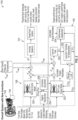
FIG. 2 , an enhancedengine model system 100 is illustrated according to a non-limiting embodiment. The enhancedengine model system 100 includes agas turbine engine 102, one ormore sensor 104, a nominalengine estimation module 106, a self-tunedengine estimation module 108, and a fault detection andisolation module 110. Thegas turbine engine 102 is configured to operate according to one or more engine parameters, the engine parameters including, but not limited to, fuel flow, vane angles, bleed air flow rate, nozzle area, altitude, ambient air pressure, ambient temperature, and throttle lever angle (TLA). The sensors 104 (e.g., a gas path sensor, speed sensors, pressure sensors, temperature sensors, etc.) are configured to monitor operation of the gas turbine engine in real-time and output (e.g., in real-time). Accordingly, one or more of the sensors can output a measured engine parameter signal indicating measured engine parameters (Pmas) of the one or more engine parameters, the measured engine parameters (Pmas) including, but not limited to, engine rotor speeds, engine pressures, and engine temperatures. - The nominal
engine estimation module 106 utilizes one or more on-board engine models (OBEMs) to generate estimated engine parameters representing the measured engine parameters (Pmas). The OBEMs include one or more open-loopnominal engine models 200 and thecalibration adjustment module 206 working in conjunction with theregime recognition module 204 which are described in greater detail below. The openloop engine model 200 represents a manifestation of what is considered nominal and is used as a reference for measuring engine deviation from it due to failure or deterioration. The open-loopnominal engine model 200 is configured to receive the engine parameters and a set of calibration adjustments to generate estimated engine parameters that can be further adjusted by another set of calibration adjustments to generate nominal estimated engine parameters (Pest) representing the measured engine parameters (Pmas). The nominal estimated engine parameters (Pest) can be used as a reference for measuring engine deviation from it, namely, the difference between (Pmas) and (Pest), due to failure or deterioration. - The self-tuning
engine estimation module 108 utilizes one or more on-board engine models (OBEMs) 202 to generate estimated engine parameters representing the measured engine parameters (Pmas) and implements aperformance assessment module 304 to track performance related engine health. The OBEMs include a self-tuned engine model 202 (a.k.a. the closed-loop model), which is closed loop on the adjustments produced by a self-tuningmodule 300 and a long-term deterioration module 302. In addition to the tuning adjustments, the self-tuned closed-loop engine model 202 is configured to receive the engine parameters and a set of calibration adjustments to generate estimated engine parameters that can be further adjusted by another set of calibration adjustment to generate estimated engine parameters (P*est) representing the measured engine parameters (Pmas). - The self-tuned closed-
loop model 202 incorporates the tuning adjustments to parameters in major modules of the engine, e.g., the efficiencies and flow capacities of the compressors and turbines. Instead of being aggregated, the adjustments are divided into two parts to account for engine short-term tuning and long-term deterioration separately. In this manner, the self-tuning capability of theOBEM 202 will be unaffected by the long-term engine deterioration that occurs over time. - The combination of the self-tuning
module 300 and the long-termtrending deterioration module 302 is configured to identify the engine long-term deterioration and separate it from the self-tuning capability. In this manner, the OBEMs can be tuned without influence from the long-term engine deterioration. - The self-tuning
module 300 translates the residuals, namely the difference between (Pmas) and (P*est), to tuning parameters (Δη) which are in turn processed in the long-term deterioration module 302 for extraction of the long-term deterioration (ΔηLT). The long-termtrending deterioration module 302 determines the long-term deterioration tuning parameters (ΔηLT) and outputs them along a first signal path to thePerformance Assessment module 304 to track the engine health based on performance; a second signal path directly to the self-tunedengine model 202 to provide a separate tunning; and a third signal path for ΔηLT to be removed from the aggregated tuning parameters (Δη) to separate the long-term and short-term tuning. The difference, Δη - ΔηLT, is range-limited to prevent unexpected adjustments to theengine model 202, and the results become the short-term tuning parameter (ΔηST), also fed to themodel 202. In this manner, the self-tunedengine estimation module 108 can update the closed-loop self-tunedengine model 202 using the short-term tuning parameters (ΔηsT) independently from the long-term tuning parameters (ΔηLT). For example, the self-tunedengine model 202 is configured to receive both the short-term tuning parameters (ΔηST) and the long-term deterioration (ΔηLT), where the long-term deterioration is incorporated into the base model to result in a model for deteriorated engine while the short-term tuning parameters (ΔηST) are used to tune the self-tunedengine model 202 so that it matches theengine 102 being monitored and controlled. The self-tuningmodule 300 can be implemented as a Kalman Filter, for example, and is configured to determine - tuning parameters (Δη) indicative of the aggregated adjustments to the self-tunedengine model 202 for alignment with theengine 102 based on a difference (ΔP*) between the measured engine parameters (Pmas) and tuned estimated engine parameters (P*est). - According to one or more non-limiting embodiments, the long-
term deterioration module 302 extracts long-term deterioration from (Δη) and compares the identified long-term deterioration against a predefined engine deterioration model implemented in the long-term deterioration module 302 to confirm its validity. The short-term tuning parameters (ΔηST) is determined by removing the confirmed long-term deterioration parameters (ΔηLT) from the aggregated tuning parameters Δη and range-limiting the result. In this manner, the long-term deterioration parameter (ΔηLT) can be excluded from the self-tuning capability so that the short-term tuning parameters (ΔηST) are not saturated by the range limits, and therefore avoid a diminished self-tuning capability found in conventional systems. -
FIG. 4A , for example, is a signal diagram depicting a delta tuner function including long-term engine deterioration parameters (ΔηLT) and capped by parameter limits. To account for engine deterioration over time, delta tuners of conventional Kalman Filters are designed to accommodate the increasing difference between the engine and the model due to all sorts of uncertainties. However, the delta tuners will likely grow out of the limits imposed to prevent the model from getting to some undesired state. When the delta tuners are capped at the limits, the tuning capability will be diminished and the accuracy of the model output (e.g., estimated engine parameters) will be reduced, as shown inFIG. 4A . - As illustrated in
FIG. 4B , however, removing or canceling the long-term deterioration (LTD) from the delta tuner of theKalman Filter 300 as described according one or more non-limiting embodiments of the present disclosure will keep the latter remain within the limits while the self-tuning capability of theKalman Filter 300 is fully retained. In this manner, the long-term deterioration is updated periodically as theengine 102 deteriorates over time while the short-term tuning parameters (ΔηST) are varying continuously in real-time. - According to one or more non-limiting embodiments, the long-term deterioration and the delta tuner with the LTD removed by separation are essentially added back to tune the closed-loop self-tuning
engine model 202. The outcome appears as an unlimited delta tuner being used to adjust the closed-loop self-tuningengine model 202. However, the benefit of separating the LTD from the delta tuner is to allow an additional assessment of LTD being incorporated other than a simple detrend. In one or more non-limiting embodiments, the function of the long-term deterioration trend can be examined with respect to the trend in delta tuner and assess the trend with the prior knowledge of deteriorated engines in the family. The result of this function is the identified long-term engine deterioration for the time period of interest. - Returning to
FIG. 2 , theperformance assessment module 304 is configured to determine a performance change of the gas turbine engine based on the adjusted tuning parameters (Δη) and the long-term deterioration parameters (ΔηLT), and assesses a current performance of theengine 102. The assessed performance can include, but is not limited to, low/high compressor stall margins, Exhaust Gas Temperature (EGT) margins, performance degradation, and Specific Fuel Consumption (SFC). - As described herein, both the
nominal engine model 200 and the self-tunedengine model 202 are calibrated for better alignment with the engine under monitoring and control. According to a non-limiting embodiment, the calibration of both thenominal engine model 200 and the self-tunedengine model 202 is regime-based and completely independent of the self-tuning function. According to a non-limiting embodiment, the different calibration could be applied to thenominal engine model 200 and the self-tunedengine model 202. - The
regime recognition module 204 is configured to determine operating conditions at which theengine 102 is operating. The operating conditions include, for example, the determination of flight phase (e.g., ground idle, taxi-out, takeoff, climb, cruise, descent, approach, landing for a commercial airplane) and operational states (e.g., steady state, quasi-steady state, transient). Based on the current operating conditions, theregime recognition module 204 selects a given calibration model for calibrating the open-loopnominal engine model 200 and the closed-loop self-tuningengine model 202. According to a non-limiting embodiment, theregime recognition module 204 can selected two types of calibration models: an entry into service (EIS) Calibration Model (sometimes referred to as an "Acceptance Calibration Model"); and a Service Calibration Model. - The EIS Calibration Model is constructed based on test cell data from an acceptance test. Module performance is analyzed and converted to residuals compensation using engine performance influence coefficients. Engine installation effects are approximated and accommodated in this model. EIS Calibration Model provides fundamental Engine Model calibration and allows critical FD&I functions at EIS. The FD&I function is restricted to perform in prescribed operating regimes and is limited to detecting flight critical failures with minimal false alerts.
- The Service Calibration Model is constructed based on flight data collected in service. According to a non-limiting embodiment, the regime recognition module can initiate a training mode, which allows collection of training data, for example, Pmas and Pest, and can terminate the training mode when a training condition is met such as, for example, data coverage criteria are met, or a time window expires. According to a non-limiting embodiment, the Service Calibration Models can be trained and managed based on dynamically selected engine operation regimes described in greater detail below.
- According to a non-limiting embodiment, the
regime recognition module 204 performs a progressive learning process that allows the service calibration model to be gradually calibrated so that the performance of the service calibration model can be increasingly improved. For example, every engine will start at EIS with a corresponding model calibrated within a set of prescribed actionable regimes that is previously learned, e.g., during an Acceptance Test Program (ATP). While in service (e.g., during operation of the gas turbine engine 102),regime recognition module 204 will initiate a calibration adjustment mode only when theengine 102 is operating at operating conditions that have not occurred in the past or not previously observed by theregime recognition module 204. Any new model calibrations will then expand the scope of actionable regime associated with the selected calibration model, which allows more data points to be processed by the calibrated models for improved performance. In the case of an engine model that is undergoing calibration, the model-supported FD&I capability, engine parameter estimation, and performance trending will be carried out with the less calibrated model, but they will all be improved over time as the calibration model is calibrated with an ever-growing actionable regime. - According to a non-limiting embodiment, the
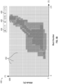
regime recognition module 204 is configured to perform a memory recall function to determine whether or not an operating condition has occurred in the past or has been previously observed. Referring toFIGS. 3A ,3B and3C (collectively referred to asFIGS. 3A-3C ), amemory map 400 utilized by the regime recognition module to perform the memory recall function is illustrated according to a non-limiting embodiment. Thememory map 400 includes a plurality ofcells 402 representing an individual engine operating condition. According to the example shown inFIGS. 3A-3C , each engine operating condition represented by a givencell 402 is defined by an altitude (defined along the Y-axis) at which the engine is operating with respect to a Mach value (defined along the X-axis) at which the engine is operating. It should be appreciated, however, that the X-axis and Y-axis of thememory map 400 can be assigned different variables without departing from the scope of the invention. -
FIG. 3A illustrates thememory map 400 at entry into service (EIS). At this stage, the aircraft has not performed any flights. Therefore, thecells 402 of thememory map 400 are not filled. However, thememory map 400 "grows" as more data is collected during subsequently flights. - Referring to
FIG. 3B , thememory map 400 is illustrated after a first number of flights (e.g., 10 flights). As the aircraft performs subsequent flights, theregime recognition module 204 identifies an engine input parameter set or operating condition among the identified current operating conditions of the aircraft and returns a confidence value indicating the likelihood that this data point has been observed by theregime recognition module 204 during a previous flight. For example, when the confidence value is below a threshold value and/or is a negative value, theregime recognition module 204 can identify or "flag" the engine input parameter set or operating condition(s) as not being previously identified. On the other hand, when the confidence value is above a threshold value and/or is a positive value, theregime recognition module 204 can identify or "flag" the engine input parameter set or operating condition(s) as now being identified or having occurred during operation of thegas turbine engine 102. - According to a non-limiting embodiment, the confidence value can range between -1 and 1, for example, where a higher value indicates a higher confidence that the given engine operating condition has been experienced or previously observed. In this example,
first cells 404 designated with a first shading or first color (e.g., yellow),second cells 406 are designated with a second shading or second color (e.g., blue), andthird cells 408 are designated with a third shading or third color (e.g., green). Thefirst cells 404 are associated with a negative value (e.g., -1) indicating that the corresponding operating condition has likely not been previously observed. Thesecond cells 406 are associated with a second positive value (e.g., 0.5) indicating that the corresponding operating condition has likely been previously observed. Thethird cells 408 are associated with a third positive value (e.g., 1) confirming that the corresponding operating condition has been previously observed. According to a non-limiting embodiment, the third positive value can meet or exceed a threshold value, thereby indicating that its associated operating condition or input parameter set has occurred and has been identified. - Referring to
FIG. 3C , thememory map 400 is illustrated after the aircraft performs an additional number of flights (e.g., 20 flights). As shown inFIG. 3C , one ormore cells 404 corresponding to an operating condition that was previously designated as likely not have been previously observed have now been identified. Accordingly, their corresponding confidence values have been increased and are now designated as likely to have been previously observed (e.g., cells 406) or confirmed to have been previously observed (e.g., cells 408). Similarly, one ormore cells 406 corresponding to an operating condition that was previously designated as likely to have been previously observed have now been identified. Accordingly, their corresponding confidence values have been increased and are now designated confirmed to have been previously observed (e.g., cells 408). In this manner, the calibrated model is improved over time as it is calibrated with an ever-growing actionable regime. - According to a non-limiting embodiment, the memory recall function can be implemented as a neural network trained based on the frequency of clustered input data. The input parameters of the neural network can be assigned to the
cells 402 to form a high dimensional grid defining thememory map 400. Accordingly, the frequency of data points hitting eachcell 402 is normalized to form the confidence target. For repeatable missions or flights such as regular commercial flights, the neural network can train therecognition module 204 using thememory map 400 so that therecognition module 204 learns and remembers previously observed operating conditions sufficiently within a small number of flights, e.g., tens of flights. For less repeatable missions, such as those performed by military aircrafts, for example, thememory map 400 may appear sparser with only concentrated "memories" on common operational phases such as ground idle, takeoff and hover (for rotorcrafts). - Returning to
FIG. 2 , the fault detection andisolation module 110 uses the residual ΔP for fault detection and isolation. According to a non-limiting embodiment, the fault detection andisolation module 110 operates to detect and isolate an engine fault based at least in part on the parameter difference (ΔP) between the measured engine parameters (Pmas) and the estimated nominal engine parameters (Pest). When a fault is detected, the fault detection andisolation module 110 can further operate to identify the particular type of the detected fault. The type of fault detected by the fault detection andisolation module 110 includes, but not limited to, faulty fuel flow, a LPC/HPC variable vane fault, a bleed air leakage, and sensor faults. - Turning to
FIG. 5 , an example of a signal diagram used by the fault detection andisolation module 110 to detect the presence of a fault is illustrated according to a non-limiting embodiment. The fault detection andisolation module 110 inputs a signal indicative of the engine parameter difference (ΔP) and continuously monitors it over a period of time. While the fault detection andisolation module 110 monitors the engine parameter difference (ΔP), a discrete event may occur during which parameter difference (ΔP) abruptly increases. When the increased parameter difference (ΔP) exceeds a differential threshold (ΔPTH), the fault detection andisolation module 110 determines the presence of a fault and will move to isolate origin of the fault and/or identify the type of fault. - With reference now to
FIG. 6 , a method of using and training a service calibration model is illustrated according to a non-limiting embodiment. The method begins atoperation 900 and atoperation 902 determination is performed as to whether any calibrated service models is available. When one or more calibrated service models are available, the method proceeds tooperation 922 to determine if the regime is recognizable, namely, if the engine operating condition has been experienced or previously observed. If the regime is recognized, the method proceeds to 904 to call the available calibrated service models for use. Atoperation 906, the Fault Detection and Isolation (FD&I) function is applied to the selected service calibration model. Atoperation 908, the full functional performance monitoring is conducted with the selected service calibration model, and the method ends atoperation 912. - When, however, one or more calibrated service models are not available at
operation 902, the method proceeds tooperation 914 and limits the selected EIS calibration model to prescribed operational regimes. Atoperation 918, a Fault Detection and Isolation (FD&I) function is applied to the selected EIS calibration model. Atoperation 920, the performance trending of the selected EIS calibration model placed on hold or "paused" and the method ends atoperation 912. - In addition, when one or more calibrated service models are available at
operation 902, but the regime is not recognizable atoperation 922, the method proceeds tooperation 924 to call for use of previously calibrated service model and perform FD&I as well as performance trending atoperation 926. In this case, one or more service calibration models require training, and the training mode is initiated atoperation 928 upon completion of the flight. The service models are trained, and the memory map corresponding to the service calibration model is updated atoperation 930. The method ends atoperation 912. - As described herein one or more non-limiting embodiments of the disclosure provide a self-calibrating dynamic model that can be used upon engine EIS and calibrated only when needed. The self-calibrating dynamic model can perform calibration of a nominal and self-tuning engine models as they are used for FD&I and performance assessment. The self-calibrating dynamic model also can separate the long-term tuning parameters and the short-term tuning parameters from one another so that the self-tuning capability is not compromised or diminished as the engine deteriorates.
- The term "about" is intended to include the degree of error associated with measurement of the particular quantity based upon the equipment available at the time of filing the application. For example, "about" can include a range of ± 8% or 5%, or 2% of a given value.
- The terminology used herein is for the purpose of describing particular embodiments only and is not intended to be limiting of the present disclosure. As used herein, the singular forms "a", "an" and "the" are intended to include the plural forms as well, unless the context clearly indicates otherwise. It will be further understood that the terms "comprises" and/or "comprising," when used in this specification, specify the presence of stated features, integers, steps, operations, elements, and/or components, but do not preclude the presence or addition of one or more other features, integers, steps, operations, element components, and/or groups thereof.
- While the present disclosure has been described with reference to an exemplary embodiment or embodiments, it will be understood by those skilled in the art that various changes may be made, and equivalents may be substituted for elements thereof without departing from the scope of the present disclosure. In addition, many modifications may be made to adapt a particular situation or material to the teachings of the present disclosure without departing from the essential scope thereof. Therefore, it is intended that the present disclosure is not limited to the particular embodiment disclosed as the best mode contemplated for carrying out this present disclosure, but that the present disclosure will include all embodiments falling within the scope of the claims.
Claims (15)
- An engine model calibration system (100) comprising:a gas turbine engine (102) configured to operate according to one or more engine operating parameters;a sensor (104) configured to monitor the gas turbine engine (102) and output measured parameters (Pmas) indicative of the one or more engine operating parameters; anda nominal engine estimation module (106) including an open-loop nominal engine model (200) configured to output estimated nominal engine parameters (Pest) indicative of the one or more engine operating parameters, wherein the nominal engine estimation module (106) identifies one or more engine operating conditions of the gas turbine engine (102) based on the one or more engine operating parameters and selectively updates the open-loop nominal engine model (200) based on the identified one or more engine operating conditions.
- The engine model calibration system (100) of claim 1, further comprising a self-tuned engine estimation module (108) including a closed-loop self-tuned engine model (202) configured to output estimated self-tuned engine parameters (P*est) indicative of the one or more engine operating parameters, wherein the self-tuned engine estimation module (108) updates the closed-loop self-tuned engine model (202) based on short-term tuning parameters (ΔηST) and long-term tuning parameters (ΔηLT).
- The engine model calibration system (100) of claim 2, wherein the self-tuned engine estimation module (108) further comprises:a self-tuning module (300) configured to determine adjusted tuning parameters (Δη) indicative of aggregated adjustments to the closed-loop self-tuned engine model (202) based a difference between the measured parameters (Pmas) and the estimated self-tuned engine parameters (P*est); anda long-term trending deterioration module (302) configured to determine the long-term tuning parameters (ΔηLT) based on the adjusted tuning parameters (Δη) and to determine the short-term tuning parameters (ΔηST) based on a difference between the adjusted tuning parameters (Δη) and the long-term tuning parameters (ΔηLT).
- The engine model calibration system (100) of claim 2 or 3, wherein the self-tuned engine estimation module (108) updates the closed-loop self-tuned engine model (202) using the short-term tuning parameters (ΔηST) independently from the long-term tuning parameters (ΔηLT).
- The engine model calibration system (100) of any preceding claim, wherein the nominal engine estimation module (106) further comprises:a regime recognition module (204) that identifies the engine operating conditions; anda calibration adjustment module (206) configured to selectively update the open-loop nominal engine model (200) and the closed-loop self-tuned engine model (202) based on the one or more engine operating conditions identified by the regime recognition module (204).
- The engine model calibration system (100) of claim 5, wherein the regime recognition module (204) selects a given calibration model among a plurality of different calibration models based on the identified one or more engine operating conditions, and delivers the selected calibration model to the calibration adjustment module (206), and the calibration adjustment module (206) updates the open-loop nominal engine model (200) and the closed-loop self-tuned engine model (202) based on the selected calibration model, optionally wherein:
the plurality of different calibration models include an entry into service model that is constructed based on test cell data generated according to an acceptance test, and a service calibration model that is constructed based on flight data collected during operation of the gas turbine engine (102). - The engine model calibration system (100) of claim 6, wherein the regime recognition module (204) initiates a calibration adjustment mode to calibrate the open-loop nominal engine model (200) and the closed-loop self-tuned engine model (202) in response to determining that the identified one or more engine operating conditions were not previously identified.
- The engine model calibration system (100) of claim 7, wherein the regime recognition module (204) assigns confidence values to the operating conditions of the gas turbine engine (102) and determines when the identified one or more engine operating conditions were not previously identified based the confidence values and a threshold value, optionally wherein:
in response to initiating the calibration mode, the regime recognition module (204) increases the confidence value of the identified operating conditions. - A method of calibrating an engine model representing a gas turbine engine (102) configured to operate according to one or more engine operating parameters, the method comprising:monitoring, via a sensor (104), the gas turbine engine (102) and outputting from the sensor (104) measured parameters (Pmas) indicative of the one or more engine operating parameters;outputting, via a nominal engine estimation module (106) including an open-loop nominal engine model (200), estimated nominal engine parameters (Pest) indicative of the one or more engine operating parameters;identifying, via the nominal engine estimation module (106), one or more engine operating conditions of the gas turbine engine (102) based on the one or more engine operating parameters; andselectively updating the open-loop nominal engine model (200) based on the identified one or more engine operating conditions.
- The method of claim 9, further comprising:outputting, via a self-tuned engine estimation module (108) including a closed-loop self-tuned engine model (202), estimated self-tuned engine parameters (P*est) indicative of the one or more engine operating parameters; andupdating the closed-loop self-tuned engine model (202) based on short-term tuning parameters (ΔηST) and long-term tuning parameters (ΔηLT).
- The method of claim 10, further comprising:determining, via a self-tuning module (300), adjusted tuning parameters (Δη) indicative of aggregated adjustments to the closed-loop self-tuned engine model (202) based on a difference between the measured parameters (Pmas) and the estimated self-tuned engine parameters (P*est);determining, via a long-term trending deterioration module (302), the long-term tuning parameters (ΔηLT) based on the adjusted tuning parameters (Δη); anddetermining the short-term tuning parameters (ΔηST) based on a difference between the adjusted tuning parameters (Δη) and the long-term tuning parameters (ΔηLT).
- The method of claim 10 or 11, wherein the self-tuned engine estimation module (108) updates the closed-loop self-tuned engine model (202) using the short-term tuning parameters (ΔηST) independently from the long-term tuning parameters (ΔηLT).
- The method of any of claims 9 to 12, further comprising:identifying, via a regime recognition module (204), the engine operating conditions; andselectively updating the open-loop nominal engine model (200) and the closed-loop self-tuned engine model (202) using a calibration adjustment model based on the one or more engine operating conditions identified by the regime recognition module (204).
- The method of claim 13, further comprising:selecting, via the regime recognition module (204), a given calibration model among a plurality of different calibration models based on the identified one or more engine operating conditions;delivering the selected calibration model to a calibration adjustment module (206); andupdating, via the calibration adjustment module (206), the open-loop nominal engine model (200) and the closed-loop self-tuned engine model (202) based on the selected calibration model, optionally wherein:
the plurality of different calibration models includes an entry into service model that is constructed based on test cell data generated according to an acceptance test, and a service calibration model that is constructed based on flight data collected during operation of the gas turbine engine (102). - The method of claim 14, further comprising initiating, via the regime recognition module (204), a calibration adjustment mode to calibrate the open-loop nominal engine model (200) and the closed-loop self-tuned engine model (202) in response to determining that the identified one or more engine operating conditions were not previously identified, optionally wherein the method further comprises:assigning, via the regime recognition module (204), confidence values to the operating conditions of the gas turbine engine (102); anddetermining, via the regime recognition module (204), when the identified one or more engine operating conditions were not previously identified based the confidence values and a threshold value, optionally wherein:
in response to initiating the calibration mode, the regime recognition module (204) increases the confidence value of the identified operating conditions.
Applications Claiming Priority (1)
| Application Number | Priority Date | Filing Date | Title |
|---|---|---|---|
| US18/151,939 US20240229724A1 (en) | 2023-01-09 | 2023-01-09 | Enhanced engine model for control and health monitoring |
Publications (2)
| Publication Number | Publication Date |
|---|---|
| EP4398055A1 true EP4398055A1 (en) | 2024-07-10 |
| EP4398055B1 EP4398055B1 (en) | 2025-11-05 |
Family
ID=89542259
Family Applications (1)
| Application Number | Title | Priority Date | Filing Date |
|---|---|---|---|
| EP24151034.6A Active EP4398055B1 (en) | 2023-01-09 | 2024-01-09 | Enhanced engine model for control and health monitoring |
Country Status (2)
| Country | Link |
|---|---|
| US (1) | US20240229724A1 (en) |
| EP (1) | EP4398055B1 (en) |
Citations (3)
| Publication number | Priority date | Publication date | Assignee | Title |
|---|---|---|---|---|
| US20070073525A1 (en) * | 2005-09-27 | 2007-03-29 | General Electric Company | Method and system for gas turbine engine simulation using adaptive Kalman filter |
| US20170146976A1 (en) * | 2015-11-25 | 2017-05-25 | United Technologies Corporation | Fault detection methods and systems |
| EP3690559A1 (en) * | 2019-02-01 | 2020-08-05 | United Technologies Corporation | Machine learned aero-thermodynamic engine inlet condition synthesis |
Family Cites Families (4)
| Publication number | Priority date | Publication date | Assignee | Title |
|---|---|---|---|---|
| US7233884B2 (en) * | 2002-10-31 | 2007-06-19 | United Technologies Corporation | Methodology for temporal fault event isolation and identification |
| US20140088766A1 (en) * | 2012-09-21 | 2014-03-27 | United Technologies Corporation | Health management having system level diagnostic feedback and information fusion |
| US20170370790A1 (en) * | 2015-02-04 | 2017-12-28 | Sikorsky Aircraft Corporation | Estimating dynamic thrust or shaft power of an engine |
| US10822996B2 (en) * | 2018-03-12 | 2020-11-03 | General Electric Company | Gas turbine engine health determination |
-
2023
- 2023-01-09 US US18/151,939 patent/US20240229724A1/en active Pending
-
2024
- 2024-01-09 EP EP24151034.6A patent/EP4398055B1/en active Active
Patent Citations (3)
| Publication number | Priority date | Publication date | Assignee | Title |
|---|---|---|---|---|
| US20070073525A1 (en) * | 2005-09-27 | 2007-03-29 | General Electric Company | Method and system for gas turbine engine simulation using adaptive Kalman filter |
| US20170146976A1 (en) * | 2015-11-25 | 2017-05-25 | United Technologies Corporation | Fault detection methods and systems |
| EP3690559A1 (en) * | 2019-02-01 | 2020-08-05 | United Technologies Corporation | Machine learned aero-thermodynamic engine inlet condition synthesis |
Non-Patent Citations (1)
| Title |
|---|
| FENG LU ET AL: "A Model-Based Approach for Gas Turbine Engine Performance Optimal Estimation", ASIAN JOURNAL OF CONTROL, CHINESE AUTOMATIC CONTROL SOCIETY, HOBOKEN, USA, vol. 15, no. 6, 20 June 2013 (2013-06-20), pages 1794 - 1808, XP072341367, ISSN: 1561-8625, DOI: 10.1002/ASJC.737 * |
Also Published As
| Publication number | Publication date |
|---|---|
| EP4398055B1 (en) | 2025-11-05 |
| US20240229724A1 (en) | 2024-07-11 |
Similar Documents
| Publication | Publication Date | Title |
|---|---|---|
| US20250320832A1 (en) | Machine learned aero-thermodynamic engine inlet condition synthesis | |
| Kobayashi et al. | Application of a bank of Kalman filters for aircraft engine fault diagnostics | |
| US7020595B1 (en) | Methods and apparatus for model based diagnostics | |
| US10423473B2 (en) | Fault-accommodating, constrained model-based control using on-board methods for detection of and adaption to actuation subsystem faults | |
| US7861578B2 (en) | Methods and systems for estimating operating parameters of an engine | |
| US6502085B1 (en) | Methods and systems for estimating engine faults | |
| Simon et al. | A model-based anomaly detection approach for analyzing streaming aircraft engine measurement data | |
| EP2770390B1 (en) | System and method for continuous performance analysis of systems that exhibit variable performance characteristics at different operating conditions | |
| EP3607189B1 (en) | Method and system for adjusting an operating parameter as a function of component health | |
| FR2883330A1 (en) | SYSTEM AND METHOD FOR SPECIFIC SYSTEM ANALYSIS OF A TURBOMACHINE | |
| US10551818B2 (en) | Fault detection methods and systems | |
| Kobayashi et al. | Evaluation of an enhanced bank of Kalman filters for in-flight aircraft engine sensor fault diagnostics | |
| US20170030217A1 (en) | Use of ss data trends in fault resolution process | |
| EP3712737B1 (en) | Signal response monitoring for turbine engines | |
| US20240229724A1 (en) | Enhanced engine model for control and health monitoring | |
| US20170074173A1 (en) | Control system and method of controlling a variable area gas turbine engine | |
| EP4372210A1 (en) | Tuning engine parameter estimator using gas path analysis data | |
| Kobayashi et al. | Aircraft engine on-line diagnostics through dual-channel sensor measurements: Development of a baseline system | |
| Viassolo et al. | Advanced estimation for aircraft engines | |
| WO2025014873A1 (en) | Defect detection in aircraft engines using visual neuromorphic sensors | |
| EP3064744B1 (en) | Diagnosis of gas turbine aircraft engines | |
| EP4332708A1 (en) | Engine control system and method with artificial intelligence sensor training | |
| US20250012672A1 (en) | Aircraft engine inlet monitoring using neuromorphic sensors | |
| US20250012670A1 (en) | Aircraft engine data acquisition using thermal neuromorphic sensors | |
| US20250011004A1 (en) | Data acquisiton for aircraft engines using neuromorphic sensors |
Legal Events
| Date | Code | Title | Description |
|---|---|---|---|
| PUAI | Public reference made under article 153(3) epc to a published international application that has entered the european phase |
Free format text: ORIGINAL CODE: 0009012 |
|
| STAA | Information on the status of an ep patent application or granted ep patent |
Free format text: STATUS: THE APPLICATION HAS BEEN PUBLISHED |
|
| AK | Designated contracting states |
Kind code of ref document: A1 Designated state(s): AL AT BE BG CH CY CZ DE DK EE ES FI FR GB GR HR HU IE IS IT LI LT LU LV MC ME MK MT NL NO PL PT RO RS SE SI SK SM TR |
|
| STAA | Information on the status of an ep patent application or granted ep patent |
Free format text: STATUS: REQUEST FOR EXAMINATION WAS MADE |
|
| 17P | Request for examination filed |
Effective date: 20250110 |
|
| GRAP | Despatch of communication of intention to grant a patent |
Free format text: ORIGINAL CODE: EPIDOSNIGR1 |
|
| STAA | Information on the status of an ep patent application or granted ep patent |
Free format text: STATUS: GRANT OF PATENT IS INTENDED |
|
| INTG | Intention to grant announced |
Effective date: 20250526 |
|
| GRAS | Grant fee paid |
Free format text: ORIGINAL CODE: EPIDOSNIGR3 |
|
| GRAA | (expected) grant |
Free format text: ORIGINAL CODE: 0009210 |
|
| STAA | Information on the status of an ep patent application or granted ep patent |
Free format text: STATUS: THE PATENT HAS BEEN GRANTED |
|
| AK | Designated contracting states |
Kind code of ref document: B1 Designated state(s): AL AT BE BG CH CY CZ DE DK EE ES FI FR GB GR HR HU IE IS IT LI LT LU LV MC ME MK MT NL NO PL PT RO RS SE SI SK SM TR |
|
| REG | Reference to a national code |
Ref country code: CH Ref legal event code: F10 Free format text: ST27 STATUS EVENT CODE: U-0-0-F10-F00 (AS PROVIDED BY THE NATIONAL OFFICE) Effective date: 20251105 Ref country code: GB Ref legal event code: FG4D |
|
| REG | Reference to a national code |
Ref country code: DE Ref legal event code: R096 Ref document number: 602024001106 Country of ref document: DE |
|
| REG | Reference to a national code |
Ref country code: IE Ref legal event code: FG4D |
|
| PGFP | Annual fee paid to national office [announced via postgrant information from national office to epo] |
Ref country code: FR Payment date: 20251217 Year of fee payment: 3 |
|
| REG | Reference to a national code |
Ref country code: NL Ref legal event code: MP Effective date: 20251105 |
|
| PG25 | Lapsed in a contracting state [announced via postgrant information from national office to epo] |
Ref country code: ES Free format text: LAPSE BECAUSE OF FAILURE TO SUBMIT A TRANSLATION OF THE DESCRIPTION OR TO PAY THE FEE WITHIN THE PRESCRIBED TIME-LIMIT Effective date: 20251105 |
|
| REG | Reference to a national code |
Ref country code: LT Ref legal event code: MG9D |
|
| PG25 | Lapsed in a contracting state [announced via postgrant information from national office to epo] |
Ref country code: NO Free format text: LAPSE BECAUSE OF FAILURE TO SUBMIT A TRANSLATION OF THE DESCRIPTION OR TO PAY THE FEE WITHIN THE PRESCRIBED TIME-LIMIT Effective date: 20260205 |
|
| PGFP | Annual fee paid to national office [announced via postgrant information from national office to epo] |
Ref country code: DE Payment date: 20251217 Year of fee payment: 3 |
|
| PG25 | Lapsed in a contracting state [announced via postgrant information from national office to epo] |
Ref country code: FI Free format text: LAPSE BECAUSE OF FAILURE TO SUBMIT A TRANSLATION OF THE DESCRIPTION OR TO PAY THE FEE WITHIN THE PRESCRIBED TIME-LIMIT Effective date: 20251105 Ref country code: HR Free format text: LAPSE BECAUSE OF FAILURE TO SUBMIT A TRANSLATION OF THE DESCRIPTION OR TO PAY THE FEE WITHIN THE PRESCRIBED TIME-LIMIT Effective date: 20251105 Ref country code: AT Free format text: LAPSE BECAUSE OF FAILURE TO SUBMIT A TRANSLATION OF THE DESCRIPTION OR TO PAY THE FEE WITHIN THE PRESCRIBED TIME-LIMIT Effective date: 20251105 |
|
| PGFP | Annual fee paid to national office [announced via postgrant information from national office to epo] |
Ref country code: AT Payment date: 20260301 Year of fee payment: 3 |
|
| REG | Reference to a national code |
Ref country code: AT Ref legal event code: MK05 Ref document number: 1855024 Country of ref document: AT Kind code of ref document: T Effective date: 20251105 |
|
| PG25 | Lapsed in a contracting state [announced via postgrant information from national office to epo] |
Ref country code: NL Free format text: LAPSE BECAUSE OF FAILURE TO SUBMIT A TRANSLATION OF THE DESCRIPTION OR TO PAY THE FEE WITHIN THE PRESCRIBED TIME-LIMIT Effective date: 20251105 |
|
| PG25 | Lapsed in a contracting state [announced via postgrant information from national office to epo] |
Ref country code: RS Free format text: LAPSE BECAUSE OF FAILURE TO SUBMIT A TRANSLATION OF THE DESCRIPTION OR TO PAY THE FEE WITHIN THE PRESCRIBED TIME-LIMIT Effective date: 20260205 |
|
| PG25 | Lapsed in a contracting state [announced via postgrant information from national office to epo] |
Ref country code: IS Free format text: LAPSE BECAUSE OF FAILURE TO SUBMIT A TRANSLATION OF THE DESCRIPTION OR TO PAY THE FEE WITHIN THE PRESCRIBED TIME-LIMIT Effective date: 20260305 |
|
| PG25 | Lapsed in a contracting state [announced via postgrant information from national office to epo] |
Ref country code: PT Free format text: LAPSE BECAUSE OF FAILURE TO SUBMIT A TRANSLATION OF THE DESCRIPTION OR TO PAY THE FEE WITHIN THE PRESCRIBED TIME-LIMIT Effective date: 20260305 |
|
| PG25 | Lapsed in a contracting state [announced via postgrant information from national office to epo] |
Ref country code: PL Free format text: LAPSE BECAUSE OF FAILURE TO SUBMIT A TRANSLATION OF THE DESCRIPTION OR TO PAY THE FEE WITHIN THE PRESCRIBED TIME-LIMIT Effective date: 20251105 |
|
| PG25 | Lapsed in a contracting state [announced via postgrant information from national office to epo] |
Ref country code: LV Free format text: LAPSE BECAUSE OF FAILURE TO SUBMIT A TRANSLATION OF THE DESCRIPTION OR TO PAY THE FEE WITHIN THE PRESCRIBED TIME-LIMIT Effective date: 20251105 |
|
| PG25 | Lapsed in a contracting state [announced via postgrant information from national office to epo] |
Ref country code: BG Free format text: LAPSE BECAUSE OF FAILURE TO SUBMIT A TRANSLATION OF THE DESCRIPTION OR TO PAY THE FEE WITHIN THE PRESCRIBED TIME-LIMIT Effective date: 20251105 |