EP4398038A1 - Recycling treatment device, washing-out device, and method for manufacturing flexographic printing plate - Google Patents
Recycling treatment device, washing-out device, and method for manufacturing flexographic printing plate Download PDFInfo
- Publication number
- EP4398038A1 EP4398038A1 EP22864331.8A EP22864331A EP4398038A1 EP 4398038 A1 EP4398038 A1 EP 4398038A1 EP 22864331 A EP22864331 A EP 22864331A EP 4398038 A1 EP4398038 A1 EP 4398038A1
- Authority
- EP
- European Patent Office
- Prior art keywords
- printing plate
- flexographic printing
- plate precursor
- washing solution
- resin aggregate
- Prior art date
- Legal status (The legal status is an assumption and is not a legal conclusion. Google has not performed a legal analysis and makes no representation as to the accuracy of the status listed.)
- Pending
Links
Images






Classifications
-
- B—PERFORMING OPERATIONS; TRANSPORTING
- B01—PHYSICAL OR CHEMICAL PROCESSES OR APPARATUS IN GENERAL
- B01D—SEPARATION
- B01D21/00—Separation of suspended solid particles from liquids by sedimentation
- B01D21/26—Separation of sediment aided by centrifugal force or centripetal force
- B01D21/262—Separation of sediment aided by centrifugal force or centripetal force by using a centrifuge
-
- B—PERFORMING OPERATIONS; TRANSPORTING
- B41—PRINTING; LINING MACHINES; TYPEWRITERS; STAMPS
- B41C—PROCESSES FOR THE MANUFACTURE OR REPRODUCTION OF PRINTING SURFACES
- B41C1/00—Forme preparation
- B41C1/18—Curved printing formes or printing cylinders
-
- C—CHEMISTRY; METALLURGY
- C02—TREATMENT OF WATER, WASTE WATER, SEWAGE, OR SLUDGE
- C02F—TREATMENT OF WATER, WASTE WATER, SEWAGE, OR SLUDGE
- C02F1/00—Treatment of water, waste water, or sewage
- C02F1/38—Treatment of water, waste water, or sewage by centrifugal separation
- C02F1/385—Treatment of water, waste water, or sewage by centrifugal separation by centrifuging suspensions
-
- G—PHYSICS
- G03—PHOTOGRAPHY; CINEMATOGRAPHY; ANALOGOUS TECHNIQUES USING WAVES OTHER THAN OPTICAL WAVES; ELECTROGRAPHY; HOLOGRAPHY
- G03F—PHOTOMECHANICAL PRODUCTION OF TEXTURED OR PATTERNED SURFACES, e.g. FOR PRINTING, FOR PROCESSING OF SEMICONDUCTOR DEVICES; MATERIALS THEREFOR; ORIGINALS THEREFOR; APPARATUS SPECIALLY ADAPTED THEREFOR
- G03F7/00—Photomechanical, e.g. photolithographic, production of textured or patterned surfaces, e.g. printing surfaces; Materials therefor, e.g. comprising photoresists; Apparatus specially adapted therefor
- G03F7/004—Photosensitive materials
- G03F7/038—Macromolecular compounds which are rendered insoluble or differentially wettable
-
- G—PHYSICS
- G03—PHOTOGRAPHY; CINEMATOGRAPHY; ANALOGOUS TECHNIQUES USING WAVES OTHER THAN OPTICAL WAVES; ELECTROGRAPHY; HOLOGRAPHY
- G03F—PHOTOMECHANICAL PRODUCTION OF TEXTURED OR PATTERNED SURFACES, e.g. FOR PRINTING, FOR PROCESSING OF SEMICONDUCTOR DEVICES; MATERIALS THEREFOR; ORIGINALS THEREFOR; APPARATUS SPECIALLY ADAPTED THEREFOR
- G03F7/00—Photomechanical, e.g. photolithographic, production of textured or patterned surfaces, e.g. printing surfaces; Materials therefor, e.g. comprising photoresists; Apparatus specially adapted therefor
- G03F7/26—Processing photosensitive materials; Apparatus therefor
- G03F7/30—Imagewise removal using liquid means
- G03F7/3035—Imagewise removal using liquid means from printing plates fixed on a cylinder or on a curved surface; from printing cylinders
-
- G—PHYSICS
- G03—PHOTOGRAPHY; CINEMATOGRAPHY; ANALOGOUS TECHNIQUES USING WAVES OTHER THAN OPTICAL WAVES; ELECTROGRAPHY; HOLOGRAPHY
- G03F—PHOTOMECHANICAL PRODUCTION OF TEXTURED OR PATTERNED SURFACES, e.g. FOR PRINTING, FOR PROCESSING OF SEMICONDUCTOR DEVICES; MATERIALS THEREFOR; ORIGINALS THEREFOR; APPARATUS SPECIALLY ADAPTED THEREFOR
- G03F7/00—Photomechanical, e.g. photolithographic, production of textured or patterned surfaces, e.g. printing surfaces; Materials therefor, e.g. comprising photoresists; Apparatus specially adapted therefor
- G03F7/26—Processing photosensitive materials; Apparatus therefor
- G03F7/30—Imagewise removal using liquid means
- G03F7/3042—Imagewise removal using liquid means from printing plates transported horizontally through the processing stations
- G03F7/3057—Imagewise removal using liquid means from printing plates transported horizontally through the processing stations characterised by the processing units other than the developing unit, e.g. washing units
-
- G—PHYSICS
- G03—PHOTOGRAPHY; CINEMATOGRAPHY; ANALOGOUS TECHNIQUES USING WAVES OTHER THAN OPTICAL WAVES; ELECTROGRAPHY; HOLOGRAPHY
- G03F—PHOTOMECHANICAL PRODUCTION OF TEXTURED OR PATTERNED SURFACES, e.g. FOR PRINTING, FOR PROCESSING OF SEMICONDUCTOR DEVICES; MATERIALS THEREFOR; ORIGINALS THEREFOR; APPARATUS SPECIALLY ADAPTED THEREFOR
- G03F7/00—Photomechanical, e.g. photolithographic, production of textured or patterned surfaces, e.g. printing surfaces; Materials therefor, e.g. comprising photoresists; Apparatus specially adapted therefor
- G03F7/26—Processing photosensitive materials; Apparatus therefor
- G03F7/30—Imagewise removal using liquid means
- G03F7/3092—Recovery of material; Waste processing
-
- G—PHYSICS
- G03—PHOTOGRAPHY; CINEMATOGRAPHY; ANALOGOUS TECHNIQUES USING WAVES OTHER THAN OPTICAL WAVES; ELECTROGRAPHY; HOLOGRAPHY
- G03F—PHOTOMECHANICAL PRODUCTION OF TEXTURED OR PATTERNED SURFACES, e.g. FOR PRINTING, FOR PROCESSING OF SEMICONDUCTOR DEVICES; MATERIALS THEREFOR; ORIGINALS THEREFOR; APPARATUS SPECIALLY ADAPTED THEREFOR
- G03F7/00—Photomechanical, e.g. photolithographic, production of textured or patterned surfaces, e.g. printing surfaces; Materials therefor, e.g. comprising photoresists; Apparatus specially adapted therefor
- G03F7/26—Processing photosensitive materials; Apparatus therefor
- G03F7/30—Imagewise removal using liquid means
- G03F7/32—Liquid compositions therefor, e.g. developers
- G03F7/322—Aqueous alkaline compositions
-
- C—CHEMISTRY; METALLURGY
- C02—TREATMENT OF WATER, WASTE WATER, SEWAGE, OR SLUDGE
- C02F—TREATMENT OF WATER, WASTE WATER, SEWAGE, OR SLUDGE
- C02F2103/00—Nature of the water, waste water, sewage or sludge to be treated
- C02F2103/34—Nature of the water, waste water, sewage or sludge to be treated from industrial activities not provided for in groups C02F2103/12 - C02F2103/32
Definitions
- the filter unit has a solid substance collector that is disposed to be rotatable and that is arranged such that the solid substances are deposited during rotation.
- the collector is provided to be removable from the filter unit while maintaining a relationship between the collector and the solid substances deposited thereon.
- a non-exposed portion is removed, and solid contents are dispersed in the washing solution as the non-exposed portion is removed.
- a resin aggregate is generated. Since the resin aggregate is fixed to an inner wall of a developing tank, particularly near a gas-liquid interface with the washing solution of the developing tank, it is necessary to periodically clean the developing tank in order to remove the resin aggregate.
- the solid contents described above are the same as the solid substances of JP1994-504230A ( JP-H6-504230A ).
- JP1994-504230A JP-H6-504230A
- the solid substances are separated out in combination of the centrifugation and the filter unit. Even in a state where the solid substances are filtered out by the filter unit, in a case where the amount of a filtrate increases, a large amount of solid substances pass through the inside of a pipe through which the filtrate passes, the solid substances aggregate in the pipe, and a resin aggregate is generated. In this case, as in the developing tank described above, it is also necessary to periodically clean the pipe, such as removing the resin aggregate or the like. In a case where cleaning frequency increases, a work load caused by cleaning increases.
- a regeneration treatment apparatus that from a used washing solution containing a resin aggregate generated as a non-exposed portion of an imagewise exposed flexographic printing plate precursor having a photosensitive resin layer is removed through development using a washing solution of which a main component is water, removes the resin aggregate
- the regeneration treatment apparatus comprising a centrifuge that has a rotating body for separating out the resin aggregate from the used washing solution and an induction path through which the resin aggregate from the centrifuge passes, in which a portion in contact with the resin aggregate has a critical surface tension of 31 mN/m or less and a dynamic friction coefficient of 0.2 or less.
- the portion in contact with the resin aggregate is the induction path.
- the portion in contact with the resin aggregate is composed of at least one selected from groups consisting of perfluoroalkoxy alkane, polytetrafluoroethylene, and polyethylene having an average molecular weight of 700,000 or more.
- a regeneration treatment apparatus that from a used washing solution containing a resin aggregate generated as a non-exposed portion of an imagewise exposed flexographic printing plate precursor having a photosensitive resin layer is removed through development using a washing solution of which a main component is water, removes the resin aggregate, in which a portion in contact with the resin aggregate is composed of polyethylene having an average molecular weight of 750,000 to 6,000,000.
- the portion in contact with the resin aggregate is a portion in contact with the resin aggregate once or repeatedly.
- a washout processor comprising the regeneration treatment apparatus.
- a washout processor that develops an imagewise exposed flexographic printing plate precursor having a photosensitive resin layer using a washing solution of which a main component is water, in which a portion in contact with a used washing solution which contains a resin aggregate generated as a non-exposed portion of the imagewise exposed flexographic printing plate precursor is removed has a critical surface tension of 31 mN/m or less and a dynamic friction coefficient of 0.2 or less.
- a portion in contact with the resin aggregate is composed of at least one selected from groups consisting of perfluoroalkoxy alkane, polytetrafluoroethylene, and polyethylene having an average molecular weight of 700,000 or more.
- a portion in contact with the resin aggregate is composed of at least one selected from groups consisting of polyethylene having an average molecular weight of 750,000 to 6,000,000.
- a portion in contact with the resin aggregate is a portion in contact with the resin aggregate once or repeatedly.
- the regeneration treatment apparatus it is possible to provide the regeneration treatment apparatus, the washout processor, and the manufacturing method of a flexographic printing plate in which attachment of the resin aggregate generated as the non-exposed portion of the imagewise exposed flexographic printing plate precursor having the photosensitive resin layer is removed through development using the washing solution can be suppressed and the resin aggregate can be easily cleaned off even in a case of being attached.
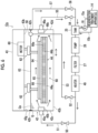
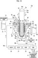
- the washout processor 12 is an apparatus that develops an imagewise exposed flexographic printing plate precursor 32 having a photosensitive resin layer (not shown) using a washing solution of which a main component is water.
- the pipe 21 is provided at a lower surface 20b of the developing tank 20.
- the tank 25 is connected to the pipe 21.
- a pump 26 and a filter 27 are provided at the tank 25 in this order.
- the developing brush 22 is rotated about a rotation shaft 22c by a driving unit (not shown).
- the washing solution Q or a regenerated washing solution is supplied to the developing brush 22 via the rotation shaft 22c.
- the washing solution Q or the regenerated washing solution is supplied from the developing brush 22 to a plate surface 32a of the flexographic printing plate precursor 32.
- the developing brush 22 is not limited to being rotationally moved and may perform a combination of linear reciprocation and circular movement.
- the developing brush 22 is not limited to one, and for example, a plurality of developing brushes may be disposed.
- the rinsing unit 24 may be configured to have a liquid drain nozzle (not shown) that removes the rinsing liquid supplied to the flexographic printing plate precursor 32 by jetting a gas or that removes the rinsing liquid by sucking a gas.
- the tank 25 stores a used washing solution containing a resin aggregate after development and stores a used washing solution from which a resin aggregate is removed by the regeneration treatment apparatus 14, that is, a regenerated washing solution.
- the imagewise exposed flexographic printing plate precursor 32 is developed in the developing tank 20.
- the developing brush 22 is disposed on an opening 20a side in the developing tank 20.
- a support plate 30 is provided to face the developing brush 22.
- the flexographic printing plate precursor 32 may be developed in a state of being immersed in the washing solution Q in the developing tank 20 or may be developed while the washing solution Q is supplied to the flexographic printing plate precursor 32.
- the imagewise exposed flexographic printing plate precursor 32 is disposed at the support plate 30.
- the flexographic printing plate precursor 32 is, for example, quadrangular in plan view.
- the flexographic printing plate precursor 32 is linearly reciprocated in a direction Dw by a moving mechanism (not shown). For example, the flexographic printing plate precursor is moved below the developing brush 22, is developed, and is moved to an opposite side of the developing brush 22 after development. In this case, residues on the plate surface 32a of the flexographic printing plate precursor 32 are removed by the rinsing unit 24.
- the moving mechanism can also adjust the speed of linear reciprocation of the flexographic printing plate precursor 32, that is, a moving speed in the direction Dw.
- the moving speed in the direction Dw described above, a set distance described above, a total reciprocating distance, the number of times of reciprocation in linear reciprocation are not particularly limited and are determined as appropriate depending on development of the flexographic printing plate precursor 32.
- the critical surface tension is a tension at which a solid surface can be completely wet. That is, the critical surface tension is a liquid surface tension at which a contact angle is zero, but can be determined through a wetting tension test (according to JIS K6768) using a commercially available mixed solution for wetting surface tension test.
- the critical surface tension can be measured, for example, using a mixed solution for wetting surface tension test manufactured by FUJIFILM Wako Pure Chemical Corporation.
- the contact angle can be measured using a commercially available device such as a contact angle meter of Kyowa Interface Science Co., Ltd.
- An environment in a case of measuring a critical surface tension is a normal temperature (20°C to 25°C).
- the dynamic friction coefficient is measured by assembling a test device formed of a tension-tester (Autograph of Shimadzu Corporation) (according to JIS K7125) and using an induction path made of stainless steel is measured using an assumed stainless steel plate (a Steel Use Stainless (SUS) 304 plate as a mating material) on a test table.
- An environment in a case of measuring a dynamic friction coefficient is a normal temperature (20°C to 25°C).
- a resin aggregate is likely to be attached and firmly attached in a case of a material having a critical surface tension exceeding 31 mN/m and a dynamic friction coefficient exceeding 0.2.
- a metal surface is covered with a metal oxide, the oxide reacts to water and becomes a hydroxide layer, and an organic matter configuring the hydroxide layer and the resin aggregate are bonded to each other and becomes a firm attachment.
- contact of the resin aggregate includes not only contact of the resin aggregate alone but also contact of the washing solution in a state where the resin aggregate is contained in the washing solution.
- a portion in contact with a resin aggregate is composed of, for example, at least one selected from groups consisting of perfluoroalkoxy alkane (PFA), polytetrafluoroethylene (PTFE), and polyethylene having an average molecular weight of 700,000 or more.
- PFA perfluoroalkoxy alkane
- PTFE polytetrafluoroethylene
- polyethylene having an average molecular weight of 700,000 or more.
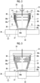
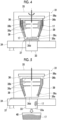
- the shutter 37 is opened.
- the scraper 39 is rotated. Accordingly, the resin aggregate 17 inside the rotating body 36 passes through the inner portion 33a of the induction path 33 and is discharged to the outside.
- air may be jetted into the rotating body 36. Accordingly, the resin aggregate 17 is easily discharged to the outside.
- the resin aggregate is also called sludge.
- the washing method is a developing method, and washing is development. Through washing, the flexographic printing plate precursor 32 is developed, obtaining a flexographic printing plate. For this reason, the washing method corresponds to the manufacturing method of a flexographic printing plate. Similarly, the washing method described below corresponds to the manufacturing method of a flexographic printing plate.
- the washing solution Q is supplied to the developing brush 22 through the pipe 28 via the filter 27 by the pump 26.
- a timing when the resin aggregate is removed by the regeneration treatment apparatus 14 is, for example, a case where the concentration of solid contents of the washing solution Q in the tank 25 exceeds a set concentration or a case where a treatment area of the flexographic printing plate precursor 32 exceeds a set treatment area.
- the used washing solution in the tank 25 is supplied to the rotating body 36 of the regeneration treatment apparatus 14 by the pump 16, as in the first example of the regeneration treatment method described above, the resin aggregate is removed from the used washing solution, and the used washing solution from which the resin aggregate is removed is transferred to the tank 25 through the pipe 15b.
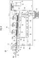
- the washout processor 12a has a developing tank 42 and the lid 43 of the developing tank 42.
- the lid 43 is openable and closable with respect to the developing tank 42, and for example, the developing tank 42 and the lid 43 are connected to each other using a hinge. In a state where the lid 43 is closed as shown in Fig. 6 , a back surface 43b of the lid 43 faces the liquid level Qs of the washing solution Q in the developing tank 42.
- a brush 44 is disposed on a bottom surface 42b side in the developing tank 42. In a state where the brush 44 is fixed, development is performed on the flexographic printing plate precursor 32.
- the brush 44 is obtained, for example, by bundling bristles 44b perpendicular to a quadrangular substrate 44a in plan view.
- the substrate 44a is fixed into the developing tank 42 by a fixing unit (not shown).
- the shape of the substrate 44a is the shape of the brush 44.
- the shape of the substrate 44a is not limited to a quadrangle in plan view.
- a material for the bristles of the brush 44 is not particularly limited, and for example, a known material used for the development of the flexographic printing plate precursor 32, such as nylon 6,6, nylon 610, nylon 612, polybutylene terephthalate (PBT), and polyethylene terephthalate (PET), can be used as appropriate.
- a known material used for the development of the flexographic printing plate precursor 32 such as nylon 6,6, nylon 610, nylon 612, polybutylene terephthalate (PBT), and polyethylene terephthalate (PET)
- a supply port 45a is provided in a side surface 42c of the developing tank 42.
- a blowout port 45b is provided at the supply port 45a in the developing tank 42.
- a first valve 50 is provided at the supply port 45a via a pipe 51.
- the tank 25, the pump 26, the filter 27, and a heater 49 are provided from a third valve 54 side between the first valve 50 and the third valve 54.
- the tank 25 is connected to the regeneration treatment apparatus 14.
- the washing solution Q in the developing tank 42 is taken in from the output port 46a via the suction port 46b by the pump 26, goes via the filter 27 and the heater 49, and is supplied into the developing tank 42 from the supply port 45a via the blowout port 45b as a regenerated washing solution as will be described later.
- the pump 26 is a supply unit that supplies the washing solution Q from which a non-exposed portion is removed by the filter 27 to the developing tank 42, and a pump that transfers a known liquid is usable as appropriate.
- the pump 26 corresponds to the supply unit that supplies the washing solution Q from which the resin aggregate is removed to the developing tank 42.
- the filter 27 is a filter that removes solid contents generated by development from the washing solution Q and removes the solid contents in the washing solution after the development.
- the filter 27 can reduce the concentration of the solid contents. Even with the filter 27, a regenerated washing solution is obtained from the washing solution after the development, that is, a fatiqued developer. For this reason, the regenerated washing solution is supplied to the developing tank 42 through the filter 27.
- the filter 27 is not particularly limited insofar as a non-exposed portion or the resin aggregate such as the solid contents in the washing solution after development can be separated out and is determined as appropriate according to the sizes of solid contents to be separated out.
- a ceramic filter is used. It is preferable that the filter 27 can separate out, for example, a solid content having a particle diameter of 1 ⁇ m or less.
- the regenerated washing solution is a solution obtained by reducing the concentration of the resin aggregate from the used washing solution with the filter 27 or the filter 59 to be described later.
- the heater 49 adjusts the temperature of the washing solution Q supplied into the developing tank 42 to a determined temperature, for example, a range of 40°C to 50°C. A liquid temperature of the washing solution Q is adjusted by the heater 49.
- the configuration of the heater 49 is not particularly limited, and a known configuration is usable as appropriate.
- a temperature adjusting device (not shown) that has the heater 49 which adjusts the liquid temperature of the washing solution Q may be included, or the temperature adjusting device may be the heater 49.
- a liquid feeding port 58 is provided in a side surface 42e of the developing tank 42.
- a second valve 52 is provided at the liquid feeding port 58 via a pipe 53.
- the second valve 52 is connected between the heater 49 and the first valve 50.
- the washing solution Q after development is supplied to the liquid feeding port 58 via the filter 27 and the heater 49.
- the filter 59 is provided on an overflow port facing the liquid feeding port 58.
- a port from which a liquid overflowing from the developing tank 42 due to inflow of the washing solution Q to the developing tank 42 is discharged is referred to as the overflow port.
- the filter 59 consists of a nonwoven fabric made of a polyolefin-based resin, is spread in the overflow port, and allows an overflowing liquid caused by the inflow of the washing solution Q to the developing tank 42 to pass therethrough.
- the filter 59 removes a non-exposed portion of the flexographic printing plate precursor 32 which is generated by development from the washing solution Q.
- a resin component of the flexographic printing plate precursor 32, which is the non-exposed portion, has a low specific gravity and thereby aggregates or floats on the liquid level Qs while diffusing in the washing solution Q. Relatively large floating substances floating on the liquid level Qs are discharged from the overflow port with the inflow of the washing solution Q and are captured by the filter 59.
- a fourth valve 56 is provided at the overflow port comprising the filter 59 via a pipe 57.
- the washing solution Q flows from the liquid feeding port 58 in the developing tank 42 to form a flow of the washing solution Q from the liquid feeding port 58 toward the filter 59.
- the direction Fi from the liquid feeding port 58 toward the filter 59 is not particularly limited insofar as the direction Fi is an intersecting direction to cross a width Ws of the flexographic printing plate precursor 32, but is preferably a direction orthogonal to a traveling direction D L of the flexographic printing plate precursor 32.
- orthogonal direction in a case where the term "orthogonal" is defined as 90°, the orthogonal direction described above is allowed to be in a range of 80° to 100°.
- a flow creation unit 67 that flows the washing solution Q in the intersecting direction to cross the width Ws of the flexographic printing plate precursor 32 is composed of the pump 26, the filter 27, the heater 49, the filter 59, the second valve 52, and the fourth valve 56.
- one crank 62 of the two cranks 62 is connected to the motor 60.
- the two cranks 62 are connected to each other, and in a case where the one crank 62 rotates, the other crank 62 rotates in synchronization with the rotation. For this reason, in a case where the one crank 62 is rotated by the motor 60, the other crank 62 also rotates in synchronization with the rotation. Accordingly, the flexographic printing plate precursor 32 moves eccentrically.
- a development unit 68 is composed of the motor 60, the cranks 62, the fixing member 64, and the brush 44.
- the brush 44 does not move, but the flexographic printing plate precursor 32 is moved in the washing solution Q such that the image forming surface of the flexographic printing plate precursor 32 moves eccentrically on the brush 44.
- the lid 43 is opened, and the support plate 65 is fixed to the fixing member 64, for example, using a gluing agent. Accordingly, the flexographic printing plate precursor 32 can be fixed to the fixing member 64.
- the lid 43 is opened, and the support plate 65 is removed from the fixing member 64.
- solid contents are likely to be stuck to the plate surface 32a of the flexographic printing plate precursor 32 on a liquid level Qs side due to the surface tension of the washing solution Q in a case where the solid contents float on the liquid level Qs of the washing solution Q.
- a liquid flow rate of the washing solution Q is preferably 50 cm/sec or more. In a case where the liquid flow rate of the washing solution Q is 50 cm/sec or more, attachment of solid contents or the like to the developed flexographic printing plate precursor 32 can be more reliably prevented, which is preferable.
- An upper limit of the liquid flow rate of the washing solution Q is not particularly limited, but is 200 cm/sec or less based on pump performance or the like.
- the liquid flow rate of the washing solution Q is a minimum speed of the washing solution Q and is, for example, a liquid flow rate at the side surface 42f of the developing tank 42.
- the liquid flow rate of the washing solution Q can be measured using a thermal flow meter or the like, and specifically, for example, SI5007 manufactured by ifm effector or the like is used.
- a portion in contact with the resin aggregate is, for example, an inner wall surface 42g of the developing tank 42, particularly the gas-liquid interface of the washing solution Q at the inner wall surface 42g. That is, the liquid level Qs of the washing solution Q is a portion 42h that is in contact with the developing tank 20.
- the inner wall 25a of the tank 25 is also the portion in contact with the resin aggregate, as in the washout processor 12 described above.
- the portion in contact with the resin aggregate is composed of polyethylene having a critical surface tension of 31 mN/m or less and a dynamic friction coefficient of 0.2 or less or an average molecular weight of 750,000 to 6,000,000.
- the portion in contact with the resin aggregate can be configured to have the same composition as that of the washout processor 12 described above.
- the portion in contact with the resin aggregate may have a configuration integrated with the developing tank 42 or may have a separate configuration.
- a washing method of the washout processor 12a will be described. Through washing as described above, the flexographic printing plate precursor 32 is developed, obtaining a flexographic printing plate.
- the imagewise exposed flexographic printing plate precursor 32 is attached to the support plate 65, and the support plate 65 is attached to the fixing member 64.
- the inside of the developing tank 42 is filled with the washing solution Q.
- the lid 43 is closed.
- the flexographic printing plate precursor 32 is immersed in the washing solution Q.
- the image forming surface of the flexographic printing plate precursor 32 that is, the plate surface 32a of the flexographic printing plate precursor 32 is brought into contact with the bristles 44b of the brush 44.
- the one crank 62 is rotated by the motor 60, the other crank 62 is also rotated in synchronization with the rotation, the flexographic printing plate precursor 32 is moved eccentrically, and the flexographic printing plate precursor 32 is developed in a state of being immersed in the washing solution Q.
- the temperature of the washing solution Q is adjusted at a constant temperature in a range of 40°C to 50°C by the heater 49, and the washing solution Q is kept in a state of being uniformly circulated in the developing tank 42.
- the washing solution Q that has passed through the filter 27 is supplied from the supply port 45a into the developing tank 42 via the blowout port 45b, the washing solution Q in the developing tank 42 is taken in from the output port 46a via the suction port 46b by the pump 26 and goes via the filter 27 and the heater 49, and the washing solution Q is supplied into the developing tank 42.
- the washing solution Q is circulated from the side surface 42c toward the side surface 42d of the developing tank 42. Accordingly, a flow of the washing solution Q from the side surface 42c toward the side surface 42d of the developing tank 42 is formed.
- the washing solution Q is flowed parallel to a front surface of the flexographic printing plate precursor 32. In this case, in a state where the first valve 50 and the third valve 54 are open and a state where the second valve 52 and the fourth valve 56 are closed, a circulation path for the washing solution Q is configured.
- the washing solution Q As described above, as the washing solution Q is flowed from the blowout port 45b, the washing solution Q is taken in from the suction port 46b, and a flow of the washing solution from the side surface 42c toward the side surface 42d of the developing tank 42 is formed, the washing solution Q flowed in from the blowout port 45b simultaneously flows up and down with respect to the brush 44, and deposit of aggregated sediments on an edge part of the brush 44 and sedimentation of an unhardened portion on a bottom portion of the developing tank 42 can be suppressed.
- the lid 43 is opened, and the developed flexographic printing plate precursor 32 is taken out from the washing solution Q.
- a solid content and a photosensitive resin aggregate of a non-exposed portion scraped off the flexographic printing plate precursor 32 sediment on the edge part of the brush 44 or the bottom portion of the developing tank 42.
- a resin component, which is the non-exposed portion of the flexographic printing plate precursor 32, has a low specific gravity and thereby aggregates or floats on the liquid level Qs while diffusing in the washing solution Q.
- the flexographic printing plate precursor 32 In a case of taking out the flexographic printing plate precursor 32 from the washing solution Q, in order to prevent solid contents floating in the washing solution Q from being attached to the flexographic printing plate precursor 32 even in a case where a washing solution circulation state where the solid contents are unlikely to be attached to the flexographic printing plate precursor 32 is kept in the washing solution Q, for example, the flexographic printing plate precursor 32 is moved in the traveling direction D L after development. In a case where the flexographic printing plate precursor 32 is raised from the washing solution Q, a flow of the washing solution Q is formed in the direction intersecting the traveling direction D L of the flexographic printing plate precursor 32 at an interface between the flexographic printing plate precursor 32 and the washing solution Q.
- the configuration of the washout processor 12a is not limited to the configuration shown in Fig. 6 and may be other configurations.
- Fig. 8 is a schematic side view showing a third example of the washout processor according to the embodiment of the present invention.
- Fig. 9 is a schematic plan view showing the third example of the washout processor according to the embodiment of the present invention.
- Figs. 8 and 9 the same components as those of the washout processor 12a shown in Figs. 6 and 7 will be assigned with the same reference numerals, and detailed description thereof will be omitted.
- a control unit is not shown in Figs. 8 and 9 , but each unit of a washout processor 12b is controlled by the control unit.
- the washout processor 12b shown in Fig. 8 has a development unit 70 that removes and develops a non-exposed portion of an imagewise exposed flexographic printing plate precursor using the washing solution Q.
- the first valve 50 is connected to the side surface 42e of the developing tank 42 via the pipe 51.
- the second valve 52 is connected to the side surface 42e of the developing tank 42 via the pipe 53.
- the third valve 54 is connected to the side surface 42e of the developing tank 42 via the pipe 55.
- the development unit 70 is disposed at the developing tank 42 and has a plurality of brushes 71.
- a plurality of transport rollers 72 are provided in the developing tank 42.
- a support body 76 that supports the flexographic printing plate precursor 32 is provided between the transport rollers 72.
- Each brush 71 is disposed on each support body 76.
- the brushes 71 are disposed in three lines with three brushes as a line, the number of brushes 71 and the number of lines are not particularly limited.
- a brush shape may be a polygon in addition to a circle, is not particularly limited, and is determined by the configuration of the washout processor 12b as appropriate.
- the support body 76 shown in Fig. 8 may not be included.
- the brush 71 is connected to a connecting pipe 73.
- the connecting pipe 73 is connected to the tank 25, the pump 26, the filter 27, and the heater 49, and a fifth valve 50b is provided at the connecting pipe 73.
- the washing solution Q or a regenerated washing solution is supplied to the brushes 71 through the connecting pipe 73.
- By opening and closing the fifth valve 50b the supply of the washing solution Q or the regenerated washing solution to the brushes 71 is controlled.
- tank 25 is connected to the third valve 54 and the fourth valve 56. Further, the tank 25 is connected to the regeneration treatment apparatus 14.
- a method of carrying in the flexographic printing plate precursor 32 in a state of being fixed to the support plate 65 may be adopted, like the washout processor 12a shown in Fig. 6 .
- the flexographic printing plate precursor 32 is fixed to the support plate 65 such that an imagewise exposure surface is on a brush side.
- the flexographic printing plate precursor 32 is transported to the developing tank 42 along one determined transport path and is carried out from the developing tank 42.
- the flexographic printing plate precursor 32 carried into the washing solution Q and the flexographic printing plate precursor 32 carried out from the washing solution Q pass through the same region. For this reason, in the washout processor 12b, a first region Di where the flexographic printing plate precursor 32 is carried into the washing solution Q of the developing tank 42 and the second region D 2 where the flexographic printing plate precursor 32 is carried out from the washing solution Q of the developing tank 42 are the same region.
- regions for carrying-in and carrying-out of the flexographic printing plate precursor 32 may include a transport error and are not limited to a complete match.
- the washout processor 12b is not limited thereto, and the first region Di and the second region D 2 may be regions different from each other.
- the first region Di and the second region D 2 can be made regions different from each other.
- a transport path difference between carrying-in and carrying-out of the flexographic printing plate precursor 32 is a difference exceeding a transport error of carrying-in and carrying-out of the flexographic printing plate precursor 32 described above.
- the plurality of brushes 71 are rotated about a rotation axis (not shown) by a driving unit (not shown).
- the washing solution Q or a regenerated washing solution is supplied to the brushes 71 via the rotation axis.
- the washing solution Q or the regenerated washing solution is supplied from the brushes 71 to the plate surface 32a of the flexographic printing plate precursor 32.
- the rinsing liquid supply unit 77a supplies, for example, a rinsing liquid from a nozzle to the plate surface 32a of the flexographic printing plate precursor 32.
- the liquid drain nozzle 77b removes the rinsing liquid supplied to the flexographic printing plate precursor 32 by the rinsing liquid supply unit 77a by jetting a gas or removes the rinsing liquid by sucking a gas.
- the configuration of the liquid drain nozzle 77b is not particularly limited, and various types of pumps can be used.
- the washing solution Q of the developing tank 42 is circulated via the filter 27 and the heater 49 by the pump 26 with the first valve 50 and the third valve 54 opened and is heated to a set temperature.
- the set temperature is a temperature of 50°C and the temperature is in a constant state of 50°C
- the first valve 50 is closed, the fifth valve 50b is opened, and the washing solution Q is supplied to a brush 71 side, circulating the washing solution Q.
- the rinsing unit 77 raises the flexographic printing plate precursor 32 from the washing solution Q while jetting a rinsing liquid to the plate surface 32a of the flexographic printing plate precursor 32.
- the washing solution Q is flowed by the pump 26.
- the second region D 2 see Fig. 9
- a flow of the washing solution Q is formed in the direction Fi (see Fig. 9 ) as described above. Accordingly, solid contents are prevented from being attached to the flexographic printing plate precursor 32 as the solid contents floating in the second region D 2 are swept away by the flow of the washing solution Q, thereby obtaining a good development finish.
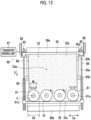
- Figs. 10 to 13 the same components as those of the washout processor 12a shown in Figs. 6 and 7 will be assigned with the same reference numerals, and detailed description thereof will be omitted.
- Fig. 11 a partition member 100 and a restricting member 101 are not shown.
- the flexographic printing plate precursor 32 can be developed by making the flexographic printing plate precursor go around a plurality of times.
- the flexographic printing plate precursor 32 has a small thickness of approximately several millimeters and is flexible enough to be curved and transported in a developing tank 84.
- the imagewise exposed flexographic printing plate precursor 32 which is in a state of being immersed in the washing solution Q and being transported, is developed with a non-exposed portion (not shown) of the flexographic printing plate precursor 32 removed.
- the washout processor 12c is an apparatus that performs development while transporting the flexographic printing plate precursor 32 along the determined transport path. In a washing method using the washout processor 12c, the flexographic printing plate precursor 32 is developed while being transported along the determined transport path Dp.
- the expression that while transporting the flexographic printing plate precursor 32 described above and a state where the flexographic printing plate precursor 32 is transported mean moving the flexographic printing plate precursor 32 along the transport path Dp.
- a transport driving unit 87 is connected to one of the plurality of gears 85.
- the gears 85 are rotated by the transport driving unit 87, and the transport chains 86 move in a specific direction.
- a method of connecting between the gears 85 and the transport driving unit 87 is not particularly limited.
- the gears and the transport driving unit may be connected to each other by a shaft or the like or may be connected to each other using a chain or a belt.
- the transporting unit 80 is composed of the gears 85, the transport chains 86, and the transport driving unit 87.
- the flexographic printing plate precursor 32 is transported by the transporting unit 80 in a state of being immersed in the washing solution Q in the developing tank 84.
- the tension adjusting unit 88 that adjusts the tension of the transport chain 86 is provided at an end part of the member 83a in order to adjust the tension of the flexographic printing plate precursor 32 during transporting.
- the tension of the flexographic printing plate precursor 32 during transporting can be adjusted by the tension adjusting unit 88, and the flexographic printing plate precursor 32 is prevented from being loosened during transporting.
- the transporting unit 80 may have a guide mechanism that guides the transport chain 86.
- the guide mechanism can suppress meandering of the transport chain 86 or the like.
- the guide mechanism is composed of, for example, a member that is provided on an opposite side of the transport chain 86 where the flexographic printing plate precursor 32 is disposed and is inserted between rollers (not shown) of the transport chains 86.
- This member is composed of, for example, high molecular weight polyethylene or a fluororesin such as polytetrafluoroethylene (PTFE).
- a turn bar 89a and a turn bar 89b are provided at the beam members 83b at ends of the members 83a respectively in the longitudinal direction.
- the turn bars 89a and 89b are composed of a semi-cylindrical member, and the semi-cylindrical member is provided with a plane portion facing a beam member 83b side.
- the semi-cylindrical turn bars 89a and 89b are provided at bending parts composed of the curved transport passages. That is, the curved transport passages Dpc are composed of the semi-cylindrical turn bars 89a and 89b, and the flexographic printing plate precursor 32 is transported along the surfaces of the turn bars 89a and 89b. In this case, a back surface 32b of the flexographic printing plate precursor 32 comes into contact with the turn bars 89a and 89b.
- the turn bars 89a and 89b each are composed of a semi-cylindrical member having a size corresponding to the curvature of the curved transport passage Dpc or the like.
- the turn bars 89a and 89b are brought into contact with the flexographic printing plate precursor 32, at least, surfaces brought into contact with the flexographic printing plate precursor 32 preferably have a low frictional resistance. As the frictional resistance is low, the flexographic printing plate precursor 32 can be smoothly transported without damaging the back surface 32b.
- the turn bars 89a and 89b suppress tension fluctuations in the curved transport passages Dpc during transporting of the flexographic printing plate precursor 32.
- the turn bar 89a and the turn bar 89b are provided at the ends of the members 83a in the longitudinal direction, and the turn bar 89b is immersed in the developing tank 84 storing the washing solution Q.
- the flexographic printing plate precursor 32 is attached to a trailing end leader 93 in a state where the flexographic printing plate precursor 32 is hung on the turn bar 89a among the turn bar 89a and the turn bar 89b.
- the turn bar 89a moves forward and backward with respect to the curved transport passage Dpc.
- the turn bar is brought into contact with the flexographic printing plate precursor 32.
- a transport length of the flexographic printing plate precursor 32 is shortened, and a short pass state is caused.
- the turn bar 89a moves up and down with respect to the beam members 83b, the turn bar moves forward and backward with respect to the curved transport passage Dpc.
- a linear motion mechanism using a solenoid is provided, for example, between the turn bar 89a and the beam member 83b.
- a configuration where the turn bar 89a is lowered in a state where the solenoid is turned off and the turn bar 89a is raised in a state where the solenoid is turned on is adopted. Accordingly, in a case of fixing the flexographic printing plate precursor 32, the turn bar 89a can be lowered.
- the turn bar 89a functions as a tension applying unit. After fixing both a leading end and a trailing end of the flexographic printing plate precursor 32 by a leading end leader 92 and the trailing end leader 93 shown in Fig.
- the leading end leader 92 and the trailing end leader 93 shown in Fig. 12 are collectively referred to as a leader.
- the tension in a case of fixing the flexographic printing plate precursor 32 is the tension of the flexographic printing plate precursor 32 in a state where the turn bar 89a is lowered.
- the tension after fixing the flexographic printing plate precursor is the tension of the flexographic printing plate precursor 32 in a state where the turn bar 89a is raised.
- the magnitude of the tension of the flexographic printing plate precursor 32 can be identified by the tension of the flexographic printing plate precursor 32.
- a state where the turn bar 89a is raised is visually checked with the solenoid turned on, and a position where the solenoid is attached or a stopper is adjusted to cause a state where vertical creases and horizontal creases are not generated.
- an air cylinder or a hydraulic actuator may be used as the linear motion mechanism, and the attachment position or the stopper is adjusted and fixed such that any linear motion mechanism is in an appropriate tension state in a case of being turned on.
- linear motion can be randomly made not only in an on and off states but also in a certain range, and the tension can be finely adjusted.
- linear motion mechanisms are configured to operate the tension applying unit via a load cell or a strain gauge, a tension applied to the flexographic printing plate precursor 32 can be measured.
- linear motion can be randomly made not only in on and off states but also a certain range, and a tension applied to the flexographic printing plate precursor 32 can be finely adjusted.
- the linear motion mechanisms are configured to operate the tension applying unit via a load cell or a strain gauge, a tension applied to the flexographic printing plate precursor 32 can be measured. By quantifying a tension range in a state where vertical creases and horizontal creases are not visually generated in the flexographic printing plate precursor 32, an appropriate tension state according to various types such as the width, the length, and the thickness of the flexographic printing plate precursor 32 is easily set.
- a tension controller is preferable.
- the tension applying unit is not limited to the turn bar 89a described above, and a roller (not shown) can also be used instead of the turn bar 89a.
- the roller is configured to move forward and backward with respect to the curved transport passage Dpc, and a tension can be applied to the flexographic printing plate precursor 32 in a case where the roller has entered the curved transport passage Dpc.
- the surfaces of the turn bars 89a and 89b, which are brought into contact with the flexographic printing plate precursor 32, are composed of, for example, resin layers, plating layers, or diamond-like carbon layers (DLC layers).
- the resin layer can be formed of a fluororesin, such as polytetrafluoroethylene (PTFE) and high-density polyethylene.
- the plating layer is, for example, hard chrome plating.
- a titanium nitride (TiN) layer or the like can be used.
- a nonwoven fabric can also be used as the turn bars 89a and 89b. In a case of using the nonwoven fabric, an attachment on the back surface 32b of the flexographic printing plate precursor 32 can be removed.
- a plurality of uneven portions may be formed in the surfaces of the turn bars 89a and 89b, which are brought into contact with the flexographic printing plate precursor 32.
- a contact area reduces, and a frictional resistance decreases.
- An example in which the plurality of uneven portions are formed includes a metal plate such as an embossed stainless steel plate.
- a surface brought into contact with the flexographic printing plate precursor 32 is preferably a plane. As the surface brought into contact with the flexographic printing plate precursor 32 is a plane, the flexographic printing plate precursor 32 can be efficiently washed.
- the back plate portion 90 is composed of, for example, a metal.
- the metal is preferably stainless steel, titanium, or the like
- the surface of the back plate portion 90 brought into contact with the flexographic printing plate precursor 32 may be plated, and the plating is preferably hard chrome plating and is more preferably diamond-like carbon (DLC) processing.
- DLC diamond-like carbon
- surface treatment with titanium nitride (TiN) or the like may be performed on the surface brought into contact with the flexographic printing plate precursor 32.
- nip rolls may be provided to face the back plate portion 90 at intervals in the longitudinal direction of the members 83a.
- the nip rolls suppress deflection or the like during transporting so that the flexographic printing plate precursor 32 can be stably transported, and even in a case where a brush 91 rotates or moves particularly during development, the flexographic printing plate precursor 32 can be stably transported.
- the nip rolls are not limited to three.
- the plate surface 32a of the flexographic printing plate precursor 32 for example, rubber rollers, sponge rollers, rotary brushes, or the like are preferably used as the nip rolls.
- the flexographic printing plate precursor 32 Since the flexographic printing plate precursor 32 has flexibility as described above, there is a possibility that a non-exposed portion cannot be efficiently removed by the brush 91 due to deflection or the like in a case of being rubbed against the brush 91.
- the back plate portion 90 described above is provided, the back surface 32b of the flexographic printing plate precursor 32 is supported by the back plate portion 90 in a case of removing the non-exposed portion by the brush 91, so that the non-exposed portion can be efficiently removed.
- the back plate portion 90 functions as a transport guide, and thus the flexographic printing plate precursor 32 can be more stably transported by the back plate portion 90.
- the development unit 81 may be configured such that a plurality of brushes 91, for example, four brushes 91 are arranged in a line in the direction Dw.
- the brush 91 is disposed such that a rotation axis C is in a direction perpendicular to the plate surface 32a of the flexographic printing plate precursor 32.
- the rotation about the rotation axis C of the brush 91 described above is rotation of the brush 91 with the rotation axis C as a rotation center, and the brush 91 spins.
- the rotation axis C is a fixed axis passing through one point in the brush 91.
- a rotation shaft portion 91a is provided at the brush 91, and a central axis of the rotation shaft portion 91a is the rotation axis C.
- the rotation shaft portion 91a functions as a rotation drive shaft that is rotated as power is transmitted from the driving unit, and the brush 91 spins, for example, in a rotation direction r as the rotation shaft portion 91a is rotated.
- the four brushes 91 in a width direction of the flexographic printing plate precursor 32, that is, the direction Dw orthogonal to a transport direction D. That is, it is preferable to swing the plurality of brushes 91 in the direction Dw. In this case, it is preferable to move by a distance of one third or more of a diameter DB (see Fig. 12 ) of the brush 91.
- the distance by which the brush 91 is moved in the direction Dw is called a swing width Mb.
- a plurality of brushes for example, at least two brushes may be simultaneously driven by one motor instead of rotating each brush.
- the four brushes 91 may be simultaneously driven by one motor instead of rotating each brush 91. Accordingly, the number of motors can be reduced, and thus the device can be decreased in size.
- the rotation speed can be changed for each brush 91 by providing a transmission. Accordingly, the number of motors can be reduced, and thus the device can be decreased in size.
- the rotation speed can be changed for each brush 91 by providing a transmission.
- a configuration where two brushes 91 are disposed in the transport direction D of the transport path Dp may be adopted.
- the washout processor 12c has at least two types of brushes used in development, and one type of the at least two types of brushes is a brush of which the rotation axis C is disposed in a direction perpendicular to the flexographic printing plate precursor 32. By disposing the rotation axis C parallel to the plate surface 32a of the flexographic printing plate precursor 32, development can be efficiently performed.
- a roller brush that is used in finishing of development may be disposed on an upstream side (first region Di) of the transport path Dp for the flexographic printing plate precursor 32 in the transport direction D.
- the roller brush is disposed in a state of being immersed in the liquid level Qs of the washing solution Q. Having the roller brush that is used in finishing of development is preferable since on-plate residues or the like are removed, but it is not always necessary to provide the roller brush.
- a plurality of fixing units are provided on the transport chain 86 at equal intervals along a longitudinal direction of the transport chain 86.
- the leading end leader 92 and the trailing end leader 93 are fixed to the fixing units.
- the longitudinal direction of the transport chain 86 is the same direction as the transport direction D.
- a method of fixing the leading end leader 92 to the transport chain 86 is not particularly limited, and the leading end leader is fixed to the transport chain through at least one of fixing methods using hooking, screwing, sandwiching, or a magnetic force.
- the hooking is, for example, a method of providing a bending portion at the leading end leader 92 and hooking the bending portion to the fixing unit.
- the screwing is, for example, a method of fixing the bending portion to the fixing unit using a bolt and a nut.
- a method of forming a female thread in the fixing unit and fixing the bending portion to the fixing unit using a screw is also included in screwing.
- the sandwiching is, for example, a method of collectively sandwiching and fixing the bending portion and the fixing unit to each other using a member such as a clip.
- a transporting tension fluctuates in some cases due to fluctuations of transporting during transporting. Transporting becomes unstable due to the fluctuations of the transporting tension.
- the flexographic printing plate precursor 32 expands and contracts in some cases due to the transporting tension during transporting. For this reason, it is preferable to suppress the fluctuations of the transporting tension and effects of expansion and contraction or the like of the flexographic printing plate precursor 32.
- the leader it is preferable for the leader to have a leader mechanism portion (not shown) that expands and contracts with respect to the traveling direction of the flexographic printing plate precursor 32.
- the leader mechanism portion can reduce the fluctuations of the transporting tension and the effects of expansion and contraction or the like of the flexographic printing plate precursor 32 by expanding and contracting with respect to the traveling direction of the flexographic printing plate precursor 32.
- the transport path Dp for the flexographic printing plate precursor 32 is the one-direction transport path or the go-around transport path since processing by the rinsing unit 82 is necessary after development.
- the first moving direction is the direction Dw
- a second moving direction is the transport direction D.
- the moving directions of the brush 91 are not particularly limited.
- the entire plate surface 32a of the flexographic printing plate precursor 32 can be uniformly rubbed by the brush 91, and development uniformity improves. Further, the development speed also improves by moving the brush 91 in the two directions orthogonal to each other.
- the brush 91 Since the brush 91 is disposed by being immersed in the washing solution Q, the washing solution Q attached to the brush 91 is not dried, and fixing of the non-exposed portion or the like removed by the brush 91 to the brush 91 as development residues is suppressed.
- the rotation shaft portion is provided on the substrate. Accordingly, the rotation axis C is provided in the brush 91. In addition, by adjusting a position where the rotation shaft portion is provided, the position of the rotation axis C can be adjusted in the brush 91.
- the rotation shaft portion can also be provided at a place other than the center of the substrate, but in this case, the brush 91 moves eccentrically.
- the center of the brush 91 is the center of the substrate of the brush 91, that is, the geometric center of a shape obtained by projecting the substrate onto a plane.
- the center of the circle is the center of the brush 91.
- a point where diagonals of the rectangle intersect each other is the center of the brush 91.
- the brush 91 rotates stably in a case where the brush 91 spins. For this reason, the brush can be stably rotated even in a case where the rotation speed is increased in order to increase the rotation speed of the brush 91. Accordingly, the development speed can be increased.
- the brush 91 is smaller than the flexographic printing plate precursor 32 as described above. As the brush 91 is small, the brush 91 is moved and performs development on the flexographic printing plate precursor 32, the pressure of the brush 91 can be made uniform, and development uniformity can be improved.
- the washout processor can be simplified.
- an equivalent circle diameter that is, a diameter corresponding to the brush area is used as the diameter in a case where the outer shape of the substrate described above is circular.
- the brush 91 rotates and performs development, but the rotation speed of the brush 91 is preferably 10 revolutions per minute (rpm) to 2,000 rpm, more preferably 20 to 800 rpm, and even more preferably 30 to 200 rpm.
- the substrate of the brush 91 holds the bristles, and for example, the bristles are implanted in a bundle. Insofar as the substrate can hold the bristles and does not become deteriorated due to the washing solution Q, there is no particular limitation.
- the material for the bristles of the brush 91 is not particularly limited.
- natural fibers such as coir
- any material that can be made into a fibrous form such as a metal, polyamide, polyester, vinyl chloride, vinylidene chloride, polyimide, and polyacrylonitrile, are suitably used.
- each bristle of the brush is preferably approximately 10 ⁇ to 1 mm and may be implanted in a bundle or be independently implanted within several bristles.
- the implanting interval is preferably approximately 1 to 20 mm, and in a case of being implanted in a bundle, the diameter of the bundle is preferably approximately 1 to 10 mm.
- the length of each of the bristles of the brush is preferably approximately 2 to 50 mm and more preferably 5 to 25 mm. In a case where the length of each of the bristles of the brush is 5 to 25 mm, the leading end leader 92 and the trailing end leader 93 for transport can be passed through, a brush force becomes strong so that independent small dot performance is obtained, and a development speed thereof also increases.
- each of the bristles may vary in one brush 91, and it is preferable that bristles in a central portion are long.
- the thickness of each of the bristles in one brush 91 may vary, or the density of the bristles in one brush 91 may vary.
- the development speed in the first half of development can be increased, and a development treatment time can be shortened.
- wavy bristles which are not uncurled bristles and which are called curly bristles, can be used rather than straight bristles. Since the abrasive material is contained, abrasion of the brush can be reduced, and the brush life can be extended.
- Examples of a commercially available bristle material include Sungrid (product name) manufactured by Asahi Kasei Corporation, Tragrid (product name) manufactured by Toray Industries, Inc., and Tynex (product name) manufactured by DuPont.
- Sungrid product name
- Tragrid product name
- Tynex product name
- the brush disposed on a second region D 2 side there is a possibility that scratches are generated on the flexographic printing plate precursor 32 depending on a type of an abrasive material, and the brush can be used properly according to the region.
- the bristles are provided in a region of 30% or more of the substrate.
- the fact that the bristles are provided in an area of 30% or more of the substrate of the brush 91 means that the area of the bristles is 30%.
- the brush 91 is rotated by the driving unit in a state where the rotation axis C of the brush 91 passes through the plate surface 32a of the flexographic printing plate precursor 32.
- the angle ⁇ is preferably 30° ⁇ ⁇ ⁇ 90°, more preferably 45° ⁇ ⁇ ⁇ 90°, and most preferably 60° ⁇ ⁇ ⁇ 90°.
- the brush 91 By setting the angle ⁇ to 60° ⁇ ⁇ ⁇ 90°, the brush 91 can be uniformly brought into contact with the plate surface 32a of the flexographic printing plate precursor 32, and development can be performed even in a case where the pressure of the brush 91 is increased. For this reason, both the development uniformity and the development speed can be increased. As described above, it is most preferable that the rotation axis C of the brush 91 is perpendicular to the plate surface 32a of the flexographic printing plate precursor 32.
- the angle ⁇ can be obtained as follows. First, an image of a state where the brush 91 is disposed on the plate surface 32a of the flexographic printing plate precursor 32 is acquired, and a line corresponding to the rotation axis C of the brush 91 and a line corresponding to the plate surface 32a of the flexographic printing plate precursor 32 are acquired from the image. Next, an angle formed by the two lines is acquired. Accordingly, the angle ⁇ can be obtained.
- a state where the rotation axis C of the brush 91 passes through the plate surface 32a of the flexographic printing plate precursor 32 means passing through the plate surface 32a of the flexographic printing plate precursor 32 or a surface obtained by expanding the plate surface 32a of the flexographic printing plate precursor 32 in a case of the rotation axis C or in a case where the rotation axis C is extended, and shows a disposition relationship between the brush 91 and the flexographic printing plate precursor 32.
- the rotation axis C of the brush 91 does not pass through the actual plate surface 32a of the flexographic printing plate precursor 32 in some cases depending on the inclination of the rotation axis C, but the rotation axis C of the brush 91 is not limited to actually passing through the plate surface 32a of the flexographic printing plate precursor 32 as described above.
- the position of the brush 91 with respect to the plate surface 32a of the flexographic printing plate precursor 32 may be fixed.
- a configuration where the brush approaches or is spaced apart from the plate surface 32a of the flexographic printing plate precursor 32 may be adopted.
- the pressure of the brush 91 can be adjusted with respect to the plate surface 32a of the flexographic printing plate precursor 32. Accordingly, the pressure of the brush 91 can be increased, and the development speed can be improved.
- the material for the bristles of the brush 91, the length of each bristle, the thickness of each bristle, or the like corresponds to the pressure.
- the bristles of the central portion in one brush 91 may be made long, the thickness of each of bristles in one brush 91 may be changed, or the density of the bristles in one brush 91 may be changed.
- the brush 91 can be spaced apart from the plate surface 32a of the flexographic printing plate precursor 32, the brush 91 can be lifted from the plate surface 32a of the flexographic printing plate precursor 32. Accordingly, in a case where development residues of the brush 91 are attached, the development residues can be removed from the brush 91.
- the brush 91 may move at all times during development, or the brush 91 may rotate only in a case where the flexographic printing plate precursor 32 is transported to the developing tank 84.
- a sensor (not shown) that detects the flexographic printing plate precursor 32 is provided above the developing tank 84, a time when the brush 91 is reached is identified using a transport timing and the transportation speed of the flexographic printing plate precursor 32, and development can be performed by rotating the brush 91.
- the outside of the flexographic printing plate precursor 32 and the upper side of the plate surface 32a of the flexographic printing plate precursor 32 can be used as a retracting place for the brush 91.
- the driving unit moves the brush 91 to the retracting place, and the driving unit causes the brush 91 to retract from the flexographic printing plate precursor 32.
- the development residues are unlikely to be attached to the plate surface 32a of the flexographic printing plate precursor 32 again, and attachment of the development residues can be further suppressed from attaching compared to a case where the brush 91 is retracted by being simply lifted from the plate surface 32a of the flexographic printing plate precursor 32.
- the washing solution may be supplied to the brush 91 at the retracting place for the brush 91, and the development residues may be discharged to the outside of the brush 91.
- the rinsing unit 82 removes residues, such as latex components and rubber components remaining on the plate surface 32a of the developed flexographic printing plate precursor 32 carried out from the development unit 81, using a rinsing liquid such as the washing solution. Removing residues, such as latex components and rubber components remaining on the plate surface 32a of the flexographic printing plate precursor 32, using the rinsing liquid such as the washing solution, by the rinsing unit 82 is called the rinsing step.
- the developed flexographic printing plate precursor 32 is transported from the development unit 81, is transported to the outside of the developing tank 84, and is processed by the rinsing unit 82.
- the rinsing unit 82 has a rinsing liquid supply unit 82a and a liquid drain nozzle 82b. Since the rinsing liquid supply unit 82a and the liquid drain nozzle 82b have the same configurations of the rinsing liquid supply unit 77a and the liquid drain nozzle 77b shown in Fig. 8 , respectively, detailed description thereof will be omitted.
- the rinsing unit 82 is provided such that the rinsing liquid is supplied to a liquid film generated by the washing solution remaining on the developed flexographic printing plate precursor 32 carried out from the development unit.
- a position to which the rinsing liquid is supplied is preferably 50 cm or lower, is more preferably 30 cm or lower, and is even more preferably 15 cm or lower from the liquid level Qs of the washing solution Q.
- the position where the rinsing liquid is supplied is a position 10 cm from the liquid level.
- the used rinsing liquid supplied from the rinsing unit 82 flows into the developing tank 84, a total waste liquid amount can be reduced.
- the transport path is in an up-down direction, an effect of reducing the waste liquid amount is great.
- the used rinsing liquid flows into the developing tank 84 also in the rinsing step.
- the rinsing liquid supply amount of the rinsing liquid supplied for each unit area of the flexographic printing plate precursor to which the rinsing liquid is supplied is preferably sprayed at 0.3 to 7 kg/m 2 and more preferably at 0.5 to 4 kg/m 2 .
- the rinsing liquid supply amount described above is set to 0.3 kg/m 2 or more, the residues described above, which remain on the plate surface 32a of the developed flexographic printing plate precursor 32, can be stably washed away.
- the rinsing liquid supply amount described above is set to 7 kg/m 2 or less, the inflow amount of rinsing liquid into the developing tank 84 is reduced, and the waste liquid amount can be reduced.
- the second tank portion M 2 is replenished with the washing solution Q by the replenishment pump 74. Accordingly, the washing solution Q stored in the developing tank 84 passes through the space 84g of the developing tank 84, and the washing solution Q is pressed out to a first tank portion Mi side where the flexographic printing plate precursor 32 enters. Consequently, for example, the washing solution Q overflows and moves from the developing tank 84 to a tank (not shown). In this case, in a case where the washing solution Q contains solid contents, the solid contents are captured by the filter 59, and the washing solution Q from which the solid contents are removed is transferred to the circulation pump 98 as a regenerated washing solution.
- washing solution Q or the fatiqued developer Qw which is the developed washing solution Q, overflowing from the developing tank 84 is transferred to the waste liquid tank 95 through the connecting pipe 95a.
- a restricting member 101 is a member that restricts a flow passage for the washing solution Q flowing in the intersecting direction to cross the width of the flexographic printing plate precursor 32 in at least one of the first region D 1 or the second region D 2 .
- the restricting member 101 forms an elongated flow passage through which the washing solution Q flows in the first region D 1 and the second region D 2 .
- a range where the washing solution Q flows is made narrower than in a case where the restricting member 101 is not provided. Accordingly, in a case of flowing the washing solution Q, diffusion of the washing solution Q is suppressed, and a decrease in the flow rate of the washing solution Q is suppressed.
- the restricting member 101 may be provided in at least one of the first region D 1 or the second region D 2 . However, it is preferable that the restricting member 101 is provided in the second region D 2 where the flexographic printing plate precursor 32 is discharged, among the first region D 1 and the second region D 2 .
- the restricting member 101 is disposed such that a straight line is formed from the supply port 97 toward an overflow port 99b as shown in Fig. 13 . In a case where there is an uneven portion in a liquid interface portion of the restricting member 101, the flow is hindered. In addition, since the restricting member 101 prevents a flow in a liquid interface other than a portion between the overflow ports 99b from the supply port 97 and floating substances are likely to stay, a size that covers the liquid interface which does not form a flow passage is preferable.
- a portion in contact with the resin aggregate is, for example, the gas-liquid interface of the washing solution Q at the developing tank 84. That is, the portion is a portion where the liquid level Qs of the washing solution Q comes into contact with the developing tank 84.
- the portion is a gas-liquid interface of the washing solution Q between a side surface 100b of the partition member 100 and a side surface 101b of the restricting member 101. That is, the portion is a portion where the liquid level Qs of the washing solution Q comes into contact with the side surface 100b of the partition member 100 and the side surface 101b of the restricting member 101.
- the portion is a gas-liquid interface of the washing solution Q at an inner wall surface of the developing tank 84.
- the portion is the portion where the liquid level Qs of the washing solution Q comes into contact with the developing tank 84.
- the inner wall 25a of the tank 25 (see Fig. 1 ) is also the portion in contact with the resin aggregate, as in the washout processor 12 described above.
- the portion in contact with the resin aggregate is a part of the washout processor in which contact and drying of the washing solution containing the resin aggregate and the washing solution containing the gas-liquid interface of air or the resin aggregate are repeated.
- a part of the developing tank, the rinsing unit, or a drying unit in the washout processor is the portion in contact with the resin aggregate, attachment of the resin aggregate generated as a non-exposed portion of the flexographic printing plate precursor described above is removed through development using the washing solution is suppressed, and an effect in which the resin aggregate can be easily cleaned even in a case of being attached or the like is exhibited.
- a portion where the liquid level Qs of the washing solution Q comes into contact with the developing tank 84, the side surface 100b of the partition member 100, and the side surface 101b of the restricting member 101 are composed of polyethylene having a critical surface tension of 31 mN/m or less and a dynamic friction coefficient of 0.2 or less or an average molecular weight of 750,000 to 6,000,000.
- the portion where the liquid level Qs of the washing solution Q comes into contact with the developing tank 84, the side surface 100b of the partition member 100, and the side surface 101b of the restricting member 101 are composed of, for example, at least one selected from groups consisting of perfluoroalkoxy alkane (PFA), polytetrafluoroethylene (PTFE), and polyethylene having an average molecular weight of 700,000 or more.
- PFA perfluoroalkoxy alkane
- PTFE polytetrafluoroethylene
- the portion where the liquid level Qs of the washing solution Q comes into contact with the developing tank 84, the side surface 100b of the partition member 100, and the side surface 101b of the restricting member 101 are composed of polyethylene having an average molecular weight of 750,000 to 6,000,000.
- the brush can be decreased in size, and washing productivity can be improved. It is necessary for the method of the related art in which the printing plate is fixed and only a brush is movable to prepare the brush having a wide area corresponding to the size of the printing plate, to increase the number of brushes in a case of using a small brush, or to increase an operating range of the brush. In a case where the printing plate precursor is transported, even the small brush can obtain the same processing capacity.
- the flexographic printing plate precursor 32 forms a flexographic printing plate used in flexographic printing, and the configuration thereof is not particularly limited.
- the flexographic printing plate precursor 32 is as thin as several millimeters and has flexibility. Having flexibility means returning from a bent state caused by an acting force to the original state after unloading the force.
- the size of the flexographic printing plate precursor 32 is, for example, 800 mm ⁇ 1,200 mm, and 1,050 mm ⁇ 1,500 mm.
- the flexographic printing plate precursor 32 is a flexographic printing plate precursor that can be developed with a water-based washing solution of which a main component is water and a flexographic printing plate precursor that is called a water-developing type flexographic printing plate precursor.
- the washing solution is the water-based washing solution.
- Examples of the ethylenically unsaturated compound (polymer) include (meth) acrylic modified polymers having an ethylenically unsaturated bond in the molecule.
- the polymerization initiator that may be contained in the fatiqued developer is preferably a photopolymerization initiator.
- Examples of the photopolymerization initiator described above include alkylphenones, acetophenones, benzoin ethers, benzophenones, thioxanthones, anthraquinones, benzyls, and biacetyls, and among them, alkylphenones are preferable.
- Examples of the polymerizable compound that may be contained in the fatiqued developer include ethylenically unsaturated compounds that correspond to so-called monomer components other than the ethylenically unsaturated compounds (polymers) described above.
- the ethylenically unsaturated compound may be a compound having one ethylenically unsaturated bond or may be a compound having two or more ethylenically unsaturated bonds.
- the compound having one ethylenically unsaturated bond include (meth) acrylate having a hydroxyl group such as 2-hydroxyethyl (meth) acrylate, 2-hydroxypropyl (meth) acrylate, 2-hydroxybutyl (meth) acrylate, 3-chloro-2-hydroxypropyl (meth) acrylate, and ⁇ -hydroxy- ⁇ '-(meth) acryloyloxyethyl phthalate; alkyl (meth) acrylates such as methyl (meth) acrylate, ethyl (meth) acrylate, propyl (meth) acrylate, butyl (meth) acrylate, isoamyl (meth) acrylate, 2-ethylhexyl (meth) acrylate, lauryl (meth) acrylate, and stearyl (meth) acrylate; cycloalkyl (meth) acrylates such as cyclohexyl (meth)
- ethylenically unsaturated compound having two or more ethylenically unsaturated bonds include alkyldiol di (meth) acrylates such as 1,9-nonane diol di (meth) acrylate; polyethylene glycol di (meth) acrylates such as diethylene glycol di (meth) acrylate; polypropylene glycol di (meth) acrylates such as dipropylene glycol di (meth) acrylate; polyvalent (meth) acrylates obtained by addition reaction of a compound having an ethylenically unsaturated bond, such as unsaturated carboxylic acid and unsaturated alcohol, and active hydrogen with trimethylolpropane tri (meth) acrylate, pentaerythritol tri (meth) acrylate, pentaerythritol tetra (meth) acrylate, glycerol tri (meth) acrylate, and ethylene glycol diglycidyl
- the concentration of the polymerizable compound that may be contained in the fatiqued developer is not particularly limited, but is preferably 30.0% by mass or less, and more preferably 15.0% by mass or less.
- the concentration of the polymerization inhibitor that may be contained in the fatiqued developer is not particularly limited, but is preferably 0.3% by mass or less, and more preferably 0.15% by mass or less.
- plasticizer examples include liquid rubber, oil, polyester, and phosphoric acid-based compounds.
- liquid rubber examples include liquid polybutadiene, liquid polyisoprene, and those modified with maleic acid or an epoxy group.
- oil examples include paraffin oil, naphthenic oil, and aroma oil.
- polyester examples include adipic acid-based polyester.
- phosphoric acid-based compound examples include phosphoric acid ester.
- the concentration of the plasticizer that may be contained in the fatiqued developer is not particularly limited, but is preferably 30% by mass or less, and more preferably 15% by mass or less.
- the present invention is basically configured as described above. Although the regeneration treatment apparatus, the washout processor, and the manufacturing method of a flexographic printing plate according to the embodiment of the present invention have been described in detail hereinbefore, the present invention is not limited to the embodiment described above, and it is evident that various improvements or changes may be made without departing from the gist of the present invention.
- examples 1 to 3 and comparative examples 1 to 6 were evaluated for residue attachability and cleanability using an evaluation device 110 shown in Fig. 14 .
- Fig. 14 is a schematic view showing the evaluation device using the examples of the present invention.
- the evaluation device 110 shown in Fig. 14 has an inner tank 111 and an outer tank 112 surrounding the inner tank 111.
- An opening portion 111a is formed in a part of the inner tank 111, and the fatiqued developer Qw in the inner tank 111 overflows from the opening portion 111a and flows out to the outer tank 112.
- a pipe 113 is provided at the outer tank 112, and a pump 114 is connected to the pipe 113.
- the pump 114 is connected to a pipe 115 that reaches the inner tank 111.
- the fatiqued developer Qw in the outer tank 112 is supplied to the inner tank 111 through the pipe 115 by the pump 114.
- an evaluation sample 116 is disposed in the inner tank 111.
- Evaluation for residue attachability and cleanability was performed as follows using the evaluation device 110.
- a washing solution having a concentration of solid contents of 11.1% was used as the fatiqued developer.
- An aqueous solution of Finish Power & Pure Powder SP manufactured by Reckitt Benckiser Japan Ltd. was used as the washing solution.
- the fatiqued developer was subjected to quantitative sampling, was dried and solidified in an oven at a temperature of 95°C for 24 hours, was taken out from the oven, was cooled at room temperature for 5 minutes, and then was measured by mass, and the concentration of the solid contents was calculated from the mass before and after drying.
- the concentration of the solid contents corresponds to the concentration of a resin aggregate.
- the surface tension of the selected mixed solution was a wetting tension of a solid.
- the contact angle was measured using a contact angle meter of Kyowa Interface Science Co., Ltd.
- the evaluation sample was formed of perfluoroalkoxy alkane (PFA). Specifically, the evaluation sample was formed of PFA 451HP-J manufactured by Chemours-Mitsui Fluoroproducts Co., Ltd.
- the evaluation sample was formed of ultra high molecular weight polyethylene film tape No. 440 (product number) manufactured by Nitto Denko Corporation.
- a critical surface tension was 31 mN/m, and a dynamic friction coefficient was 0.2.
- the surface free energy of the plastics showed a low value. Since a polymer material hardly adsorbed water and there was no change in the material surface due to environmental substances, the critical surface tension showed a value close to the critical surface tension of Zisman.
- stainless steel and aluminum not only the critical surface tension of a pure metal itself was measured but also the metal surface covered with an oxide or an adsorbent was measured under the influence of air or moisture.
- the evaluation sample was formed of an aluminum plate.
- the evaluation sample was formed of a hard vinyl chloride plate.
- the hard vinyl chloride plate was formed of product name Hishi Plate, which is a PVC plate (for general industrial use) of Mitsubishi Chemical Infratec Co., Ltd.
- examples 1 and 2 were excellent in terms of residue attachability and cleanability compared to comparative examples 1 to 6.
- a scratch resistance was most excellent in example 3 among examples 1 to 3. That is, in a case where the attachment was rubbed for peeling off, scratches are unlikely to be made.
- example 1 PTFE
- example 2 PFA
- example 1 PTFE
- example 2 PFA
- example 3 ultra high molecular weight polyethylene
- the attachment was generated but was easily peeled off.
- example 3 was excellent in that processing forming was easily performed and in that a scratch resistance was strong.
Landscapes
- Physics & Mathematics (AREA)
- General Physics & Mathematics (AREA)
- Engineering & Computer Science (AREA)
- Chemical & Material Sciences (AREA)
- Environmental & Geological Engineering (AREA)
- Mechanical Engineering (AREA)
- Analytical Chemistry (AREA)
- Life Sciences & Earth Sciences (AREA)
- Hydrology & Water Resources (AREA)
- Water Supply & Treatment (AREA)
- Organic Chemistry (AREA)
- Chemical Kinetics & Catalysis (AREA)
- Spectroscopy & Molecular Physics (AREA)
- Manufacturing & Machinery (AREA)
- Photosensitive Polymer And Photoresist Processing (AREA)
Abstract
Description
- The present invention relates to a regeneration treatment apparatus for a used washing solution containing a resin aggregate generated as a non-exposed portion of an imagewise exposed flexographic printing plate precursor having a photosensitive resin layer is removed through development using the washing solution, a washout processor that performs development using the washing solution, and a manufacturing method of a flexographic printing plate.
- Various types of methods are known as developing methods for a printing plate formed of a photosensitive resin plate. For example, in a developing method of performing development using a water-based washing solution of which a main component is water, development is performed by applying the water-based washing solution to an imagewise exposed photosensitive resin plate with a brush or the like and washing out an uncured resin or the like, which is a non-exposed portion. In this case, there is the uncured resin or the like in the water-based washing solution in a state of being dispersed as solid contents. Reusing the water-based washing solution, which is in a state where the uncured resin or the like is dispersed, by removing the uncured resin, which is the dispersed solid contents, is proposed. The water-based washing solution is also referred to as a developer.
- For example, a method of using a centrifugal filter unit used in separating out solid substances from a waste washing solution containing a washable photosensitive resin liquid from a printing plate manufacturing step is described in
JP1994-504230A JP-H6-504230A - Herein, in a case of developing a flexographic printing plate precursor using a washing solution, a non-exposed portion is removed, and solid contents are dispersed in the washing solution as the non-exposed portion is removed. In a case where accumulation of the solid contents advances, a resin aggregate is generated. Since the resin aggregate is fixed to an inner wall of a developing tank, particularly near a gas-liquid interface with the washing solution of the developing tank, it is necessary to periodically clean the developing tank in order to remove the resin aggregate. The solid contents described above are the same as the solid substances of
JP1994-504230A JP-H6-504230A - In addition, in
JP1994-504230A JP-H6-504230A - An object of the present invention is to provide a regeneration treatment apparatus, a washout processor, and a manufacturing method of a flexographic printing plate in which attachment of a resin aggregate generated as a non-exposed portion of an imagewise exposed flexographic printing plate precursor having a photosensitive resin layer is removed through development using a washing solution can be suppressed and the resin aggregate can be easily cleaned off even in a case of being attached.
- According to an aspect of the present invention, in order to achieve the object described above, there is provided a regeneration treatment apparatus that from a used washing solution containing a resin aggregate generated as a non-exposed portion of an imagewise exposed flexographic printing plate precursor having a photosensitive resin layer is removed through development using a washing solution of which a main component is water, removes the resin aggregate, the regeneration treatment apparatus comprising a centrifuge that has a rotating body for separating out the resin aggregate from the used washing solution and an induction path through which the resin aggregate from the centrifuge passes, in which a portion in contact with the resin aggregate has a critical surface tension of 31 mN/m or less and a dynamic friction coefficient of 0.2 or less.
- It is preferable that the portion in contact with the resin aggregate is a portion in contact with the resin aggregate once or repeatedly.
- It is preferable that the portion in contact with the resin aggregate is the induction path.
- It is preferable that the portion in contact with the resin aggregate is composed of at least one selected from groups consisting of perfluoroalkoxy alkane, polytetrafluoroethylene, and polyethylene having an average molecular weight of 700,000 or more.
- It is preferable that the portion in contact with the resin aggregate is composed of polyethylene having an average molecular weight of 750,000 to 6,000,000.
- According to another aspect of the present invention, there is provided a regeneration treatment apparatus that from a used washing solution containing a resin aggregate generated as a non-exposed portion of an imagewise exposed flexographic printing plate precursor having a photosensitive resin layer is removed through development using a washing solution of which a main component is water, removes the resin aggregate, in which a portion in contact with the resin aggregate is composed of polyethylene having an average molecular weight of 750,000 to 6,000,000.
- It is preferable that the portion in contact with the resin aggregate is a portion in contact with the resin aggregate once or repeatedly.
- According to still another aspect of the present invention, there is provided a washout processor comprising the regeneration treatment apparatus.
- According to still another aspect of the present invention, there is provided a washout processor that develops an imagewise exposed flexographic printing plate precursor having a photosensitive resin layer using a washing solution of which a main component is water, in which a portion in contact with a used washing solution which contains a resin aggregate generated as a non-exposed portion of the imagewise exposed flexographic printing plate precursor is removed has a critical surface tension of 31 mN/m or less and a dynamic friction coefficient of 0.2 or less.
- It is preferable that a portion in contact with the resin aggregate is composed of at least one selected from groups consisting of perfluoroalkoxy alkane, polytetrafluoroethylene, and polyethylene having an average molecular weight of 700,000 or more.
- It is preferable that a portion in contact with the resin aggregate is composed of at least one selected from groups consisting of polyethylene having an average molecular weight of 750,000 to 6,000,000.
- According to still another aspect of the present invention, there is provided a washout processor that develops an imagewise exposed flexographic printing plate precursor having a photosensitive resin layer using a washing solution of which a main component is water, in which a portion in contact with a used washing solution which contains a resin aggregate generated as a non-exposed portion of the imagewise exposed flexographic printing plate precursor is removed is composed of polyethylene having an average molecular weight of 750,000 to 6,000,000.
- It is preferable that a portion in contact with the resin aggregate is a portion in contact with the resin aggregate once or repeatedly.
- It is preferable that a developing tank that develops an imagewise exposed flexographic printing plate precursor is further included and a portion in contact with the resin aggregate is a gas-liquid interface of the washing solution at an inner wall surface of the developing tank.
- According to still another aspect of the present invention, there is provided a manufacturing method of a flexographic printing plate, the manufacturing method including developing an imagewise exposed flexographic printing plate precursor using the used washing solution from which the resin aggregate is removed using the regeneration treatment apparatus.
- According to still another aspect of the present invention, there is provided a manufacturing method, the manufacturing method including a flexographic printing plate of developing an imagewise exposed flexographic printing plate precursor using the washout processor.
- With the present invention, it is possible to provide the regeneration treatment apparatus, the washout processor, and the manufacturing method of a flexographic printing plate in which attachment of the resin aggregate generated as the non-exposed portion of the imagewise exposed flexographic printing plate precursor having the photosensitive resin layer is removed through development using the washing solution can be suppressed and the resin aggregate can be easily cleaned off even in a case of being attached.
-
-
Fig. 1 is a schematic view showing an example of a treatment system having a washout processor and a regeneration treatment apparatus according to an embodiment of the present invention. -
Fig. 2 is a schematic view showing a step of a treatment method using the regeneration treatment apparatus according to the embodiment of the present invention. -
Fig. 3 is a schematic view showing a step of the treatment method using the regeneration treatment apparatus according to the embodiment of the present invention. -
Fig. 4 is a schematic view showing a step of the treatment method using the regeneration treatment apparatus according to the embodiment of the present invention. -
Fig. 5 is a schematic view showing a step of the treatment method using the regeneration treatment apparatus according to the embodiment of the present invention. -
Fig. 6 is a schematic side view showing a second example of the washout processor according to the embodiment of the present invention. -
Fig. 7 is a schematic plan view showing the second example of the washout processor according to the embodiment of the present invention. -
Fig. 8 is a schematic side view showing a third example of the washout processor according to the embodiment of the present invention. -
Fig. 9 is a schematic plan view showing the third example of the washout processor according to the embodiment of the present invention. -
Fig. 10 is a schematic side view showing a fourth example of the washout processor according to the embodiment of the present invention. -
Fig. 11 is a schematic perspective view showing main portions of the fourth example of the washout processor according to the embodiment of the present invention. -
Fig. 12 is a schematic plan view showing the main portions of the fourth example of the washout processor according to the embodiment of the present invention. -
Fig. 13 is a schematic plan view showing the fourth example of the washout processor according to the embodiment of the present invention. -
Fig. 14 is a schematic view showing an evaluation device using examples of the present invention. - Hereinafter, a regeneration treatment apparatus, a washout processor, and a manufacturing method of a flexographic printing plate according to an embodiment of the present invention will be described in detail based on suitable embodiments shown in the attached drawings.
- The drawings to be described below are exemplary for describing the present invention, and the present invention is not limited to the drawings shown below.
- In the following, "to" indicating a numerical range includes numerical values described on both sides. For example, in a case where ε is a numerical value α to a numerical value β, the range ε is a range including the numerical value α and the numerical value β, which is expressed by a mathematical symbol α ≤ ε ≤ β.
- Angles such as "perpendicular" and "parallel" include a range of errors generally acceptable in the corresponding technical field unless particularly stated otherwise.
-
Fig. 1 is a schematic view showing an example of the treatment system having the washout processor and the regeneration treatment apparatus according to the embodiment of the present invention. - A
treatment system 10 shown inFig. 1 has awashout processor 12 and aregeneration treatment apparatus 14, and theregeneration treatment apparatus 14 is connected to thewashout processor 12. In thetreatment system 10, each of thewashout processor 12 and theregeneration treatment apparatus 14 is controlled by a control unit (not shown). - Although the
treatment system 10 is configured such that theregeneration treatment apparatus 14 is connected to thewashout processor 12, thewashout processor 12 is configured to have theregeneration treatment apparatus 14. - The
washout processor 12 is an apparatus that develops an imagewise exposed flexographicprinting plate precursor 32 having a photosensitive resin layer (not shown) using a washing solution of which a main component is water. - The
regeneration treatment apparatus 14 is an apparatus that removes a resin aggregate (not shown) from a used washing solution containing the resin aggregate generated as a non-exposed portion (not shown) of the imagewise exposed flexographicprinting plate precursor 32 is removed through development using the washing solution. - In the
treatment system 10, for example, a resin aggregate is generated as a non-exposed portion of an imagewise exposed flexographic printing plate precursor having a photosensitive resin layer is removed by thewashout processor 12 through development using a washing solution. Regarding this, in a case where there are many non-exposed portions of the flexographic printing plate precursor, a concentration of solid contents in the washing solution increases, and the resin aggregate is generated in the washing solution. - A used washing solution containing a resin aggregate is stored in a
tank 25 via apipe 21. The used washing solution described above stored in thetank 25 is supplied to theregeneration treatment apparatus 14, and the resin aggregate is removed from the used washing solution, obtaining a regenerated washing solution. The used washing solution is also referred to as a fatiqued developer. - Hereinafter, the
washout processor 12 and theregeneration treatment apparatus 14 will be described. - The
washout processor 12 shown inFig. 1 has a developingtank 20, a developingbrush 22, and arinsing unit 24. - The
pipe 21 is provided at alower surface 20b of the developingtank 20. Thetank 25 is connected to thepipe 21. Apump 26 and afilter 27 are provided at thetank 25 in this order. - A
pipe 28 is provided at thefilter 27, and an opening of thepipe 28 is disposed above the developingbrush 22. Accordingly, a washing solution Q can be supplied to the developingbrush 22. - The developing
brush 22 is obtained, for example, by bundlingbristles 22b perpendicular to acircular substrate 22a in plan view. The shape of thesubstrate 22a is the shape of the developingbrush 22. The shape of thesubstrate 22a is not limited to a circle in plan view. - The developing
brush 22 is rotated about arotation shaft 22c by a driving unit (not shown). In addition, during development, the washing solution Q or a regenerated washing solution is supplied to the developingbrush 22 via therotation shaft 22c. The washing solution Q or the regenerated washing solution is supplied from the developingbrush 22 to aplate surface 32a of the flexographicprinting plate precursor 32. The developingbrush 22 is not limited to being rotationally moved and may perform a combination of linear reciprocation and circular movement. - The developing
brush 22 is not limited to one, and for example, a plurality of developing brushes may be disposed. - In addition, a material for the
bristles 22b of the developingbrush 22 is not particularly limited, and for example, a known material used for the development of the flexographicprinting plate precursor 32, such as nylon 6,6, nylon 610, nylon 612, polybutylene terephthalate (PBT), and polyethylene terephthalate (PET), can be used as appropriate. As the material for the bristles of the developingbrush 22, a material that has a low water absorption rate and that can suppress a decrease in an elastic modulus during a humid day like nylon 612 is preferable since a development time of the flexographicprinting plate precursor 32 can be shortened. The development time is a time until a floor thickness of the flexographicprinting plate precursor 32 becomes a set thickness. - The rinsing
unit 24 has abrush 29a and asupply port 29b through which a rinsing liquid is supplied to thebrush 29a. - The
brush 29a is for removing development residues remaining on theplate surface 32a of the developed flexographicprinting plate precursor 32, and for example, a rotating brush is used. The development residues are, for example, non-exposed portions or the like. - It is preferable that as bristles of the rotating brush, instead of uncurled bristles, wavy bristles which are called curly bristles or curled bristles, are used rather than straight bristles. In a case where bristles obtained by adding a fine abrasive material such as alumina and silicon carbide to a nylon thread, as a material for the bristles of the rotating brush, are used, abrasion of the brush can also be reduced, and a brush life can be extended, which is preferable.
- A supply unit (not shown) for supplying the rinsing liquid is connected to the
supply port 29b. Accordingly, for example, water is supplied from thesupply port 29b to thebrush 29a as the rinsing liquid. - The rinsing
unit 24 may be configured to have a liquid drain nozzle (not shown) that removes the rinsing liquid supplied to the flexographicprinting plate precursor 32 by jetting a gas or that removes the rinsing liquid by sucking a gas. - The
tank 25 stores a used washing solution containing a resin aggregate after development and stores a used washing solution from which a resin aggregate is removed by theregeneration treatment apparatus 14, that is, a regenerated washing solution. - The
pump 26 supplies the used washing solution or the regenerated washing solution in thetank 25 to thefilter 27 and supplies the used washing solution or the regenerated washing solution to the developingbrush 22 via thefilter 27 through thepipe 28. Thepump 26 is a supply unit that supplies the used washing solution or the regenerated washing solution to the developingtank 20 and functions as a circulation pump. A pump that transfers a known liquid is usable as appropriate as thepump 26. - The
filter 27 is a filter that removes solid contents (not shown) and a resin aggregate generated by development from the washing solution Q and removes the solid contents and the resin aggregate in the washing solution after development. Thefilter 27 can reduce the concentration of the solid contents and the resin aggregate. - The
filter 27 is not particularly limited insofar as the solid contents and the resin aggregate in the washing solution after development can be separated out and is determined as appropriate according to the sizes of the solid contents and the resin aggregate to be separated out. For example, a ceramic filter is used. It is preferable that thefilter 27 can separate out, for example, a solid content having a particle diameter of 1 µm or less. - The concentration of the solid contents and the resin aggregate in the regenerated washing solution is further decreased by the
filter 27 or afilter 59 to be described later. - The imagewise exposed flexographic
printing plate precursor 32 is developed in the developingtank 20. The developingbrush 22 is disposed on anopening 20a side in the developingtank 20. On alower surface 20b side of the developingtank 20, asupport plate 30 is provided to face the developingbrush 22. The flexographicprinting plate precursor 32 may be developed in a state of being immersed in the washing solution Q in the developingtank 20 or may be developed while the washing solution Q is supplied to the flexographicprinting plate precursor 32. - The imagewise exposed flexographic
printing plate precursor 32 is disposed at thesupport plate 30. The flexographicprinting plate precursor 32 is, for example, quadrangular in plan view. - The flexographic
printing plate precursor 32 is linearly reciprocated in a direction Dw by a moving mechanism (not shown). For example, the flexographic printing plate precursor is moved below the developingbrush 22, is developed, and is moved to an opposite side of the developingbrush 22 after development. In this case, residues on theplate surface 32a of the flexographicprinting plate precursor 32 are removed by the rinsingunit 24. - The moving mechanism can also adjust the speed of linear reciprocation of the flexographic
printing plate precursor 32, that is, a moving speed in the direction Dw. The moving speed in the direction Dw described above, a set distance described above, a total reciprocating distance, the number of times of reciprocation in linear reciprocation are not particularly limited and are determined as appropriate depending on development of the flexographicprinting plate precursor 32. - The
tank 25 is connected to theregeneration treatment apparatus 14 by apipe 15a. In addition, theregeneration treatment apparatus 14 and thetank 25 are connected to each other by apipe 15b. Apump 16 for supplying a used washing solution in thetank 25 to theregeneration treatment apparatus 14 is provided at thepipe 15a. - In the
washout processor 12, a resin aggregate comes into contact with a wall surface of aninduction path 33 through which the resin aggregate is centrifuged and discharged by free fall. A portion of the induction path with which the resin aggregate can come into contact is composed of polyethylene having a critical surface tension of 31 mN/m or less and a dynamic friction coefficient of 0.2 or less or an average molecular weight of 750,000 to 6,000,000. Accordingly, in a case where the resin aggregate has come into contact, the resin aggregate is unlikely to be attached, contamination is prevented, and the frequency of cleaning also decreases. In addition, even in a case where the resin aggregate is dried, fixing of the resin aggregate is suppressed, and blockage caused by the resin aggregate is also suppressed. Even in a case where the resin aggregate is attached, cleaning can be easily performed. A work load caused by cleaning is reduced, and the frequency of cleaning can be decreased. Accordingly, a time for which development is stopped can be shortened, and production efficiency of development of the flexographic printing plate precursor can be improved. - A critical surface tension is a value measured based on "Japanese Industrial Standards (JIS) K6768 Plastics - Film and sheeting - Determination of wetting tension".
- The critical surface tension is a tension at which a solid surface can be completely wet. That is, the critical surface tension is a liquid surface tension at which a contact angle is zero, but can be determined through a wetting tension test (according to JIS K6768) using a commercially available mixed solution for wetting surface tension test. The critical surface tension can be measured, for example, using a mixed solution for wetting surface tension test manufactured by FUJIFILM Wako Pure Chemical Corporation.
- Specifically, a mixed solution for test is added dropwise onto a test piece, and immediately the mixed solution for test is spread using a wire bar, a cotton swab, or a brush. A liquid amount which is enough to form a thin layer without creating accumulation is set. Determination is made in a state of a central portion of the liquid film immediately before a timing of moment when two seconds have elapsed after reagents are coated. In a case where the original state is maintained without occurrence of breakage, it is determined that the coated liquid film is "wet", and in a case where breakage has occurred, it is determined that the coated liquid film is "not wet". This operation is repeated at least three times, and a mixed solution that can make the surface of the test piece wet for accurately two seconds is selected. The surface tension of the selected mixed solution is a wetting tension of a solid. For example, a surface tension (critical surface tension) in a case where a reagent that is determined to be "wet" with a 31.0 mN/m mixed solution for wetting tension test (reagent) or that has a different surface tension is added dropwise to measure a contact angle, the surface tension of the reagent versus a contact angle (cosθ) is plotted, and an approximate straight line is extrapolated to cosθ = 1 (zero contact angle) is 31 mN/m or less. Herein, θ indicates the contact angle. The contact angle can be measured using a commercially available device such as a contact angle meter of Kyowa Interface Science Co., Ltd. A known Zisman critical surface tension is shown through a measuring method in which a surface tension in a case where a reagent that has a different surface tension is added dropwise to measure a contact angle, the surface tension of the reagent versus a contact angle (cosθ) is plotted, and an approximate straight line is extrapolated to cosθ = 1 (zero contact angle) is used as a critical surface tension, and which is a method called the Zisman plot. An environment in a case of measuring a critical surface tension is a normal temperature (20°C to 25°C).
- A dynamic friction coefficient is a value measured based on "JIS K7125 Plastics - Film and sheeting Determination of the coefficient of friction".
- The dynamic friction coefficient is measured by assembling a test device formed of a tension-tester (Autograph of Shimadzu Corporation) (according to JIS K7125) and using an induction path made of stainless steel is measured using an assumed stainless steel plate (a Steel Use Stainless (SUS) 304 plate as a mating material) on a test table. An environment in a case of measuring a dynamic friction coefficient is a normal temperature (20°C to 25°C).
- It is found that a resin aggregate is likely to be attached and firmly attached in a case of a material having a critical surface tension exceeding 31 mN/m and a dynamic friction coefficient exceeding 0.2. In addition, for example, it is conceived that in a case where the resin aggregate is attached to a metal, a metal surface is covered with a metal oxide, the oxide reacts to water and becomes a hydroxide layer, and an organic matter configuring the hydroxide layer and the resin aggregate are bonded to each other and becomes a firm attachment.
- Herein, contact of the resin aggregate includes not only contact of the resin aggregate alone but also contact of the washing solution in a state where the resin aggregate is contained in the washing solution.
- In addition, an average molecular weight is a value based on ASTM International D4020.
- A critical surface tension is a surface tension in a case where a contact angle is zero. In a case where the critical surface tension is 31 mN/m or less, a resin aggregate is easily peeled off even in a case of being attached. In a case where the critical surface tension exceeds 31 mN/m, the resin aggregate is easily deposited while being attached.
- In addition, the critical surface tension has a lower limit value of 18 mN/m and is preferably 18 to 31 mN/m.
- In a case where a dynamic friction coefficient exceeds 0.2, since the resin aggregate attached to an
inner portion 33a of theinduction path 33 is unlikely to be slid off, attaching and drying of the resin aggregate are repeated, and a large aggregate is formed in a portion in contact with the resin aggregate once or repeatedly, and theinduction path 33 is easily blocked. - A portion in contact with a resin aggregate is composed of, for example, at least one selected from groups consisting of perfluoroalkoxy alkane (PFA), polytetrafluoroethylene (PTFE), and polyethylene having an average molecular weight of 700,000 or more.
- An upper limit of the average molecular weight of polyethylene is 6,000,000, and the average molecular weight is preferably 1 million to 4 million. In a case where the average molecular weight of polyethylene exceeds 6,000,000, the tensile yield point elongation of a material significantly decreases, the material is easily broken during processing, and impact occurred during an apparatus operation is weak, which is not preferable.
- Polyethylene having an average molecular weight of 750,000 to 6,000,000 has a low critical surface tension and a low dynamic friction coefficient and is further excellent in an abrasion resistance. For this reason, as a portion in contact with a resin aggregate is formed of polyethylene having an average molecular weight of 750,000 to 6,000,000, for example, in a case where the resin aggregate is attached, damage to the rubbed location can be suppressed even after a scraper or the like rubs the portion in order to peel off the resin aggregate.
- For example, HI-ZEX MILLION (registered trademark) is used as polyethylene having an average molecular weight of 750,000 to 6,000,000.
- Ultra high molecular weight polyethylene having an average molecular weight of 1 million to 3.4 million, with which a higher tensile yield point elongation and a higher impact strength are obtained, is processed into a sheet shape or a tape shape and is suitably used by being flexibly adhered along the shape of the induction path through which the resin aggregate is discharged, which is more preferable.
- For example, ultra high molecular weight polyethylene has a density of 0.949 at an average molecular weight of 0.5 million, has a density of 0.940 at an average molecular weight of 1.1 million, has a density of 0.938 at an average molecular weight of 2 million, has a density of 0.934 at an average molecular weight of 3.3 million, and has a density of 0.929 at an average molecular weight of 5.8 million. It is known that ultra high molecular weight polyethylene having a lower density, that is, ultra high molecular weight polyethylene having a larger average molecular weight shows properties that the resin aggregate is difficult to be fixed and is easily peeled off.
- A portion in contact with a resin aggregate is a portion in contact with the resin aggregate once or repeatedly. The portion in contact with the resin aggregate also includes, for example, a portion that comes into contact with a liquid splash. Like an inner wall surface of the developing
tank 20 and aninner wall 25a of thetank 25, the portion in contact with the resin aggregate repeatedly is also included. In a case where the resin aggregate repeatedly comes into contact, contact and drying of the resin aggregate are repeated, and the resin aggregate is easily fixed. For this reason, in order to suppress the fixing, it is important that the critical surface tension is 31 mN/m or less and the dynamic friction coefficient is 0.2 or less as described above or it is important to form the portion of polyethylene having an average molecular weight of 750,000 to 6,000,000. - A portion in contact with a resin aggregate is specifically, for example, a gas-liquid interface of the washing solution Q at the inner wall surface of the developing
tank 20. That is, a liquid level Qs of the washing solution Q is aportion 20d that is in contact with the developingtank 20. In this case, since the resin aggregate caused by solid contents generated by development is difficult to be fixed, a cleaning load of the developing tank can be reduced. - The
pipe 21 is also a portion through which a used washing solution passes and with which the resin aggregate comes into contact. In addition, the used washing solution is stored in thetank 25, but theinner wall 25a of thetank 25 is also the portion in contact with the resin aggregate. Since the resin aggregate caused by the solid contents generated by development is difficult to be fixed also to theinner wall 25a of thetank 25, the cleaning load of the developing tank can be reduced. - The portion in contact with the resin aggregate is not limited to the entire portion in contact with the resin aggregate and may be a part with which the resin aggregate comes into contact.
- The portion in contact with the resin aggregate may have a configuration integrated with the developing
tank 20, thepipe 21, or thetank 25 or may have a separate configuration. In a case of the separate configuration, for example, a configuration of being adhered in a form of a sheet or a tape may be adopted. - The
regeneration treatment apparatus 14 removes a resin aggregate from a used washing solution containing the resin aggregate, for example, using centrifugation. Theregeneration treatment apparatus 14 has acentrifuge 31 and theinduction path 33 through which the resin aggregate from thecentrifuge 31 passes through theinner portion 33a. - The
regeneration treatment apparatus 14 has abase 34, acase 35, a rotatingbody 36, ashutter 37, and acollection container 40. In addition, although not shown, a driving unit (not shown) such as a motor that rotates therotating body 36 is provided. The rotatingbody 36 is rotated by the driving unit. - The
case 35 covers the rotatingbody 36, and the used washing solution overflowing from anopening portion 36a of therotating body 36 accumulates in thebase 34. Thebase 34 is provided at thepipe 15b. The used washing solution overflowing from theopening portion 36a of therotating body 36 accumulates in thebase 34, moves to thetank 25 via thepipe 15b, and is stored therein. In thewashout processor 12, the used washing solution from which the resin aggregate is removed using theregeneration treatment apparatus 14 can also be used, and the flexographicprinting plate precursor 32 can also be developed using the used washing solution. - The resin aggregate is removed from the used washing solution overflowing from the
opening portion 36a of therotating body 36. - The rotating
body 36 stores a used washing solution and is formed by integrating acylindrical trunk portion 36b and a conical base-shapedinclined part 36c with each other. Abottom portion 36d of therotating body 36 on a base 34 side is opened and is blocked by theshutter 37. In therotating body 36, a side where there is thetrunk portion 36b is an upper side, and a side where there is theinclined part 36c is a lower side. - Inside the rotating
body 36, a plurality ofinside disks 38a are disposed to be spaced apart from each other and to overlap each other. Aseparation plate 38b is disposed at an upper portion of therotating body 36. Theinside disks 38a are disposed with gaps with respect to an inner surface of therotating body 36. Ascraper 39 is provided at the gap. - The
inside disks 38a retain a resin aggregate contained in a used washing solution, which is accumulated through centrifugation, in therotating body 36. - Both the
inside disks 38a and theseparation plate 38b are fixed into the rotatingbody 36 and are configured to rotate together with the rotatingbody 36 in a case where the rotatingbody 36 rotates, but are not limited thereto. A state where theinside disks 38a are provided with respect to therotating body 36 is not particularly limited insofar as a centrifugal force can be applied to the resin aggregate held by theinside disks 38a in a case where the rotatingbody 36 is rotated. - The
inside disks 38a are not limited to being provided in plurality, and at least one may be provided. - The
separation plate 38b induces a liquid having a heavy specific gravity (aggregation separation liquid) pressed against aninner wall 36e of therotating body 36 during rotation from aninner wall 36e side to theopening portion 36a of therotating body 36. Theseparation plate 38b is provided in order to separate the liquid having a heavy specific gravity on theinner wall 36e side during rotation inFig. 2 from a light liquid close to a rotation center and not to discharge a light aggregate at an interface during rotation from theopening portion 36a of therotating body 36. - The
scraper 39 scrapes and removes a deposit deposited on theinner wall 36e of therotating body 36. A resin aggregate deposited on theinner wall 36e is removed by thescraper 39. - The
scraper 39 is composed of, for example, a flat plate movable along theinner wall 36e. Thescraper 39 is in a state of being fixed into the rotatingbody 36 during centrifugation and rotates in the same direction and at the same speed as those of therotating body 36. In a case of removal, thescraper 39 is rotated by a movement portion (not shown) in a direction opposite to a direction in which therotating body 36 rotates. - The
centrifuge 31 has a configuration that has therotating body 36, theinside disks 38a, theseparation plate 38b, thescraper 39, and a motor (not shown). - The
shutter 37 is provided at thebottom portion 36d of therotating body 36 on the base 34 side. Theshutter 37 is openable and closable. In a state where theshutter 37 is closed, the rotatingbody 36 and theinduction path 33 do not communicate with each other. On the other hand, in a state where theshutter 37 is opened, the rotatingbody 36 and theinduction path 33 communicate with each other, and a resin aggregate in therotating body 36 is discharged to theinner portion 33a of theinduction path 33. Aresin aggregate 17 is collected by thecollection container 40 disposed below theinduction path 33. - A portion of the
regeneration treatment apparatus 14 with which the resin aggregate can come into contact is composed of polyethylene having a critical surface tension of 31 mN/m or less and a dynamic friction coefficient of 0.2 or less or an average molecular weight of 750,000 to 6,000,000. Accordingly, in a case where the resin aggregate has come into contact, the resin aggregate is unlikely to be attached, contamination is prevented, and the frequency of cleaning also decreases. In addition, even in a case where the resin aggregate is dried, fixing is suppressed, and blockage caused by the resin aggregate is also suppressed. Even in a case where the resin aggregate is attached, cleaning can be easily performed. A work load caused by cleaning is reduced, and the frequency of cleaning can be decreased. Accordingly, a time for which development is stopped can be shortened, and production efficiency of development of the flexographic printing plate precursor can be improved. - A portion in contact with the resin aggregate is composed of, for example, at least one selected from groups consisting of perfluoroalkoxy alkane, polytetrafluoroethylene, and polyethylene having an average molecular weight of 700,000 or more.
- For example, in a case where the resin aggregate is stuck and rubbed with the scraper or the like, these are damaged. However, in a case where the portion in contact with the resin aggregate is formed of, for example, polyethylene having an average molecular weight of 750,000 to 6,000,000, an abrasion resistance is also excellent, which is more preferable.
- As described above, ultra high molecular weight polyethylene having an average molecular weight of 1 million to 3.4 million, with which a higher tensile yield point elongation and a higher impact strength are obtained, is processed into a sheet shape or a tape shape and is suitably used by being flexibly adhered along the shape of the induction path through which the resin aggregate is discharged, which is more preferable.
- A portion in contact with the resin aggregate is the portion in contact with the resin aggregate once or repeatedly also in the
regeneration treatment apparatus 14. The portion in contact with the resin aggregate also includes, for example, a portion that comes into contact with a liquid splash. - It is not necessary to form the entire portion of the
regeneration treatment apparatus 14 with which the resin aggregate comes into contact of polyethylene having a critical surface tension of 31 mN/m or less and a dynamic friction coefficient of 0.2 or less or an average molecular weight of 750,000 to 6,000,000, but may be partially used in a portion where the resin aggregate falls due to its own weight or flows through an inclined surface or a portion having a possibility of a liquid being scattered and attached to a portion where it is not originally necessary for the resin aggregate to be attached during an operation. The resin aggregate is difficult to be fixed to a portion where the resin aggregate flows at all times due to application of an external force since the resin aggregate in constant contact with a member surface is replaced. However, liquid droplets having a low flow rate as in dead weight fall or containing the scattered resin aggregate are easily fixed. In addition, sludge containing the resin aggregate is difficult to be dried under a closed condition in which there is no direct exposure to outside air, but the resin aggregate is easily dried and is easily fixed under a condition in which outside air is allowed to enter and exit. It is more effective to apply polyethylene having a critical surface tension of 31 mN/m or less and a dynamic friction coefficient of 0.2 or less or an average molecular weight of 750,000 to 6,000,000 to such a portion. - The portion in contact with the resin aggregate is, for example, the
induction path 33, and is particularly theinner portion 33a of theinduction path 33 through which the resin aggregate passes. The portion in contact with the resin aggregate may have a configuration integrated with theinduction path 33 or may have a separate configuration. In a case of the separate configuration, for example, a configuration of being adhered in a form of a sheet or a tape may be adopted. -
Figs. 2 to 5 are schematic views showing a treatment method using the regeneration treatment apparatus according to the embodiment of the present invention in the order of steps. InFigs. 2 to 5 , the same configuration components as in thetreatment system 10 shown inFig. 1 will be assigned with the same reference numerals, and detailed description thereof will be omitted. - In a state where the rotating
body 36 of thecentrifuge 31 shown inFig. 2 is rotated by the driving unit (not shown), a used washing solution containing the resin aggregate is supplied from thetank 25 shown inFig. 1 into the rotatingbody 36 of thecentrifuge 31 shown inFig. 2 through thepipe 15a by thepump 16. - In this case, the used washing solution and the resin aggregate supplied to the
rotating body 36 are separated from each other, and the used washing solution from which the resin aggregate is removed is separated from the resin aggregate having a low specific gravity by theseparation plate 38b, overflows from theopening portion 36a of therotating body 36 through thepipe 15b via thebase 34, and moves to thetank 25. - The
resin aggregate 17 having a specific gravity lower than that of the washing solution accumulates at a central portion on theinside disk 38a through centrifugation. Next, supply of the used washing solution containing the resin aggregate is stopped, and rotation of therotating body 36 is also stopped. Accordingly, as shown inFig. 3 , theresin aggregate 17 accumulates on theinside disks 38a, and theresin aggregate 17 is deposited on a bottom portion of therotating body 36. In this case, the used washing solution from which theresin aggregate 17 is removed is discharged from thebottom portion 36d and moves to thetank 25 via thebase 34 and thepipe 15b. The rotatingbody 36 is rotated again. Accordingly, theresin aggregate 17 moves from above theinside disks 38a, and theresin aggregate 17 is deposited on theinner wall 36e of therotating body 36 as shown inFig. 4 . - Next, as shown in
Fig. 5 , theshutter 37 is opened. Next, thescraper 39 is rotated. Accordingly, theresin aggregate 17 inside the rotatingbody 36 passes through theinner portion 33a of theinduction path 33 and is discharged to the outside. In a case of discharging theresin aggregate 17 inside the rotatingbody 36 to the outside, air may be jetted into the rotatingbody 36. Accordingly, theresin aggregate 17 is easily discharged to the outside. The resin aggregate is also called sludge. - Insofar as the resin aggregate can be removed from the used washing solution containing the resin aggregate, the
regeneration treatment apparatus 14 is not particularly limited to a configuration of including thecentrifuge 31 and theinduction path 33 as shown inFig. 1 . For example, the regeneration treatment apparatus may be configured to have a filter that removes the resin aggregate from the used washing solution containing the resin aggregate and an induction path that induces the used washing solution which has passed through the filter. - Next, a washing method will be described. The washing method is a developing method, and washing is development. Through washing, the flexographic
printing plate precursor 32 is developed, obtaining a flexographic printing plate. For this reason, the washing method corresponds to the manufacturing method of a flexographic printing plate. Similarly, the washing method described below corresponds to the manufacturing method of a flexographic printing plate. - The flexographic printing plate precursor 32 (see
Fig. 1 ) is imagewise exposed in a specific pattern or the like by an exposure device (not shown). - Next, as shown in
Fig. 1 , the imagewise exposed flexographicprinting plate precursor 32 is attached to thesupport plate 30. - Next, the flexographic
printing plate precursor 32 is transported below the developingbrush 22, and thebristles 22b of the developingbrush 22 are brought into contact with an image forming surface of the flexographicprinting plate precursor 32, that is, theplate surface 32a of the flexographicprinting plate precursor 32. - Next, the washing solution Q is supplied to the developing
brush 22 through thepipe 28 via thefilter 27 by thepump 26. - Next, the developing
brush 22 is rotated, and the imagewise exposed flexographicprinting plate precursor 32 is rubbed with the developingbrush 22 and is developed. - After development, the developed flexographic
printing plate precursor 32 is transported to be separated from the developingbrush 22, and the developed flexographic printing plate precursor is carried out from the developingtank 20. In this case, residues such as latex components and rubber components remaining on theplate surface 32a of the flexographicprinting plate precursor 32 are removed by thebrush 29a of the rinsingunit 24. - In a developing step, in order to promote development, for example, the temperature of the washing solution Q is adjusted at a constant temperature in a range of 40°C to 50°C by a heater, and the temperature of the washing solution Q is preferably kept in a state suitable for development.
- The used washing solution Q used in development returns from the
lower surface 20b of the developingtank 20 to thetank 25 via thepipe 21. For example, the used washing solution Q in thetank 25 is sent to theregeneration treatment apparatus 14 by thepump 16 as described above. The resin aggregate is removed and is returned into thetank 25. The used washing solution Q passes through thepipe 28 via thefilter 27 by thepump 26 and is supplied to the developingbrush 22. The flexographicprinting plate precursor 32 is developed using the used washing solution Q from which the resin aggregate is removed. - In the washing method, the used washing solution from which the resin aggregate is removed using the
regeneration treatment apparatus 14 as described above is also used. - In the washing method, a timing when the resin aggregate is removed by the
regeneration treatment apparatus 14 is, for example, a case where the concentration of solid contents of the washing solution Q in thetank 25 exceeds a set concentration or a case where a treatment area of the flexographicprinting plate precursor 32 exceeds a set treatment area. The used washing solution in thetank 25 is supplied to therotating body 36 of theregeneration treatment apparatus 14 by thepump 16, as in the first example of the regeneration treatment method described above, the resin aggregate is removed from the used washing solution, and the used washing solution from which the resin aggregate is removed is transferred to thetank 25 through thepipe 15b. -
Fig. 6 is a schematic side view showing a second example of the washout processor according to the embodiment of the present invention.Fig. 7 is a schematic plan view showing the second example of the washout processor according to the embodiment of the present invention. Awashout processor 12a shown inFig. 6 has a configuration called a clamshell type. InFig. 7 , alid 43 is not shown. In addition, a control unit is not shown inFigs. 6 and7 , but each unit of thewashout processor 12a is controlled by the control unit. - The
washout processor 12a has a developingtank 42 and thelid 43 of the developingtank 42. Thelid 43 is openable and closable with respect to the developingtank 42, and for example, the developingtank 42 and thelid 43 are connected to each other using a hinge. In a state where thelid 43 is closed as shown inFig. 6 , aback surface 43b of thelid 43 faces the liquid level Qs of the washing solution Q in the developingtank 42. - A
brush 44 is disposed on abottom surface 42b side in the developingtank 42. In a state where thebrush 44 is fixed, development is performed on the flexographicprinting plate precursor 32. Thebrush 44 is obtained, for example, by bundling bristles 44b perpendicular to aquadrangular substrate 44a in plan view. Thesubstrate 44a is fixed into the developingtank 42 by a fixing unit (not shown). The shape of thesubstrate 44a is the shape of thebrush 44. The shape of thesubstrate 44a is not limited to a quadrangle in plan view. - In addition, a material for the bristles of the
brush 44 is not particularly limited, and for example, a known material used for the development of the flexographicprinting plate precursor 32, such as nylon 6,6, nylon 610, nylon 612, polybutylene terephthalate (PBT), and polyethylene terephthalate (PET), can be used as appropriate. - A
supply port 45a is provided in aside surface 42c of the developingtank 42. Ablowout port 45b is provided at thesupply port 45a in the developingtank 42. Afirst valve 50 is provided at thesupply port 45a via apipe 51. - An
output port 46a is provided in aside surface 42d facing theside surface 42c of the developingtank 42. Asuction port 46b is provided at theoutput port 46a in the developingtank 42. Athird valve 54 is provided at theoutput port 46a via apipe 55. - The
tank 25, thepump 26, thefilter 27, and aheater 49 are provided from athird valve 54 side between thefirst valve 50 and thethird valve 54. Thetank 25 is connected to theregeneration treatment apparatus 14. - The washing solution Q in the developing
tank 42 is taken in from theoutput port 46a via thesuction port 46b by thepump 26, goes via thefilter 27 and theheater 49, and is supplied into the developingtank 42 from thesupply port 45a via theblowout port 45b as a regenerated washing solution as will be described later. Thepump 26 is a supply unit that supplies the washing solution Q from which a non-exposed portion is removed by thefilter 27 to the developingtank 42, and a pump that transfers a known liquid is usable as appropriate. Thepump 26 corresponds to the supply unit that supplies the washing solution Q from which the resin aggregate is removed to the developingtank 42. - The
filter 27 is a filter that removes solid contents generated by development from the washing solution Q and removes the solid contents in the washing solution after the development. Thefilter 27 can reduce the concentration of the solid contents. Even with thefilter 27, a regenerated washing solution is obtained from the washing solution after the development, that is, a fatiqued developer. For this reason, the regenerated washing solution is supplied to the developingtank 42 through thefilter 27. - The
filter 27 is not particularly limited insofar as a non-exposed portion or the resin aggregate such as the solid contents in the washing solution after development can be separated out and is determined as appropriate according to the sizes of solid contents to be separated out. For example, a ceramic filter is used. It is preferable that thefilter 27 can separate out, for example, a solid content having a particle diameter of 1 µm or less. - The regenerated washing solution is a solution obtained by reducing the concentration of the resin aggregate from the used washing solution with the
filter 27 or thefilter 59 to be described later. - The
heater 49 adjusts the temperature of the washing solution Q supplied into the developingtank 42 to a determined temperature, for example, a range of 40°C to 50°C. A liquid temperature of the washing solution Q is adjusted by theheater 49. The configuration of theheater 49 is not particularly limited, and a known configuration is usable as appropriate. - In addition, a temperature adjusting device (not shown) that has the
heater 49 which adjusts the liquid temperature of the washing solution Q may be included, or the temperature adjusting device may be theheater 49. - As shown in
Fig. 7 , aliquid feeding port 58 is provided in aside surface 42e of the developingtank 42. Asecond valve 52 is provided at theliquid feeding port 58 via apipe 53. Thesecond valve 52 is connected between theheater 49 and thefirst valve 50. The washing solution Q after development is supplied to theliquid feeding port 58 via thefilter 27 and theheater 49. - At a
side surface 42f facing theside surface 42e, thefilter 59 is provided on an overflow port facing theliquid feeding port 58. A port from which a liquid overflowing from the developingtank 42 due to inflow of the washing solution Q to the developingtank 42 is discharged is referred to as the overflow port. - The
filter 59 consists of a nonwoven fabric made of a polyolefin-based resin, is spread in the overflow port, and allows an overflowing liquid caused by the inflow of the washing solution Q to the developingtank 42 to pass therethrough. Thefilter 59 removes a non-exposed portion of the flexographicprinting plate precursor 32 which is generated by development from the washing solution Q. A resin component of the flexographicprinting plate precursor 32, which is the non-exposed portion, has a low specific gravity and thereby aggregates or floats on the liquid level Qs while diffusing in the washing solution Q. Relatively large floating substances floating on the liquid level Qs are discharged from the overflow port with the inflow of the washing solution Q and are captured by thefilter 59. - A
fourth valve 56 is provided at the overflow port comprising thefilter 59 via apipe 57. The washing solution Q flows from theliquid feeding port 58 in the developingtank 42 to form a flow of the washing solution Q from theliquid feeding port 58 toward thefilter 59. - A region between the liquid feeding
port 58 and thefilter 59 is a second region D2 where the flexographicprinting plate precursor 32 is carried out. - In the second region D2, as a flow of the washing solution Q in a direction Fi from the
liquid feeding port 58 toward thefilter 59 is formed, a non-exposed portion (not shown) removed by development is prevented from being attached to the developed flexographicprinting plate precursor 32. That is, solid contents are prevented from being attached to the developed flexographicprinting plate precursor 32. - The direction Fi from the
liquid feeding port 58 toward thefilter 59 is not particularly limited insofar as the direction Fi is an intersecting direction to cross a width Ws of the flexographicprinting plate precursor 32, but is preferably a direction orthogonal to a traveling direction DL of the flexographicprinting plate precursor 32. - In a case where the term "orthogonal" is defined as 90°, the orthogonal direction described above is allowed to be in a range of 80° to 100°.
- In the example shown in
Fig. 7 , thefilter 59 that efficiently removes relatively large floating substances floating on the liquid level Qs and that can reduce a load on thefilter 27 is included at the overflow port, but an effect of preventing solid contents from being attached to the developed flexographicprinting plate precursor 32 is not impaired even without thefilter 59. - A
flow creation unit 67 that flows the washing solution Q in the intersecting direction to cross the width Ws of the flexographicprinting plate precursor 32 is composed of thepump 26, thefilter 27, theheater 49, thefilter 59, thesecond valve 52, and thefourth valve 56. - As shown in
Fig. 6 , amotor 60 is provided inside thelid 43. For example, twocranks 62 are provided at theback surface 43b of thelid 43. Each of thecranks 62 is connected to a flat plate-shaped fixingmember 64. The imagewise exposed flexographicprinting plate precursor 32 is fixed to the fixingmember 64 using asupport plate 65. Thesupport plate 65 is composed of, for example, an adhesive plate. - For example, the exposure device (not shown) imagewise exposes the
plate surface 32a of the flexographicprinting plate precursor 32. Theplate surface 32a of the imagewise exposed flexographicprinting plate precursor 32 is a development surface and becomes a printing surface. - In addition, one crank 62 of the two
cranks 62 is connected to themotor 60. The two cranks 62 are connected to each other, and in a case where the one crank 62 rotates, the other crank 62 rotates in synchronization with the rotation. For this reason, in a case where the one crank 62 is rotated by themotor 60, the other crank 62 also rotates in synchronization with the rotation. Accordingly, the flexographicprinting plate precursor 32 moves eccentrically. For example, adevelopment unit 68 is composed of themotor 60, thecranks 62, the fixingmember 64, and thebrush 44. - In the
washout processor 12a, thebrush 44 does not move, but the flexographicprinting plate precursor 32 is moved in the washing solution Q such that the image forming surface of the flexographicprinting plate precursor 32 moves eccentrically on thebrush 44. - In addition, in the
washout processor 12a, although not shown, thelid 43 is opened, and thesupport plate 65 is fixed to the fixingmember 64, for example, using a gluing agent. Accordingly, the flexographicprinting plate precursor 32 can be fixed to the fixingmember 64. In a case of removing the flexographicprinting plate precursor 32, thelid 43 is opened, and thesupport plate 65 is removed from the fixingmember 64. In a case of moving and taking out the flexographicprinting plate precursor 32 in the traveling direction DL, solid contents are likely to be stuck to theplate surface 32a of the flexographicprinting plate precursor 32 on a liquid level Qs side due to the surface tension of the washing solution Q in a case where the solid contents float on the liquid level Qs of the washing solution Q. For this reason, as described above, in the second region D2, as a flow of the washing solution Q in the direction Fi from theliquid feeding port 58 toward thefilter 59 is formed, the solid contents are prevented from being attached to theplate surface 32a of the developed flexographicprinting plate precursor 32 by the washing solution Q. - A liquid flow rate of the washing solution Q is preferably 50 cm/sec or more. In a case where the liquid flow rate of the washing solution Q is 50 cm/sec or more, attachment of solid contents or the like to the developed flexographic
printing plate precursor 32 can be more reliably prevented, which is preferable. An upper limit of the liquid flow rate of the washing solution Q is not particularly limited, but is 200 cm/sec or less based on pump performance or the like. - The liquid flow rate of the washing solution Q is a minimum speed of the washing solution Q and is, for example, a liquid flow rate at the
side surface 42f of the developingtank 42. - The liquid flow rate of the washing solution Q can be measured using a thermal flow meter or the like, and specifically, for example, SI5007 manufactured by ifm efector or the like is used.
- In the
washout processor 12a, a portion in contact with the resin aggregate is, for example, aninner wall surface 42g of the developingtank 42, particularly the gas-liquid interface of the washing solution Q at theinner wall surface 42g. That is, the liquid level Qs of the washing solution Q is aportion 42h that is in contact with the developingtank 20. In addition, theinner wall 25a of the tank 25 (seeFig. 1 ) is also the portion in contact with the resin aggregate, as in thewashout processor 12 described above. - As described above, the portion in contact with the resin aggregate is composed of polyethylene having a critical surface tension of 31 mN/m or less and a dynamic friction coefficient of 0.2 or less or an average molecular weight of 750,000 to 6,000,000. The portion in contact with the resin aggregate can be configured to have the same composition as that of the
washout processor 12 described above. - The portion in contact with the resin aggregate may have a configuration integrated with the developing
tank 42 or may have a separate configuration. - A washing method of the
washout processor 12a will be described. Through washing as described above, the flexographicprinting plate precursor 32 is developed, obtaining a flexographic printing plate. - First, in the washing method, the imagewise exposed flexographic
printing plate precursor 32 is attached to thesupport plate 65, and thesupport plate 65 is attached to the fixingmember 64. The inside of the developingtank 42 is filled with the washing solution Q. Then, thelid 43 is closed. The flexographicprinting plate precursor 32 is immersed in the washing solution Q. The image forming surface of the flexographicprinting plate precursor 32, that is, theplate surface 32a of the flexographicprinting plate precursor 32 is brought into contact with the bristles 44b of thebrush 44. - Next, the one crank 62 is rotated by the
motor 60, the other crank 62 is also rotated in synchronization with the rotation, the flexographicprinting plate precursor 32 is moved eccentrically, and the flexographicprinting plate precursor 32 is developed in a state of being immersed in the washing solution Q. - In development, in order to promote development, for example, the temperature of the washing solution Q is adjusted at a constant temperature in a range of 40°C to 50°C by the
heater 49, and the washing solution Q is kept in a state of being uniformly circulated in the developingtank 42. - In addition, the washing solution Q that has passed through the
filter 27 is supplied from thesupply port 45a into the developingtank 42 via theblowout port 45b, the washing solution Q in the developingtank 42 is taken in from theoutput port 46a via thesuction port 46b by thepump 26 and goes via thefilter 27 and theheater 49, and the washing solution Q is supplied into the developingtank 42. The washing solution Q is circulated from theside surface 42c toward theside surface 42d of the developingtank 42. Accordingly, a flow of the washing solution Q from theside surface 42c toward theside surface 42d of the developingtank 42 is formed. In addition, in this case, the washing solution Q is flowed parallel to a front surface of the flexographicprinting plate precursor 32. In this case, in a state where thefirst valve 50 and thethird valve 54 are open and a state where thesecond valve 52 and thefourth valve 56 are closed, a circulation path for the washing solution Q is configured. - As described above, as the washing solution Q is flowed from the
blowout port 45b, the washing solution Q is taken in from thesuction port 46b, and a flow of the washing solution from theside surface 42c toward theside surface 42d of the developingtank 42 is formed, the washing solution Q flowed in from theblowout port 45b simultaneously flows up and down with respect to thebrush 44, and deposit of aggregated sediments on an edge part of thebrush 44 and sedimentation of an unhardened portion on a bottom portion of the developingtank 42 can be suppressed. - After development, the
lid 43 is opened, and the developed flexographicprinting plate precursor 32 is taken out from the washing solution Q. - In development treatment, a solid content and a photosensitive resin aggregate of a non-exposed portion scraped off the flexographic
printing plate precursor 32 sediment on the edge part of thebrush 44 or the bottom portion of the developingtank 42. A resin component, which is the non-exposed portion of the flexographicprinting plate precursor 32, has a low specific gravity and thereby aggregates or floats on the liquid level Qs while diffusing in the washing solution Q. - In a case of discharging the flexographic
printing plate precursor 32, on which development treatment is performed, to the outside of the washing solution Q, in order to prevent solid contents dispersed or floating in the washing solution Q from being attached to the flexographicprinting plate precursor 32, it is found that providing a flow of the washing solution Q in a direction intersecting the traveling direction in which the flexographicprinting plate precursor 32 is discharged is effective in preventing attachment of the solid contents, instead of carrying the flexographicprinting plate precursor 32 out of the washing solution Q from a state where the washing solution Q flows parallel to theplate surface 32a of the flexographicprinting plate precursor 32. - In addition, it is known that solid contents are likely to be attached to the
plate surface 32a of the developed flexographicprinting plate precursor 32. - In a case of taking out the flexographic
printing plate precursor 32 from the washing solution Q, in order to prevent solid contents floating in the washing solution Q from being attached to the flexographicprinting plate precursor 32 even in a case where a washing solution circulation state where the solid contents are unlikely to be attached to the flexographicprinting plate precursor 32 is kept in the washing solution Q, for example, the flexographicprinting plate precursor 32 is moved in the traveling direction DL after development. In a case where the flexographicprinting plate precursor 32 is raised from the washing solution Q, a flow of the washing solution Q is formed in the direction intersecting the traveling direction DL of the flexographicprinting plate precursor 32 at an interface between the flexographicprinting plate precursor 32 and the washing solution Q. In this case, as thefirst valve 50 and thethird valve 54 are closed, thesecond valve 52 and thefourth valve 56 are opened, and a flow of the washing solution Q in the direction Fi from theliquid feeding port 58 toward thefilter 59 is formed in the second region D2, the floating solid contents flow while riding a liquid flow, so that the solid contents are prevented from being attached to the flexographicprinting plate precursor 32. In addition, the solid contents are captured by thefilter 59. - In a case of forming the flow of the washing solution Q in the direction Fi described above, the
second valve 52 and thefourth valve 56 are opened, and thefirst valve 50 and thethird valve 54 are closed, but the configuration is not limited thereto. In this case, a flow of the washing solution Q from theside surface 42c toward theside surface 42d decreases simply by narrowing thefirst valve 50 and thethird valve 54. - The configuration of the
washout processor 12a is not limited to the configuration shown inFig. 6 and may be other configurations. - In the washing method, a used washing solution from which the resin aggregate is removed using the
regeneration treatment apparatus 14 is also used. - In the washing method, a timing when the resin aggregate is removed by the
regeneration treatment apparatus 14 is, for example, a case where the concentration of solid contents of the washing solution Q in thetank 25 exceeds a set concentration or a case where a treatment area of the flexographicprinting plate precursor 32 exceeds a set treatment area. The used washing solution in thetank 25 is supplied to therotating body 36 of theregeneration treatment apparatus 14 by thepump 16, as in the first example of the regeneration treatment method described above, the resin aggregate is removed from the used washing solution, and the used washing solution from which the resin aggregate is removed is transferred to thetank 25 through thepipe 15b. -
Fig. 8 is a schematic side view showing a third example of the washout processor according to the embodiment of the present invention.Fig. 9 is a schematic plan view showing the third example of the washout processor according to the embodiment of the present invention. - In
Figs. 8 and9 , the same components as those of thewashout processor 12a shown inFigs. 6 and7 will be assigned with the same reference numerals, and detailed description thereof will be omitted. In addition, a control unit is not shown inFigs. 8 and9 , but each unit of awashout processor 12b is controlled by the control unit. - The
washout processor 12b shown inFig. 8 has adevelopment unit 70 that removes and develops a non-exposed portion of an imagewise exposed flexographic printing plate precursor using the washing solution Q. - As shown in
Fig. 9 , thefirst valve 50 is connected to theside surface 42e of the developingtank 42 via thepipe 51. Thesecond valve 52 is connected to theside surface 42e of the developingtank 42 via thepipe 53. Thethird valve 54 is connected to theside surface 42e of the developingtank 42 via thepipe 55. - As shown in
Fig. 8 , thedevelopment unit 70 is disposed at the developingtank 42 and has a plurality ofbrushes 71. - A plurality of
transport rollers 72 are provided in the developingtank 42. Asupport body 76 that supports the flexographicprinting plate precursor 32 is provided between thetransport rollers 72. Eachbrush 71 is disposed on eachsupport body 76. For example, as shown inFig. 9 , although thebrushes 71 are disposed in three lines with three brushes as a line, the number ofbrushes 71 and the number of lines are not particularly limited. In addition, a brush shape may be a polygon in addition to a circle, is not particularly limited, and is determined by the configuration of thewashout processor 12b as appropriate. Thesupport body 76 shown inFig. 8 may not be included. - The
brush 71 is connected to a connectingpipe 73. The connectingpipe 73 is connected to thetank 25, thepump 26, thefilter 27, and theheater 49, and afifth valve 50b is provided at the connectingpipe 73. The washing solution Q or a regenerated washing solution is supplied to thebrushes 71 through the connectingpipe 73. By opening and closing thefifth valve 50b, the supply of the washing solution Q or the regenerated washing solution to thebrushes 71 is controlled. - In addition, the
tank 25 is connected to thethird valve 54 and thefourth valve 56. Further, thetank 25 is connected to theregeneration treatment apparatus 14. - In addition, a base (not shown) on which the flexographic
printing plate precursor 32 is placed may be provided adjacent to the developingtank 42. The flexographicprinting plate precursor 32 is sent out from the base to thetransport rollers 72, and the flexographicprinting plate precursor 32 is transported in a carry-in direction Di by thetransport rollers 72. In addition, the flexographicprinting plate precursor 32 is transported also in an opposite direction to the carry-in direction Di by thetransport rollers 72. - A method of carrying in the flexographic
printing plate precursor 32 in a state of being fixed to the support plate 65 (seeFig. 6 ) may be adopted, like thewashout processor 12a shown inFig. 6 . In a case of using the support plate 65 (seeFig. 6 ), the flexographicprinting plate precursor 32 is fixed to thesupport plate 65 such that an imagewise exposure surface is on a brush side. - In the
washout processor 12b, the flexographicprinting plate precursor 32 is transported to the developingtank 42 along one determined transport path and is carried out from the developingtank 42. The flexographicprinting plate precursor 32 carried into the washing solution Q and the flexographicprinting plate precursor 32 carried out from the washing solution Q pass through the same region. For this reason, in thewashout processor 12b, a first region Di where the flexographicprinting plate precursor 32 is carried into the washing solution Q of the developingtank 42 and the second region D2 where the flexographicprinting plate precursor 32 is carried out from the washing solution Q of the developingtank 42 are the same region. Although the same region means that carrying-in and carrying-out of the flexographicprinting plate precursor 32 with respect to the washing solution Q are performed in the same region, regions for carrying-in and carrying-out of the flexographicprinting plate precursor 32 may include a transport error and are not limited to a complete match. - Although the first region Di and the second region D2 are the same region, the
washout processor 12b is not limited thereto, and the first region Di and the second region D2 may be regions different from each other. In this case, for example, by changing a transport path through which the flexographicprinting plate precursor 32 is carried into the developingtank 42 and a transport path through which the flexographic printing plate precursor is carried out from the developingtank 42, the first region Di and the second region D2 can be made regions different from each other. A transport path difference between carrying-in and carrying-out of the flexographicprinting plate precursor 32 is a difference exceeding a transport error of carrying-in and carrying-out of the flexographicprinting plate precursor 32 described above. - The plurality of
brushes 71 are rotated about a rotation axis (not shown) by a driving unit (not shown). In addition, during development, the washing solution Q or a regenerated washing solution is supplied to thebrushes 71 via the rotation axis. The washing solution Q or the regenerated washing solution is supplied from thebrushes 71 to theplate surface 32a of the flexographicprinting plate precursor 32. - The
plate surface 32a of the flexographicprinting plate precursor 32 is rubbed by the plurality ofbrushes 71, and development is performed by removing a non-exposed portion (not shown) of the flexographicprinting plate precursor 32. - For example, brushes obtained by bundling bristles perpendicular to a substrate are used as the
brushes 71. In the configuration, the bristles of thebrushes 71 are substantially perpendicular to theplate surface 32a of the flexographicprinting plate precursor 32. The bristles of thebrushes 71 are not particularly limited. The bristles are made of the same material as that of the brush 44 (seeFig. 6 ) described above. - The
brushes 71 may be stationary, that is, fixed to theplate surface 32a of the flexographicprinting plate precursor 32 or may be configured to move with respect to theplate surface 32a of the flexographicprinting plate precursor 32. In this case, the movement of thebrushes 71 is not particularly limited and may be any one of rotation, reciprocation, a combination of rotation and reciprocation, or eccentric movement. - In a case where the
brushes 71 move, thebrushes 71 may move at all times during development or may move only when the flexographicprinting plate precursor 32 is transported to the developingtank 42. In this case, for example, a sensor (not shown) that detects the flexographicprinting plate precursor 32 is provided at thetransport roller 72 through which the flexographicprinting plate precursor 32 first passes, a time when thebrushes 71 are reached is identified using a transport timing and the transportation speed of the flexographicprinting plate precursor 32, and development can be performed by moving thebrushes 71. - The
washout processor 12b has areplenishment pump 74 and areplenishment tank 75. Thereplenishment tank 75 stores the washing solution Q. The washing solution Q stored in thereplenishment tank 75 is supplied into the developingtank 42 by thereplenishment pump 74. - In addition, the
washout processor 12b has arinsing unit 77. The rinsingunit 77 supplies a rinsing liquid to theplate surface 32a of the flexographicprinting plate precursor 32 and removes residues remaining on theplate surface 32a of the developed flexographicprinting plate precursor 32 such as latex components and rubber components using the rinsing liquid. - The rinsing liquid is, for example, a liquid of which water is substantially the only component. For example, fresh water, tap water, industrial water, ground water, and the like can be used as the rinsing liquid. The substantially only water means that water is 99.50% by mass or more as a component of the rinsing liquid, and water preferably exceeds 99.99% by mass and is most preferably only water.
- The rinsing
unit 77 has a rinsingliquid supply unit 77a and aliquid drain nozzle 77b. - The
liquid drain nozzle 77b is provided on a downstream side of the rinsingliquid supply unit 77a in the traveling direction DL of the flexographicprinting plate precursor 32, that is, a downstream side in the carry-in direction Di. - The rinsing
liquid supply unit 77a supplies, for example, a rinsing liquid from a nozzle to theplate surface 32a of the flexographicprinting plate precursor 32. - For example, the sensor (not shown) that detects the flexographic
printing plate precursor 32 is provided, a timing when the flexographicprinting plate precursor 32 passes through thebrushes 71 on a base side is detected, and the rinsing liquid is supplied from the rinsingliquid supply unit 77a of the rinsingunit 77 to at least theplate surface 32a of the developed flexographicprinting plate precursor 32 from which a non-exposed portion is removed via the nozzle. - The
liquid drain nozzle 77b removes the rinsing liquid supplied to the flexographicprinting plate precursor 32 by the rinsingliquid supply unit 77a by jetting a gas or removes the rinsing liquid by sucking a gas. Insofar as the jetting of the gas or the sucking of the gas can be performed, the configuration of theliquid drain nozzle 77b is not particularly limited, and various types of pumps can be used. - As the
rinsing unit 77 is provided with the rinsingliquid supply unit 77a and theliquid drain nozzle 77b, theliquid drain nozzle 77b entrains the rinsing liquid from the rinsingliquid supply unit 77a, the rinsing liquid spreads on theplate surface 32a of the flexographicprinting plate precursor 32 even in a case where a supply amount of the rinsing liquid from the rinsingliquid supply unit 77a is small, and thereby the non-exposed portion described above can be removed. Accordingly, the amount of the rinsing liquid necessary for removing residues such as latex components and rubber components remaining on theplate surface 32a of the developed flexographicprinting plate precursor 32 can be decreased. - It is preferable to drive the rinsing
liquid supply unit 77a and theliquid drain nozzle 77b simultaneously. By driving the rinsingliquid supply unit 77a and theliquid drain nozzle 77b simultaneously, the effect of entrainment of the rinsing liquid described above is further obtained. - In the
washout processor 12b, a portion in contact with the resin aggregate is, for example, the gas-liquid interface of the washing solution Q at theinner wall surface 42g of the developingtank 42. That is, the liquid level Qs of the washing solution Q is theportion 42h that is in contact with the developingtank 20. In addition, theinner wall 25a of the tank 25 (seeFig. 1 ) is also the portion in contact with the resin aggregate, as in thewashout processor 12 described above. - As described above, the portion in contact with the resin aggregate is composed of polyethylene having a critical surface tension of 31 mN/m or less and a dynamic friction coefficient of 0.2 or less or an average molecular weight of 750,000 to 6,000,000. The portion in contact with the resin aggregate can be configured to have the same composition as that of the
washout processor 12 described above. - The portion in contact with the resin aggregate may have a configuration integrated with the developing
tank 42 or may have a separate configuration. - A washing method of the
washout processor 12b will be described. Through washing as described above, the flexographicprinting plate precursor 32 is developed, obtaining a flexographic printing plate. - In the
washout processor 12b, development is performed in a state where thebrushes 71 are in the washing solution Q. Accordingly, an aggregate is prevented from being deposited on thebrushes 71, and solid contents accumulated in thebrushes 71 are prevented from being peeled off and attached to the flexographicprinting plate precursor 32. - The washing solution Q of the developing
tank 42 is circulated via thefilter 27 and theheater 49 by thepump 26 with thefirst valve 50 and thethird valve 54 opened and is heated to a set temperature. In a case where the set temperature is a temperature of 50°C and the temperature is in a constant state of 50°C, thefirst valve 50 is closed, thefifth valve 50b is opened, and the washing solution Q is supplied to abrush 71 side, circulating the washing solution Q. - For example, in a case where the
brushes 71 have a plurality of bristles implanted in a substrate, the washing solution Q supplied to eachbrush 71 is jetted from between the implanted bristles through holes in the substrate. In this state, the flexographicprinting plate precursor 32 is slid on thetransport rollers 72 and is moved in the carry-in direction Di. Then, for example, thebrushes 71 are moved eccentrically, performing development. - After the development, the flexographic
printing plate precursor 32 is moved in the traveling direction DL. In this case, the flexographicprinting plate precursor 32 is carried out from the washing solution Q. - After development, the rinsing
unit 77 raises the flexographicprinting plate precursor 32 from the washing solution Q while jetting a rinsing liquid to theplate surface 32a of the flexographicprinting plate precursor 32. In this case, in a state where thefirst valve 50, thefifth valve 50b, and thethird valve 54 are closed and thesecond valve 52 and thefourth valve 56 are opened, the washing solution Q is flowed by thepump 26. In this case, in the second region D2 (seeFig. 9 ) including the interface between the flexographicprinting plate precursor 32 and the washing solution Q described above, a flow of the washing solution Q is formed in the direction Fi (seeFig. 9 ) as described above. Accordingly, solid contents are prevented from being attached to the flexographicprinting plate precursor 32 as the solid contents floating in the second region D2 are swept away by the flow of the washing solution Q, thereby obtaining a good development finish. - In a case where the flexographic
printing plate precursor 32 is moved in a transport direction and is raised from the washing solution Q of the developingtank 42 in a state where thesecond valve 52 is closed and a state where thefirst valve 50 and thefifth valve 50b are opened, a flow of the washing solution Q is not formed in the direction Fi, and the solid contents cannot be prevented from being attached to the flexographicprinting plate precursor 32 in the second region D2 described above. - As shown in
Fig. 8 , the second region D2 is also the first region Di where the flexographicprinting plate precursor 32 is carried in. That is, as described above, the first region Di and the second region D2 are the same region. - In the washing method, a used washing solution from which the resin aggregate is removed using the
regeneration treatment apparatus 14 is also used. - In the washing method, a timing when the resin aggregate is removed by the
regeneration treatment apparatus 14 is, for example, a case where the concentration of solid contents of the washing solution Q in thetank 25 exceeds a set concentration or a case where a treatment area of the flexographicprinting plate precursor 32 exceeds a set treatment area. The used washing solution in thetank 25 is supplied to therotating body 36 of theregeneration treatment apparatus 14 by thepump 16, as in the first example of the regeneration treatment method described above, the resin aggregate is removed from the used washing solution, and the used washing solution from which the resin aggregate is removed is transferred to thetank 25 through thepipe 15b. -
Fig. 10 is a schematic side view showing a fourth example of the washout processor according to the embodiment of the present invention,Fig. 11 is a schematic perspective view showing main portions of the fourth example of the washout processor according to the embodiment of the present invention,Fig. 12 is a schematic plan view showing the main portions of the fourth example of the washout processor according to the embodiment of the present invention, andFig. 13 is a schematic plan view showing the fourth example of the washout processor according to the embodiment of the present invention. - In
Figs. 10 to 13 , the same components as those of thewashout processor 12a shown inFigs. 6 and7 will be assigned with the same reference numerals, and detailed description thereof will be omitted. In addition, inFig. 11 , apartition member 100 and a restrictingmember 101 are not shown. - A
washout processor 12c shown inFig. 10 is a vertical transport type washout processor. Thewashout processor 12c is an apparatus that develops the imagewise exposed flexographicprinting plate precursor 32, of which theplate surface 32a is imagewise exposed, using the washing solution Q, while transporting the flexographic printing plate precursor and is a washout processor that develops the flexographicprinting plate precursor 32 in a state of being transported along a determined transport path Dp. Performing development using the washing solution Q described above is referred to as the developing step. As shown inFig. 10 , the transport path Dp for the flexographicprinting plate precursor 32 has a curved transport passage Dpc and linear transport passages Dps. The transport path Dp shown inFig. 10 is a go-around transport path having the curved transport passage Dpc, the linear transport passage Dps, and the curved transport passage Dpc. For this reason, as will be described later, the flexographicprinting plate precursor 32 can be developed by making the flexographic printing plate precursor go around a plurality of times. - The flexographic
printing plate precursor 32 has a small thickness of approximately several millimeters and is flexible enough to be curved and transported in a developingtank 84. - In the
washout processor 12c, the imagewise exposed flexographicprinting plate precursor 32, which is in a state of being immersed in the washing solution Q and being transported, is developed with a non-exposed portion (not shown) of the flexographicprinting plate precursor 32 removed. Thewashout processor 12c is an apparatus that performs development while transporting the flexographicprinting plate precursor 32 along the determined transport path. In a washing method using thewashout processor 12c, the flexographicprinting plate precursor 32 is developed while being transported along the determined transport path Dp. - The expression that while transporting the flexographic
printing plate precursor 32 described above and a state where the flexographicprinting plate precursor 32 is transported mean moving the flexographicprinting plate precursor 32 along the transport path Dp. - The
washout processor 12c has a transportingunit 80, adevelopment unit 81, and arinsing unit 82. - Although the transporting
unit 80 and thedevelopment unit 81 are provided at aframe 83 in thewashout processor 12c, the invention is not limited to the configuration. - In the
washout processor 12c, for example, the flexographicprinting plate precursor 32 that has gone through the rinsingunit 82 is taken out. A position where the flexographicprinting plate precursor 32 in thewashout processor 12c is taken out is not particularly limited. - The outer shape of the
frame 83 is, for example, a rectangular shape. Twomembers 83a of theframe 83 extending in one direction as shown inFig. 11 are disposed in parallel. In a direction orthogonal to a longitudinal direction of themembers 83a,beam members 83b are disposed at both ends and the center of themembers 83a in the longitudinal direction. Between thebeam members 83b provided at both ends of themember 83a of theframe 83 in the longitudinal direction is the linear transport passage Dps. For example, up to the center of themembers 83a of theframe 83, that is, up to thebeam member 83b at the center, the linear transport passage is disposed in the developingtank 84. The developingtank 84 is a container in which the washing solution Q is stored. Thedevelopment unit 81 is disposed in the linear transport passage Dps in the developingtank 84. - The developing
tank 84 has a first tank portion Mi and a second tank portion M2 with which the washing solution Q communicates. The flexographicprinting plate precursor 32 is carried into the first tank portion Mi, and the developed flexographicprinting plate precursor 32 is carried out from the second tank portion M2. The first region Di is in the first tank portion Mi, and the second region D2 is in the second tank portion M2. The first region Di includes the interface between the flexographicprinting plate precursor 32 and the washing solution Q. - As shown in
Fig. 12 , for example, gears 85 are rotatably provided at both ends of eachmember 83a in the longitudinal direction. Thegears 85 facing each other in the longitudinal direction of thebeam members 83b are connected by ashaft 85a. In eachmember 83a, atransport chain 86 is hung on a pair ofgears 85 facing each other in the longitudinal direction. The pair oftransport chains 86 are disposed to face each other in the longitudinal direction of thebeam members 83b of theframe 83. - For example, a
transport driving unit 87 is connected to one of the plurality ofgears 85. Thegears 85 are rotated by thetransport driving unit 87, and thetransport chains 86 move in a specific direction. A method of connecting between thegears 85 and thetransport driving unit 87 is not particularly limited. The gears and the transport driving unit may be connected to each other by a shaft or the like or may be connected to each other using a chain or a belt. - The transporting
unit 80 is composed of thegears 85, thetransport chains 86, and thetransport driving unit 87. The flexographicprinting plate precursor 32 is transported by the transportingunit 80 in a state of being immersed in the washing solution Q in the developingtank 84. - The transporting
unit 80 preferably has a tension adjusting unit 88 (seeFig. 11 ) that adjusts the tension of the flexographicprinting plate precursor 32 during transporting. In a case where the tension of thetransport chain 86 is low, the tension of the flexographicprinting plate precursor 32 during transporting is low, the flexographicprinting plate precursor 32 is loosened during transporting, and the flexographicprinting plate precursor 32 is not stably transported. In addition, in a case where the tension of thetransport chain 86 is low, thetransport chain 86 is disengaged from thegear 85 in some cases. For this reason, thetension adjusting unit 88 that adjusts the tension of thetransport chain 86 is provided at an end part of themember 83a in order to adjust the tension of the flexographicprinting plate precursor 32 during transporting. The tension of the flexographicprinting plate precursor 32 during transporting can be adjusted by thetension adjusting unit 88, and the flexographicprinting plate precursor 32 is prevented from being loosened during transporting. - Insofar as the tension of the flexographic
printing plate precursor 32 during transporting can be adjusted, a position where thetension adjusting unit 88 is disposed and a configuration thereof are not particularly limited, and a known unit can be used as appropriate. For example, it is possible to use a unit that changes a distance between thegears 85 on which thetransport chains 86 are hung, a unit that applies a tension by pressing the gears against thetransport chain 86, or the like as appropriate. - The transporting
unit 80 may have a guide mechanism that guides thetransport chain 86. The guide mechanism can suppress meandering of thetransport chain 86 or the like. The guide mechanism is composed of, for example, a member that is provided on an opposite side of thetransport chain 86 where the flexographicprinting plate precursor 32 is disposed and is inserted between rollers (not shown) of thetransport chains 86. This member is composed of, for example, high molecular weight polyethylene or a fluororesin such as polytetrafluoroethylene (PTFE). - A
turn bar 89a and aturn bar 89b (seeFig. 11 ) are provided at thebeam members 83b at ends of themembers 83a respectively in the longitudinal direction. The turn bars 89a and 89b are composed of a semi-cylindrical member, and the semi-cylindrical member is provided with a plane portion facing abeam member 83b side. - The semi-cylindrical turn bars 89a and 89b are provided at bending parts composed of the curved transport passages. That is, the curved transport passages Dpc are composed of the semi-cylindrical turn bars 89a and 89b, and the flexographic
printing plate precursor 32 is transported along the surfaces of the turn bars 89a and 89b. In this case, aback surface 32b of the flexographicprinting plate precursor 32 comes into contact with the turn bars 89a and 89b. The turn bars 89a and 89b each are composed of a semi-cylindrical member having a size corresponding to the curvature of the curved transport passage Dpc or the like. - Since the turn bars 89a and 89b are brought into contact with the flexographic
printing plate precursor 32, at least, surfaces brought into contact with the flexographicprinting plate precursor 32 preferably have a low frictional resistance. As the frictional resistance is low, the flexographicprinting plate precursor 32 can be smoothly transported without damaging theback surface 32b. The turn bars 89a and 89b suppress tension fluctuations in the curved transport passages Dpc during transporting of the flexographicprinting plate precursor 32. - The
turn bar 89a and theturn bar 89b are provided at the ends of themembers 83a in the longitudinal direction, and theturn bar 89b is immersed in the developingtank 84 storing the washing solution Q. - In addition, the flexographic
printing plate precursor 32 is attached to a trailingend leader 93 in a state where the flexographicprinting plate precursor 32 is hung on theturn bar 89a among theturn bar 89a and theturn bar 89b. Theturn bar 89a moves forward and backward with respect to the curved transport passage Dpc. In a case where theturn bar 89a has entered the curved transport passage Dpc, the turn bar is brought into contact with the flexographicprinting plate precursor 32. On the other hand, in a case where theturn bar 89a has moved backward with respect to the curved transport passage Dpc, a transport length of the flexographicprinting plate precursor 32 is shortened, and a short pass state is caused. Specifically, as theturn bar 89a moves up and down with respect to thebeam members 83b, the turn bar moves forward and backward with respect to the curved transport passage Dpc. For example, a linear motion mechanism using a solenoid is provided, for example, between theturn bar 89a and thebeam member 83b. For example, a configuration where theturn bar 89a is lowered in a state where the solenoid is turned off and theturn bar 89a is raised in a state where the solenoid is turned on is adopted. Accordingly, in a case of fixing the flexographicprinting plate precursor 32, theturn bar 89a can be lowered. - By raising and lowering the
turn bar 89a, a tension applied to the flexographicprinting plate precursor 32 can be changed. Theturn bar 89a functions as a tension applying unit. After fixing both a leading end and a trailing end of the flexographicprinting plate precursor 32 by aleading end leader 92 and the trailingend leader 93 shown inFig. 12 with the tension applying unit, by raising theturn bar 89a after fixing the flexographicprinting plate precursor 32 to the leader, a force is applied in a direction in which the length of the flexographicprinting plate precursor 32 extends in a state where the flexographicprinting plate precursor 32 is fixed to the leader, and the tension of the flexographicprinting plate precursor 32, that is, a tension after fixing the flexographicprinting plate precursor 32 to the leader can be made higher than a tension in a case of fixing the flexographicprinting plate precursor 32. Theleading end leader 92 and the trailingend leader 93 shown inFig. 12 are collectively referred to as a leader. - The tension in a case of fixing the flexographic
printing plate precursor 32 is the tension of the flexographicprinting plate precursor 32 in a state where theturn bar 89a is lowered. The tension after fixing the flexographic printing plate precursor is the tension of the flexographicprinting plate precursor 32 in a state where theturn bar 89a is raised. - The magnitude of the tension of the flexographic
printing plate precursor 32 can be identified by the tension of the flexographicprinting plate precursor 32. - In a case where the tension of the flexographic
printing plate precursor 32 is high, that is, the flexographicprinting plate precursor 32 extends, vertical creases are generated in the flexographicprinting plate precursor 32. On the other hand, in a case where the tension of the flexographicprinting plate precursor 32 is low, that is, the flexographicprinting plate precursor 32 loosens, horizontal creases are generated. Both the vertical creases and the horizontal creases cause development defects. An operator visually checks the vertical creases and the horizontal creases and can start transporting with a state where none of the creases are generated as an appropriate tension. It is preferable to provide a device that measures the tension of the flexographicprinting plate precursor 32 in the tension applying unit or the transport path and to adjust the tension of the flexographicprinting plate precursor 32 such that the tension is within a certain range. - Next, the device that measures the tension of the flexographic
printing plate precursor 32 or the like will be described. - In a state where the flexographic
printing plate precursor 32 is fixed to the leader, a state where theturn bar 89a is raised is visually checked with the solenoid turned on, and a position where the solenoid is attached or a stopper is adjusted to cause a state where vertical creases and horizontal creases are not generated. In addition to the solenoid, an air cylinder or a hydraulic actuator may be used as the linear motion mechanism, and the attachment position or the stopper is adjusted and fixed such that any linear motion mechanism is in an appropriate tension state in a case of being turned on. - In addition, in a case where a drive unit or an electric actuator composed of a ball screw, a linear guide, a servo motor, or the like is used, linear motion can be randomly made not only in an on and off states but also in a certain range, and the tension can be finely adjusted. In a case where the linear motion mechanisms are configured to operate the tension applying unit via a load cell or a strain gauge, a tension applied to the flexographic
printing plate precursor 32 can be measured. By quantifying a tension range in a state where vertical creases and horizontal creases are not visually generated in the flexographicprinting plate precursor 32, in a state where the flexographicprinting plate precursor 32 is fixed to the leader according to various types such as a width, a length, and a thickness of the flexographicprinting plate precursor 32, a state where theturn bar 89a is raised with the solenoid turned on is visually checked, and a position where the solenoid is attached or the stopper is adjusted to cause a state where vertical creases and horizontal creases are not generated. In addition to the solenoid, an air cylinder or a hydraulic actuator may be used as the linear motion mechanism, and the attachment position or the stopper is adjusted and fixed such that any linear motion mechanism is in an appropriate tension state in a case of being turned on. - In addition, in a case where the drive unit or the electric actuator composed of the ball screw, the linear guide, the servo motor, or the like is used, linear motion can be randomly made not only in on and off states but also a certain range, and a tension applied to the flexographic
printing plate precursor 32 can be finely adjusted. In a case where the linear motion mechanisms are configured to operate the tension applying unit via a load cell or a strain gauge, a tension applied to the flexographicprinting plate precursor 32 can be measured. By quantifying a tension range in a state where vertical creases and horizontal creases are not visually generated in the flexographicprinting plate precursor 32, an appropriate tension state according to various types such as the width, the length, and the thickness of the flexographicprinting plate precursor 32 is easily set. - As a tension measurer, a tension controller is preferable.
- The tension applying unit is not limited to the
turn bar 89a described above, and a roller (not shown) can also be used instead of theturn bar 89a. In a case where the roller is provided, as in theturn bar 89a described above, the roller is configured to move forward and backward with respect to the curved transport passage Dpc, and a tension can be applied to the flexographicprinting plate precursor 32 in a case where the roller has entered the curved transport passage Dpc. - The surfaces of the turn bars 89a and 89b, which are brought into contact with the flexographic
printing plate precursor 32, are composed of, for example, resin layers, plating layers, or diamond-like carbon layers (DLC layers). The resin layer can be formed of a fluororesin, such as polytetrafluoroethylene (PTFE) and high-density polyethylene. The plating layer is, for example, hard chrome plating. In addition thereto, a titanium nitride (TiN) layer or the like can be used. Further, a nonwoven fabric can also be used as the turn bars 89a and 89b. In a case of using the nonwoven fabric, an attachment on theback surface 32b of the flexographicprinting plate precursor 32 can be removed. - In addition, a plurality of uneven portions may be formed in the surfaces of the turn bars 89a and 89b, which are brought into contact with the flexographic
printing plate precursor 32. As the plurality of uneven portions are formed, a contact area reduces, and a frictional resistance decreases. An example in which the plurality of uneven portions are formed includes a metal plate such as an embossed stainless steel plate. - The turn bars 89a and 89b may be entirely formed of a material forming the surfaces brought into contact with the flexographic
printing plate precursor 32. - Since the
turn bar 89b is used in a state of being immersed in the washing solution Q in some cases, it is preferable that theturn bar 89b does not dissolve in the washing solution Q, does not deteriorate due to the washing solution Q, or does not deform, such as swelling, due to the washing solution Q. - In addition, a
back plate portion 90 with which the flexographicprinting plate precursor 32 is brought into contact is provided between thebeam member 83b at the center of themember 83a of theframe 83 and thebeam member 83b at the end. For example, theback plate portion 90 is provided on aback surface 32b side of the flexographicprinting plate precursor 32. - Since the
back plate portion 90 is brought into contact with the flexographicprinting plate precursor 32, a surface brought into contact with the flexographicprinting plate precursor 32 is preferably a plane. As the surface brought into contact with the flexographicprinting plate precursor 32 is a plane, the flexographicprinting plate precursor 32 can be efficiently washed. - The
back plate portion 90 is composed of, for example, a metal. The metal is preferably stainless steel, titanium, or the like, the surface of theback plate portion 90 brought into contact with the flexographicprinting plate precursor 32 may be plated, and the plating is preferably hard chrome plating and is more preferably diamond-like carbon (DLC) processing. In addition thereto, surface treatment with titanium nitride (TiN) or the like may be performed on the surface brought into contact with the flexographicprinting plate precursor 32. - In addition, for example, nip rolls (not shown) may be provided to face the
back plate portion 90 at intervals in the longitudinal direction of themembers 83a. Although the flexographicprinting plate precursor 32 has flexibility, the nip rolls suppress deflection or the like during transporting so that the flexographicprinting plate precursor 32 can be stably transported, and even in a case where abrush 91 rotates or moves particularly during development, the flexographicprinting plate precursor 32 can be stably transported. The nip rolls are not limited to three. - In order not to damage the printing surface, that is, the
plate surface 32a of the flexographicprinting plate precursor 32, for example, rubber rollers, sponge rollers, rotary brushes, or the like are preferably used as the nip rolls. - Since the flexographic
printing plate precursor 32 has flexibility as described above, there is a possibility that a non-exposed portion cannot be efficiently removed by thebrush 91 due to deflection or the like in a case of being rubbed against thebrush 91. As theback plate portion 90 described above is provided, theback surface 32b of the flexographicprinting plate precursor 32 is supported by theback plate portion 90 in a case of removing the non-exposed portion by thebrush 91, so that the non-exposed portion can be efficiently removed. In addition, theback plate portion 90 functions as a transport guide, and thus the flexographicprinting plate precursor 32 can be more stably transported by theback plate portion 90. - The development unit 81 (see
Fig. 12 ) may be configured such that a plurality ofbrushes 91, for example, fourbrushes 91 are arranged in a line in the direction Dw. Thebrush 91 is disposed such that a rotation axis C is in a direction perpendicular to theplate surface 32a of the flexographicprinting plate precursor 32. - The four brushes 91 are connected to a driving unit (not shown), and the driving unit controls the rotation of the
brushes 91 about the rotation axes C and the movement of thebrushes 91. - Development can be simultaneously performed by the four brushes 91. Accordingly, an area rubbed by the
brushes 91 can be increased, and a development speed can be increased in a state where the attachment of development residues is suppressed and development uniformity is maintained. In this case, the rotation speeds of the plurality ofbrushes 91 may be the same, or the rotation speed may be changed for each of the plurality ofbrushes 91. In addition, the sizes of the four brushes 91 may be the same or may be different from each other. However, it is preferable for the four brushes 91 to have the same size and rotation speed from a perspective of development uniformity for suppressing the occurrence of development unevenness. - The rotation about the rotation axis C of the
brush 91 described above is rotation of thebrush 91 with the rotation axis C as a rotation center, and thebrush 91 spins. The rotation axis C is a fixed axis passing through one point in thebrush 91. Arotation shaft portion 91a is provided at thebrush 91, and a central axis of therotation shaft portion 91a is the rotation axis C. Therotation shaft portion 91a functions as a rotation drive shaft that is rotated as power is transmitted from the driving unit, and thebrush 91 spins, for example, in a rotation direction r as therotation shaft portion 91a is rotated. - In addition, it is preferable to move the four brushes 91 in a width direction of the flexographic
printing plate precursor 32, that is, the direction Dw orthogonal to a transport direction D. That is, it is preferable to swing the plurality ofbrushes 91 in the direction Dw. In this case, it is preferable to move by a distance of one third or more of a diameter DB (seeFig. 12 ) of thebrush 91. The distance by which thebrush 91 is moved in the direction Dw is called a swing width Mb. - As described above, by swinging the
brush 91 in the direction Dw, generation of development unevenness can be suppressed. Setting the swing width Mb to the distance of one third or more of the diameter DB (seeFig. 12 ) of thebrush 91 is preferable since generation of development unevenness can be suppressed even better. - In a case where a plurality of brushes are provided, for example, at least two brushes may be simultaneously driven by one motor instead of rotating each brush. In a case of the four brushes 91, the four brushes 91 may be simultaneously driven by one motor instead of rotating each
brush 91. Accordingly, the number of motors can be reduced, and thus the device can be decreased in size. In addition, in a case where the plurality of brushes are rotated by one motor, the rotation speed can be changed for eachbrush 91 by providing a transmission. Accordingly, the number of motors can be reduced, and thus the device can be decreased in size. In addition, in a case where the plurality of brushes are rotated by one motor, the rotation speed can be changed for eachbrush 91 by providing a transmission. - For the
brushes 91, a configuration where twobrushes 91 are disposed in the transport direction D of the transport path Dp may be adopted. - In addition, it is preferable that the
washout processor 12c has at least two types of brushes used in development, and one type of the at least two types of brushes is a brush of which the rotation axis C is disposed in a direction perpendicular to the flexographicprinting plate precursor 32. By disposing the rotation axis C parallel to theplate surface 32a of the flexographicprinting plate precursor 32, development can be efficiently performed. - For example, in the
development unit 81, a roller brush that is used in finishing of development may be disposed on an upstream side (first region Di) of the transport path Dp for the flexographicprinting plate precursor 32 in the transport direction D. The roller brush is disposed in a state of being immersed in the liquid level Qs of the washing solution Q. Having the roller brush that is used in finishing of development is preferable since on-plate residues or the like are removed, but it is not always necessary to provide the roller brush. - As shown in
Fig. 12 , for example, a plurality of fixing units (not shown) are provided on thetransport chain 86 at equal intervals along a longitudinal direction of thetransport chain 86. Theleading end leader 92 and the trailingend leader 93 are fixed to the fixing units. The longitudinal direction of thetransport chain 86 is the same direction as the transport direction D. - A method of fixing the
leading end leader 92 to thetransport chain 86 is not particularly limited, and the leading end leader is fixed to the transport chain through at least one of fixing methods using hooking, screwing, sandwiching, or a magnetic force. - The hooking is, for example, a method of providing a bending portion at the
leading end leader 92 and hooking the bending portion to the fixing unit. - The screwing is, for example, a method of fixing the bending portion to the fixing unit using a bolt and a nut. In addition thereto, a method of forming a female thread in the fixing unit and fixing the bending portion to the fixing unit using a screw is also included in screwing.
- The sandwiching is, for example, a method of collectively sandwiching and fixing the bending portion and the fixing unit to each other using a member such as a clip.
- Fixing by a magnetic force is, for example, a method of forming the bending portion and the fixing unit by magnetic materials and fixing the bending portion and the fixing unit to each other using magnets.
- The trailing
end leader 93 has basically the same configuration as that of theleading end leader 92 described above. - A bending portion (not shown) is provided at the trailing
end leader 93 and is fixed to the fixing unit of thetransport chain 86, and the trailingend leader 93 is fixed to thetransport chain 86. A method of fixing the trailingend leader 93 to thetransport chain 86 is not particularly limited, and the trailing end leader is fixed to the transport chain through at least one method of fixing methods using hooking, screwing, sandwiching, or a magnetic force, like theleading end leader 92. - Since the
leading end leader 92 is on a traveling direction side, a force acts in a direction in which the fixing unit presses the bending portion of theleading end leader 92 even in a case of being hooked. In order to make a force act in the direction in which the bending portion is pressed, it is necessary to hook the bending portion of the trailingend leader 93 in an opposite direction to theleading end leader 92. For this reason, fixing methods using screwing, sandwiching, and a magnetic force, which allow fixing in states ofFig. 12 , are preferable for the trailingend leader 93. - In addition, a transporting tension fluctuates in some cases due to fluctuations of transporting during transporting. Transporting becomes unstable due to the fluctuations of the transporting tension. In addition, the flexographic
printing plate precursor 32 expands and contracts in some cases due to the transporting tension during transporting. For this reason, it is preferable to suppress the fluctuations of the transporting tension and effects of expansion and contraction or the like of the flexographicprinting plate precursor 32. Thus, it is preferable for the leader to have a leader mechanism portion (not shown) that expands and contracts with respect to the traveling direction of the flexographicprinting plate precursor 32. The leader mechanism portion can reduce the fluctuations of the transporting tension and the effects of expansion and contraction or the like of the flexographicprinting plate precursor 32 by expanding and contracting with respect to the traveling direction of the flexographicprinting plate precursor 32. - Since the
leading end leader 92 is on the traveling direction side, a transporting tension is unlikely to fluctuate, but the transporting tension of the trailingend leader 93 is likely to fluctuate. For this reason, it is preferable for the trailingend leader 93 to have the leader mechanism portion (not shown). Theleading end leader 92 may be configured to have the leader mechanism portion. - The
washout processor 12c is not limited to a form in which theleading end leader 92 and the trailingend leader 93 are attached to one flexographicprinting plate precursor 32 as described above, and a plurality of flexographic printing plate precursors may be attached to the leader. - For example, a pin is used as a method of fixing the flexographic
printing plate precursor 32 by theleading end leader 92 and the trailingend leader 93. - In addition, it is preferable that the pin has, for example, a barb. Due to the barb, the flexographic
printing plate precursor 32 is unlikely to come off from the pin, and the flexographicprinting plate precursor 32 is reliably fixed. The barb is a protruding portion of the pin. - In addition, it is preferable that a surface of the pin brought into contact with at least the flexographic
printing plate precursor 32 has a resin layer, a plating layer, or a diamond-like carbon layer (DLC layer) or a plurality of uneven portions are formed on the surface brought into contact with the flexographicprinting plate precursor 32. - A hard chrome plating layer is preferable as the plating layer. In addition thereto, surface treatment with titanium nitride (TiN) or the like may be performed on the surface of the pin brought into contact with the flexographic
printing plate precursor 32. Accordingly, friction between the pin and the flexographicprinting plate precursor 32 is reduced, and the pin is likely to be passed through the flexographicprinting plate precursor 32. Further, the durability of the pin improves, the pin can be repeatedly used, and the durability of theleading end leader 92 and the trailingend leader 93 also improves. - The plurality of uneven portions of the surface of the pin brought into contact with the flexographic
printing plate precursor 32 are formed through, for example, embossing. - In the
washout processor 12c, thedevelopment unit 81 and the rinsingunit 82 are provided along the transport path Dp for the flexographicprinting plate precursor 32. For example, thedevelopment unit 81 is provided in the developingtank 84, and the rinsingunit 82 is provided at an upper portion of the developingtank 84 where the flexographicprinting plate precursor 32 that has gone through thedevelopment unit 81 first comes out. That is, the rinsingunit 82 is provided at an upper portion of the second tank portion M2. - The rinsing
unit 82 is provided on a downstream side of thedevelopment unit 81 in the traveling direction of the flexographicprinting plate precursor 32. Herein, the downstream side is a side in a direction in which aleading end 32c (seeFig. 12 ) of the flexographicprinting plate precursor 32 advances in a case of transporting the flexographicprinting plate precursor 32. In addition, downstream is a destination where the leading end advances in the transport direction D of the flexographicprinting plate precursor 32. An opposite side of the downstream side is an upstream side. - Further, the
washout processor 12c has awaste liquid tank 95 provided at the developingtank 84 via a connectingpipe 95a as shown inFig. 10 . The washing solution Q or a fatiqued developer Qw, which is the developed washing solution Q, overflowing from the developingtank 84 is transferred to thewaste liquid tank 95 through the connectingpipe 95a. - In addition, a
supply port 96 is provided in aside surface 84c of the developingtank 84 on a side where the rinsingunit 82 is provided. Thesupply port 96 is connected to theheater 49 via apipe 66a. In addition, as shown inFig. 13 , thefilter 59 is provided at aside surface 84d of the developingtank 84 to face thesupply port 96. Apipe 96b is provided via thefilter 59. Thepipe 96b is connected to thepump 26. - A second
flow creation unit 67b that flows the washing solution Q in the second tank portion M2 in the intersecting direction to cross the width Ws of the flexographicprinting plate precursor 32 is composed of thepump 26, thefilter 27, theheater 49, thefilter 59, thesupply port 96, and thepipe 96b. - In addition, a
supply port 97 is provided in theside surface 84c of the developingtank 84 on a side where the rinsingunit 82 is not provided. Thesupply port 97 is connected to acirculation pump 98 via apipe 97a. Thefilter 59 is provided at theside surface 84d of the developingtank 84 to face thesupply port 97. Apipe 97b is provided at thefilter 59. Thepipe 97b is connected to thecirculation pump 98. A firstflow creation unit 67a that flows the washing solution Q in the first tank portion Mi in the intersecting direction to cross the width Ws of the flexographicprinting plate precursor 32 is composed of thesupply port 97, thepipe 97a, and thecirculation pump 98. - In the transporting
unit 80, thegear 85 is rotated by thetransport driving unit 87, and the flexographicprinting plate precursor 32 fixed to thetransport chain 86 using theleading end leader 92 and the trailingend leader 93 moves in the vicinity of theframe 83. The transport path Dp for the flexographicprinting plate precursor 32 is a path for going around the vicinity of theframe 83 and has the curved transport passage Dpc and the linear transport passage Dps. - In the
washout processor 12c, for example, after one time of development, processing by the rinsingunit 82 is performed and ended. A rinsing step is performed after the developing step of performing development. However, development is not limited to one time, and the flexographic printing plate precursor may go around the vicinity of theframe 83 a plurality of times in order to perform development a plurality of times. - Although there are various transport paths such as a one-direction transport path, a reciprocating transport path, and a go-around transport path as the transport path Dp for the flexographic
printing plate precursor 32, it is preferable that the transport path Dp for the flexographicprinting plate precursor 32 is the one-direction transport path or the go-around transport path since processing by the rinsingunit 82 is necessary after development. - Insofar as a non-exposed portion (not shown) of the flexographic
printing plate precursor 32 can be removed and developed, the configuration of thedevelopment unit 81 is not particularly limited and is not limited to development using thebrush 91 to be described later. The configuration of the brush is also not particularly limited, and a rotary brush and a brush having a rotation axis parallel to the nip roll can also be used in addition to the configuration of thebrush 91 to be described later. In this case, a roller-shaped brush in which bristles are bundled radially with respect to a rotation axis can be used. In thedevelopment unit 81, the configuration of the brush, the number of brushes, and the like are not particularly limited. - The
development unit 81 develops the flexographicprinting plate precursor 32 using the washing solution Q stored in the developingtank 84. Development is performed on the flexographicprinting plate precursor 32 in a state of being immersed in the washing solution Q in the developingtank 84 and being transported. - In the
development unit 81, the fatiqued developer Qw is generated in the developingtank 84 due to development by thebrush 91. The fatiqued developer Qw is the washing solution Q containing solid contents generated by removing the non-exposed portion (not shown) of the flexographicprinting plate precursor 32 due to development using the washing solution Q. - The flexographic printing plate precursor in a state where the non-exposed portion is removed due to development is referred to as a developed flexographic printing plate precursor.
- The driving unit rotates the
brush 91 in a state where the rotation axis C of thebrush 91 passes through theplate surface 32a of the flexographicprinting plate precursor 32. The driving unit moves the rotation axis C of thebrush 91 in at least one direction intersecting the rotation axis C. The rotation of thebrush 91 and the movement of thebrush 91 are controlled by the driving unit unless stated otherwise. - As shown in
Fig. 13 , thebrush 91 is disposed on aplate surface 32a side of the flexographicprinting plate precursor 32, and for example, the direction Dw orthogonal to the transport direction D is set as a first moving direction of thebrush 91, which intersects the rotation axis C. Thebrush 91 is configured to move in the direction Dw. In addition, thebrush 91 may be configured to be moved in two directions with respect to the rotation axis C. In a case of being moved in two directions, the two directions are not particularly limited insofar as the brush is moved in two directions, may be two directions intersecting the rotation axis C, or may be two directions orthogonal to the rotation axis C. Specifically, for example, the first moving direction is the direction Dw, and a second moving direction is the transport direction D. Insofar as thebrush 91 can uniformly rub theentire plate surface 32a of the flexographicprinting plate precursor 32, the moving directions of thebrush 91 are not particularly limited. Insofar as thebrush 91 is configured to be moved in two directions orthogonal to each other, theentire plate surface 32a of the flexographicprinting plate precursor 32 can be uniformly rubbed by thebrush 91, and development uniformity improves. Further, the development speed also improves by moving thebrush 91 in the two directions orthogonal to each other. - In a case where the four brushes 91 are arranged along the transport direction D of the flexographic
printing plate precursor 32, it is preferable to change at least one of a density at which bristles are planted or the thickness of the bristles in thefirst brush 91 and thesecond brush 91. While development proceeds even with the same processing time with a brush having high-density or thick bristles, a finished state related to print quality, such as independent small dots, deteriorates in some cases. Thus, in a case of disposing two ormore brushes 91 in the transport direction D, it is preferable to first dispose a type of brush that makes development progress quickly and to dispose a type of brush that is excellent in development treatment quality as a brush in the latter half of the development. - The
brush 91 performs development by removing a non-exposed portion (not shown) of the flexographicprinting plate precursor 32. For example, thebrush 91 is immersed in the washing solution Q and is disposed on theplate surface 32a side of the flexographicprinting plate precursor 32 in the transport direction D in the developingtank 84. In a state where the flexographicprinting plate precursor 32 is transported, theplate surface 32a of the flexographicprinting plate precursor 32 is rubbed as thebrush 91 is rotated in the rotation direction r (seeFig. 13 ) by the driving unit, and development is performed by removing the non-exposed portion (not shown) of the flexographicprinting plate precursor 32. During the development, the fatiqued developer Qw described above is generated. - Since the
brush 91 is disposed by being immersed in the washing solution Q, the washing solution Q attached to thebrush 91 is not dried, and fixing of the non-exposed portion or the like removed by thebrush 91 to thebrush 91 as development residues is suppressed. - The area of the
brush 91, which is obtained by projecting thebrush 91 onto theplate surface 32a of the flexographicprinting plate precursor 32, is smaller than the area of theplate surface 32a of the flexographicprinting plate precursor 32. For this reason, thebrush 91 is partially applied with respect to the entire width of the flexographicprinting plate precursor 32 and performs development. During development, since thebrush 91 is small, thebrush 91 moves, for example, in the transport direction D and the direction Dw as described above in order for thebrush 91 to uniformly rub theentire plate surface 32a of the flexographicprinting plate precursor 32, but may be configured to move only in the direction Dw. - A moving path of the
brush 91 is determined in advance according to the size of thebrush 91, the size and the transportation speed of the flexographicprinting plate precursor 32, or the like. Accordingly, the moving path of thebrush 91 is programmed in the driving unit, and the driving unit can move thebrush 91 along the moving path to perform development based on a program. - The
brush 91 is obtained, for example, by bundling bristles perpendicular to a substrate and has the same configuration as that of thebrush 71 described above. The shape of the substrate is the shape of thebrush 91. For example, the substrate is circular, but is not particularly limited thereto. - The rotation shaft portion is provided on the substrate. Accordingly, the rotation axis C is provided in the
brush 91. In addition, by adjusting a position where the rotation shaft portion is provided, the position of the rotation axis C can be adjusted in thebrush 91. The rotation shaft portion can also be provided at a place other than the center of the substrate, but in this case, thebrush 91 moves eccentrically. - Herein, the center of the
brush 91 is the center of the substrate of thebrush 91, that is, the geometric center of a shape obtained by projecting the substrate onto a plane. In a case where the substrate is circular, the center of the circle is the center of thebrush 91. In a case where the substrate is rectangular, a point where diagonals of the rectangle intersect each other is the center of thebrush 91. - The expression that the rotation axis C of the
brush 91 passes through the center of thebrush 91 means that therotation shaft portion 91a is disposed such that the rotation axis C passes through the center of the substrate in a case where the substrate is circular. As the rotation axis C is disposed to pass through the center of thebrush 91, thebrush 91 can be uniformly brought into contact with theplate surface 32a of the flexographicprinting plate precursor 32. For this reason, development uniformity improves. - In addition, as the rotation axis C is disposed to pass through the center of the
brush 91, thebrush 91 rotates stably in a case where thebrush 91 spins. For this reason, the brush can be stably rotated even in a case where the rotation speed is increased in order to increase the rotation speed of thebrush 91. Accordingly, the development speed can be increased. - In addition, in a case where the plurality of
brushes 91 are disposed in parallel, contact between thebrushes 91 can be suppressed even in a case where an interval between thebrushes 91 is decreased. For this reason, the rotation axis C of thebrush 91 preferably passes through the center of thebrush 91. - For example, a brush called a cup brush is used as the
brush 91. It is preferable that the bristles of thebrush 91 are used by being applied substantially perpendicular to theplate surface 32a of the flexographicprinting plate precursor 32. - The
brush 91 is smaller than the flexographicprinting plate precursor 32 as described above. As thebrush 91 is small, thebrush 91 is moved and performs development on the flexographicprinting plate precursor 32, the pressure of thebrush 91 can be made uniform, and development uniformity can be improved. - Further, since a brush area necessary for development can be reduced as the
brush 91 performs development by moving in a plane direction while the flexographicprinting plate precursor 32 is transported, the washout processor can be simplified. - The size of the
brush 91 is not particularly limited insofar as the brush is smaller than the flexographicprinting plate precursor 32. In a case where the outer shape of the substrate of thebrush 91 is circular, the diameter DB (seeFig. 12 ) thereof is preferably 30 mm to 500 mm, the diameter DB is more preferably 100 to 400 mm, and the diameter DB is most preferably 200 to 400 mm. - In a case where the shape of the substrate of the
brush 91 is a brush shape other than a circle, an equivalent circle diameter, that is, a diameter corresponding to the brush area is used as the diameter in a case where the outer shape of the substrate described above is circular. - In addition, the
brush 91 rotates and performs development, but the rotation speed of thebrush 91 is preferably 10 revolutions per minute (rpm) to 2,000 rpm, more preferably 20 to 800 rpm, and even more preferably 30 to 200 rpm. - By increasing the rotation speed of the
brush 91 and increasing the rotation speed, the development speed can be increased as described above, and development uniformity also improves. - Herein, as for a mechanism of attachment of development residues, it is estimated that development residues are attached in the
brush 91, are transferred and attached to the flexographicprinting plate precursor 32 at a certain timing during development. For this reason, it is necessary to efficiently discharge the development residues from the inside of thebrush 91 to the outside of thebrush 91. Thus, in a case where the rotation speed of thebrush 91 is high, the washing solution in thebrush 91 is likely to be discharged to the outside of thebrush 91 due to rotation, and development residues in thebrush 91 can be efficiently discharged to the outside of thebrush 91. - In addition, the rotation speed of the
brush 91 is not limited to being a fixed value and may be variable. In a case where the rotation speed of thebrush 91 is variable, for example, the rotation speed is determined in advance from the initial stage of development to the end of development, and development can be performed at the determined rotation speed. - The substrate of the
brush 91 holds the bristles, and for example, the bristles are implanted in a bundle. Insofar as the substrate can hold the bristles and does not become deteriorated due to the washing solution Q, there is no particular limitation. - The material for the bristles of the
brush 91 is not particularly limited. For example, natural fibers, such as coir, and any material that can be made into a fibrous form, such as a metal, polyamide, polyester, vinyl chloride, vinylidene chloride, polyimide, and polyacrylonitrile, are suitably used. - The fiber diameter of each bristle of the brush is preferably approximately 10 µ to 1 mm and may be implanted in a bundle or be independently implanted within several bristles. The implanting interval is preferably approximately 1 to 20 mm, and in a case of being implanted in a bundle, the diameter of the bundle is preferably approximately 1 to 10 mm. In addition, the length of each of the bristles of the brush is preferably approximately 2 to 50 mm and more preferably 5 to 25 mm. In a case where the length of each of the bristles of the brush is 5 to 25 mm, the
leading end leader 92 and the trailingend leader 93 for transport can be passed through, a brush force becomes strong so that independent small dot performance is obtained, and a development speed thereof also increases. - The length of each of the bristles may vary in one
brush 91, and it is preferable that bristles in a central portion are long. In addition, the thickness of each of the bristles in onebrush 91 may vary, or the density of the bristles in onebrush 91 may vary. - In addition, in a case where bristles obtained by adding a fine abrasive material such as alumina or silicon carbide to a nylon thread are used as a material for the bristles of the brush disposed on a first region Di side, the development speed in the first half of development can be increased, and a development treatment time can be shortened. As the bristles to which the abrasive material is added, wavy bristles, which are not uncurled bristles and which are called curly bristles, can be used rather than straight bristles. Since the abrasive material is contained, abrasion of the brush can be reduced, and the brush life can be extended. Examples of a commercially available bristle material include Sungrid (product name) manufactured by Asahi Kasei Corporation, Tragrid (product name) manufactured by Toray Industries, Inc., and Tynex (product name) manufactured by DuPont. On the other hand, in a case of the brush disposed on a second region D2 side, there is a possibility that scratches are generated on the flexographic
printing plate precursor 32 depending on a type of an abrasive material, and the brush can be used properly according to the region. - The bristles of the
brush 91 are bundled on the substrate. The bristles are provided in a region other than a region where a radius with respect to the center of the substrate is within 10 mm. That is, it is preferable that the bristles are not provided in a region where a radius with respect to the rotation axis C is 10 mm, and the bristles are preferably provided in a region other than the region. As described above, it is preferable that in thebrush 91, the bristles are not provided in the region where the radius with respect to the rotation axis C is within 10 mm, and the bristles are provided in a region where the radius exceeds 10 mm. - In a case where the bristles are provided in the region of the
brush 91 in the region where the radius is within 10 mm, development residues are likely to be discharged, the rotation speed also increases, and independent small dot performance is obtained during development, which is preferable. - In order to maintain the development speed of the
brush 91, it is preferable that the bristles are provided in a region of 30% or more of the substrate. The fact that the bristles are provided in an area of 30% or more of the substrate of thebrush 91 means that the area of the bristles is 30%. - As described above, the
brush 91 is rotated by the driving unit in a state where the rotation axis C of thebrush 91 passes through theplate surface 32a of the flexographicprinting plate precursor 32. In this case, in a case where an angle formed by the rotation axis C with respect to theplate surface 32a of the flexographicprinting plate precursor 32 is set as θ, the angle θ is preferably 30° ≤ θ ≤ 90°, more preferably 45° ≤ θ ≤ 90°, and most preferably 60° ≤ θ ≤ 90°. By setting the angle θ to 60° ≤ θ ≤ 90°, thebrush 91 can be uniformly brought into contact with theplate surface 32a of the flexographicprinting plate precursor 32, and development can be performed even in a case where the pressure of thebrush 91 is increased. For this reason, both the development uniformity and the development speed can be increased. As described above, it is most preferable that the rotation axis C of thebrush 91 is perpendicular to theplate surface 32a of the flexographicprinting plate precursor 32. - The angle θ can be obtained as follows. First, an image of a state where the
brush 91 is disposed on theplate surface 32a of the flexographicprinting plate precursor 32 is acquired, and a line corresponding to the rotation axis C of thebrush 91 and a line corresponding to theplate surface 32a of the flexographicprinting plate precursor 32 are acquired from the image. Next, an angle formed by the two lines is acquired. Accordingly, the angle θ can be obtained. - A state where the rotation axis C of the
brush 91 passes through theplate surface 32a of the flexographicprinting plate precursor 32 means passing through theplate surface 32a of the flexographicprinting plate precursor 32 or a surface obtained by expanding theplate surface 32a of the flexographicprinting plate precursor 32 in a case of the rotation axis C or in a case where the rotation axis C is extended, and shows a disposition relationship between thebrush 91 and the flexographicprinting plate precursor 32. - For this reason, the rotation axis C of the
brush 91 does not pass through theactual plate surface 32a of the flexographicprinting plate precursor 32 in some cases depending on the inclination of the rotation axis C, but the rotation axis C of thebrush 91 is not limited to actually passing through theplate surface 32a of the flexographicprinting plate precursor 32 as described above. - The position of the
brush 91 with respect to theplate surface 32a of the flexographicprinting plate precursor 32 may be fixed. In addition, a configuration where the brush approaches or is spaced apart from theplate surface 32a of the flexographicprinting plate precursor 32 may be adopted. As thebrush 91 can approach or be spaced apart from theplate surface 32a of the flexographicprinting plate precursor 32, the pressure of thebrush 91 can be adjusted with respect to theplate surface 32a of the flexographicprinting plate precursor 32. Accordingly, the pressure of thebrush 91 can be increased, and the development speed can be improved. - In a case where the pressure of the
brush 91 is increased, it is preferable that the material for the bristles of thebrush 91, the length of each bristle, the thickness of each bristle, or the like corresponds to the pressure. The bristles of the central portion in onebrush 91 may be made long, the thickness of each of bristles in onebrush 91 may be changed, or the density of the bristles in onebrush 91 may be changed. - In addition, as the
brush 91 can be spaced apart from theplate surface 32a of the flexographicprinting plate precursor 32, thebrush 91 can be lifted from theplate surface 32a of the flexographicprinting plate precursor 32. Accordingly, in a case where development residues of thebrush 91 are attached, the development residues can be removed from thebrush 91. - As for the operation of the
brush 91, thebrush 91 may move at all times during development, or thebrush 91 may rotate only in a case where the flexographicprinting plate precursor 32 is transported to the developingtank 84. In this case, for example, a sensor (not shown) that detects the flexographicprinting plate precursor 32 is provided above the developingtank 84, a time when thebrush 91 is reached is identified using a transport timing and the transportation speed of the flexographicprinting plate precursor 32, and development can be performed by rotating thebrush 91. - In addition, for example, the outside of the flexographic
printing plate precursor 32 and the upper side of theplate surface 32a of the flexographicprinting plate precursor 32 can be used as a retracting place for thebrush 91. The driving unit moves thebrush 91 to the retracting place, and the driving unit causes thebrush 91 to retract from the flexographicprinting plate precursor 32. By retracting thebrush 91 from the flexographicprinting plate precursor 32, attachment of development residues is suppressed, which is preferable. - In a case where the retracting place is outside the flexographic
printing plate precursor 32, the development residues are unlikely to be attached to theplate surface 32a of the flexographicprinting plate precursor 32 again, and attachment of the development residues can be further suppressed from attaching compared to a case where thebrush 91 is retracted by being simply lifted from theplate surface 32a of the flexographicprinting plate precursor 32. - In a case of removing the development residues, in addition to moving the
brush 91 to the retracting place, retracting conditions such as a development time and a development treatment area are set, and in a case where the retracting conditions are satisfied, thebrush 91 may be configured to be moved to the retracting place. In this case, for example, the sensor (not shown) that detects the flexographicprinting plate precursor 32 is provided above the developingtank 84, the retracting conditions are set in the driving unit, the input amount of the flexographicprinting plate precursor 32 is identified using the transport timing and the transportation speed of the flexographicprinting plate precursor 32, and the retraction of thebrush 91 can be controlled. - In addition, in order to efficiently discharge the development residues in the
brush 91 to the outside of thebrush 91, the washing solution may be supplied to thebrush 91 at the retracting place for thebrush 91, and the development residues may be discharged to the outside of thebrush 91. - The rinsing
unit 82 removes residues, such as latex components and rubber components remaining on theplate surface 32a of the developed flexographicprinting plate precursor 32 carried out from thedevelopment unit 81, using a rinsing liquid such as the washing solution. Removing residues, such as latex components and rubber components remaining on theplate surface 32a of the flexographicprinting plate precursor 32, using the rinsing liquid such as the washing solution, by the rinsingunit 82 is called the rinsing step. - The developed flexographic
printing plate precursor 32 is transported from thedevelopment unit 81, is transported to the outside of the developingtank 84, and is processed by the rinsingunit 82. - The rinsing
unit 82 has a rinsingliquid supply unit 82a and aliquid drain nozzle 82b. Since the rinsingliquid supply unit 82a and theliquid drain nozzle 82b have the same configurations of the rinsingliquid supply unit 77a and theliquid drain nozzle 77b shown inFig. 8 , respectively, detailed description thereof will be omitted. - The rinsing
unit 82 applies a rinsing liquid, for example, from the rinsingliquid supply unit 82a to theplate surface 32a of the developed flexographicprinting plate precursor 32, for example, in a spray-like manner, washing away the residues described above. The fatiqued developer Qw supplied from the rinsingliquid supply unit 82a and the residues, which are washed away and are described above, accumulate in the developingtank 84. - It is preferable that the rinsing
unit 82 is provided such that the rinsing liquid is supplied to a liquid film generated by the washing solution remaining on the developed flexographicprinting plate precursor 32 carried out from the development unit. - For a reason that the liquid film generated by the washing solution is likely to flow into the developing
tank 84 together with the rinsing liquid, a position to which the rinsing liquid is supplied is preferably 50 cm or lower, is more preferably 30 cm or lower, and is even more preferably 15 cm or lower from the liquid level Qs of the washing solution Q. - For example, in
Fig. 10 , the position where the rinsing liquid is supplied is aposition 10 cm from the liquid level. - As the used rinsing liquid supplied from the rinsing
unit 82 flows into the developingtank 84, a total waste liquid amount can be reduced. In particular, in a case where the transport path is in an up-down direction, an effect of reducing the waste liquid amount is great. For this reason, it is preferable that the used rinsing liquid flows into the developingtank 84 also in the rinsing step. - The rinsing liquid supply amount of the rinsing liquid supplied for each unit area of the flexographic printing plate precursor to which the rinsing liquid is supplied is preferably sprayed at 0.3 to 7 kg/m2 and more preferably at 0.5 to 4 kg/m2. As the rinsing liquid supply amount described above is set to 0.3 kg/m2 or more, the residues described above, which remain on the
plate surface 32a of the developed flexographicprinting plate precursor 32, can be stably washed away. On the other hand, as the rinsing liquid supply amount described above is set to 7 kg/m2 or less, the inflow amount of rinsing liquid into the developingtank 84 is reduced, and the waste liquid amount can be reduced. - As the rinsing liquid, the washing solution Q to be supplied may be the washing solution Q newly prepared in another tank (not shown).
- The
washout processor 12c is provided with apartition member 100 along theframe 83, in the developingtank 84. With thepartition member 100, aspace 84g between abottom surface 84b of the developingtank 84 and anend part 100a of thepartition member 100 is divided into a side where the flexographicprinting plate precursor 32 enters the washing solution Q and a side where the flexographicprinting plate precursor 32 is discharged from the washing solution Q. That is, the developingtank 84 is configured such that the first tank portion Mi and the second tank portion M2 communicate with each other in thespace 84g due to thepartition member 100. For this reason, in the developingtank 84, solid contents floating on the liquid level of the first tank portion M1, which is the side where the flexographicprinting plate precursor 32 enters the washing solution Q, are prevented from moving to the liquid level of the second tank portion M2, which is the side where the flexographicprinting plate precursor 32 is discharged from the washing solution Q. Accordingly, the second tank portion M2 can maintain a state where the amount of the solid contents is relatively small compared to the first tank portion Mi. The washing solution Q can pass through thespace 84g of the developingtank 84 as described above. - In addition, the second tank portion M2 is replenished with the washing solution Q by the
replenishment pump 74. Accordingly, the washing solution Q stored in the developingtank 84 passes through thespace 84g of the developingtank 84, and the washing solution Q is pressed out to a first tank portion Mi side where the flexographicprinting plate precursor 32 enters. Consequently, for example, the washing solution Q overflows and moves from the developingtank 84 to a tank (not shown). In this case, in a case where the washing solution Q contains solid contents, the solid contents are captured by thefilter 59, and the washing solution Q from which the solid contents are removed is transferred to thecirculation pump 98 as a regenerated washing solution. - In addition, the washing solution Q or the fatiqued developer Qw, which is the developed washing solution Q, overflowing from the developing
tank 84 is transferred to thewaste liquid tank 95 through the connectingpipe 95a. - A restricting
member 101 is a member that restricts a flow passage for the washing solution Q flowing in the intersecting direction to cross the width of the flexographicprinting plate precursor 32 in at least one of the first region D1 or the second region D2. The restrictingmember 101 forms an elongated flow passage through which the washing solution Q flows in the first region D1 and the second region D2. In the flow passage, a range where the washing solution Q flows is made narrower than in a case where the restrictingmember 101 is not provided. Accordingly, in a case of flowing the washing solution Q, diffusion of the washing solution Q is suppressed, and a decrease in the flow rate of the washing solution Q is suppressed. - In addition, by providing the restricting
member 101, a decrease in the flow rate of the washing solution Q can be suppressed without making the volume of the developingtank 84 small. - In a case where the developing
tank 84 is viewed from the liquid level Qs, the restrictingmember 101 is a quadrangular member and is disposed with a gap with respect to thebrush 91. The gap is a flow passage for the washing solution Q. - The restricting
member 101 may be provided in at least one of the first region D1 or the second region D2. However, it is preferable that the restrictingmember 101 is provided in the second region D2 where the flexographicprinting plate precursor 32 is discharged, among the first region D1 and the second region D2. - In addition, as a range for providing the restricting
member 101, it is preferable that the restricting member is disposed such that a straight line is formed from thesupply port 97 toward anoverflow port 99b as shown inFig. 13 . In a case where there is an uneven portion in a liquid interface portion of the restrictingmember 101, the flow is hindered. In addition, since the restrictingmember 101 prevents a flow in a liquid interface other than a portion between theoverflow ports 99b from thesupply port 97 and floating substances are likely to stay, a size that covers the liquid interface which does not form a flow passage is preferable. - In the
washout processor 12c, a portion in contact with the resin aggregate is, for example, the gas-liquid interface of the washing solution Q at the developingtank 84. That is, the portion is a portion where the liquid level Qs of the washing solution Q comes into contact with the developingtank 84. In addition, for example, the portion is a gas-liquid interface of the washing solution Q between aside surface 100b of thepartition member 100 and aside surface 101b of the restrictingmember 101. That is, the portion is a portion where the liquid level Qs of the washing solution Q comes into contact with theside surface 100b of thepartition member 100 and theside surface 101b of the restrictingmember 101. In addition, the portion is a gas-liquid interface of the washing solution Q at an inner wall surface of the developingtank 84. That is, the portion is the portion where the liquid level Qs of the washing solution Q comes into contact with the developingtank 84. In addition, theinner wall 25a of the tank 25 (seeFig. 1 ) is also the portion in contact with the resin aggregate, as in thewashout processor 12 described above. - The portion in contact with the resin aggregate is a part of the washout processor in which contact and drying of the washing solution containing the resin aggregate and the washing solution containing the gas-liquid interface of air or the resin aggregate are repeated. In a case where in particular, a part of the developing tank, the rinsing unit, or a drying unit in the washout processor is the portion in contact with the resin aggregate, attachment of the resin aggregate generated as a non-exposed portion of the flexographic printing plate precursor described above is removed through development using the washing solution is suppressed, and an effect in which the resin aggregate can be easily cleaned even in a case of being attached or the like is exhibited.
- As described above, a portion in contact with the resin aggregate is composed of polyethylene having a critical surface tension of 31 mN/m or less and a dynamic friction coefficient of 0.2 or less or an average molecular weight of 750,000 to 6,000,000. The portion in contact with the resin aggregate can be configured to have the same composition as that of the
washout processor 12 described above. - For this reason, a portion where the liquid level Qs of the washing solution Q comes into contact with the developing
tank 84, theside surface 100b of thepartition member 100, and theside surface 101b of the restrictingmember 101 are composed of polyethylene having a critical surface tension of 31 mN/m or less and a dynamic friction coefficient of 0.2 or less or an average molecular weight of 750,000 to 6,000,000. In addition, the portion where the liquid level Qs of the washing solution Q comes into contact with the developingtank 84, theside surface 100b of thepartition member 100, and theside surface 101b of the restrictingmember 101 are composed of, for example, at least one selected from groups consisting of perfluoroalkoxy alkane (PFA), polytetrafluoroethylene (PTFE), and polyethylene having an average molecular weight of 700,000 or more. From a perspective of an abrasion resistance, the portion where the liquid level Qs of the washing solution Q comes into contact with the developingtank 84, theside surface 100b of thepartition member 100, and theside surface 101b of the restrictingmember 101 are composed of polyethylene having an average molecular weight of 750,000 to 6,000,000. - A portion in contact with the resin aggregate, that is, a portion where the liquid level Qs of the washing solution Q comes into contact with the developing
tank 84 may have a configuration integrated with the developingtank 84 or may have a separate configuration. For theside surface 100b of thepartition member 100 and theside surface 101b of the restrictingmember 101, thepartition member 100 and the restrictingmember 101 may be formed of polyethylene having a critical surface tension of 31 mN/m or less and a dynamic friction coefficient of 0.2 or less or an average molecular weight of 750,000 to 6,000,000. Theside surface 100b of thepartition member 100 and theside surface 101b of the restrictingmember 101 may be formed of polyethylene having a critical surface tension of 31 mN/m or less and a dynamic friction coefficient of 0.2 or less or an average molecular weight of 750,000 to 6,000,000. - A washing method of the
washout processor 12c will be described. - First, the
plate surface 32a of the flexographicprinting plate precursor 32 is imagewise exposed, that is, exposed in a specific pattern by the exposure device (not shown). - In the
washout processor 12c, for example, theleading end leader 92 is fixed by being hooked or the like to the fixing units of the pair oftransport chains 86 respectively. For example, the trailingend leader 93 is fixed to the fixing units of thetransport chains 86 using a magnet. Accordingly, theleading end leader 92 and the trailingend leader 93 are transported in the transport passage by the transportingunit 80. - The leading end of the flexographic
printing plate precursor 32 is fixed to theleading end leader 92, and the trailing end is fixed to the trailingend leader 93. In a state where the flexographicprinting plate precursor 32 is fixed to theleading end leader 92 and the trailingend leader 93, theturn bar 89a is raised from a lowered state, and a tension is applied to the flexographicprinting plate precursor 32. As described above, the flexographicprinting plate precursor 32 is fixed to the leader, and a force acts in the direction in which the length of the flexographicprinting plate precursor 32 extends in a state where the flexographicprinting plate precursor 32 is fixed to the leader. After fixing the flexographicprinting plate precursor 32, a tension applied to the flexographicprinting plate precursor 32 is made higher than a tension applied to the flexographicprinting plate precursor 32 in a case of fixing the flexographicprinting plate precursor 32. - Next, the flexographic
printing plate precursor 32 is transported along the transport path Dp. In a state where the flexographicprinting plate precursor 32 is immersed in the washing solution Q and is transported, thebrush 91 of thedevelopment unit 81 performs development by removing a non-exposed portion of the flexographicprinting plate precursor 32. Since the operations of thebrushes 91 are as described above, detailed description thereof will be omitted. In the developing step, the fatiqued developer Qw is generated. - Then, the flexographic
printing plate precursor 32 is carried out from the second tank portion M2 of the developingtank 84. In a state where the flexographicprinting plate precursor 32 is transported, a rinsing liquid is applied to theplate surface 32a of the flexographicprinting plate precursor 32 by the rinsingunit 82, and residues on theplate surface 32a are removed. In a case of performing development once, at this time point, the fixing of theleading end leader 92 and the trailingend leader 93 is released, and the flexographicprinting plate precursor 32 is removed from theleading end leader 92 and the trailingend leader 93. In a case of performing development a plurality of times, the flexographicprinting plate precursor 32 is transported by going around, and the flexographicprinting plate precursor 32 enters the first tank portion Mi of the developingtank 84 again so that development is performed. Until a predetermined number of times is reached, the developing step and the rinsing step are performed repeatedly. In this case, in at least one of the first tank portion Mi or the second tank portion M2, preferably the second tank portion M2, the washing solution Q is flowed in a direction intersecting the width of the flexographicprinting plate precursor 32. That is, the washing solution Q is flowed in the direction Fi (seeFig. 13 ). Accordingly, attachment of solid contents to theplate surface 32a of the flexographicprinting plate precursor 32 is suppressed. - In a case where the flexographic
printing plate precursor 32 goes around a plurality of times, even in a state where the attachment of the solid contents to theplate surface 32a of the flexographicprinting plate precursor 32 is suppressed in the second tank portion M2, a probability of the solid contents being attached to the flexographicprinting plate precursor 32 is high in a case where the solid contents float on the liquid level of the first tank portion Mi. For this reason, it is preferable to flow the washing solution Q in the direction Fi (seeFig. 13 ) in both the first tank portion Mi and the second tank portion M2. - In addition, in the
washout processor 12c, even in a case where the concentration of solid contents in the washing solution Q of the developing tank is 6.3%, the solid contents are not attached to the flexographicprinting plate precursor 32. Further, in this state, in a case where development treatment is continued, an aggregate on the liquid level Qs of the washing solution Q is efficiently removed by thefilter 59 provided at theoverflow port 99b. For this reason, the concentration of the solid contents in the washing solution Q has decreased, for example, from 6.3% to 4.8%. Thefilter 59 of theoverflow port 99b is recognized to have effects such as reducing a load on thefilter 27 provided at a discharge destination of thepump 26 and lowering the concentration of the solid contents and a resin aggregate dispersed in the washing solution Q. - By setting the transport path Dp that goes around the vicinity of the
frame 83 as in thewashout processor 12c, a provision area can be decreased compared to a transport path through which the flexographicprinting plate precursor 32 is transported in one direction. - By changing the sizes of the
member 83a and thebeam member 83b of theframe 83, it is possible to correspond to the size of the flexographicprinting plate precursor 32. Even in a case where the flexographicprinting plate precursor 32 is large, the configuration of thewashout processor 12c does not become complicated. - Further, by making the
frame 83 in an upright state as shown inFig. 10 and configuring the flexographicprinting plate precursor 32 to be transported perpendicularly to the liquid level of the washing solution Q in the developingtank 84, a grounding area can be decreased compared to a state where theframe 83 is rotated 90° from the state shown inFig. 10 , and the space can be saved. In addition, even in a case where the transport path Dp is long, without increasing thewashout processor 12c in size, the grounding area can be decreased, and the space can be saved. In a state where theframe 83 is rotated 90° from the state shown inFig. 10 , in a case of development, it is necessary to increase a region immersed in the washing solution Q, and it is necessary to increase the developingtank 84 as well. However, even in a state where theframe 83 is rotated 90° from the state shown inFig. 10 , the volume of thewashout processor 12c is small. For this reason, thewashout processor 12c has a small apparatus configuration regardless of the disposition state of theframe 83, and the space can be saved. - In addition, transporting the flexographic
printing plate precursor 32 perpendicularly to the liquid level of the washing solution Q in the developingtank 84 is referred to as vertical transport. - Further, a configuration of being removed from pins 62d and 63d and not being buckled in a case of removing the flexographic
printing plate precursor 32 from theleading end leader 92 and the trailingend leader 93 is adopted. In addition, since an adhesive layer is not used even in a case where the flexographicprinting plate precursor 32 is immersed in the washing solution Q, processing such as development can be stably performed on the flexographic printing plate precursor without being detached. - In a state where the flexographic
printing plate precursor 32 is fixed to theleading end leader 92 and the trailingend leader 93 and a tension is applied by the tension applying unit, development is performed using the washing solution while transporting the flexographic printing plate precursor. For this reason, fluctuations in the tension of the flexographicprinting plate precursor 32 are suppressed, development treatment can be performed in a state where the tension is stable, and processing such as development can be stably performed on the flexographicprinting plate precursor 32. - By providing the leader mechanism portion that expands and contracts in the traveling direction of the flexographic
printing plate precursor 32, development treatment can be performed in a state where a tension is more stable. Accordingly, processing such as development can be more stably performed on the flexographic printing plate precursor. - In the
washout processor 12c, the flexographicprinting plate precursor 32 is transported using thetransport chain 86, and maintainability is excellent without having a complicated apparatus configuration. - In addition, by performing the developing step in a state where the flexographic
printing plate precursor 32 is being transported, the brush can be decreased in size, and washing productivity can be improved. It is necessary for the method of the related art in which the printing plate is fixed and only a brush is movable to prepare the brush having a wide area corresponding to the size of the printing plate, to increase the number of brushes in a case of using a small brush, or to increase an operating range of the brush. In a case where the printing plate precursor is transported, even the small brush can obtain the same processing capacity. Further, it is possible to provide more brushes in the linear transport passage Dps in a treatment liquid (not shown) and the curved transport passage Dpc (turn portion), it is possible to increase the transportation speed of the printing plate precursor since a processing time is shortened by an increase in the number of brushes, and the productivity of thewashout processor 12c increases. - In addition, by developing the flexographic
printing plate precursor 32 in the washing solution Q, fixing of development residues to thebrush 91 is suppressed, and the frequency of maintenance can be decreased. Accordingly, a maintenance load can be decreased, and thewashout processor 12c is excellent in maintainability. - Since the frequency of maintenance can be decreased, for example, monthly average or annual average development treatment can be increased, and the
washout processor 12c has high productivity from this point as well. - As described above, even in a state where the washing solution has a large amount of solid contents, that is, there is a large amount of resin aggregate in the washing solution, development treatment can be performed without attachment of residues to the flexographic
printing plate precursor 32. As a result, the amount of a replenishment liquid such as tap water and a detergent replenishment diluent can be reduced, the number of times of mother liquor exchange can be reduced, and a washout processor with a small environmental load with reduced total waste can be realized. - As a relationship between the concentration of the solid contents and the waste liquid amount of a developer, the waste liquid amount is reduced, and thus running costs are reduced in a case where attachment of residues does not occur even at a high concentration of the solid contents.
- For example, the concentration of the solid contents of the developing tank during development treatment, in which 0.5% dishwasher detergent finish is used, replenishment water is 7.0 L/m2, and a scraping amount of the non-exposed portion of the flexographic printing plate precursor is 450 g/m2, becomes 5.8% (the concentration of the solid contents is 6.3% including detergent solid contents). Further, even in a case where the residues are 11.5% (12.0% including the detergent solid contents) and can be prevented from being attached to the flexographic printing plate precursor, the amount of the replenishment water can be reduced to 3.3 L/m2. Accordingly, 3.7 L/m2 of waste liquid can be reduced, and reduction of an environmental load and reduction of running costs can be realized.
- On the other hand, in a case where the concentration of the solid contents exceeds 5.0% (the concentration of the solid contents is 5.5% including the detergent solid contents) and a state where the residues are attached to the flexographic printing plate precursor on which development treatment is performed is caused, it is necessary to entirely replace the liquid of the developing tank with a new liquid and to perform cleaning, and a total waste amount significantly increases, but such a situation does not occur in the washout processor.
- Since the
washout processor 12c is provided with thepartition member 100 and the restrictingmember 101, a decrease in the flow rate of the washing solution Q can be suppressed, and the solid contents are more unlikely to be attached to theplate surface 32a of the developed flexographicprinting plate precursor 32. - In the washing method, a used washing solution from which the resin aggregate is removed using the
regeneration treatment apparatus 14 is also used. - In the washing method, a timing when the resin aggregate is removed by the
regeneration treatment apparatus 14 is, for example, a case where the concentration of solid contents of the washing solution Q in thetank 25 exceeds a set concentration or a case where a treatment area of the flexographicprinting plate precursor 32 exceeds a set treatment area. The used washing solution in thetank 25 is supplied to therotating body 36 of theregeneration treatment apparatus 14 by thepump 16, as in the first example of the regeneration treatment method described above, the resin aggregate is removed from the used washing solution, and the used washing solution from which the resin aggregate is removed is transferred to thetank 25 through thepipe 15b. - Although the
washout processor 12c may have a configuration where theregeneration treatment apparatus 14 is connected to thetank 25, the present invention is not limited thereto. For example, thewaste liquid tank 95 and theregeneration treatment apparatus 14 may be connected to each other, the fatiqued developer Qw may be supplied to theregeneration treatment apparatus 14, and theresin aggregate 17 may be removed from the fatiqued developer Qw as described above and be reused as the washing solution. - Hereinafter, the flexographic printing plate precursor will be described.
- The flexographic
printing plate precursor 32 has a photosensitive resin layer. - The flexographic
printing plate precursor 32 forms a flexographic printing plate used in flexographic printing, and the configuration thereof is not particularly limited. The flexographicprinting plate precursor 32 is as thin as several millimeters and has flexibility. Having flexibility means returning from a bent state caused by an acting force to the original state after unloading the force. The size of the flexographicprinting plate precursor 32 is, for example, 800 mm × 1,200 mm, and 1,050 mm × 1,500 mm. - It is preferable that the flexographic
printing plate precursor 32 is a flexographic printing plate precursor that can be developed with a water-based washing solution of which a main component is water and a flexographic printing plate precursor that is called a water-developing type flexographic printing plate precursor. In this case, the washing solution is the water-based washing solution. - A known flexographic printing plate precursor that can be developed with the water-based washing solution is usable as the flexographic
printing plate precursor 32, and examples of the flexographicprinting plate precursor 32 include a flexographic plate material for computer to plate (CTP) having a surface to which a black layer is coated. The black layer configures a black mask. - Hereinafter, the washing solution will be described.
- The washing solution is a water-based washing solution and has water as a main component. Having water as a main component means a water content is 90% by mass or more.
- The washing solution may be a solution consisting of only water and may be an aqueous solution which contains 50% by mass or more of water and to which a water soluble compound is added. Examples of the water soluble compound include surfactants, acids, and alkaline agents. The washing solution also contains chelating agents. The water-based washing solution described above corresponds to the water-based washing solution.
- Examples of the surfactant include anionic surfactants, nonionic surfactants, cationic surfactants, and amphoteric surfactants, and among the surfactants, anionic surfactants are preferable.
- Specific examples of the anionic surfactant include aliphatic carboxylates such as sodium laurate and sodium oleate; higher alcohol sulfate ester salts such as sodium lauryl sulfate, sodium cetyl sulfate, and sodium oleyl sulfate; polyoxyethylene alkyl ether sulfates such as sodium polyoxyethylene lauryl ether sulfate; polyoxyethylene alkyl allyl ether sulfates such as sodium polyoxyethylene octylphenyl ether sulfate and sodium polyoxyethylene nonylphenyl ether sulfate; alkyl sulfonates such as alkyldiphenyl ether disulfonate, sodium dodecyl sulfonate, and sodium dialkyl sulfosuccinate; alkyl allyl sulfonates such as alkyl disulfonate, sodium dodecylbenzene sulfonate, sodium dibutylnaphthalene sulfonate, and sodium triisopropylnaphthalene sulfonate; higher alcohol phosphate ester salts such as lauryl phosphate monoester disodium and sodium lauryl phosphate diester; polyoxyethylene alkyl ether phosphoric acid ester salts such as polyoxyethylene lauryl ether phosphoric acid monoester disodium and polyoxyethylene lauryl ether phosphoric acid diester sodium. These may be used alone or may be used in combination of two or more types. Although a sodium salt is given as a specific example, it is not particularly limited to the sodium salt, and the same effect can be obtained with a calcium salt, an ammonia salt, or the like.
- Specific examples of the nonionic surfactant include polyoxyethylene alkyl ethers such as polyoxyethylene oleyl ether and polyoxyethylene lauryl ether, polyoxyethylene polyoxypropylene glycols including polyoxyethylene alkyl phenyl ethers such as polyoxyethylene nonylphenyl ether and polyoxyethylene octylphenyl ether, mono and diesters of polyethylene glycol and fatty acids such as polyethylene glycol monostearate, polyethylene glycol monooleate, and polyethylene glycol dilaurate, fatty acids and sorbitan esters such as sorbitan monolaurate and sorbitan monooleate, esters of sorbitan polyoxyethylene adducts and fatty acids such as polyoxyethylene sorbitan monolaurate, polyoxyethylene sorbitan monostearate, and polyoxyethylene sorbitan trilaurate, esters fatty acids and sorbitol such as sorbitol monopalmitate and sorbitol dilaurate, esters of sorbitol polyoxyethylene adducts and fatty acids such as polyoxyethylene sorbitol monostearate and polyoxyethylene sorbitol diolate, esters of fatty acids and pentaerythritol such as pentaerythritol monostearate, esters of fatty acids and glycerin such as glycerin monolaurate, fatty acid alkanolamides such as lauric acid diethanolamide and lauric acid monoethanolamide, amine oxides such as lauryl dimethylamine oxide, fatty acid alkanolamines such as stearyl diethanolamine, polyoxyethylene alkylamines, triethanolamine fatty acid esters, alkaline salt compounds such as phosphates, carbonates, and silicates. These may be used alone or may be used in combination of two or more types.
- Specific examples of the cationic surfactant include primary, secondary and tertiary amine salts such as monostearylammonium chloride, distearylammonium chloride, and tristearylammonium chloride, quaternary ammonium salts such as stearyltrimethylammoum chloride, distearyldimethylammonium chloride, and stearyldimethylbenzylammonium chloride, alkylpyridinium salts such as N-cetylpyridinium chloride and N-stearylpyridinium chloride, N, N dialkyl morpholinium salts, fatty acid amide salts of polyethylene polyamines, acetic acids of urea compounds of amides of aminoethylethanolamine and stearic acid, and 2-alkyl-1-hydroxyethylimidazolinium chloride. These may be used alone or may be used in combination of two or more types.
- Specific examples of the amphoteric surfactant include amino acid types such as sodium laurylamine propionate, carboxybetaine types such as lauryldimethylbetaine and lauryldihydroxyethylbetaine, sulfobetaine types such as stearyldimethylsulfoethyleneammonium betaine, imidazolenium betaine types, and lecithin. These may be used alone or may be used in combination of two or more types.
- Specific examples of the acid include inorganic acids or organic acids such as hydrochloric acid, sulfuric acid, nitric acid, phosphoric acid, formic acid, acetic acid, oxalic acid, succinic acid, citric acid, malic acid, maleic acid, and paratoluenesulfonic acid.
- Specific examples of the alkaline agent include lithium hydroxide, sodium hydroxide, magnesium hydroxide, potassium hydroxide, calcium hydroxide, calcium oxide, sodium carbonate, sodium hydrogencarbonate, and calcium carbonate.
- Specific examples of the chelating agent, that is, a metal blocking agent, include citric acid, ethylenediaminetetraacetic acid (EDTA), ethylenediamine-N, N'-disuccinic acid (EDDS), L-glutamic acid N,N-diacetic acid (GLDA), and alkali metal salt.
- Hereinafter, the fatiqued developer will be described in detail.
- The fatiqued developer is a washing solution used in development and is a used washing solution. The fatiqued developer is not particularly limited insofar as the fatiqued developer is a washing solution containing solid contents generated by removing the non-exposed portion of the flexographic printing plate precursor due to development using the washing solution described above, that is, a washing solution containing a resin aggregate in which solid contents or the like are aggregated. However, a fatiqued developer containing a known photosensitive resin composition of the related art for forming a general photosensitive resin layer may be included.
- An uncured resin caused by a non-exposed portion removed through development may be a photosensitive resin contained in the photosensitive resin composition.
- In addition, since it is preferable to set a fatiqued developer in a case of developing under a laser ablation masking (LAM) method as a processing target, it is preferable that the uncured resin removed through development is the photosensitive resin contained in the photosensitive resin composition.
- In addition, since examples of such a photosensitive resin composition include a composition containing a polymerization initiator, a polymerizable compound, a polymerization inhibitor, and a plasticizer, in addition to the photosensitive resin, the fatiqued developer may contain a polymerization initiator, a polymerizable compound, a polymerization inhibitor, a plasticizer, and the like, in addition to the uncured resin.
- The uncured resin contained in the fatiqued developer is solid contents generated by removing a non-exposed portion of the flexographic printing plate precursor. The solid contents are sensitizer components dispersed in the washing solution described above.
- Examples of the uncured resin contained in the fatiqued developer include water-dispersible latex, rubber components, polymer components, and uncrosslinked ethylenically unsaturated compounds (polymers).
- Examples of the water-dispersible latex include water-dispersed latex polymers including water-dispersed latex such as polybutadiene latex, natural rubber latex, styrene-butadiene copolymer latex, acrylonitrile-butadiene copolymer latex, polychloroprene latex, polyisoprene latex, polyurethane latex, methyl methacrylate-butadiene copolymer latex, vinyl pyridine copolymer latex, butyl polymer latex, thiocol polymer latex, and acrylate polymer latex and polymers obtained by copolymerizing these polymers with other components such as acrylic acid or methacrylic acid.
- Examples of the rubber component include butadiene rubber, isoprene rubber, styrene-butadiene rubber, acrylonitrile rubber, acrylonitrile butadiene rubber, chloroprene rubber, polyurethane rubber, silicon rubber, butyl rubber, ethylene-propylene rubber, and epichlorohydrin rubber.
- The polymer component may be hydrophilic or may be hydrophobic, and specific examples thereof include a polyamide resin, an unsaturated polyester resin, an acrylic resin, a polyurethane resin, a polyester resin, and polyvinyl alcohol resin.
- The solid contents having a specific gravity lower than the washing solution are, for example, photosensitive resins such as rubber components and latex.
- The solid contents having a specific gravity higher than the washing solution are, for example, components of overcoat layers such as carbon.
- Examples of the ethylenically unsaturated compound (polymer) include (meth) acrylic modified polymers having an ethylenically unsaturated bond in the molecule.
- Examples of the (meth) acrylic modified polymer include (meth) acrylic modified butadiene rubber and (meth) acrylic modified nitrile rubber.
- "(Meth) acrylic" is a notation representing acrylic or methacrylic, and "(meth) acrylate" to be described later is a notation representing acrylate or methacrylate.
- The uncured resin contained in the fatiqued developer is not particularly limited, but is preferably 70% by mass or less, and more preferably 35% by mass or less.
- The polymerization initiator that may be contained in the fatiqued developer is preferably a photopolymerization initiator.
- Examples of the photopolymerization initiator described above include alkylphenones, acetophenones, benzoin ethers, benzophenones, thioxanthones, anthraquinones, benzyls, and biacetyls, and among them, alkylphenones are preferable.
- Specific examples of the alkylphenones photopolymerization initiators include 2,2-dimethoxy-1,2-diphenylethane-1-one, 1-hydroxy-cyclohexyl-phenyl-ketone, and 2-hydroxy-2-methyl-1-phenyl-propane-1-one.
- The concentration of the polymerization initiator that may be contained in the fatiqued developer is not particularly limited, but is preferably 2.0% by mass or less, and more preferably 1.0% by mass or less.
- Examples of the polymerizable compound that may be contained in the fatiqued developer include ethylenically unsaturated compounds that correspond to so-called monomer components other than the ethylenically unsaturated compounds (polymers) described above.
- The ethylenically unsaturated compound may be a compound having one ethylenically unsaturated bond or may be a compound having two or more ethylenically unsaturated bonds.
- Specific examples of the compound having one ethylenically unsaturated bond include (meth) acrylate having a hydroxyl group such as 2-hydroxyethyl (meth) acrylate, 2-hydroxypropyl (meth) acrylate, 2-hydroxybutyl (meth) acrylate, 3-chloro-2-hydroxypropyl (meth) acrylate, and β-hydroxy-β'-(meth) acryloyloxyethyl phthalate; alkyl (meth) acrylates such as methyl (meth) acrylate, ethyl (meth) acrylate, propyl (meth) acrylate, butyl (meth) acrylate, isoamyl (meth) acrylate, 2-ethylhexyl (meth) acrylate, lauryl (meth) acrylate, and stearyl (meth) acrylate; cycloalkyl (meth) acrylates such as cyclohexyl (meth) acrylate; alkyl halogenated (meth) acrylates such as chloroethyl (meth) acrylate and chloropropyl (meth) acrylate; alkoxyalkyl (meth) acrylates such as methoxyethyl (meth) acrylate, ethoxyethyl (meth) acrylate, and butoxyethyl (meth) acrylate; phenoxyalkyl (meth) acrylates such as phenoxyethyl (meth) acrylate and nonylphenoxyethyl (meth) acrylate; alkoxyalkylene glycol (meth) acrylates such as ethoxydiethylene glycol (meth) acrylate, methoxytriethylene glycol (meth) acrylate, and methoxydipropylene glycol (meth) acrylate; 2,2-dimethylaminoethyl (meth) acrylate, 2,2-diethylaminoethyl (meth) acrylate, 2-hydroxyethyl (meth) acrylate, and 3-chloro-2-hydroxypropyl (meth) acrylate.
- Specific examples of the ethylenically unsaturated compound having two or more ethylenically unsaturated bonds include alkyldiol di (meth) acrylates such as 1,9-nonane diol di (meth) acrylate; polyethylene glycol di (meth) acrylates such as diethylene glycol di (meth) acrylate; polypropylene glycol di (meth) acrylates such as dipropylene glycol di (meth) acrylate; polyvalent (meth) acrylates obtained by addition reaction of a compound having an ethylenically unsaturated bond, such as unsaturated carboxylic acid and unsaturated alcohol, and active hydrogen with trimethylolpropane tri (meth) acrylate, pentaerythritol tri (meth) acrylate, pentaerythritol tetra (meth) acrylate, glycerol tri (meth) acrylate, and ethylene glycol diglycidyl ether; polyvalent (meth) acrylates obtained by addition reaction of an unsaturated epoxy compound such as glycidyl (meth) acrylate with a compound having active hydrogen such as carboxylic acid and amine; polyvalent (meth) acrylamides such as methylenebis (meth) acrylamide; polyvalent vinyl compounds such as divinylbenzene.
- The concentration of the polymerizable compound that may be contained in the fatiqued developer is not particularly limited, but is preferably 30.0% by mass or less, and more preferably 15.0% by mass or less.
- Specific examples of the polymerization inhibitor that may be contained in the fatiqued developer include hydroquinone monomethyl ether, p-methoxyphenol, di-t-butyl-p-cresol, pyrogallol, t-butylcatechol, benzoquinone, 4,4'-thiobis (3-methyl-6-t-butylphenol), 2,2'-methylenebis (4-methyl-6-t-butylphenol), and N-nitrosophenylhydroxyamine cerous salt.
- The concentration of the polymerization inhibitor that may be contained in the fatiqued developer is not particularly limited, but is preferably 0.3% by mass or less, and more preferably 0.15% by mass or less.
- Examples of the plasticizer that may be contained in the fatiqued developer include liquid rubber, oil, polyester, and phosphoric acid-based compounds.
- Specific examples of the liquid rubber include liquid polybutadiene, liquid polyisoprene, and those modified with maleic acid or an epoxy group.
- Specific examples of the oil include paraffin oil, naphthenic oil, and aroma oil.
- Specific examples of the polyester include adipic acid-based polyester.
- Specific examples of the phosphoric acid-based compound include phosphoric acid ester.
- The concentration of the plasticizer that may be contained in the fatiqued developer is not particularly limited, but is preferably 30% by mass or less, and more preferably 15% by mass or less.
- The present invention is basically configured as described above. Although the regeneration treatment apparatus, the washout processor, and the manufacturing method of a flexographic printing plate according to the embodiment of the present invention have been described in detail hereinbefore, the present invention is not limited to the embodiment described above, and it is evident that various improvements or changes may be made without departing from the gist of the present invention.
- Hereinafter, characteristics of the present invention will be described in further detail with reference to examples. The materials, reagents, amounts and ratios of substances, operations, and the like shown in the following examples can be appropriately changed without departing from the spirit of the present invention. Therefore, the scope of the present invention is not limited to the following examples.
- In the present example, examples 1 to 3 and comparative examples 1 to 6 were evaluated for residue attachability and cleanability using an
evaluation device 110 shown inFig. 14 . - Hereinafter, the
evaluation device 110 will be described.Fig. 14 is a schematic view showing the evaluation device using the examples of the present invention. - The
evaluation device 110 shown inFig. 14 has aninner tank 111 and anouter tank 112 surrounding theinner tank 111. Anopening portion 111a is formed in a part of theinner tank 111, and the fatiqued developer Qw in theinner tank 111 overflows from theopening portion 111a and flows out to theouter tank 112. Apipe 113 is provided at theouter tank 112, and apump 114 is connected to thepipe 113. Thepump 114 is connected to apipe 115 that reaches theinner tank 111. The fatiqued developer Qw in theouter tank 112 is supplied to theinner tank 111 through thepipe 115 by thepump 114. In addition, anevaluation sample 116 is disposed in theinner tank 111. - Evaluation for residue attachability and cleanability was performed as follows using the
evaluation device 110. - (1) A pump was operated for 1 minute, and a liquid level came into contact with the fatiqued developer Qw from the
opening portion 111a of an overflow to a height of 1 cm. - Next, (2) the pump was stopped for 5 minutes, during which the liquid level is lowered to the height of the overflow, and drying in air was performed again in a portion having a width of 1 cm.
- (1) and (2) described above were repeated 1,000 times, and contact with the fatiqued developer and drying in air were repeated in the portion having the width of 1 cm described above.
- After repeating 1,000 times as described above, evaluation for presence or absence of an attachment in the portion having the width of 1 cm and cleanability thereof in a case where there is the attachment was made.
- A washing solution having a concentration of solid contents of 11.1% was used as the fatiqued developer. An aqueous solution of Finish Power & Pure Powder SP (manufactured by Reckitt Benckiser Japan Ltd.) was used as the washing solution.
- The fatiqued developer was subjected to quantitative sampling, was dried and solidified in an oven at a temperature of 95°C for 24 hours, was taken out from the oven, was cooled at room temperature for 5 minutes, and then was measured by mass, and the concentration of the solid contents was calculated from the mass before and after drying. The concentration of the solid contents corresponds to the concentration of a resin aggregate.
- Regarding residue attachability, the presence or absence of an attachment to the evaluation sample was visually checked. A was given in a case where there is no attachment, and B was given in a case where there is an attachment. Table 1 shows the results.
- In a case where an attachment to the evaluation sample was peeled off by lightly rubbing back and forth 1 to 2 times with a finger with a protective glove, A was given for cleanability. In a case where the attachment was peeled off only after rubbing back and forth 3 or more times with the finger with the protective glove, B was given. Table 1 shows the results.
- Hereinafter, examples 1 to 3 and comparative examples 1 to 6 will be described.
- In example 1, the evaluation sample was formed of polytetrafluoroethylene (PTFE).
- Specifically, the evaluation sample was formed of PTFE 807NX manufactured by Chemours-Mitsui Fluoroproducts Co., Ltd.
- In example 1, a critical surface tension was 18 mN/m, and a dynamic friction coefficient was 0.1.
- A critical surface tension was measured based on "JIS K6768 Plastics - Film and sheeting - Determination of wetting tension" using a mixed solution for wetting surface tension test manufactured by FUJIFILM Wako Pure Chemical Corporation.
- Specifically, a mixed solution for test was added dropwise onto a test piece, and immediately the mixed solution for test was spread using a wire bar, a cotton swab, or a brush. A liquid amount which was enough to form a thin layer without creating accumulation was set. Determination was made in a state of a central portion of the liquid film immediately before a timing of moment when two seconds had elapsed after reagents were coated. In a case where the original state was maintained without occurrence of breakage, it was determined that the coated liquid film was "wet", and in a case where breakage had occurred, it was determined that the coated liquid film was "not wet". This operation was repeated at least three times, and a mixed solution that could make the surface of the test piece wet for accurately two seconds was selected. The surface tension of the selected mixed solution was a wetting tension of a solid. For example, a surface tension (critical surface tension) in a case where a reagent that is determined to be "wet" with a 31.0 mN/m mixed solution for wetting tension test (reagent) or that has a different surface tension is added dropwise to measure a contact angle, the surface tension of the reagent versus a contact angle (cosθ) is plotted, and an approximate straight line is extrapolated to cosθ = 1 (zero contact angle) is 31 mN/m or less. The contact angle was measured using a contact angle meter of Kyowa Interface Science Co., Ltd. A known Zisman critical surface tension is shown through a measuring method in which a surface tension in a case where a reagent that has a different surface tension is added dropwise to measure a contact angle, the surface tension of the reagent versus a contact angle (cosθ) is plotted, and an approximate straight line is extrapolated to cosθ = 1 (zero contact angle) is used as a critical surface tension, and which is a method called the Zisman plot.
- The dynamic friction coefficient was measured by assembling a test device formed of a tension-tester (Autograph of Shimadzu Corporation) (according to JIS K7125) and using a stainless steel plate (an SUS 304 plate as a mating material), in which an induction path made of stainless steel was assumed, on a test table.
- An environment in a case of measuring both the critical surface tension and the dynamic friction coefficient was a normal temperature (20°C to 25°C).
- In example 2, the evaluation sample was formed of perfluoroalkoxy alkane (PFA). Specifically, the evaluation sample was formed of PFA 451HP-J manufactured by Chemours-Mitsui Fluoroproducts Co., Ltd.
- In example 2, a critical surface tension was 18 mN/m, and a dynamic friction coefficient was 0.2.
- In example 3, the evaluation sample was formed of ultra high molecular weight polyethylene.
- Specifically, the evaluation sample was formed of ultra high molecular weight polyethylene film tape No. 440 (product number) manufactured by Nitto Denko Corporation.
- In example 3, a critical surface tension was 31 mN/m, and a dynamic friction coefficient was 0.2.
- In comparative example 1, the evaluation sample was formed of a copolymer of tetrafluoroethylene and hexafluoropropylene (FEP). Specifically, the evaluation sample was formed of FEP 100X manufactured by Chemours-Mitsui Fluoroproducts Co., Ltd.
- In comparative example 1, a critical surface tension was 18 mN/m, and a dynamic friction coefficient was 0.3.
- In comparative example 2, the evaluation sample was formed of MC nylon (registered trademark). Specifically, the evaluation sample was formed of MC901 manufactured by Mitsubishi Chemical Advanced Materials Inc.
- In comparative example 2, a critical surface tension was 41 mN/m, and a dynamic friction coefficient was 0.15.
- In comparative example 3, the evaluation sample was formed of an SUS304 plate.
- In comparative example 3, a critical surface tension was 36 mN/m, and a dynamic friction coefficient was 0.53.
- Since a metal oxide was formed on the surface of a metal exposed to the air, chemically adsorbed water molecules were present on the surface of the metal oxide, and water in a multi-molecular layer hydrogen-bonded thereto was physically adsorbed, variations occurred in the critical surface tension measured by the humidity of the environment, but did not become 36 mN/m or less.
- The surface had become a high-energy surface having a surface free energy per unit area of the actual metal surface, which did not cause passivation or was not oxidized, of 500 mJ/m2 or more (= surface tension of 500 mN/m or more). On the other hand, the surface free energy of the plastics showed a low value. Since a polymer material hardly adsorbed water and there was no change in the material surface due to environmental substances, the critical surface tension showed a value close to the critical surface tension of Zisman. Regarding stainless steel and aluminum, not only the critical surface tension of a pure metal itself was measured but also the metal surface covered with an oxide or an adsorbent was measured under the influence of air or moisture. Chrome contained in stainless steel was bonded to oxygen on the surface to form passivation. On the other hand, in PTFE, PFA, and ultra high molecular weight polyethylene, in which a material surface was not adsorbed or oxidized by environmental substances, the originally low critical surface tension could be maintained.
- In comparative example 4, the evaluation sample was formed of an aluminum plate.
- The aluminum plate was formed of A5052 based on JIS H4000:2006.
- In comparative example 4, a critical surface tension was 37 mN/m, and a dynamic friction coefficient was 0.34.
- In comparative example 5, the evaluation sample was formed of a hard vinyl chloride plate.
- The hard vinyl chloride plate was formed of product name Hishi Plate, which is a PVC plate (for general industrial use) of Mitsubishi Chemical Infratec Co., Ltd.
- In comparative example 5, a critical surface tension was 39 mN/m, and a dynamic friction coefficient was 0.25.
- In comparative example 6, the evaluation sample was formed of an acrylic resin plate.
- The acrylic resin plate was formed of product name Shinkolite.
- In comparative example 6, a critical surface tension was 39 mN/m, and a dynamic friction coefficient was 0.48.
[Table 1] Physical property Evaluation Critical surface tension (mN/m) Dynamic friction coefficient Residue attachability Cleanability Example 1 18 0.1 A A Example 2 18 0.2 A A Example 3 31 0.2 B A Comparative Example 1 18.5 0.3 B B Comparative Example 2 41 0.15 B B Comparative Example 3 36 0.53 B B Comparative Example 4 37 0.34 B B Comparative Example 5 39 0.25 B B Comparative Example 6 39 0.48 B B - As shown in table 1, examples 1 and 2 were excellent in terms of residue attachability and cleanability compared to comparative examples 1 to 6.
- In example 3, there was an attachment, but the attachment could be easily peeled off.
- In comparative examples 1 to 6, none of ranges of the critical surface tension and the dynamic friction coefficient were satisfied, and there was an attachment. Further, the attachment could not be easily peeled off.
- Among examples 1 to 3, processing was easily performed in example 3, example 2, and example 1 in this order. That is, processing was most easily performed in example 3, and processing forming was excellent.
- In addition, a scratch resistance was most excellent in example 3 among examples 1 to 3. That is, in a case where the attachment was rubbed for peeling off, scratches are unlikely to be made.
- As described above, among examples 1 to 3, example 1 (PTFE) and example 2 (PFA) were excellent in that attachment of an aggregate itself can be suppressed. In example 3 (ultra high molecular weight polyethylene), the attachment was generated but was easily peeled off. Further, example 3 was excellent in that processing forming was easily performed and in that a scratch resistance was strong.
-
- 10: treatment system
- 12, 12a, 12b, 12c: washout processor
- 14: regeneration treatment apparatus
- 15a, 15b: pipe
- 16: pump
- 17: resin aggregate
- 20: developing tank
- 20a: opening
- 20b: lower surface
- 20d: portion
- 21:
pipe 28 pipe - 22: developing brush
- 22a: substrate
- 22b: bristle
- 22c: rotation shaft
- 24: rinsing unit
- 25: tank
- 25a: inner wall
- 26: pump
- 27, 59: filter
- 29a, 44, 71: brush
- 29b: supply port
- 30: support plate
- 31: centrifuge
- 32: flexographic printing plate precursor
- 32a: plate surface
- 32b: back surface
- 32c: leading end
- 33: induction path
- 33a: inner portion
- 34: base
- 35: case
- 36: rotating body
- 36a: opening portion
- 36b: trunk portion
- 36c: inclined part
- 36d: bottom portion
- 36e: inner wall
- 37: shutter
- 38a: inside disk
- 38b: separation plate
- 39: scraper
- 40: collection container
- 42: developing tank
- 42b: bottom surface
- 42c, 42d, 42e: side surface
- 42f: side surface
- 42g: inner wall surface
- 42h: portion
- 43: lid
- 43b: back surface
- 44, 71: brush
- 44a: substrate
- 44b: bristle
- 45a: supply port
- 45b: blowout port
- 46a: output port
- 46b: suction port
- 49: heater
- 50: first valve
- 50b: fifth valve
- 51, 53, 55, 57: pipe
- 52: second valve
- 54: third valve
- 56: fourth valve
- 58: liquid feeding port
- 60: motor
- 62: crank
- 64: fixing member
- 65: support plate
- 66a: pipe
- 67: flow creation unit
- 67a: first flow creation unit
- 67b: second flow creation unit
- 68, 70: development unit
- 72: transport roller
- 73: connecting pipe
- 74: replenishment pump
- 75: replenishment tank
- 76: support body
- 77: rinsing unit
- 77a: rinsing liquid supply unit
- 77b: liquid drain nozzle
- 80: transporting unit
- 81: development unit
- 82: rinsing unit
- 82a: rinsing liquid supply unit
- 82b: liquid drain nozzle
- 83: frame
- 83a: member
- 83b: beam member
- 84: developing tank
- 84b: bottom surface
- 84c, 84d: side surface
- 84g: space
- 85: gear
- 85a: shaft
- 86: transport chain
- 87: transport driving unit
- 88: tension adjusting unit
- 89a, 89b: turn bar
- 90: back plate portion
- 91: brush
- 91a: rotation shaft portion
- 92: leading end leader
- 93: trailing end leader
- 95: waste liquid tank
- 95a: connecting pipe
- 96, 97: supply port
- 96b, 97a, 97b: pipe
- 98: circulation pump
- 99b: overflow port
- 100: partition member
- 100a: end part
- 100b, 101b: side surface
- 101: restricting member
- 110: evaluation device
- 111: inner tank
- 111a: opening portion
- 112: outer tank
- 113, 115: pipe
- 114: pump
- 116: evaluation sample
- C: rotation axis
- D: transport direction
- Di: first region
- D2: second region
- DL: traveling direction
- Di: carry-in direction
- Dp: transport path
- Dpc, Dps: transport passage
- Dw: direction
- Fi: direction
- M1: first tank portion
- M2: second tank portion
- Mb: swing width
- Q: washing solution
- Qs: liquid level
- Qw: fatiqued developer
- r: rotation direction
Claims (16)
- A regeneration treatment apparatus that from a used washing solution containing a resin aggregate generated as a non-exposed portion of an imagewise exposed flexographic printing plate precursor having a photosensitive resin layer is removed through development using a washing solution of which a main component is water, removes the resin aggregate, the regeneration treatment apparatus comprising:a centrifuge that has a rotating body for separating out the resin aggregate from the used washing solution; andan induction path through which the resin aggregate from the centrifuge passes,wherein a portion in contact with the resin aggregate has a critical surface tension of 31 mN/m or less and a dynamic friction coefficient of 0.2 or less.
- The regeneration treatment apparatus according to claim 1,
wherein the portion in contact with the resin aggregate is a portion in contact with the resin aggregate once or repeatedly. - The regeneration treatment apparatus according to claim 1 or 2,
wherein the portion in contact with the resin aggregate is the induction path. - The regeneration treatment apparatus according to any one of claims 1 to 3,
wherein the portion in contact with the resin aggregate is composed of at least one selected from groups consisting of perfluoroalkoxy alkane, polytetrafluoroethylene, and polyethylene having an average molecular weight of 700,000 or more. - The regeneration treatment apparatus according to any one of claims 1 to 3,
wherein the portion in contact with the resin aggregate is composed of polyethylene having an average molecular weight of 750,000 to 6,000,000. - A regeneration treatment apparatus that from a used washing solution containing a resin aggregate generated as a non-exposed portion of an imagewise exposed flexographic printing plate precursor having a photosensitive resin layer is removed through development using a washing solution of which a main component is water, removes the resin aggregate,
wherein a portion in contact with the resin aggregate is composed of polyethylene having an average molecular weight of 750,000 to 6,000,000. - The regeneration treatment apparatus according to claim 6,
wherein the portion in contact with the resin aggregate is a portion in contact with the resin aggregate once or repeatedly. - A washout processor comprising the regeneration treatment apparatus according to any one of claims 1 to 7.
- A washout processor that develops an imagewise exposed flexographic printing plate precursor having a photosensitive resin layer using a washing solution of which a main component is water,
wherein a portion in contact with a used washing solution which contains a resin aggregate generated as a non-exposed portion of the imagewise exposed flexographic printing plate precursor is removed has a critical surface tension of 31 mN/m or less and a dynamic friction coefficient of 0.2 or less. - The washout processor according to claim 9,
wherein a portion in contact with the resin aggregate is composed of at least one selected from groups consisting of perfluoroalkoxy alkane, polytetrafluoroethylene, and polyethylene having an average molecular weight of 700,000 or more. - The washout processor according to claim 9,
wherein a portion in contact with the resin aggregate is composed of at least one selected from groups consisting of polyethylene having an average molecular weight of 750,000 to 6,000,000. - A washout processor that develops an imagewise exposed flexographic printing plate precursor having a photosensitive resin layer using a washing solution of which a main component is water,
wherein a portion in contact with a used washing solution which contains a resin aggregate generated as a non-exposed portion of the imagewise exposed flexographic printing plate precursor is removed is composed of polyethylene having an average molecular weight of 750,000 to 6,000,000. - The washout processor according to any one of claims 8 to 12,
wherein a portion in contact with the resin aggregate is a portion in contact with the resin aggregate once or repeatedly. - The washout processor according to any one of claims 8 to 13, further comprising:a developing tank that develops an imagewise exposed flexographic printing plate precursor,wherein a portion in contact with the resin aggregate is a gas-liquid interface of the washing solution at an inner wall surface of the developing tank.
- A manufacturing method of a flexographic printing plate, the manufacturing method comprising developing an imagewise exposed flexographic printing plate precursor using the used washing solution from which the resin aggregate is removed using the regeneration treatment apparatus according to any one of claims 1 to 7.
- A manufacturing method of a flexographic printing plate, the manufacturing method comprising developing an imagewise exposed flexographic printing plate precursor using the washout processor according to claim 8.
Applications Claiming Priority (2)
| Application Number | Priority Date | Filing Date | Title |
|---|---|---|---|
| JP2021141366 | 2021-08-31 | ||
| PCT/JP2022/031679 WO2023032747A1 (en) | 2021-08-31 | 2022-08-23 | Recycling treatment device, washing-out device, and method for manufacturing flexographic printing plate |
Publications (2)
| Publication Number | Publication Date |
|---|---|
| EP4398038A1 true EP4398038A1 (en) | 2024-07-10 |
| EP4398038A4 EP4398038A4 (en) | 2025-11-19 |
Family
ID=85412553
Family Applications (1)
| Application Number | Title | Priority Date | Filing Date |
|---|---|---|---|
| EP22864331.8A Pending EP4398038A4 (en) | 2021-08-31 | 2022-08-23 | Recycling treatment device, washing device and method for producing a flexographic printing plate |
Country Status (5)
| Country | Link |
|---|---|
| US (1) | US20240190726A1 (en) |
| EP (1) | EP4398038A4 (en) |
| JP (1) | JPWO2023032747A1 (en) |
| CN (1) | CN117795432A (en) |
| WO (1) | WO2023032747A1 (en) |
Families Citing this family (1)
| Publication number | Priority date | Publication date | Assignee | Title |
|---|---|---|---|---|
| CN121521591B (en) * | 2026-01-13 | 2026-03-24 | 自然资源部第三海洋研究所 | Separation pretreatment device for radioactive cesium in seawater |
Family Cites Families (10)
| Publication number | Priority date | Publication date | Assignee | Title |
|---|---|---|---|---|
| JPH01222948A (en) * | 1988-03-02 | 1989-09-06 | Bridgestone Corp | Manufacture of laminate having bonded olefin resin mold and metal |
| JPH04366964A (en) * | 1991-06-14 | 1992-12-18 | Fuji Photo Film Co Ltd | Waste liquid treating device for waterless planographic printing plate |
| GB9121317D0 (en) | 1991-10-09 | 1991-11-20 | Dantex Graphics Ltd | Filter unit |
| EP1406125A4 (en) * | 2001-07-06 | 2007-11-28 | Toray Industries | Method for manufacturing photosensitive resin printing plate, and developer treatment device |
| US20080128368A1 (en) * | 2004-07-15 | 2008-06-05 | Constance Marie Hendrickson | Method for reclaiming developing solvents |
| CA2611689A1 (en) * | 2005-06-09 | 2006-12-21 | Nupro Technologies | Methods for reclaiming developing solvents |
| JP2019510272A (en) * | 2016-03-16 | 2019-04-11 | アグファ・ナームローゼ・フェンノートシャップAgfa Nv | Method of processing lithographic printing plate |
| WO2019181440A1 (en) * | 2018-03-22 | 2019-09-26 | 富士フイルム株式会社 | Filter device, purification device, chemical solution production method |
| WO2020022019A1 (en) * | 2018-07-27 | 2020-01-30 | 富士フイルム株式会社 | Processing method and processing device |
| JP6826787B1 (en) * | 2019-08-01 | 2021-02-10 | 東洋紡株式会社 | Developer recycling equipment and recycling method, and developing equipment |
-
2022
- 2022-08-23 EP EP22864331.8A patent/EP4398038A4/en active Pending
- 2022-08-23 JP JP2023545471A patent/JPWO2023032747A1/ja active Pending
- 2022-08-23 WO PCT/JP2022/031679 patent/WO2023032747A1/en not_active Ceased
- 2022-08-23 CN CN202280054802.3A patent/CN117795432A/en active Pending
-
2024
- 2024-02-20 US US18/581,874 patent/US20240190726A1/en active Pending
Also Published As
| Publication number | Publication date |
|---|---|
| US20240190726A1 (en) | 2024-06-13 |
| EP4398038A4 (en) | 2025-11-19 |
| WO2023032747A1 (en) | 2023-03-09 |
| CN117795432A (en) | 2024-03-29 |
| JPWO2023032747A1 (en) | 2023-03-09 |
Similar Documents
| Publication | Publication Date | Title |
|---|---|---|
| US11813841B2 (en) | Washing device | |
| US20240123752A1 (en) | Washout processor and washing method | |
| US11048171B2 (en) | Conveying type washing device | |
| US20240190726A1 (en) | Regeneration treatment apparatus, washout processor, and manufacturing method of flexographic printing plate | |
| US11940733B2 (en) | Treatment device and treatment method | |
| US20230166493A1 (en) | Washout processor and washing method | |
| EP3919273B1 (en) | Washing-out device and washing-out method | |
| US20230202161A1 (en) | Developer management method, plate-making method, developer management device, and plate-making apparatus | |
| EP4379467A1 (en) | Wash-out device and wash-out method | |
| JPH10123721A (en) | Method and apparatus for developing photosensitive printing plate precursor |
Legal Events
| Date | Code | Title | Description |
|---|---|---|---|
| STAA | Information on the status of an ep patent application or granted ep patent |
Free format text: STATUS: THE INTERNATIONAL PUBLICATION HAS BEEN MADE |
|
| PUAI | Public reference made under article 153(3) epc to a published international application that has entered the european phase |
Free format text: ORIGINAL CODE: 0009012 |
|
| STAA | Information on the status of an ep patent application or granted ep patent |
Free format text: STATUS: REQUEST FOR EXAMINATION WAS MADE |
|
| 17P | Request for examination filed |
Effective date: 20240214 |
|
| AK | Designated contracting states |
Kind code of ref document: A1 Designated state(s): AL AT BE BG CH CY CZ DE DK EE ES FI FR GB GR HR HU IE IS IT LI LT LU LV MC MK MT NL NO PL PT RO RS SE SI SK SM TR |
|
| DAV | Request for validation of the european patent (deleted) | ||
| DAX | Request for extension of the european patent (deleted) | ||
| RIC1 | Information provided on ipc code assigned before grant |
Ipc: C02F 1/38 20230101ALI20250602BHEP Ipc: B01D 21/26 20060101ALI20250602BHEP Ipc: G03F 7/26 20060101AFI20250602BHEP |
|
| A4 | Supplementary search report drawn up and despatched |
Effective date: 20251020 |
|
| RIC1 | Information provided on ipc code assigned before grant |
Ipc: G03F 7/26 20060101AFI20251014BHEP Ipc: B01D 21/26 20060101ALI20251014BHEP Ipc: C02F 1/38 20230101ALI20251014BHEP |