EP4398013A1 - Optical connector and optical connector module - Google Patents
Optical connector and optical connector module Download PDFInfo
- Publication number
- EP4398013A1 EP4398013A1 EP22864759.0A EP22864759A EP4398013A1 EP 4398013 A1 EP4398013 A1 EP 4398013A1 EP 22864759 A EP22864759 A EP 22864759A EP 4398013 A1 EP4398013 A1 EP 4398013A1
- Authority
- EP
- European Patent Office
- Prior art keywords
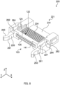
- optical connector
- optical
- regulation
- inward
- outward
- Prior art date
- Legal status (The legal status is an assumption and is not a legal conclusion. Google has not performed a legal analysis and makes no representation as to the accuracy of the status listed.)
- Pending
Links
Images















Classifications
-
- G—PHYSICS
- G02—OPTICS
- G02B—OPTICAL ELEMENTS, SYSTEMS OR APPARATUS
- G02B6/00—Light guides; Structural details of arrangements comprising light guides and other optical elements, e.g. couplings
- G02B6/24—Coupling light guides
- G02B6/36—Mechanical coupling means
- G02B6/38—Mechanical coupling means having fibre to fibre mating means
- G02B6/3807—Dismountable connectors, i.e. comprising plugs
- G02B6/381—Dismountable connectors, i.e. comprising plugs of the ferrule type, e.g. fibre ends embedded in ferrules, connecting a pair of fibres
- G02B6/3826—Dismountable connectors, i.e. comprising plugs of the ferrule type, e.g. fibre ends embedded in ferrules, connecting a pair of fibres characterised by form or shape
- G02B6/383—Hermaphroditic connectors, i.e. two identical plugs mating with one another, each plug having both male and female diametrically opposed engaging parts
-
- G—PHYSICS
- G02—OPTICS
- G02B—OPTICAL ELEMENTS, SYSTEMS OR APPARATUS
- G02B6/00—Light guides; Structural details of arrangements comprising light guides and other optical elements, e.g. couplings
- G02B6/24—Coupling light guides
- G02B6/36—Mechanical coupling means
- G02B6/38—Mechanical coupling means having fibre to fibre mating means
- G02B6/3807—Dismountable connectors, i.e. comprising plugs
- G02B6/3833—Details of mounting fibres in ferrules; Assembly methods; Manufacture
- G02B6/3834—Means for centering or aligning the light guide within the ferrule
- G02B6/3838—Means for centering or aligning the light guide within the ferrule using grooves for light guides
- G02B6/3839—Means for centering or aligning the light guide within the ferrule using grooves for light guides for a plurality of light guides
-
- G—PHYSICS
- G02—OPTICS
- G02B—OPTICAL ELEMENTS, SYSTEMS OR APPARATUS
- G02B6/00—Light guides; Structural details of arrangements comprising light guides and other optical elements, e.g. couplings
- G02B6/24—Coupling light guides
- G02B6/36—Mechanical coupling means
- G02B6/38—Mechanical coupling means having fibre to fibre mating means
- G02B6/3807—Dismountable connectors, i.e. comprising plugs
- G02B6/3873—Connectors using guide surfaces for aligning ferrule ends, e.g. tubes, sleeves, V-grooves, rods, pins, balls
- G02B6/3885—Multicore or multichannel optical connectors, i.e. one single ferrule containing more than one fibre, e.g. ribbon type
-
- G—PHYSICS
- G02—OPTICS
- G02B—OPTICAL ELEMENTS, SYSTEMS OR APPARATUS
- G02B6/00—Light guides; Structural details of arrangements comprising light guides and other optical elements, e.g. couplings
- G02B6/24—Coupling light guides
- G02B6/36—Mechanical coupling means
- G02B6/40—Mechanical coupling means having fibre bundle mating means
- G02B6/403—Mechanical coupling means having fibre bundle mating means of the ferrule type, connecting a pair of ferrules
-
- G—PHYSICS
- G02—OPTICS
- G02B—OPTICAL ELEMENTS, SYSTEMS OR APPARATUS
- G02B6/00—Light guides; Structural details of arrangements comprising light guides and other optical elements, e.g. couplings
- G02B6/24—Coupling light guides
- G02B6/36—Mechanical coupling means
- G02B6/38—Mechanical coupling means having fibre to fibre mating means
- G02B6/3807—Dismountable connectors, i.e. comprising plugs
- G02B6/3833—Details of mounting fibres in ferrules; Assembly methods; Manufacture
- G02B6/3853—Lens inside the ferrule
Definitions
- the present invention relates to an optical connector and an optical connector module.
- PTL 1 discloses a connector system for optically coupling a multiple core fiber and a single core fiber.
- the connector system disclosed in PTL 1 includes a first ferrule for holding an end portion of the multiple core fiber, a second ferrule for holding an end portion of the single core fiber, and a guide pin for connecting the first ferrule and the second ferrule.
- An insertion hole for inserting a guide pin is formed in each of the first ferrule and the second ferrule.
- the multiple core fiber and the single core fiber are optically coupled by connecting the first ferrule and the second ferrule by inserting the guide pins to the insertion holes facing each other in the state where the first ferrule and the second ferrule face each other.
- the guide pin is required to connect the first ferrule and the second ferrule, which makes the operation complicated and increases the cost due to the increased number of components.
- An object of the present invention is to provide an optical connector that can couple optical connectors with the same shape without increasing the number of components, and to provide an optical connector module including the optical connector.
- optical connectors with the same shape can be coupled without increasing the number of components.
- FIG. 1 is a sectional view illustrating a configuration of optical connector module 100 according to Embodiment 1 of the present invention.
- optical connector module 100 includes optical transmission member 110, and optical connector 120.
- Optical connector module 100 is used with a plurality of optical transmission members 110 held by optical connector 120.
- Optical connector module 100 is used as one pair (a pair).
- the plurality of optical transmission members 110 are optically coupled to each other by connecting the same optical connectors 120 to each other in the state where the other optical connector module 100 holding the other plurality of optical transmission members 110 is upside-down with respect to one optical connector module 100 holding the plurality of optical transmission members 110.
- optical connector module 100 may be used together with a housing, a spring clamp structure part and the like (omitted in the drawing).
- optical transmission member 110 is not limited. Examples of the type of optical transmission member 110 include optical fibers and optical waveguides.
- optical transmission member 110 is an optical fiber.
- the optical fiber may be of a single mode type, or a multiple mode type.
- the end surface of optical transmission member 110 is tilted with respect to a plane orthogonal to the extending direction of optical transmission member 110. In the present embodiment, the inclination angle to the plane is 5 degrees.
- the number of optical transmission members 110 is not limited as long as a plurality of optical transmission members 110 is provided. In the present embodiment, 16 optical transmission members 110 are provided.
- the end portion of optical transmission member 110 is fixed to optical connector 120. Note that in the case where an optical waveguide is used as optical transmission member 110, the structure of the holding part in optical connector 120 described later differs (Embodiment 11).
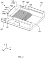
- FIG. 2 is a perspective view as viewed from the upper side of optical connector 120 from which lid 132 is detached according to Embodiment 1 of the present invention.
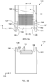
- FIG. 3A is a plan view of optical connector 120 from which lid 132 is detached according to Embodiment 1 of the present invention, and FIG. 3B is a bottom view.
- FIG. 4A is a front view of optical connector 120 according to Embodiment 1 of the present invention, FIG. 4B is a rear view, FIG. 4C is a left side view, and FIG. 4D is a right side view.
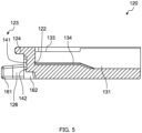
- FIG. 5 is a sectional view taken along line A-A of FIG. 3A .
- first direction the direction in which optical transmission members 110 are disposed in parallel
- second direction the direction orthogonal to the X direction in front view of second optical part 123 (as viewed in the direction along the optical path between two optical connectors 120)
- second direction the direction orthogonal to the X direction and the Z direction
- third direction the direction orthogonal to the X direction and the Z direction
- optical connector 120 is a member with a substantially cuboid shape.
- Optical connector 120 includes holding part 121, first optical part 122, second optical part 123, protrusion 124, recess 125, first inward regulation surface 126, and first outward regulation surface 127.
- the fitting shape is a shape required for achieving the fitting.
- the fitting shape is provided at a contact portion of the engagement of the optical connector and the other optical connector, for example.
- first optical part 122, second optical part 123, protrusion 124 and recess 125, first inward regulation surface 126, and first outward regulation surface 127 have fitting shapes.
- Optical connector 120 is formed of a material that is optically transparent to light with wavelengths used for optical communications.
- the examples of the material of optical connector 120 include polyetherimide (PEI) such as ULTEM (registered trademark) and transparent resins such as cyclic olefin resins.
- PKI polyetherimide
- ULTEM registered trademark
- transparent resins such as cyclic olefin resins.
- optical connector 120 may be manufactured by injection molding, for example.
- Holding part 121 holds the end portions of the plurality of optical transmission members 110.
- the configuration of holding part 121 is not limited as long as the end portions of the plurality of optical transmission members 110 can be held at an appropriate position.
- Holding part 121 may be configured to hold the end portion of optical transmission member 110 by pushing it, or configured to hold the end portion of optical transmission member 110 with the end portion inserted thereto (see Embodiment 2).
- holding part 121 holds the end portion of optical transmission member 110 by pushing it.
- holding part 121 includes holding recess 131, and lid 132 (see FIG. 4B ). Holding recess 131 is open at the top surface and the back surface of optical connector 120.
- the plan shape of holding recess 131 is not limited as long as the end portions of the plurality of optical transmission members 110 can be disposed at an appropriate position.
- the plan shape of holding recess 131 is a rectangular shape.
- Notch part 133 for disposing lid 132 at a predetermined position is disposed at both end portions of holding recess 131 in the first direction (the X direction). In this manner, deviation of installed lid 132 in the third direction (the Y direction) can be prevented.
- a plurality of grooves 134 defined in an irregular shape is disposed at the bottom surface of holding recess 131.
- the irregular shape may be composed of a plurality of ridges, or a plurality of valleys.
- a plurality of grooves 134 defined by a plurality of valleys is disposed at the bottom surface of holding recess 131.
- groove 134 is configured to hold each of a plurality of optical transmission members with peeled tip-end coating of the ribbon-shaped optical transmission member.
- the arrangement of the plurality of grooves 134 is not limited as long as the end portions of the plurality of optical transmission members 110 can be appropriately positioned.
- the plurality of grooves 134 may be disposed in the entire bottom surface of holding recess 131, or in a part of the bottom surface of holding recess 131. In the present embodiment, groove 134 is disposed in a part of the region on first optical part 122 side in the bottom surface of holding recess 131.
- the number of grooves 134 needs only to be equal to or greater than the number of optical transmission members 110 installed. Specifically, in the present embodiment, 16 grooves 134 are provided.
- the cross-sectional shape of groove 134 in the XZ cross-section is not limited. Groove 134 may be a V-shaped groove, or a U-shaped groove. In the present embodiment, groove 134 is a V-shaped groove.
- the depth of groove 134 is a depth with which the upper end portion of optical transmission member 110 is located above the upper end portion of groove 134 (ridge) when optical transmission member 110 is disposed in groove 134. In this manner, drop off of optical transmission member 110 can be prevented by pressing optical transmission member 110 against groove 134 by means of lid 132 described later.
- Groove 134 may be disposed parallel to the rear surface of optical connector 120, or may be disposed such that it comes closer to the rear surface of optical connector 120 with decreasing distance to first optical part 122. In the present embodiment, the valley of groove 134 is disposed parallel to the rear surface of optical connector 120.
- Lid 132 presses the plurality of optical transmission members 110 against groove 134.
- lid 132 presses the plurality of optical transmission members 110 against the optical connector body including holding recess 131, first optical part 122, second optical part 123, a pair of protrusion 124 and recess 125, first inward regulation surface 126, and a pair of first outward regulation surfaces 127.
- Lid 132 is disposed to cover holding recess 131 where the end portion of optical transmission member 110 is disposed.
- the configuration of lid 132 is not limited as long as the above-mentioned function can be ensured.
- the surface of lid 132 on the optical transmission member side may be a flat surface or may be provided with grooves corresponding to the plurality of optical transmission members.
- lid 132 includes lid body 135, and protrusion part 136.
- Lid body 135 covers holding recess 131 from the front surface side of optical connector 120.
- Protrusion part 136 is disposed at both end portions of lid body 135 in the first direction (the X direction), and protruded to the rear side.
- the shape of protrusion part 136 is complementary to the shape of notch part 133 disposed in holding recess 131.
- the end portions of the plurality of optical transmission members 110 are disposed on the plurality of grooves 134, and the end surfaces of the plurality of optical transmission members 110 are brought into contact with first optical part 122.
- adhesive is applied between the end surface of optical transmission member 110 and first optical part 122 with no air layer interposed therebetween.
- the end portions of the plurality of optical transmission members 110 are pressed with lid 132 against the bottom surface (connector body) of holding recess 131.
- optical transmission member 110 can be fixed to optical connector 120. Note that the end surfaces of the plurality of optical transmission members 110 may not be brought into contact with the first optical part.
- First optical part 122 is disposed to face the end surfaces of the plurality of optical transmission members 110 held by holding part 121. First optical part 122 allows incidence of light emitted from the plurality of optical transmission members 110, or emits light toward the end surfaces of the plurality of optical transmission members 110.
- the shape of first optical part 122 is not limited as long as the above-mentioned function can be ensured.
- First optical part 122 may include one or a plurality of projecting surfaces, or may be a flat surface. In the present embodiment, first optical part 122 is a flat surface. First optical part 122 is disposed in a part of the inner surface of holding recess 131.
- first optical part 122 that makes contact with the end surface of optical transmission member 110 may be tilted toward second optical part 123 with decreasing distance to the rear surface of optical connector 120, or may be tilted away from second optical part 123 with decreasing distance to the rear surface of optical connector 120. It may be perpendicular to the rear surface of optical connector 120.
- the surface of first optical part 122 that makes contact with the end surface of optical transmission member 110 is tilted toward second optical part 123 with decreasing distance to the rear surface of optical connector 120 (see FIG. 5 ).
- the inclination angle of first optical part 122 is the same as the inclination angle of the end surface of optical transmission member 110.
- the inclination angle of first optical part 122 is within a range of 3 to 8 degrees, preferably 5 to 8 degrees. In the present embodiment, with respect to the Z direction set as 0 degree, the inclination angle of first optical part 122 is 5 degrees.
- Second optical part 123 emits, to the outside, light entered from first optical part 122, or allows incidence of light from the other optical connector 120.
- the shape of second optical part 123 is not limited as long as the above-mentioned function can be ensured.
- Second optical part 123 may include a plurality of projecting surfaces, or may be a flat surface.
- second optical part 123 includes a plurality of projecting surfaces 141 that can focus light emitted from the optical transmission members. Projecting surfaces 141, which are disposed in parallel in the first direction (the X direction), emit light entered from first optical part 122 toward the other optical connector 120, or allow incidence of light from the other optical connector 120.
- the fitting shapes are the same, while the shape of second optical part 123 is not limited. In the case of a projecting surface, it is preferable that the shapes be the same. Second optical part 123 is disposed at the front surface of optical connector 120.
- the plan shape of projecting surface 141 is not limited.
- the plan shape of projecting surface 141 may be a circular shape, or a rectangular shape. In the present embodiment, the plan shape of projecting surface 141 has a circular shape.
- the number of projecting surfaces 141 is the same as the number of optical transmission members 110. Specifically, in the present embodiment, 16 projecting surfaces 141 are provided.
- second optical part 123 In front view of second optical part 123 (as viewed along an optical path between optical connector 120 and the other optical connector 120), a pair of protrusions 124 and a pair of recesses 125 are disposed at line-symmetric positions with respect to the reference straight line parallel to the first direction (the X direction).
- protrusion 124 and recess 125 are disposed with second optical part 123 therebetween in the second direction (the Z direction) orthogonal to the first direction (the X direction).
- contact surface 142 where second optical part 123, protrusion 124 and recess 125 are not disposed is a flat surface.
- Contact surface 142 makes contact with contact surface 142 of the other optical connector 120.
- Contact surface 142 may be disposed perpendicularly to the rear surface of optical connector 120, or may be tilted with respect to the rear surface of optical connector 120. In the present embodiment, contact surface 142 is disposed perpendicularly to the rear surface of optical connector 120.
- Protrusion 124 has a shape that can engage with recess 125 of the other optical connector 120.
- protrusion 124 is disposed on the front side (upper side) at the front surface of optical connector 120.
- the shape of protrusion 124 is not limited as long as the positional displacement of optical connector 120 in the second direction (the Z direction) can be suppressed.
- the shape of protrusion 124 is a ridge that is wide in the first direction (the X direction).
- protrusion 124 includes second outward regulation surface 143. Note that in the case where recess 125 includes second outward regulation surface 143, it is preferable that protrusion 124 include second inward regulation surface 151.
- protrusion 124 includes second outward regulation surface 143, first surface 144 disposed on the side opposite to second outward regulation surface 143, second surface 145 and third surface 146 disposed facing each other, and top surface 147.
- Second outward regulation surface 143 includes a flat surface disposed to face outward in the second direction (the Z direction). With a flat surface, rather than a curved surface, second outward regulation surface 143 can suppress the positional displacement in the second direction with respect to the other optical connector 120.
- One or a plurality of second outward regulation surfaces 143 may be provided. In the present embodiment, one second outward regulation surface 143 is provided. Second outward regulation surface 143 and first surface 144 are disposed along the first direction (the X direction), and second surface 145 and third surface 146 are disposed along the third direction (the Y direction). In addition, in the present embodiment, first surface 144 is disposed such that it is flush with the front surface of (top surface) optical connector 120.
- Second surface 145 and third surface 146 may be disposed in contact with second inner surface 153 and third inner surface 154 of recess 125 in the other optical connector 120.
- second outward regulation surface 143 and first surface 144 are flat surfaces
- second surface 145, third surface 146 and top surface 147 are curved surfaces.
- Recess 125 has a shape that can engage with protrusion 124 of the other optical connector 120.
- recess 125 is disposed on the rear side (lower side) at the front surface of optical connector 120.
- the shape of recess 125 is not limited as long as the positional displacement of optical connector 120 in the second direction can be suppressed.
- recess 125 is open at the front surface and bottom surface of optical connector 120.
- recess 125 includes second inward regulation surface 151.
- protrusion 124 includes second inward regulation surface 151
- recess 125 include second outward regulation surface 143.
- recess 125 includes second inward regulation surface 151 on the front side, first inner surface 152 on the back side, and second inner surface 153 and third inner surface 154 on the lateral side.
- Second inward regulation surface 151 includes a flat surface disposed to face inward in the second direction (the Z direction) perpendicular to the first direction (the X direction) as viewed along the optical path between optical connector 120 and the other optical connector 120. With a flat surface rather than a curved surface in this manner, second inward regulation surface 151 can suppress the positional displacement in the second direction with respect to the other optical connector 120. Second inward regulation surface 151 is disposed in contact with second outward regulation surface 143 of the other optical connector 120. Second inner surface 153 and third inner surface 154 may be disposed in contact with second surface 145 and third surface 146 of protrusion 124 in the other optical connector 120.
- protrusion 124 is disposed on the front surface side of second optical part 123
- recess 125 is disposed on the rear surface side of second optical part 123, but they may be disposed in the opposite manner.
- recess 125 may be disposed on the front surface side of second optical part 123
- protrusion 124 may be disposed on the rear surface side of second optical part 123.
- protrusion 124 and recess 125 may have complementary shapes.
- protrusion 124 and recess 125 may be disposed in a line-symmetric manner with respect to a virtual line passing through the center in the front-to-back direction and extending in the first direction (the X direction) in front view of optical connector 120.
- First inward regulation surface 126 is a flat surface disposed to face inward along the first direction (the X direction). In the present invention, with such a flat surface rather than a curved surface, first inward regulation surface 126 can suppress the positional displacement in the first direction (the X direction) with respect to the other optical connector 120.
- the number of first inward regulation surface 126 is not limited. In the present embodiment, two (a pair of) first inward regulation surfaces 126 are provided.
- first inward regulation surface 126 is a part of the outer surface of engaging protrusion 161 disposed with second optical part 123 therebetween in the first direction (the X direction).
- Engaging protrusion 161 has a rectangular columnar shape disposed at both end portions of optical connector 120 in the first direction (the X direction) and on the rear surface side, and protruded from the front surface of optical connector 120.
- the inner flat surface of engaging protrusion 161 is first inward regulation surface 126.
- the pair of engaging protrusions 161 is disposed in a line-symmetric manner with respect to a virtual line passing through the center in the horizontal direction and extending in the second direction (the Y direction).
- Engaging recess 162 is a recess that is open at both end portions in the first direction (the X direction), and at corners on the front surface (top surface) side.
- the inner flat surface of engaging recess 162 is first outward regulation surface 127.
- the pair of engaging recesses 162 is disposed in a line-symmetric manner with respect to a virtual line passing through the center in the horizontal direction and extending in the second direction.
- At least a pair of first inward regulation surfaces 126 makes contact with a pair of first outward regulation surfaces 127 of the other optical connector 120, and at least a pair of first outward regulation surfaces 127 makes contact with at least a pair of first inward regulation surfaces 126 of the other optical connector 120, thus regulating the position in the first direction (the X direction).
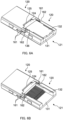
- FIGS. 6A and 6B are perspective views illustrating a state where optical connector modules 100 are connected to each other. Note that in FIGS. 6A and 6B , optical transmission member 110 is omitted.
- one optical connector module 100 is set with lid 132 facing the upper side, and the other optical connector module 100 is rotated (turned upside down) with a straight line along the first direction (the X direction) as a rotation axis. Further, protrusion 124 of one optical connector module 100 and recess 125 of the other optical connector module 100 are engaged with each other, and recess 125 of one optical connector module 100 and protrusion 124 of the other optical connector module 100 are engaged with each other. This regulates the positional displacement between one optical connector module 100 and the other optical connector module 100 in the second direction (the Z direction).
- engaging protrusion 161 of one optical connector module 100 and engaging recess 162 of the other optical connector module 100 are engaged with each other, and engaging recess 162 of one optical connector module 100 and engaging protrusion 161 of the other optical connector module 100 are engaged with each other.
- FIG. 7 is a diagram illustrating optical paths between one optical connector module 100 and the other optical connector module 100.
- one optical transmission member 110 and the other optical transmission member 110 are disposed on substantially the same straight line.
- Light emitted from one optical transmission member 110 substantially horizontally travels, and enters optical connector 120 of first optical part 122.
- Light having entered optical connector 120 is emitted from projecting surface 141 of second optical part 123.
- Light emitted from one optical connector module 100 is entered from projecting surface 141 of second optical part 123 of the other optical connector module 100.
- Light having entered optical connector 120 is emitted from first optical part 122 and enters optical transmission member 110 fixed to the other optical connector module 100.
- optical connector modules 100 when optical connector modules 100 according to the present embodiment are connected to each other, light emitted from optical transmission member 110 of one optical connector module 100 travels substantially straight, and reaches optical transmission member 110 of the other optical connector module 100.
- the central axis of one projecting surface 141 of the plurality of projecting surfaces 141, and a virtual line passing through the center the end surface of one optical transmission member 110 corresponding to one projecting surface 141 of the plurality of optical transmission members 110 and extending along the third direction perpendicular to the first direction (the X direction) and the second direction be not intersect with the reference straight line.
- optical connectors 120 With the central axis of projecting surface 141, the central axis of optical transmission member 110, and the virtual line that do not coincide with each other, two optical connectors 120 with the same shape can be engaged with each other. If the central axis of optical transmission member 110 and the virtual line coincide with each other, light emitted from optical transmission member 110 of one optical connector module 100 cannot appropriately reach optical transmission member 110 of the other optical connector module 100.
- optical connector module 100 of the present embodiment the positional displacement in the first direction (the X direction) can be suppressed with the pair of first inward regulation surfaces 126 and the pair of first outward regulation surfaces 127.
- two optical connectors 120 with the same shape can be engaged with each other without increasing the number of components.
- optical connector module according to a modification of Embodiment 1 is described.
- the optical connector module according to the modification is different from optical connector module 100 according to Embodiment 1 only in the configuration of optical connector 220.
- optical connector 220 is mainly described below.
- FIG. 8 is a perspective view as viewed from the upper side of optical connector 220 from which lid 132 is detached according to a modification of Embodiment 1 of the present invention.
- optical connector 220 includes holding part 221, first optical part 122, second optical part 123, protrusion 124, recess 125, first inward regulation surface 226, and first outward regulation surface 227.
- Holding part 221 of the present modification includes holding recess 231 and lid 132.
- a plurality of grooves 234 is composed of a plurality of ridges at the bottom surface of holding recess 231.
- groove 234 is disposed in a part of the region on the first optical part 122 side in the bottom surface of holding recess 131.
- the number of grooves 234 is the same as the number of optical transmission member 110. Specifically, in the present embodiment, 16 grooves 234 are provided.
- groove 234 is a V-shaped groove.
- the depth of groove 234 is a depth with which the upper end portion of optical transmission member 110 is located above the upper end portion of groove 234 (ridge) in the state where optical transmission member 110 is disposed in groove 234.
- groove 234 is disposed such that it comes closer to second optical part 123 with decreasing distance to the rear surface of optical connector 220.
- First inward regulation surface 226 is a flat surface of a part of engaging protrusion 261
- first outward regulation surface 227 is a flat surface of a part of engaging recess 262.
- Engaging protrusion 261 and engaging recess 262 make up a latch structure.
- Engaging protrusion 261 includes first engaging portion 263 for engaging with second engaging portion 264 of engaging recess 262 of the other optical connector 220.
- Engaging recess 262 includes second engaging portion 264 for engaging with first engaging portion 263 of engaging protrusion 261 of the other optical connector 220.
- the optical connector module according to the present modification has the same effects as those of Embodiment 1.
- the optical connector module according to the present modification can easily couple and release optical connectors 220 with the same shape.
- optical connector module according to Embodiment 2 is described.
- the optical connector module according to Embodiment 2 is different from optical connector module 100 according to Embodiment 1 only in the configuration of optical connector 320.
- optical connector 320 is mainly described below.
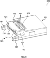
- FIG. 9 is perspective view of optical connector 320 according to Embodiment 2 of the present invention.
- FIG. 10A is a plan view of optical connector 320 according to Embodiment 2 of the present invention, and FIG. 10B is a bottom view.
- FIG. 11A is a front view of optical connector 320 according to Embodiment 2 of the present invention, FIG. 11B is a rear view, FIG. 11C is a left side view, and FIG. 11D is a right side view.
- FIG. 12 is a sectional view taken along line A-A of FIG. 10A .
- optical connector 320 includes holding part 321, first optical part 122, second optical part 123, protrusion 124, recess 125, first inward regulation surface 126, and first outward regulation surface 127.
- Holding part 321 holds optical transmission member 110.
- holding part 321 includes insertion part 371, a plurality of through holes 372, and adhesive recess 373.
- Insertion part 371 is for inserting the plurality of optical transmission members 110. Insertion part 371 is open at the back surface of optical connector 320, with a size that enables insertion of the plurality of optical transmission members 110.
- the plurality of through holes 372 is formed at the bottom portion of insertion part 371. Insertion part 371 sets optical transmission member 110 such that optical transmission member 110 is parallel to the rear surface of optical connector 320.
- the plurality of through holes 372 sets the plurality of optical transmission members 110 at a predetermined interval. It suffices that through hole 372 has a size with which optical transmission member 110 can be inserted.
- One side of through hole 372 is open at insertion part 371, and the other side is open at adhesive recess 373.
- Adhesive is injected to adhesive recess 373 to fix optical transmission member 110 to first optical part 122.
- a part of the inner surface of adhesive recess 373 is first optical part 122.
- through hole 372 is open at the inner surface facing first optical part 122.
- optical connector 320 In optical connector 320 according to Embodiment 2, the end portion of optical transmission member 110 is inserted from insertion part 371 and passed through hole 372, and the end surface of optical transmission member 110 is brought into contact with first optical part 122. Next, optical transmission member 110 is fixed to optical connector 320 by injecting adhesive from adhesive recess 373 and curing the adhesive. Finally, optical connectors 320 are coupled with each other with the other optical connector 320 turned upside-down with respect to one optical connector 320. In this manner, optical transmission members 110 are optically coupled with each other.
- the optical connector module according to Embodiment 2 has the same effects as those of Embodiment 1.
- the optical connector module according to Embodiment 2 does not include lid 132, the number of components can be further reduced, and the cost can be reduced.
- the optical connector module according to a reference example of Embodiment 1 is described.
- the shapes of one optical connector 120 and the other optical connector 520 are different from each other.
- the configuration of one optical connector 120 is the same as that of optical connector 120 according to Embodiment 1. Therefore, mainly the other optical connector 520 is described below.
- the other optical connector 520 of the reference example is different from optical connector 120 according to Embodiment 1 in that fixing part 528 for the substrate is provided.
- the same components as those of optical connector 120 according to Embodiment 1 are denoted with the same reference numerals and the description thereof will be omitted.
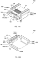
- FIG. 13A is a perspective view as viewed from the upper side of optical connector 520 from which a lid is detached according to the reference example
- FIG. 13B is a perspective view as viewed from the lower side
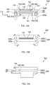
- FIG. 14A is a plan view of optical connector 520 from which the lid is detached according to the reference example
- FIG. 14B is a bottom view
- FIG. 15A is a front view of optical connector 520 from which the lid is detached according to the reference example
- FIG. 15B is a rear view
- FIG. 15C is a right side view.
- the other optical connector 520 includes holding part 121, first optical part 122, second optical part 123, protrusion 124 and recess 125, first inward regulation surface 126, first outward regulation surface 127, and fixing part 528.
- Holding part 121, first optical part 122, second optical part 123, protrusion 124, recess 125, first inward regulation surface 126, and first outward regulation surface 127 are the same as the components of Embodiment 1, and therefore the description thereof will be omitted.
- Fixing part 528 includes claw part 528a and nob 528b.
- Claw part 528a engages with substrate 600 to fix optical connector 520 to substrate 600.
- the number of claw parts 528a is not limited. In the present embodiment, two (a pair of) claw parts 528a are provided.
- claw part 528a protrudes to the lower side (the Z direction) than the bottom surface of optical connector 520.
- claw part 528a is disposed along the third direction (the Y direction) at both end portions of optical connector 520 in the first direction (the X direction).
- Claw part 528a is inserted to through hole 601 formed in substrate 600 from one surface of substrate 600. When claw part 528a is engaged with substrate 600 (through hole 601), optical connector 520 is fixed to substrate 600.
- Nob 528b is used for releasing substrate 600 and optical connector 520.
- the number of nobs 528b is not limited. In the present embodiment, two (a pair of) nobs 528b are provided. In addition, in the present embodiment, nob 528b protrudes to the upper side (the Z direction) than the top surface of optical connector 520. In addition, nob 528b is disposed along the third direction (the Y direction) at both end portions of optical connector 520 in the first direction (the X direction). Claw part 528a and nob 528b are formed as one piece, and the boundary portion between claw part 528a and nob 528b is connected to the connector body. This boundary portion functions as a fulcrum for moving claw part 528a when nob 528b is moved. Specifically, in the present embodiment, nob 528b is disposed on the side opposite to claw part 528a.
- nob 528b is tilted inward.
- claw part 528a is tilted such that the tip end portion of claw part 528a moves outward.
- optical connector 520 can be inserted to or detached from through hole 601 of substrate 600.
- FIG. 16A is a perspective view for describing usage of connector 520
- FIG. 16B is a side view for describing usage of connector 520.
- optical connector 520 of the other optical connector module is fixed to substrate 600 by inserting claw part 528a to through hole 601 of substrate 600 while expanding claw part 528a by pinching the pair of nobs 528b, and then releasing the force applied to the pair of nobs 528b, with lid 132 facing the upper side.
- One optical connector module 100 is connected to optical connector 520 of the other optical connector module in an upside-down manner. At this time, protrusion 124 of the other optical connector module and recess 125 of one optical connector module 100 are engaged with each other, and recess 125 of the other optical connector module and protrusion 124 of one optical connector module 100 are engaged with each other.
- the positional displacement between the other optical connector module and one optical connector module 100 is regulated.
- engaging protrusion 161 of the other optical connector module and engaging recess 162 of one optical connector module 100 are engaged with each other, and engaging recess 162 of the other optical connector module and engaging protrusion 161 of one optical connector module 100 are engaged with each other.
- the positional displacement between the other optical connector module and one optical connector module 100 is regulated.
- the plurality of optical transmission members 110 connected to the other optical connector module and optical transmission member 110 connected to one optical connector module 100 are optically connected to each other.
- the optical connector module of the present embodiment can fix the other optical connector 520 to the substrate without using other components while achieving the effects of Embodiment 1, and thus the other optical connector 520 can be densely installed on substrate 600.
- the height (the Z direction) of the connecting part of one connector 120 and the other connector 520 can be reduced, and thus the generated heat can be easily dissipated.
- optical connector module 600 according to Embodiment 3 is described.
- Optical connector module 600 according to Embodiment 3 is different from optical connector module 100 according to Embodiment 1 only in the configuration of optical connector 620.
- optical connector 620 is mainly described below.
- Optical connector 620 according to the present embodiment can suppress the damage to protrusion 124 even when a stress is applied from the second direction (the Z direction).
- FIG. 17 is a perspective view of optical connector 620 according to Embodiment 3 of the present invention as viewed from the lower side.
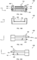
- FIG. 18A is a plan view of optical connector 620 according to Embodiment 3 of the present invention, and FIG. 18B is a bottom view.
- FIG. 19A is a front view of optical connector 620 according to Embodiment 3 of the present invention, FIG. 19B is a rear view, FIG. 19C is a left side view, and FIG. 19D is a right side view.
- optical connector 620 includes holding part 621, first optical part 122, second optical part 123, protrusion 124, recess 125, first inward regulation surface 126, and first outward regulation surface 127.
- Holding part 621 holds the end portions of the plurality of optical transmission members 110. In the present embodiment, holding part 621 holds the end portion of optical transmission member 110 by pushing it. In the present embodiment, holding part 621 includes holding recess 631 and lid 632 (see FIG. 20 ). Holding recess 631 is open at the top surface and back surface of optical connector 620. In the present embodiment, holding recess 631 has a rectangular plan shape. Note that in the present embodiment, the notch part for disposing lid 632 at a predetermined position is not disposed at both end portions of holding recess 631 in the first direction (the X direction).
- contact surface 642 where second optical part 123, protrusion 124 and recess 125 are not disposed is a flat surface.
- Contact surface 642 makes contact with contact surface 642 of the other optical connector 620.
- contact surface 642 is tilted with respect to the rear surface of optical connector 620. More specifically, as viewed along the first direction (the X direction), contact surface 642 is a tilted surface tilted toward first optical part 122 side as it goes from protrusion 124 toward recess 125.
- one optical connector module 600 is connected to optical connector 620 of the other optical connector module 600 in an upside-down manner.
- protrusion 124 of the other optical connector module 600 and recess 125 of one optical connector module 600 are engaged with each other, and recess 125 of the other optical connector module 600 and protrusion 124 of one optical connector module 600 are engaged with each other.
- the positional displacement between the other optical connector module 600 and one optical connector module 600 is regulated.
- engaging protrusion 161 of the other optical connector module 600 and engaging recess 162 of one optical connector module 600 are engaged with each other, and engaging recess 162 of the other optical connector module and engaging protrusion 161 of one optical connector module 600 are engaged with each other.
- the positional displacement between the other optical connector module 600 and one optical connector module 600 is regulated.
- contact surface 642 of one optical connector module 600 and contact surface 642 of the other optical connector module 600 are brought into contact with each other. In this manner, the plurality of optical transmission members 110 connected to the other optical connector module 600 and optical transmission member 110 connected to one optical connector module 600 are optically connected to each other.
- Optical connector module 600 of the present embodiment has the same effects as those of optical connector module 100 according to Embodiment 1.
- optical connector module 600 of the present embodiment can suppress the damage to protrusion 124 even when a stress is applied along the second direction (the Z direction).
- FIG. 21 is a perspective view of optical connector 720 according to Embodiment 4 of the present invention as viewed from the lower side.
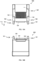
- FIG. 22A is a plan view of optical connector 720 according to Embodiment 4 of the present invention, and FIG. 22B is a bottom view.
- FIG. 23A is a front view of optical connector 720 according to Embodiment 4 of the present invention, FIG. 23B is a rear view, FIG. 23C is a left side view, and FIG. 23D is a right side view.
- Holding part 621 is the same as optical connector 620 according to Embodiment 3, and the notch part for disposing the lid 632 at a predetermined position is not disposed at both end portions of holding recess 631 in the first direction (the X direction).
- contact surface 142 where second optical part 123, protrusion 724 and recess 725 are not disposed is a flat surface that is disposed perpendicularly to the rear surface of optical connector 720.
- Second inward regulation surface 751 includes a flat surface disposed to face inward in the second direction (the Z direction). As a flat surface, rather than a curved surface, second inward regulation surface 751 can suppress the positional displacement in the second direction (the Z direction) with respect to the other optical connector 720. In the present embodiment, one second inward regulation surface 751 is provided. In addition, in the present embodiment, second inward regulation surface 751 is a part of the outer surface of protrusion 724 in the Z direction (the second direction).
- First inward regulation surface 726 includes a flat surface disposed to face inward along the first direction (the X direction). As a flat surface rather than a curved surface in this manner, first inward regulation surface 726 can suppress the positional displacement in the first direction (the X direction) with respect to the other optical connector 720. In the present embodiment, two (a pair of) first outward regulation surfaces 727 are provided. In addition, in the present embodiment, first inward regulation surface 726 is a part of the inner surface of recess 725 in the first direction (the X direction).
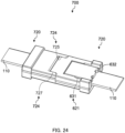
- FIG. 24 is a perspective view for describing usage of optical connector module 700 according to Embodiment 4 of the present invention.
- one optical connector module 700 is connected to optical connector 720 of the other optical connector module 700 in an upside-down manner.
- protrusion 724 of the other optical connector module 700 and recess 725 of one optical connector module 700 are engaged with each other.
- the positional displacement between the other optical connector module 700 and one optical connector module 700 is regulated.
- the plurality of optical transmission members 110 connected to the other optical connector module 700 and optical transmission member 110 connected to one optical connector module 700 are optically connected to each other.
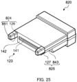
- FIG. 25 is a perspective view of optical connector 820 according to Embodiment 5 of the present invention as viewed from the lower side.
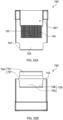
- FIG. 26A is a plan view of optical connector 820 according to Embodiment 5 of the present invention, and FIG. 26B is a bottom view.
- FIG. 27A is a front view of optical connector 820 according to Embodiment 5 of the present invention, FIG. 27B is a rear view, FIG. 27C is a left side view, and FIG. 27D is a right side view.
- Second inward regulation surface 851 includes a flat surface disposed to face inward in the second direction. As a flat surface, rather than a curved surface, second inward regulation surface 851 can suppress the positional displacement in the second direction (the Z direction) with respect to the other optical connector 820. In the present embodiment, two (a pair of) second inward regulation surfaces 851 are provided. In addition, in the present embodiment, second inward regulation surface 851 is a part of the outer surface of protrusion 824 in the Z direction (the second direction).
- Optical connector module 800 of the present embodiment has the same effects as those of optical connector module 100 according to Embodiment 1.
- optical connector module according to Embodiment 6 is described.
- the optical connector module according to Embodiment 6 is different from optical connector module 100 according to Embodiment 1 only in the configuration of optical connector 920.
- optical connector 920 is mainly described below.
- FIG. 29 is a perspective view of optical connector 920 according to Embodiment 6 of the present invention as viewed from the lower side.
- FIG. 30A is a plan view of optical connector 920 according to Embodiment 6 of the present invention, and FIG. 30B is a bottom view.
- FIG. 31A is a front view of optical connector 920 according to Embodiment 6 of the present invention, FIG. 31B is a rear view, FIG. 31C is a left side view, and FIG. 31D is a right side view.
- optical connector 920 includes holding part 621, first optical part 122, second optical part 123, protrusion 924, recess 925, first inward regulation surface 126, and first outward regulation surface 127.
- Holding part 621 is the same as optical connector 620 according to Embodiment 3, and the notch part for disposing the lid 632 at a predetermined position is not disposed at both end portions of holding recess 631 in the first direction (the X direction).
- First inward regulation surface 126 includes a flat surface disposed to face inward along the first direction (the X direction). As a flat surface rather than a curved surface in this manner, first inward regulation surface 126 can suppress the positional displacement in the first direction (the X direction) with respect to the other optical connector 920. In the present embodiment, two (a pair of) first inward regulation surfaces 126 are provided. In addition, in the present embodiment, first inward regulation surface 126 is a part of the outer surface of protrusion 924 in the first direction (the X direction).
- First outward regulation surface 127 includes a flat surface disposed to face outward along the first direction (the X direction). With a flat surface rather than a curved surface in this manner, first outward regulation surface 127 can suppress the positional displacement in the first direction (the X direction) with respect to the other optical connector 920. In the present embodiment, two (a pair of) first outward regulation surfaces 127 are provided. In addition, in the present embodiment, first outward regulation surface 127 is a part of the inner surface of recess 925 in the first direction (the X direction).
- optical connector module according to Embodiment 7 is described.
- the optical connector module according to Embodiment 7 is different from optical connector module 100 according to Embodiment 1 only in the configuration of optical connector 1020.
- optical connector 1020 is mainly described below.
- FIGS. 32A and 32B are perspective views of optical connector 1020 according to Embodiment 7 of the present invention.
- FIG. 32A is a perspective view as viewed from the upper side of optical connector 1020
- FIG. 32B is a perspective view as viewed from the lower side.
- optical connector 1020 includes holding part 621, first optical part 122, second optical part 123, protrusion 124, recess 125, first inward regulation surface 126, first outward regulation surface 127, inward regulation part 1071, and outward regulation part 1074.
- First outward regulation surface 127 includes a flat surface disposed to face outward along the first direction (the X direction). With a flat surface rather than a curved surface in this manner, first outward regulation surface 127 can suppress the positional displacement in the first direction (the X direction) with respect to the other optical connector 1020.
- the number of first outward regulation surfaces 127 is not limited. In the present embodiment, two (a pair of) first outward regulation surfaces 127 are provided.
- first outward regulation surface 127 is a part of the inner surface engaging recess 1062 disposed with second optical part 123 therebetween in the first direction (the X direction).
- Inward regulation part 1071 is disposed with second optical part 123 therebetween in the first direction (the X direction), and disposed to face the direction opposite to the inward direction (outward regulation part 1074) in the second direction (the Z direction) perpendicular to the first direction (the X direction) as viewed along the optical path between optical connector 1020 and the other optical connector 1020, so as to suppress the positional displacement in the second direction (the Z direction) with respect to the other optical connector 1020.
- inward regulation part 1071 includes first flat surface 1072 perpendicular to the second direction (the Z direction), and third flat surface 1073 perpendicular to first flat surface 1072.
- the third flat surface may not be perpendicular to first flat surface 1072, and may be tilted to first flat surface 1072. With such a flat surface in this manner, the positional displacement in the second direction (the Z direction) with respect to the other optical connector 1020 can be suppressed.
- the number of inward regulation part 1071 is not limited. In the present embodiment, two (a pair of) inward regulation parts 1071 are provided. In addition, in the present embodiment, inward regulation part 1071 is an inner surface of a protrusion formed in engaging recess 1062 disposed with second optical part 123 therebetween in the first direction (the X direction).
- Outward regulation part 1074 is disposed to face outward (the direction opposite to inward regulation part 107) with second optical part 123 therebetween in the first direction (the X direction), so as to suppress the positional displacement in the second direction (the Z direction) with respect to the other optical connector 1020.
- Outward regulation part 1074 includes second flat surface 1075 perpendicular to the second direction (the Z direction), and second tilted surface 1076 tilted with respect to second flat surface 1075. With such a flat surface, the positional displacement in the second direction (the Z direction) with respect to the other optical connector 1020 can be suppressed.
- the number of outward regulation parts 1074 is not limited. In the present embodiment, two (a pair of) outward regulation parts 1074 are provided.
- outward regulation part 1074 is an inner surface of a notch part formed at the tip end of engaging protrusion 1061 disposed with second optical part 123 therebetween in the first direction (the X direction).
- a second perpendicular surface may be provided instead of second tilted surface 1076.
- the second perpendicular surface is a surface perpendicular to second flat surface 1075.
- FIGS. 33A to 33C are perspective views illustrating a state where optical connector modules are connected to each other.
- FIG. 33A is a perspective view illustrating a state where optical connector modules are connected to each other
- FIG. 33B is a side view illustrating a state where optical connector modules are connected to each other
- FIG. 33C is a sectional view illustrating a state where optical connector modules are connected to each other. Note that in FIGS. 33A to 33C , the optical transmission member and the lid are omitted.
- a part of one optical connector module inward regulation part 1071 makes contact with outward regulation part 1074 of the other optical connector module 1000, and a part of outward regulation part 1074 of one optical connector module makes contact with inward regulation part 1071 of the other optical connector module 1000.
- second inward regulation surface 151 of one optical connector module makes contact with second outward regulation surface 143 of the other optical connector module 1000, and second outward regulation surface 143 of one optical connector module makes contact with second inward regulation surface 151 of the other optical connector module 1000.
- optical connector module according to Embodiment 8 is described.
- the optical connector module according to Embodiment 8 is different from optical connector module 100 according to Embodiment 1 only in the configuration of optical connector 1120.
- optical connector 1120 is mainly described below.
- FIGS. 34A and 34B are perspective views of optical connector 1120 according to Embodiment 8 of the present invention.
- FIG. 34A is a perspective view as viewed from the upper side of optical connector 1120
- FIG. 34B is a perspective view as viewed from the lower side.
- First inward regulation surface 126 includes a flat surface disposed to face inward along the first direction (the X direction). In the present invention, with such a flat surface rather than a curved surface, first inward regulation surface 126 can suppress the positional displacement in the first direction (the X direction) with respect to the other optical connector 120.
- the number of first inward regulation surfaces 126 is not limited. In the present embodiment, two (a pair of) first inward regulation surfaces 126 are provided.
- first inward regulation surface 126 is a part of the outer surface of engaging protrusion 1161 disposed with second optical part 123 therebetween in the first direction (the X direction).
- third inward regulation surface 1177 is a part of the top surface of engaging protrusion 1161 disposed with second optical part 123 therebetween in the first direction (the X direction), and a part of the inner surface of engaging recess 1162.
- FIGS. 35A to 35C are perspective views illustrating a state where optical connector modules are connected to each other.
- FIG. 35A is a perspective view illustrating a state where optical connector modules are connected to each other
- FIG. 35B is a side view illustrating a state where optical connector modules are connected to each other
- FIG. 35C is a sectional view illustrating a state where optical connector modules are connected to each other. Note that in FIGS. 35A to 35C , optical transmission member 110 and the lid are omitted.
- one optical connector module is set with the lid facing the upper side, and the other optical connector module is rotated (turned upside down) with a straight line along the first direction (the X direction) as a rotation axis. Then, protrusion 124 of one optical connector module and recess 125 of the other optical connector module are engaged with each other, and recess 125 of one optical connector module and protrusion 124 of the other optical connector module are engaged with each other.
- first outward regulation surface 127 of one optical connector module makes contact with first inward regulation surface 126 of the other optical connector module
- first inward regulation surface 126 of one optical connector module makes contact with first outward regulation surface 127 of the other optical connector module.
- third inward regulation surface 1177 of one optical connector module makes contact with third inward regulation surface 1177 of the other optical connector module.
- the positional displacement between one optical connector module and the other optical connector module is regulated, and, in the third direction (the Y direction), the twist between one optical connector module and the other optical connector module is regulated.
- optical connector module of the present embodiment has the same effects as those of optical connector module 100 according to Embodiment 1.
- optical connector module according to Embodiment 9 is described.
- the optical connector module according to Embodiment 9 is different from optical connector module 100 according to Embodiment 1 only in the configuration of optical connector 1220.
- optical connector 1220 is mainly described below.
- optical connector 1220 includes holding part 621, first optical part 122, second optical part 123, protrusion 1224, recess 1225, first inward regulation surface 1226, and first outward regulation surface 1227.
- protrusion 1224 includes second inward regulation surface 1251, and recess 1225 includes second outward regulation surface 1243.
- protrusion 1324 includes second inward regulation surface 1351, and recess 1325 includes second outward regulation surface 1343.
- First inward regulation surface 1326 includes a flat surface disposed to face inward along the first direction (the X direction). In the present invention, with such a flat surface rather than a curved surface, first inward regulation surface 1326 can suppress the positional displacement in the first direction (the X direction) with respect to the other optical connector 1320.
- the number of first inward regulation surfaces 1326 is not limited. In the present embodiment, two (a pair of) first inward regulation surfaces 1326 are provided.
- first inward regulation surface 1326 is a part of the outer surface of engaging protrusion 1361 disposed with second optical part 123 therebetween in the first direction (the X direction). In the present embodiment, first inward regulation surface 1326 is parallel to the YZ plane.
- protrusion 1324 and engaging protrusion 1361 are formed as one piece.
- recess 1325 and engaging recess 1362 are formed as one piece.
- first outward regulation surface 1327 of one optical connector module and first inward regulation surface 1326 of the other optical connector module make contact with each other, and first inward regulation surface 1326 of one optical connector module and first outward regulation surface 1327 of the other optical connector module make contact with each other.
- the positional displacement between one optical connector module and the other optical connector module is regulated.
- the positional displacement is regulated only in one of the third direction (the Y direction), and as such it is preferable to regulate the positional displacement by means of an adapter or the like.
- optical connector module 1400 according to Embodiment 11 optically couples the plurality of optical transmission members 110 and the other optical transmission member 1420 by engaging the optical connector holding the plurality of optical transmission members 110 as optical fibers according to any of one Embodiments 1 to 10, and optical connector 1420 holding optical transmission member 1410 serving as an optical waveguide.
- optical connector 620 according to Embodiment 3 serving as the optical connector holding the plurality of optical transmission members 110 as optical fibers.
- Holding part (installation section) 1421 holds optical transmission member 1410 serving as an optical waveguide.
- the configuration of holding part 1421 is not limited as long as optical transmission member 1410 can be installed.
- holding part 1421 is the entire region on the back side of optical connector 1420 than second optical part 123.
- holding part (installation section) 1421 does not include groove 134 for disposing optical transmission member 1420 as an optical waveguide.
- optical connector module 1400 is described.
- one optical connector module 600 is connected to optical connector 1420 of the other optical connector module 1400 in an upside-down manner.
- protrusion 124 of the other optical connector module 1400 and recess 125 of one optical connector module 600 are engaged with each other, and recess 125 of the other optical connector module 1400 and protrusion 124 of one optical connector module 600 are engaged with each other.
- the positional displacement between the other optical connector module 1400 and one optical connector module 600 is regulated.
- engaging protrusion 161 of the other optical connector module 1400 and engaging recess 162 of one optical connector module 600 are engaged with each other, and engaging recess 162 of the other optical connector module and engaging protrusion 161 of one optical connector module 600 are engaged with each other.
- the positional displacement between the other optical connector module 1400 and one optical connector module 600 is regulated.
- contact surface 642 of one optical connector module 600 and contact surface 642 of the other optical connector module 1400 are brought into contact with each other. In this manner, the plurality of optical transmission members 110 connected to the other optical connector module 1400 and optical transmission member 110 connected to one optical connector module 600 are optically connected to each other.
- Optical connector module 1400 of the present embodiment has the same effects as those of optical connector module 100 according to Embodiment 1.
- optical connector and the optical connector module according to the present invention are suitable for optical communications using optical transmission members.
Landscapes
- Physics & Mathematics (AREA)
- General Physics & Mathematics (AREA)
- Optics & Photonics (AREA)
- Optical Couplings Of Light Guides (AREA)
- Mechanical Coupling Of Light Guides (AREA)
Abstract
Description
- The present invention relates to an optical connector and an optical connector module.
- In the related art, in the field of optical communications of transmitting light emitted from a light-emitting element such as a surface-emitting laser (for example, vertical-cavity surface-emitting laser (VCSEL), a plurality of optical transmission members is used to increase the capacity. Further, an optical connector for optically coupling optical transmission members is known (see, for example, PTL 1).
- PTL 1 discloses a connector system for optically coupling a multiple core fiber and a single core fiber. The connector system disclosed in PTL 1 includes a first ferrule for holding an end portion of the multiple core fiber, a second ferrule for holding an end portion of the single core fiber, and a guide pin for connecting the first ferrule and the second ferrule. An insertion hole for inserting a guide pin is formed in each of the first ferrule and the second ferrule.
- In the connector system disclosed in PTL 1, the multiple core fiber and the single core fiber are optically coupled by connecting the first ferrule and the second ferrule by inserting the guide pins to the insertion holes facing each other in the state where the first ferrule and the second ferrule face each other.
- PTL 1
Japanese Patent Application Laid-Open No. 2020-101738 - However, in the connector system disclosed in PTL 1, the guide pin is required to connect the first ferrule and the second ferrule, which makes the operation complicated and increases the cost due to the increased number of components.
- An object of the present invention is to provide an optical connector that can couple optical connectors with the same shape without increasing the number of components, and to provide an optical connector module including the optical connector.
-
- [1] An optical connector configured to hold a plurality of optical transmission members, and configured to be engaged with another optical connector with a same fitting shape holding a plurality of other optical transmission members to optically couple the plurality of optical transmission members and the plurality of other optical transmission members, the optical connector including: a holding part configured to hold the plurality of optical transmission members disposed in parallel to each other in a first direction; a first optical part disposed to face end surfaces of the plurality of optical transmission members held by the holding part, and configured to allow incidence of light emitted from the plurality of optical transmission members or emit light toward the plurality of optical transmission members; a second optical part configured to emit toward the other optical connector light entered from the first optical part, or allow incidence of light from the other optical connector; a protrusion and a recess disposed at positions in a line-symmetric manner with respect to a reference straight line extending in parallel to the first direction as viewed along an optical path between the optical connector and the other optical connector, the protrusion and the recess being configured for engaging with the other optical connector; at least one pair of first inward regulation surfaces that are flat surfaces disposed to face inward in the first direction, and configured to suppress positional displacement with respect to the other optical connector in the first direction; and at least one pair of first outward regulation surfaces that are flat surfaces disposed to face outward in the first direction, and configured to suppress positional displacement with respect to the other optical connector in the first direction. When the optical connector and the other optical connector are engaged with each other, the protrusion and the recess are engaged with a recess and a protrusion, respectively, of the other optical connector, the at least one pair of first inward regulation surfaces makes contact with at least one pair of first outward regulation surfaces of the other optical connector, and the at least one pair of first outward regulation surfaces makes contact with at least one pair of first inward regulation surfaces of the other optical connector.
- [2] The optical connector according to [1], in which the at least one pair of first inward regulation surfaces and the at least one pair of first outward regulation surfaces are a part of a latch structure configured to connect the optical connector and the other optical connector.
- [3] The optical connector according to [1] or [2], in which one of the protrusion and the recess includes a second inward regulation surface that is a flat surface disposed to face inward in a second direction perpendicular to the first direction as viewed along the optical path between the optical connector and the other optical connector, and configured to suppress positional displacement with respect to the other optical connector in the second direction. The other of the protrusion and the recess includes a second outward regulation surface that is a flat surface disposed to face outward in the second direction, and configured to suppress positional displacement with respect to the other optical connector in the second direction. When the optical connector and the other optical connector are engaged with each other, the second inward regulation surface makes contact with a second outward regulation surface of the other optical connector, and the second outward regulation surface makes contact with a second inward regulation surface of the other optical connector.
- [4] The optical connector according to any one of [1] to [3], further including: an outward regulation part disposed to sandwich the second optical part in the first direction and to face outward in a second direction perpendicular to the first direction as viewed along the optical path between the optical connector and the other optical connector, the outward regulation part being configured to suppress positional displacement with respect to the other optical connector in the second direction; and an inward regulation part disposed to sandwich the second optical part in the first direction and to face away from the outward regulation part as viewed along the optical path between the optical connector and the other optical connector in the second direction, the inward regulation part being configured to suppress positional displacement with respect to the other optical connector in the second direction. The inward regulation part includes a first flat surface perpendicular to the second direction. The outward regulation part includes a second flat surface perpendicular to the second direction, and a second tilted surface tilted with respect to the second surface or a second perpendicular surface perpendicular to the second surface. When the optical connector and the other optical connector are engaged with each other, a part of the inward regulation part makes contact with an outward regulation part of the other optical connector, and a part of the outward regulation part makes contact with an inward regulation part of the other optical connector.
- [5] The optical connector according to any one of [1] to [4], further including a third inward regulation surface that is a flat surface disposed to face the reference straight line in a second direction perpendicular to the first direction as viewed along the optical path between the optical connector and the other optical connector, the third inward regulation surface being configured to suppress positional displacement with respect to the other optical connector in the second direction. The third inward regulation surface makes contact with a third inward regulation surface of the other optical connector.
- [6] The optical connector according to [3], in which the second inward regulation surface and the second outward regulation surface are tilted with respect to the second direction perpendicular to the first direction as viewed along the optical path between the optical connector and the other optical connector.
- [7] The optical connector according to any one of [1] to [6], in which the first inward regulation surface and the first outward regulation surface are tilted with respect to the second direction in a plane including the first direction, and the second direction perpendicular to the first direction as viewed along the optical path between the optical connector and the other optical connector.
- [8] The optical connector according to any one of [1] to [7], in which the holding part includes: a holding recess including a notch part at both end portions in the first direction, and configured to dispose the plurality of optical transmission members; and a lid configured be disposed to cover the holding recess where the plurality of optical transmission members is disposed.
- [9] The optical connector according to any one of [1] to [8], further including a contact surface disposed to face the other optical connector and configured to make contact with the other optical connector when the optical connector and the other optical connector are engaged with each other. The protrusion and the recess are disposed at the contact surface. The contact surface is a tilted surface that is tilted toward the first optical part side in a direction from the protrusion toward the recess as viewed along the first direction.
- [10] An optical connector module, including: a plurality of optical transmission members; and the optical connector according to any one of to any one of [1] to [9].
- [11] The optical connector module according to [10], in which an end surface of the optical transmission member is tilted with respect to a plane orthogonal to an extending direction of the optical transmission member. The second optical part includes a plurality of projecting surfaces disposed in parallel in the first direction and configured to emit toward the other optical connector light entered from the first optical part or allow incidence of light from the other optical connector, and a central axis of one projecting surface of the plurality of projecting surfaces, and a virtual line do not intersect the reference straight line, the virtual line being a line passing through a center of an end surface of one optical transmission member corresponding to the one projecting surface among the plurality of optical transmission members, and extending in a third direction perpendicular the first direction and a second direction.
- According to the present invention, optical connectors with the same shape can be coupled without increasing the number of components.
-
-
FIG. 1 is a sectional view illustrating a configuration of an optical connector module according to Embodiment 1 of the present invention; -
FIG. 2 is a perspective view as viewed from the upper side of an optical connector from which a lid is detached according to Embodiment 1 of the present invention; -
FIGS. 3A and 3B are diagrams illustrating a configuration of the optical connector from which the lid is detached according to Embodiment 1 of the present invention; -
FIGS. 4A to 4D are other diagrams illustrating a configuration of the optical connector from which the lid is detached according to Embodiment 1 of the present invention; -
FIG. 5 is a sectional view of the optical connector from which the lid is detached according to Embodiment 1 of the present invention; -
FIGS. 6A and 6B are perspective views for describing usage of the optical connector module according to Embodiment 1; -
FIG. 7 is a diagram illustrating optical paths between one optical connector module and the other optical connector module; -
FIG. 8 is a perspective view as viewed from the upper side of an optical connector from which a lid is detached according to a modification of Embodiment 1 of the present invention; -
FIG. 9 is a perspective view as viewed from the upper side of an optical connector from which a lid is detached according toEmbodiment 2 of the present invention; -
FIGS. 10A and 10B are diagrams illustrating a configuration of the optical connector from which the lid is detached according toEmbodiment 2 of the present invention; -
FIGS. 11A to 11D are other diagrams illustrating a configuration of the optical connector from which the lid is detached according toEmbodiment 2 of the present invention; -
FIG. 12 is a sectional view of the optical connector according toEmbodiment 2 of the present invention; -
FIGS. 13A and 13B are diagrams illustrating a configuration of an optical connector from which a lid is detached according to a reference example of Embodiment 1; -
FIGS. 14A and 14B are other diagrams illustrating a configuration of the optical connector from which the lid is detached according to the reference example of Embodiment 1; -
FIGS. 15A to 15C are other diagrams illustrating a configuration of the optical connector from which the lid is detached according to the reference example of Embodiment 1; -
FIGS. 16A and 16B are perspective views for describing usage of the optical connector module according to the reference example of Embodiment 1; -
FIG. 17 is a perspective view of an optical connector according to Embodiment 3 of the present invention as viewed from the lower side; -
FIGS. 18A and 18B are diagrams illustrating a configuration of the optical connector from which a lid is detached according to Embodiment 3 of the present invention; -
FIGS. 19A to 19D are diagrams illustrating a configuration of the optical connector according to Embodiment 3 of the present invention; -
FIG. 20 is a perspective view for describing usage of the optical connector module according to Embodiment 3; -
FIG. 21 is a perspective view of an optical connector according to Embodiment 4 of the present invention as viewed from the lower side; -
FIGS. 22A and 22B are diagrams illustrating a configuration of the optical connector from which a lid is detached according to Embodiment 4 of the present invention; -
FIGS. 23A to 23D are diagrams illustrating a configuration of the optical connector according to Embodiment 4 of the present invention; -
FIG. 24 is a perspective view for describing usage of the optical connector module according to Embodiment 4; -
FIG. 25 is a perspective view of an optical connector according to Embodiment 5 of the present invention as viewed from the lower side; -
FIGS. 26A and 26B are diagrams illustrating a configuration of the optical connector from which a lid is detached according to Embodiment 5 of the present invention; -
FIGS. 27A to 27D are diagrams illustrating a configuration of the optical connector according to Embodiment 5 of the present invention; -
FIG. 28 is a perspective view for describing usage of the optical connector module according to Embodiment 5; -
FIG. 29 is a perspective view of an optical connector according to Embodiment 6 of the present invention as viewed from the lower side; -
FIGS. 30A and 30B are diagrams illustrating a configuration of the optical connector from which a lid is detached according to Embodiment 6 of the present invention; -
FIGS. 31A to 31D are diagrams illustrating a configuration of the optical connector according to Embodiment 6 of the present invention; -
FIGS. 32A and 32B are perspective views of an optical connector according to Embodiment 7 of the present invention; -
FIGS. 33A to 33C are diagrams for describing usage of the optical connector module according to Embodiment 7; -
FIGS. 34A and 34B are perspective views of an optical connector according toEmbodiment 8 of the present invention; -
FIGS. 35A to 35C are diagrams for describing usage of the optical connector module according toEmbodiment 8; -
FIGS. 36A and 36B are perspective views of an optical connector according to Embodiment 9 of the present invention; -
FIGS. 37A to 37C are diagrams for describing usage of the optical connector module according to Embodiment 9; -
FIGS. 38A and 38B are perspective views of an optical connector according to Embodiment 10 of the present invention; -
FIGS. 39A to 39C are diagrams for describing usage of the optical connector module according to Embodiment 10; and -
FIGS. 40A and 40B are diagrams for describing an optical connector module according to Embodiment 11. - Optical connectors and optical connector modules according to embodiments of the present invention are elaborated below with reference to the accompanying drawings.
-
FIG. 1 is a sectional view illustrating a configuration ofoptical connector module 100 according to Embodiment 1 of the present invention. - As illustrated in
FIG. 1 ,optical connector module 100 according to Embodiment 1 includesoptical transmission member 110, andoptical connector 120.Optical connector module 100 is used with a plurality ofoptical transmission members 110 held byoptical connector 120.Optical connector module 100 is used as one pair (a pair). The plurality ofoptical transmission members 110 are optically coupled to each other by connecting the sameoptical connectors 120 to each other in the state where the otheroptical connector module 100 holding the other plurality ofoptical transmission members 110 is upside-down with respect to oneoptical connector module 100 holding the plurality ofoptical transmission members 110. Note thatoptical connector module 100 may be used together with a housing, a spring clamp structure part and the like (omitted in the drawing). - The type of
optical transmission member 110 is not limited. Examples of the type ofoptical transmission member 110 include optical fibers and optical waveguides. In the present embodiment,optical transmission member 110 is an optical fiber. In addition, the optical fiber may be of a single mode type, or a multiple mode type. Preferably, the end surface ofoptical transmission member 110 is tilted with respect to a plane orthogonal to the extending direction ofoptical transmission member 110. In the present embodiment, the inclination angle to the plane is 5 degrees. The number ofoptical transmission members 110 is not limited as long as a plurality ofoptical transmission members 110 is provided. In the present embodiment, 16optical transmission members 110 are provided. The end portion ofoptical transmission member 110 is fixed tooptical connector 120. Note that in the case where an optical waveguide is used asoptical transmission member 110, the structure of the holding part inoptical connector 120 described later differs (Embodiment 11). -
FIG. 2 is a perspective view as viewed from the upper side ofoptical connector 120 from whichlid 132 is detached according to Embodiment 1 of the present invention.FIG. 3A is a plan view ofoptical connector 120 from whichlid 132 is detached according to Embodiment 1 of the present invention, andFIG. 3B is a bottom view.FIG. 4A is a front view ofoptical connector 120 according to Embodiment 1 of the present invention,FIG. 4B is a rear view,FIG. 4C is a left side view, andFIG. 4D is a right side view.FIG. 5 is a sectional view taken along line A-A ofFIG. 3A . - Note that in the following description, the direction in which
optical transmission members 110 are disposed in parallel (the direction in which projectingsurfaces 141 of secondoptical part 123 are arranged) is referred to as "first direction" or "X direction", the direction orthogonal to the X direction in front view of second optical part 123 (as viewed in the direction along the optical path between two optical connectors 120) is referred to as "second direction" or "Z direction", and the direction orthogonal to the X direction and the Z direction is referred to as "third direction" or "Y direction". - As illustrated in
FIGS. 2 to 5 ,optical connector 120 is a member with a substantially cuboid shape.Optical connector 120 includes holdingpart 121, firstoptical part 122, secondoptical part 123,protrusion 124,recess 125, firstinward regulation surface 126, and firstoutward regulation surface 127. - Note that in the present invention, the fitting shape is a shape required for achieving the fitting. The fitting shape is provided at a contact portion of the engagement of the optical connector and the other optical connector, for example. For example, in the present embodiment, first
optical part 122, secondoptical part 123,protrusion 124 andrecess 125, firstinward regulation surface 126, and firstoutward regulation surface 127 have fitting shapes. -
Optical connector 120 is formed of a material that is optically transparent to light with wavelengths used for optical communications. The examples of the material ofoptical connector 120 include polyetherimide (PEI) such as ULTEM (registered trademark) and transparent resins such as cyclic olefin resins. In addition,optical connector 120 may be manufactured by injection molding, for example. - Holding
part 121 holds the end portions of the plurality ofoptical transmission members 110. The configuration of holdingpart 121 is not limited as long as the end portions of the plurality ofoptical transmission members 110 can be held at an appropriate position. Holdingpart 121 may be configured to hold the end portion ofoptical transmission member 110 by pushing it, or configured to hold the end portion ofoptical transmission member 110 with the end portion inserted thereto (see Embodiment 2). In the present embodiment, holdingpart 121 holds the end portion ofoptical transmission member 110 by pushing it. In the present embodiment, holdingpart 121 includes holdingrecess 131, and lid 132 (seeFIG. 4B ).Holding recess 131 is open at the top surface and the back surface ofoptical connector 120. The plan shape of holdingrecess 131 is not limited as long as the end portions of the plurality ofoptical transmission members 110 can be disposed at an appropriate position. In the present embodiment, the plan shape of holdingrecess 131 is a rectangular shape.Notch part 133 for disposinglid 132 at a predetermined position is disposed at both end portions of holdingrecess 131 in the first direction (the X direction). In this manner, deviation of installedlid 132 in the third direction (the Y direction) can be prevented. - A plurality of
grooves 134 defined in an irregular shape is disposed at the bottom surface of holdingrecess 131. The irregular shape may be composed of a plurality of ridges, or a plurality of valleys. In the present embodiment, a plurality ofgrooves 134 defined by a plurality of valleys is disposed at the bottom surface of holdingrecess 131. In the present embodiment,groove 134 is configured to hold each of a plurality of optical transmission members with peeled tip-end coating of the ribbon-shaped optical transmission member. The arrangement of the plurality ofgrooves 134 is not limited as long as the end portions of the plurality ofoptical transmission members 110 can be appropriately positioned. The plurality ofgrooves 134 may be disposed in the entire bottom surface of holdingrecess 131, or in a part of the bottom surface of holdingrecess 131. In the present embodiment,groove 134 is disposed in a part of the region on firstoptical part 122 side in the bottom surface of holdingrecess 131. The number ofgrooves 134 needs only to be equal to or greater than the number ofoptical transmission members 110 installed. Specifically, in the present embodiment, 16grooves 134 are provided. The cross-sectional shape ofgroove 134 in the XZ cross-section is not limited. Groove 134 may be a V-shaped groove, or a U-shaped groove. In the present embodiment,groove 134 is a V-shaped groove. Preferably, the depth ofgroove 134 is a depth with which the upper end portion ofoptical transmission member 110 is located above the upper end portion of groove 134 (ridge) whenoptical transmission member 110 is disposed ingroove 134. In this manner, drop off ofoptical transmission member 110 can be prevented by pressingoptical transmission member 110 againstgroove 134 by means oflid 132 described later. - Groove 134 may be disposed parallel to the rear surface of
optical connector 120, or may be disposed such that it comes closer to the rear surface ofoptical connector 120 with decreasing distance to firstoptical part 122. In the present embodiment, the valley ofgroove 134 is disposed parallel to the rear surface ofoptical connector 120. -
Lid 132 presses the plurality ofoptical transmission members 110 againstgroove 134. In other words,lid 132 presses the plurality ofoptical transmission members 110 against the optical connector body including holdingrecess 131, firstoptical part 122, secondoptical part 123, a pair ofprotrusion 124 andrecess 125, firstinward regulation surface 126, and a pair of first outward regulation surfaces 127.Lid 132 is disposed to cover holdingrecess 131 where the end portion ofoptical transmission member 110 is disposed. The configuration oflid 132 is not limited as long as the above-mentioned function can be ensured. The surface oflid 132 on the optical transmission member side may be a flat surface or may be provided with grooves corresponding to the plurality of optical transmission members. In the present embodiment,lid 132 includes lid body 135, andprotrusion part 136. Lid body 135covers holding recess 131 from the front surface side ofoptical connector 120.Protrusion part 136 is disposed at both end portions of lid body 135 in the first direction (the X direction), and protruded to the rear side. The shape ofprotrusion part 136 is complementary to the shape ofnotch part 133 disposed in holdingrecess 131. - In the present embodiment, the end portions of the plurality of
optical transmission members 110 are disposed on the plurality ofgrooves 134, and the end surfaces of the plurality ofoptical transmission members 110 are brought into contact with firstoptical part 122. In this state, adhesive is applied between the end surface ofoptical transmission member 110 and firstoptical part 122 with no air layer interposed therebetween. Before the adhesive is cured, the end portions of the plurality ofoptical transmission members 110 are pressed withlid 132 against the bottom surface (connector body) of holdingrecess 131. By curing the adhesive in this state,optical transmission member 110 can be fixed tooptical connector 120. Note that the end surfaces of the plurality ofoptical transmission members 110 may not be brought into contact with the first optical part. - First
optical part 122 is disposed to face the end surfaces of the plurality ofoptical transmission members 110 held by holdingpart 121. Firstoptical part 122 allows incidence of light emitted from the plurality ofoptical transmission members 110, or emits light toward the end surfaces of the plurality ofoptical transmission members 110. The shape of firstoptical part 122 is not limited as long as the above-mentioned function can be ensured. Firstoptical part 122 may include one or a plurality of projecting surfaces, or may be a flat surface. In the present embodiment, firstoptical part 122 is a flat surface. Firstoptical part 122 is disposed in a part of the inner surface of holdingrecess 131. - The surface of first
optical part 122 that makes contact with the end surface ofoptical transmission member 110 may be tilted toward secondoptical part 123 with decreasing distance to the rear surface ofoptical connector 120, or may be tilted away from secondoptical part 123 with decreasing distance to the rear surface ofoptical connector 120. It may be perpendicular to the rear surface ofoptical connector 120. In the present embodiment, the surface of firstoptical part 122 that makes contact with the end surface ofoptical transmission member 110 is tilted toward secondoptical part 123 with decreasing distance to the rear surface of optical connector 120 (seeFIG. 5 ). Preferably, the inclination angle of firstoptical part 122 is the same as the inclination angle of the end surface ofoptical transmission member 110. With respect to the Z direction set as 0 degree, the inclination angle of firstoptical part 122 is within a range of 3 to 8 degrees, preferably 5 to 8 degrees. In the present embodiment, with respect to the Z direction set as 0 degree, the inclination angle of firstoptical part 122 is 5 degrees. - Second
optical part 123 emits, to the outside, light entered from firstoptical part 122, or allows incidence of light from the otheroptical connector 120. The shape of secondoptical part 123 is not limited as long as the above-mentioned function can be ensured. Secondoptical part 123 may include a plurality of projecting surfaces, or may be a flat surface. In the present embodiment, secondoptical part 123 includes a plurality of projectingsurfaces 141 that can focus light emitted from the optical transmission members. Projectingsurfaces 141, which are disposed in parallel in the first direction (the X direction), emit light entered from firstoptical part 122 toward the otheroptical connector 120, or allow incidence of light from the otheroptical connector 120. For the other optical connector to be engaged with the optical connector, the fitting shapes are the same, while the shape of secondoptical part 123 is not limited. In the case of a projecting surface, it is preferable that the shapes be the same. Secondoptical part 123 is disposed at the front surface ofoptical connector 120. The plan shape of projectingsurface 141 is not limited. The plan shape of projectingsurface 141 may be a circular shape, or a rectangular shape. In the present embodiment, the plan shape of projectingsurface 141 has a circular shape. In addition, the number of projectingsurfaces 141 is the same as the number ofoptical transmission members 110. Specifically, in the present embodiment, 16 projectingsurfaces 141 are provided. - In front view of second optical part 123 (as viewed along an optical path between
optical connector 120 and the other optical connector 120), a pair ofprotrusions 124 and a pair ofrecesses 125 are disposed at line-symmetric positions with respect to the reference straight line parallel to the first direction (the X direction). In the present embodiment, in front view of second optical part 123 (as viewed along an optical path betweenoptical connector 120 and the other optical connector 120),protrusion 124 andrecess 125 are disposed with secondoptical part 123 therebetween in the second direction (the Z direction) orthogonal to the first direction (the X direction). In the present embodiment, at the front surface ofoptical connector 120,contact surface 142 where secondoptical part 123,protrusion 124 andrecess 125 are not disposed is a flat surface.Contact surface 142 makes contact withcontact surface 142 of the otheroptical connector 120.Contact surface 142 may be disposed perpendicularly to the rear surface ofoptical connector 120, or may be tilted with respect to the rear surface ofoptical connector 120. In the present embodiment,contact surface 142 is disposed perpendicularly to the rear surface ofoptical connector 120. -
Protrusion 124 has a shape that can engage withrecess 125 of the otheroptical connector 120. In the present embodiment,protrusion 124 is disposed on the front side (upper side) at the front surface ofoptical connector 120. The shape ofprotrusion 124 is not limited as long as the positional displacement ofoptical connector 120 in the second direction (the Z direction) can be suppressed. In the present embodiment, the shape ofprotrusion 124 is a ridge that is wide in the first direction (the X direction). Preferably,protrusion 124 includes secondoutward regulation surface 143. Note that in the case whererecess 125 includes secondoutward regulation surface 143, it is preferable thatprotrusion 124 include secondinward regulation surface 151. In the present embodiment,protrusion 124 includes secondoutward regulation surface 143,first surface 144 disposed on the side opposite to secondoutward regulation surface 143,second surface 145 andthird surface 146 disposed facing each other, andtop surface 147. - Second
outward regulation surface 143 includes a flat surface disposed to face outward in the second direction (the Z direction). With a flat surface, rather than a curved surface, secondoutward regulation surface 143 can suppress the positional displacement in the second direction with respect to the otheroptical connector 120. One or a plurality of second outward regulation surfaces 143 may be provided. In the present embodiment, one secondoutward regulation surface 143 is provided. Secondoutward regulation surface 143 andfirst surface 144 are disposed along the first direction (the X direction), andsecond surface 145 andthird surface 146 are disposed along the third direction (the Y direction). In addition, in the present embodiment,first surface 144 is disposed such that it is flush with the front surface of (top surface)optical connector 120.Second surface 145 andthird surface 146 may be disposed in contact with secondinner surface 153 and thirdinner surface 154 ofrecess 125 in the otheroptical connector 120. Note that in the present embodiment, secondoutward regulation surface 143 andfirst surface 144 are flat surfaces, andsecond surface 145,third surface 146 andtop surface 147 are curved surfaces. -
Recess 125 has a shape that can engage withprotrusion 124 of the otheroptical connector 120. In the present embodiment,recess 125 is disposed on the rear side (lower side) at the front surface ofoptical connector 120. The shape ofrecess 125 is not limited as long as the positional displacement ofoptical connector 120 in the second direction can be suppressed. In the present embodiment,recess 125 is open at the front surface and bottom surface ofoptical connector 120. Preferably,recess 125 includes secondinward regulation surface 151. Note that in the case whereprotrusion 124 includes secondinward regulation surface 151, it is preferable thatrecess 125 include secondoutward regulation surface 143. In the present embodiment,recess 125 includes secondinward regulation surface 151 on the front side, firstinner surface 152 on the back side, and secondinner surface 153 and thirdinner surface 154 on the lateral side. - Second
inward regulation surface 151 includes a flat surface disposed to face inward in the second direction (the Z direction) perpendicular to the first direction (the X direction) as viewed along the optical path betweenoptical connector 120 and the otheroptical connector 120. With a flat surface rather than a curved surface in this manner, secondinward regulation surface 151 can suppress the positional displacement in the second direction with respect to the otheroptical connector 120. Secondinward regulation surface 151 is disposed in contact with secondoutward regulation surface 143 of the otheroptical connector 120. Secondinner surface 153 and thirdinner surface 154 may be disposed in contact withsecond surface 145 andthird surface 146 ofprotrusion 124 in the otheroptical connector 120. - Note that in the present embodiment,
protrusion 124 is disposed on the front surface side of secondoptical part 123, andrecess 125 is disposed on the rear surface side of secondoptical part 123, but they may be disposed in the opposite manner. Specifically,recess 125 may be disposed on the front surface side of secondoptical part 123, andprotrusion 124 may be disposed on the rear surface side of secondoptical part 123. In addition,protrusion 124 andrecess 125 may have complementary shapes. In addition,protrusion 124 andrecess 125 may be disposed in a line-symmetric manner with respect to a virtual line passing through the center in the front-to-back direction and extending in the first direction (the X direction) in front view ofoptical connector 120. - First
inward regulation surface 126 is a flat surface disposed to face inward along the first direction (the X direction). In the present invention, with such a flat surface rather than a curved surface, firstinward regulation surface 126 can suppress the positional displacement in the first direction (the X direction) with respect to the otheroptical connector 120. The number of firstinward regulation surface 126 is not limited. In the present embodiment, two (a pair of) first inward regulation surfaces 126 are provided. In addition, in the present embodiment, firstinward regulation surface 126 is a part of the outer surface of engagingprotrusion 161 disposed with secondoptical part 123 therebetween in the first direction (the X direction). -
Engaging protrusion 161 has a rectangular columnar shape disposed at both end portions ofoptical connector 120 in the first direction (the X direction) and on the rear surface side, and protruded from the front surface ofoptical connector 120. In the present embodiment, in plan view of secondoptical part 123, the inner flat surface of engagingprotrusion 161 is firstinward regulation surface 126. In addition, in the present embodiment, in front view ofoptical connector 120, the pair of engagingprotrusions 161 is disposed in a line-symmetric manner with respect to a virtual line passing through the center in the horizontal direction and extending in the second direction (the Y direction). - First
outward regulation surface 127 includes a flat surface disposed to face outward along the first direction (the X direction). With a flat surface rather than a curved surface in this manner, firstoutward regulation surface 127 can suppress the positional displacement in the first direction (the X direction) with respect to the otheroptical connector 120. The number of firstoutward regulation surface 127 is not limited. In the present embodiment, two (a pair of) first outward regulation surfaces 127 are provided. In addition, in the present embodiment, firstoutward regulation surface 127 is a part of the inner surface of engagingrecess 162 disposed with secondoptical part 123 therebetween in the first direction (the X direction). -
Engaging recess 162 is a recess that is open at both end portions in the first direction (the X direction), and at corners on the front surface (top surface) side. In the present embodiment, in front view of secondoptical part 123, the inner flat surface of engagingrecess 162 is firstoutward regulation surface 127. In addition, in the present embodiment, in front view ofoptical connector 120, the pair of engagingrecesses 162 is disposed in a line-symmetric manner with respect to a virtual line passing through the center in the horizontal direction and extending in the second direction. - When
optical connector 120 and the otheroptical connector 120 are engaged with each other, at least a pair of first inward regulation surfaces 126 makes contact with a pair of first outward regulation surfaces 127 of the otheroptical connector 120, and at least a pair of first outward regulation surfaces 127 makes contact with at least a pair of first inward regulation surfaces 126 of the otheroptical connector 120, thus regulating the position in the first direction (the X direction). - Now, usage of
optical connector module 100 is described.FIGS. 6A and 6B are perspective views illustrating a state whereoptical connector modules 100 are connected to each other. Note that inFIGS. 6A and 6B ,optical transmission member 110 is omitted. - As illustrated in
FIGS. 6A and 6B , oneoptical connector module 100 is set withlid 132 facing the upper side, and the otheroptical connector module 100 is rotated (turned upside down) with a straight line along the first direction (the X direction) as a rotation axis. Further,protrusion 124 of oneoptical connector module 100 andrecess 125 of the otheroptical connector module 100 are engaged with each other, and recess 125 of oneoptical connector module 100 andprotrusion 124 of the otheroptical connector module 100 are engaged with each other. This regulates the positional displacement between oneoptical connector module 100 and the otheroptical connector module 100 in the second direction (the Z direction). In addition, engagingprotrusion 161 of oneoptical connector module 100 and engagingrecess 162 of the otheroptical connector module 100 are engaged with each other, and engagingrecess 162 of oneoptical connector module 100 and engagingprotrusion 161 of the otheroptical connector module 100 are engaged with each other. This regulates the positional displacement between oneoptical connector module 100 and the otheroptical connector module 100 in the first direction (the X direction). In this manner, the plurality ofoptical transmission members 110 connected to oneoptical connector module 100 andoptical transmission member 110 connected to the otheroptical connector module 100 are optically connected. - Now, optical paths between one
optical connector module 100 and the otheroptical connector module 100 are described.FIG. 7 is a diagram illustrating optical paths between oneoptical connector module 100 and the otheroptical connector module 100. - As illustrated in
FIG. 7 , in the state whereoptical connector module 100 and the otheroptical connector module 100 are connected to each other, oneoptical transmission member 110 and the otheroptical transmission member 110 are disposed on substantially the same straight line. Light emitted from oneoptical transmission member 110 substantially horizontally travels, and entersoptical connector 120 of firstoptical part 122. Light having enteredoptical connector 120 is emitted from projectingsurface 141 of secondoptical part 123. Light emitted from oneoptical connector module 100 is entered from projectingsurface 141 of secondoptical part 123 of the otheroptical connector module 100. Light having enteredoptical connector 120 is emitted from firstoptical part 122 and entersoptical transmission member 110 fixed to the otheroptical connector module 100. In this manner, whenoptical connector modules 100 according to the present embodiment are connected to each other, light emitted fromoptical transmission member 110 of oneoptical connector module 100 travels substantially straight, and reachesoptical transmission member 110 of the otheroptical connector module 100. In the case where the end surface ofoptical transmission member 110 is tilted with respect to a plane orthogonal to the extending direction ofoptical transmission member 110, it is preferable that in one or the otheroptical connector module 100, the central axis of one projectingsurface 141 of the plurality of projectingsurfaces 141, and a virtual line passing through the center the end surface of oneoptical transmission member 110 corresponding to one projectingsurface 141 of the plurality ofoptical transmission members 110 and extending along the third direction perpendicular to the first direction (the X direction) and the second direction be not intersect with the reference straight line. With the central axis of projectingsurface 141, the central axis ofoptical transmission member 110, and the virtual line that do not coincide with each other, twooptical connectors 120 with the same shape can be engaged with each other. If the central axis ofoptical transmission member 110 and the virtual line coincide with each other, light emitted fromoptical transmission member 110 of oneoptical connector module 100 cannot appropriately reachoptical transmission member 110 of the otheroptical connector module 100. - With
optical connector module 100 of the present embodiment, the positional displacement in the first direction (the X direction) can be suppressed with the pair of first inward regulation surfaces 126 and the pair of first outward regulation surfaces 127. In addition, withprotrusion 124 andrecess 125, twooptical connectors 120 with the same shape can be engaged with each other without increasing the number of components. - Next, an optical connector module according to a modification of Embodiment 1 is described. The optical connector module according to the modification is different from
optical connector module 100 according to Embodiment 1 only in the configuration ofoptical connector 220. In view of this,optical connector 220 is mainly described below. -
FIG. 8 is a perspective view as viewed from the upper side ofoptical connector 220 from whichlid 132 is detached according to a modification of Embodiment 1 of the present invention. - As illustrated in
FIG. 8 ,optical connector 220 according to the modification includes holdingpart 221, firstoptical part 122, secondoptical part 123,protrusion 124,recess 125, firstinward regulation surface 226, and firstoutward regulation surface 227. - Holding
part 221 of the present modification includes holdingrecess 231 andlid 132. A plurality ofgrooves 234 is composed of a plurality of ridges at the bottom surface of holdingrecess 231. In the present modification,groove 234 is disposed in a part of the region on the firstoptical part 122 side in the bottom surface of holdingrecess 131. The number ofgrooves 234 is the same as the number ofoptical transmission member 110. Specifically, in the present embodiment, 16grooves 234 are provided. In the present modification,groove 234 is a V-shaped groove. Preferably, the depth ofgroove 234 is a depth with which the upper end portion ofoptical transmission member 110 is located above the upper end portion of groove 234 (ridge) in the state whereoptical transmission member 110 is disposed ingroove 234. In the present modification,groove 234 is disposed such that it comes closer to secondoptical part 123 with decreasing distance to the rear surface ofoptical connector 220. - First
inward regulation surface 226 is a flat surface of a part of engagingprotrusion 261, and firstoutward regulation surface 227 is a flat surface of a part of engagingrecess 262.Engaging protrusion 261 and engagingrecess 262 make up a latch structure.Engaging protrusion 261 includes first engagingportion 263 for engaging with secondengaging portion 264 of engagingrecess 262 of the otheroptical connector 220.Engaging recess 262 includes second engagingportion 264 for engaging with first engagingportion 263 of engagingprotrusion 261 of the otheroptical connector 220. When first engagingportion 263 of engagingprotrusion 261 and second engagingportion 264 of engagingrecess 262 are engaged with each other, the positional displacement ofoptical connector 220 in the third direction (the Y direction) can be prevented. - The optical connector module according to the present modification has the same effects as those of Embodiment 1. In addition, with the latch structure, the optical connector module according to the present modification can easily couple and release
optical connectors 220 with the same shape. - Next, the optical connector module according to
Embodiment 2 is described. The optical connector module according toEmbodiment 2 is different fromoptical connector module 100 according to Embodiment 1 only in the configuration ofoptical connector 320. In view of this,optical connector 320 is mainly described below. -
FIG. 9 is perspective view ofoptical connector 320 according toEmbodiment 2 of the present invention.FIG. 10A is a plan view ofoptical connector 320 according toEmbodiment 2 of the present invention, andFIG. 10B is a bottom view.FIG. 11A is a front view ofoptical connector 320 according toEmbodiment 2 of the present invention,FIG. 11B is a rear view,FIG. 11C is a left side view, andFIG. 11D is a right side view.FIG. 12 is a sectional view taken along line A-A ofFIG. 10A . - As illustrated in
FIGS. 9 to 12 ,optical connector 320 according toEmbodiment 2 includes holdingpart 321, firstoptical part 122, secondoptical part 123,protrusion 124,recess 125, firstinward regulation surface 126, and firstoutward regulation surface 127. - Holding
part 321 holdsoptical transmission member 110. In the present embodiment, holdingpart 321 includesinsertion part 371, a plurality of throughholes 372, andadhesive recess 373. -
Insertion part 371 is for inserting the plurality ofoptical transmission members 110.Insertion part 371 is open at the back surface ofoptical connector 320, with a size that enables insertion of the plurality ofoptical transmission members 110. The plurality of throughholes 372 is formed at the bottom portion ofinsertion part 371.Insertion part 371 setsoptical transmission member 110 such thatoptical transmission member 110 is parallel to the rear surface ofoptical connector 320. - The plurality of through
holes 372 sets the plurality ofoptical transmission members 110 at a predetermined interval. It suffices that throughhole 372 has a size with whichoptical transmission member 110 can be inserted. One side of throughhole 372 is open atinsertion part 371, and the other side is open atadhesive recess 373. - Adhesive is injected to
adhesive recess 373 to fixoptical transmission member 110 to firstoptical part 122. A part of the inner surface ofadhesive recess 373 is firstoptical part 122. In addition, throughhole 372 is open at the inner surface facing firstoptical part 122. - In
optical connector 320 according toEmbodiment 2, the end portion ofoptical transmission member 110 is inserted frominsertion part 371 and passed throughhole 372, and the end surface ofoptical transmission member 110 is brought into contact with firstoptical part 122. Next,optical transmission member 110 is fixed tooptical connector 320 by injecting adhesive fromadhesive recess 373 and curing the adhesive. Finally,optical connectors 320 are coupled with each other with the otheroptical connector 320 turned upside-down with respect to oneoptical connector 320. In this manner,optical transmission members 110 are optically coupled with each other. - The optical connector module according to
Embodiment 2 has the same effects as those of Embodiment 1. In addition, since the optical connector module according toEmbodiment 2 does not includelid 132, the number of components can be further reduced, and the cost can be reduced. - Here, the optical connector module according to a reference example of Embodiment 1 is described. In the optical connector module according to the reference example, the shapes of one
optical connector 120 and the otheroptical connector 520 are different from each other. The configuration of oneoptical connector 120 is the same as that ofoptical connector 120 according to Embodiment 1. Therefore, mainly the otheroptical connector 520 is described below. In addition, the otheroptical connector 520 of the reference example is different fromoptical connector 120 according to Embodiment 1 in that fixingpart 528 for the substrate is provided. In view of this, the same components as those ofoptical connector 120 according to Embodiment 1 are denoted with the same reference numerals and the description thereof will be omitted. -
FIG. 13A is a perspective view as viewed from the upper side ofoptical connector 520 from which a lid is detached according to the reference example, andFIG. 13B is a perspective view as viewed from the lower side.FIG. 14A is a plan view ofoptical connector 520 from which the lid is detached according to the reference example, andFIG. 14B is a bottom view.FIG. 15A is a front view ofoptical connector 520 from which the lid is detached according to the reference example,FIG. 15B is a rear view, andFIG. 15C is a right side view. - As illustrated in
FIGS. 13A to 15C , the otheroptical connector 520 according to the reference example includes holdingpart 121, firstoptical part 122, secondoptical part 123,protrusion 124 andrecess 125, firstinward regulation surface 126, firstoutward regulation surface 127, and fixingpart 528. Holdingpart 121, firstoptical part 122, secondoptical part 123,protrusion 124,recess 125, firstinward regulation surface 126, and firstoutward regulation surface 127 are the same as the components of Embodiment 1, and therefore the description thereof will be omitted. - Fixing
part 528 includesclaw part 528a andnob 528b.Claw part 528a engages withsubstrate 600 to fixoptical connector 520 tosubstrate 600. The number ofclaw parts 528a is not limited. In the present embodiment, two (a pair of)claw parts 528a are provided. In addition, in the present embodiment, clawpart 528a protrudes to the lower side (the Z direction) than the bottom surface ofoptical connector 520. In addition,claw part 528a is disposed along the third direction (the Y direction) at both end portions ofoptical connector 520 in the first direction (the X direction).Claw part 528a is inserted to throughhole 601 formed insubstrate 600 from one surface ofsubstrate 600. Whenclaw part 528a is engaged with substrate 600 (through hole 601),optical connector 520 is fixed tosubstrate 600. -
Nob 528b is used for releasingsubstrate 600 andoptical connector 520. The number ofnobs 528b is not limited. In the present embodiment, two (a pair of)nobs 528b are provided. In addition, in the present embodiment,nob 528b protrudes to the upper side (the Z direction) than the top surface ofoptical connector 520. In addition,nob 528b is disposed along the third direction (the Y direction) at both end portions ofoptical connector 520 in the first direction (the X direction).Claw part 528a andnob 528b are formed as one piece, and the boundary portion betweenclaw part 528a andnob 528b is connected to the connector body. This boundary portion functions as a fulcrum for movingclaw part 528a whennob 528b is moved. Specifically, in the present embodiment,nob 528b is disposed on the side opposite to clawpart 528a. - As illustrated in
FIG. 15B , when a pair ofnobs 528b is pinched (when an inward force is applied in the first direction (the X direction)),nob 528b is tilted inward. In this manner, clawpart 528a is tilted such that the tip end portion ofclaw part 528a moves outward. In this state,optical connector 520 can be inserted to or detached from throughhole 601 ofsubstrate 600. - Now, usage of the optical connector module is described below.
FIG. 16A is a perspective view for describing usage ofconnector 520, andFIG. 16B is a side view for describing usage ofconnector 520. - As illustrated in
FIGS. 16A and 16B ,optical connector 520 of the other optical connector module is fixed tosubstrate 600 by insertingclaw part 528a to throughhole 601 ofsubstrate 600 while expandingclaw part 528a by pinching the pair ofnobs 528b, and then releasing the force applied to the pair ofnobs 528b, withlid 132 facing the upper side. Oneoptical connector module 100 is connected tooptical connector 520 of the other optical connector module in an upside-down manner. At this time,protrusion 124 of the other optical connector module and recess 125 of oneoptical connector module 100 are engaged with each other, and recess 125 of the other optical connector module andprotrusion 124 of oneoptical connector module 100 are engaged with each other. In this manner, in the second direction (the Z direction), the positional displacement between the other optical connector module and oneoptical connector module 100 is regulated. In addition, engagingprotrusion 161 of the other optical connector module and engagingrecess 162 of oneoptical connector module 100 are engaged with each other, and engagingrecess 162 of the other optical connector module and engagingprotrusion 161 of oneoptical connector module 100 are engaged with each other. In this manner, in the first direction (the X direction), the positional displacement between the other optical connector module and oneoptical connector module 100 is regulated. In this manner, the plurality ofoptical transmission members 110 connected to the other optical connector module andoptical transmission member 110 connected to oneoptical connector module 100 are optically connected to each other. - The optical connector module of the present embodiment can fix the other
optical connector 520 to the substrate without using other components while achieving the effects of Embodiment 1, and thus the otheroptical connector 520 can be densely installed onsubstrate 600. In addition, the height (the Z direction) of the connecting part of oneconnector 120 and theother connector 520 can be reduced, and thus the generated heat can be easily dissipated. - Next,
optical connector module 600 according to Embodiment 3 is described.Optical connector module 600 according to Embodiment 3 is different fromoptical connector module 100 according to Embodiment 1 only in the configuration ofoptical connector 620. In view of this,optical connector 620 is mainly described below.Optical connector 620 according to the present embodiment can suppress the damage toprotrusion 124 even when a stress is applied from the second direction (the Z direction). -
FIG. 17 is a perspective view ofoptical connector 620 according to Embodiment 3 of the present invention as viewed from the lower side.FIG. 18A is a plan view ofoptical connector 620 according to Embodiment 3 of the present invention, andFIG. 18B is a bottom view.FIG. 19A is a front view ofoptical connector 620 according to Embodiment 3 of the present invention,FIG. 19B is a rear view,FIG. 19C is a left side view, andFIG. 19D is a right side view. - As illustrated in
FIGS. 17 to 19D ,optical connector 620 according to Embodiment 3 includes holdingpart 621, firstoptical part 122, secondoptical part 123,protrusion 124,recess 125, firstinward regulation surface 126, and firstoutward regulation surface 127. - Holding
part 621 holds the end portions of the plurality ofoptical transmission members 110. In the present embodiment, holdingpart 621 holds the end portion ofoptical transmission member 110 by pushing it. In the present embodiment, holdingpart 621 includes holdingrecess 631 and lid 632 (seeFIG. 20 ).Holding recess 631 is open at the top surface and back surface ofoptical connector 620. In the present embodiment, holdingrecess 631 has a rectangular plan shape. Note that in the present embodiment, the notch part for disposinglid 632 at a predetermined position is not disposed at both end portions of holdingrecess 631 in the first direction (the X direction). - In the present embodiment, at the front surface of
optical connector 620,contact surface 642 where secondoptical part 123,protrusion 124 andrecess 125 are not disposed is a flat surface.Contact surface 642 makes contact withcontact surface 642 of the otheroptical connector 620. In the present embodiment,contact surface 642 is tilted with respect to the rear surface ofoptical connector 620. More specifically, as viewed along the first direction (the X direction),contact surface 642 is a tilted surface tilted toward firstoptical part 122 side as it goes fromprotrusion 124 towardrecess 125. - It is assumed that a stress is applied to
optical connector 620 from the second direction (the Z direction). In this case, the stress is applied not only to the base end portion ofprotrusion 124, but also to contactsurface 642. In this manner, the stress applied in the direction along the second direction (the Z direction) is dispersed to the base end portion ofstress protrusion 124 andcontact surface 642. In this manner, even when a stress is applied from the second direction (the Z direction), damage toprotrusion 124 can be suppressed. -
FIG. 20 is a perspective view for describing usage ofoptical connector module 600 according to Embodiment 3 of the present invention. - As illustrated in
FIG. 20 , oneoptical connector module 600 is connected tooptical connector 620 of the otheroptical connector module 600 in an upside-down manner. At this time,protrusion 124 of the otheroptical connector module 600 andrecess 125 of oneoptical connector module 600 are engaged with each other, and recess 125 of the otheroptical connector module 600 andprotrusion 124 of oneoptical connector module 600 are engaged with each other. In this manner, in the second direction (the Z direction), the positional displacement between the otheroptical connector module 600 and oneoptical connector module 600 is regulated. In addition, engagingprotrusion 161 of the otheroptical connector module 600 and engagingrecess 162 of oneoptical connector module 600 are engaged with each other, and engagingrecess 162 of the other optical connector module and engagingprotrusion 161 of oneoptical connector module 600 are engaged with each other. In this manner, in the first direction (the X direction), the positional displacement between the otheroptical connector module 600 and oneoptical connector module 600 is regulated. In addition,contact surface 642 of oneoptical connector module 600 andcontact surface 642 of the otheroptical connector module 600 are brought into contact with each other. In this manner, the plurality ofoptical transmission members 110 connected to the otheroptical connector module 600 andoptical transmission member 110 connected to oneoptical connector module 600 are optically connected to each other. -
Optical connector module 600 of the present embodiment has the same effects as those ofoptical connector module 100 according to Embodiment 1. In addition,optical connector module 600 of the present embodiment can suppress the damage toprotrusion 124 even when a stress is applied along the second direction (the Z direction). - Although not illustrated in the drawings, the connecting part of
protrusion 124 andcontact surface 642 may be formed in an R shape. Even in this case, the stress applied toprotrusion 124 along the second direction (the Z direction) can be dispersed, and thus damage toprotrusion 124 can be suppressed. - Next,
optical connector module 700 according to Embodiment 4 is described.Optical connector module 700 according to Embodiment 4 is different fromoptical connector module 100 according to Embodiment 1 only in the configuration ofoptical connector 720. In view of this,optical connector 720 is mainly described below. -
FIG. 21 is a perspective view ofoptical connector 720 according to Embodiment 4 of the present invention as viewed from the lower side.FIG. 22A is a plan view ofoptical connector 720 according to Embodiment 4 of the present invention, andFIG. 22B is a bottom view.FIG. 23A is a front view ofoptical connector 720 according to Embodiment 4 of the present invention,FIG. 23B is a rear view,FIG. 23C is a left side view, andFIG. 23D is a right side view. - As illustrated in
FIGS. 21 to 23D ,optical connector 720 according to Embodiment 4 includes holdingpart 621, firstoptical part 122, secondoptical part 123,protrusion 724,recess 725, firstinward regulation surface 726, and firstoutward regulation surface 727. - Holding
part 621 is the same asoptical connector 620 according to Embodiment 3, and the notch part for disposing thelid 632 at a predetermined position is not disposed at both end portions of holdingrecess 631 in the first direction (the X direction). - In front view of second optical part 123 (as viewed along an optical path between
optical connector 720 and the other optical connector 720), a pair ofprotrusion 724 andrecess 725 is disposed at line-symmetric positions with respect to the reference straight line parallel to the first direction (the X direction). In the present embodiment, in front view of second optical part 123 (as viewed along an optical path betweenoptical connector 720 and the other optical connector 720),protrusion 724 andrecess 725 are disposed with secondoptical part 123 therebetween in the second direction (the Z direction) orthogonal to the first direction (the X direction). In the present embodiment, at the front surface ofoptical connector 720,contact surface 142 where secondoptical part 123,protrusion 724 andrecess 725 are not disposed is a flat surface that is disposed perpendicularly to the rear surface ofoptical connector 720. - In the present embodiment,
protrusion 724 includes firstoutward regulation surface 727 and secondinward regulation surface 751, andrecess 725 includes firstinward regulation surface 726 and secondoutward regulation surface 743. - First
outward regulation surface 727 includes a flat surface disposed to face outward along the first direction (the X direction). With a flat surface rather than a curved surface in this manner, firstoutward regulation surface 727 can suppress the positional displacement in the first direction (the X direction) with respect to the otheroptical connector 720. In the present embodiment, two (a pair of) first outward regulation surfaces 727 are provided. In addition, in the present embodiment, firstoutward regulation surface 727 is a part of the outer surface ofprotrusion 724 in the first direction (the X direction). - Second
inward regulation surface 751 includes a flat surface disposed to face inward in the second direction (the Z direction). As a flat surface, rather than a curved surface, secondinward regulation surface 751 can suppress the positional displacement in the second direction (the Z direction) with respect to the otheroptical connector 720. In the present embodiment, one secondinward regulation surface 751 is provided. In addition, in the present embodiment, secondinward regulation surface 751 is a part of the outer surface ofprotrusion 724 in the Z direction (the second direction). - First
inward regulation surface 726 includes a flat surface disposed to face inward along the first direction (the X direction). As a flat surface rather than a curved surface in this manner, firstinward regulation surface 726 can suppress the positional displacement in the first direction (the X direction) with respect to the otheroptical connector 720. In the present embodiment, two (a pair of) first outward regulation surfaces 727 are provided. In addition, in the present embodiment, firstinward regulation surface 726 is a part of the inner surface ofrecess 725 in the first direction (the X direction). - Second
outward regulation surface 743 includes a flat surface disposed to face outward in the second direction (the Z direction). As a flat surface, rather than a curved surface, secondoutward regulation surface 743 can suppress the positional displacement in the second direction with respect to the otheroptical connector 720. In the present embodiment, one secondoutward regulation surface 743 is provided. In addition, in the present embodiment, secondoutward regulation surface 743 is a part of the inner surface ofrecess 725 in the Z direction (the second direction). -
FIG. 24 is a perspective view for describing usage ofoptical connector module 700 according to Embodiment 4 of the present invention. - As illustrated in
FIG. 24 , oneoptical connector module 700 is connected tooptical connector 720 of the otheroptical connector module 700 in an upside-down manner. At this time,protrusion 724 of the otheroptical connector module 700 andrecess 725 of oneoptical connector module 700 are engaged with each other. In this manner, in the first direction (the X direction) and the second direction (the Z direction), the positional displacement between the otheroptical connector module 700 and oneoptical connector module 700 is regulated. In this manner, the plurality ofoptical transmission members 110 connected to the otheroptical connector module 700 andoptical transmission member 110 connected to oneoptical connector module 700 are optically connected to each other. -
Optical connector module 700 of the present embodiment has the same effects as those ofoptical connector module 100 according to Embodiment 1. - Next,
optical connector module 800 according to Embodiment 5 is described.Optical connector module 800 according to Embodiment 5 is different fromoptical connector module 100 according to Embodiment 1 only in the configuration ofoptical connector 820. In view of this,optical connector 820 is mainly described below. -
FIG. 25 is a perspective view ofoptical connector 820 according to Embodiment 5 of the present invention as viewed from the lower side.FIG. 26A is a plan view ofoptical connector 820 according to Embodiment 5 of the present invention, andFIG. 26B is a bottom view.FIG. 27A is a front view ofoptical connector 820 according to Embodiment 5 of the present invention,FIG. 27B is a rear view,FIG. 27C is a left side view, andFIG. 27D is a right side view. - As illustrated in
FIGS. 25 to 27D ,optical connector 820 according to Embodiment 5 includes holdingpart 621, firstoptical part 122, secondoptical part 123,protrusion 824,recess 825, firstinward regulation surface 126, and firstoutward regulation surface 127. - Holding
part 621 is the same asoptical connector 620 according to Embodiment 3, and the notch part for disposing thelid 632 at a predetermined position is not disposed at both end portions of holdingrecess 631 in the first direction (the X direction). - In front view of second optical part 123 (as viewed along an optical path between
optical connector 820 and the other optical connector 820), a pair ofprotrusions 824 and a pair ofrecesses 825 are disposed at line-symmetric positions with respect to the reference straight line parallel to the first direction (the X direction). In the present embodiment, in front view of second optical part 123 (as viewed along an optical path betweenoptical connector 820 and the other optical connector 820),protrusion 824 andrecess 825 are disposed in the second direction (the Z direction) orthogonal to the first direction (the X direction). In the present embodiment, at the front surface ofoptical connector 820,contact surface 142 where secondoptical part 123,protrusion 824 andrecess 825 are not disposed is a flat surface that is disposed perpendicularly to the rear surface ofoptical connector 820. - In the present embodiment,
protrusion 824 includes firstinward regulation surface 126 and secondinward regulation surface 851, andrecess 825 includes firstoutward regulation surface 127 and secondoutward regulation surface 843. - First
inward regulation surface 126 includes a flat surface disposed to face inward along the first direction (the X direction). As a flat surface rather than a curved surface in this manner, firstinward regulation surface 126 can suppress the positional displacement in the first direction (the X direction) with respect to the otheroptical connector 820. In the present embodiment, two (a pair of) first inward regulation surfaces 126 are provided. In addition, in the present embodiment, firstinward regulation surface 126 is a part of the outer surface ofprotrusion 824 in the first direction (the X direction). - Second
inward regulation surface 851 includes a flat surface disposed to face inward in the second direction. As a flat surface, rather than a curved surface, secondinward regulation surface 851 can suppress the positional displacement in the second direction (the Z direction) with respect to the otheroptical connector 820. In the present embodiment, two (a pair of) second inward regulation surfaces 851 are provided. In addition, in the present embodiment, secondinward regulation surface 851 is a part of the outer surface ofprotrusion 824 in the Z direction (the second direction). - First
outward regulation surface 127 includes a flat surface disposed to face outward along the first direction (the X direction). With a flat surface rather than a curved surface in this manner, firstoutward regulation surface 127 can suppress the positional displacement in the first direction (the X direction) with respect to the otheroptical connector 820. In the present embodiment, two (a pair of) first outward regulation surfaces 127 are provided. In addition, in the present embodiment, firstoutward regulation surface 127 is a part of the inner surface ofrecess 825 in the first direction (the X direction). - Second
outward regulation surface 843 includes a flat surface disposed to face outward in the second direction. As a flat surface, rather than a curved surface, secondoutward regulation surface 843 can suppress the positional displacement in the second direction with respect to the otheroptical connector 820. In the present embodiment, two (a pair of) second outward regulation surfaces 843 are provided. In addition, in the present embodiment, secondoutward regulation surface 843 is a part of the inner surface ofrecess 825 in the Z direction (the second direction). -
FIG. 28 is a perspective view for describing usage ofoptical connector module 800 according to Embodiment 5 of the present invention. - As illustrated in
FIG. 28 , oneoptical connector module 800 is connected tooptical connector 820 of the otheroptical connector module 800 in an upside-down manner. At this time,protrusion 824 of the otheroptical connector module 800 andrecess 825 of oneoptical connector module 800 are engaged with each other. In this manner, in the first direction (the X direction) and the second direction (the Z direction), the positional displacement between the otheroptical connector module 800 and oneoptical connector module 800 is regulated. In this manner, the plurality ofoptical transmission members 110 connected to the otheroptical connector module 800 andoptical transmission member 110 connected to oneoptical connector module 800 are optically connected to each other. -
Optical connector module 800 of the present embodiment has the same effects as those ofoptical connector module 100 according to Embodiment 1. - Next, the optical connector module according to Embodiment 6 is described. The optical connector module according to Embodiment 6 is different from
optical connector module 100 according to Embodiment 1 only in the configuration ofoptical connector 920. In view of this,optical connector 920 is mainly described below. -
FIG. 29 is a perspective view ofoptical connector 920 according to Embodiment 6 of the present invention as viewed from the lower side.FIG. 30A is a plan view ofoptical connector 920 according to Embodiment 6 of the present invention, andFIG. 30B is a bottom view.FIG. 31A is a front view ofoptical connector 920 according to Embodiment 6 of the present invention,FIG. 31B is a rear view,FIG. 31C is a left side view, andFIG. 31D is a right side view. - As illustrated in
FIGS. 29 to 31D ,optical connector 920 according to Embodiment 6 includes holdingpart 621, firstoptical part 122, secondoptical part 123,protrusion 924,recess 925, firstinward regulation surface 126, and firstoutward regulation surface 127. - Holding
part 621 is the same asoptical connector 620 according to Embodiment 3, and the notch part for disposing thelid 632 at a predetermined position is not disposed at both end portions of holdingrecess 631 in the first direction (the X direction). - In front view of second optical part 123 (as viewed along an optical path between
optical connector 920 and the other optical connector 920), a pair ofprotrusions 924 and a pair ofrecesses 925 are disposed at line-symmetric positions with respect to the reference straight line parallel to the first direction (the X direction). In the present embodiment, in front view of second optical part 123 (as viewed along an optical path betweenoptical connector 920 and the other optical connector 920),protrusion 924 andrecess 925 are disposed in the second direction (the Z direction) orthogonal to the first direction (the X direction). In the present embodiment,protrusion 924 andrecess 925 are disposed on one side with respect to the reference straight line, andprotrusion 924 andrecess 925 are disposed also on the other side. In the present embodiment, at the front surface ofoptical connector 920,contact surface 142 where secondoptical part 123,protrusion 924 andrecess 925 are not disposed is a flat surface that is disposed perpendicularly to the rear surface ofoptical connector 920. - In the present embodiment,
protrusion 924 includes firstinward regulation surface 126 and secondinward regulation surface 951, andrecess 925 includes firstoutward regulation surface 127 and secondoutward regulation surface 943. - First
inward regulation surface 126 includes a flat surface disposed to face inward along the first direction (the X direction). As a flat surface rather than a curved surface in this manner, firstinward regulation surface 126 can suppress the positional displacement in the first direction (the X direction) with respect to the otheroptical connector 920. In the present embodiment, two (a pair of) first inward regulation surfaces 126 are provided. In addition, in the present embodiment, firstinward regulation surface 126 is a part of the outer surface ofprotrusion 924 in the first direction (the X direction). - Second
inward regulation surface 951 includes a flat surface disposed to face inward in the second direction (the Z direction). As a flat surface, rather than a curved surface, secondinward regulation surface 951 can suppress the positional displacement in the second direction (the Z direction) with respect to the otheroptical connector 920. In the present embodiment, two (a pair of) second inward regulation surfaces 951 are provided. In addition, in the present embodiment, secondinward regulation surface 951 is a part of the outer surface ofprotrusion 924 in the second direction (the Z direction). - First
outward regulation surface 127 includes a flat surface disposed to face outward along the first direction (the X direction). With a flat surface rather than a curved surface in this manner, firstoutward regulation surface 127 can suppress the positional displacement in the first direction (the X direction) with respect to the otheroptical connector 920. In the present embodiment, two (a pair of) first outward regulation surfaces 127 are provided. In addition, in the present embodiment, firstoutward regulation surface 127 is a part of the inner surface ofrecess 925 in the first direction (the X direction). - Second
outward regulation surface 943 includes a flat surface disposed to face outward in the second direction (the Z direction). As a flat surface, rather than a curved surface, secondoutward regulation surface 943 can suppress the positional displacement in the second direction with respect to the otheroptical connector 920. In the present embodiment, two (a pair of) second outward regulation surfaces 943 are provided. In addition, in the present embodiment, secondoutward regulation surface 943 is a part of the inner surface ofrecess 925 in the second direction (the Z direction). - Note that although not illustrated in the drawings, one optical connector module is connected to
optical connector 920 of the other optical connector module in an upside-down manner. At this time,protrusion 924 of the other optical connector module and recess 925 of one optical connector module are engaged with each other. In this manner, in the first direction (the X direction) and the second direction (the Z direction), the positional displacement between the other optical connector module and one optical connector module is regulated. In this manner, the plurality ofoptical transmission members 110 connected to the other optical connector module andoptical transmission member 110 connected to one optical connector module are optically connected to each other. - Next, the optical connector module according to Embodiment 7 is described. The optical connector module according to Embodiment 7 is different from
optical connector module 100 according to Embodiment 1 only in the configuration ofoptical connector 1020. In view of this,optical connector 1020 is mainly described below. -
FIGS. 32A and 32B are perspective views ofoptical connector 1020 according to Embodiment 7 of the present invention.FIG. 32A is a perspective view as viewed from the upper side ofoptical connector 1020, andFIG. 32B is a perspective view as viewed from the lower side. - As illustrated in
FIGS. 32A and 32B ,optical connector 1020 according to Embodiment 7 includes holdingpart 621, firstoptical part 122, secondoptical part 123,protrusion 124,recess 125, firstinward regulation surface 126, firstoutward regulation surface 127,inward regulation part 1071, andoutward regulation part 1074. - Holding
part 621 is the same asoptical connector 620 according to Embodiment 3, and the notch part for disposing thelid 632 at a predetermined position is not disposed at both end portions of holdingrecess 631 in the first direction (the X direction). - In the present embodiment,
protrusion 124 includes secondinward regulation surface 151, andrecess 125 includes secondoutward regulation surface 143. - First
inward regulation surface 126 includes a flat surface disposed to face inward along the first direction (the X direction). In the present invention, with such a flat surface rather than a curved surface, firstinward regulation surface 126 can suppress the positional displacement in the first direction (the X direction) with respect to the otheroptical connector 1020. The number of first inward regulation surfaces 126 is not limited. In the present embodiment, two (a pair of) first inward regulation surfaces 126 are provided. In addition, in the present embodiment, firstinward regulation surface 126 is a part of the outer surface of engagingprotrusion 1061 disposed with secondoptical part 123 therebetween in the first direction (the X direction). - First
outward regulation surface 127 includes a flat surface disposed to face outward along the first direction (the X direction). With a flat surface rather than a curved surface in this manner, firstoutward regulation surface 127 can suppress the positional displacement in the first direction (the X direction) with respect to the otheroptical connector 1020. The number of first outward regulation surfaces 127 is not limited. In the present embodiment, two (a pair of) first outward regulation surfaces 127 are provided. In addition, in the present embodiment, firstoutward regulation surface 127 is a part of the innersurface engaging recess 1062 disposed with secondoptical part 123 therebetween in the first direction (the X direction). -
Inward regulation part 1071 is disposed with secondoptical part 123 therebetween in the first direction (the X direction), and disposed to face the direction opposite to the inward direction (outward regulation part 1074) in the second direction (the Z direction) perpendicular to the first direction (the X direction) as viewed along the optical path betweenoptical connector 1020 and the otheroptical connector 1020, so as to suppress the positional displacement in the second direction (the Z direction) with respect to the otheroptical connector 1020. In the present embodiment,inward regulation part 1071 includes firstflat surface 1072 perpendicular to the second direction (the Z direction), and thirdflat surface 1073 perpendicular to firstflat surface 1072. Note that the third flat surface may not be perpendicular to firstflat surface 1072, and may be tilted to firstflat surface 1072. With such a flat surface in this manner, the positional displacement in the second direction (the Z direction) with respect to the otheroptical connector 1020 can be suppressed. The number ofinward regulation part 1071 is not limited. In the present embodiment, two (a pair of)inward regulation parts 1071 are provided. In addition, in the present embodiment,inward regulation part 1071 is an inner surface of a protrusion formed in engagingrecess 1062 disposed with secondoptical part 123 therebetween in the first direction (the X direction). -
Outward regulation part 1074 is disposed to face outward (the direction opposite to inward regulation part 107) with secondoptical part 123 therebetween in the first direction (the X direction), so as to suppress the positional displacement in the second direction (the Z direction) with respect to the otheroptical connector 1020.Outward regulation part 1074 includes secondflat surface 1075 perpendicular to the second direction (the Z direction), and second tiltedsurface 1076 tilted with respect to secondflat surface 1075. With such a flat surface, the positional displacement in the second direction (the Z direction) with respect to the otheroptical connector 1020 can be suppressed. The number ofoutward regulation parts 1074 is not limited. In the present embodiment, two (a pair of)outward regulation parts 1074 are provided. In addition, in the present embodiment,outward regulation part 1074 is an inner surface of a notch part formed at the tip end of engagingprotrusion 1061 disposed with secondoptical part 123 therebetween in the first direction (the X direction). Note that a second perpendicular surface may be provided instead of second tiltedsurface 1076. The second perpendicular surface is a surface perpendicular to secondflat surface 1075. - Now, usage of the optical connector module is described below.
FIGS. 33A to 33C are perspective views illustrating a state where optical connector modules are connected to each other.FIG. 33A is a perspective view illustrating a state where optical connector modules are connected to each other,FIG. 33B is a side view illustrating a state where optical connector modules are connected to each other, andFIG. 33C is a sectional view illustrating a state where optical connector modules are connected to each other. Note that inFIGS. 33A to 33C , the optical transmission member and the lid are omitted. - As illustrated in
FIGS. 33A to 33C , one optical connector module is set with the lid facing the upper side, and the other optical connector module is rotated (turned upside down) with a straight line along the first direction (the X direction) as a rotation axis. Then, protrusion 124 of one optical connector module and recess 125 of the other optical connector module are engaged with each other, and recess 125 of one optical connector module andprotrusion 124 of the other optical connector module are engaged with each other. - In addition, engaging
protrusion 1061 of one optical connector module and engagingrecess 1062 of the other optical connector module are engaged with each other, and engagingrecess 1062 of one optical connector module and engagingprotrusion 1061 of the other optical connector module are engaged with each other. At this time, firstoutward regulation surface 127 of one optical connector module makes contact with firstinward regulation surface 126 of the other optical connector module, and firstinward regulation surface 126 of one optical connector module makes contact with firstoutward regulation surface 127 of the other optical connector module. In addition, a part of one optical connector moduleinward regulation part 1071 makes contact withoutward regulation part 1074 of the other optical connector module 1000, and a part ofoutward regulation part 1074 of one optical connector module makes contact withinward regulation part 1071 of the other optical connector module 1000. Further, secondinward regulation surface 151 of one optical connector module makes contact with secondoutward regulation surface 143 of the other optical connector module 1000, and secondoutward regulation surface 143 of one optical connector module makes contact with secondinward regulation surface 151 of the other optical connector module 1000. - In this manner, in the first direction (the X direction) and the second direction (the Z direction), the positional displacement between one optical connector module and the other optical connector module is regulated, and, in the third direction (the Y direction), the twist between one optical connector module and the other optical connector module is regulated.
- The optical connector module of the present embodiment has the same effects as those of
optical connector module 100 according to Embodiment 1. - Next, the optical connector module according to
Embodiment 8 is described. The optical connector module according toEmbodiment 8 is different fromoptical connector module 100 according to Embodiment 1 only in the configuration ofoptical connector 1120. In view of this,optical connector 1120 is mainly described below. -
FIGS. 34A and 34B are perspective views ofoptical connector 1120 according toEmbodiment 8 of the present invention.FIG. 34A is a perspective view as viewed from the upper side ofoptical connector 1120, andFIG. 34B is a perspective view as viewed from the lower side. - As illustrated in
FIGS. 34A and 34B ,optical connector 1120 according toEmbodiment 8 includes holdingpart 621, firstoptical part 122, secondoptical part 123,protrusion 124,recess 125, firstinward regulation surface 126, firstoutward regulation surface 127, and thirdinward regulation surface 1177. - Holding
part 621 is the same asoptical connector 620 according to Embodiment 3, and the notch part for disposing thelid 632 at a predetermined position is not disposed at both end portions of holdingrecess 631 in the first direction (the X direction). - In the present embodiment,
protrusion 124 includes secondinward regulation surface 151, andrecess 125 includes secondoutward regulation surface 143. - First
inward regulation surface 126 includes a flat surface disposed to face inward along the first direction (the X direction). In the present invention, with such a flat surface rather than a curved surface, firstinward regulation surface 126 can suppress the positional displacement in the first direction (the X direction) with respect to the otheroptical connector 120. The number of first inward regulation surfaces 126 is not limited. In the present embodiment, two (a pair of) first inward regulation surfaces 126 are provided. In addition, in the present embodiment, firstinward regulation surface 126 is a part of the outer surface of engagingprotrusion 1161 disposed with secondoptical part 123 therebetween in the first direction (the X direction). - First
outward regulation surface 127 includes a flat surface disposed to face outward along the first direction (the X direction). With a flat surface rather than a curved surface in this manner, firstoutward regulation surface 127 can suppress the positional displacement in the first direction (the X direction) with respect to the otheroptical connector 120. The number of first outward regulation surfaces 127 is not limited. In the present embodiment, two (a pair of) first outward regulation surfaces 127 are provided. In addition, in the present embodiment, firstoutward regulation surface 127 is a part of the inner surface of engagingrecess 1162 disposed with secondoptical part 123 therebetween in the first direction (the X direction). - Third
inward regulation surface 1177 is a flat surface disposed to face the reference straight line in the second direction (the Z direction) perpendicular to the first direction (the X direction) as viewed along the optical path betweenoptical connector 1120 and the otheroptical connector 1120, so as to suppress the positional displacement in the second direction (the Z direction) with respect to the otheroptical connector 1120. With a flat surface rather than a curved surface in this manner, thirdinward regulation surface 1177 can suppress the positional displacement in the second direction (the Z direction) with respect to the otheroptical connector 120. The number of thirdinward regulation surfaces 1177 is not limited. In the present embodiment, two (a pair of) thirdinward regulation surfaces 1177 are provided. In addition, in the present embodiment, thirdinward regulation surface 1177 is a part of the top surface of engagingprotrusion 1161 disposed with secondoptical part 123 therebetween in the first direction (the X direction), and a part of the inner surface of engagingrecess 1162. - Now, usage of the optical connector module is described below.
FIGS. 35A to 35C are perspective views illustrating a state where optical connector modules are connected to each other.FIG. 35A is a perspective view illustrating a state where optical connector modules are connected to each other,FIG. 35B is a side view illustrating a state where optical connector modules are connected to each other, andFIG. 35C is a sectional view illustrating a state where optical connector modules are connected to each other. Note that inFIGS. 35A to 35C ,optical transmission member 110 and the lid are omitted. - As illustrated in
FIGS. 35A to 35C , one optical connector module is set with the lid facing the upper side, and the other optical connector module is rotated (turned upside down) with a straight line along the first direction (the X direction) as a rotation axis. Then, protrusion 124 of one optical connector module and recess 125 of the other optical connector module are engaged with each other, and recess 125 of one optical connector module andprotrusion 124 of the other optical connector module are engaged with each other. - In addition, engaging
protrusion 1161 of one optical connector module and engagingrecess 1162 of the other optical connector module are engaged with each other, and engagingrecess 1162 of one optical connector module and engagingprotrusion 1161 of the other optical connector module are engaged with each other. At this time, firstoutward regulation surface 127 of one optical connector module makes contact with firstinward regulation surface 126 of the other optical connector module, and firstinward regulation surface 126 of one optical connector module makes contact with firstoutward regulation surface 127 of the other optical connector module. Further, thirdinward regulation surface 1177 of one optical connector module makes contact with thirdinward regulation surface 1177 of the other optical connector module. - In this manner, in the first direction (the X direction) and the second direction (the Z direction), the positional displacement between one optical connector module and the other optical connector module is regulated, and, in the third direction (the Y direction), the twist between one optical connector module and the other optical connector module is regulated.
- The optical connector module of the present embodiment has the same effects as those of
optical connector module 100 according to Embodiment 1. - Next, the optical connector module according to Embodiment 9 is described. The optical connector module according to Embodiment 9 is different from
optical connector module 100 according to Embodiment 1 only in the configuration ofoptical connector 1220. In view of this,optical connector 1220 is mainly described below. -
FIGS. 36A and 36B are perspective views ofoptical connector 1220 according to Embodiment 9 of the present invention.FIG. 36A is a perspective view as viewed from the upper side ofoptical connector 1220, andFIG. 36B is a perspective view as viewed from the lower side. - As illustrated in
FIGS. 36A and 36B ,optical connector 1220 according to Embodiment 9 includes holdingpart 621, firstoptical part 122, secondoptical part 123,protrusion 1224,recess 1225, firstinward regulation surface 1226, and firstoutward regulation surface 1227. - Holding
part 621 is the same asoptical connector 620 according to Embodiment 3, and the notch part for disposing the lid at a predetermined position is not disposed at both end portions of holdingrecess 631 in the first direction (the X direction). - In the present embodiment,
protrusion 1224 includes secondinward regulation surface 1251, andrecess 1225 includes secondoutward regulation surface 1243. - First
inward regulation surface 1226 includes a flat surface disposed to face inward along the first direction (the X direction). In the present invention, with such a flat surface rather than a curved surface, firstinward regulation surface 1226 can suppress the positional displacement in the first direction (the X direction) with respect to the otheroptical connector 1220. The number of firstinward regulation surfaces 1226 is not limited. In the present embodiment, two (a pair of) firstinward regulation surfaces 1226 are provided. In the present embodiment, firstinward regulation surface 1226 is a part of the outer surface of engagingprotrusion 1261. More specifically, firstinward regulation surface 1226 is the inner side surface of engagingprotrusion 1261. Firstinward regulation surface 1226 is tilted such that the distance between firstinward regulation surfaces 1226 decreases as it goes from the front surface ofoptical connector 1220 toward the back surface. - First
outward regulation surface 1227 includes a flat surface disposed to face outward along the first direction (the X direction). With a flat surface rather than a curved surface in this manner, firstoutward regulation surface 1227 can suppress the positional displacement in the first direction (the X direction) with respect to the otheroptical connector 1220. The number of firstoutward regulation surfaces 1227 is not limited. In the present embodiment, two (a pair of) firstoutward regulation surfaces 1227 are provided. In the present embodiment, firstoutward regulation surface 1227 is a part ofprotrusion 1224 and a part of the inner surface of engagingrecess 1262. More specifically, firstoutward regulation surface 1227 is the inner surface of engagingrecess 1262. Firstoutward regulation surface 1227 is tilted such that the distance between firstoutward regulation surfaces 1227 increases as it goes from the front surface ofoptical connector 1220 toward the back surface. -
Protrusion 1224 includes secondinward regulation surface 1251. Secondinward regulation surface 1251 is a tilted surface. Secondinward regulation surface 1251 is tilted toward the rear surface side ofoptical connector 1220 as it goes from the front surface ofoptical connector 1220 toward the back surface. -
Recess 1225 includes secondoutward regulation surface 1243. Secondoutward regulation surface 1243 is a tilted surface. Secondoutward regulation surface 1243 is tilted toward the rear surface side ofoptical connector 1220 as it goes from the front surface ofoptical connector 1220 toward the back surface. - Now, usage of the optical connector module is described below.
FIGS. 37A to 37C are perspective views illustrating a state where optical connector modules are connected to each other.FIG. 37A is a perspective view illustrating a state where optical connector modules are connected to each other,FIG. 37B is a side view illustrating a state where optical connector modules are connected to each other, andFIG. 37C is a sectional view illustrating a state where optical connector modules are connected to each other. Note that inFIGS. 37A to 37C ,optical transmission member 110 and the lid are omitted. - As illustrated in
FIGS. 37A to 37C , one optical connector module is set withlid 132 facing the upper side, and the other optical connector module is rotated (turned upside down) with a straight line along the first direction (the X direction) as a rotation axis. Then,protrusion 1224 of one optical connector module andrecess 1225 of the otheroptical connector module 100 are engaged with each other, andrecess 1225 of one optical connector module andprotrusion 1224 of the other optical connector module are engaged with each other. At this time, secondinward regulation surface 1251 of one optical connector module makes contact with secondoutward regulation surface 1243 of the other optical connector module, and secondoutward regulation surface 1243 of one optical connector module makes contact with secondinward regulation surface 1251 of the other optical connector module. - In addition, engaging
protrusion 1261 of one optical connector module and engagingrecess 1262 of the other optical connector module are engaged with each other, and engagingrecess 1262 of one optical connector module and engagingprotrusion 1261 of the other optical connector module are engaged with each other. At this time, firstoutward regulation surface 1227 of one optical connector module and firstinward regulation surface 1226 of the other optical connector module make contact with each other, and firstinward regulation surface 1226 of one optical connector module and firstoutward regulation surface 1227 of the other optical connector module make contact with each other. - In this manner, in the first direction (the X direction) and the second direction (the Z direction), the positional displacement between one optical connector module and the other optical connector module is regulated, and, in the third direction (the Y direction), the twist between one optical connector module and the other optical connector module is regulated.
- The optical connector module of the present embodiment has the same effects as those of
optical connector module 100 according to Embodiment 1. - Note that in the present embodiment, first
inward regulation surface 1226 and firstoutward regulation surface 1227, and secondinward regulation surface 1251 and secondoutward regulation surface 1243 are both tilted, but only one of firstinward regulation surface 1226 and firstoutward regulation surface 1227, or secondinward regulation surface 1251 and secondoutward regulation surface 1243 may be tilted. - Next, the optical connector module according to Embodiment 10 is described. The optical connector module according to Embodiment 10 is different from
optical connector module 100 according to Embodiment 1 only in the configuration ofoptical connector 1320. In view of this,optical connector 1320 is mainly described below. -
FIGS. 38A and 38B are perspective views ofoptical connector 1320 according to Embodiment 10 of the present invention.FIG. 38A is a perspective view as viewed from the upper side ofoptical connector 1320, andFIG. 38B is a perspective view as viewed from the lower side. - As illustrated in
FIGS. 38A and 38B ,optical connector 1320 according to Embodiment 10 includes holdingpart 621, firstoptical part 122, secondoptical part 123,protrusion 1324,recess 1325, firstinward regulation surface 1326, and firstoutward regulation surface 1327. - Holding
part 621 is the same asoptical connector 620 according to Embodiment 3, and the notch part for disposing the lid at a predetermined position is not disposed at both end portions of holdingrecess 631 in the first direction (the X direction). - In the present embodiment,
protrusion 1324 includes secondinward regulation surface 1351, andrecess 1325 includes secondoutward regulation surface 1343. - First
inward regulation surface 1326 includes a flat surface disposed to face inward along the first direction (the X direction). In the present invention, with such a flat surface rather than a curved surface, firstinward regulation surface 1326 can suppress the positional displacement in the first direction (the X direction) with respect to the otheroptical connector 1320. The number of firstinward regulation surfaces 1326 is not limited. In the present embodiment, two (a pair of) firstinward regulation surfaces 1326 are provided. In addition, in the present embodiment, firstinward regulation surface 1326 is a part of the outer surface of engagingprotrusion 1361 disposed with secondoptical part 123 therebetween in the first direction (the X direction). In the present embodiment, firstinward regulation surface 1326 is parallel to the YZ plane. - First
outward regulation surface 1327 includes a flat surface disposed to face outward along the first direction (the X direction). With a flat surface rather than a curved surface in this manner, firstoutward regulation surface 1327 can suppress the positional displacement in the first direction (the X direction) with respect to the otheroptical connector 1320. The number of firstoutward regulation surfaces 1327 is not limited. In the present embodiment, two (a pair of) firstoutward regulation surfaces 1327 are provided. In addition, in the present embodiment, firstoutward regulation surface 1327 is a part of the outer surface of engagingrecess 1362 disposed with secondoptical part 123 therebetween in the first direction (the X direction). In the present embodiment, firstoutward regulation surface 1327 is parallel to the YZ plane. -
Protrusion 1324 includes secondinward regulation surface 1251. In the present embodiment, in front view,protrusion 1324 is disposed on the top surface side ofoptical connector 1320. -
Recess 1325 includes secondoutward regulation surface 1343. In the present embodiment, in front view,recess 1325 is disposed on the bottom surface side ofoptical connector 1320. - In the present embodiment,
protrusion 1324 and engagingprotrusion 1361 are formed as one piece. In addition, in the present embodiment,recess 1325 and engagingrecess 1362 are formed as one piece. - Now, usage of the optical connector module is described below.
FIGS. 39A to 39C are perspective views illustrating a state where optical connector modules are connected to each other.FIG. 39A is a perspective view illustrating a state where optical connector modules are connected to each other,FIG. 39B is a side view illustrating a state where optical connector modules are connected to each other, andFIG. 39C is a sectional view illustrating a state where optical connector modules are connected to each other. Note that inFIGS. 39A to 39C ,optical transmission member 110 and the lid are omitted. - As illustrated in
FIGS. 39A to 39C , one optical connector module is set withlid 132 facing the upper side, and the other optical connector module is rotated (turned upside down) with a straight line along the first direction (the X direction) as a rotation axis. Then,protrusion 1324 of one optical connector module andrecess 1325 of the otheroptical connector module 100 are engaged with each other. At this time, second inward regulation surface 1551 of one optical connector module and second outward regulation surface 1543 of the other optical connector module make contact with each other, and second outward regulation surface 1543 of one optical connector module and second inward regulation surface 1551 of the other optical connector module make contact with each other. In addition, firstoutward regulation surface 1327 of one optical connector module and firstinward regulation surface 1326 of the other optical connector module make contact with each other, and firstinward regulation surface 1326 of one optical connector module and firstoutward regulation surface 1327 of the other optical connector module make contact with each other. - In this manner, in the first direction (the X direction) and the second direction (the Z direction), the positional displacement between one optical connector module and the other optical connector module is regulated. Note that in the present embodiment, the positional displacement is regulated only in one of the third direction (the Y direction), and as such it is preferable to regulate the positional displacement by means of an adapter or the like.
- The optical connector module of the present embodiment has the same effects as those of
optical connector module 100 according to Embodiment 1. - Next,
optical connector module 1400 according to Embodiment 11 is described. The optical connector module according to Embodiment 11 optically couples the plurality ofoptical transmission members 110 and the other optical transmission member 1420 by engaging the optical connector holding the plurality ofoptical transmission members 110 as optical fibers according to any of one Embodiments 1 to 10, and optical connector 1420 holdingoptical transmission member 1410 serving as an optical waveguide. The following describes an example usingoptical connector 620 according to Embodiment 3 serving as the optical connector holding the plurality ofoptical transmission members 110 as optical fibers. -
FIGS. 40A and 40B are diagrams illustrating a configuration ofoptical connector module 1400 according to Embodiment 11 of the present invention.FIG. 40A is a perspective view as viewed from the upper side ofoptical connector module 1400, andFIG. 40B is an YZ cross-sectional view. - As illustrated in
FIGS. 40A and 40B ,optical connector module 1400 according to Embodiment 11 is disposed onsubstrate 1411, and includesoptical transmission members optical connectors 620 and 1420.Optical transmission member 110 andoptical connector 620 are the same asoptical transmission member 110 andoptical connector 620 of Embodiment 3, and therefore the description thereof will be omitted. - In the present embodiment, optical transmission member 1420 is an optical waveguide. Optical transmission member 1420 is disposed on
silicon substrate 1412. Optical transmission member 1420 serving as an optical waveguide andsilicon substrate 1412 make up photonic integrated circuit (PIC) 1413. While the position of the optical transmission member is not limited, it may be disposed so as to protrude upward from a recess formed in the top surface of photonicintegrated circuit 1413, or may be embedded inside photonicintegrated circuit 1413. In addition, in the present embodiment, the optical transmission member includes a clad and a plurality of cores. - Optical connector 1420 includes holding
part 1421, firstoptical part 122, secondoptical part 123,protrusion 124,recess 125, firstinward regulation surface 126, and firstoutward regulation surface 127. In this manner, optical connector 1420 of the present embodiment is the same asoptical connector 620 in terms of the engaging shape. - Holding part (installation section) 1421 holds
optical transmission member 1410 serving as an optical waveguide. The configuration of holdingpart 1421 is not limited as long asoptical transmission member 1410 can be installed. In the present embodiment, holdingpart 1421 is the entire region on the back side of optical connector 1420 than secondoptical part 123. In addition, holding part (installation section) 1421 does not includegroove 134 for disposing optical transmission member 1420 as an optical waveguide. - Now, usage of
optical connector module 1400 is described. - As illustrated in
FIGS. 40A and 40B , oneoptical connector module 600 is connected to optical connector 1420 of the otheroptical connector module 1400 in an upside-down manner. At this time,protrusion 124 of the otheroptical connector module 1400 and recess 125 of oneoptical connector module 600 are engaged with each other, and recess 125 of the otheroptical connector module 1400 andprotrusion 124 of oneoptical connector module 600 are engaged with each other. In this manner, in the second direction (the Z direction), the positional displacement between the otheroptical connector module 1400 and oneoptical connector module 600 is regulated. In addition, engagingprotrusion 161 of the otheroptical connector module 1400 and engagingrecess 162 of oneoptical connector module 600 are engaged with each other, and engagingrecess 162 of the other optical connector module and engagingprotrusion 161 of oneoptical connector module 600 are engaged with each other. In this manner, in the first direction (the X direction), the positional displacement between the otheroptical connector module 1400 and oneoptical connector module 600 is regulated. In addition,contact surface 642 of oneoptical connector module 600 andcontact surface 642 of the otheroptical connector module 1400 are brought into contact with each other. In this manner, the plurality ofoptical transmission members 110 connected to the otheroptical connector module 1400 andoptical transmission member 110 connected to oneoptical connector module 600 are optically connected to each other. -
Optical connector module 1400 of the present embodiment has the same effects as those ofoptical connector module 100 according to Embodiment 1. - This application is entitled to and claims the benefit of
Japanese Patent Application No. 2021-144109 filed on September 3, 2021 Japanese Patent Application No. 2021-177884 filed on October 29, 2021 Japanese Patent Application No. 2022-019614 filed on February 10, 2022 - The optical connector and the optical connector module according to the present invention are suitable for optical communications using optical transmission members.
-
- 100, 600, 700, 800, 900, 1400 Optical connector module
- 110, 1410 Optical transmission member
- 120, 220, 320, 520, 620, 720, 820, 920, 1020, 1120, 1220, 1320, 1420 Optical connector
- 121, 221, 321, 621, 1421 Holding part
- 122 First optical part
- 123 Second optical part
- 124, 724, 824 Protrusion
- 125, 725, 825 Recess
- 126, 226, 726, 1226, 1326 First inward regulation surface
- 127, 227, 727, 1227, 1327 First outward regulation surface
- 131, 231, 631 Holding recess
- 132, 632 Lid
- 133 Notch
- 134, 234 Groove
- 135 Lid body
- 136 Protrusion part
- 141 Projecting surface
- 142, 642 Contact surface
- 143, 743, 843, 943, 1243, 1343 Second outward regulation surface
- 144 First surface
- 145 Second surface
- 146 Third surface
- 147 Top surface
- 151, 751, 851, 951, 1251, 1351 Second inward regulation surface
- 152 First inner surface
- 153 Second inner surface
- 154 Third inner surface
- 161, 261, 1061, 1161, 1261, 1361 Engaging protrusion
- 162, 262, 1062, 1162, 1262, 1362 Engaging recess
- 263 First engaging portion
- 264 Second engaging portion
- 371 Insertion part
- 372 Through hole
- 373 Adhesive recess
- 528 Fixing part
- 528a Claw part
- 528b Nob
- 1071 Inward regulation part
- 1072 First flat surface
- 1073 Third flat surface
- 1074 Outward regulation part
- 1075 Second flat surface
- 1076 Second tilted surface
- 1177 Third inward regulation surface
- 1411 Substrate
- 1412 Silicon substrate
- 1413 Photonic integrated circuit
Claims (11)
- An optical connector configured to hold a plurality of optical transmission members, and configured to be engaged with another optical connector with a same fitting shape holding a plurality of other optical transmission members to optically couple the plurality of optical transmission members and the plurality of other optical transmission members, the optical connector comprising:a holding part configured to hold the plurality of optical transmission members disposed in parallel to each other in a first direction;a first optical part disposed to face end surfaces of the plurality of optical transmission members held by the holding part, and configured to allow incidence of light emitted from the plurality of optical transmission members or emit light toward the plurality of optical transmission members;a second optical part configured to emit toward the other optical connector light entered from the first optical part, or allow incidence of light from the other optical connector;a protrusion and a recess disposed at positions in a line-symmetric manner with respect to a reference straight line extending in parallel to the first direction as viewed along an optical path between the optical connector and the other optical connector, the protrusion and the recess being configured for engaging with the other optical connector;at least one pair of first inward regulation surfaces that are flat surfaces disposed to face inward in the first direction, and configured to suppress positional displacement with respect to the other optical connector in the first direction; andat least one pair of first outward regulation surfaces that are flat surfaces disposed to face outward in the first direction, and configured to suppress positional displacement with respect to the other optical connector in the first direction,wherein when the optical connector and the other optical connector are engaged with each other,the protrusion and the recess are engaged with a recess and a protrusion, respectively, of the other optical connector,the at least one pair of first inward regulation surfaces makes contact with at least one pair of first outward regulation surfaces of the other optical connector, andthe at least one pair of first outward regulation surfaces makes contact with at least one pair of first inward regulation surfaces of the other optical connector.
- The optical connector according to claim 1, wherein the at least one pair of first inward regulation surfaces and the at least one pair of first outward regulation surfaces are a part of a latch structure configured to connect the optical connector and the other optical connector.
- The optical connector according to claim 1,wherein one of the protrusion and the recess includes a second inward regulation surface that is a flat surface disposed to face inward in a second direction perpendicular to the first direction as viewed along the optical path between the optical connector and the other optical connector, and configured to suppress positional displacement with respect to the other optical connector in the second direction,wherein the other of the protrusion and the recess includes a second outward regulation surface that is a flat surface disposed to face outward in the second direction, and configured to suppress positional displacement with respect to the other optical connector in the second direction, andwherein when the optical connector and the other optical connector are engaged with each other,the second inward regulation surface makes contact with a second outward regulation surface of the other optical connector, andthe second outward regulation surface makes contact with a second inward regulation surface of the other optical connector.
- The optical connector according to claim 1, further comprising:an outward regulation part disposed to sandwich the second optical part in the first direction and to face outward in a second direction perpendicular to the first direction as viewed along the optical path between the optical connector and the other optical connector, the outward regulation part being configured to suppress positional displacement with respect to the other optical connector in the second direction; andan inward regulation part disposed to sandwich the second optical part in the first direction and to face away from the outward regulation part as viewed along the optical path between the optical connector and the other optical connector in the second direction, the inward regulation part being configured to suppress positional displacement with respect to the other optical connector in the second direction,wherein the inward regulation part includes a first flat surface perpendicular to the second direction,wherein the outward regulation part includes a second flat surface perpendicular to the second direction, and a second tilted surface tilted with respect to the second surface or a second perpendicular surface perpendicular to the second surface, andwherein when the optical connector and the other optical connector are engaged with each other,a part of the inward regulation part makes contact with an outward regulation part of the other optical connector, anda part of the outward regulation part makes contact with an inward regulation part of the other optical connector.
- The optical connector according to claim 1, further comprising a third inward regulation surface that is a flat surface disposed to face the reference straight line in a second direction perpendicular to the first direction as viewed along the optical path between the optical connector and the other optical connector, the third inward regulation surface being configured to suppress positional displacement with respect to the other optical connector in the second direction,
wherein the third inward regulation surface makes contact with a third inward regulation surface of the other optical connector. - The optical connector according to claim 3, wherein the second inward regulation surface and the second outward regulation surface are tilted with respect to the second direction perpendicular to the first direction as viewed along the optical path between the optical connector and the other optical connector.
- The optical connector according to claim 6, wherein the first inward regulation surface and the first outward regulation surface are tilted with respect to the second direction in a plane including the first direction, and the second direction perpendicular to the first direction as viewed along the optical path between the optical connector and the other optical connector.
- The optical connector according to claim 1, wherein the holding part includes:a holding recess including a notch part at both end portions in the first direction, and configured to dispose the plurality of optical transmission members; anda lid configured be disposed to cover the holding recess where the plurality of optical transmission members is disposed.
- The optical connector according to claim 1, further comprising a contact surface disposed to face the other optical connector and configured to make contact with the other optical connector when the optical connector and the other optical connector are engaged with each other,wherein the protrusion and the recess are disposed at the contact surface, andwherein the contact surface is a tilted surface that is tilted toward the first optical part side in a direction from the protrusion toward the recess as viewed along the first direction.
- An optical connector module, comprising:a plurality of optical transmission members; andthe optical connector according to any one of claims 1 to 9.
- The optical connector module according to claim 10,wherein an end surface of the optical transmission member is tilted with respect to a plane orthogonal to an extending direction of the optical transmission member,wherein the second optical part includes a plurality of projecting surfaces disposed in parallel in the first direction and configured to emit toward the other optical connector light entered from the first optical part or allow incidence of light from the other optical connector, andwherein a central axis of one projecting surface of the plurality of projecting surfaces, and a virtual line do not intersect the reference straight line, the virtual line being a line passing through a center of an end surface of one optical transmission member corresponding to the one projecting surface among the plurality of optical transmission members, and extending in a third direction perpendicular the first direction and a second direction.
Applications Claiming Priority (4)
| Application Number | Priority Date | Filing Date | Title |
|---|---|---|---|
| JP2021144109 | 2021-09-03 | ||
| JP2021177884 | 2021-10-29 | ||
| JP2022019614 | 2022-02-10 | ||
| PCT/JP2022/033327 WO2023033177A1 (en) | 2021-09-03 | 2022-09-05 | Optical connector and optical connector module |
Publications (2)
| Publication Number | Publication Date |
|---|---|
| EP4398013A1 true EP4398013A1 (en) | 2024-07-10 |
| EP4398013A4 EP4398013A4 (en) | 2025-08-13 |
Family
ID=85412489
Family Applications (1)
| Application Number | Title | Priority Date | Filing Date |
|---|---|---|---|
| EP22864759.0A Pending EP4398013A4 (en) | 2021-09-03 | 2022-09-05 | OPTICAL CONNECTOR AND OPTICAL CONNECTOR MODULE |
Country Status (4)
| Country | Link |
|---|---|
| US (1) | US20250035864A1 (en) |
| EP (1) | EP4398013A4 (en) |
| JP (1) | JPWO2023033177A1 (en) |
| WO (1) | WO2023033177A1 (en) |
Family Cites Families (21)
| Publication number | Priority date | Publication date | Assignee | Title |
|---|---|---|---|---|
| JPS6057807A (en) * | 1983-09-09 | 1985-04-03 | Nissan Motor Co Ltd | Optical fiber connector |
| JP2002156558A (en) * | 2000-11-17 | 2002-05-31 | Auto Network Gijutsu Kenkyusho:Kk | Optical connector device |
| US6769814B2 (en) * | 2001-08-31 | 2004-08-03 | Teradyne, Inc. | Waferized fiber optic connector |
| JP2004317527A (en) * | 2003-02-24 | 2004-11-11 | Sony Corp | Cable connector |
| US6874945B2 (en) * | 2003-09-08 | 2005-04-05 | Itt Manufacturing Enterprises, Inc. | Optic fiber connection system with terminus-holding body slidable in housing |
| JP4742729B2 (en) * | 2005-08-02 | 2011-08-10 | ソニー株式会社 | Optical coupler and optical connector |
| US8672560B2 (en) * | 2010-08-06 | 2014-03-18 | Tyco Electronics Corporation | Hermaphroditic optical fiber ferrule |
| US8801297B2 (en) * | 2012-08-24 | 2014-08-12 | Avago Technologies General Ip (Singapore) Pte. Ltd. | Methods and systems for blind mating multi-optical fiber connector modules |
| CN104781709B (en) * | 2012-10-05 | 2018-11-09 | 3M创新有限公司 | Optical connector |
| CN106443900B (en) * | 2012-10-05 | 2019-08-09 | 3M创新有限公司 | Optical Connector |
| JP5871444B2 (en) * | 2013-10-29 | 2016-03-01 | 古河電気工業株式会社 | Connector connection structure |
| JP6318008B2 (en) * | 2014-05-30 | 2018-04-25 | 株式会社フジクラ | Optical connector |
| US10520684B2 (en) * | 2015-10-12 | 2019-12-31 | 3M Innovative Properties Company | Optical ferrules |
| CN108463753B (en) * | 2015-12-30 | 2021-03-02 | 3M创新有限公司 | Optical connector with dust reduction cover |
| CN110692002B (en) * | 2017-06-02 | 2021-11-05 | 古河电气工业株式会社 | Optical connector and optical connector connection structure |
| US10712512B2 (en) * | 2017-11-21 | 2020-07-14 | Senko Advanced Components, Inc | Fiber optic connector assemblies with cable boot release |
| JP6864666B2 (en) | 2018-12-25 | 2021-04-28 | 株式会社フジクラ | Connector system, optical connection method and optical connection member |
| US12124089B2 (en) * | 2019-12-17 | 2024-10-22 | 3M Innovative Properties Company | Optical connector assembly |
| JP7433992B2 (en) | 2020-03-11 | 2024-02-20 | 古河電気工業株式会社 | Optical fiber holding member, installation structure of optical fiber holding member in fusion splicer |
| JP7589961B2 (en) | 2020-05-12 | 2024-11-26 | 泉工医科工業株式会社 | Method for manufacturing medical assemblies |
| JP7651988B2 (en) | 2020-07-16 | 2025-03-27 | Jnc株式会社 | Liquid crystal polymer, composition for heat dissipation members using the same, and material for electronic components |
-
2022
- 2022-09-05 EP EP22864759.0A patent/EP4398013A4/en active Pending
- 2022-09-05 WO PCT/JP2022/033327 patent/WO2023033177A1/en not_active Ceased
- 2022-09-05 JP JP2023545714A patent/JPWO2023033177A1/ja active Pending
- 2022-09-05 US US18/687,876 patent/US20250035864A1/en active Pending
Also Published As
| Publication number | Publication date |
|---|---|
| JPWO2023033177A1 (en) | 2023-03-09 |
| US20250035864A1 (en) | 2025-01-30 |
| EP4398013A4 (en) | 2025-08-13 |
| WO2023033177A1 (en) | 2023-03-09 |
Similar Documents
| Publication | Publication Date | Title |
|---|---|---|
| US10921537B2 (en) | Optical communication assemblies | |
| US11573386B2 (en) | Fiber optic connector assembly, apparatus for forming a transceiver interface, and ferrule | |
| EP1887395B1 (en) | Optical connector | |
| TWI452371B (en) | A mid-plane mounted optical communications system and method for providing high-density mid-plane mounting of parallel optical communications modules | |
| US20190094460A1 (en) | Detachable optical connectors for optical chips comprising a connector support and methods of fabricating the same | |
| US9551841B2 (en) | Optical data center connector systems, fiber optic plug assemblies, and fiber optic receptacle assemblies | |
| US6135644A (en) | Structures for optical semiconductor module, optical connector, and shape adapting optical connector | |
| WO2004097481A1 (en) | Optical transceiver and optical connector | |
| US12032213B1 (en) | Optical connector and optical module | |
| US12416765B2 (en) | Ferrule, optical connector, and optical connector module | |
| CN111679379A (en) | Optical transceiver | |
| US20160259137A1 (en) | Optical connector | |
| US12204151B2 (en) | Ferrule, optical connector, and optical connector module having a sliding member pressing an optical transmission member such as optical fibers and/or waveguides | |
| JP3778479B2 (en) | Light emitting element module, light receiving element module positioning method, optical connector, and hybrid connector | |
| US20240012205A1 (en) | Optical connector, optical connector module, and method for producing optical connector | |
| WO2001033273A1 (en) | Optical connector housing, optical connector using the optical connector housing and connection structure between optical connector and optical component using the optical connector housing | |
| US20240231020A1 (en) | Optical device | |
| US12153265B2 (en) | Ferrule, optical connector, and optical connector module | |
| CN216817011U (en) | MPO (maximum power output) bayonet adapter and optical module | |
| US20250035864A1 (en) | Optical connector and optical connector module | |
| US20240053546A1 (en) | Ferrule, optical connector, optical connector module and manufacturing method for optical connector | |
| US20230305237A1 (en) | Ferrule, optical connector and optical connector module | |
| US20230016658A1 (en) | Optical Connector Assembly | |
| US9116309B2 (en) | Optical connector | |
| WO2023032712A1 (en) | Optical connector, optical connection structure, optical device, and optical connector insertion/extraction device |
Legal Events
| Date | Code | Title | Description |
|---|---|---|---|
| STAA | Information on the status of an ep patent application or granted ep patent |
Free format text: STATUS: THE INTERNATIONAL PUBLICATION HAS BEEN MADE |
|
| PUAI | Public reference made under article 153(3) epc to a published international application that has entered the european phase |
Free format text: ORIGINAL CODE: 0009012 |
|
| STAA | Information on the status of an ep patent application or granted ep patent |
Free format text: STATUS: REQUEST FOR EXAMINATION WAS MADE |
|
| 17P | Request for examination filed |
Effective date: 20240228 |
|
| AK | Designated contracting states |
Kind code of ref document: A1 Designated state(s): AL AT BE BG CH CY CZ DE DK EE ES FI FR GB GR HR HU IE IS IT LI LT LU LV MC MK MT NL NO PL PT RO RS SE SI SK SM TR |
|
| DAV | Request for validation of the european patent (deleted) | ||
| DAX | Request for extension of the european patent (deleted) | ||
| REG | Reference to a national code |
Ref country code: DE Ref legal event code: R079 Free format text: PREVIOUS MAIN CLASS: G02B0006360000 Ipc: G02B0006380000 |
|
| A4 | Supplementary search report drawn up and despatched |
Effective date: 20250716 |
|
| RIC1 | Information provided on ipc code assigned before grant |
Ipc: G02B 6/38 20060101AFI20250710BHEP Ipc: G02B 6/40 20060101ALI20250710BHEP |