EP4397955A1 - Detection method, surface density device, detection apparatus, and storage medium - Google Patents
Detection method, surface density device, detection apparatus, and storage medium Download PDFInfo
- Publication number
- EP4397955A1 EP4397955A1 EP23789483.7A EP23789483A EP4397955A1 EP 4397955 A1 EP4397955 A1 EP 4397955A1 EP 23789483 A EP23789483 A EP 23789483A EP 4397955 A1 EP4397955 A1 EP 4397955A1
- Authority
- EP
- European Patent Office
- Prior art keywords
- pose
- radiation source
- current
- ionization chamber
- deviation
- Prior art date
- Legal status (The legal status is an assumption and is not a legal conclusion. Google has not performed a legal analysis and makes no representation as to the accuracy of the status listed.)
- Granted
Links
Images





Classifications
-
- G—PHYSICS
- G01—MEASURING; TESTING
- G01B—MEASURING LENGTH, THICKNESS OR SIMILAR LINEAR DIMENSIONS; MEASURING ANGLES; MEASURING AREAS; MEASURING IRREGULARITIES OF SURFACES OR CONTOURS
- G01B15/00—Measuring arrangements characterised by the use of electromagnetic waves or particle radiation, e.g. by the use of microwaves, X-rays, gamma rays or electrons
- G01B15/02—Measuring arrangements characterised by the use of electromagnetic waves or particle radiation, e.g. by the use of microwaves, X-rays, gamma rays or electrons for measuring thickness
-
- G—PHYSICS
- G01—MEASURING; TESTING
- G01B—MEASURING LENGTH, THICKNESS OR SIMILAR LINEAR DIMENSIONS; MEASURING ANGLES; MEASURING AREAS; MEASURING IRREGULARITIES OF SURFACES OR CONTOURS
- G01B15/00—Measuring arrangements characterised by the use of electromagnetic waves or particle radiation, e.g. by the use of microwaves, X-rays, gamma rays or electrons
- G01B15/02—Measuring arrangements characterised by the use of electromagnetic waves or particle radiation, e.g. by the use of microwaves, X-rays, gamma rays or electrons for measuring thickness
- G01B15/025—Measuring arrangements characterised by the use of electromagnetic waves or particle radiation, e.g. by the use of microwaves, X-rays, gamma rays or electrons for measuring thickness by measuring absorption
-
- G—PHYSICS
- G01—MEASURING; TESTING
- G01N—INVESTIGATING OR ANALYSING MATERIALS BY DETERMINING THEIR CHEMICAL OR PHYSICAL PROPERTIES
- G01N23/00—Investigating or analysing materials by the use of wave or particle radiation, e.g. X-rays or neutrons, not covered by groups G01N3/00 – G01N17/00, G01N21/00 or G01N22/00
- G01N23/02—Investigating or analysing materials by the use of wave or particle radiation, e.g. X-rays or neutrons, not covered by groups G01N3/00 – G01N17/00, G01N21/00 or G01N22/00 by transmitting the radiation through the material
- G01N23/06—Investigating or analysing materials by the use of wave or particle radiation, e.g. X-rays or neutrons, not covered by groups G01N3/00 – G01N17/00, G01N21/00 or G01N22/00 by transmitting the radiation through the material and measuring the absorption
- G01N23/083—Investigating or analysing materials by the use of wave or particle radiation, e.g. X-rays or neutrons, not covered by groups G01N3/00 – G01N17/00, G01N21/00 or G01N22/00 by transmitting the radiation through the material and measuring the absorption the radiation being X-rays
-
- G—PHYSICS
- G01—MEASURING; TESTING
- G01N—INVESTIGATING OR ANALYSING MATERIALS BY DETERMINING THEIR CHEMICAL OR PHYSICAL PROPERTIES
- G01N23/00—Investigating or analysing materials by the use of wave or particle radiation, e.g. X-rays or neutrons, not covered by groups G01N3/00 – G01N17/00, G01N21/00 or G01N22/00
- G01N23/22—Investigating or analysing materials by the use of wave or particle radiation, e.g. X-rays or neutrons, not covered by groups G01N3/00 – G01N17/00, G01N21/00 or G01N22/00 by measuring secondary emission from the material
- G01N23/223—Investigating or analysing materials by the use of wave or particle radiation, e.g. X-rays or neutrons, not covered by groups G01N3/00 – G01N17/00, G01N21/00 or G01N22/00 by measuring secondary emission from the material by irradiating the sample with X-rays or gamma-rays and by measuring X-ray fluorescence
-
- G—PHYSICS
- G01—MEASURING; TESTING
- G01N—INVESTIGATING OR ANALYSING MATERIALS BY DETERMINING THEIR CHEMICAL OR PHYSICAL PROPERTIES
- G01N9/00—Investigating density or specific gravity of materials; Analysing materials by determining density or specific gravity
- G01N9/24—Investigating density or specific gravity of materials; Analysing materials by determining density or specific gravity by observing the transmission of wave or particle radiation through the material
-
- G—PHYSICS
- G01—MEASURING; TESTING
- G01N—INVESTIGATING OR ANALYSING MATERIALS BY DETERMINING THEIR CHEMICAL OR PHYSICAL PROPERTIES
- G01N2223/00—Investigating materials by wave or particle radiation
- G01N2223/30—Accessories, mechanical or electrical features
- G01N2223/303—Accessories, mechanical or electrical features calibrating, standardising
-
- G—PHYSICS
- G01—MEASURING; TESTING
- G01N—INVESTIGATING OR ANALYSING MATERIALS BY DETERMINING THEIR CHEMICAL OR PHYSICAL PROPERTIES
- G01N2223/00—Investigating materials by wave or particle radiation
- G01N2223/30—Accessories, mechanical or electrical features
- G01N2223/304—Accessories, mechanical or electrical features electric circuits, signal processing
-
- Y—GENERAL TAGGING OF NEW TECHNOLOGICAL DEVELOPMENTS; GENERAL TAGGING OF CROSS-SECTIONAL TECHNOLOGIES SPANNING OVER SEVERAL SECTIONS OF THE IPC; TECHNICAL SUBJECTS COVERED BY FORMER USPC CROSS-REFERENCE ART COLLECTIONS [XRACs] AND DIGESTS
- Y02—TECHNOLOGIES OR APPLICATIONS FOR MITIGATION OR ADAPTATION AGAINST CLIMATE CHANGE
- Y02E—REDUCTION OF GREENHOUSE GAS [GHG] EMISSIONS, RELATED TO ENERGY GENERATION, TRANSMISSION OR DISTRIBUTION
- Y02E30/00—Energy generation of nuclear origin
- Y02E30/30—Nuclear fission reactors
Definitions
- This application relates to the field of detection technologies, and in particular, to a detection method, a surface density device, a detection means, and a storage medium.
- Embodiments of this application provide a detection method, a surface density device, a detection means, and a storage medium, so as to at least partially solve the technical problem of inaccurate measurement results caused by a change of the relative position between a radiation source and an ionization chamber that may occur when the surface density device is used for a long time.
- the detection method first obtains the current poses of the radiation source and the ionization chamber separately, then determines whether the radiation source has undergone a pose change with respect to the ionization chamber based on the current poses, so that when the radiation source has undergone a pose change with respect to the ionization chamber, corresponding measures can be taken to improve the accuracy of measurement results of the surface density device.
- the obtaining a first current position of the radiation source in a first direction includes:
- the obtaining current positions of the radiation source and the ionization chamber in at least one direction to determine the first current pose and the second current pose includes:
- the obtaining current positions of the radiation source and the ionization chamber in at least one direction to determine the first current pose and the second current pose includes:
- the measurement result of the surface density device is corrected based on the amount of pose change, making the measurement result of the surface density device more accurate.
- both the radiation source and the ionization chamber are provided with distance sensors, the distance sensors being configured to detect distances from the radiation source and the ionization chamber to a predetermined position.
- a detection means includes:
- a surface density device is a device for measuring the thickness and/or density of sheet objects.
- the surface density device generally includes a radiation source and an ionization chamber.
- an object under measurement for example, an electrode plate
- the radiation source emits rays to the object under measurement.
- the rays pass through the object under measurement and enter the ionization chamber, and the ionization chamber determines a thickness and/or density of the object under measurement according to the degree of attenuation of the rays.
- the inventors found through statistics that if a lateral displacement between the radiation source and the ionization chamber is 4 mm, the measurement accuracy of the surface density device is reduced by about 11%; that if a longitudinal displacement between the radiation source and the ionization chamber is 4 mm, the measurement accuracy of the surface density device is reduced by about 5.5%; and that if opposite faces of the radiation source and the ionization chamber are twisted by 2°, the measurement accuracy of the surface density device is reduced by about 5%.
- the inventors have known that the surface density device can be serviced regularly when the surface density device does not need to measure an object under measurement, so as to ensure the measurement accuracy of the surface density device.
- the surface density device may fail between two maintenance processes, resulting in wrong measurement results for a large number of measured objects and leading to serious economic losses.
- the radiation source 10 and the ionization chamber 20 can move reciprocally in direction X (a first direction) synchronously, and the object under measurement can move in direction Y (a second direction), and the radiation source 10 emits detection rays in direction Z (a third direction), so that the detection rays pass through the object under measurement and enter the ionization chamber 20 and are captured by the ionization chamber 20.
- the surface density device 100 can calculate the weight per unit area (that is, the surface density) of the obj ect under measurement based on the intensity of the detection rays captured by the ionization chamber 20.
- the operation of the surface density device 100 refers to a process in which the surface density device 100 is detecting parameters of the object under measurement such as the surface density.
- the pose of the radiation source 10 is the position and posture of the radiation source 10, for example, a distance of the radiation source 10 with respect to a reference position, an angle of rotation, and other parameters.
- the reference position here may be a single position or a plurality of different positions.
- the pose of the ionization chamber 20 is the position and posture of the ionization chamber 20.
- the current pose is a pose detected in real time. For example, a pose detected by the radiation source 10 at the current moment is the current pose.
- the first current pose and the second current pose may be measured by sensors such as distance sensors.
- sensors such as distance sensors.
- a distance sensor may be installed on the radiation source 10, and the first current pose is obtained according to a distance that is between the distance sensor and a fixed position on the surface density device and measured by the distance sensor.
- the first current pose and the second current pose may be measured by a sensor such as a gyroscope. This application does not impose limitation on the specific way of detecting the first current pose and the second current pose.
- the first pose deviation may be a deviation amount of the first current pose with respect to a first initial pose
- the second pose deviation may be a deviation amount of the second current pose with respect to a second initial pose
- the first initial pose and the second initial pose are respective poses of the radiation source 10 and the ionization chamber 20 at a position of a motion stroke after assembly and calibration of the surface density device 100.
- the first initial pose may be measured by a relevant device and maintained in the surface density device 100.
- the first initial pose may be measured by a detection component such as a sensor.
- the first pose deviation is 0. In other words, the current pose of the radiation source 10 does not change with respect to the initial pose.
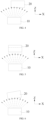
- FIG. 3 is a schematic diagram of the radiation source 10 and ionization chamber 20 in normal positions, and FIG. 3 illustrates that no pose change has occurred on the radiation source 10 and the ionization chamber 20.
- FIG. 4 to FIG. 6 illustrate different pose changes that have occurred on the radiation source 10 and ionization chamber 20, respectively.
- the detection method first obtains the current poses of the radiation source 10 and the ionization chamber 20 separately, then determines whether the radiation source 10 has undergone a pose change with respect to the ionization chamber 20 based on the current poses, so that when the radiation source 10 has undergone a pose change with respect to the ionization chamber 20, corresponding measures can be taken to improve the accuracy of measurement results of the surface density device 100.
- the obtaining (S10) a first current pose of the radiation source 10 and a second current pose of the ionization chamber 20 includes: S110. obtaining current positions of the radiation source 10 and the ionization chamber 20 in at least one direction to determine the first current pose and the second current pose.
- Step S40 includes: S42. determining that the radiation source 10 has undergone a pose change with respect to the ionization chamber 20 in the second direction when the first pose deviation and the second pose deviation are different in degree of deviation.
- the fourth predetermined position 60 may be a position of the surface density device 100 along the Y-direction toward the radiation source 10.
- the fourth predetermined position 60 is a plane perpendicular to the Y-direction of the ionization chamber 50 and the negative direction of the Y-direction passes through the third predetermined position 50, where the third predetermined position 50 and the fourth predetermined position 60 may be in a same plane.
- the fourth current distance may be measured using a fourth distance sensor 104.
- the fourth distance sensor 104 may be installed on the ionization chamber 20 or at the fourth predetermined position 60. To reduce the number of fourth distance sensors 104, in the embodiments of this application, the fourth distance sensor is installed on the radiation source 10.
- the fourth distance sensor 104 is, for example, a laser sensor.
- the fourth distance sensor 104 can measure and obtain the fourth current distance by emitting light and receiving reflected light.
- the third initial distance is a distance measured between the radiation source 10 and the third predetermined position 50 after calibration of the radiation source 10 in the surface density device 100, and based on the third difference, it can be determined whether a position change has occurred on the radiation source 10 in the Y-direction.
- the third current distance is LAY'
- the third initial distance is LAY
- the fourth initial distance is a distance measured between the ionization chamber 20 and the fourth predetermined position 60 after calibration of the ionization chamber 20 in the surface density device 100, and based on the fourth difference, it can be determined whether a position change has occurred on the ionization chamber 20 in the Y-direction.
- the fourth current distance is LBY'
- the fourth initial distance is LBY
- the fourth difference is YBY
- YBY LBY' - YBY
- a large difference between the third difference and the fourth difference indicates that the radiation source 10 has undergone a position change with respect to the ionization chamber 20 in a moving direction of the object under measurement.
- the sixth initial distance is a distance between the ionization chamber 20 and the object under measurement after calibration of the ionization chamber 20 in the surface density device 100, and based on the sixth difference value, it can be determined whether a position change has occurred on the ionization chamber 20 in the Z-direction.
- the sixth current distance is LBZ'
- the sixth initial distance is LBZ
- the sixth difference is ZBZ
- ZBZ LBZ' - ZBZ.
- a large difference between the fifth difference and the sixth difference indicates that the radiation source 10 has undergone a position change with respect to the ionization chamber 20 in a moving direction of the object under measurement.
- the fifth current position and the sixth current position can be used to detect whether the ionization chamber 20 and the radiation source 10 have undergone a pose change relative to each other in the moving direction of thickness under measurement.
- the measurement error due to the thickness difference of the object under measurement is negligible because the thickness difference of the object under measurement is small.
- step S11 includes:
- Step S12 includes:
- Step S40 includes: S44. determining that the radiation source 10 has undergone a torsional pose change with respect to the ionization chamber 20 when the first pose deviation and the second pose deviation are different in degree of deviation.
- the first current distance may be measured using the first distance sensor 101.
- the first distance sensor 101 may be installed at the first radiation site of the radiation source 10 or at the first predetermined position 30.
- the first distance sensor 101 is, for example, a laser sensor.
- the first distance sensor 101 can measure and obtain the first current distance by emitting light and receiving reflected light.
- the seventh current distance may be measured using a seventh distance sensor 107.
- the seventh distance sensor 107 may be installed at the second radiation site of the radiation source 10 or at the first predetermined position 30.
- the seventh distance sensor 107 is, for example, a laser sensor.
- the seventh distance sensor 107 may measure and obtain the seventh current distance by emitting light and receiving reflected light.
- the first radiation site and the second radiation site are two different positions on the radiation source 10, and the first radiation site and the second radiation site may be entities, such as planes or structures, with specific features.
- a first torsion angle of the radiation source 10 may be calculated based on the first current distance, the seventh current distance, and the first predetermined distance, the first predetermined distance being a distance between the center of the first radiation site and the center of the second radiation site.
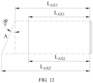
- the first predetermined distance is the distance measured between the radiation source 10 and the first predetermined position 30 after calibration of the radiation source 10 in the surface density device 100. Refer to FIG. 12 .
- the first current distance is LAX1'
- the seventh current distance is LAX2'
- the first initial distance is LAX1
- the seventh initial distance is LAX2
- the first predetermined distance is A
- a second current distance between a first ionization site of the ionization chamber 20 and the second predetermined position 40 in a moving direction of the first ionization site may be obtained as one of the second current positions; and an eighth current distance between a second ionization site of the ionization chamber 20 and the second predetermined position 40 in a moving direction of the second ionization site may be obtained as another second current position.
- the second current distance may be measured using the second distance sensor 102.
- the second distance sensor 102 may be installed at the first ionization site of the ionization chamber 20 or at the second predetermined position 40.
- the second distance sensor 102 is, for example, a laser sensor.
- the second distance sensor 102 can measure and obtain the second current distance by emitting light and receiving reflected light.
- the eighth current distance may be measured using an eighth distance sensor 108.
- the eighth distance sensor 108 may be installed at the second ionization site of the ionization chamber 20 or at the second predetermined position 40.
- the eighth distance sensor 108 is, for example, a laser sensor, and the eighth distance sensor 108 may measure and obtain the eighth current distance by emitting light and receiving reflected light.
- the first ionization site and the second ionization site are two different positions on the ionization chamber 20, and the first ionization site and the second ionization site may be entities, such as planes or structures, with specific features.
- first predetermined distance A may be equal to the second predetermined distance B.
- step S44 it can be determined that the radiation source 10 has undergone a pose change with respect to the ionization chamber 20 when a sum of the first torsion angle and the second torsion angle is greater than a torsion angle threshold.
- a large sum of the first torsion angle and the second torsion angle indicates that the radiation source 10 has undergone a position change with respect to the ionization chamber 20 in a moving direction of the radiation source 10.
- initial poses need to be determined in advance so that a relationship between a current pose and an initial pose can be detected in real time for the radiation source 10 and the ionization chamber 20. Therefore, after the calibration of the surface density device 100, a respective initial pose at multiple positions is obtained, so that multiple initial poses can be obtained and whether a pose change has occurred on the radiation source 10 and the ionization chamber 20 can be detected and determined when the radiation source 10 and the ionization chamber 20 are at any position during operation.
- the obtaining (S10) a first current pose of the radiation source 10 and a second current pose of the ionization chamber 20 includes:
- the first to the eighth distance sensors can be used to measure corresponding distances to obtain current poses of the radiation source 10 and the ionization chamber 20. In this way, current poses of the radiation source 10 and the ionization chamber 20 can be easily obtained based on the distance sensors.
- the detection method further includes: S50. correcting a measurement result of the surface density device 100 based on an amount of pose change when the radiation source 10 has undergone a pose change with respect to the ionization chamber 20.
- the measurement result of the surface density device 100 is corrected based on the amount of pose change, making the measurement result of the surface density device 100 more accurate. For example, when it is determined that the radiation source 10 having undergone a pose change with respect to the ionization chamber 20 causes the measurement result to be too large, the measurement result can be corrected and reduced to make the measurement result more accurate.
- the surface density device 100 in the embodiments of this application includes a radiation source 10, an ionization chamber 20 spaced from the radiation source 10, a memory, a processor, and a computer program stored on the memory and capable of running on the processor, where when the program is executed by the processor, the steps of the method in any one of the foregoing embodiments are implemented.
- the processor may perform the following steps of the detection method:
- the computer-readable medium includes the following: an electrically connected portion with one or more wiring (electronic apparatus), a portable computer disk cartridge (magnetic apparatus), a random access memory (RAM), a read-only memory (ROM), an erasable editable read-only memory (EPROM or flash memory), a fiber optic apparatus, and a portable compact disc read-only memory (CDROM).
- the computer-readable medium may even be a paper on which the program may be printed or other suitable medium, because the program may be obtained electronically, for example, through optical scanning of the paper or other medium, followed by editing, decoding, or, if necessary, processing in other suitable ways, and then the program is stored in a computer memory.
Landscapes
- Physics & Mathematics (AREA)
- General Physics & Mathematics (AREA)
- Health & Medical Sciences (AREA)
- Biochemistry (AREA)
- Chemical & Material Sciences (AREA)
- Analytical Chemistry (AREA)
- Life Sciences & Earth Sciences (AREA)
- General Health & Medical Sciences (AREA)
- Immunology (AREA)
- Pathology (AREA)
- Electromagnetism (AREA)
- Toxicology (AREA)
- Length-Measuring Devices Using Wave Or Particle Radiation (AREA)
Abstract
Description
- This application claims priority and interest to Patent Application No.
202211394373.2 filed with the China National Intellectual Property Administration on November 08, 2022 - This application relates to the field of detection technologies, and in particular, to a detection method, a surface density device, a detection means, and a storage medium.
- A surface density device is a device for measuring the thickness and/or density of sheet objects. The surface density device generally includes a radiation source and an ionization chamber. When the surface density device is in operation, an object under measurement is placed between the radiation source and the ionization chamber, and the radiation source emits rays to the object under measurement. The rays pass through the object under measurement and enter the ionization chamber, and the ionization chamber determines a thickness and/or density of the object under measurement according to the degree of attenuation of the rays. However, the relative position between the radiation source and the ionization chamber may change when the surface density device is used for a long time, resulting in inaccurate measurement results.
- Embodiments of this application provide a detection method, a surface density device, a detection means, and a storage medium, so as to at least partially solve the technical problem of inaccurate measurement results caused by a change of the relative position between a radiation source and an ionization chamber that may occur when the surface density device is used for a long time.
- In a detection method of the surface density device according to an embodiment of this application, where the surface density device includes a radiation source and an ionization chamber spaced from the radiation source, and the detection method includes:
- obtaining, during operation of the surface density device, a first current pose of the radiation source and a second current pose of the ionization chamber;
- determining a first pose deviation of the radiation source based on the first current pose;
- determining a second pose deviation of the ionization chamber based on the second current pose; and
- determining whether the radiation source has undergone a pose change with respect to the ionization chamber based on the first pose deviation and the second pose deviation.
- The detection method according to the embodiment of this application first obtains the current poses of the radiation source and the ionization chamber separately, then determines whether the radiation source has undergone a pose change with respect to the ionization chamber based on the current poses, so that when the radiation source has undergone a pose change with respect to the ionization chamber, corresponding measures can be taken to improve the accuracy of measurement results of the surface density device.
- In addition, poses of the radiation source and the ionization chamber are detected during operation of the surface density device, which makes a measurement process more convenient without stopping the surface density device and facilitates correction of a measurement result of the surface density device in real time, making the measurement efficiency of the surface density device higher.
- In some embodiments, the obtaining a first current pose of the radiation source and a second current pose of the ionization chamber includes:
obtaining current positions of the radiation source and the ionization chamber in at least one direction to determine the first current pose and the second current pose. - In this way, the first current pose and the second current pose are more easily determined.
- In some embodiments, the obtaining current positions of the radiation source and the ionization chamber in at least one direction to determine the first current pose and the second current pose includes:
- obtaining a first current position of the radiation source in a first direction, the first direction being the same as a moving direction of the radiation source;
- obtaining a second current position of the ionization chamber in the first direction, where the first current pose includes the first current position and the second current pose includes the second current position; and
- the determining whether the radiation source has undergone a pose change with respect to the ionization chamber based on the first pose deviation and the second pose deviation includes:
determining that the radiation source has undergone a pose change with respect to the ionization chamber in the first direction when the first pose deviation and the second pose deviation are different in degree of deviation. - In this way, it is possible to detect whether the ionization chamber and the radiation source have undergone a pose change relative to each other in the first direction.
- In some embodiments, the obtaining a first current position of the radiation source in a first direction includes:
- obtaining first current positions of two different sites of the radiation source in the first direction;
- determining a first torsional amount of the radiation source based on the two first current positions, where the first current pose includes the first torsional amount;
- the obtaining a second current position of the ionization chamber in the first direction includes:
- obtaining second current positions of two different sites of the ionization chamber in the first direction; and
- determining a second torsional amount of the ionization chamber based on the two second current positions, where the second current pose includes the second torsional amount; and
- the determining whether the radiation source has undergone a pose change with respect to the ionization chamber based on the first pose deviation and the second pose deviation includes:
determining that the radiation source has undergone a torsional pose change with respect to the ionization chamber when the first pose deviation and the second pose deviation are different in degree of deviation.
- In this way, it is possible to determine whether a pose change in a torsional state between the radiation source and the ionization chamber has occurred.
- In some embodiments, the obtaining current positions of the radiation source and the ionization chamber in at least one direction to determine the first current pose and the second current pose includes:
- obtaining a third current position of the radiation source in a second direction, where the second direction is perpendicular to a moving direction of the radiation source, and the second direction is perpendicular to an arrangement direction of the radiation source and the ionization chamber; and
- obtaining a fourth current position of the radiation source in the second direction, where the first current pose includes the third current position and the second current pose includes the fourth current position; and
- the determining whether the radiation source has undergone a pose change with respect to the ionization chamber based on the first pose deviation and the second pose deviation includes:
determining that the radiation source has undergone a pose change with respect to the ionization chamber in the second direction when the first pose deviation and the second pose deviation are different in degree of deviation. - In this way, it is possible to detect whether the ionization chamber and the radiation source have undergone a pose change relative to each other in the second direction.
- In some embodiments, the obtaining current positions of the radiation source and the ionization chamber in at least one direction to determine the first current pose and the second current pose includes:
- obtaining a fourth current position of the radiation source in a third direction, the third direction being the same as an arrangement direction of the radiation source and the ionization chamber; and
- obtaining a fifth current position of the radiation source in the third direction, where the first current pose includes the fourth current position and the second current pose includes the fifth current position; and
- the determining whether the radiation source has undergone a pose change with respect to the ionization chamber based on the first pose deviation and the second pose deviation includes:
determining that the radiation source has undergone a pose change with respect to the ionization chamber in the third direction when the first pose deviation and the second pose deviation are different in degree of deviation. - In this way, it is possible to detect whether the ionization chamber and the radiation source have undergone a pose change relative to each other in the third direction.
- In some embodiments, the detection method further includes:
correcting a measurement result of the surface density device based on an amount of pose change when the radiation source has undergone a pose change with respect to the ionization chamber. - In this way, the measurement result of the surface density device is corrected based on the amount of pose change, making the measurement result of the surface density device more accurate.
- A surface density device according to an embodiment of this application includes:
- a radiation source;
- an ionization chamber spaced from the radiation source;
- a memory, a processor, and a computer program stored in the memory and capable of running on the processor, where when the program is executed by the processor, the steps of the method in any one of the foregoing embodiments are implemented.
- In this way, the current poses of the radiation source and the ionization chamber are first obtained separately, and then it is determined whether the radiation source has undergone a pose change with respect to the ionization chamber based on the current poses, so that when the radiation source has undergone a pose change with respect to the ionization chamber, corresponding measures can be taken to improve the accuracy of measurement results of the surface density device.
- In some embodiments, both the radiation source and the ionization chamber are provided with distance sensors, the distance sensors being configured to detect distances from the radiation source and the ionization chamber to a predetermined position.
- In this way, current poses of the radiation source and the ionization chamber can be easily obtained based on the distance sensors.
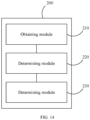
- A detection means includes:
- an obtaining module configured to obtain, during operation of a surface density device, a first current pose of the radiation source of the surface density device and a second current pose of the ionization chamber of the surface density device;
- an determining module configured to determine a first pose deviation of the radiation source based on the first current pose and a second pose deviation of the ionization chamber based on the second current pose; and
- a determining module configured to determine whether the radiation source has undergone a pose change with respect to the ionization chamber based on the first pose deviation and the second pose deviation.
- In this way, the current poses of the radiation source and the ionization chamber are first obtained separately, and then it is determined whether the radiation source has undergone a pose change with respect to the ionization chamber based on the current poses, so that when the radiation source has undergone a pose change with respect to the ionization chamber, corresponding measures can be taken to improve the accuracy of measurement results of the surface density device.
- A non-volatile computer-readable storage medium of computer-executable instructions, where when the computer-executable instructions are executed by one or more processors, the processors are enabled to perform the detection method in any one of the foregoing embodiments.
- For additional aspects and advantages of this application, some will be given in the following description, and some will become apparent in the following description or will be understood in the practice of this application.
- The above and/or additional aspects and advantages of this application will become obvious and easy to understand from the description of the embodiments with reference to the following drawings.
-
FIG. 1 is a schematic flowchart of a detection method according to an embodiment of this application; -
FIG. 2 is a three-dimensional diagram of a surface density device according to an embodiment of this application; -
FIG. 3 is a schematic diagram of a radiation source and an ionization chamber that are in normal pose according to an embodiment of this application; -
FIG. 4 is a schematic diagram of a pose change of a radiation source with respect to an ionization chamber according to an embodiment of this application; -
FIG. 5 is a schematic diagram of a pose change of a radiation source with respect to an ionization chamber according to an embodiment of this application; -
FIG. 6 is a schematic diagram of a pose change of a radiation source with respect to an ionization chamber according to an embodiment of this application; -
FIG. 7 is a schematic flowchart of a detection method according to an embodiment of this application; -
FIG. 8 is a schematic flowchart of a detection method according to an embodiment of this application; -
FIG. 9 is a schematic flowchart of a detection method according to an embodiment of this application; -
FIG. 10 is a schematic flowchart of a detection method according to an embodiment of this application; -
FIG. 11 is a schematic flowchart of a detection method according to an embodiment of this application; -
FIG. 12 is a schematic diagram of a calculation principle in a detection method according to an embodiment of this application; -
FIG. 13 is a schematic flowchart of a detection method according to an embodiment of this application; and -
FIG. 14 is a schematic diagram of a module of a detection means according to an embodiment of this application. - Reference signs of the accompanying drawings are described as follows:
-
surface density device 100,radiation source 10,ionization chamber 20, firstpredetermined position 30, secondpredetermined position 40, thirdpredetermined position 50, fourthpredetermined position 60; -
first distance sensor 101,second distance sensor 102,third distance sensor 103,fourth distance sensor 104,fifth distance sensor 105,sixth distance sensor 106,seventh distance sensor 107,eighth distance sensor 108; and - detection means 200, obtaining
module 210, determiningmodule 220, and determiningmodule 230. - The following describes in detail the embodiments of technical solutions of this application with reference to the accompanying drawings. The following embodiments are merely intended for a clearer description of the technical solutions of this application and therefore are used as just examples which do not constitute any limitations on the protection scope of this application.
- Unless otherwise defined, all technical and scientific terms used herein shall have the same meanings as commonly understood by those skilled in the art to which this application relates. The terms used herein are intended to merely describe the specific embodiments rather than to limit this application. The terms "include", "comprise", and "have" and any other variations thereof in the specification, claims and brief description of drawings of this application are intended to cover non-exclusive inclusions.
- In the description of the embodiments of this application, the terms "first", "second" and the like are merely intended to distinguish between different objects, and shall not be understood as any indication or implication of relative importance or any implicit indication of the number, sequence or primary-secondary relationship of the technical features indicated. In the description of this application, "a plurality of" means at least two unless otherwise specifically stated.
- In this specification, reference to "embodiment" means that specific features, structures or characteristics described with reference to the embodiment may be incorporated in at least one embodiment of this application. The word "embodiment" appearing in various places in the specification does not necessarily refer to the same embodiment or an independent or alternative embodiment that is exclusive of other embodiments. It is explicitly or implicitly understood by persons skilled in the art that the embodiments described herein may be combined with other embodiments.
- In the description of the embodiments of this application, the term "and/or" is only an associative relationship for describing associated objects, indicating that three relationships may be present. For example, A and/or B may indicate the following three cases: presence of only A, presence of both A and B, and presence of only B. In addition, the character "/" in this specification generally indicates an "or" relationship between contextually associated objects.
- In the description of the embodiments of this application, the term "a plurality of" means more than two (inclusive). Similarly, "a plurality of groups" means more than two (inclusive) groups, and "a plurality of pieces" means more than two (inclusive) pieces.
- In the description of the embodiments of this application, unless otherwise specified and defined explicitly, the terms "mount", "connect", "join", and "fasten" should be understood in their general senses. For example, they may refer to a fixed connection, a detachable connection, or an integral connection, may refer to a mechanical connection or electrical connection, and may refer to a direct connection, an indirect connection via an intermediate medium, or an interaction between two elements. Persons of ordinary skill in the art can understand specific meanings of these terms in this application as appropriate to specific situations.
- A surface density device is a device for measuring the thickness and/or density of sheet objects. The surface density device generally includes a radiation source and an ionization chamber. When the surface density device is in operation, an object under measurement (for example, an electrode plate) is placed between the radiation source and the ionization chamber, and the radiation source emits rays to the object under measurement. The rays pass through the object under measurement and enter the ionization chamber, and the ionization chamber determines a thickness and/or density of the object under measurement according to the degree of attenuation of the rays.
- In surface density device, the radiation source and ionization chamber are generally installed on a guide rail. After the surface density device is assembled and commissioned, the radiation source and ionization chamber reciprocate on the guide rail to scan and detect an object under measurement. After the density device has been used for a period of time, if the guide rails and other components of the surface density device undergo large deformation, loose fasteners, wear and tear of transmission parts, and the like, the relative pose between the radiation source and the detector changes, and then effective rays emitted by the radiation source and passed through the object under measurement cannot be completely received by the ionization chamber, resulting in inaccurate measurement results of the surface density device.
- The inventors found through statistics that if a lateral displacement between the radiation source and the ionization chamber is 4 mm, the measurement accuracy of the surface density device is reduced by about 11%; that if a longitudinal displacement between the radiation source and the ionization chamber is 4 mm, the measurement accuracy of the surface density device is reduced by about 5.5%; and that if opposite faces of the radiation source and the ionization chamber are twisted by 2°, the measurement accuracy of the surface density device is reduced by about 5%.
- For the above technical problems, after research, the inventors have known that the surface density device can be serviced regularly when the surface density device does not need to measure an object under measurement, so as to ensure the measurement accuracy of the surface density device. However, the surface density device may fail between two maintenance processes, resulting in wrong measurement results for a large number of measured objects and leading to serious economic losses.
- In view of this, through careful research by the inventors, by detecting the poses of the radiation source and the ionization chamber in real time during operation of the surface density device to determine whether the relative pose between the radiation source and the ionization chamber has changed and taking corresponding measures in a timely manner to improve the measurement accuracy of the surface density device, the inventors have solved the technical problem of inaccurate measurement results caused by a change of the relative position between the radiation source and the ionization chamber that may occur.
- Refer to
FIG. 1 andFIG. 2 .FIG. 1 is a schematic flowchart of a detection method according to an embodiment of this application.FIG. 2 is a three-dimensional diagram of asurface density device 100 according to an embodiment of this application. - The detection method according to the embodiment of this application is applied to a
surface density device 100, where thesurface density device 100 includes aradiation source 10 and anionization chamber 20 spaced from theradiation source 10, and the detection method includes: -
S 10. obtaining, during operation of thesurface density device 100, a first current pose of theradiation source 10 and a second current pose of theionization chamber 20; - S20. determining a first pose deviation of the
radiation source 10 based on the first current pose; - S30. determining a second pose deviation of the
ionization chamber 20 based on the second current pose; - S40. determining whether the
radiation source 10 has undergone a pose change with respect to theionization chamber 20 based on the first pose deviation and the second pose deviation. - Specifically, the
surface density device 100 is an apparatus for measuring the thickness and/or density of sheet objects. Theradiation source 10 is a component for emitting detection rays, the detection rays being, for example, X-rays. The rays emitted by theradiation source 10 is directed toward theionization chamber 20, or in other words, theradiation source 10 emits rays toward theionization chamber 20. Theionization chamber 20 is a component for receiving detection rays, and theionization chamber 20 is also called a detector. In the orientation shown inFIG. 2 , theionization chamber 20 is provided above theradiation source 10. A gap is present between theionization chamber 20 and theradiation source 10 and an object under measurement is located in the gap. - During operation of the
surface density device 100, theradiation source 10 and theionization chamber 20 can move reciprocally in direction X (a first direction) synchronously, and the object under measurement can move in direction Y (a second direction), and theradiation source 10 emits detection rays in direction Z (a third direction), so that the detection rays pass through the object under measurement and enter theionization chamber 20 and are captured by theionization chamber 20. Thesurface density device 100 can calculate the weight per unit area (that is, the surface density) of the obj ect under measurement based on the intensity of the detection rays captured by theionization chamber 20. - In step S10, the operation of the
surface density device 100 refers to a process in which thesurface density device 100 is detecting parameters of the object under measurement such as the surface density. The pose of theradiation source 10 is the position and posture of theradiation source 10, for example, a distance of theradiation source 10 with respect to a reference position, an angle of rotation, and other parameters. The reference position here may be a single position or a plurality of different positions. Similarly, the pose of theionization chamber 20 is the position and posture of theionization chamber 20. The current pose is a pose detected in real time. For example, a pose detected by theradiation source 10 at the current moment is the current pose. - The first current pose and the second current pose may be measured by sensors such as distance sensors. For example, a distance sensor may be installed on the
radiation source 10, and the first current pose is obtained according to a distance that is between the distance sensor and a fixed position on the surface density device and measured by the distance sensor. For example, the first current pose and the second current pose may be measured by a sensor such as a gyroscope. This application does not impose limitation on the specific way of detecting the first current pose and the second current pose. - In steps S20 and S30, the first pose deviation may be a deviation amount of the first current pose with respect to a first initial pose, and the second pose deviation may be a deviation amount of the second current pose with respect to a second initial pose.
- The first initial pose and the second initial pose are respective poses of the
radiation source 10 and theionization chamber 20 at a position of a motion stroke after assembly and calibration of thesurface density device 100. The first initial pose may be measured by a relevant device and maintained in thesurface density device 100. For example, the first initial pose may be measured by a detection component such as a sensor. - It can be understood that if the value of the first current pose is equal to the value of the first initial pose, then the first pose deviation is 0. In other words, the current pose of the
radiation source 10 does not change with respect to the initial pose. - In step S40, if at least one of the first pose deviation and the second pose deviation is greater than a deviation threshold, and the first pose deviation and the second pose deviation cannot cancel each other out, then it may be indicated that the
radiation source 10 has undergone a pose change with respect to theionization chamber 20. For example, if theradiation source 10 and theionization chamber 20 change a same distance in a same direction, then it is considered that the first pose deviation and the second pose deviation can cancel each other out, and no pose change has occurred on theradiation source 10 and theionization chamber 20. - As shown in
FIG. 3, FIG. 3 is a schematic diagram of theradiation source 10 andionization chamber 20 in normal positions, andFIG. 3 illustrates that no pose change has occurred on theradiation source 10 and theionization chamber 20.FIG. 4 to FIG. 6 illustrate different pose changes that have occurred on theradiation source 10 andionization chamber 20, respectively. - In this way, the detection method according to the embodiment of this application first obtains the current poses of the
radiation source 10 and theionization chamber 20 separately, then determines whether theradiation source 10 has undergone a pose change with respect to theionization chamber 20 based on the current poses, so that when theradiation source 10 has undergone a pose change with respect to theionization chamber 20, corresponding measures can be taken to improve the accuracy of measurement results of thesurface density device 100. - In addition, poses of the
radiation source 10 and theionization chamber 20 are detected during operation of thesurface density device 100, which makes a measurement process more convenient without stopping thesurface density device 100 and facilitates correction of a measurement result of thesurface density device 100 in real time, making the measurement efficiency of thesurface density device 100 higher. - Refer to
FIG. 7 . In some embodiments, the obtaining (S10) a first current pose of theradiation source 10 and a second current pose of theionization chamber 20 includes:
S110. obtaining current positions of theradiation source 10 and theionization chamber 20 in at least one direction to determine the first current pose and the second current pose. - Specifically, a current position of the
radiation source 10 in a direction may be expressed in terms of a distance between theradiation source 10 and a predetermined position. For example, a three-dimensional coordinate system may be set up on thesurface density device 100, and the current position of theradiation source 10 may be determined based on coordinates of theradiation source 10. Similarly, a current position of theionization chamber 20 in a direction may be expressed in terms of a distance between theionization chamber 20 and a predetermined position. - In this way, the first current pose and the second current pose are more easily determined.
- Refer to
FIG. 8 . In some embodiments, step S110 includes: - S 11. obtaining a first current position of the
radiation source 10 in a first direction (such as X-direction inFIG. 2 ), the first direction being the same as a moving direction of theradiation source 10; and - S12. obtaining a second current position of the
ionization chamber 20 in the first direction, where the first current pose includes the first current position and the second current pose includes the second current position. - Step S40 includes:
S41. determining that theradiation source 10 has undergone a pose change with respect to theionization chamber 20 in the first direction when the first pose deviation and the second pose deviation are different in degree of deviation. - Specifically, in step S11, the first current position may be represented by a distance. In other words, a first current distance between the
radiation source 10 and a firstpredetermined position 30 in the first direction may be obtained to determine the first current position. Theradiation source 10 may reciprocate back and forth in the X-direction. The firstpredetermined position 30 may be a position of thesurface density device 100 along the X-direction toward theradiation source 10. For example, in the embodiments of this application, the firstpredetermined position 30 is a plane located in positive X-direction of theradiation source 10. The first current distance may be measured using afirst distance sensor 101. Thefirst distance sensor 101 may be installed on theradiation source 10 or at the firstpredetermined position 30. Thefirst distance sensor 101 is, for example, a laser sensor. Thefirst distance sensor 101 can measure and obtain the first current distance by emitting light and receiving reflected light. - In step S12, the second current position may be represented by a distance. In other words, a second current distance between the
ionization chamber 20 and a secondpredetermined position 40 in the first direction may be obtained to determine the second current position. Theionization chamber 20 reciprocates back and forth in the X-direction. The secondpredetermined position 40 may be a position of thesurface density device 100 along the X-direction toward theionization chamber 20. For example, in the embodiments of this application, the secondpredetermined position 40 is a plane located in positive X-direction of theionization chamber 20. The second current distance may be measured using asecond distance sensor 102. Thesecond distance sensor 102 may be installed on theionization chamber 20 or at the secondpredetermined position 40. Thesecond distance sensor 102 is, for example, a laser sensor. Thesecond distance sensor 102 can measure and obtain the second current distance by emitting light and receiving reflected light. - In step S41, a difference between the first current distance and a first initial distance may be calculated and used as a first difference; and a difference between the second current distance and a second initial distance may be calculated and used as a second difference; and when a difference between the first difference and the second difference is greater than a first predetermined difference, it is determined that the
radiation source 10 has undergone a pose change with respect to theionization chamber 20. - Specifically, the first initial distance is a distance measured between the
radiation source 10 and the firstpredetermined position 30 after calibration of theradiation source 10 in thesurface density device 100, and based on the first difference, it can be determined whether a position change has occurred on theradiation source 10 in the X-direction. In one example, the first current distance is LAX1', the first initial distance is LAX1, and the first difference is XA1, then XA1 = LAX1' - LAX1. - The second initial distance is a distance measured between the
ionization chamber 20 and the secondpredetermined position 40 after calibration of theionization chamber 20 in thesurface density device 100, and based on the second difference, it can be determined whether a position change has occurred on theionization chamber 20 in the X-direction. In one example, the second current distance is LBX1', the second initial distance is LBX1, and the second difference is XB 1, then XB 1 = LBX1' - LBX1. - A large difference between the first difference and the second difference indicates that the
radiation source 10 has undergone a position change with respect to theionization chamber 20 in a moving direction of theradiation source 10. In one example, the difference between the first difference and the second difference is ΔX, and ΔX = XA1 - XB 1. If ΔX is greater than the first predetermined difference, it is determined that theradiation source 10 has undergone a pose change with respect to theionization chamber 20. - In summary, the first current position and the second current position can be used to detect whether the
ionization chamber 20 and theradiation source 10 have undergone a pose change relative to each other in the first direction. - Refer to
FIG. 9 . In some embodiments, step S110 includes: - S13. obtaining a third current position of the
radiation source 10 in a second direction (such as Y-direction inFIG. 2 ), where the second direction is perpendicular to a moving direction of theradiation source 10, and the second direction is perpendicular to an arrangement direction of theradiation source 10 and theionization chamber 20; and - S14. obtaining a fourth current position of the
radiation source 10 in the second direction, where the first current pose includes the third current position and the second current pose includes the fourth current position. - Step S40 includes:
S42. determining that theradiation source 10 has undergone a pose change with respect to theionization chamber 20 in the second direction when the first pose deviation and the second pose deviation are different in degree of deviation. - Specifically, in step S13, the third current position may be represented by a distance. In other words, a third current distance between the
radiation source 10 and a thirdpredetermined position 50 in the second direction may be obtained to determine the third current position. An object under measurement may move along the Y-direction. The thirdpredetermined position 50 may be a position of thesurface density device 100 along the Y-direction toward theradiation source 10. For example, in the embodiments of this application, the thirdpredetermined position 50 may be a plane perpendicular to the Y-direction of theradiation source 10 and the negative Y-direction passes through the thirdpredetermined position 50. The third current distance may be measured using athird distance sensor 103. Thethird distance sensor 103 may be installed on theradiation source 10 or at the thirdpredetermined position 50. To reduce the number ofthird distance sensors 103, in the embodiments of this application, thethird distance sensor 103 is installed on theradiation source 10. Thethird distance sensor 103 is, for example, a laser sensor. Thethird distance sensor 103 can measure and obtain the third current distance by emitting light and receiving reflected light. - In step S14, the fourth current position may be represented by a distance. In other words, a fourth current distance between the
ionization chamber 20 and a fourthpredetermined position 60 in the second direction may be obtained to determine the fourth current position. - The fourth
predetermined position 60 may be a position of thesurface density device 100 along the Y-direction toward theradiation source 10. For example, in the embodiments of this application, the fourthpredetermined position 60 is a plane perpendicular to the Y-direction of theionization chamber 50 and the negative direction of the Y-direction passes through the thirdpredetermined position 50, where the thirdpredetermined position 50 and the fourthpredetermined position 60 may be in a same plane. The fourth current distance may be measured using afourth distance sensor 104. Thefourth distance sensor 104 may be installed on theionization chamber 20 or at the fourthpredetermined position 60. To reduce the number offourth distance sensors 104, in the embodiments of this application, the fourth distance sensor is installed on theradiation source 10. Thefourth distance sensor 104 is, for example, a laser sensor. Thefourth distance sensor 104 can measure and obtain the fourth current distance by emitting light and receiving reflected light. - In step S42, a difference between the third current distance and a third initial distance may be calculated and used as a third difference; and a difference between the fourth current distance and a fourth initial distance may be calculated and used as a fourth difference; and when a difference between the third difference and the fourth difference is greater than a second predetermined difference, it is determined that the
radiation source 10 has undergone a pose change with respect to theionization chamber 20. - The third initial distance is a distance measured between the
radiation source 10 and the thirdpredetermined position 50 after calibration of theradiation source 10 in thesurface density device 100, and based on the third difference, it can be determined whether a position change has occurred on theradiation source 10 in the Y-direction. In one example, the third current distance is LAY', the third initial distance is LAY, and the third difference is YAY; then, YAY = LAY' - YAY - The fourth initial distance is a distance measured between the
ionization chamber 20 and the fourthpredetermined position 60 after calibration of theionization chamber 20 in thesurface density device 100, and based on the fourth difference, it can be determined whether a position change has occurred on theionization chamber 20 in the Y-direction. In one example, the fourth current distance is LBY', the fourth initial distance is LBY, and the fourth difference is YBY, then YBY = LBY' - YBY - A large difference between the third difference and the fourth difference indicates that the
radiation source 10 has undergone a position change with respect to theionization chamber 20 in a moving direction of the object under measurement. In one example, the difference between the third difference and the second difference is ΔY, and ΔY = YAY - YBY If ΔY is greater than the second predetermined difference, it is determined that theradiation source 10 has undergone a pose change with respect to theionization chamber 20. - In this way, the third current position and fourth current position can be used to detect whether the
ionization chamber 20 and theradiation source 10 have undergone a pose change relative to each other in the moving direction of the object under measurement. - Refer to
FIG. 10 . In some embodiments, step S110 includes: - S15. obtaining a fourth current position of the
radiation source 10 in a third direction (such as Z-direction inFIG. 2 ), the third direction being the same as an arrangement direction of theradiation source 10 and theionization chamber 20; and - S16. obtaining a fifth current position of the
radiation source 10 in the third direction, where the first current pose includes the fourth current position and the second current pose includes the fifth current position. - Step S40 includes:
S43. determining that theradiation source 10 has undergone a pose change with respect to theionization chamber 20 in the third direction when the first pose deviation and the second pose deviation are different in degree of deviation. - In step S15, the fifth current position may be expressed by a distance. In other words, a fifth current distance between the
radiation source 10 and the object under measurement may be obtained to determine the fifth current position. The object under measurement is located in the Z-direction of theradiation source 10, and the fifth current distance may be measured using thefifth distance sensor 105. Thefifth distance sensor 105 may be installed on theradiation source 10. Thefifth distance sensor 105 is, for example, a laser sensor. Thefifth distance sensor 105 can measure and obtain the fifth current distance by emitting light and receiving reflected light. - In step S16, a sixth current position may be represented by a distance. In other words, a sixth current distance between the
ionization chamber 20 and the object under measurement may be obtained to determine the sixth current position. The sixth current distance may be measured using asixth distance sensor 106. Thesixth distance sensor 106 may be installed on theionization chamber 20. Thesixth distance sensor 106 is, for example, a laser sensor. Thesixth distance sensor 106 may measure and obtain the sixth current distance by emitting light and receiving reflected light. - In step S43, a difference between the fifth current distance and a fifth initial distance may be calculated and used as a fifth difference; and a difference between the sixth current distance and a sixth initial distance may be calculated and used as a sixth difference; and when a sum of the fifth difference and the sixth difference is greater than a predetermined value, it is determined that the
radiation source 10 has undergone a pose change with respect to theionization chamber 20. - The fifth initial distance is a distance measured between the
radiation source 10 and the object under measurement after calibration of theradiation source 10 in thesurface density device 100, and based on the fifth difference, it can be determined whether a position change has occurred on theradiation source 10 in the Z-direction. In one example, the fifth current distance is LAZ', the fifth initial distance is LAZ, and the fifth difference is ZAZ; then, ZAZ = LAZ' - ZAZ. - The sixth initial distance is a distance between the
ionization chamber 20 and the object under measurement after calibration of theionization chamber 20 in thesurface density device 100, and based on the sixth difference value, it can be determined whether a position change has occurred on theionization chamber 20 in the Z-direction. In one example, the sixth current distance is LBZ', the sixth initial distance is LBZ, and the sixth difference is ZBZ, then ZBZ = LBZ' - ZBZ. - A large difference between the fifth difference and the sixth difference indicates that the
radiation source 10 has undergone a position change with respect to theionization chamber 20 in a moving direction of the object under measurement. In one example, the difference between the fifth difference and the second difference is ΔZ, and ΔZ = ZAZ - ZBZ. If ΔZ is greater than the second predetermined difference, it is determined that theradiation source 10 has undergone a pose change with respect to theionization chamber 20. - In this way, the fifth current position and the sixth current position can be used to detect whether the
ionization chamber 20 and theradiation source 10 have undergone a pose change relative to each other in the moving direction of thickness under measurement. - It should be noted that the measurement error due to the thickness difference of the object under measurement is negligible because the thickness difference of the object under measurement is small.
- Refer to
FIG. 11 . In some embodiments, step S11 includes: - S111. obtaining first current positions of two different sites of the
radiation source 10 in the first direction; and - S112. determining a first torsional amount of the
radiation source 10 based on the two first current positions, where the first current pose includes the first torsional amount. - Step S12 includes:
- S121. obtaining second current positions of two different sites of the
ionization chamber 20 in the first direction; and - S122. determining a second torsional amount of the
ionization chamber 20 based on the two second current positions, where the second current pose includes the second torsional amount. - Step S40 includes:
S44. determining that theradiation source 10 has undergone a torsional pose change with respect to theionization chamber 20 when the first pose deviation and the second pose deviation are different in degree of deviation. - Specifically, in steps S111 and S112, a first current distance between a first radiation site of the radiation source 1010 and the first
predetermined position 30 in a moving direction of the first radiation site may be obtained as one of the first current positions; and a seventh current distance between a second radiation site of the radiation source 1010 and the firstpredetermined position 30 in a moving direction of the second radiation site may be obtained as another first current position, the second radiation site being on a same side of the radiation source 1010 as the first radiation site. - As discussed above, the first current distance may be measured using the
first distance sensor 101. Thefirst distance sensor 101 may be installed at the first radiation site of theradiation source 10 or at the firstpredetermined position 30. Thefirst distance sensor 101 is, for example, a laser sensor. Thefirst distance sensor 101 can measure and obtain the first current distance by emitting light and receiving reflected light. - Similarly, as shown in
FIG. 2 , the seventh current distance may be measured using aseventh distance sensor 107. Theseventh distance sensor 107 may be installed at the second radiation site of theradiation source 10 or at the firstpredetermined position 30. Theseventh distance sensor 107 is, for example, a laser sensor. Theseventh distance sensor 107 may measure and obtain the seventh current distance by emitting light and receiving reflected light. - In the embodiments of this application, the first radiation site and the second radiation site are two different positions on the
radiation source 10, and the first radiation site and the second radiation site may be entities, such as planes or structures, with specific features. - A first torsion angle of the
radiation source 10 may be calculated based on the first current distance, the seventh current distance, and the first predetermined distance, the first predetermined distance being a distance between the center of the first radiation site and the center of the second radiation site. - The first predetermined distance is the distance measured between the
radiation source 10 and the firstpredetermined position 30 after calibration of theradiation source 10 in thesurface density device 100. Refer toFIG. 12 . In one example, the first current distance is LAX1', the seventh current distance is LAX2', the first initial distance is LAX1, the seventh initial distance is LAX2, the first predetermined distance is A, and the first torsion angle is θA, then
- In steps S121 and S122, a second current distance between a first ionization site of the
ionization chamber 20 and the secondpredetermined position 40 in a moving direction of the first ionization site may be obtained as one of the second current positions; and an eighth current distance between a second ionization site of theionization chamber 20 and the secondpredetermined position 40 in a moving direction of the second ionization site may be obtained as another second current position. - As discussed above, the second current distance may be measured using the
second distance sensor 102. Thesecond distance sensor 102 may be installed at the first ionization site of theionization chamber 20 or at the secondpredetermined position 40. Thesecond distance sensor 102 is, for example, a laser sensor. Thesecond distance sensor 102 can measure and obtain the second current distance by emitting light and receiving reflected light. - Similarly, the eighth current distance may be measured using an
eighth distance sensor 108. Theeighth distance sensor 108 may be installed at the second ionization site of theionization chamber 20 or at the secondpredetermined position 40. Theeighth distance sensor 108 is, for example, a laser sensor, and theeighth distance sensor 108 may measure and obtain the eighth current distance by emitting light and receiving reflected light. - In the embodiments of this application, the first ionization site and the second ionization site are two different positions on the
ionization chamber 20, and the first ionization site and the second ionization site may be entities, such as planes or structures, with specific features. - A second torsion angle of the
radiation source 10 may be calculated based on the second current distance, the eighth current distance, and the second predetermined distance, the second predetermined distance being a distance between the center of the first ionization site and the center of the second ionization site. - The second predetermined distance is the distance measured between the
ionization chamber 20 and the secondpredetermined position 40 after calibration of theradiation source 10 in thesurface density device 100. In one example, the second current distance is LBX1', the seventh current distance is LBX2', the second initial distance is LBX1, the seventh initial distance is LBX2, the second predetermined distance is B, and the second torsion angle is θB, then θB = arcsin([|(LBX1' - LBX1) - (LBX2' - LBX2)1]/B). - It is noted that the first predetermined distance A may be equal to the second predetermined distance B.
- In step S44, it can be determined that the
radiation source 10 has undergone a pose change with respect to theionization chamber 20 when a sum of the first torsion angle and the second torsion angle is greater than a torsion angle threshold. - A large sum of the first torsion angle and the second torsion angle indicates that the
radiation source 10 has undergone a position change with respect to theionization chamber 20 in a moving direction of theradiation source 10. In one example, the sum of the first torsion angle and the second torsion angle is θ, and θ = θA + θB. If θ is greater than the torsion angle threshold, it is determined that theradiation source 10 has undergone a pose change with respect to theionization chamber 20. - In this way, it is possible to determine whether a pose change in a torsional state between the
radiation source 10 and theionization chamber 20 has occurred by using the first torsion angle and the second torsion angle. - In the embodiments of this application, because the
radiation source 10 and theionization chamber 20 move reciprocally during operation, initial poses need to be determined in advance so that a relationship between a current pose and an initial pose can be detected in real time for theradiation source 10 and theionization chamber 20. Therefore, after the calibration of thesurface density device 100, a respective initial pose at multiple positions is obtained, so that multiple initial poses can be obtained and whether a pose change has occurred on theradiation source 10 and theionization chamber 20 can be detected and determined when theradiation source 10 and theionization chamber 20 are at any position during operation. - In some embodiments, the obtaining (S10) a first current pose of the
radiation source 10 and a second current pose of theionization chamber 20 includes: - obtaining the first current pose by using a measurement result of a distance sensor provided on the
radiation source 10; and - obtaining the second current pose by using a measurement result of a distance sensor provided on the
ionization chamber 20. - As discussed above, the first to the eighth distance sensors can be used to measure corresponding distances to obtain current poses of the
radiation source 10 and theionization chamber 20. In this way, current poses of theradiation source 10 and theionization chamber 20 can be easily obtained based on the distance sensors. - Refer to
FIG. 13 . In some embodiments, the detection method further includes:
S50. correcting a measurement result of thesurface density device 100 based on an amount of pose change when theradiation source 10 has undergone a pose change with respect to theionization chamber 20. - In this way, the measurement result of the
surface density device 100 is corrected based on the amount of pose change, making the measurement result of thesurface density device 100 more accurate. For example, when it is determined that theradiation source 10 having undergone a pose change with respect to theionization chamber 20 causes the measurement result to be too large, the measurement result can be corrected and reduced to make the measurement result more accurate. - In addition, in some embodiments, an alert and warning can be issued when the
radiation source 10 has undergone a pose change with respect to theionization chamber 20 to facilitate works such as evaluation of the device status, maintenance, and repair, effectively preventing thesurface density device 100 from working in a faulty state and avoiding safety hazards caused by large batches of products. - The
surface density device 100 in the embodiments of this application includes aradiation source 10, anionization chamber 20 spaced from theradiation source 10, a memory, a processor, and a computer program stored on the memory and capable of running on the processor, where when the program is executed by the processor, the steps of the method in any one of the foregoing embodiments are implemented. - For example, the processor may perform the following steps of the detection method:
- S10. obtaining, during operation of the
surface density device 100, a first current pose of theradiation source 10 and a second current pose of theionization chamber 20; - S20. determining a first pose deviation of the
radiation source 10 based on the first current pose; - S30. determining a second pose deviation of the
ionization chamber 20 based on the second current pose; and - S40. determining whether the
radiation source 10 has undergone a pose change with respect to theionization chamber 20 based on the first pose deviation and the second pose deviation. - In this way, the current poses of the
radiation source 10 and theionization chamber 20 are first obtained separately, and then it is determined whether theradiation source 10 has undergone a pose change with respect to theionization chamber 20 based on the current poses, so that when theradiation source 10 has undergone a pose change with respect to theionization chamber 20, corresponding measures can be taken to improve the accuracy of measurement results of thesurface density device 100. - In some embodiments, both the
radiation source 10 and theionization chamber 20 are provided with distance sensors, the distance sensors being configured to detect distances from theradiation source 10 and theionization chamber 20 to a predetermined position. In this way, current poses of theradiation source 10 and theionization chamber 20 can be easily obtained based on the distance sensors. - It should be noted that the explanatory description of the detection method in the foregoing embodiments is applicable to the detection means of this application, and for parts of the detection means not described in the embodiments of this application, reference may be made to the corresponding part of the foregoing detection method. Details are not repeated herein.
- Refer to
FIG. 14 . A detection means 200 in an embodiment of this application includes an obtainingmodule 210, a determiningmodule 220, and a determiningmodule 230. The obtainingmodule 210 is configured to obtain, during operation of asurface density device 100, a first current pose of theradiation source 10 of thesurface density device 100 and a second current pose of theionization chamber 20 of thesurface density device 100. The determiningmodule 220 is configured to calculate a first pose deviation between the first current pose and a first initial pose of theradiation source 10 and a second pose deviation between the second current pose and a second initial pose of theionization chamber 20. The determiningmodule 230 is configured to determine whether theradiation source 10 has undergone a pose change with respect to theionization chamber 20 based on the first pose deviation and the second pose deviation. - In this way, the current poses of the
radiation source 10 and theionization chamber 20 are first obtained separately, and then it is determined whether theradiation source 10 has undergone a pose change with respect to theionization chamber 20 based on the current poses, so that when theradiation source 10 has undergone a pose change with respect to theionization chamber 20, corresponding measures can be taken to improve the accuracy of measurement results of thesurface density device 100. - It should be noted that the detection means 200 in this embodiment of this application can implement the detection method in any one of the foregoing embodiments. The steps of the detection method in the foregoing embodiments can be performed by the corresponding modules of the detection means 200. Details are not repeated herein.
- In addition, the explanatory description of the detection method in the foregoing embodiments is applicable to the detection means 200 of this application, and for parts of the detection means 200 not described in the embodiments of this application, reference may be made to the corresponding part of the foregoing detection method. Details are not repeated herein.
- A non-volatile computer-readable storage medium of computer-executable instructions, where when the computer-executable instructions are executed by one or more processors, the processors are enabled to perform the detection method in any one of the foregoing embodiments.
- In the description of this specification, reference to the description of the terms "an embodiment", "some embodiments", "an example of the embodiment", "an example", "a specific example", or "some examples" means that particular features, structures, materials or characteristics described in connection with the embodiments or examples are included in at least one embodiment or example of this application. In this specification, descriptions of examples of the above terms do not necessarily refer to the same embodiment or example. Furthermore, the particular features, structures, materials, or characteristics described may be combined in a suitable manner in any one or more embodiments or examples.
- Any process or method description in the flowchart or otherwise described herein may be understood to represent a module, fragment, or portion of code including one or more executable instructions for implementing steps of a particular logical function or process, and the scope of the preferred embodiments of the present invention includes additional implementations in which the functions may be performed not in the order shown or discussed, including performing the functions involved in a substantially simultaneous manner or in a reverse order, as should be understood by those skilled in the art to which the embodiments of the present invention belong.
- The logic and/or steps represented in the flowchart or otherwise described herein, for example, may be considered to be a definitive list of executable instructions for implementing the logical functions, which may be specifically implemented in any computer-readable medium for use by, or in combination with, an instruction execution system, apparatus, or device (for example, a computer-based system, a system including a processing module, or other systems that can obtain instructions from an instruction execution system, apparatus, or device and execute the instructions). For the purposes of this specification, a "computer-readable medium" may be any apparatus that can contain, store, communicate, transfer, or transmit a program for use in or in conjunction with the instruction execution system, apparatus, or device. More specific examples of the computer-readable medium (a non-exhaustive list) include the following: an electrically connected portion with one or more wiring (electronic apparatus), a portable computer disk cartridge (magnetic apparatus), a random access memory (RAM), a read-only memory (ROM), an erasable editable read-only memory (EPROM or flash memory), a fiber optic apparatus, and a portable compact disc read-only memory (CDROM). Alternatively, the computer-readable medium may even be a paper on which the program may be printed or other suitable medium, because the program may be obtained electronically, for example, through optical scanning of the paper or other medium, followed by editing, decoding, or, if necessary, processing in other suitable ways, and then the program is stored in a computer memory.
- It should be understood that the various parts of the embodiments of this invention may be implemented by hardware, software, firmware, or a combination thereof. In the foregoing embodiments, multiple steps or methods may be implemented by software or firmware stored in memory and executed by a suitable instruction execution system. For example, if implemented by hardware, as in another embodiment, they may be implemented by any one of the following techniques known in the art or by a combination thereof: a discrete logic circuit with a logic gate circuit for implementing the logic function on data signals, an application-specific integrated circuit with a suitable combination of logic gate circuits, a programmable gate array (PGA), a field programmable gate array (FPGA), and the like.
- Persons of ordinary skill in the art can understand that all or part of the steps of the foregoing method embodiment to adjust the focal power can be completed by a program to instruct relevant hardware, where the program may be stored in a computer-readable storage medium, and when the program is executed, one of or a combination of the steps of the method embodiment are included.
- In addition, functional units in the various embodiments of this invention may be integrated into one processing module, or each of the units may exist alone physically, or two or more units may be integrated into one module. The integrated module may be implemented in a form of hardware, or may be implemented in a form of a software functional module. When the integrated module is implemented in the form of a software functional module and sold or used as an independent product, the integrated module may also be stored in a computer-readable storage medium. The storage medium mentioned above may be a read-only memory, a disk, a compact disc, or the like.
- In conclusion, it should be noted that the foregoing embodiments are for description of the technical solutions of this application only rather than for limiting this application. Although this application has been described in detail with reference to the foregoing embodiments, persons of ordinary skill in the art should appreciate that they can still make modifications to the technical solutions described in the embodiments or make equivalent replacements to some or all technical features thereof without departing from the scope of the technical solutions of the embodiments of this application. All such modifications and equivalent replacements shall fall within the scope of claims and specification of this application. In particular, as long as there is no structural conflict, the various technical features mentioned in the embodiments can be combined in any manner. This application is not limited to the specific embodiments disclosed in this specification but includes all technical solutions falling within the scope of the claims.
Claims (11)
- A detection method of a surface density device, characterized in that the surface density device comprises a radiation source and an ionization chamber spaced from the radiation source, and the detection method comprises:obtaining, during operation of the surface density device, a first current pose of the radiation source and a second current pose of the ionization chamber;determining a first pose deviation of the radiation source based on the first current pose;determining a second pose deviation of the ionization chamber based on the second current pose; anddetermining whether the radiation source has undergone a pose change with respect to the ionization chamber based on the first pose deviation and the second pose deviation.
- The detection method according to claim 1, wherein the obtaining a first current pose of the radiation source and a second current pose of the ionization chamber comprises:
obtaining current positions of the radiation source and the ionization chamber in at least one direction to determine the first current pose and the second current pose. - The detection method according to claim 2, whereinthe obtaining current positions of the radiation source and the ionization chamber in at least one direction to determine the first current pose and the second current pose comprises:obtaining a first current position of the radiation source in a first direction, the first direction being the same as a moving direction of the radiation source;obtaining a second current position of the ionization chamber in the first direction, wherein the first current pose comprises the first current position and the second current pose comprises the second current position; andthe determining whether the radiation source has undergone a pose change with respect to the ionization chamber based on the first pose deviation and the second pose deviation comprises:
determining that the radiation source has undergone a pose change with respect to the ionization chamber in the first direction when the first pose deviation and the second pose deviation are different in degree of deviation. - The detection method according to claim 3, whereinthe obtaining a first current position of the radiation source in a first direction comprises:obtaining first current positions of two different sites of the radiation source in the first direction;determining a first torsional amount of the radiation source based on the two first current positions, wherein the first current pose comprises the first torsional amount;the obtaining a second current position of the ionization chamber in the first direction comprises:obtaining second current positions of two different sites of the ionization chamber in the first direction; anddetermining a second torsional amount of the ionization chamber based on the two second current positions, wherein the second current pose comprises the second torsional amount; andthe determining whether the radiation source has undergone a pose change with respect to the ionization chamber based on the first pose deviation and the second pose deviation comprises:
determining that the radiation source has undergone a torsional pose change with respect to the ionization chamber when the first pose deviation and the second pose deviation are different in degree of deviation. - The detection method according to claim 2, whereinthe obtaining current positions of the radiation source and the ionization chamber in at least one direction to determine the first current pose and the second current pose comprises:obtaining a third current position of the radiation source in a second direction, wherein the second direction is perpendicular to a moving direction of the radiation source, and the second direction is perpendicular to an arrangement direction of the radiation source and the ionization chamber; andobtaining a fourth current position of the radiation source in the second direction, wherein the first current pose comprises the third current position and the second current pose comprises the fourth current position; andthe determining whether the radiation source has undergone a pose change with respect to the ionization chamber based on the first pose deviation and the second pose deviation comprises:
determining that the radiation source has undergone a pose change with respect to the ionization chamber in the second direction when the first pose deviation and the second pose deviation are different in degree of deviation. - The detection method according to claim 2, whereinthe obtaining current positions of the radiation source and the ionization chamber in at least one direction to determine the first current pose and the second current pose comprises:obtaining a fourth current position of the radiation source in a third direction, the third direction being the same as an arrangement direction of the radiation source and the ionization chamber; andobtaining a fifth current position of the radiation source in the third direction, wherein the first current pose comprises the fourth current position and the second current pose comprises the fifth current position; andthe determining whether the radiation source has undergone a pose change with respect to the ionization chamber based on the first pose deviation and the second pose deviation comprises:
determining that the radiation source has undergone a pose change with respect to the ionization chamber in the third direction when the first pose deviation and the second pose deviation are different in degree of deviation. - The detection method according to claim 1, wherein the detection method further comprises:
correcting a measurement result of the surface density device based on an amount of pose change when the radiation source has undergone a pose change with respect to the ionization chamber. - A surface density device, comprising:a radiation source;an ionization chamber spaced from the radiation source; anda memory, a processor, and a computer program stored in the memory and capable of running on the processor, wherein when the program is executed by the processor, the steps of the method according to any one of claims 1 to 7 are implemented.
- The density device according to claim 8, wherein the radiation source and the ionization chamber are both provided with distance sensors, the distance sensors being configured to detect distances from the radiation source and the ionization chamber to a predetermined position.
- A detection means, characterized by:an obtaining module configured to obtain, during operation of a surface density device, a first current pose of the radiation source of the surface density device and a second current pose of the ionization chamber of the surface density device;a determining module configured to determine a first pose deviation of the radiation source based on the first current pose and a second pose deviation of the ionization chamber based on the second current pose; anda determining module configured to determine whether the radiation source has undergone a pose change with respect to the ionization chamber based on the first pose deviation and the second pose deviation.
- A non-volatile computer-readable storage medium of computer-executable instructions, wherein when the computer-executable instructions are executed by one or more processors, the processors are enabled to perform the steps of the detection method according to any one of claims 1 to 7.
Applications Claiming Priority (2)
| Application Number | Priority Date | Filing Date | Title |
|---|---|---|---|
| CN202211394373.2A CN115931633B (en) | 2022-11-08 | 2022-11-08 | Detection method, surface density device, detection apparatus, and storage medium |
| PCT/CN2023/091278 WO2024098679A1 (en) | 2022-11-08 | 2023-04-27 | Detection method, surface density device, detection apparatus, and storage medium |
Publications (3)
| Publication Number | Publication Date |
|---|---|
| EP4397955A1 true EP4397955A1 (en) | 2024-07-10 |
| EP4397955A4 EP4397955A4 (en) | 2024-09-11 |
| EP4397955B1 EP4397955B1 (en) | 2025-12-31 |
Family
ID=90927366
Family Applications (1)
| Application Number | Title | Priority Date | Filing Date |
|---|---|---|---|
| EP23789483.7A Active EP4397955B1 (en) | 2022-11-08 | 2023-04-27 | METHOD AND DEVICE FOR MEASURING SURFACE DENSITY |
Country Status (3)
| Country | Link |
|---|---|
| US (1) | US12460926B2 (en) |
| EP (1) | EP4397955B1 (en) |
| DK (1) | DK4397955T3 (en) |
Family Cites Families (13)
| Publication number | Priority date | Publication date | Assignee | Title |
|---|---|---|---|---|
| CN86209739U (en) * | 1986-12-06 | 1987-09-16 | 冶金工业部自动化研究所 | Improved-type double light-beam x-ray thickness-meter |
| JP3644922B2 (en) * | 2001-12-06 | 2005-05-11 | 本田技研工業株式会社 | Electric power steering device |
| CN100588960C (en) | 2005-12-29 | 2010-02-10 | 比亚迪股份有限公司 | A system and method for measuring the surface density of battery pole pieces |
| WO2008110017A1 (en) | 2007-03-15 | 2008-09-18 | University Of Northern British Columbia | Systems and methods for monitoring wood product characteristics |
| CN102944498B (en) | 2012-11-08 | 2014-10-08 | 佛山市枫莱尔自动化技术有限公司 | System and method for detecting battery pole piece coating production line online surface density |
| CN103876759A (en) | 2012-12-20 | 2014-06-25 | 上海联影医疗科技有限公司 | X-ray photogrammetry system and control method thereof |
| US10426416B2 (en) * | 2014-09-29 | 2019-10-01 | Shanghai United Imaging Healthcare Co., Ltd. | System and method for digital radiography |
| CN110243723A (en) | 2019-06-05 | 2019-09-17 | 江西力能新能源科技有限公司 | A method for detecting the ceramic coating density of lithium battery positive and negative plates |
| CN114123879B (en) * | 2021-11-25 | 2023-12-12 | 深圳众为兴技术股份有限公司 | Phase detection method, device, electronic equipment and storage medium |
| CN115015039A (en) | 2022-04-27 | 2022-09-06 | 杭州安脉盛智能技术有限公司 | System and method for detecting surface density |
| CN217605573U (en) | 2022-06-24 | 2022-10-18 | 青海盐湖工业股份有限公司 | Radioactive densimeter installation device and radioactive densimeter assembly |
| CN115096756B (en) | 2022-07-27 | 2022-11-22 | 浙江双元科技股份有限公司 | Self-calibration surface density detector and calibration method thereof |
| CN115931633B (en) | 2022-11-08 | 2025-07-29 | 宁德时代新能源科技股份有限公司 | Detection method, surface density device, detection apparatus, and storage medium |
-
2023
- 2023-04-27 EP EP23789483.7A patent/EP4397955B1/en active Active
- 2023-04-27 DK DK23789483.7T patent/DK4397955T3/en active
- 2023-10-23 US US18/382,862 patent/US12460926B2/en active Active
Also Published As
| Publication number | Publication date |
|---|---|
| US12460926B2 (en) | 2025-11-04 |
| DK4397955T3 (en) | 2026-03-23 |
| US20240151521A1 (en) | 2024-05-09 |
| EP4397955A4 (en) | 2024-09-11 |
| EP4397955B1 (en) | 2025-12-31 |
Similar Documents
| Publication | Publication Date | Title |
|---|---|---|
| CN115931633B (en) | Detection method, surface density device, detection apparatus, and storage medium | |
| JP5154430B2 (en) | Spatial area monitoring apparatus and method | |
| RU2655694C2 (en) | Method and device for status tracking of a moving object and system of a vehicle fast inspection | |
| US11192158B2 (en) | Apparatus for detecting relative positioning information between rolls, and method for measurement roll alignment state by using same | |
| US10562644B2 (en) | System and method for aircraft docking guidance and aircraft type identification | |
| US20100315653A1 (en) | Optical sensor for positioning tasks | |
| US20220289026A1 (en) | Object Detection Sensor Alignment | |
| US20120154200A1 (en) | Control apparatus, radar detection system, and radar detection method | |
| US9046349B2 (en) | Method and device for contactless determination of the thickness of a web of material, including correction of the alignment error | |
| KR102925465B1 (en) | Method and device for determining false positive detection of a lidar sensor | |
| JP2014106191A (en) | Laser radar device, inspection system, and target plate | |
| EP3722747A2 (en) | Volume measurement method, device, system and computer-readable storage medium | |
| US6304680B1 (en) | High resolution, high accuracy process monitoring system | |
| US12460926B2 (en) | Detection method, surface density device, detection means, and storage medium | |
| US12455359B2 (en) | Method for calibrating a laser scanner, and technical apparatus | |
| US5079729A (en) | Alignment measuring system & method | |
| KR20010063525A (en) | Apparatus for detecting the edge of colded roll | |
| JP6170714B2 (en) | Ranging device | |
| US20250216518A1 (en) | Control circuit, system, method, and program | |
| EP4386439A1 (en) | A method for diagnosing a change of alignment of a laser rangefinder unit and laser rangefinder unit and system for carrying out said method | |
| US9091531B2 (en) | Method and device for detecting double parts | |
| EP1805482B1 (en) | Method and system for determining the properties of a surface of revolution | |
| KR100252203B1 (en) | Non-contact laminated shadow mask calculation device | |
| JP6819161B2 (en) | Coordinate calculation method and coordinate calculation device | |
| JPH01202608A (en) | Inspecting device for bending of ic lead |
Legal Events
| Date | Code | Title | Description |
|---|---|---|---|
| STAA | Information on the status of an ep patent application or granted ep patent |
Free format text: STATUS: UNKNOWN |
|
| STAA | Information on the status of an ep patent application or granted ep patent |
Free format text: STATUS: THE INTERNATIONAL PUBLICATION HAS BEEN MADE |
|
| PUAI | Public reference made under article 153(3) epc to a published international application that has entered the european phase |
Free format text: ORIGINAL CODE: 0009012 |
|
| STAA | Information on the status of an ep patent application or granted ep patent |
Free format text: STATUS: REQUEST FOR EXAMINATION WAS MADE |
|
| 17P | Request for examination filed |
Effective date: 20231024 |
|
| AK | Designated contracting states |
Kind code of ref document: A1 Designated state(s): AL AT BE BG CH CY CZ DE DK EE ES FI FR GB GR HR HU IE IS IT LI LT LU LV MC ME MK MT NL NO PL PT RO RS SE SI SK SM TR |
|
| REG | Reference to a national code |
Ref country code: DE Ref legal event code: R079 Free format text: PREVIOUS MAIN CLASS: G01N0009240000 Ipc: G01B0015020000 Ref document number: 602023010532 Country of ref document: DE |
|
| A4 | Supplementary search report drawn up and despatched |
Effective date: 20240813 |
|
| RIC1 | Information provided on ipc code assigned before grant |
Ipc: G01N 23/083 20180101ALI20240807BHEP Ipc: G01N 9/24 20060101ALI20240807BHEP Ipc: G01B 15/02 20060101AFI20240807BHEP |
|
| RAP1 | Party data changed (applicant data changed or rights of an application transferred) |
Owner name: CONTEMPORARY AMPEREX TECHNOLOGY(HONG KONG) LIMITED |
|
| STAA | Information on the status of an ep patent application or granted ep patent |
Free format text: STATUS: EXAMINATION IS IN PROGRESS |
|
| 17Q | First examination report despatched |
Effective date: 20250515 |
|
| REG | Reference to a national code |
Ref country code: DE Ref legal event code: R079 Free format text: PREVIOUS MAIN CLASS: G01B0015020000 Ipc: G01N0023223000 Ref country code: DE Ref legal event code: R079 Ref document number: 602023010532 Country of ref document: DE Free format text: PREVIOUS MAIN CLASS: G01B0015020000 Ipc: G01N0023223000 |
|
| GRAP | Despatch of communication of intention to grant a patent |
Free format text: ORIGINAL CODE: EPIDOSNIGR1 |
|
| STAA | Information on the status of an ep patent application or granted ep patent |
Free format text: STATUS: GRANT OF PATENT IS INTENDED |
|
| RIC1 | Information provided on ipc code assigned before grant |
Ipc: G01N 23/223 20060101AFI20251006BHEP Ipc: G01N 9/24 20060101ALI20251006BHEP Ipc: G01B 15/02 20060101ALI20251006BHEP Ipc: G01N 23/083 20180101ALI20251006BHEP |
|
| DAV | Request for validation of the european patent (deleted) | ||
| DAX | Request for extension of the european patent (deleted) | ||
| INTG | Intention to grant announced |
Effective date: 20251017 |
|
| GRAS | Grant fee paid |
Free format text: ORIGINAL CODE: EPIDOSNIGR3 |
|
| GRAA | (expected) grant |
Free format text: ORIGINAL CODE: 0009210 |
|
| STAA | Information on the status of an ep patent application or granted ep patent |
Free format text: STATUS: THE PATENT HAS BEEN GRANTED |
|
| AK | Designated contracting states |
Kind code of ref document: B1 Designated state(s): AL AT BE BG CH CY CZ DE DK EE ES FI FR GB GR HR HU IE IS IT LI LT LU LV MC ME MK MT NL NO PL PT RO RS SE SI SK SM TR |
|
| REG | Reference to a national code |
Ref country code: CH Ref legal event code: F10 Free format text: ST27 STATUS EVENT CODE: U-0-0-F10-F00 (AS PROVIDED BY THE NATIONAL OFFICE) Effective date: 20251231 Ref country code: GB Ref legal event code: FG4D |
|
| REG | Reference to a national code |
Ref country code: DE Ref legal event code: R096 Ref document number: 602023010532 Country of ref document: DE |
|
| REG | Reference to a national code |
Ref country code: IE Ref legal event code: FG4D |
|
| REG | Reference to a national code |
Ref country code: DK Ref legal event code: T3 Effective date: 20260316 |
|
| REG | Reference to a national code |
Ref country code: NL Ref legal event code: FP |
|
| REG | Reference to a national code |
Ref country code: LT Ref legal event code: MG9D |
|
| PG25 | Lapsed in a contracting state [announced via postgrant information from national office to epo] |
Ref country code: FI Free format text: LAPSE BECAUSE OF FAILURE TO SUBMIT A TRANSLATION OF THE DESCRIPTION OR TO PAY THE FEE WITHIN THE PRESCRIBED TIME-LIMIT Effective date: 20251231 Ref country code: HR Free format text: LAPSE BECAUSE OF FAILURE TO SUBMIT A TRANSLATION OF THE DESCRIPTION OR TO PAY THE FEE WITHIN THE PRESCRIBED TIME-LIMIT Effective date: 20251231 |
|
| PG25 | Lapsed in a contracting state [announced via postgrant information from national office to epo] |
Ref country code: RS Free format text: LAPSE BECAUSE OF FAILURE TO SUBMIT A TRANSLATION OF THE DESCRIPTION OR TO PAY THE FEE WITHIN THE PRESCRIBED TIME-LIMIT Effective date: 20260331 |
|
| PG25 | Lapsed in a contracting state [announced via postgrant information from national office to epo] |
Ref country code: LV Free format text: LAPSE BECAUSE OF FAILURE TO SUBMIT A TRANSLATION OF THE DESCRIPTION OR TO PAY THE FEE WITHIN THE PRESCRIBED TIME-LIMIT Effective date: 20251231 |
|
| PG25 | Lapsed in a contracting state [announced via postgrant information from national office to epo] |
Ref country code: BG Free format text: LAPSE BECAUSE OF FAILURE TO SUBMIT A TRANSLATION OF THE DESCRIPTION OR TO PAY THE FEE WITHIN THE PRESCRIBED TIME-LIMIT Effective date: 20251231 |
|
| REG | Reference to a national code |
Ref country code: ES Ref legal event code: FG2A Ref document number: 3066657 Country of ref document: ES Kind code of ref document: T3 Effective date: 20260514 |