EP4397915A1 - Air conditioner - Google Patents
Air conditioner Download PDFInfo
- Publication number
- EP4397915A1 EP4397915A1 EP22863550.4A EP22863550A EP4397915A1 EP 4397915 A1 EP4397915 A1 EP 4397915A1 EP 22863550 A EP22863550 A EP 22863550A EP 4397915 A1 EP4397915 A1 EP 4397915A1
- Authority
- EP
- European Patent Office
- Prior art keywords
- guide plate
- air
- air guide
- air outlet
- outlet
- Prior art date
- Legal status (The legal status is an assumption and is not a legal conclusion. Google has not performed a legal analysis and makes no representation as to the accuracy of the status listed.)
- Granted
Links
Images

Classifications
-
- F—MECHANICAL ENGINEERING; LIGHTING; HEATING; WEAPONS; BLASTING
- F24—HEATING; RANGES; VENTILATING
- F24F—AIR-CONDITIONING; AIR-HUMIDIFICATION; VENTILATION; USE OF AIR CURRENTS FOR SCREENING
- F24F1/00—Room units for air-conditioning, e.g. separate or self-contained units or units receiving primary air from a central station
- F24F1/0007—Indoor units, e.g. fan coil units
- F24F1/0011—Indoor units, e.g. fan coil units characterised by air outlets
-
- F—MECHANICAL ENGINEERING; LIGHTING; HEATING; WEAPONS; BLASTING
- F24—HEATING; RANGES; VENTILATING
- F24F—AIR-CONDITIONING; AIR-HUMIDIFICATION; VENTILATION; USE OF AIR CURRENTS FOR SCREENING
- F24F11/00—Control or safety arrangements
- F24F11/70—Control systems characterised by their outputs; Constructional details thereof
- F24F11/72—Control systems characterised by their outputs; Constructional details thereof for controlling the supply of treated air, e.g. its pressure
- F24F11/79—Control systems characterised by their outputs; Constructional details thereof for controlling the supply of treated air, e.g. its pressure for controlling the direction of the supplied air
-
- F—MECHANICAL ENGINEERING; LIGHTING; HEATING; WEAPONS; BLASTING
- F24—HEATING; RANGES; VENTILATING
- F24F—AIR-CONDITIONING; AIR-HUMIDIFICATION; VENTILATION; USE OF AIR CURRENTS FOR SCREENING
- F24F13/00—Details common to, or for air-conditioning, air-humidification, ventilation or use of air currents for screening
- F24F13/08—Air-flow control members, e.g. louvres, grilles, flaps or guide plates
- F24F13/10—Air-flow control members, e.g. louvres, grilles, flaps or guide plates movable, e.g. dampers
- F24F13/14—Air-flow control members, e.g. louvres, grilles, flaps or guide plates movable, e.g. dampers built up of tilting members, e.g. louvre
-
- F—MECHANICAL ENGINEERING; LIGHTING; HEATING; WEAPONS; BLASTING
- F24—HEATING; RANGES; VENTILATING
- F24F—AIR-CONDITIONING; AIR-HUMIDIFICATION; VENTILATION; USE OF AIR CURRENTS FOR SCREENING
- F24F13/00—Details common to, or for air-conditioning, air-humidification, ventilation or use of air currents for screening
- F24F13/08—Air-flow control members, e.g. louvres, grilles, flaps or guide plates
- F24F13/10—Air-flow control members, e.g. louvres, grilles, flaps or guide plates movable, e.g. dampers
- F24F13/14—Air-flow control members, e.g. louvres, grilles, flaps or guide plates movable, e.g. dampers built up of tilting members, e.g. louvre
- F24F13/1413—Air-flow control members, e.g. louvres, grilles, flaps or guide plates movable, e.g. dampers built up of tilting members, e.g. louvre using more than one tilting member, e.g. with several pivoting blades
Definitions
- the present application relates to the field of air conditioning technology, and particularly to an air conditioner.
- the present application provides an air conditioner, which adopts the following technical solutions.
- Air conditioner includes a housing and an outer air guide plate, wherein the housing is provided with an air outlet, the outer air guide plate is rotatably provided on an outer wall of the housing at a position corresponding to the air outlet, so as to guide output air of the air outlet, one side of the outer air guide plate is provided with a rotating shaft, the rotating shaft is provided outside the air outlet and is located above the air outlet, and the outer air guide plate is rotatably provided on the outer wall of the housing via the rotating shaft.
- the rotation of the outer air guide plate is implemented, so that the outer air guide plate may rotate at more angles, facilitating control over the outer air guide plate, and making the rotation process and the rotation angle visible.
- an air guide mechanism is further included, wherein the air guide mechanism is provided on the housing, and the air guide mechanism and the outer air guide plate jointly form an air guide channel capable of changing a wind direction of the output air, so as to guide the output air of the air outlet.
- the inner air guide plate is rotatably provided on a side wall inside the air outlet and away from the outer air guide plate.
- the rotation angle of the inner air guide plate is larger, and the inner air guide plate is easier to control, which facilitates the inner air guide plate in guiding the output air.
- a maximum shielding area of the outer air guide plate is greater than a maximum shielding area of the inner air guide plate.
- the shielding areas of the inner and outer air guide plates are different, so that the inner and outer air guide plates are not easy to interfere with each other during the operation.
- the outer air guide plate and the inner air guide plate are adjusted during heating, so that the airflow flows obliquely downwards to press down the hot air, enabling better heating effect, and the inner air guide plate rotates to the outside of the air outlet, to avoid shielding the air outlet and preventing pressing down of the hot air.
- the concave arc surfaces of the outer air guide plate and the inner air guide plate are opposite to each other, ensuring centralized air output at the air outlet, increasing an air blowing stroke, and further improving a flow guiding effect.
- the air guide plate is provided in the air outlet 111, an air guiding size thereof is restricted by the size of the air outlet 111, and the flow guiding effect on the output air is limited.
- hot air will immediately float upwards after being blown out from the air outlet 111, which results in a large amount of hot air being gathered in an upper space of a room, causing the user to feel that the head is hot and feet are cold, such that the heating effect on the whole room is poor.
Landscapes
- Engineering & Computer Science (AREA)
- Chemical & Material Sciences (AREA)
- Combustion & Propulsion (AREA)
- Mechanical Engineering (AREA)
- General Engineering & Computer Science (AREA)
- Air-Flow Control Members (AREA)
- Air Filters, Heat-Exchange Apparatuses, And Housings Of Air-Conditioning Units (AREA)
Abstract
Description
- The present application claims priority to the
Chinese patent application No. 202111013187.5, filed with the China National Intellectual Property Administration on August 31, 2021 - The present application relates to the field of air conditioning technology, and particularly to an air conditioner.
- At present, for indoor units of air conditioners on the market, after a user sends, through a remote controller, an instruction for adjusting an angle of an air guide plate, since the air guide plate is provided inside an air outlet, a rotation process can hardly be observed, the user needs to wait for a period of time to judge whether the angle of the air guide plate is adjusted in place through feeling of skin about output air, which is quite inconvenient.
- Moreover, as the air guide plate is provided inside the air outlet, a size thereof is restricted by a size of the air outlet, which results in a poor flow guiding effect thereof on the output air, and affects user experience.
- In order to solve the problems of the existing air conditioners that the rotation process of the air guide plate is invisible and the flow guiding effect is poor, the present application provides an air conditioner, which adopts the following technical solutions.
- Air conditioner includes a housing and an outer air guide plate, wherein the housing is provided with an air outlet, the outer air guide plate is rotatably provided on an outer wall of the housing at a position corresponding to the air outlet, so as to guide output air of the air outlet, one side of the outer air guide plate is provided with a rotating shaft, the rotating shaft is provided outside the air outlet and is located above the air outlet, and the outer air guide plate is rotatably provided on the outer wall of the housing via the rotating shaft.
- By using the above technical solution, a user may observe a rotation angle of the outer air guide plate, and then adjust the output air as required, and moreover, providing the rotating shaft of the outer air guide plate outside renders a better flow guiding effect on the output air, and enables the user better experience.
- Optionally, a rotating portion is provided on the outer wall of the housing at a position corresponding to above the air outlet, and the rotating shaft is rotatably fitted with the rotating portion.
- By using the above technical solution, through the providing of the rotating shaft and the rotating portion, the rotation of the outer air guide plate is implemented, so that the outer air guide plate may rotate at more angles, facilitating control over the outer air guide plate, and making the rotation process and the rotation angle visible.
- Optionally, a length of the outer air guide plate is greater than that of the air outlet, and/or a width of the outer air guide plate is greater than that of the air outlet.
- By using the above technical solution, it is convenient for the outer air guide plate to guide the output air, when the air conditioner is not used, the outer air guide plate may cover the air outlet, and therefore, the outer air guide plate rotating to get close to the air outlet may reduce dust entering the air outlet.
- Optionally, an air guide mechanism is further included, wherein the air guide mechanism is provided on the housing, and the air guide mechanism and the outer air guide plate jointly form an air guide channel capable of changing a wind direction of the output air, so as to guide the output air of the air outlet.
- By using the above technical solution, the outer air guide plate guides the output air in a fixed direction, and through cooperation between the air guide mechanism and the outer air guide plate, the air guide mechanism and the outer air guide plate may change the wind direction of the output air while guiding the output air, thus better meeting user requirements, and rendering a better using effect.
- Optionally, the air guide mechanism includes an inner air guide plate, the inner air guide plate is rotatably provided on the housing, and the outer air guide plate and the inner air guide plate are used to jointly form the air guide channel, so as to guide the output air of the air outlet.
- By using the above technical solution, through cooperation between the inner air guide plate and the outer air guide plate, air guiding is implemented in a simplest way, and the wind direction of the output air may be changed as required by users.
- Optionally, the inner air guide plate is rotatably provided on a side wall inside the air outlet and away from the outer air guide plate.
- By using the above technical solution, the outer air guide plate and the inner air guide plate are provided at two sides of the air outlet, the output air at the air outlet is both guided by the outer air guide plate and the inner air guide plate, and a better air guiding effect can be obtained.
- Optionally, one side of the inner air guide plate is provided with a rotating crank arm, one end of the rotating crank arm away from the inner air guide plate is rotatably connected to a side wall inside the air outlet and away from the outer air guide plate, and the rotating crank arm is configured to drive the inner air guide plate to rotate inside and outside the air outlet.
- By using the above technical solution, through the providing of the rotating crank arm, the rotation angle of the inner air guide plate is larger, and the inner air guide plate is easier to control, which facilitates the inner air guide plate in guiding the output air.
- Optionally, a maximum shielding area of the outer air guide plate is greater than a maximum shielding area of the inner air guide plate.
- By using the above technical solution, the shielding areas of the inner and outer air guide plates are different, so that the inner and outer air guide plates are not easy to interfere with each other during the operation.
- Optionally, when the air conditioner is in a power-off state, the inner air guide plate is received in the air outlet, and the outer air guide plate shields the air outlet.
- By using the above technical solution, the outer air guide plate and the inner air guide plate are not easy to interfere with each other during the operation, and in the power-off state, the outer air guide plate shields the air outlet, reducing the dust entering the air outlet and simultaneously enabling a certain protecting effect on the inner air guide plate.
- Optionally, when the air conditioner operates in a heating mode from the power-off state, the inner air guide plate rotates to the outside of the air outlet, and the outer air guide plate rotates at a first angle, so as to guide airflow blown out from the air outlet to flow obliquely downwards.
- By using the above technical solution, as hot air rises up, the outer air guide plate and the inner air guide plate are adjusted during heating, so that the airflow flows obliquely downwards to press down the hot air, enabling better heating effect, and the inner air guide plate rotates to the outside of the air outlet, to avoid shielding the air outlet and preventing pressing down of the hot air.
- Optionally, when the air conditioner operates in a cooling mode from the power-off state, the inner air guide plate rotates to the outside of the air outlet, and the outer air guide plate rotates at a second angle, wherein the second angle is greater than the first angle.
- By using the above technical solution, as cold air is different from the hot air, in order to transport the cold air farther during cooling, the cold air should not flow at an inclined downward angle, so in this case, the providing of the outer air guide plate and the inner air guide plate in such a way that the second angle is greater than the first angle makes the cold air not easy to flow obliquely downwards, and the second angle may be adjusted to be an more inclined upward angle, which is more conducive to long-distance transport of the cold air. Moreover, as the outer air guide plate is provided outside the air outlet, the outer air guide plate can be adjusted to be larger in size, so as to improve a gathering effect on the cold air, further increase a blowing distance of the cold air, prevent the cold air from falling quickly and being accumulated under the air conditioner, and improve the cooling effect.
- Optionally, the outer air guide plate and the inner air guide plate are both provided in an arc shape, and when operating in a working mode, a concave arc surface of the outer air guide plate is opposite to a concave arc surface of the inner air guide plate.
- By using the above technical solution, when the air conditioner operates, the concave arc surfaces of the outer air guide plate and the inner air guide plate are opposite to each other, ensuring centralized air output at the air outlet, increasing an air blowing stroke, and further improving a flow guiding effect.
- In conclusion, the present application includes at least one of the following beneficial technical effects.
- 1. As the outer air guide plate of the air conditioner is rotatably provided on the outer wall of the housing, the rotation process and the rotation angle thereof are visible, and the user can quickly determine whether an air guide angle of the outer air guide plate is adjusted in place. Moreover, the outer air guide plate is provided outside the air outlet, a size thereof is not restricted by a size of the air outlet, and the outer air guide plate can be adjusted to have a larger size, so as to obtain a better air guiding effect. Therefore, the air conditioner has the characteristics of a better air guiding effect and better user experience.
- 2. Through the providing of the inner air guide plate, the whole air guide channel is controlled through the outer air guide plate and the inner air guide plate in cooperation, and when heating or cooling is carried out, different adjustment manners are used respectively to make the wind direction changed, so that the heating or cooling effect is better and is more in line with needs of the human body.
-
-
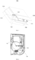
FIG. 1 is a structural schematic diagram of an air conditioner provided in embodiments of the present application; -
FIG. 2 is a sectional view of an air conditioner provided in embodiments of the present application in a power-off state; -
FIG. 3 is a sectional view of an air conditioner provided in embodiments of the present application in a heating mode; and -
FIG. 4 is a sectional view of an air conditioner provided in embodiments of the present application in a cooling mode. - Description of reference signs: 100. air conditioner; 110. housing; 111. air outlet; 113. rotating portion; 130. outer air guide plate; 131. rotating shaft; 150. inner air guide plate; 151. rotating crank arm.
- In order to make the above objectives, features and advantages of the present application more obvious and understandable, the present application is further described in detail below with reference to
FIGS. 1-4 . - Embodiments of the present application provide an air conditioner. With reference to
FIG. 1 , anair conditioner 100 includes ahousing 110 and an outerair guide plate 130, wherein thehousing 110 is provided with anair outlet 111, the outerair guide plate 130 is rotatably provided on an outer wall of thehousing 110, so as to guide output air of theair outlet 111, and the outerair guide plate 130 is provided at a position corresponding to a position of theair outlet 111. One side of the outerair guide plate 130 is provided with a rotatingshaft 131, wherein the rotatingshaft 131 is provided outside theair outlet 111 and is located above theair outlet 111, and the outerair guide plate 130 is rotatably provided on the outer wall of thehousing 110 via the rotatingshaft 131. In the above, a length of the outerair guide plate 130 is greater than that of theair outlet 111 and/or a width of the outerair guide plate 130 is greater than that of theair outlet 111. - The outer
air guide plate 130 is rotatably provided on the outer wall of thehousing 110, a rotation process and a rotation angle thereof are visible, and a user can quickly determine whether an air guide angle of the outerair guide plate 130 is adjusted in place. Moreover, as the outerair guide plate 130 is provided outside theair outlet 111, a size thereof is not restricted by a size of theair outlet 111, and the outer air guide plate can be adjusted to have a larger size, so as to obtain a better air guiding effect. Since the length and/or width of the outerair guide plate 130 are greater than the length and/or width of theair outlet 111, the outerair guide plate 130 may completely shield theair outlet 111, and airflow of theair outlet 111 may be completely guided by the outerair guide plate 130, thus the outerair guide plate 130 has a superior flow guiding effect, and when theair conditioner 100 is not used, dust entering theair outlet 111 may be reduced, and service life of theair conditioner 100 is prolonged. - A rotating
portion 113 is provided on the outer wall of thehousing 110 at a position corresponding to above theair outlet 111, and the rotatingshaft 131 is rotatably fitted with the rotatingportion 113. In the present embodiment, in order to improve rotation tightness of the outerair guide plate 130 and prevent generation of condensation on the outer wall of thehousing 110. The rotatingportion 113 is provided with a groove, and therotating shaft 131 provided on the outerair guide plate 130 is embedded in the groove and is rotatably fitted with the groove. - By providing the
rotating shaft 131 and the groove, the outerair guide plate 130, when rotating, is always tightly arranged in the groove, and the output air of theair outlet 111 is guided along the outerair guide plate 130, and is not easy to contact the outer wall of thehousing 110 from a rotation position. - In order to further improve a utilization rate of the outer
air guide plate 130, in the present embodiment, the groove is connected to an upper edge of theair outlet 111 and is parallel to an extension direction of the upper edge of theair outlet 111. The groove being connected to and extending in parallel with the upper edge of theair outlet 111 ensures that the outerair guide plate 130, after mounted to the groove, has air guiding effect in a wider area, which further improves an air-guiding utilization rate of the outerair guide plate 130. - In order to ensure that the outer
air guide plate 130, after mounted to the groove, can fully cover thehousing 110 in a horizontal direction, which avoids an uncovered region where a gap is generated on a surface of thehousing 110 to cause generation of condensation. In the present embodiment, one end of the groove is formed on an end wall of one end of thehousing 110 in the horizontal direction, and the other end of the groove extends to an end wall of the other end of thehousing 110 in the horizontal direction. That is, the groove penetrates through two ends of thehousing 110 in the horizontal direction. - After the outer
air guide plate 130 is mounted to the groove, in order to implement smooth rotation, and further ensure tight fit between the outerair guide plate 130 and thehousing 110 so as to prevent generation of a too big gap, in the present embodiment, a cross section of the groove is in a semi-circular arc shape. - The
rotating shaft 131 is embedded in the groove, so as to realize rotatable fit between the outerair guide plate 130 and thehousing 110. As the groove is recessed in the outer wall of thehousing 110, outward protruding of the joint of the outerair guide plate 130 and thehousing 110 is avoided, thus improving an overall aesthetic degree of theair conditioner 100. - In order to ensure the anti-condensation effect, lengths of the
rotating shaft 131 and the outerair guide plate 130 are both corresponding to the length of the groove, and are both greater than the length of theair outlet 111. That is, in cases where therotating shaft 131 is embedded in the groove, two ends of therotating shaft 131 are coplanar with end walls of the two ends of the groove respectively, and two ends of the outerair guide plate 130 in the length direction are coplanar with the end walls of the two ends of the groove, respectively. - Referring to
FIG. 1 , theair conditioner 100 further includes an air guide mechanism, wherein the air guide mechanism is provided on thehousing 110, and the air guide mechanism and the outerair guide plate 130 jointly form an air guide channel capable of changing a wind direction of the output air, so as to guide the output air of theair outlet 111. In the prior art, a wind direction is fixed in a direction of theair outlet 111, and the output air is only guided by the outerair guide plate 130, without changing the wind direction. By providing the air guide mechanism, the air guide mechanism cooperates with the outerair guide plate 130, so that the wind direction may be changed to a direction showing the best effect, and theair conditioner 100 may achieve the best effect when used, and comply with use requirements of users. - The air guide mechanism includes an inner
air guide plate 150, wherein the innerair guide plate 150 is rotatably provided on thehousing 110, and the outerair guide plate 130 and the innerair guide plate 150 are used to jointly form the air guide channel, so as to guide the output air of theair outlet 111. The outerair guide plate 130 and the innerair guide plate 150 cooperate with each other. The innerair guide plate 150 may flexibly rotate along with the outerair guide plate 130, so as to achieve the purpose of changing the wind direction. - The inner
air guide plate 150 is rotatably provided on a side wall inside theair outlet 111 and away from the outerair guide plate 130. One side of the innerair guide plate 150 is provided with arotating crank arm 151, wherein one end of the rotating crankarm 151 away from the innerair guide plate 150 is rotatably connected to the side wall inside theair outlet 111 and away from the outerair guide plate 130. Therotating crank arm 151 increases a rotation angle range of the innerair guide plate 150, so that the innerair guide plate 150 can completely rotate out of theair outlet 111, so as to obtain a larger air guide angle. - Referring to
FIG. 2 , a maximum air shielding area of the outerair guide plate 130 is greater than a maximum air shielding area of the innerair guide plate 150. In a power-off state of theair conditioner 100, the innerair guide plate 150 is received in theair outlet 111, and the outerair guide plate 130 shields theair outlet 111, so that the outerair guide plate 130 and the innerair guide plate 150 are less likely to interfere with each other, and meanwhile have a certain protection effect on the innerair guide plate 150 in the power-off state. - With reference to
FIG. 2 andFIG. 3 , the outerair guide plate 130 and the innerair guide plate 150 are both provided in an arc shape. When theair conditioner 100 operates in a heating mode from the power-off state, the innerair guide plate 150 rotates to the outside of theair outlet 111, the outerair guide plate 130 rotates at a first angle, and the outerair guide plate 130 and the innerair guide plate 150 form an inclined downward air guide channel, so that the airflow blown out from theair outlet 111 obliquely flows downwards along a side of the outerair guide plate 130 close to the innerair guide plate 150, and in this case, a concave arc surface of the outerair guide plate 130 is opposite to a concave arc surface of the innerair guide plate 150. The outerair guide plate 130 and the innerair guide plate 150 are both provided in an arc shape. The concave surface of the outerair guide plate 130 faces one side of the outerair guide plate 130 close to theair outlet 111, and the concave surface of the innerair guide plate 150 faces one side of the innerair guide plate 150 close to theair outlet 111. - In the prior art, the air guide plate is provided in the
air outlet 111, an air guiding size thereof is restricted by the size of theair outlet 111, and the flow guiding effect on the output air is limited. During the operation of theair conditioner 100 in the heating mode, hot air will immediately float upwards after being blown out from theair outlet 111, which results in a large amount of hot air being gathered in an upper space of a room, causing the user to feel that the head is hot and feet are cold, such that the heating effect on the whole room is poor. In the present embodiment, the outerair guide plate 130 is provided outside thehousing 110, the size thereof is not restricted by the size of theair outlet 111, and all the output air of the air outlet may be guided, thus the pressing down effect on the hot air is better, and the heating effect on the whole room is better. Moreover, the outerair guide plate 130 is an arc-shaped plate, with end hanging down, and has a better pressing down effect on the hot air. - With reference to
FIG. 2 to FIG. 4 , when theair conditioner 100 operates in a cooling mode from the power-off state, the innerair guide plate 150 rotates to the outside of theair outlet 111, the outerair guide plate 130 rotates at a second angle, in this case, the concave arc surface of the outerair guide plate 130 is opposite to the concave arc surface of the innerair guide plate 150, and the outerair guide plate 130 and the innerair guide plate 150 form an approximately horizontal air guide channel, where the second angle is greater than the first angle. - As the hot air and the cold air have different airflow distributions, the cold air needs to be transported farther in order to achieve a better cooling effect. By providing the outer
air guide plate 130 outside thehousing 110, the size of the outer air guide plate is not restricted by the size of theair outlet 111, and then the outer air guide plate may be provided to be longer in size, so as to ensure that the cold air can be blown farther, and improve the cooling effect. In the cooling mode, as the innerair guide plate 150 is an arc-shaped plate, with ends upturned, it is more conducive to long-distance transport of the cold air. - In conclusion, in practical application of the
air conditioner 100 provided in the present embodiment, as the outerair guide plate 130 is provided on the outer wall of thehousing 110, the rotation process and the rotation angle thereof are visible, and the user can quickly determine whether the outerair guide plate 130 is adjusted in place by observing with naked eyes when adjusting the air guide angle, so that the user obtains a good use feeling. Moreover, by providing the outerair guide plate 130 outside theair outlet 111, the outer air guide plate may be adjusted to a larger size, so as to obtain a better air guiding effect and prevent generation of condensation. - The implementation principle of the embodiments of the present application is as follows: when the
air conditioner 100 needs to be used, theair conditioner 100 is turned on, in this case, the outerair guide plate 130 rotates to open, and after the outerair guide plate 130 is opened, the innerair guide plate 150 rotates to open, so that the air guide channel between the outerair guide plate 130 and the innerair guide plate 150 is opened. During the operation of the heating mode, the outerair guide plate 130 and the innerair guide plate 150 rotate to form a hot air down-pressing channel, so that the airflow blown out from theair outlet 111 flows obliquely downwards, thereby rendering a better heating effect. During the operation of the cooling mode, the outerair guide plate 130 and the innerair guide plate 150 rotate to form a cold air up-rising channel, so that the airflow blown out from the air outlet may transport cold air over a long distance, thereby rendering a better cooling effect. After the use is completed, theair conditioner 100 is turned off, and in this case, first the innerair guide plate 150 rotates back into thehousing 110, and then the outerair guide plate 130 rotates to cover at theair outlet 111. - The above are all preferred embodiments of the present application, but the scope of protection of the present application is not limited thereby, so: equivalent variations in structure, shape, and principle of the present application should be covered within the scope of protection of the present application.
Claims (12)
- An air conditioner, characterized by comprising a housing (110) and an outer air guide plate (130), wherein the housing (110) is provided with an air outlet (111), the outer air guide plate (130) is rotatably provided on an outer wall of the housing (110) at a position corresponding to the air outlet (111), so as to guide output air of the air outlet (111), one side of the outer air guide plate (130) is provided with a rotating shaft (131), the rotating shaft (131) is provided outside the air outlet (111) and is located above the air outlet (111), and the outer air guide plate (130) is rotatably provided on the outer wall of the housing (110) via the rotating shaft (131).
- The air conditioner according to claim 1, wherein a rotating portion (113) is provided on the outer wall of the housing (110) at a position corresponding to above the air outlet (111), and the rotating shaft (131) is rotatably fitted with the rotating portion (113).
- The air conditioner according to claim 1, wherein a length of the outer air guide plate (130) is greater than a length of the air outlet (111), and/or a width of the outer air guide plate (130) is greater than a width of the air outlet (111).
- The air conditioner according to claim 1, further comprising an air guide mechanism, wherein the air guide mechanism is provided on the housing (110), and the air guide mechanism and the outer air guide plate (130) jointly form an air guide channel configured for changing a wind direction of the output air, so as to guide the output air of the air outlet (111).
- The air conditioner according to claim 4, wherein the air guide mechanism comprises an inner air guide plate (150), the inner air guide plate (150) is rotatably provided on the housing (110), and the outer air guide plate (130) and the inner air guide plate (150) are configured to jointly form the air guide channel, so as to guide the output air of the air outlet (111).
- The air conditioner according to claim 5, wherein the inner air guide plate (150) is rotatably provided on a side wall inside the air outlet (111) and away from the outer air guide plate (130).
- The air conditioner according to claim 5, wherein one side of the inner air guide plate (150) is provided with a rotating crank arm (151), one end of the rotating crank arm (151) away from the inner air guide plate (150) is rotatably connected to a side wall inside the air outlet (111) and away from the outer air guide plate (130), and the rotating crank arm (151) is configured to drive the inner air guide plate (150) to rotate inside and outside the air outlet (111).
- The air conditioner according to any one of claims 5-7, wherein a maximum shielding area of the outer air guide plate (130) is greater than a maximum shielding area of the inner air guide plate (150).
- The air conditioner according to claim 8, wherein when the air conditioner (100) is in a power-off state, the inner air guide plate (150) is received in the air outlet (111), and the outer air guide plate (130) shields the air outlet (111) outside the air outlet (111).
- The air conditioner according to claim 9, wherein when the air conditioner (100) operates in a heating mode from the power-off state, the inner air guide plate (150) rotates to the outside of the air outlet (111), and the outer air guide plate (130) rotates at a first angle, so as to guide airflow blown out from the air outlet (111) to flow obliquely downwards.
- The air conditioner according to claim 9, wherein when the air conditioner (100) operates in a cooling mode from the power-off state, the inner air guide plate (150) rotates to the outside of the air outlet (111), and the outer air guide plate (130) rotates at a second angle, wherein the second angle is greater than the first angle.
- The air conditioner according to claim 1, wherein the outer air guide plate (130) and the inner air guide plate (150) of the air conditioner are both provided in an arc shape, and when operating in a working mode, a concave arc surface of the outer air guide plate (130) is opposite to a concave arc surface of the inner air guide plate (150).
Applications Claiming Priority (2)
| Application Number | Priority Date | Filing Date | Title |
|---|---|---|---|
| CN202111013187.5A CN115727407A (en) | 2021-08-31 | 2021-08-31 | Indoor unit and air conditioner |
| PCT/CN2022/116336 WO2023030415A1 (en) | 2021-08-31 | 2022-08-31 | Air conditioner |
Publications (4)
| Publication Number | Publication Date |
|---|---|
| EP4397915A1 true EP4397915A1 (en) | 2024-07-10 |
| EP4397915A4 EP4397915A4 (en) | 2024-11-13 |
| EP4397915C0 EP4397915C0 (en) | 2025-11-26 |
| EP4397915B1 EP4397915B1 (en) | 2025-11-26 |
Family
ID=83688533
Family Applications (1)
| Application Number | Title | Priority Date | Filing Date |
|---|---|---|---|
| EP22863550.4A Active EP4397915B1 (en) | 2021-08-31 | 2022-08-31 | Air conditioner |
Country Status (5)
| Country | Link |
|---|---|
| EP (1) | EP4397915B1 (en) |
| JP (1) | JP7801067B2 (en) |
| CN (2) | CN115727407A (en) |
| AU (1) | AU2022336920B2 (en) |
| WO (1) | WO2023030415A1 (en) |
Families Citing this family (1)
| Publication number | Priority date | Publication date | Assignee | Title |
|---|---|---|---|---|
| CN121206662A (en) * | 2024-06-26 | 2025-12-26 | 美的集团股份有限公司 | Air conditioner control methods and air conditioners |
Family Cites Families (27)
| Publication number | Priority date | Publication date | Assignee | Title |
|---|---|---|---|---|
| JP4237238B1 (en) * | 2007-09-07 | 2009-03-11 | シャープ株式会社 | Air conditioner |
| JP5080210B2 (en) | 2007-11-09 | 2012-11-21 | シャープ株式会社 | Air conditioner |
| JP2010101504A (en) * | 2008-10-21 | 2010-05-06 | Panasonic Corp | Air conditioner |
| CN103673084B (en) * | 2012-09-24 | 2016-05-04 | 珠海格力电器股份有限公司 | Air conditioner indoor unit, air conditioner with air conditioner indoor unit and control method of indoor unit |
| CN104075376B (en) * | 2013-03-29 | 2017-06-06 | 海尔集团公司 | Wall-hanging indoor unit of air conditioner |
| CN104110724B (en) * | 2013-04-17 | 2018-04-17 | 珠海格力电器股份有限公司 | Wall-mounted air conditioner |
| CN105091082A (en) * | 2014-04-16 | 2015-11-25 | 海信科龙电器股份有限公司 | Wall-mounting air conditioner indoor unit, wall-mounting air conditioner, and air blowing control method |
| CN104697058B (en) * | 2015-02-13 | 2017-06-27 | 广东美的制冷设备有限公司 | Indoor apparatus of air conditioner and its control method |
| CN104697059A (en) * | 2015-02-13 | 2015-06-10 | 广东美的制冷设备有限公司 | Indoor unit of air conditioner and control method of indoor unit |
| JP2016153717A (en) * | 2015-02-18 | 2016-08-25 | 三星電子株式会社Samsung Electronics Co.,Ltd. | Ceiling embedded type indoor machine and air conditioner using the same |
| JP6648988B2 (en) * | 2015-06-02 | 2020-02-19 | シャープ株式会社 | Air conditioner |
| CN205579920U (en) * | 2016-04-15 | 2016-09-14 | 珠海格力电器股份有限公司 | Inner unit of air conditioner and its air guiding structure |
| KR101890869B1 (en) * | 2016-10-27 | 2018-08-22 | 삼성전자주식회사 | Air Conditioner |
| CN106678979B (en) * | 2017-01-20 | 2022-06-21 | 珠海格力电器股份有限公司 | Air conditioner |
| CN207268480U (en) * | 2017-06-09 | 2018-04-24 | 青岛海尔空调器有限总公司 | Wall-hanging air conditioner indoor unit |
| CN107477691A (en) * | 2017-09-12 | 2017-12-15 | 广东美的制冷设备有限公司 | Wall indoor unit and air conditioner |
| CN207936279U (en) * | 2018-02-05 | 2018-10-02 | 青岛海尔空调器有限总公司 | Air conditioner indoor unit |
| CN108488907B (en) * | 2018-03-20 | 2024-08-27 | 广东美的制冷设备有限公司 | Air Conditioner |
| CN208418970U (en) | 2018-05-14 | 2019-01-22 | 青岛海尔空调器有限总公司 | Air conditioner indoor unit |
| CN109974089B (en) * | 2019-04-23 | 2024-05-28 | 广东美的制冷设备有限公司 | Wall-mounted indoor unit and air conditioner |
| CN210951781U (en) | 2019-07-31 | 2020-07-07 | 宁波奥克斯电气股份有限公司 | Air-conditioning wind deflector and air conditioner |
| JP7417380B2 (en) * | 2019-08-19 | 2024-01-18 | シャープ株式会社 | Air conditioner indoor unit and air conditioner |
| CN212108670U (en) * | 2019-12-30 | 2020-12-08 | 海信(广东)空调有限公司 | Air conditioner indoor unit |
| EP4086532B1 (en) * | 2019-12-30 | 2025-01-15 | Hisense (Guangdong) Air Conditioning Co., Ltd. | Air conditioner indoor unit |
| CN111351130A (en) * | 2020-03-26 | 2020-06-30 | 青岛海尔空调器有限总公司 | Air conditioner indoor unit |
| CN111503742A (en) * | 2020-05-14 | 2020-08-07 | 青岛海尔空调器有限总公司 | Wall-mounted air conditioner indoor unit |
| CN215929800U (en) * | 2021-08-31 | 2022-03-01 | 宁波奥克斯电气股份有限公司 | Indoor unit and air conditioner |
-
2021
- 2021-08-31 CN CN202111013187.5A patent/CN115727407A/en active Pending
- 2021-08-31 CN CN202211023575.6A patent/CN115234979B/en active Active
-
2022
- 2022-08-31 JP JP2024510307A patent/JP7801067B2/en active Active
- 2022-08-31 EP EP22863550.4A patent/EP4397915B1/en active Active
- 2022-08-31 WO PCT/CN2022/116336 patent/WO2023030415A1/en not_active Ceased
- 2022-08-31 AU AU2022336920A patent/AU2022336920B2/en active Active
Also Published As
| Publication number | Publication date |
|---|---|
| EP4397915A4 (en) | 2024-11-13 |
| CN115234979A (en) | 2022-10-25 |
| EP4397915C0 (en) | 2025-11-26 |
| JP7801067B2 (en) | 2026-01-16 |
| AU2022336920A1 (en) | 2024-02-22 |
| WO2023030415A9 (en) | 2024-02-29 |
| CN115234979B (en) | 2024-04-12 |
| JP2024529757A (en) | 2024-08-08 |
| EP4397915B1 (en) | 2025-11-26 |
| WO2023030415A1 (en) | 2023-03-09 |
| CN115727407A (en) | 2023-03-03 |
| AU2022336920B2 (en) | 2025-10-09 |
Similar Documents
| Publication | Publication Date | Title |
|---|---|---|
| CN207880963U (en) | Air conditioner indoor unit and air conditioner | |
| CN113048569B (en) | Indoor unit, air conditioner and control method of air conditioner | |
| CN108317598B (en) | Wall-mounted air conditioner indoor unit | |
| CN219868133U (en) | Air conditioner hanging machine | |
| EP4397915B1 (en) | Air conditioner | |
| CN215929800U (en) | Indoor unit and air conditioner | |
| CN214700994U (en) | Air conditioner air outlet device and air conditioner | |
| CN207936254U (en) | Wall-hanging air conditioner indoor unit | |
| CN207936280U (en) | Air conditioner indoor unit | |
| CN222187131U (en) | Air conditioner | |
| CN216203763U (en) | Indoor unit and air conditioner with same | |
| CN113959006B (en) | Indoor unit, air conditioner and control method of indoor unit | |
| CN222187126U (en) | Air Conditioner | |
| CN222187135U (en) | Air conditioner | |
| CN222187132U (en) | Air conditioner | |
| CN222187127U (en) | Air Conditioner | |
| CN222187130U (en) | Air conditioner | |
| CN219797356U (en) | Indoor unit and air conditioner | |
| CN222187128U (en) | Air Conditioner | |
| CN222187125U (en) | Air conditioner | |
| CN106679141B (en) | Air deflector assembly of indoor hanging machine of air conditioner and indoor hanging machine of air conditioner | |
| CN222187133U (en) | Air conditioner | |
| CN222187129U (en) | Air Conditioner | |
| CN222187134U (en) | Air conditioner | |
| CN218820658U (en) | Air conditioner indoor unit and air conditioner |
Legal Events
| Date | Code | Title | Description |
|---|---|---|---|
| STAA | Information on the status of an ep patent application or granted ep patent |
Free format text: STATUS: THE INTERNATIONAL PUBLICATION HAS BEEN MADE |
|
| PUAI | Public reference made under article 153(3) epc to a published international application that has entered the european phase |
Free format text: ORIGINAL CODE: 0009012 |
|
| STAA | Information on the status of an ep patent application or granted ep patent |
Free format text: STATUS: REQUEST FOR EXAMINATION WAS MADE |
|
| 17P | Request for examination filed |
Effective date: 20240205 |
|
| AK | Designated contracting states |
Kind code of ref document: A1 Designated state(s): AL AT BE BG CH CY CZ DE DK EE ES FI FR GB GR HR HU IE IS IT LI LT LU LV MC MK MT NL NO PL PT RO RS SE SI SK SM TR |
|
| STAA | Information on the status of an ep patent application or granted ep patent |
Free format text: STATUS: EXAMINATION IS IN PROGRESS |
|
| A4 | Supplementary search report drawn up and despatched |
Effective date: 20241010 |
|
| RIC1 | Information provided on ipc code assigned before grant |
Ipc: F24F 13/14 20060101ALI20241004BHEP Ipc: F24F 13/10 20060101ALI20241004BHEP Ipc: F24F 11/79 20180101ALI20241004BHEP Ipc: F24F 1/0011 20190101AFI20241004BHEP |
|
| 17Q | First examination report despatched |
Effective date: 20241022 |
|
| DAV | Request for validation of the european patent (deleted) | ||
| DAX | Request for extension of the european patent (deleted) | ||
| GRAP | Despatch of communication of intention to grant a patent |
Free format text: ORIGINAL CODE: EPIDOSNIGR1 |
|
| STAA | Information on the status of an ep patent application or granted ep patent |
Free format text: STATUS: GRANT OF PATENT IS INTENDED |
|
| INTG | Intention to grant announced |
Effective date: 20250709 |
|
| GRAS | Grant fee paid |
Free format text: ORIGINAL CODE: EPIDOSNIGR3 |
|
| GRAA | (expected) grant |
Free format text: ORIGINAL CODE: 0009210 |
|
| STAA | Information on the status of an ep patent application or granted ep patent |
Free format text: STATUS: THE PATENT HAS BEEN GRANTED |
|
| AK | Designated contracting states |
Kind code of ref document: B1 Designated state(s): AL AT BE BG CH CY CZ DE DK EE ES FI FR GB GR HR HU IE IS IT LI LT LU LV MC MK MT NL NO PL PT RO RS SE SI SK SM TR |
|
| REG | Reference to a national code |
Ref country code: CH Ref legal event code: F10 Free format text: ST27 STATUS EVENT CODE: U-0-0-F10-F00 (AS PROVIDED BY THE NATIONAL OFFICE) Effective date: 20251126 Ref country code: GB Ref legal event code: FG4D |
|
| REG | Reference to a national code |
Ref country code: IE Ref legal event code: FG4D |
|
| U01 | Request for unitary effect filed |
Effective date: 20251126 |
|
| U07 | Unitary effect registered |
Designated state(s): AT BE BG DE DK EE FI FR IT LT LU LV MT NL PT RO SE SI Effective date: 20251201 |
|
| REG | Reference to a national code |
Ref country code: CH Ref legal event code: W10 Free format text: ST27 STATUS EVENT CODE: U-0-0-W10-W00 (AS PROVIDED BY THE NATIONAL OFFICE) Effective date: 20260409 |
|
| PG25 | Lapsed in a contracting state [announced via postgrant information from national office to epo] |
Ref country code: ES Free format text: LAPSE BECAUSE OF FAILURE TO SUBMIT A TRANSLATION OF THE DESCRIPTION OR TO PAY THE FEE WITHIN THE PRESCRIBED TIME-LIMIT Effective date: 20251126 |
|
| PG25 | Lapsed in a contracting state [announced via postgrant information from national office to epo] |
Ref country code: NO Free format text: LAPSE BECAUSE OF FAILURE TO SUBMIT A TRANSLATION OF THE DESCRIPTION OR TO PAY THE FEE WITHIN THE PRESCRIBED TIME-LIMIT Effective date: 20260226 |
|
| PG25 | Lapsed in a contracting state [announced via postgrant information from national office to epo] |
Ref country code: HR Free format text: LAPSE BECAUSE OF FAILURE TO SUBMIT A TRANSLATION OF THE DESCRIPTION OR TO PAY THE FEE WITHIN THE PRESCRIBED TIME-LIMIT Effective date: 20251126 |
|
| PG25 | Lapsed in a contracting state [announced via postgrant information from national office to epo] |
Ref country code: RS Free format text: LAPSE BECAUSE OF FAILURE TO SUBMIT A TRANSLATION OF THE DESCRIPTION OR TO PAY THE FEE WITHIN THE PRESCRIBED TIME-LIMIT Effective date: 20260226 |
|
| PG25 | Lapsed in a contracting state [announced via postgrant information from national office to epo] |
Ref country code: IS Free format text: LAPSE BECAUSE OF FAILURE TO SUBMIT A TRANSLATION OF THE DESCRIPTION OR TO PAY THE FEE WITHIN THE PRESCRIBED TIME-LIMIT Effective date: 20260326 |
|
| PG25 | Lapsed in a contracting state [announced via postgrant information from national office to epo] |
Ref country code: PL Free format text: LAPSE BECAUSE OF FAILURE TO SUBMIT A TRANSLATION OF THE DESCRIPTION OR TO PAY THE FEE WITHIN THE PRESCRIBED TIME-LIMIT Effective date: 20251126 |
|
| RAP4 | Party data changed (patent owner data changed or rights of a patent transferred) |
Owner name: NINGBO AUX ELECTRIC CO., LTD. Owner name: AUX AIR CONDITIONER CO., LTD |
|
| PG25 | Lapsed in a contracting state [announced via postgrant information from national office to epo] |
Ref country code: SM Free format text: LAPSE BECAUSE OF FAILURE TO SUBMIT A TRANSLATION OF THE DESCRIPTION OR TO PAY THE FEE WITHIN THE PRESCRIBED TIME-LIMIT Effective date: 20251126 |
|
| PG25 | Lapsed in a contracting state [announced via postgrant information from national office to epo] |
Ref country code: CZ Free format text: LAPSE BECAUSE OF FAILURE TO SUBMIT A TRANSLATION OF THE DESCRIPTION OR TO PAY THE FEE WITHIN THE PRESCRIBED TIME-LIMIT Effective date: 20251126 |
|
| PG25 | Lapsed in a contracting state [announced via postgrant information from national office to epo] |
Ref country code: SK Free format text: LAPSE BECAUSE OF FAILURE TO SUBMIT A TRANSLATION OF THE DESCRIPTION OR TO PAY THE FEE WITHIN THE PRESCRIBED TIME-LIMIT Effective date: 20251126 |