EP4397897A1 - Sliding connector pipe assembly - Google Patents
Sliding connector pipe assembly Download PDFInfo
- Publication number
- EP4397897A1 EP4397897A1 EP23215561.4A EP23215561A EP4397897A1 EP 4397897 A1 EP4397897 A1 EP 4397897A1 EP 23215561 A EP23215561 A EP 23215561A EP 4397897 A1 EP4397897 A1 EP 4397897A1
- Authority
- EP
- European Patent Office
- Prior art keywords
- sliding connector
- displacement
- assembly
- sliding
- pipe
- Prior art date
- Legal status (The legal status is an assumption and is not a legal conclusion. Google has not performed a legal analysis and makes no representation as to the accuracy of the status listed.)
- Granted
Links
Images






Classifications
-
- F—MECHANICAL ENGINEERING; LIGHTING; HEATING; WEAPONS; BLASTING
- F16—ENGINEERING ELEMENTS AND UNITS; GENERAL MEASURES FOR PRODUCING AND MAINTAINING EFFECTIVE FUNCTIONING OF MACHINES OR INSTALLATIONS; THERMAL INSULATION IN GENERAL
- F16L—PIPES; JOINTS OR FITTINGS FOR PIPES; SUPPORTS FOR PIPES, CABLES OR PROTECTIVE TUBING; MEANS FOR THERMAL INSULATION IN GENERAL
- F16L27/00—Adjustable joints; Joints allowing movement
- F16L27/12—Adjustable joints; Joints allowing movement allowing substantial longitudinal adjustment or movement
- F16L27/127—Adjustable joints; Joints allowing movement allowing substantial longitudinal adjustment or movement with means for locking the longitudinal adjustment or movement in the final mounted position
- F16L27/1273—Adjustable joints; Joints allowing movement allowing substantial longitudinal adjustment or movement with means for locking the longitudinal adjustment or movement in the final mounted position by quick-acting means
-
- A—HUMAN NECESSITIES
- A01—AGRICULTURE; FORESTRY; ANIMAL HUSBANDRY; HUNTING; TRAPPING; FISHING
- A01C—PLANTING; SOWING; FERTILISING
- A01C7/00—Sowing
- A01C7/08—Broadcast seeders; Seeders depositing seeds in rows
- A01C7/081—Seeders depositing seeds in rows using pneumatic means
- A01C7/082—Ducts, distribution pipes or details thereof for pneumatic seeders
-
- F—MECHANICAL ENGINEERING; LIGHTING; HEATING; WEAPONS; BLASTING
- F16—ENGINEERING ELEMENTS AND UNITS; GENERAL MEASURES FOR PRODUCING AND MAINTAINING EFFECTIVE FUNCTIONING OF MACHINES OR INSTALLATIONS; THERMAL INSULATION IN GENERAL
- F16L—PIPES; JOINTS OR FITTINGS FOR PIPES; SUPPORTS FOR PIPES, CABLES OR PROTECTIVE TUBING; MEANS FOR THERMAL INSULATION IN GENERAL
- F16L25/00—Construction or details of pipe joints not provided for in, or of interest apart from, groups F16L13/00 - F16L23/00
- F16L25/10—Sleeveless joints between two pipes, one being introduced into the other
-
- F—MECHANICAL ENGINEERING; LIGHTING; HEATING; WEAPONS; BLASTING
- F16—ENGINEERING ELEMENTS AND UNITS; GENERAL MEASURES FOR PRODUCING AND MAINTAINING EFFECTIVE FUNCTIONING OF MACHINES OR INSTALLATIONS; THERMAL INSULATION IN GENERAL
- F16L—PIPES; JOINTS OR FITTINGS FOR PIPES; SUPPORTS FOR PIPES, CABLES OR PROTECTIVE TUBING; MEANS FOR THERMAL INSULATION IN GENERAL
- F16L37/00—Couplings of the quick-acting type
- F16L37/08—Couplings of the quick-acting type in which the connection between abutting or axially overlapping ends is maintained by locking members
- F16L37/12—Couplings of the quick-acting type in which the connection between abutting or axially overlapping ends is maintained by locking members using hooks, pawls, or other movable or insertable locking members
- F16L37/14—Joints secured by inserting between mating surfaces an element, e.g. a piece of wire, a pin, a chain
- F16L37/142—Joints secured by inserting between mating surfaces an element, e.g. a piece of wire, a pin, a chain where the securing element is inserted tangentially
- F16L37/144—Joints secured by inserting between mating surfaces an element, e.g. a piece of wire, a pin, a chain where the securing element is inserted tangentially the securing element being U-shaped
Definitions
- the traction unit is typically backed up to and coupled with the tilling implement, which in turn is backed up to and coupled with the air cart (e.g., by using respective hitch pins or the like, and assuming that the air cart is behind rather than in front of the air drill). All necessary hydraulic lines, air lines, electrical power lines and/or electrical data lines are then connected between the traction unit, tilling implement and air cart.
- the sliding connector has a coupling end sized to overlap a receiver to fluidly couple the pipe to the receiver when the sliding connector is in the extended displacement.
- the sliding connector has a sliding distance between the retracted displacement and the extended displacement, wherein the sliding distance is sufficient to allow the coupling end to at least partially overlap the receiver when in the extended displacement and the locking mechanism selectively locks the sliding connector in the extended displacement partially overlapping the receiver.
- the locking mechanism has a latch that extends at least partially radially inwardly past the inner connector wall in a latched orientation.
- the latch is deflectable to a released orientation wherein the latch does not substantially extend radially inwardly past the inner connector wall.
- Yet another example of this embodiment includes removing the pipe from the receiver by releasing the locking mechanism by transitioning a wicket to a released orientation on the sliding connector to allow the sliding connector to transition from the extended displacement to the retracted displacement.
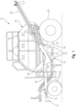
- Figs. 1-2 illustrate a conventional air seeder assembly.
- Fig. 1 is a partial, side schematic view of an agricultural vehicle, and more particularly an air cart 12.
- Air cart 12 is towed by a tilling implement 14 with a portion of a rear hitch 16 illustrated in FIG. 1 .
- the tilling implement 14 is an air drill but can be configured differently in other embodiments.
- the tilling implement 14 includes a planter and the air cart 12 can be used to refill mini-hoppers on the planter.
- Air cart 12 can also include a rear hitch allowing air cart 12 to be towed in front of, rather than behind, tilling implement 14.
- air lines 36 may be primary air lines that selectively direct fluid from the tank 24 to the remaining portions of the pneumatic distribution system 38.
- the primary air lines 36 may typically be installed after the tank 24, metering system 27, and manifold 52 are installed on the air cart 12. As such, the primary air lines 36 must be able to be removeably coupled between two substantially fixed locations. Further, often a user needs to remove the primary air line 36 to service the air cart 12 or fix a clog or other issue with the primary air line 36.
- the sliding connector 300 is sized to slide along the pipe 302 a sliding distance 306 between a latched orientation 402 wherein the sliding connector 300 is extended relative to a distal end 410 of the pipe 302 and a released orientation 404 wherein the sliding connector 300 can be transitioned to a collapsed configuration wherein the sliding connector 300 extends a retracted displacement 406 from the distal end 410 of the pipe 302.
- the sliding connector 300 may have indicia 322 thereon the provides an indication of the proper orientation of the sliding connector 300 with reference to the air flow direction of the pneumatic distribution system 32.
- the sliding connector 300 may have a locking mechanism 310 that utilizes the latch 308 to selectively maintain the sliding connector 300 in the latched orientation 402. More specifically, the latch 308 may be naturally biased at least partially radially inward of an inner connector wall 412 of a body 414 of the sliding connector 300. With this configuration, when the sliding connector 300 is moved the extended displacement 408 from the distal end 410, the locking mechanism 310 may engaged the distal end 310 as the latch 308 naturally biases radially inward to the latched orientation 402 as the latch 308 is no longer positioned along the radially outer surface of the pipe 302.
- the latch 308 may contact the distal end 410 of the pipe 302 when a force is applied to the sliding connector 300 towards the pipe 302.
- the contact between the latch 308 and the distal end 410 of the pipe 302 may be sufficient to substantially maintain the sliding connector 300 in the extended displacement 408 even when forces act on the sliding connector 300 towards the pipe 302.
- the locking mechanism 310 may be elastically deformable to selectively transition the latch 308 to the released orientation 404 wherein the latch 308 does not substantially contact the distal end 410 of the pipe 302. More specifically, the locking mechanism 310 may have a pushing surface 312 wherein a user may apply a push force PF to the locking mechanism 310 to transition the latch 308 from the latched orientation 402 to the released orientation 404.
- the push force PF may be such that an average adult can apply the push force PF with only a finger or thumb. In other words, the push force PF can be applied by a user without the use of additional tools. More specifically, the user may use a finger or similar object to press the pushing surface 412 to draw the latch 308 radially away from the tube 302. Once the latch 308 is sufficiently spaced from the distal end 410 of the tube 302, the sliding connector 300 can transition from the latched orientation 402 to the released orientation 404.
- the latch 308 may have an angled profile. In this configuration, the latch 308 may easily slide along the sliding distance 306 towards the extended displacement 408. However, the latch 308 may inhibit movement towards the retracted displacement 406 unless the pushing surface 312 is engaged to bias the latch 308 away from the radially external surface of the pipe 302.
- the locking mechanism 310 may be formed from a cutout 314 through a portion of the sliding connector 300.
- the cutout 314 may be substantially U-shaped. However, other shapes are considered herein. This configuration may allow the latch 308 to be selectively deflected away from the pipe 302 while staying connected to the sliding connector 300. Further still, this configuration allows the locking mechanism 310 to be formed from the same material as the remaining components of the sliding connector 300.
- the locking mechanism 310 may also have a stiffening support 316.
- the stiffening support 316 may run from the pushing surface 412 towards the pipe receiving end 303 at least partially between portions of the cutout 314.
- the stiffening support 316 may provide a reinforcement to the latch 308 to alter the pushing force PF required on the pushing surface 312 to transition the latch 308 to the released orientation.
- the width of the stiffening support 316 may be selected to provide the desired stiffening effect on the latch 308. More specifically, a wider stiffening support 316 may require a greater pushing force PF on the pushing surface 312 to transition the latch 308 to the released orientation compared to a relatively thinner stiffening support 316.
- the cutout 314 may have a gap that can be filled or otherwise covered with a deflectable seal 320. More specifically, the gap in the sliding connector 300 created by the cutout 314 may be filled with the deflectable seal 320 which may be a material that prevents fluid from transition from a radially inner portion of the sliding connector 300 to a radially outer portion of the inner connector 300 through the gap. This may prevent any commodity or air flow from exiting the pneumatic system 27 through the cutout 314.
- the deflectable seal 320 may be in or over the cutout 314 and may be malleable such that the locking mechanism 310 can still transition the latch 308 between the latched orientation 402 to the released orientation 404 without tearing or otherwise compromising the material in or over the cutout 314.
- the material in or over the gap 320 of the cutout 314 allows the locking mechanism 310 to function as described herein while maintaining a fluid seal along the cutout 314.
- the sliding connector 300 may be in the retracted displacement 406 and the coupling end 304 aligned with a receiver 602 in configuration 600.
- the locking assembly 310 is in the released orientation 404 and the sliding connector 300 can slide relative to the pipe 302 axially along axis 604.
- the sliding connector 300 may be slid axially relative to the pipe 302 to the extended displacement 408 as illustrated in an extended configuration 601 of Fig. 6b .
- the coupling end 304 is fluidly coupled to the receiver 602 as the latch 308 engages the distal end 410 of the pipe 302 to selectively hold the sliding connector 300 in the extended configuration 601.
- the latch 308 engages any portion of the distal end 410 of the pipe 302 such that the sliding connector 300 can be any angular orientation about the axis 604 and still be locked in the extended configuration by the latch 308. That is to say, the sliding connector 300 can be rotated about the axis 604 and the latch 308 will still properly engage the distal end 410 of the pipe 302. In one aspect this feature may allow the user to position the locking mechanism 310 at an easily accessible location because the sliding connector 300 can be rotated relative to the tube 302 without affect the functionality discussed herein.
- the sliding connector 700 may provide similar advantages as the sliding connector 300 in that the sliding connector 700 has a pipe receiving end 702 sized to slidably fit over a pipe 302 such as a conveyance tube or the like.
- the sliding connector 700 is selectably transitionable between a locked orientation 802 and a released orientation 804. Also similar to the sliding connector 300, the sliding connector 700 can be positioned by a user in either the locked orientation or the released orientation without the use of tools.
- a locking mechanism 706 may have a wicket 708 with two ends positioned in parallel through holes 808a, 808b, the wicket 708 being in a spaced configuration 806 from the sliding connector 700.
- the wicket 708 may be partially positioned within the through holes 808a, 808b such that the wicket 708 is not be occupying tangential pathways 810a, 810b of the sliding connector 700 defined in part by the through holes 808a, 808b.
- the tangential pathways 810a, 810b are positioned along a radially inner wall 906 of the sliding connector 700.
- the wicket 708 does not occupy the tangential pathways 810a, 810b and the pipe 302 may slide passed the through holes 808a, 808b uninhibited by the wicket 708 so the sliding connector 700 slide to a retracted displacement 902 wherein the coupling end 704 is spaced a minimal distance from the distal end 410 of the pipe 302.
- the sliding connector 700 may be slidable along the pipe 302 to be positioned in an extended displacement 904 wherein the sliding connector 700 is extended farther from the distal end of the tube 302 compared to the retracted displacement 902.
- the sliding connector 700 may slide sufficiently far along the tube 302 such that no portion of the tube 302 is positioned to block the wicket 708 from being positioned through the tangential pathways 810a, 810b of the holes 808a, 808b and into the locked orientation 802.
- the wicket 708 may be fully positioned through the through holes 808a, 808b and the wicket 708 may be pressed into the locked orientation 802.
- the wicket 708 passes through the tangential pathways 810a, 810b of the through holes 808a, 808b along the radially inner portion of the sliding connector 700.
- the wicket 708 is positioned within the through holes 808a, 808b such that the wicket 708 extends at least partially radially inward from the radially inner wall 906 of the sliding connector 700.
- the sliding connector 700 cannot slide along the tube 302 to the retracted displacement 902 because the wicket 708 will contact the distal end 410 of the tube 302, preventing the sliding connector 700 from sliding further to the retracted displacement 902.
- the wicket 708 no longer occupies the portion of the tangential pathways 810a, 810b of the through holes 808a, 808b that cause the wicket 708 to interfere with and contact the distal end 410 of the tube 302.
- the wicket 708 may be transitioned by a user between the locked orientation 802 and the released orientation 804 by pulling or pushing the wicket 708 radially towards or away from the sliding connector 700.
- the wicket 708 may be slidable by a user without the use of additional tools as long as the sliding connector 700 is in the extended displacement 904.
- the sliding connector 700 may be in the extended displacement 904 as illustrated in Fig. 9a .
- the wicket 708 may be in the locked orientation 802 such that portions of the wicket 708 extend radially inward from the inner wall 906 of the sliding connector 700 along the tangential pathways 810a, 810b to contact the distal end 410 of the tube 302 if the sliding connector 700 is forced towards the retracted displacement 902. Accordingly, in the locked orientation 802, the wicket 708 substantially prevents the sliding connector 700 from sliding towards the retracted displacement 902 and thereby maintains fluid coupling to the receiver 602.
- the user may transition the wicket 708 to the spaced configuration 806 wherein the wicket 708 no longer occupies the tangential pathways 810a, 810b of the through holes 808a, 808b.
- the sliding connector 700 may slide towards the retracted displacement 902 because the distal end 410 of the tube 302 does not contact the wicket 708 at the tangential pathways 810a, 810b of the through holes 808a, 808b.
- the user can remove the sliding connector 700 and corresponding tube 302 from the receiver 602 by transitioning the wicket 708 to the spaced configuration 806 and sliding the sliding connector to the retracted displacement 902.
- the coupling end 704 may be free of the receiver 602 such that the sliding coupler 700 and corresponding tube 302 may be removed therefrom.
- the sliding connector 700 may be effectively locked in the extended displacement 904 with the locking mechanism 706 regardless of the rotation of the sliding connector 700 about the axis 604. More specifically, when the wicket 708 is in the locked orientation 802 the wicket 708 will contact the distal end 410 of the tube 302 regardless of the rotation of the sliding connector 700 about the axis 904 relative to the tube 302. In this configuration, the user can rotate the sliding connector 700 so the wicket 708 is easily accessible to the user to selectively transition the wicket to the released orientation 804 as needed.
- FIG. 11a illustrates a first and second manifold 52a, 52b spaced from one another with the conveyance tube removed.
- the first manifold 52a may have an upstream receiver 1102 and the second manifold 52b may have the receiver 602 discussed herein.
- the upstream receiver 1102 may be sized to fit radially within the tube 302.
- the upstream receiver 1102 may have a coupler sized to fit radially around the outer surface of the tube 302. Regardless, in Fig.
- the connector 300 may be in the retracted displacement 406 wherein an open end 1104 of the tube 302 may be coupled to the upstream receiver 1102. More specifically, the retracted displacement 406 of the sliding connector 300 provides sufficient clearance between the upstream receiver 1102 and receiver 602 so the tube 302 and sliding connector 300 fit there between to couple the open end 1104 of the tube 302 to the upstream receiver 1102. As mentioned herein, the open end 1104 may be coupled around, or within, the upstream receiver 1102.
- the sliding connector 300 may slide to the extended displacement 408 as the coupling end 304 slides into the receiver 602 until the locking mechanism 310 transitions to the latched orientation 402.
- the tube 302 and sliding connector 300 are substantially locked between the manifolds 52a, 52b such that fluid is directed from the upstream receiver 1102, through the tube 302 and sliding connector 300, and into the receiver 602.
- the tube 302 and sliding connector 300 can be removed from the manifolds 52a, 52b by transitioning the locking assembly 310 to the released orientation 404 as discussed herein and sliding the sliding connector 300 to the retracted displacement 406.
- the gap 1106 allows the tube 302 and sliding connector 300 to be moved away from both the receiver 602 and upstream receiver 1102 to fully remove the tube 302 and sliding connector 300 from the manifolds 52a, 52b.
- Figs. 11a-11c depict the sliding connector 300, it is also contemplated herein to use sliding connector 700 instead of sliding connector 300.
- the sliding connector 700 can transition between the retracted displacement 902 and the extended displacement 904 as discussed herein and can therefore be implemented in substantially the same way as the sliding connector 300.
Landscapes
- Engineering & Computer Science (AREA)
- General Engineering & Computer Science (AREA)
- Mechanical Engineering (AREA)
- Life Sciences & Earth Sciences (AREA)
- Soil Sciences (AREA)
- Environmental Sciences (AREA)
- Quick-Acting Or Multi-Walled Pipe Joints (AREA)
Abstract

Description
- The present disclosure relates to an air conveyance fitting, and more particularly to an air conveyance fitting that can quickly be disconnected.
- Air seeders are commonly towed by an agricultural tractor, to apply a material such as seed, fertilizer and/or herbicide to a field. An air seeder includes a wheeled air cart which includes one or more frame-mounted tanks for holding material. In the case of multiple tanks, the tanks can be separate tanks, or a single tank with internal compartments. The air cart is typically towed in combination with a tilling implement, such as an air drill, one behind the other, to place the seed and fertilizer under the surface of the soil. Air seeders include a metering system for dispensing material from the tanks and a pneumatic distribution system for delivering the material from the tanks to the soil. A centrifugal fan provides at least one airstream which flows through the pneumatic distribution system. Material is first introduced to the air stream by the metering system at a primary distribution manifold located below the metering system. The tanks of the air seeders are formed with bottom surfaces that slope downward for the granular material to move toward the metering system. Gravity, in combination with the vibrations and movement of the air seeder, act to move the granular material from the perimeter of the tank toward the metering system located at the center of the tank. Material is carried by the air stream through distribution lines to a series of secondary distribution manifolds, which in turn distribute the material through distribution lines to seed boots mounted behind ground openers on the tilling implement so that the product may be evenly delivered to the ground which is tilled by the tilling implement.
- For initial hookup of the air seeder, the traction unit is typically backed up to and coupled with the tilling implement, which in turn is backed up to and coupled with the air cart (e.g., by using respective hitch pins or the like, and assuming that the air cart is behind rather than in front of the air drill). All necessary hydraulic lines, air lines, electrical power lines and/or electrical data lines are then connected between the traction unit, tilling implement and air cart.
- Regarding air lines, it will be appreciated that it is desirable to provide connections which are quick and easy to connect, while at the same time provide an effective fluid seal. With air seeders becoming ever larger, the number of air lines and thus the number of air line connections between the tilling implement and the air cart correspondingly increases, making the need for quick and easy air line connections even more important. One type of connection for an air line is a hose clamp however hose clamps have several downsides. One downside is that the hose clamps require labor to individually handle and assemble them. Moreover occasionally the air line becomes plugged with seed material and the hose clamp must be removed to enable access to the air line and the plug. Another downside is that during use of the air line, hose clamps are subject to a severe environment leading to corrosion, stress corrosion, cracking, and binding of the lead screw due to high friction under which the hose clamps are employed. Hose clamps also require a special tool to remove the hose clamp from the air line. In some applications the hose lines in which the hose clamps are clamping are prone to air leakage which leads to inefficiency and possible loss of granular product. Other connections include O-rings to seal the hose lines but these applications are often difficult to install.
- One embodiment is a sliding connector pipe assembly. The assembly has a pipe defining an axis and configured to direct fluid flow, a sliding connector slidably positioned around an end portion of the pipe, the sliding connector being selectively slidable between an extended displacement and a retracted displacement relative to the pipe, and a locking mechanism that selectively prevents axial movement of the sliding connector from the extended displacement to the retracted displacement. The locking mechanism prevents the sliding member from transition from the extended displacement to the retracted displacement regardless of the rotational orientation of the sliding connector relative to the pipe about the axis.
- In one example of this embodiment, the locking mechanism is selectively releasable to allow the sliding connector to transition from the extended displacement to the retracted displacement. In part of this example, the locking mechanism is selectively releasable without the use of additional tools.
- In another example of this embodiment, the sliding connector has a coupling end sized to overlap a receiver to fluidly couple the pipe to the receiver when the sliding connector is in the extended displacement. In part of this example the sliding connector has a sliding distance between the retracted displacement and the extended displacement, wherein the sliding distance is sufficient to allow the coupling end to at least partially overlap the receiver when in the extended displacement and the locking mechanism selectively locks the sliding connector in the extended displacement partially overlapping the receiver.
- In yet another example of this embodiment, the locking mechanism comprises a latch that extends at least partially radially inwardly past an inner connector wall in a latched orientation. In part of this example, the latch is positioned at least partially radially inwardly past the inner connector wall in a neutral state. In another part of this example, the latch is deflectable to a released orientation wherein the latch does not substantially extend radially inwardly past the inner connector wall. In another part of this example, the locking mechanism is formed of the same material as a body of the sliding connector.
- In yet another part of this example, the latch is formed, in part, of a cutout of the sliding connector. The cutout has a deflectable seal therein to prevent fluid from passing through the U-shaped cutout. Further, the latch ha a stiffening support to alter a push force required to deflect the latch to the released orientation.
- In yet another example of this embodiment, the locking mechanism has a wicket slidable through corresponding through holes of the sliding connector between a locked orientation and a released orientation, wherein in the locked orientation at least a portion of the wicket extends radially inward from an inner connector wall to prevent the pipe from sliding thereby and in the released orientation the wicket does not extend past the inner connector wall and the pipe can slide thereby. In part of this example, in the locked orientation the wicket extends radially inward from the inner connector wall at two separate locations.
- Another embodiment of this disclosure is a sliding connector assembly. The sliding connector has a pipe receiving end defined about an axis and configured to slidably receive a pipe therein, a coupling end configured to selectively couple the coupling end to a receiver, and a locking mechanism that selectively extends radially inward from an inner connector wall and is configured to selectively limit the axial movement of the pipe when positioned in the pipe receiving end. The locking mechanism is configured to selectively lock the axial location the pipe regardless of the rotation orientation of the pipe about the axis relative to the pipe receiving end.
- In one example of this embodiment, the locking mechanism has a latch that extends at least partially radially inwardly past the inner connector wall in a latched orientation. The latch is deflectable to a released orientation wherein the latch does not substantially extend radially inwardly past the inner connector wall.
- In another example of this embodiment the locking mechanism has a wicket slidable through corresponding through holes of the sliding connector between a locked orientation and a released orientation, wherein in the locked orientation at least a portion of the wicket extends radially inward from the inner connector wall to prevent the pipe from sliding thereby and in the released orientation the wicket does not extend past the inner connector wall and the pipe can slide thereby.
- Yet another embodiment of this disclosure is a method for coupling a pipe to a receiver. The method includes releasing a locking mechanism on a sliding connector and axially moving the sliding connector to a retracted displacement on the pipe, positioning a coupling end of the sliding connector adjacent to a receiver, axially moving the sliding connector along the pipe towards an extended displacement as the coupling end is coupled to the receiver, and locking the sliding connector in the extended displacement with the locking mechanism such that the sliding connector is prevented from returning to the retracted displacement by the locking mechanism. The locking mechanism selectively locks the sliding connector in the extended displacement regardless of the rotational position of the sliding connector relative to the pipe or receiver about an axis.
- One example of this embodiment includes removing the pipe from the receiver by releasing the locking mechanism by deflecting a latch on the sliding connector to allow the sliding connector to transition from the extended displacement to the retracted displacement.
- Yet another example of this embodiment includes removing the pipe from the receiver by releasing the locking mechanism by transitioning a wicket to a released orientation on the sliding connector to allow the sliding connector to transition from the extended displacement to the retracted displacement.
- The above-mentioned aspects of the present disclosure and the manner of obtaining them will become more apparent and the disclosure itself will be better understood by reference to the following description of the embodiments of the disclosure, taken in conjunction with the accompanying drawings, wherein:
-
Fig. 1 is a side view of an air cart; -
Fig. 2 is a lowered perspective view of components of a metering system of the air cart ofFig. 1 ; -
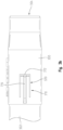
Fig. 3a is an elevated perspective view of one embodiment of a sliding connector; -
Fig. 3b is a top view of the sliding connector ofFig. 3a ; -
Fig. 4a is a section side view of the sliding connector ofFig. 3a coupled to a tube in an extended displacement; -
Fig 4b is a section side view of the sliding connector ofFig. 3a coupled to a tube in an retracted displacement; -
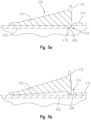
Fig. 5a is a detailed section view of a locking assembly of the sliding connector ofFig. 3a in a latched orientation; -
Fig. 5b is a detailed section view of the locking assembly of the sliding connector ofFig. 3a in a released orientation; -
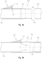
Fig. 6a is a section side view of the sliding connector ofFig. 3a coupled to the tube in the retracted displacement and spaced from a receiver; -
Fig. 6b is a section side view of the sliding connector ofFig. 3a coupled to the tube in the extended displacement and coupled to the receiver; -
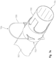
Fig. 7a is an elevated top perspective view of another embodiment of a sliding connector; -
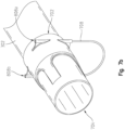
Fig. 7b is a lowered bottom perspective view of the sliding connector ofFig. 7a ; -
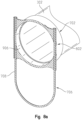
Fig. 8a is a section perspective view of the sliding connector ofFig. 7a with a wicket in a locked orientation; -
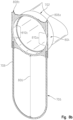
Fig. 8b is a section perspective view of the sliding connector ofFig. 7a with a wicket in a released orientation; -
Fig. 9a is a section side view of the sliding connector ofFig. 7a in an extended displacement and coupled to a receiver; -
Fig. 9b is a section side view of the sliding connector ofFig. 7a in a retracted displacement and spaced from the receiver; -
Fig. 10a is a section front view of the sliding connector ofFig. 7a with a wicket in a locked orientation; -
Fig. 10b is a section front view of the sliding connector ofFig. 7a with a wicket in a released orientation; -
Fig 11a is a schematic representation of two manifolds with no tube positioned there between; -
Fig. 11b is a schematic view of the two manifolds ofFig. 11a with a tube and sliding connector in a retracted displacement; and -
Fig. 11c is a schematic view of the two manifolds ofFig. 11b with the tube and sliding connector in an extended displacement. - The embodiments of the present disclosure described below are not exhaustive and do not limit the disclosure to the precise forms in the following detailed description. Rather, the embodiments are chosen and described so that others skilled in the art may appreciate and understand the principles and practices of the present disclosure.
-
Figs. 1-2 illustrate a conventional air seeder assembly.Fig. 1 is a partial, side schematic view of an agricultural vehicle, and more particularly anair cart 12.Air cart 12 is towed by a tilling implement 14 with a portion of a rear hitch 16 illustrated inFIG. 1 . The tilling implement 14 is an air drill but can be configured differently in other embodiments. In one embodiment, the tilling implement 14 includes a planter and theair cart 12 can be used to refill mini-hoppers on the planter.Air cart 12 can also include a rear hitch allowingair cart 12 to be towed in front of, rather than behind, tilling implement 14. -
Air cart 12 includes aframe 18 which in turn includesfront wheels 20,rear wheels 22,tank 24,blower 26, andauger 28. In the illustrated form, thetank 24 includes three separate mini-tanks or compartments 24A, 24B, and 24C with each mini-tank or compartment containing a material that is to be deposited or placed into the soil. Some materials include seed, fertilizer, insecticide, and herbicide among others. Each mini-tank orcompartment top lid 30 that can be opened to fill the mini-tanks 24A, 24B, and 24C with material and then closed. -
Air cart 12 includes apneumatic distribution system 32 for delivering the air-entrained materials to the soil where trenches or rows have been formed by the tilling implement 14.Pneumatic distribution system 32 includes ametering system 27,blower 26 and a plurality ofair lines 36. Themetering system 27 dispenses material from thetanks multiple conveyance tubes 50 and from there the product is conveyed to an air seeder via a plurality ofair lines 36. Although the illustrated embodiment includes threeair lines 36, it is contemplated that a corresponding amount ofair lines 36 asconveyance tubes 50 would be implemented. Theconveyance tubes 50 extend to and terminate at afluid line connection 60 for coupling with the manifold 52. - In one aspect of this disclosure,
air lines 36 may be primary air lines that selectively direct fluid from thetank 24 to the remaining portions of thepneumatic distribution system 38. Theprimary air lines 36 may typically be installed after thetank 24,metering system 27, andmanifold 52 are installed on theair cart 12. As such, theprimary air lines 36 must be able to be removeably coupled between two substantially fixed locations. Further, often a user needs to remove theprimary air line 36 to service theair cart 12 or fix a clog or other issue with theprimary air line 36. - Referring now to
Fig. 3 , one embodiment of a slidingconnector 300 is illustrated. The slidingconnector 300 may be sized to slide over apipe 302 on apipe receiving end 303 and have acoupling end 304 on the opposite end. Thecoupling end 304 may be sized to be selectively fluidly coupled to thetank 24,metering system 27,manifold 52 or any other part of thepneumatic distribution system 32. Regardless, the slidingconnector 300 is sized to slide along the pipe 302 a slidingdistance 306 between a latchedorientation 402 wherein the slidingconnector 300 is extended relative to adistal end 410 of thepipe 302 and a releasedorientation 404 wherein the slidingconnector 300 can be transitioned to a collapsed configuration wherein the slidingconnector 300 extends a retracteddisplacement 406 from thedistal end 410 of thepipe 302. In one aspect of this disclosure, the slidingconnector 300 may haveindicia 322 thereon the provides an indication of the proper orientation of the slidingconnector 300 with reference to the air flow direction of thepneumatic distribution system 32. - In the released
orientation 404, the slidingconnector 300 can be oriented the retracteddisplacement 406 from adistal end 410 of thecorresponding pipe 302. Alternatively, in the latchedorientation 402, alatch 308 may engage thedistal end 410 of thepipe 302 to selectively prevent the slidingconnector 300 from sliding towards thedistal end 410, thereby establishing anextended displacement 408 of the slidingconnector 300 relative to thedistal end 410 of thepipe 302. Theextended displacement 408 may be sufficiently greater than the retracteddisplacement 406 so that thecoupling end 304 of the slidingconnector 300 can be selectively coupled to a receiver (such as thetank 24,metering system 27, or manifold 52) as the sliding connector transitions from the releasedorientation 404 to the latchedorientation 402. - The sliding
connector 300 may have alocking mechanism 310 that utilizes thelatch 308 to selectively maintain the slidingconnector 300 in the latchedorientation 402. More specifically, thelatch 308 may be naturally biased at least partially radially inward of aninner connector wall 412 of abody 414 of the slidingconnector 300. With this configuration, when the slidingconnector 300 is moved theextended displacement 408 from thedistal end 410, thelocking mechanism 310 may engaged thedistal end 310 as thelatch 308 naturally biases radially inward to the latchedorientation 402 as thelatch 308 is no longer positioned along the radially outer surface of thepipe 302. Once thelatch 308 is orientated in the latchedorientation 402, thelatch 308 may contact thedistal end 410 of thepipe 302 when a force is applied to the slidingconnector 300 towards thepipe 302. The contact between thelatch 308 and thedistal end 410 of thepipe 302 may be sufficient to substantially maintain the slidingconnector 300 in theextended displacement 408 even when forces act on the slidingconnector 300 towards thepipe 302. - The
locking mechanism 310 may be elastically deformable to selectively transition thelatch 308 to the releasedorientation 404 wherein thelatch 308 does not substantially contact thedistal end 410 of thepipe 302. More specifically, thelocking mechanism 310 may have a pushingsurface 312 wherein a user may apply a push force PF to thelocking mechanism 310 to transition thelatch 308 from the latchedorientation 402 to the releasedorientation 404. The push force PF may be such that an average adult can apply the push force PF with only a finger or thumb. In other words, the push force PF can be applied by a user without the use of additional tools. More specifically, the user may use a finger or similar object to press the pushingsurface 412 to draw thelatch 308 radially away from thetube 302. Once thelatch 308 is sufficiently spaced from thedistal end 410 of thetube 302, the slidingconnector 300 can transition from the latchedorientation 402 to the releasedorientation 404. - In one aspect of this disclosure, the
latch 308 may have an angled profile. In this configuration, thelatch 308 may easily slide along the slidingdistance 306 towards theextended displacement 408. However, thelatch 308 may inhibit movement towards the retracteddisplacement 406 unless the pushingsurface 312 is engaged to bias thelatch 308 away from the radially external surface of thepipe 302. - In another aspect of this disclosure, the
locking mechanism 310 may be formed from acutout 314 through a portion of the slidingconnector 300. In one aspect of this disclosure, thecutout 314 may be substantially U-shaped. However, other shapes are considered herein. This configuration may allow thelatch 308 to be selectively deflected away from thepipe 302 while staying connected to the slidingconnector 300. Further still, this configuration allows thelocking mechanism 310 to be formed from the same material as the remaining components of the slidingconnector 300. - The
locking mechanism 310 may also have astiffening support 316. Thestiffening support 316 may run from the pushingsurface 412 towards thepipe receiving end 303 at least partially between portions of thecutout 314. Thestiffening support 316 may provide a reinforcement to thelatch 308 to alter the pushing force PF required on the pushingsurface 312 to transition thelatch 308 to the released orientation. In one example, the width of thestiffening support 316 may be selected to provide the desired stiffening effect on thelatch 308. More specifically, awider stiffening support 316 may require a greater pushing force PF on the pushingsurface 312 to transition thelatch 308 to the released orientation compared to a relativelythinner stiffening support 316. - In one aspect of this disclosure, the
cutout 314 may have a gap that can be filled or otherwise covered with adeflectable seal 320. More specifically, the gap in the slidingconnector 300 created by thecutout 314 may be filled with thedeflectable seal 320 which may be a material that prevents fluid from transition from a radially inner portion of the slidingconnector 300 to a radially outer portion of theinner connector 300 through the gap. This may prevent any commodity or air flow from exiting thepneumatic system 27 through thecutout 314. Further, thedeflectable seal 320 may be in or over thecutout 314 and may be malleable such that thelocking mechanism 310 can still transition thelatch 308 between the latchedorientation 402 to the releasedorientation 404 without tearing or otherwise compromising the material in or over thecutout 314. In this configuration, the material in or over thegap 320 of thecutout 314 allows thelocking mechanism 310 to function as described herein while maintaining a fluid seal along thecutout 314. - In use and with reference to
Figs. 6a and 6b , the slidingconnector 300 may be in the retracteddisplacement 406 and thecoupling end 304 aligned with areceiver 602 inconfiguration 600. In thisconfiguration 600, the lockingassembly 310 is in the releasedorientation 404 and the slidingconnector 300 can slide relative to thepipe 302 axially alongaxis 604. More specifically, the slidingconnector 300 may be slid axially relative to thepipe 302 to theextended displacement 408 as illustrated in anextended configuration 601 ofFig. 6b . In theextended configuration 601, thecoupling end 304 is fluidly coupled to thereceiver 602 as thelatch 308 engages thedistal end 410 of thepipe 302 to selectively hold the slidingconnector 300 in theextended configuration 601. Thelatch 308 engages any portion of thedistal end 410 of thepipe 302 such that the slidingconnector 300 can be any angular orientation about theaxis 604 and still be locked in the extended configuration by thelatch 308. That is to say, the slidingconnector 300 can be rotated about theaxis 604 and thelatch 308 will still properly engage thedistal end 410 of thepipe 302. In one aspect this feature may allow the user to position thelocking mechanism 310 at an easily accessible location because the slidingconnector 300 can be rotated relative to thetube 302 without affect the functionality discussed herein. - In the
extended configuration 601, fluid within thetube 302 is directed through the slidingconnector 300 and to thereceiver 602 without substantially escaping through the slidingconnector 300. In the embodiment ofFigs. 6a and 6b , thecoupling end 304 is sized to fit radially within thereceiver 602. However, other embodiments contemplated herein have acoupling end 304 sized to fit radially around thereceiver 602. Further still, thereceiver 602 may be a bracket coupled to a meter assembly, a manifold, or any other part of thepneumatic system 27. - To remove the sliding
connector 300 from thereceiver 602, a user may press on the pushingsurface 312 of thelocking mechanism 310 to transition thelatch 308 to the releasedorientation 404. Then, the slidingconnector 300 can be slide away from thereceiver 602 until the sliding connector is in the retracteddisplacement 406 wherein thecoupling end 304 is at least partially spaced from thereceiver 602. In the retracteddisplacement 406, the slidingconnector 300 andpipe 302 may be removed from thepneumatic system 27 and serviced as needed. As mentioned herein, the entire process of coupling, or removing, the slidingconnector 300 to thereceiver 602 can be done by applying the push force PF to the pushingsurface 312, which can be done by a user without the use of additional tools. - Referring now to
Figs. 7a-10b another embodiment of a slidingconnector 700 is illustrated. The slidingconnector 700 may provide similar advantages as the slidingconnector 300 in that the slidingconnector 700 has apipe receiving end 702 sized to slidably fit over apipe 302 such as a conveyance tube or the like. The slidingconnector 700 is selectably transitionable between a lockedorientation 802 and a releasedorientation 804. Also similar to the slidingconnector 300, the slidingconnector 700 can be positioned by a user in either the locked orientation or the released orientation without the use of tools. - In the released
orientation 804, alocking mechanism 706 may have awicket 708 with two ends positioned in parallel throughholes wicket 708 being in a spacedconfiguration 806 from the slidingconnector 700. In the spacedconfiguration 806, thewicket 708 may be partially positioned within the throughholes wicket 708 is not be occupyingtangential pathways connector 700 defined in part by the throughholes tangential pathways inner wall 906 of the slidingconnector 700. In the spacedconfiguration 806, thewicket 708 does not occupy thetangential pathways pipe 302 may slide passed the throughholes wicket 708 so the slidingconnector 700 slide to a retracteddisplacement 902 wherein thecoupling end 704 is spaced a minimal distance from thedistal end 410 of thepipe 302. - However, the sliding
connector 700 may be slidable along thepipe 302 to be positioned in anextended displacement 904 wherein the slidingconnector 700 is extended farther from the distal end of thetube 302 compared to the retracteddisplacement 902. The slidingconnector 700 may slide sufficiently far along thetube 302 such that no portion of thetube 302 is positioned to block thewicket 708 from being positioned through thetangential pathways holes orientation 802. In other words, once the slidingconnector 700 is extended sufficiently far from thedistal end 410 of thetube 302 thewicket 708 may be fully positioned through the throughholes wicket 708 may be pressed into the lockedorientation 802. In the lockedorientation 802, thewicket 708 passes through thetangential pathways holes connector 700. - In the locked
orientation 802, thewicket 708 is positioned within the throughholes wicket 708 extends at least partially radially inward from the radiallyinner wall 906 of the slidingconnector 700. In this configuration, the slidingconnector 700 cannot slide along thetube 302 to the retracteddisplacement 902 because thewicket 708 will contact thedistal end 410 of thetube 302, preventing the slidingconnector 700 from sliding further to the retracteddisplacement 902. However, once thewicket 708 is transitioned to the spacedconfiguration 806, thewicket 708 no longer occupies the portion of thetangential pathways holes wicket 708 to interfere with and contact thedistal end 410 of thetube 302. - In one aspect of this disclosure, the
wicket 708 may be transitioned by a user between the lockedorientation 802 and the releasedorientation 804 by pulling or pushing thewicket 708 radially towards or away from the slidingconnector 700. In other words, thewicket 708 may be slidable by a user without the use of additional tools as long as the slidingconnector 700 is in theextended displacement 904. - In use, the sliding
connector 700 may be in theextended displacement 904 as illustrated inFig. 9a . Thewicket 708 may be in the lockedorientation 802 such that portions of thewicket 708 extend radially inward from theinner wall 906 of the slidingconnector 700 along thetangential pathways distal end 410 of thetube 302 if the slidingconnector 700 is forced towards the retracteddisplacement 902. Accordingly, in the lockedorientation 802, thewicket 708 substantially prevents the slidingconnector 700 from sliding towards the retracteddisplacement 902 and thereby maintains fluid coupling to thereceiver 602. - If a user wants to remove the sliding
connector 700 andtube 302 from thereceiver 602, the user may transition thewicket 708 to the spacedconfiguration 806 wherein thewicket 708 no longer occupies thetangential pathways holes wicket 708 in the spacedconfiguration 806, the slidingconnector 700 may slide towards the retracteddisplacement 902 because thedistal end 410 of thetube 302 does not contact thewicket 708 at thetangential pathways holes connector 700 andcorresponding tube 302 from thereceiver 602 by transitioning thewicket 708 to the spacedconfiguration 806 and sliding the sliding connector to the retracteddisplacement 902. In the retracted position, thecoupling end 704 may be free of thereceiver 602 such that the slidingcoupler 700 andcorresponding tube 302 may be removed therefrom. - Similar to the sliding
connector 300, the slidingconnector 700 may be effectively locked in theextended displacement 904 with thelocking mechanism 706 regardless of the rotation of the slidingconnector 700 about theaxis 604. More specifically, when thewicket 708 is in the lockedorientation 802 thewicket 708 will contact thedistal end 410 of thetube 302 regardless of the rotation of the slidingconnector 700 about theaxis 904 relative to thetube 302. In this configuration, the user can rotate the slidingconnector 700 so thewicket 708 is easily accessible to the user to selectively transition the wicket to the releasedorientation 804 as needed. - Referring now to
Figs. 11a-11c , one embodiment of an installation sequence utilizing a slidingconnector Fig. 11a illustrates a first andsecond manifold first manifold 52a may have anupstream receiver 1102 and thesecond manifold 52b may have thereceiver 602 discussed herein. Theupstream receiver 1102 may be sized to fit radially within thetube 302. Alternatively, theupstream receiver 1102 may have a coupler sized to fit radially around the outer surface of thetube 302. Regardless, inFig. 11b theconnector 300 may be in the retracteddisplacement 406 wherein anopen end 1104 of thetube 302 may be coupled to theupstream receiver 1102. More specifically, the retracteddisplacement 406 of the slidingconnector 300 provides sufficient clearance between theupstream receiver 1102 andreceiver 602 so thetube 302 and slidingconnector 300 fit there between to couple theopen end 1104 of thetube 302 to theupstream receiver 1102. As mentioned herein, theopen end 1104 may be coupled around, or within, theupstream receiver 1102. - With the
open end 1104 coupled to theupstream receiver 1102 and the slidingconnector 300 in the retracteddisplacement 406, there may begap 1106 between thecoupling end 304 of the slidingconnector 300 and thereceiver 602. Thegap 1106 allows the slidingconnector 300 andtube 302 to be aligned with thereceiver 602. Once aligned with thereceiver 602, the slidingconnector 300 may slide to theextended displacement 408 as thecoupling end 304 slides into thereceiver 602 until thelocking mechanism 310 transitions to the latchedorientation 402. Once the slidingconnector 300 is in theextended displacement 408 and thelocking mechanism 310 is in the latchedorientation 402 as illustrated inFig. 11c , thetube 302 and slidingconnector 300 are substantially locked between themanifolds upstream receiver 1102, through thetube 302 and slidingconnector 300, and into thereceiver 602. - The
tube 302 and slidingconnector 300 can be removed from themanifolds assembly 310 to the releasedorientation 404 as discussed herein and sliding the slidingconnector 300 to the retracteddisplacement 406. Thegap 1106 allows thetube 302 and slidingconnector 300 to be moved away from both thereceiver 602 andupstream receiver 1102 to fully remove thetube 302 and slidingconnector 300 from themanifolds - While
manifolds Figs. 11a-11c , any fluid coupling locations on anair cart 12 or other agricultural machine are considered herein and themanifolds Figs. 11a-11c depict the slidingconnector 300, it is also contemplated herein to use slidingconnector 700 instead of slidingconnector 300. The slidingconnector 700 can transition between the retracteddisplacement 902 and theextended displacement 904 as discussed herein and can therefore be implemented in substantially the same way as the slidingconnector 300.
Claims (15)
- A sliding connector pipe assembly, comprising:a pipe (302) defining an axis (604) and configured to direct fluid flow;a sliding connector (300) slidably positioned around an end portion of the pipe (302), the sliding connector (300) being selectively slidable between an extended displacement and a retracted displacement relative to the pipe (302); anda locking mechanism (310) that selectively prevents axial movement of the sliding connector (300) from the extended displacement to the retracted displacement;wherein the locking mechanism (310) prevents the sliding member from transition from the extended displacement to the retracted displacement regardless of the rotational orientation of the sliding connector (300) relative to the pipe (302) about the axis (604).
- The assembly of claim 1, wherein the locking mechanism (310) is selectively releasable to allow the sliding connector (300) to transition from the extended displacement to the retracted displacement.
- The assembly of claim 1 or 2, wherein the locking mechanism (310) is selectively releasable without the use of additional tools.
- The assembly of one of the claims 1 to 3, wherein the sliding connector (300) has a coupling end (304) sized to fit within a receiver (602) to fluidly couple the pipe (302) to the receiver (602) when the sliding connector (300) is in the extended displacement.
- The assembly of claim 4, wherein the sliding connector (300) has a sliding distance between the retracted displacement and the extended displacement, wherein the sliding distance is sufficient to allow the coupling end (304) to at least partially overlap the receiver (602) when in the extended displacement.
- The assembly of one of the claims 1 to 5, wherein the locking mechanism (310) comprises a latch (308) that extends at least partially radially inwardly past an inner connector wall (412) in a latched orientation.
- The assembly of claim 6, wherein the latch (308) is positioned at least partially radially inwardly past the inner connector wall (412) in a neutral state.
- The assembly or claim 6 or 7, wherein the latch (308) is deflectable to a released orientation wherein the latch (308) does not substantially extend radially inwardly past the inner connector wall (412).
- The assembly of one of the claims 1 to 8, wherein the locking mechanism (310) is formed of the same material as a body (414) of the sliding connector (300).
- The assembly of one of the claims 6 to 9, wherein the latch (308) is formed, in part, of a cutout (314) of the sliding connector (300).
- The assembly of claim 10, wherein the cutout (314) has a deflectable seal (320) therein to prevent fluid from passing through the U-shaped cutout (314).
- The assembly of one of the claims 6 to 11, further wherein the latch (308) comprises a stiffening support (316) to alter a push force required to deflect the latch (308) to the released orientation.
- The assembly of one of the claims 1 to 5, wherein the locking mechanism (310) comprises a wicket (708) slidable through corresponding through holes (808a, 808b) of the sliding connector (300) between a locked orientation and a released orientation, wherein in the locked orientation at least a portion of the wicket (708) extends radially inward from an inner connector wall (412) to prevent the pipe (302) from sliding thereby and in the released orientation the wicket (708) does not extend past the inner connector wall (412) and the pipe (302) can slide thereby.
- The assembly of claim 13, wherein in the locked orientation the wicket (708) extends radially inward from the inner connector wall (412) at two separate locations.
- The assembly of one of the claims 4 to 14, wherein the locking mechanism (310) selectively locks the sliding connector (300) in the extended displacement partially overlapping the receiver (602).
Applications Claiming Priority (1)
| Application Number | Priority Date | Filing Date | Title |
|---|---|---|---|
| US18/093,117 US12578046B2 (en) | 2023-01-04 | 2023-01-04 | Air conveyance quick connect fitting |
Publications (2)
| Publication Number | Publication Date |
|---|---|
| EP4397897A1 true EP4397897A1 (en) | 2024-07-10 |
| EP4397897B1 EP4397897B1 (en) | 2025-09-24 |
Family
ID=89168302
Family Applications (1)
| Application Number | Title | Priority Date | Filing Date |
|---|---|---|---|
| EP23215561.4A Active EP4397897B1 (en) | 2023-01-04 | 2023-12-11 | Sliding connector pipe assembly |
Country Status (4)
| Country | Link |
|---|---|
| US (1) | US12578046B2 (en) |
| EP (1) | EP4397897B1 (en) |
| AU (1) | AU2023274163A1 (en) |
| CA (1) | CA3221505A1 (en) |
Citations (4)
| Publication number | Priority date | Publication date | Assignee | Title |
|---|---|---|---|---|
| EP1104865A1 (en) * | 1999-12-01 | 2001-06-06 | Legrand S.p.A. | A connector for corrugated conduits |
| EP1375993A1 (en) * | 2002-06-24 | 2004-01-02 | Zehnder Verkaufs- und Verwaltungs AG | Coupling sleeve for corrugated pipes |
| DE102008013157A1 (en) * | 2008-03-07 | 2009-09-10 | Bayerische Motoren Werke Aktiengesellschaft | Hose connector for fixing hose on connecting piece, has securing shanks that are axially deformed, where ends of shanks are radially and inwardly deformed, and deformed sections of shanks lie on outer side of hose at obstructed condition |
| CN107504297A (en) * | 2017-02-24 | 2017-12-22 | 黄浩 | Thin-wall stainless steel pipe fitting interconnects tube head with tubing |
Family Cites Families (14)
| Publication number | Priority date | Publication date | Assignee | Title |
|---|---|---|---|---|
| US2793055A (en) * | 1952-08-02 | 1957-05-21 | Lewyt Corp | Telescopic coupling with cam latch means |
| CH655561B (en) * | 1982-02-05 | 1986-04-30 | ||
| US4625998A (en) * | 1984-04-02 | 1986-12-02 | Draudt Donald A | Swivel hose couplings |
| US4836580A (en) * | 1988-03-01 | 1989-06-06 | Scepter Manufacturing Company Limited | Conduit connector |
| JP2514706B2 (en) * | 1988-12-29 | 1996-07-10 | 株式会社日立製作所 | Electric vacuum cleaner |
| AUPP124098A0 (en) * | 1998-01-07 | 1998-01-29 | Tubalco Manufacturing Pty Ltd | Locking arrangement for telescopically moving tubes |
| SE518739C2 (en) * | 1998-03-12 | 2002-11-12 | Electrolux Ab | Pipe shaft for a vacuum cleaner |
| DE10059052A1 (en) * | 2000-11-28 | 2002-06-06 | Froh House Tech Gmbh & Co Kg | Telescopic vacuum cleaner suction pipe |
| US6612533B2 (en) | 2001-07-09 | 2003-09-02 | Cabinet-Eaz L.L.C. | Adjustable support |
| US6791031B1 (en) * | 2003-06-05 | 2004-09-14 | James C. Manning | Electrical conduit fitting and method |
| WO2014042294A1 (en) | 2012-09-13 | 2014-03-20 | 은성전자 주식회사 | Length adjustment device for extension pipe for telescope |
| US9374944B2 (en) * | 2013-01-25 | 2016-06-28 | Cnh Industrial Canada, Ltd. | Fluid line connection for an agricultural air seeder |
| US9604320B1 (en) | 2015-11-24 | 2017-03-28 | Neyda Yadira Fuentes | Counterbalance pipe |
| TWI700438B (en) | 2018-10-18 | 2020-08-01 | 錦聖科技股份有限公司 | Positioning fasteners for telescopic support rods |
-
2023
- 2023-01-04 US US18/093,117 patent/US12578046B2/en active Active
- 2023-11-29 CA CA3221505A patent/CA3221505A1/en active Pending
- 2023-11-30 AU AU2023274163A patent/AU2023274163A1/en active Pending
- 2023-12-11 EP EP23215561.4A patent/EP4397897B1/en active Active
Patent Citations (4)
| Publication number | Priority date | Publication date | Assignee | Title |
|---|---|---|---|---|
| EP1104865A1 (en) * | 1999-12-01 | 2001-06-06 | Legrand S.p.A. | A connector for corrugated conduits |
| EP1375993A1 (en) * | 2002-06-24 | 2004-01-02 | Zehnder Verkaufs- und Verwaltungs AG | Coupling sleeve for corrugated pipes |
| DE102008013157A1 (en) * | 2008-03-07 | 2009-09-10 | Bayerische Motoren Werke Aktiengesellschaft | Hose connector for fixing hose on connecting piece, has securing shanks that are axially deformed, where ends of shanks are radially and inwardly deformed, and deformed sections of shanks lie on outer side of hose at obstructed condition |
| CN107504297A (en) * | 2017-02-24 | 2017-12-22 | 黄浩 | Thin-wall stainless steel pipe fitting interconnects tube head with tubing |
Also Published As
| Publication number | Publication date |
|---|---|
| EP4397897B1 (en) | 2025-09-24 |
| CA3221505A1 (en) | 2024-07-04 |
| US12578046B2 (en) | 2026-03-17 |
| US20240218949A1 (en) | 2024-07-04 |
| AU2023274163A1 (en) | 2024-07-18 |
Similar Documents
| Publication | Publication Date | Title |
|---|---|---|
| CA2151020E (en) | Multi compartment air seeder | |
| AU2010202169B2 (en) | Volumetric metering system with sectional shut-off | |
| CA2721975C (en) | Pneumatic seed distribution hose coupling assembly | |
| CA1323054C (en) | Pneumatic manifold quick coupling | |
| US10660263B2 (en) | Method for securing an inductor segment to an inductor assembly of an agricultural implement | |
| US9148991B2 (en) | Gate retention for an inductor box of an agricultural implement | |
| US20200221631A1 (en) | Flow splitter for distributing agricultural products and related system | |
| US9913423B2 (en) | Fluid line connection for an agricultural air seeder | |
| US20170299098A1 (en) | Quick coupling for flexible tube | |
| US12578046B2 (en) | Air conveyance quick connect fitting | |
| US12069982B2 (en) | Metering unit for granular material | |
| US10117376B2 (en) | Equalizing air pressure on air seeders | |
| US6622646B1 (en) | Mounting assembly for hydraulic coupling | |
| US12356883B2 (en) | Quick disconnect conveyance tubes | |
| US9826675B2 (en) | Gauge wheel assembly with hinge | |
| BR102020009044B1 (en) | FLUID LINE CONNECTION |
Legal Events
| Date | Code | Title | Description |
|---|---|---|---|
| PUAI | Public reference made under article 153(3) epc to a published international application that has entered the european phase |
Free format text: ORIGINAL CODE: 0009012 |
|
| STAA | Information on the status of an ep patent application or granted ep patent |
Free format text: STATUS: THE APPLICATION HAS BEEN PUBLISHED |
|
| AK | Designated contracting states |
Kind code of ref document: A1 Designated state(s): AL AT BE BG CH CY CZ DE DK EE ES FI FR GB GR HR HU IE IS IT LI LT LU LV MC ME MK MT NL NO PL PT RO RS SE SI SK SM TR |
|
| STAA | Information on the status of an ep patent application or granted ep patent |
Free format text: STATUS: REQUEST FOR EXAMINATION WAS MADE |
|
| 17P | Request for examination filed |
Effective date: 20250110 |
|
| GRAP | Despatch of communication of intention to grant a patent |
Free format text: ORIGINAL CODE: EPIDOSNIGR1 |
|
| STAA | Information on the status of an ep patent application or granted ep patent |
Free format text: STATUS: GRANT OF PATENT IS INTENDED |
|
| RIC1 | Information provided on ipc code assigned before grant |
Ipc: A01C 7/04 20060101ALI20250508BHEP Ipc: F16L 25/10 20060101AFI20250508BHEP Ipc: F16L 37/14 20060101ALI20250508BHEP Ipc: F16L 27/12 20060101ALI20250508BHEP |
|
| INTG | Intention to grant announced |
Effective date: 20250522 |
|
| GRAS | Grant fee paid |
Free format text: ORIGINAL CODE: EPIDOSNIGR3 |
|
| GRAA | (expected) grant |
Free format text: ORIGINAL CODE: 0009210 |
|
| STAA | Information on the status of an ep patent application or granted ep patent |
Free format text: STATUS: THE PATENT HAS BEEN GRANTED |
|
| AK | Designated contracting states |
Kind code of ref document: B1 Designated state(s): AL AT BE BG CH CY CZ DE DK EE ES FI FR GB GR HR HU IE IS IT LI LT LU LV MC ME MK MT NL NO PL PT RO RS SE SI SK SM TR |
|
| REG | Reference to a national code |
Ref country code: GB Ref legal event code: FG4D |
|
| REG | Reference to a national code |
Ref country code: CH Ref legal event code: EP |
|
| REG | Reference to a national code |
Ref country code: DE Ref legal event code: R096 Ref document number: 602023006940 Country of ref document: DE |
|
| REG | Reference to a national code |
Ref country code: IE Ref legal event code: FG4D |
|
| PGFP | Annual fee paid to national office [announced via postgrant information from national office to epo] |
Ref country code: DE Payment date: 20251119 Year of fee payment: 3 |
|
| PG25 | Lapsed in a contracting state [announced via postgrant information from national office to epo] |
Ref country code: NO Free format text: LAPSE BECAUSE OF FAILURE TO SUBMIT A TRANSLATION OF THE DESCRIPTION OR TO PAY THE FEE WITHIN THE PRESCRIBED TIME-LIMIT Effective date: 20251224 |
|
| REG | Reference to a national code |
Ref country code: LT Ref legal event code: MG9D |
|
| PGFP | Annual fee paid to national office [announced via postgrant information from national office to epo] |
Ref country code: AT Payment date: 20260113 Year of fee payment: 3 |
|
| PG25 | Lapsed in a contracting state [announced via postgrant information from national office to epo] |
Ref country code: FI Free format text: LAPSE BECAUSE OF FAILURE TO SUBMIT A TRANSLATION OF THE DESCRIPTION OR TO PAY THE FEE WITHIN THE PRESCRIBED TIME-LIMIT Effective date: 20250924 |
|
| PG25 | Lapsed in a contracting state [announced via postgrant information from national office to epo] |
Ref country code: HR Free format text: LAPSE BECAUSE OF FAILURE TO SUBMIT A TRANSLATION OF THE DESCRIPTION OR TO PAY THE FEE WITHIN THE PRESCRIBED TIME-LIMIT Effective date: 20250924 |
|
| PGFP | Annual fee paid to national office [announced via postgrant information from national office to epo] |
Ref country code: FR Payment date: 20251226 Year of fee payment: 3 |
|
| PG25 | Lapsed in a contracting state [announced via postgrant information from national office to epo] |
Ref country code: GR Free format text: LAPSE BECAUSE OF FAILURE TO SUBMIT A TRANSLATION OF THE DESCRIPTION OR TO PAY THE FEE WITHIN THE PRESCRIBED TIME-LIMIT Effective date: 20251225 |
|
| PG25 | Lapsed in a contracting state [announced via postgrant information from national office to epo] |
Ref country code: SE Free format text: LAPSE BECAUSE OF FAILURE TO SUBMIT A TRANSLATION OF THE DESCRIPTION OR TO PAY THE FEE WITHIN THE PRESCRIBED TIME-LIMIT Effective date: 20250924 |
|
| PG25 | Lapsed in a contracting state [announced via postgrant information from national office to epo] |
Ref country code: LV Free format text: LAPSE BECAUSE OF FAILURE TO SUBMIT A TRANSLATION OF THE DESCRIPTION OR TO PAY THE FEE WITHIN THE PRESCRIBED TIME-LIMIT Effective date: 20250924 |
|
| PG25 | Lapsed in a contracting state [announced via postgrant information from national office to epo] |
Ref country code: BG Free format text: LAPSE BECAUSE OF FAILURE TO SUBMIT A TRANSLATION OF THE DESCRIPTION OR TO PAY THE FEE WITHIN THE PRESCRIBED TIME-LIMIT Effective date: 20250924 |
|
| PG25 | Lapsed in a contracting state [announced via postgrant information from national office to epo] |
Ref country code: RS Free format text: LAPSE BECAUSE OF FAILURE TO SUBMIT A TRANSLATION OF THE DESCRIPTION OR TO PAY THE FEE WITHIN THE PRESCRIBED TIME-LIMIT Effective date: 20251224 |
|
| REG | Reference to a national code |
Ref country code: NL Ref legal event code: MP Effective date: 20250924 |
|
| PG25 | Lapsed in a contracting state [announced via postgrant information from national office to epo] |
Ref country code: NL Free format text: LAPSE BECAUSE OF FAILURE TO SUBMIT A TRANSLATION OF THE DESCRIPTION OR TO PAY THE FEE WITHIN THE PRESCRIBED TIME-LIMIT Effective date: 20250924 |
|
| REG | Reference to a national code |
Ref country code: AT Ref legal event code: MK05 Ref document number: 1840555 Country of ref document: AT Kind code of ref document: T Effective date: 20250924 |
|
| PG25 | Lapsed in a contracting state [announced via postgrant information from national office to epo] |
Ref country code: SM Free format text: LAPSE BECAUSE OF FAILURE TO SUBMIT A TRANSLATION OF THE DESCRIPTION OR TO PAY THE FEE WITHIN THE PRESCRIBED TIME-LIMIT Effective date: 20250924 |
|
| PG25 | Lapsed in a contracting state [announced via postgrant information from national office to epo] |
Ref country code: ES Free format text: LAPSE BECAUSE OF FAILURE TO SUBMIT A TRANSLATION OF THE DESCRIPTION OR TO PAY THE FEE WITHIN THE PRESCRIBED TIME-LIMIT Effective date: 20250924 |
|
| PG25 | Lapsed in a contracting state [announced via postgrant information from national office to epo] |
Ref country code: AT Free format text: LAPSE BECAUSE OF FAILURE TO SUBMIT A TRANSLATION OF THE DESCRIPTION OR TO PAY THE FEE WITHIN THE PRESCRIBED TIME-LIMIT Effective date: 20250924 |
|
| PG25 | Lapsed in a contracting state [announced via postgrant information from national office to epo] |
Ref country code: RO Free format text: LAPSE BECAUSE OF FAILURE TO SUBMIT A TRANSLATION OF THE DESCRIPTION OR TO PAY THE FEE WITHIN THE PRESCRIBED TIME-LIMIT Effective date: 20250924 Ref country code: IT Free format text: LAPSE BECAUSE OF FAILURE TO SUBMIT A TRANSLATION OF THE DESCRIPTION OR TO PAY THE FEE WITHIN THE PRESCRIBED TIME-LIMIT Effective date: 20250924 |
|
| PG25 | Lapsed in a contracting state [announced via postgrant information from national office to epo] |
Ref country code: IS Free format text: LAPSE BECAUSE OF FAILURE TO SUBMIT A TRANSLATION OF THE DESCRIPTION OR TO PAY THE FEE WITHIN THE PRESCRIBED TIME-LIMIT Effective date: 20260124 |
|
| PG25 | Lapsed in a contracting state [announced via postgrant information from national office to epo] |
Ref country code: PT Free format text: LAPSE BECAUSE OF FAILURE TO SUBMIT A TRANSLATION OF THE DESCRIPTION OR TO PAY THE FEE WITHIN THE PRESCRIBED TIME-LIMIT Effective date: 20260126 Ref country code: CZ Free format text: LAPSE BECAUSE OF FAILURE TO SUBMIT A TRANSLATION OF THE DESCRIPTION OR TO PAY THE FEE WITHIN THE PRESCRIBED TIME-LIMIT Effective date: 20250924 |
|
| PG25 | Lapsed in a contracting state [announced via postgrant information from national office to epo] |
Ref country code: PL Free format text: LAPSE BECAUSE OF FAILURE TO SUBMIT A TRANSLATION OF THE DESCRIPTION OR TO PAY THE FEE WITHIN THE PRESCRIBED TIME-LIMIT Effective date: 20250924 |
|
| PG25 | Lapsed in a contracting state [announced via postgrant information from national office to epo] |
Ref country code: EE Free format text: LAPSE BECAUSE OF FAILURE TO SUBMIT A TRANSLATION OF THE DESCRIPTION OR TO PAY THE FEE WITHIN THE PRESCRIBED TIME-LIMIT Effective date: 20250924 Ref country code: SK Free format text: LAPSE BECAUSE OF FAILURE TO SUBMIT A TRANSLATION OF THE DESCRIPTION OR TO PAY THE FEE WITHIN THE PRESCRIBED TIME-LIMIT Effective date: 20250924 |